


Abstract
This study numerically investigates buoyancy-driven melting of a Williamson non-Newtonian phase change material in a porous enclosure. The model incorporates an inclined magnetic field, thermal radiation, and viscous dissipation. The enthalpy–porosity method is employed to describe the melting process. The governing equations are solved using an implicit finite-difference scheme and successive over-relaxation. Grid and time-step refinement are performed to assess numerical sensitivity, while comparisons with limiting-case benchmarks are used to validate selected components of the numerical implementation. The effects of the governing parameters on fluid flow, heat transfer, and melting behavior are examined. Higher Grashof and Darcy numbers strengthen circulation and accelerate melting. In contrast, larger Williamson and magnetic parameters, together with greater mushy-zone resistance, suppress fluid motion and delay melting. Thermal radiation and viscous dissipation enhance heating and promote melting. Higher Stefan numbers also accelerate melting and increase the liquid fraction. Overall, the results demonstrate that buoyancy, permeability, thermal radiation, viscous heating, and Stefan number promote PCM melting, whereas magnetic damping, non-Newtonian effects, and mushy-zone resistance inhibit it, providing insight into the competing transport mechanisms governing PCM melting in porous enclosures.
1. Introduction
Phase change materials (PCMs) have attracted considerable attention as latent heat storage media because they can absorb and release large amounts of thermal energy within a narrow temperature range, making them attractive for thermal energy storage (TES) applications [1]. Integrating them into building envelopes has shown significant potential to improve indoor thermal regulation and reduce energy consumption [2], while coupling PCM systems with radiative cooling technologies can further enhance passive cooling performance and building energy efficiency [3]. Despite these advantages, the widespread application of PCMs remains limited by their inherently low thermal conductivity, which results in slow melting and solidification processes and consequently restricts charging and discharging rates [4].
To overcome the low thermal conductivity of PCMs, heat transfer enhancement strategies generally follow two complementary routes: material-level modification and structure- and medium-level regulation. The first includes incorporating nanoparticles [5] and constructing interconnected, highly conductive filler networks within the PCM. Solid–solid phase change composites containing aligned graphite networks for solar/electro-thermal energy storage demonstrate how directional conductive pathways can improve thermal transport [6]. Since their rheological properties strongly influence the melting behavior of these materials, particular attention has been devoted to pseudoplastic and viscoplastic fluids [7]. In permeable systems, non-Newtonian effects significantly influence fluid circulation and heat transfer [8], while magnetic fields, porous resistance, and internal heat generation further modify the transport characteristics of electrically conducting fluids [9]. These studies demonstrate that several physical mechanisms affect the thermal performance of PCM systems; however, their combined influence on latent heat thermal energy storage remains only partially understood [10].
Among non-Newtonian constitutive models, the Williamson model has received considerable attention because it accurately represents shear-thinning fluids encountered in numerous engineering applications [11,12]. Researchers have investigated the rheological behavior of Williamson fluids in porous and fractured media [13], as well as in heat transfer problems involving permeable surfaces [14]. Additional studies have demonstrated that magnetic fields can significantly alter the momentum and thermal transport characteristics of electrically conducting non-Newtonian fluids [15], while thermal radiation and Ohmic dissipation further influence velocity and temperature distributions [16]. Variable thermal conductivity [17], slip effects and nanoparticle transport [18], porous-medium resistance and internal heat generation [19], and recent artificial intelligence approaches for predicting radiative heat transfer [20] have all contributed to improving the understanding of Williamson-fluid transport. Nevertheless, these investigations have generally considered convective flow configurations rather than phase-change processes, and they have devoted only limited attention to the melting behavior of Williamson-type phase change materials.
The enhancement of heat transfer during PCM melting has also been extensively investigated from the perspective of thermal energy storage applications [21]. Thermal radiation can contribute significantly to heat transfer, particularly in high-temperature thermal systems [22], and its combination with PCM-based walls has been shown to improve overall thermal performance [23]. Numerical simulation of melting and solidification is commonly performed using the enthalpy–porosity method, one of the most widely accepted approaches for modelling convection, phase-interface evolution, and mushy-zone behavior [24,25]. Several studies have also shown that nanoparticles [26] and metallic fins [27] can substantially accelerate melting and solidification by enhancing heat transfer within PCM enclosures. More recently, investigations of non-Newtonian flows have shown that thermal radiation [28], magnetic fields and porous structures [29], and fractional constitutive models [30] considerably affect momentum and heat transport. The study in Ref. [31] investigated the melting behavior of a Carreau–Yasuda non-Newtonian PCM within a shell-and-tube heat exchanger containing an anisotropic porous medium. However, these studies have primarily focused on fluid-flow problems and have not addressed their combined influence on phase-change phenomena occurring in latent heat thermal energy storage systems.
Although previous studies have examined the melting behavior of non-Newtonian phase change materials in porous media, the combined effects of Williamson shear-dependent viscosity, an inclined magnetic field, thermal radiation, and porous resistance on coupled fluid flow and phase-change phenomena remain insufficiently understood. To address this research gap, the present study investigates how these interacting physical mechanisms influence fluid circulation, wall heat transfer, and melting progression in a two-dimensional enclosure. Phase change is represented using the established enthalpy–porosity method. The study focuses on parameter sensitivity, assessed through velocity fields, streamlines, isotherms, melting-front evolution, average liquid fraction, local skin-friction coefficient, and local Nusselt number. The formulation represents an idealized configuration rather than a specific storage device, and simpler cases can be recovered by omitting the relevant physical terms. The applicability and relative importance of these mechanisms depend on material properties and operating conditions. Accordingly, the findings describe trends within the investigated parameter ranges and provide a basis for further thermal energy storage research, subject to additional coupled validation and numerical uncertainty assessment.
2. Mathematical Formulation
2.1. Physical Model
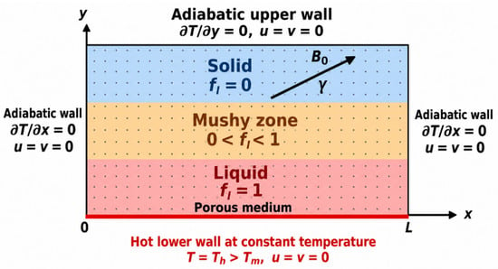
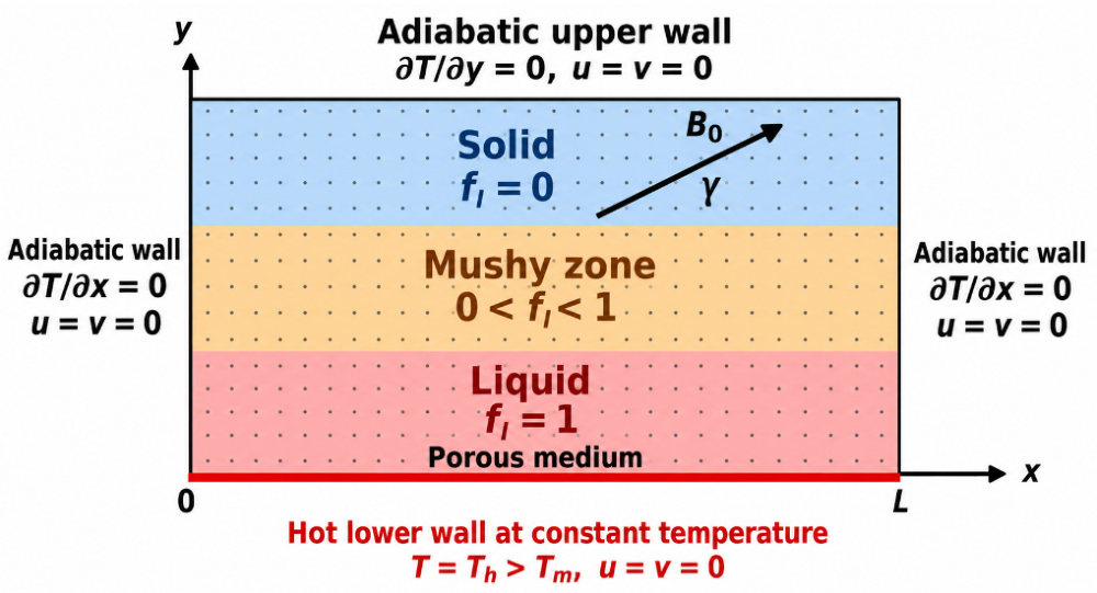
Consider the transient melting of a Williamson phase change material inside a two-dimensional rectangular enclosure of length L and height H, as illustrated in Figure 1. The horizontal and vertical coordinates are denoted by x and y, respectively, with the origin at the lower-left corner. The enclosure contains a stationary, homogeneous, and isotropic porous medium saturated with PCM. Initially, the PCM is completely solid and has a uniform temperature Ti < Ts, where Ts is the solidus temperature. At t > 0, the lower wall is maintained at a constant temperature Th > Tl, where Tl is the liquidus temperature.
Figure 1.
Schematic of the physical model and boundary conditions.
The upper wall and both vertical walls are thermally insulated. All walls are stationary, impermeable, and satisfy the no-slip condition. Heating produces a liquid region adjacent to the lower wall. Buoyancy-driven motion develops as melting proceeds. Gravity acts vertically downward, while a uniform magnetic field of magnitude B0 is applied at an angle γ to the horizontal direction. The two-dimensional approximation assumes negligible out-of-plane variations and provides a simplified framework for examining parameter effects on convection and melting. Front and rear end-wall effects and three-dimensional circulation are therefore excluded, and quantitative application to practical storage systems requires three-dimensional validation. The analysis adopts the following assumptions:
- •
- The flow is two-dimensional, transient, laminar, and incompressible.
- •
- The liquid PCM follows the Williamson shear-thinning model.
- •
- Density variations are neglected except in the buoyancy term.
- •
- Solid and liquid densities are taken as equal, so melting does not change the occupied volume.
- •
- The porous matrix and PCM are in local thermal equilibrium.
- •
- The porous region is represented by a simplified effective-continuum Brinkman–Darcy model. Porosity effects are incorporated into the effective coefficients; separate porosity corrections to inertia are neglected.
- •
- The magnetic Reynolds number is sufficiently small to neglect the induced magnetic field. No externally imposed electric field is considered.
- •
- Thermal radiation is represented by the linearized Rosseland diffusion approximation.
- •
- Viscous dissipation and Joule heating are included. Heating caused by Darcy drag and mushy-zone damping is neglected.
- •
- Temperature gradients across the mushy zone do not necessarily imply a local temperature difference between the porous matrix and PCM. However, finite interfacial heat exchange may produce thermal lag and slower melting than predicted by LTE when the matrix supplies heat to the PCM. A two-temperature LTNE model is required to quantify this deviation.
For a consistent effective-continuum description, ρ, cp, k, Lh, and σ below denote the effective density, specific heat, thermal conductivity, latent heat per unit effective mass, and electrical conductivity used in the model. Thermophysical properties and Williamson constitutive parameters are assumed temperature-independent to isolate parameter effects, while apparent viscosity remains shear-rate dependent. Local thermal equilibrium assumes sufficiently rapid heat exchange between the porous matrix and PCM to maintain approximately equal local temperatures. These approximations require reassessment for strong temperature-dependent property variations or rapid melting, where a local thermal non-equilibrium model may be necessary.
2.2. Williamson Constitutive Model
The velocity vector and material derivative are defined as
The extra-stress tensor is
where μa is the apparent viscosity. For the Williamson model,
in which μ0 and μ∞ are the zero- and infinite-shear-rate viscosities, respectively, and Γ is the Williamson time constant. The shear-rate magnitude is
Here, subscripts denote partial derivatives. The stress components therefore become
2.3. Magnetic Force
The applied magnetic field is
Under the adopted electrical approximation, Ohm’s law gives
The corresponding Lorentz-force components are
The cross terms in Equation (8) are required for an inclined magnetic field.
2.4. Conservation of Mass and Momentum
The incompressible continuity equation is expressed as:
The momentum equations in the horizontal and vertical directions are
Here, K is the porous-medium permeability, β is the thermal expansion coefficient, and Tm is the reference melting temperature. The pressure p is measured relative to the hydrostatic pressure associated with the reference density. No external pressure gradient is imposed. The Darcy resistance in Equations (10) and (11) uses the local apparent viscosity. It remains distinct from the mushy-zone resistance: the former represents the permanent porous matrix, whereas the latter suppresses motion as the PCM solidifies.
The enthalpy–porosity method suppresses motion in the solid and mushy regions through the resistance coefficient
where Cm is the dimensional mushy-zone resistance constant with units of kg m−3 s−1 and ε > 0 is a dimensionless regularization constant that prevents the denominator from vanishing as fl → 0. The liquid fraction fl varies from zero in the solid region to unity in the liquid region.
2.5. Enthalpy and Energy Equation
The specific total enthalpy is expressed as
The liquid fraction is related to temperature by
Accordingly, fl = 0 represents fully solid PCM; fl = 1 corresponds to completely molten; and 0 < fl < 1 defines the mushy region. The energy balance is written in conservative enthalpy form as
2.6. Viscous Dissipation and Joule Heating
Thus, Joule heating depends on the velocity component perpendicular to the magnetic field. The Rosseland radiative heat flux is
where σ* is the Stefan–Boltzmann constant and k* is the mean absorption coefficient. When temperature differences are sufficiently small relative to the absolute reference temperature Tm
The Rosseland approximation requires an optical thickness k*H >> 1, while the linearization of T4 requires ΔT/Tm<<1, with temperatures expressed in kelvin. These conditions are assumed rather than demonstrated for a specific PCM–porous matrix system. The radiation results are therefore conditional on these assumptions, which represent a limitation of the present model.
Radiative diffusion is included in both coordinate directions, consistent with the two-dimensional temperature field. Substituting Equations (13) and (18) into Equation (15) gives
Equation (19) retains both storage and transport of latent enthalpy. An implementation that retains only fl,t must explicitly justify neglecting latent-enthalpy advection.
2.7. Initial and Boundary Conditions
Initially, the PCM is stationary and completely solid:
For t > 0, the boundary conditions are
The temperature jump at the lower wall represents sudden heating at t = 0+. No additional conditions ut = vt = 0 are imposed. Because the enclosure is closed, pressure is determined up to an additive constant. A convenient reference is
Dimensionless quantities are specified by [18]:
The dimensionless local resistance coefficient, apparent viscosity and stress tensor are
Here, (We) is the Williamson parameter, and (G) is the dimensionless shear-rate magnitude. The viscosity ratio is γμ, and η denotes the dimensionless apparent viscosity. Substituting these variables into the governing equations yields the dimensionless momentum and energy equations, presented in Equations (25)–(27). For simplicity, the overbars denoting dimensionless variables are omitted:
The resulting formulation is governed by several important dimensionless parameters, including the Prandtl number (Pr), Grashof number (Gr), Stefan number (St), Eckert number (Ec), magnetic parameter (M), and radiation parameter (Rd). The consistent dimensionless liquid-fraction relation is
The initial and boundary conditions become
2.8. Engineering Performance
The engineering quantities of interest, the local skin-friction coefficient, and local Nusselt number are defined as follows:
The average skin-friction coefficient, average Nusselt number, and average liquid fraction are
The dimensionless stream function is defined by
3. Numerical Methodology
3.1. Numerical Discretization
The coupled dimensionless equations are solved using a finite difference method on a uniform Cartesian grid. The computational domain is 0 ≤ x ≤ ϒ and 0 ≤ y ≤ 1, where ϒ = L/H. The spatial derivatives appearing in the governing equations were approximated using second-order central finite difference schemes. For a general variable ϕ, the first- and second-order derivatives are approximated by Equations (34) and (35), respectively:
Time integration was performed using a first-order implicit scheme:
where n and n + 1 denote the previous and current time levels, respectively. Additional calculations with smaller time steps produced negligible changes in the velocity, temperature, and liquid-fraction fields, confirming temporal independence of the reported numerical results. For clarity, let m denote the inner iteration number at the current time level n + 1. This notation is distinct from n, which denotes the physical time level. Starting from the converged solution at time level n, provisional velocity components u* and v* are obtained from the discretized momentum equations using the currently available pressure field.
3.2. Iterative Solution Algorithm
Finite-difference discretization of the governing equations with initial and boundary conditions gives
Thus, the lower wall is maintained at θ = 1, while the remaining walls have zero normal heat flux. At each time step, the nonlinear equations are linearized through Picard iteration. The resulting scalar linear systems are solved using SOR. For the algebraic equation, the update is
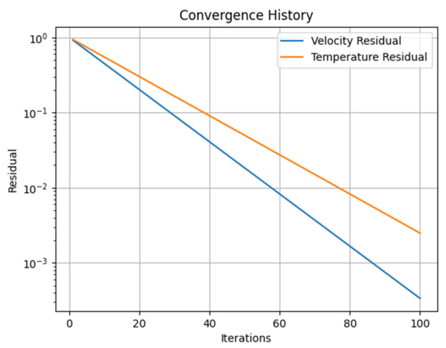
where m is the linear iteration index and ω is the relaxation factor. The relative residual used to monitor convergence is defined by Equation (44). Figure 2 presents the convergence characteristics of the numerical procedure. Figure 2 (single-panel figure showing the velocity and temperature residual convergence).
where ϕ represents the dependent variable and (m) denotes the iteration number. The previous time-level solution provides the initial estimate. The viscosity and resistance coefficients are updated, followed by the momentum solution, pressure correction, and enthalpy solution. This sequence is repeated until the coupled system converges. Following the grid and time-step convergence studies, a uniform 100 × 100 computational grid and a dimensionless time step of Δt = 10−4 are adopted, and simulations were advanced to t = 1. The iterative process for solving the discrete equations is initialized using the prescribed initial and boundary conditions. At each time step (k + 1)th level, the initial values of velocities and temperature from the previous time level t = tk are utilized. MATLAB R20XX (The MathWorks, Inc., Natick, MA, USA) was selected for its efficient matrix operations and flexibility in implementing the coupled equations through a custom finite-difference scheme. A simulation required approximately 45 min; this runtime depends on the hardware, grid, time step, and convergence tolerance. No computational speed advantage over ANSYS Fluent or COMSOL is claimed.
Figure 2.
Convergence of velocity and temperature residuals.
3.3. Grid Independence and Convergence Analysis
The temporal sensitivity is assessed by comparing the average liquid fraction and local Nusselt number for three different time steps on a fixed computational grid at the same final simulation time. The corresponding results are presented in Table 1.
Table 1.
Time-step convergence of the average liquid fraction and local Nusselt number.
Reducing the time step from 10−4 to 5 × 10⁻⁵ changes the average liquid fraction and local Nusselt number by approximately 0.15% and 0.16%, respectively, relative to the finer time-step results. Although the variation in the average liquid fraction between 2 × 10⁻⁴ and 10−4 is approximately 2.47%, the considerably smaller changes obtained with further refinement indicate improved temporal consistency. Therefore, a dimensionless time step of 10−4 is selected as a reasonable compromise between numerical accuracy and computational cost.
The grid-independence study is performed using four computational meshes (40 × 40, 60 × 60, 80 × 80, and 100 × 100) to investigate the influence of spatial resolution on the numerical results. As presented in Table 2, the local Nusselt number increases from 2.83 to 3.12, whereas the local skin-friction coefficient decreases from 0.820 to 0.735 with successive mesh refinement. Similarly, the average liquid fraction decreases from 0.86 to 0.80. Refining the mesh from 80 × 80 to 100 × 100 results in relative changes of approximately 0.64%, 1.50%, and 1.25% in the local Nusselt number, skin-friction coefficient, and average liquid fraction, respectively, using the finest-grid results as references. These relatively small variations indicate that the 100 × 100 mesh provides adequate spatial resolution for the present simulations. Consequently, the 100 × 100 grid is selected for subsequent numerical investigations.
Table 2.
Grid independence study for the present numerical simulations.
The convergence history of the numerical algorithm is further examined by monitoring the velocity and temperature residuals over successive iterations. As illustrated in Figure 2, both residuals decrease continuously with increasing iteration number, indicating stable convergence behaviour of the numerical solution. After 100 iterations, the velocity and temperature residuals reach approximately 3.5 × 10⁻⁴ and 2.5 × 10⁻³, respectively. This decreasing residual behaviour demonstrates the progressive reduction in numerical errors during the iterative solution procedure.
3.4. Model Validation
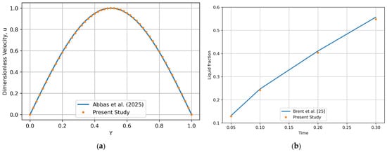
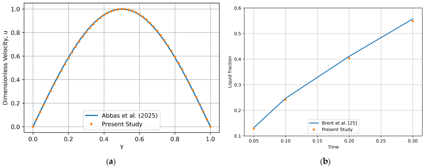
The numerical implementation was assessed through limiting-case comparisons with Abbas et al. [18] and Brent et al. [25]. For the velocity comparison, phase change, porous-medium resistance, magnetic effects, thermal radiation, and Williamson non-Newtonian effects were neglected. The profiles in Figure 3a closely overlap over 0 ≤ y ≤ 1, with zero velocity at both boundaries and a maximum dimensionless velocity of approximately u = 1.0 at y = 0.5. For the melting comparison in Figure 3b, viscous dissipation was additionally neglected, with Gr = 104, Pr = 6.2, and St = 0.2. At times 0.05, 0.10, 0.20, and 0.30, the present liquid fractions are 0.129, 0.242, 0.404, and 0.548, compared with the supplied reference values of 0.132, 0.247, 0.411, and 0.557, respectively. The corresponding relative differences are 2.27%, 2.02%, 1.70%, and 1.62%. The comparisons show good agreement, supporting the accuracy of the present numerical implementation for the tested limiting-case flow and melting problems.
Figure 3.
Comparison of present results with literature data: (a) velocity profiles against Abbas et al. [18] and (b) liquid-fraction evolution against Brent et al. [25].
4. Results and Discussion
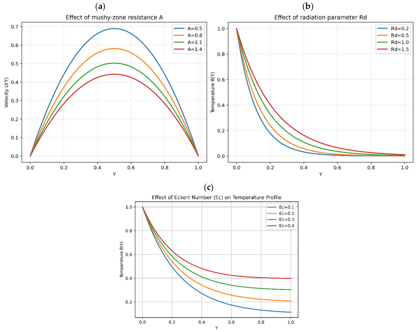
The present study provides a dimensionless parametric investigation of Williamson non-Newtonian PCM melting in a porous-enclosure model under buoyancy-driven natural convection, an inclined magnetic field, thermal radiation, and viscous dissipation. The momentum and energy equations are coupled with the enthalpy–porosity formulation to describe the solid–liquid phase transition. Results are examined through velocity contours, streamlines, temperature distributions, liquid-fraction evolution, and melting-front progression. The effects of the Williamson parameter (We), magnetic parameter (M), radiation parameter (Rd), Eckert number (Ec), Darcy number (Da), Stefan number (St), mushy-zone resistance parameter (A), and Grashof number (Gr) are assessed using the skin-friction coefficient (Cf), Nusselt number (Nu), and average liquid fraction . The baseline values are Gr = 104, Pr = 6.2, We = 0.04, M = 1, Da = 10−2, Ec = 0.1, Rd = 0.5, A = 0.8, and St = 0.2. The values A = 0.5, 0.8, 1.1, and 1.4 represent the dimensionless mushy-zone resistance parameter defined in Equation (23), with all other parameters held at their baseline values during this variation.
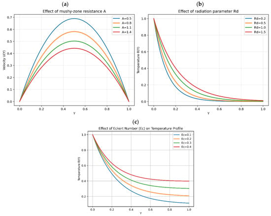
The impact of the mushy-zone resistance parameter A is illustrated in Figure 4a through velocity profiles. It is observed that increasing A significantly suppresses the velocity within the domain. the peak velocity decreases from approximately 0.69 at A = 0.5 to 0.44 at A = 1.4, indicating weaker circulation. This damping is strongest where the liquid fraction is low and vanishes in fully liquid regions where fl = 1, although changes in the surrounding flow can still affect velocity there. The effect of the radiation parameter Rd on the temperature field is depicted in Figure 4b. As Rd increases from 0.2 to 1.5, the temperature distribution increases significantly due to enhanced radiative heat transfer. The influence of viscous dissipation, represented by the Eckert number Ec, is shown in Figure 4c. Increasing Ec leads to a rise in temperature throughout the domain due to the conversion of kinetic energy into thermal energy. This effect is particularly pronounced near the walls, where velocity gradients are high. The influence of the Darcy number on the computed flow and thermal fields is discussed later in this section, with the corresponding skin-friction coefficient, Nusselt number, and average liquid fraction reported in Table 3.
Figure 4.
(a–c). Influence of (a) mushy-zone parameter A on velocity profile and (b) thermal radiation Rd, and (c) Eckert number Ec on temperature distribution.
Table 3.
Variation in skin-friction coefficient, Nusselt number, and average liquid fraction for different physical parameters at t = 1.
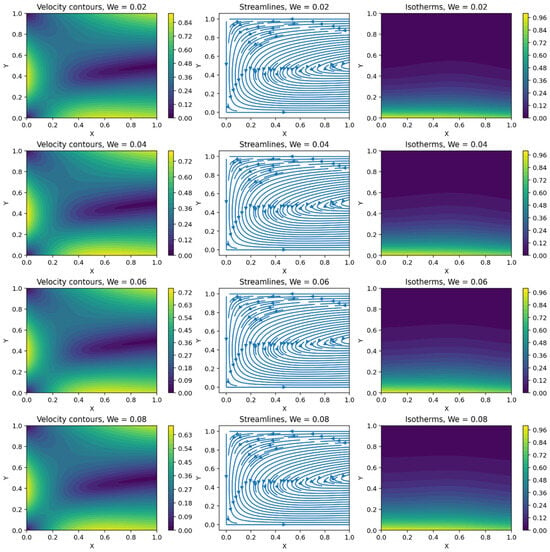
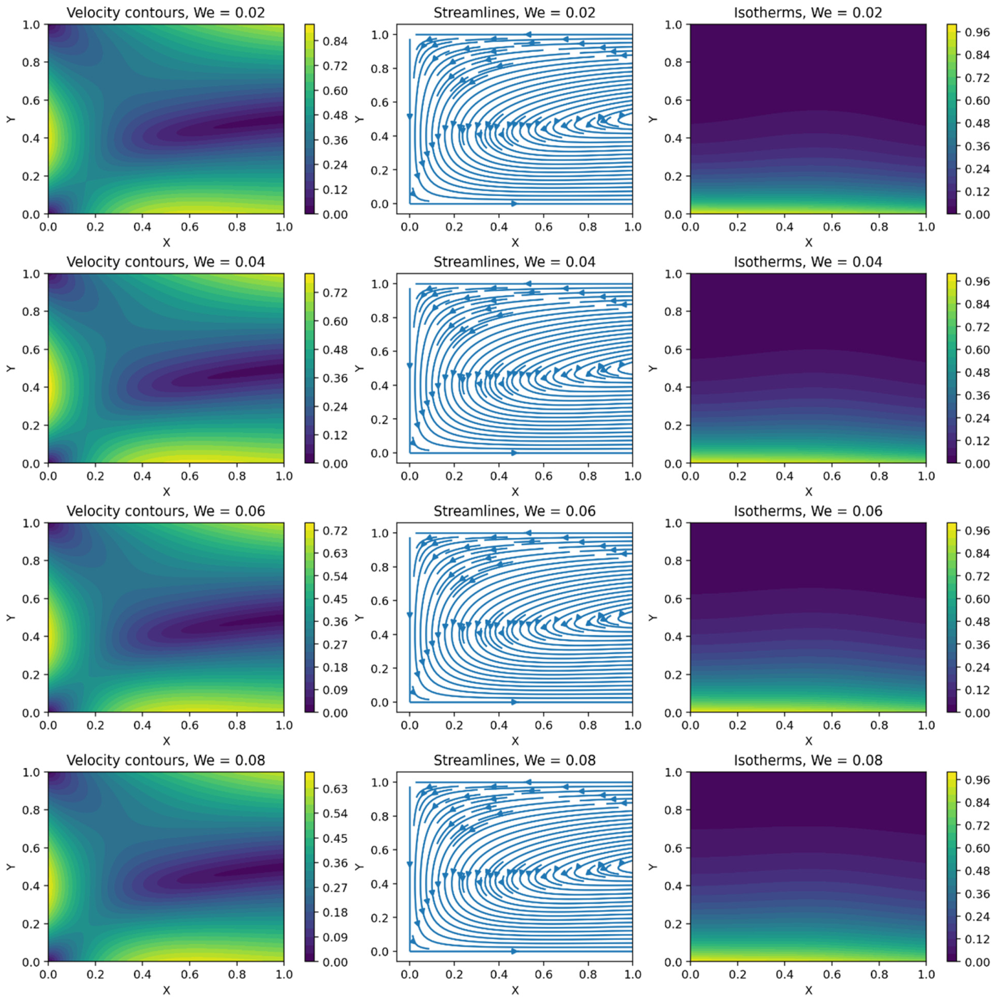
The influence of the Williamson parameter on the velocity contours, streamlines, and temperature distributions is presented in Figure 5. An increase in We corresponds to stronger non-Newtonian behavior and enhanced shear-dependent viscosity. Consequently, the effective flow resistance increases, which suppresses fluid motion and weakens the buoyancy-induced circulation within the enclosure. This reduction in convective transport leads to lower velocity magnitudes and weaker streamlines. Because convection is diminished, thermal energy accumulates within the PCM, resulting in thicker thermal boundary layers and higher temperatures throughout the cavity. The reduced convective heat transfer causes a decrease in the Nusselt number, while the melting process becomes slower due to weaker circulation and reduced heat transport from the heated wall into the bulk PCM.
Figure 5.
Effect of We on velocity contours, streamlines, and isotherms in the porous PCM enclosure for We = 0.02, 0.04, 0.06, and 0.08.
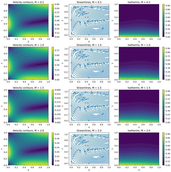
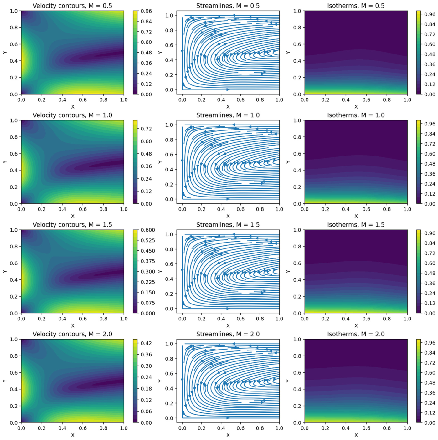
Figure 6 presents the effect of the magnetic parameter M on the flow and thermal fields for M = 0.5, 1.0, 1.5, and 2.0. A clear suppression of the velocity field occurs with increasing M. The interaction between the electrically conducting liquid PCM and the externally applied magnetic field generates a Lorentz force that opposes fluid motion. Increasing the magnetic parameter therefore introduces stronger electromagnetic damping. The streamline patterns confirm the weakening of the recirculating flow as M increases. Since natural convection is responsible for transporting thermal energy away from the heated region, suppression of the velocity field reduces convective heat transfer. An inclined magnetic field could, in principle, be generated using an oriented permanent-magnet assembly or electromagnet, although installation size, cost, and electromagnet power and cooling requirements may constrain implementation. The present model prescribes an idealized field; practical feasibility requires separate assessment of the magnet system and PCM electrical conductivity.
Figure 6.
Effect of M on velocity contours, streamlines, and isotherms in the porous PCM enclosure for M = 0.5, 1.0, 1.5, and 2.
The isotherms consequently become more conduction-dominated, with thermal energy concentrated more strongly near the heated region. This behavior is also reflected in the engineering quantities. Increasing M from 0.5 to 2.0 reduces Cf from 0.812 to 0.638 and Nu from 3.18 to 2.97. Over the same range, the average liquid fraction decreases from 0.86 to 0.69. Thus, stronger magnetic damping not only suppresses fluid circulation but also delays the propagation of the melting front.
The influence of porous-medium permeability is illustrated in Figure 7 through variations in the Darcy number Da. Increasing Da from 10−5 to 10−2 corresponds to increasing permeability and therefore decreasing resistance imposed by the porous matrix. For the baseline case, Da = 10−2 represents a highly permeable porous matrix with relatively low flow resistance, corresponding to a permeability scale of K ≈ 10−2H2.
Figure 7.
Effect of Da on velocity contours, streamlines, and isotherms for Da = 10−5, 10−4, 10−3, 10−2.
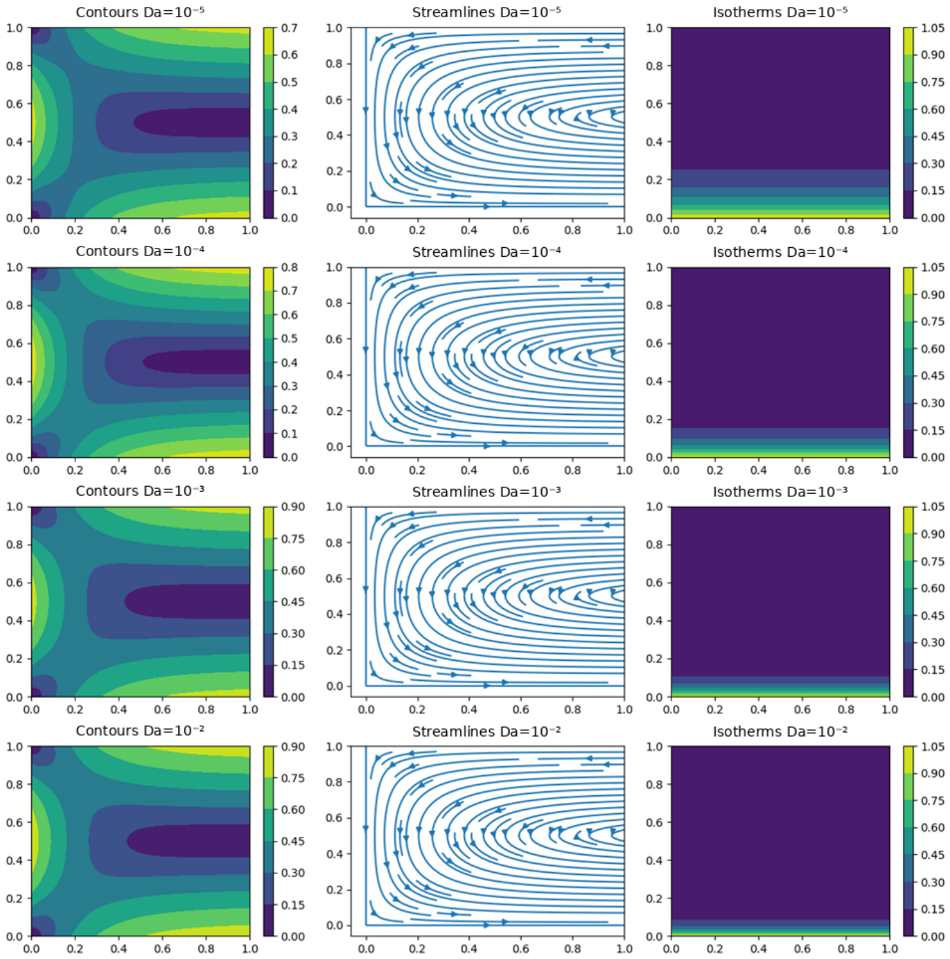
As a result, the liquid PCM is able to circulate more freely, producing higher velocity magnitudes and stronger recirculating motion. The enhanced circulation modifies the thermal field by transporting heat more effectively from the heated boundary into the molten region. The isotherms become more strongly compressed near the heated wall, indicating an increased wall-temperature gradient and therefore an enhanced heat-transfer rate. Improved fluid circulation also transfers energy more efficiently toward the solid–liquid interface and promotes melting. The quantitative data demonstrate this enhancement clearly. As Da increases from 10−5 to 10−2, Cf increases from 0.600 to 0.746, Nu increases from 2.35 to 3.10, and the average liquid fraction rises from 0.51 to 0.81. Thus, permeability plays a beneficial role in both natural-convection strength and thermal-storage charging performance.
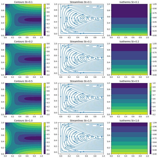
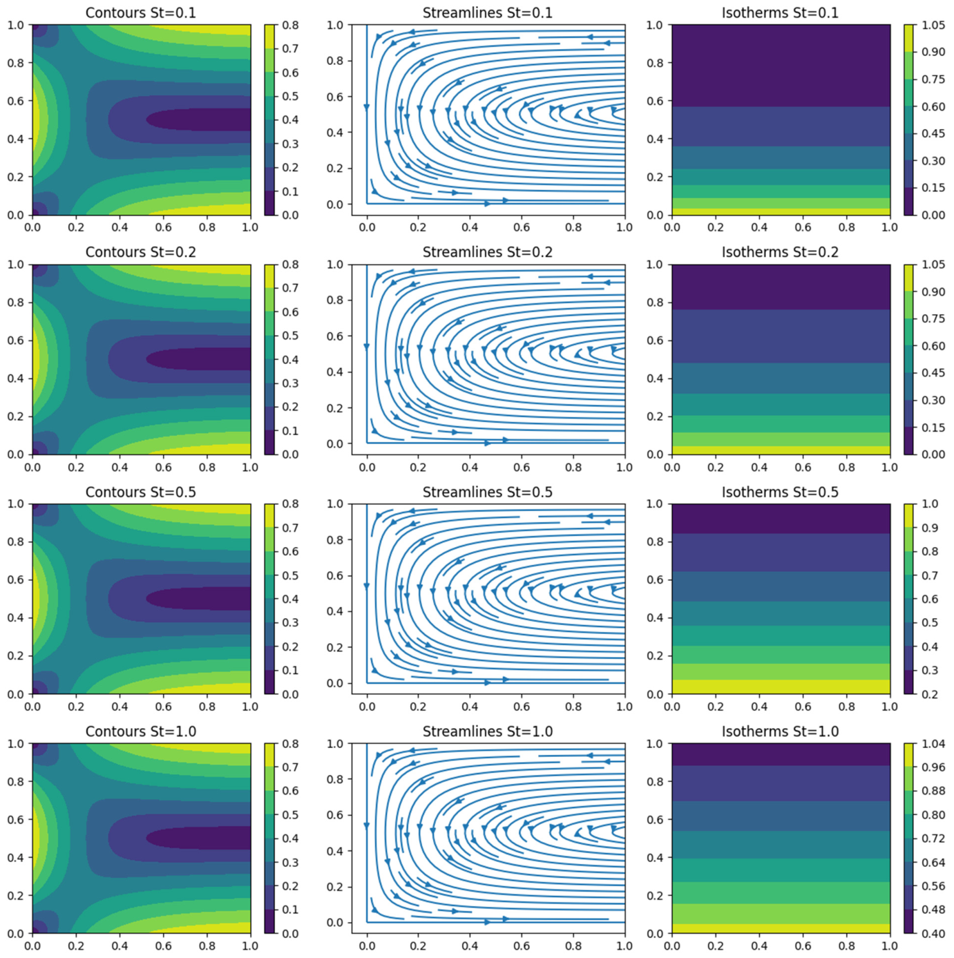
Figure 8 illustrates the influence of the Stefan number St for St = 0.1, 0.2, 0.5, and 1.0. The Stefan number represents the relative importance of sensible heating compared with the latent heat associated with phase transition. A larger value of St corresponds to a smaller latent-heat requirement relative to the available sensible thermal energy. The isotherms show a pronounced increase in temperature penetration as St increases. At relatively small St, a substantial fraction of the supplied thermal energy is consumed in overcoming the latent heat of fusion, which limits the temperature rise. At larger St, less energy is required for the phase transition relative to sensible heating, and thermal energy spreads farther into the PCM domain. Consequently, melting proceeds more rapidly. Table 3 confirms that the Stefan number has a particularly strong influence on thermal and phase-change performance. Increasing St from 0.1 to 1.0 increases Cf from 0.684 to 0.891, Nu from 2.89 to 3.78, and the average liquid fraction from 0.68 to 0.99. Among the parameter ranges examined in Table 3, St produces one of the strongest enhancements in the melting response. The observed sensitivity to St applies only to the ranges examined. In practical systems, St is constrained by the PCM properties and allowable operating temperatures; changing it may also affect other dimensionless parameters.
Figure 8.
Effect of St on velocity contours, streamlines, and isotherms for St = 0.1, 0.2, 0.5, and 1.
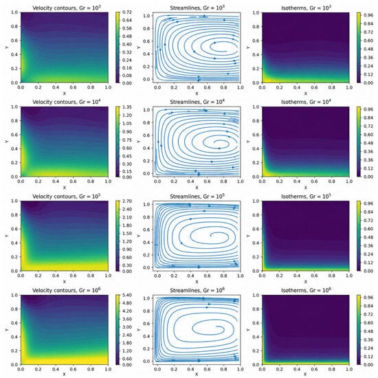
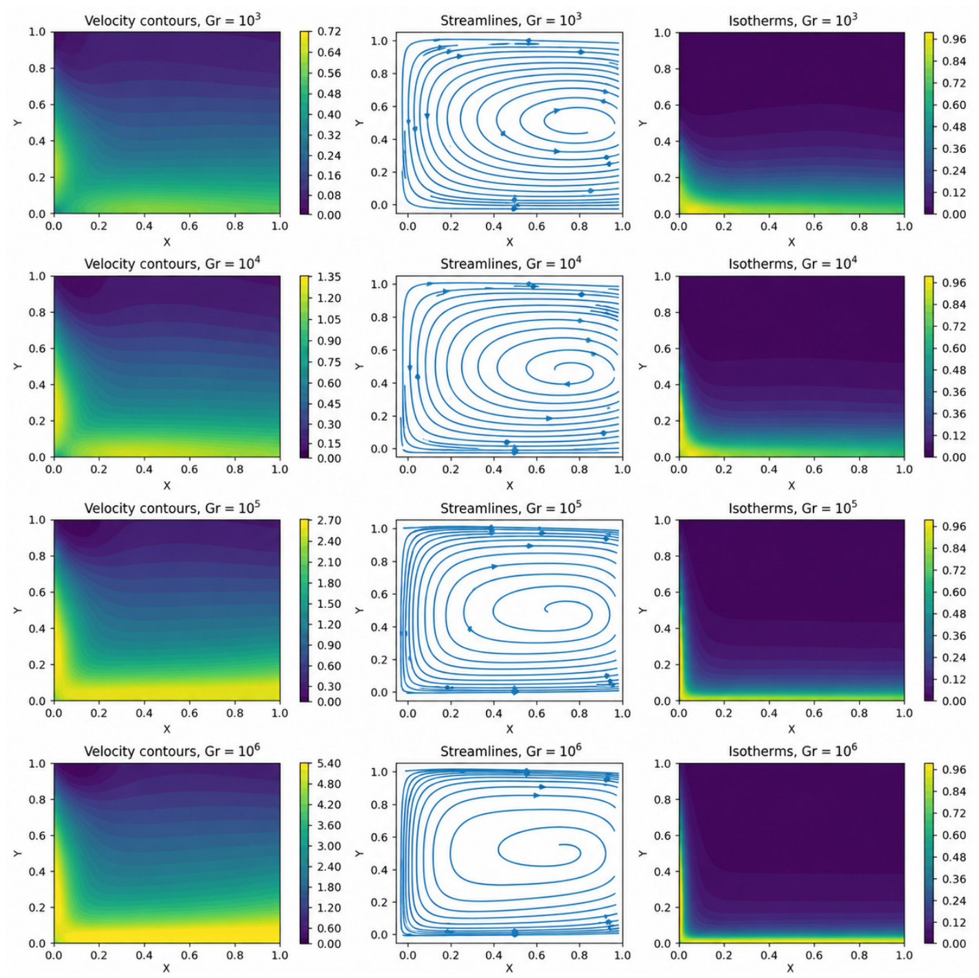
Figure 9 illustrates the influence of the Grashof number on the velocity contours, streamlines, and isotherms. It is observed that increasing (Gr) significantly enhances the buoyancy force generated by thermal gradients, thereby strengthening the natural convection flow. Consequently, the velocity magnitude increases throughout the enclosure, as evidenced by the higher contour levels and intensified circulation patterns. The streamline plots reveal the formation of a stronger primary vortex that occupies a larger portion of the cavity as (Gr) increases, indicating enhanced fluid mixing and recirculation. Moreover, the isotherms become progressively distorted from their conductive configuration, demonstrating the transition from conduction-dominated to convection-dominated heat transfer.
Figure 9.
Effect of Grashof number (Gr = 103, 104, and 105) on velocity contours, streamlines, and isotherms.
At lower (Gr), the relatively parallel temperature contours are consistent with weaker convection; at higher (Gr), their deformation indicates greater redistribution of heat by fluid motion. These qualitative changes should not be interpreted as a proportional enhancement of wall heat transfer. Specifically, increasing (Gr) from 103 to 105 raises Nu from 2.96 to 3.22 (8.8%) and Cf from 0.742 to 0.758 (2.2%), whereas the average liquid fraction increases from 0.76 to 0.88. Thus, the reported results show stronger circulation and increased melting extent, accompanied by a modest improvement in wall heat transfer.
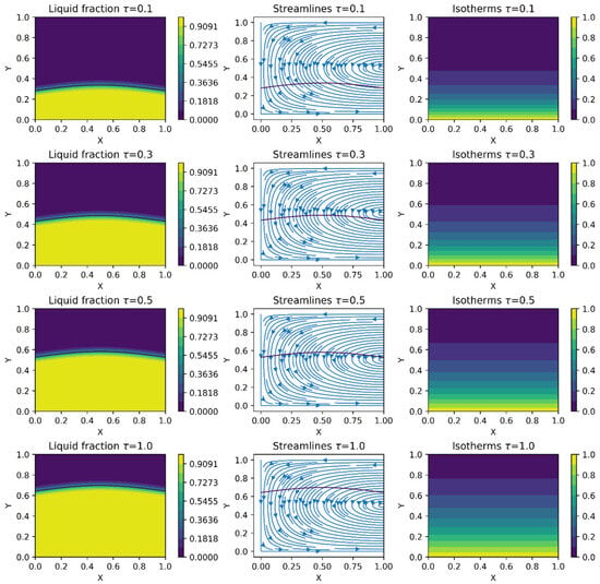
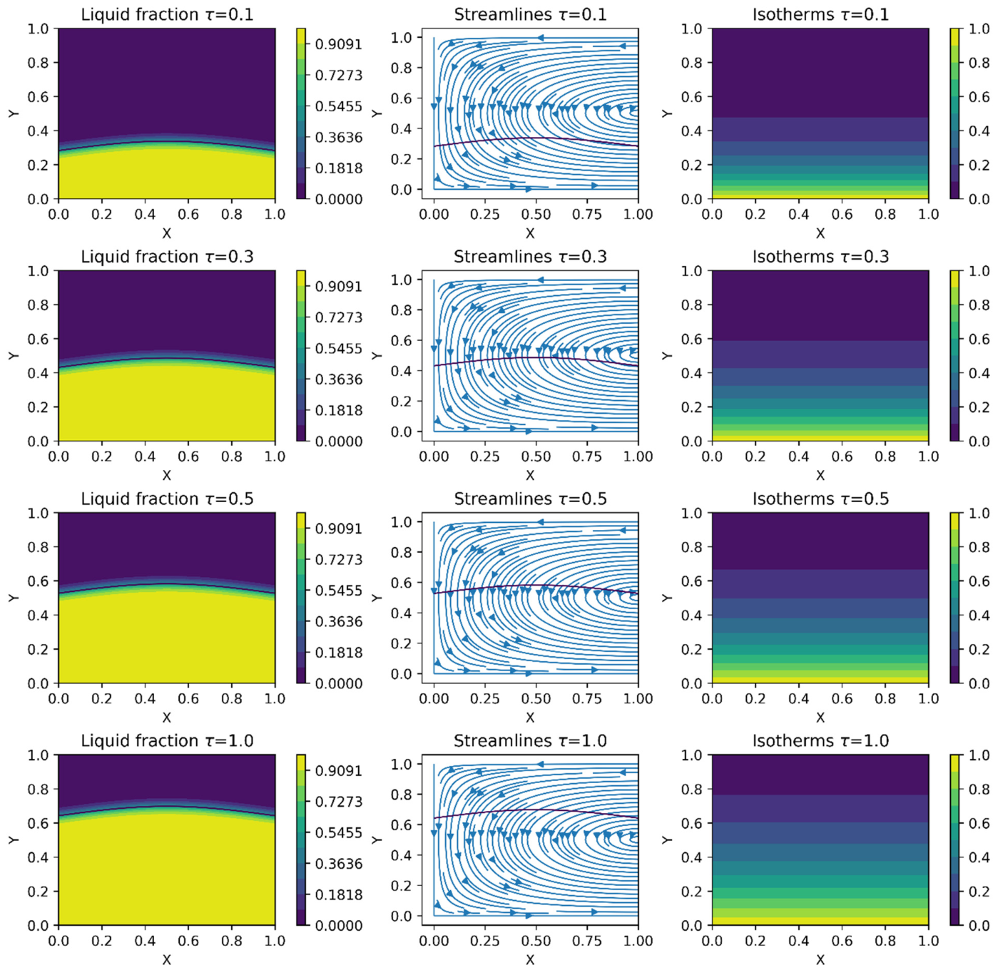
The temporal evolution of the liquid fraction is illustrated in Figure 10. At τ = 0, the PCM is entirely solid, with (fl = 0) and a uniform temperature (Ti < Ts), consistent with Equations (20) and (29). After heating begins, a thin liquid layer develops adjacent to the heated wall, while most of the PCM remains solid. As time progresses, heat penetrates farther into the domain, the liquid region expands, and the solid–liquid interface moves away from the heated boundary. At τ = 1, the baseline average liquid fraction reaches 0.81, indicating substantial but incomplete melting, with approximately 19% of the PCM remaining solid. The evolution is consistent with an initially conduction-led melting process and an increasing contribution from convection as the liquid region develops. From a thermal energy storage perspective, the increasing liquid fraction represents progressive charging and greater latent-energy storage. However, this increase alone does not establish improved storage efficiency or demonstrate an enhancement attributable to the porous medium.
Figure 10.
Temporal evolution of the liquid fraction on velocity contours, streamlines, and isotherms.
Table 3 summarizes the combined effects of the governing parameters on the skin-friction coefficient Cf, Nusselt number Nu, and average liquid fraction fl. Increasing the Williamson parameter (We), magnetic parameter (M), and mushy-zone resistance parameter (A) decreases these quantities, indicating reduced wall shear, wall heat transfer, and melting extent. Conversely, increasing (Da), (Rd), (Ec), (St), and (Gr) increases the reported quantities. Specifically, increasing (Gr) from 103 to 105 raises (Nu) from 2.96 to 3.22 (8.8%) and (Cf) from 0.742 to 0.758 (2.2%), while (fl) increases from 0.76 to 0.88. These results indicate modest changes in the wall quantities alongside a larger change in melting extent. Stronger circulation does not necessarily produce a proportional increase in wall heat transfer because energy transport also depends on the evolving temperature field and phase-change interface. The contribution of latent-heat absorption to this behavior requires assessment using transient heat-transfer results. Among the parameter ranges examined, (St) produces the largest increases in (Nu) and (fl), from 2.89 to 3.78 and from 0.68 to 0.99, respectively.
5. Conclusions
This study examined the unsteady melting behavior of a Williamson non-Newtonian phase change material (PCM) embedded in a porous medium under the combined effects of an inclined magnetic field, thermal radiation, viscous dissipation, and porous resistance. The enthalpy–porosity method was employed to model the solid–liquid phase transition, while the governing momentum and energy equations were solved numerically using the finite difference method. The influence of key physical parameters on flow characteristics, heat transfer, and melting performance was analyzed through velocity contours, streamlines, isotherms, liquid fraction evolution, skin-friction coefficient, and Nusselt number. The major findings are summarized as follows:
- •
- Increasing the Williamson parameter suppresses fluid motion due to enhanced non-Newtonian resistance. Consequently, the skin-friction coefficient, Nusselt number, and average liquid fraction decrease, indicating weaker convective heat transfer and slower melting progression.
- •
- Increasing the magnetic parameter strengthens electromagnetic damping and suppresses circulation. The associated decreases in the Nusselt number and average liquid fraction indicate reduced wall heat transfer and melting extent.
- •
- Increasing the Darcy number reduces porous resistance and promotes fluid motion. Higher permeability is associated with increased skin-friction and Nusselt numbers and a larger molten fraction.
- •
- Increasing the mushy-zone resistance parameter suppresses motion in the partially melted region. The average liquid fraction decreases from 0.87 to 0.70 over the examined range, representing a relative reduction of approximately 19.5%.
- •
- Increasing the radiation parameter raises the interior temperature and promotes thermal penetration.
- •
- Increasing the Eckert number strengthens the dissipative heating contributions represented in the energy equation. The computed results show higher temperatures, Nusselt numbers, and liquid fractions.
- •
- The Stefan number produces the largest increases in the Nusselt number and average liquid fraction.
- •
- Increasing the Grashof number enhances buoyancy-driven flow, strengthens vortex formation and fluid mixing, and promotes the transition from conduction-dominated to convection-dominated heat transfer.
The present model has been assessed against simplified benchmark problems; however, quantitative validation against published non-Newtonian or nanoparticle-enhanced PCM melting results remains outstanding. Future work will evaluate appropriate limiting cases under matched conditions, using average liquid fraction at identical dimensionless times and total melting time as comparison measures. Further validation will also address the coupled magnetic and porous-medium effects. The current findings describe parameter-dependent trends within the adopted model, while material-specific design applications require additional numerical and experimental assessment. Potential extensions include temperature-dependent properties, nanoparticle-enhanced PCMs and three-dimensional configurations.
Author Contributions
H.K.: Conceptualization; methodology; formal analysis; investigation; writing—original draft preparation; writing—review and editing. A.I.: Formal analysis; investigation; writing—review and editing; supervision; funding. All authors have read and agreed to the published version of the manuscript.
Funding
The authors acknowledge financial support from NSERC-Discovery Grant (RGPIN-2025-04831 for Adrian Ilinca).
Data Availability Statement
Data is available from the corresponding author.
Conflicts of Interest
The authors declare no conflicts of interest. The funders had no role in the design of the study; in the collection, analysis, or interpretation of data; in the writing of the manuscript; or in the decision to publish the results.
Declaration of Generative AI and AI-Assisted Technologies in the Writing Process
During the preparation of this manuscript, ChatGPT5 (OpenAI) was used to assist with language editing, readability improvement, restructuring of selected sections, and drafting support for limited portions of the text. The authors performed all scientific content, interpretation, critical evaluation, and final editing and take full responsibility for the manuscript.
Nomenclature
| A | Dimensionless mushy-zone resistance parameter | S(fl) | Local mushy-zone resistance coefficient |
| Cm | Dimensional mushy-zone resistance constant | St | Stefan number |
| B0 | Magnetic field strength | T | Temperature |
| Cf | Skin friction coefficient | Tm | Melting temperature |
| cp | Specific heat capacity | Th | Hot wall temperature |
| Da | Darcy number | t | Time |
| Ec | Eckert number | Dimensionless velocity components | |
| fl | Liquid fraction | eff | Effective property |
| g | Gravitational acceleration | We | Williamson parameter |
| H | Enclosure height | l | Liquid phase |
| k | Thermal conductivity | x,y | Cartesian coordinates |
| L | Characteristic length | α | Inclination angle |
| Lh | Latent heat of fusion | β | Thermal expansion coefficient |
| M | Magnetic parameter | Γ | Williamson parameter |
| Nu | Nusselt number | θ | Dimensionless temperature |
| p | Dimensionless pressure | μ | Dynamic viscosity |
| Pr | Prandtl number | μeff | Effective viscosity |
| qr | Radiative heat flux | ρ | Density |
| Rd | Radiation parameter | s | Solid phase |
| Average liquid fraction | J | Electric current density | |
| keff | Effective thermal conductivity | K | Permeability of porous medium |
| k* | Mean absorption coefficient | ||
| p | Pressure | Dimensional time | |
| Ti | Initial temperature | Tl | Liquidus temperature |
| T∞ | Reference temperature | Ts | Solidus temperature |
| u, v | Velocity components | U0 | Characteristic velocity |
| Greek Symbols | |||
| Symbol | Description | Unit | |
| Γ | Williamson time constant | s | |
| γ | Magnetic field inclination angle | rad | |
| Δt | Time-step size | s | |
| Δx | Grid spacing in the x-direction | m | |
| Δy | Grid spacing in the y-direction | m | |
| ε | Regularization constant in the mushy-zone resistance term | – | |
| εp | Porosity of porous medium | – | |
| θ | Dimensionless temperature | – | |
| μ | Dynamic viscosity | Pa s | |
| μ0 | Zero-shear-rate viscosity | Pa s | |
| μ∞ | Infinite-shear-rate viscosity | Pa s | |
| μeff | Effective viscosity | Pa s | |
| ρ | Density | kg m−3 | |
| σ | Electrical conductivity | S m−1 | |
| σ∗ | Stefan–Boltzmann constant | W m−2 K−4 | |
| τij | Stress tensor | Pa | |
| Φ | Viscous dissipation function | W m−3 | |
| ψ | Stream function | m2 s−1 | |
| Subscripts | |||
| Subscript | Meaning | ||
| eff | Effective property | ||
| h | Hot wall | ||
| i | Initial condition | ||
| l | Liquid phase | ||
| m | Melting condition | ||
| pcm | Phase change material | ||
| ref | Reference value | ||
| s | Solid phase | ||
| Ambient condition | |||
| Abbreviation | |||
| Abbreviation | Description | ||
| CFD | Computational Fluid Dynamics | ||
| FDM | Finite Difference Method | ||
| MHD | Magnetohydrodynamics | ||
| PCM | Phase Change Material | ||
| SOR | Successive Over-Relaxation | ||
| TES | Thermal Energy Storage | ||
References
- Farid, M.M.; Khudhair, A.M.; Razack, S.A.K.; Al-Hallaj, S. A review on phase change energy storage: Materials and applications. Energy Convers. Manag. 2004, 45, 1597–1615. [Google Scholar] [CrossRef] [Scilit]
- Zeng, C.; Yuan, Y.; Haghighat, F.; Panchabikesan, K.; Joybari, M.M.; Cao, X.; Klimeš, L. Application of PCM-based thermal energy storage system in buildings: A state of the art review on the mathematical modeling approaches and experimental investigations. J. Therm. Sci. 2022, 31, 1821–1852. [Google Scholar] [CrossRef] [Scilit]
- Yu, C.; Shen, D.; Wang, W.; Song, X.; Xin, J.; Cai, L.; Tu, J. Numerical study on the thermal performance of phase change materials wall by radiative cooling. Appl. Therm. Eng. 2022, 215, 119013. [Google Scholar] [CrossRef] [Scilit]
- Zhao, C.; Wang, J.; Sun, Y.; He, S.; Hooman, K. Fin design optimization to enhance PCM melting rate inside a rectangular enclosure. Appl. Energy 2022, 321, 119368. [Google Scholar] [CrossRef] [Scilit]
- Alomari, M.A.; Ali, F.H.; Al-Salami, Q.H.; Hamzah, H.K.; Al-amir, Q.R.; Alyousuf, F.Q.; Ismael, M.A. Numerical analysis of MHD free convection in curvilinear porous enclosure with two active cylinders filled with NE-phase change material. J. Energy Storage 2024, 95, 112602. [Google Scholar] [CrossRef] [Scilit]
- Zhao, Y.; Zhang, P.; Qiu, Y.; Li, Q.; Yan, H.; Wang, Z.; Wu, C. Highly conductive solid-solid phase change composites and devices enhanced by aligned graphite networks for solar/electro-thermal energy storage. DeCarbon 2024, 5, 100051. [Google Scholar] [CrossRef] [Scilit]
- Zhu, J. Viscoplastic and pseudoplastic flows through fractal fractures. Int. J. Non-Linear Mech. 2022, 145, 104107. [Google Scholar] [CrossRef] [Scilit]
- Praharaj, S.; Sharma, R.P. Optimization of heat transfer characteristics in Williamson fluid flow over a permeable Riga surface for advanced engineering applications. Multiscale Multidiscip. Model. Exp. Des. 2025, 8, 324. [Google Scholar] [CrossRef] [Scilit]
- Awais, M.; Salahuddin, T.; Muhammad, S.; Ould Sidi, M. Numerical significance of chemical reactive species and induced heat source along with magnetohydrodynamic radiated Williamson fluid flow on the oscillating plate with porous medium. Int. J. Model. Simul. 2025, 1–15. [Google Scholar] [CrossRef] [Scilit]
- Abbas, Z.; Rizwan, M.; Arslan, M.S.; Rafiq, M.Y.; Rangra, N. Rheological behavior of unsteady Buongiorno nanofluid over a flat surface with variable pressure gradient under slip constraints. Proc. Inst. Mech. Eng. Part N J. Nanomater. Nanoeng. Nanosyst. 2026, 23977914261430149. [Google Scholar] [CrossRef] [Scilit]
- Barnes, H.A. Shear-thickening (“Dilatancy”) in suspensions of nonaggregating solid particles dispersed in Newtonian liquids. J. Rheol. 1989, 33, 329–366. [Google Scholar] [CrossRef] [Scilit]
- Khan, N.A.; Khan, H. A boundary layer flows of non-Newtonian Williamson fluid. Nonlinear Eng. 2014, 3, 107–115. [Google Scholar] [CrossRef] [Scilit]
- Mirzaee, H.; Ahmadi, G.; Rafee, R.; Talebi, F. Physical overview of the instability in laminar wall-bounded flows of viscoplastic and viscoelastic fluids at subcritical Reynolds numbers. J. Heat Mass Transf. Res. 2023, 10, 135–146. [Google Scholar]
- Quran, O.; Maaitah, H.; Alsabagh, A.S.; Elayyan, M.; Duwairi, H.M. Fluid flow and heat transfer characteristics of Williamson fluids flowing in saturated porous media. Adv. Mech. Eng. 2023, 15, 16878132231157159. [Google Scholar] [CrossRef] [Scilit]
- Ellahi, R.; Hassan, M.; Zeeshan, A. Study of natural convection MHD nanofluid by means of single and multi-walled carbon nanotubes suspended in a salt-water solution. IEEE Trans. Nanotechnol. 2015, 14, 726–734. [Google Scholar] [CrossRef] [Scilit]
- Hayat, T.; Shafiq, A.; Alsaedi, A. Hydromagnetic boundary layer flow of Williamson fluid in the presence of thermal radiation and Ohmic dissipation. Alex. Eng. J. 2016, 55, 2229–2240. [Google Scholar] [CrossRef] [Scilit]
- Hamid, A.; Khan, M. Unsteady mixed convective flow of Williamson nanofluid with heat transfer in the presence of variable thermal conductivity and magnetic field. J. Mol. Liq. 2018, 260, 436–446. [Google Scholar] [CrossRef] [Scilit]
- Abbas, Z.; Rafiq, M.Y.; Arslan, M.S.; Rangra, N. Optimizing power and cooling: SOR-based computational analysis of hybrid nanoliquid flow in Darcy porous medium. Results Eng. 2025, 26, 104602. [Google Scholar] [CrossRef] [Scilit]
- Nazeer, M.; Almohammadi, S.M.; Radwan, N.; Ahmad, W. Heat transfer analysis in hydromagnetic two-phase Williamson fluid through tilted channel: Applications of gold and silver nanoparticles in solar thermal energy. ZAMM-J. Appl. Math. Mech. Für Angew. Math. Und Mech. 2025, 105, e202400397. [Google Scholar] [CrossRef] [Scilit]
- Shao, Y.; Arshad, Z.; Radwan, N.; Shah, Z.; Raja, M.A.Z.; Almohammadi, S.M.; Khan, W.A. Investigating the radiative heat transfer analysis of magnetized Cross fluid flow capturing variable properties around paraboloid surface using artificial intelligence stochastic approach. Chaos Solitons Fractals 2025, 191, 115887. [Google Scholar] [CrossRef] [Scilit]
- Li, J.; Peng, Z.; Zhang, H.; Sun, X.; Yan, J.; Jiang, C.; Zhang, Q. Analysis of heat transfer and fluid flow during the melting process of PCM within tubular thermal energy storage unit. Appl. Therm. Eng. 2024, 244, 122681. [Google Scholar] [CrossRef] [Scilit]
- Howell, J.R.; Mengüç, M.P.; Daun, K.; Siegel, R. Thermal Radiation Heat Transfer; CRC press: Boca Raton, FL, USA, 2020. [Google Scholar]
- Dai, H.; Zhu, C.; Liu, Y. Thermal performance of double-layer porous-microchannel with phase change slurry. Appl. Therm. Eng. 2022, 211, 118457. [Google Scholar] [CrossRef] [Scilit]
- Voller, V.R.; Prakash, C. A fixed grid numerical modelling methodology for convection-diffusion mushy region phase-change problems. Int. J. Heat Mass Transf. 1987, 30, 1709–1719. [Google Scholar] [CrossRef] [Scilit]
- Brent, A.D.; Voller, V.R.; Reid, K.T.J. Enthalpy-porosity technique for modeling convection-diffusion phase change: Application to the melting of a pure metal. Numer. Heat Transf. Part A Appl. 1988, 13, 297–318. [Google Scholar] [CrossRef] [Scilit]
- Mahdi, J.M.; Nsofor, E.C. Solidification of a PCM with nanoparticles in triplex-tube thermal energy storage system. Appl. Therm. Eng. 2016, 108, 596–604. [Google Scholar] [CrossRef] [Scilit]
- Sheikholeslami, M. Numerical modeling of nano enhanced PCM solidification in an enclosure with metallic fin. J. Mol. Liq. 2018, 259, 424–438. [Google Scholar] [CrossRef] [Scilit]
- Ullah, S.; Ali, Z.; Pamucar, D.; Khan, Z.A.; Emam, W. Viscoelastic Jeffery-Hamel flow of Oldroyd-B fluid with thermal radiation and heat source in inclined convergent/divergent channels. Case Stud. Therm. Eng. 2025, 73, 106709. [Google Scholar] [CrossRef] [Scilit]
- Chari, F.N.; Jalili, P.; Jalili, B.; Ganji, D.D. MHD Casson non-Newtonian fluid flow in a channel with expanding/contracting porous walls in the presence of thermal radiation. Proc. Inst. Mech. Eng. Part E J. Process Mech. Eng. 2026, 240, 858–872. [Google Scholar] [CrossRef] [Scilit]
- Sarki, M.N.; Aleiro, A.S.; Fakai, A.S.; Hamza, M.M.; Shuaibu, A. Fractional model for Casson fluid flow with thermal radiation effects in a convectively heated channel. Multiscale Multidiscip. Model. Exp. Des. 2026, 9, 136. [Google Scholar] [CrossRef] [Scilit]
- Fadaei, M.; Izadi, M.; Assareh, E.; Ershadi, A. Melting process of PCM with Carreau–Yasuda non-Newtonian behavior in a shell and tube heat exchanger occupied by anisotropic porous medium. Int. J. Numer. Methods Heat Fluid Flow 2022, 32, 3751–3781. [Google Scholar] [CrossRef] [Scilit]

Disclaimer/Publisher’s Note: The statements, opinions and data contained in all publications are solely those of the individual author(s) and contributor(s) and not of MDPI and/or the editor(s). MDPI and/or the editor(s) disclaim responsibility for any injury to people or property resulting from any ideas, methods, instructions or products referred to in the content. |
© 2026 by the authors. Licensee MDPI, Basel, Switzerland. This article is an open access article distributed under the terms and conditions of the Creative Commons Attribution (CC BY) license.