


Abstract
Cascading failures in power systems worldwide are often triggered by short-circuit (SC) faults accompanied by intense high-frequency (HF) electromagnetic transients that can generate non-design-basis electromagnetic interference (EMI) and increase the risk of maloperation of microprocessor-based relay protection and automation (RPA) devices. This paper presents an on-site simulation method for determining the level of HF antiphase EMI in RPA control circuits, based on reproducing the HF component of the short-circuit current using a pulse generator with test current injection into the grounding system. The method was validated at the operating 500 kV Shymkent substation of KEGOC JSC (Republic of Kazakhstan): pulsed electromagnetic disturbances in secondary circuits were measured at the 500 kV and 220 kV switchyards while simulating the HF component of the single-phase-to-ground short-circuit current. It was experimentally established that the level of induced antiphase interference is determined by the impulse resistance of the grounding system and the attenuation coefficient of the disturbance into secondary circuits, and in a number of the investigated circuits the levels rescaled to the HF component of the fault current exceed the 1 kV immunity test level of microprocessor-based devices. The measured impulse resistance of the equipment grounding was 1.8–7.2 Ω, the attenuation coefficient was 2.1–12.7, and the rescaled differential-mode interference reached 1.9 kV (1.5–2.2 kV, taking into account an uncertainty of ±20%). Since the reaction of the terminals was not recorded, these results indicate an increased risk of RPA maloperation due to non-design-basis EMI during short circuits and justify the need to account for this factor when designing grounding systems and configuring relay protection settings.
1. Introduction
1.1. Analysis of Cascading Failures over the Past Decade
Electric power systems (EPS) constitute a structure comprising generating plants, transmission lines, distribution substations, and automated process control systems (APCS) that ensure their reliable operation [1,2]. An important condition for EPS reliability is ensuring the electromagnetic immunity of APCS to various types of electromagnetic disturbances arising during operation under both normal and fault conditions. The adoption of SMART devices, including the trend toward miniaturization of functional components used in microelectronics, leads to a significant reduction in their immunity [3,4,5]. Methods have been developed to improve the interference immunity of SMART APCS; however, they do not always yield a positive effect [6,7,8,9]. All of this indicates a high degree of vulnerability of microprocessor-based relay protection and emergency automation systems.
A high share of renewable energy sources (RES) further aggravates the situation: power converters are built on an electronic component base similar to that of microprocessor-based RPA and are therefore susceptible to the same types of high-frequency interference. Therefore, research is needed to develop comprehensive EMC measures that simultaneously account for the characteristics of RES inverters and the specifics of RPA operation, including analysis of non-design-basis EMI and its effect on power system stability under fault conditions.
Typical causes of such failures [10,11,12] include the disconnection or overloading of transmission lines, short circuits, overvoltages, lightning strikes, poor maintenance, human error, voltage sags, equipment aging and failure, cyberattacks, rapid frequency decline, and others. In the authors’ view, the transition of such failures into cascading ones may be triggered by incorrect operation of microprocessor-based RPA associated with non-design-basis electromagnetic disturbances. The aim of this paper is to determine the level of high-frequency interference induced in the control cables of an electrical substation during short circuits.
Analysis shows that SC faults are the root cause of many major failures [13,14,15]. It should be noted that when the root cause is a thunderstorm, strong wind, a fallen transmission tower, etc., these phenomena almost always result in an SC that is detected by RPA devices. Thus, SC faults account for the majority of all system-wide failures [10,16,17,18,19,20]. For example, between 2015 and 2025 a number of failures occurred in various countries worldwide that were directly or indirectly related to short circuits. Despite significant differences in scale, geography, and infrastructure specifics, all of these incidents share a common feature: a local disturbance of the electrical network mode caused by a short circuit, together with the resulting electromagnetic transients, triggered the cascading disconnection of large sections of the grid or even entire national power systems. The most illustrative cases, demonstrating the possible consequences of SC faults, are reviewed below.
In March 2015, a serious system incident occurred at the Diemen substation (Netherlands), caused by a phase-to-phase SC fault at a 150 kV node. According to [21], the development of the failure coincided with an error by operating personnel during switching operations, which significantly complicated the course of events. On the morning of 27 March, both halves of the substation circuit (lines and transformers) were temporarily interconnected during a routine operation, which initiated a short circuit and the automatic disconnection of equipment (see Figure 1).
Figure 1.
Node of the Diemen substation in the Dutch power grid (drawn by the authors based on [21]).
The complete shutdown of the Diemen substation led to a cascading development of the failure: a severe overload of adjacent grid elements occurred, leaving approximately one million consumers without power. Electricity was unavailable for several hours in Amsterdam and in a number of areas of North Holland and Flevoland. Socio-economic consequences included massive disruptions at Schiphol Airport (cancellation and delay of dozens of flights), suspension of rail service, and transport collapse in the Amsterdam metropolitan area.
On 28 September 2016, a cascading failure occurred in South Australia, caused by an SC fault on transmission lines (see Figure 2). According to [22], the emergency line disconnection reduced generation capacity by 456 MW.
Figure 2.
Illustration of the failure in the South Australian grid (drawn by the authors based on [22]).
The sudden power deficit was initially compensated through the interconnection with Victoria via the Heywood Substation (315)–Victoria Side (307, 308) interstate line. However, the rapid and significant frequency decline in the South Australian system led to instability. The interconnection protection operated, disconnecting the node near Heywood and, as a result, separating the South Australian power system from the rest of the South–East Australian grid. Under the resulting power deficit, this triggered a cascading disconnection of generation and load. This led to a complete regional blackout, demonstrating that a local failure on a single transmission line, under unfavorable conditions, can lead to the collapse of an entire power system.
In June 2019, a large-scale failure occurred in the interconnected power system of Argentina, Uruguay, and Paraguay (see Figure 3) [23]. A short circuit on the 500 kV line running from the Yacyretá hydroelectric plant coincided with an error in the settings of the emergency automation of the Transener operator, which triggered a cascading overload of several other trunk transmission lines and a mass shutdown of generators.
Figure 3.
Illustration of the failure in the Argentina–Uruguay–Paraguay power system (drawn by the authors based on [23]). 1—Disconnection of C.Elie-Belgrano due to SC. 2—Disconnection of Mercedes–C.Elie due to RPA operation.
A short circuit disconnected the 500 kV transmission line running from the city of Colonia Elía to Belgrano, a district in Buenos Aires. At the same time, the automatic system disconnected another 500 kV line running from the city of Mercedes to Colonia Elía. A third 500 kV line, which normally connects the cities of Colonia Elía and Nueva Campana, had been taken out of service prior to the failure.
Approximately fifty million people were left without power, and in major cities trains were halted, water supply was interrupted, and communications were disrupted. The outage lasted from several hours to a full day depending on the specific area, with restoration proceeding in stages from backup sources.
Similar disturbances were recorded in Mumbai (2020) and Bangladesh (2022): in the first case, a short circuit at the Kalwa substation during parallel operations initiated cascading disconnections with a loss of ≈2.6 GW of load and a phased restoration lasting up to 15 h [24,25]; in the second, a failure on a trunk line in the eastern zone led to the collapse of 75–80% of the power system and a power supply interruption of approximately 7 h [26].
Of particular interest is the interconnected system failure in the power systems of Central Asian countries. It was the first cascading failure of this scale in the region, and its causes have not yet been fully explained. Consequently, similar failures cannot be ruled out in the future. In January 2022, a system-wide failure occurred in the power systems of Kazakhstan, Uzbekistan, and Kyrgyzstan. According to [27], in Uzbekistan a phase-to-phase short circuit occurred at the suspended disconnector of the 500 kV L-502 line (Syrdarya TPP (STPP)–Tashkent 500 kV substation), with relay protection operating at both ends (see Figure 4). A step-by-step account of the event sequence is given in Table 1.
Figure 4.
Illustration of the failure in the power grids of Kazakhstan and Uzbekistan (drawn by the authors based on [27]). Numbers 1–9 correspond to the steps in Table 1; STPP—Syrdarya TPP; SS—substation; TPP—thermal power plant; L—transmission line.
Table 1.
Step-by-Step Development of the Central Asian Power System Failure.
According to the analysis conducted in [28], prior to the occurrence of the fault condition, prolonged arcing occurred between the fixed and moving contacts of the suspended disconnector, which, combined with air ionization, developed into a phase-to-phase short circuit. Differential-phase protection operated at both ends, with successful automatic reclosing.
At the same time, the main and backup protections of the second 500 kV busbar system at the STPP operated, disconnecting the busbar system.
As a result of a repeated phase-to-phase short circuit on the 500 kV L-502 line, the differential-phase protection operated again two minutes later, once more disconnecting the L-502 line. The first 500 kV busbar at the STPP also tripped due to excessive operation of the main and backup differential protection of the first 500 kV busbar.
The disconnection of the 500 kV busbars at the STPP, the resulting loss of generation, and the splitting of the power system led to an imbalance of more than 2000 MW. This had to be compensated via the Kazakhstan North–South transmission line, causing a loss of dynamic stability on that line.
As a result, the load on the 500 kV interconnection lines increased sharply, and emergency automation operated in Kazakhstan, separating the southern grid of Kazakhstan from the Central Asian power system. Some substations in Kazakhstan tripped, depriving 40% of consumers in southern Kazakhstan of electricity. It took several hours before all three countries were able to restart their generation in a coordinated manner. As can be seen from the step-by-step review of the failure, false (excessive) relay protection operation occurred at least twice (steps 3 and 5). This case likewise demonstrates the problems noted above, which require further investigation.
In the blackouts described above, a short circuit led to the cascading disconnection of power system elements. Blackouts are commonly attributed to personnel errors and incorrect configuration or malfunction of relay protection systems. One of the key causes of the cascading nature of the failure, presumably, could have been excessive operation of RPA devices caused by non-design-basis electromagnetic processes generated during the SC fault at the substation. This hypothesis motivates the need to improve methods for determining the EMI level and to enhance RPA reliability under fault conditions. In this regard, RPA fault diagnostic systems [29] are of interest.
Existing analytical systems for diagnosing power system faults do not systematically account for possible non-design-basis EMI, which can lead to incorrect diagnostic results when it occurs. In this regard, the analytical model developed in [30] improves the accuracy of fault diagnostics. It makes it possible to identify not only faulty RPA devices but also missing or false RPA signals. Of particular interest is the artificial neural network (ANN). An ANN is an adaptive system that changes its structure based on external or internal information flowing through the network during the training phase. It can be used to model complex relationships between input and output data or to identify patterns in data. The software developed, incorporating numerous real fault scenarios from an existing power system in China, demonstrates the correctness of the developed model and the effectiveness of the method [30].
Two key problems should be highlighted with regard to power system stability. The first is the excessive (including false) operation of RPA devices. It is caused not only by personnel errors and configuration inaccuracies but also by the effect of non-design-basis high-frequency EMI penetrating into control circuits. Addressing this requires the development of methods for determining the EMI level; this task is one of the authors’ research directions. The second is the duration of restoring normal power supply after RPA failures, when switching operations must be performed manually. Reducing the restoration time requires the implementation of an effective analytical system for diagnosing RPA failures caused by EMI.
1.2. Review of Current Literature
All the reviewed failures demonstrate that countries differing in scale, climatic conditions, and the technical level of their EPS face the same electrophysical problem: a short circuit accompanied by intense electromagnetic transients capable of causing a cascading collapse of the power system. This review therefore motivates the study of the possible role of false relay protection operation during SC faults in the development of cascading failures. According to the hypothesis put forward in this paper, the false operation of relay protection and emergency automation is related to non-design-basis electromagnetic interference during SC faults. If RPA fails to operate with sufficient reliability during an SC fault due to the vulnerability of SMART APCS devices to electromagnetic interference, a local defect can, within minutes, lead to a cascading collapse of generating capacity and enormous socio-economic losses.
The examples presented in this paper (see Figure 1, Figure 2, Figure 3 and Figure 4 and Table 1) show that the cascading failures were initiated by SC faults and, in some cases, were accompanied by excessive relay protection operation. Whether HF interference contributed to these events cannot be established from the published data; this possibility is considered here only as a hypothesis that motivates the present study. An important measure for preventing cascading disconnections and reducing restoration time is the timely diagnosis of EMI and RPA failures, including monitoring the levels of impulse interference in secondary circuits and checking the channels through which it penetrates (grounding connections, shields, cable routing).
Vulnerability to cascading disconnections when EMC requirements are not met is presumably associated with non-design-basis EMI caused by the high-frequency component of the SC current. This in turn worsens the electromagnetic environment, leading to non-compliance with EMC requirements.
Taking non-design-basis EMI into account will help to minimize the time required to restore the EPS to an operational state [31]. One way to minimize false operations is through developing power system event monitoring systems [32]. These systems make it possible to diagnose EMI during SC faults, preventing false operations and reducing the time needed to restore normal power system operation.
In view of the above, studying non-design-basis high-frequency EMI during SC faults, its levels, and its effect on the reliability of microprocessor-based RPA is a pressing scientific and practical task. For automation terminals and secondary circuits to function correctly, compliance with EMC requirements at power facilities must be ensured, since these requirements can be violated by the effects of non-design-basis interference. EMC violations during SC faults that are not accounted for at the RPA configuration stage can cause false or non-selective operations and trigger an undesirable sequence of switching events, which in turn increases the risk of cascading fault development [33]. There are examples where poor interference immunity and malfunctions of microprocessor-based relays could have been the cause of serious technological disturbances [34].
During short circuits, the current flowing through the equipment and the grounding system raises the potential of the grounding electrode. The elevated potential produces an electromagnetic disturbance on the control cables through the grounding electrodes via capacitive coupling, which is transmitted to the APCS signal ports with a certain attenuation coefficient.
Shielded cables are used at substations to protect against interference (see Figure 5). The figure shows the principal coupling paths considered in this study: the HF current Ig injected into the grounding system raises the potential of the switchyard grounding point (Ug1) relative to the control-room grounding point (Ug2); the resulting potential difference drives the current ish along the shield, which returns through the grounding grid, while the displacement currents ic1 and ic2 couple the disturbance to the signal conductors.
Figure 5.
Electromagnetic and intercapacitive coupling of a shielded control cable at a substation. C1 and C2 are the distributed shield-to-conductor capacitances of conductors 1 and 2 (Csc in Equations (3)–(8)); C3 is the shield-to-ground capacitance; Ug1 and Ug2 are the potentials of the grounding points in the outdoor switchyard and in the control room; Zg(f) is the frequency-dependent impedance of the grounding grid between them; Ig is the HF current in the grounding system; ish is the shield current; ic1 and ic2 are the displacement currents through C1 and C2. The dashed line shows the additional shield bond at the switchyard end (double-ended grounding). Because C1 ≠ C2, the coupling coefficients differ (K1(f) ≠ K2(f)), and part of the common-mode disturbance is converted into the differential-mode voltage Uam at the RPA input (Equation (17)).
Shielded control cables are used to limit the effect of electromagnetic interference on the secondary circuits of electrical substations. The metallic shield reduces the direct effect of external electric and magnetic fields on the signal conductors. However, the presence of a shield does not completely eliminate high-frequency interference, since the cable itself is a distributed electromagnetic system characterized by its own resistance, inductance, capacitance, and conductance, and parasitic electric and magnetic couplings exist between the shield, the signal conductors, the grounding system, and the surrounding metal structures.
When a short circuit to ground occurs, part of the SC current flows through the grounding system of the substation. Since the grounding system has a finite, frequency-dependent impedance, the flow of the high-frequency current component is accompanied by a local rise in the potential of the grounding electrode:
where Ig(f) is the spectral component of the current flowing through the grounding system; Zg(f) is the frequency-dependent impedance of the grounding system.
Ug(f) = Ig(f)·Zg(f)
Due to the spatial non-uniformity of current distribution across the grounding grid, the potentials at different equipment grounding points and cable shield points may differ during the transient [35]:
ΔU(f) = Ug1(f) − Ug2(f)
Thus, during a high-frequency transient, the cable shield is not necessarily equipotential along its entire length. The resulting potential difference creates conditions for a high-frequency current to flow along the shield and for an electric field to form between the shield and the signal conductors.
A distributed parasitic capacitance Csc exists between the shield and each conductor of the control cable, determined by the cable geometry and the dielectric properties of its insulation. When the shield potential changes, the capacitive coupling current is given by:
where us(t) and uc(t) are the instantaneous potentials of the cable shield and of the signal conductor, respectively. In the frequency domain:
Ic(f) = j2πf·Csc·[Us(f) − Uc(f)]
This expression yields a result of fundamental importance for EMC: for the same amplitude of the disturbing voltage, the current through the parasitic capacitance increases in proportion to frequency. Therefore, high-frequency components of the transient during an SC fault can penetrate secondary circuits even when the parasitic capacitance is relatively small.
The physical basis of this process is Gauss’s law for the electric field:
where D is the electric displacement vector; Qfree is the free electric charge enclosed by the surface S.
∮SD·dS = Qfree
For a linear dielectric:
where ε is the absolute permittivity of the insulation; E is the electric field strength.
D = εE
A change in the shield potential leads to a change in the electric field E in the cable insulation, which correspondingly changes the electric displacement D and the charge associated with the shield-to-conductor capacitance. For the lumped equivalent:
q(t) = Csc·[us(t) − uc(t)]
Consequently:
This relationship directly describes the mechanism by which high-frequency electromagnetic interference is transferred from the shield to the signal conductor.
The induced current, flowing through the finite impedance of the secondary circuit, produces an interference voltage:
where Zsec(f) is the frequency-dependent equivalent impedance of the secondary path, including the control cable, the load, and the terminal input circuits.
Un(f) = Ic(f)·Zsec(f)
Consequently, for the capacitive coupling mechanism:
Un(f) = j2πf·Csc·Zsec(f)·[Us(f) − Uc(f)]
This expression shows that the interference level is determined not only by the amplitude of the primary electromagnetic disturbance but simultaneously by the frequency, the parasitic capacitance, the secondary-circuit impedance, and the pattern of potential distribution along the shield.
In addition to the capacitive mechanism, magnetic coupling must be considered during an SC fault. The rapidly changing current in the primary circuit and the current flowing through the grounding system create a time-varying magnetic field. As a result, an EMF is induced in the secondary circuit:
where M is the mutual inductance between the source of the electromagnetic disturbance and the secondary circuit loop, and i(t) is the disturbing current (the HF component of the fault current flowing in the primary circuit or in the grounding system).
Thus, the intensity of the magnetic coupling likewise increases with the rate of change in the fault current.
The third mechanism is conductive, or galvanic, coupling through shared grounding circuits. When grounding conductors share a common impedance segment, the interference voltage is given by:
where Ig(f) is the spectral component of the current in the grounding system and Zcom(f) is the impedance of the grounding-circuit segment shared by the primary and secondary circuits. Consequently, it is convenient to represent the total electromagnetic disturbance on the secondary circuit as a superposition of three principal components:
Ucond(f) = Ig(f)·Zcom(f)
UEMI(f) = Ucap(f) + Uind(f) + Ucond(f)
The relative contribution of each component depends on frequency, the configuration of the grounding system, the length and routing of the control cable, the shield characteristics, its grounding method, the distance to the primary equipment, and the parameters of the terminal input circuits.
From the standpoint of microprocessor-based RPA operation, it is fundamentally important to distinguish between the common-mode and antiphase (differential-mode) components of the interference. If voltages U1 and U2 are applied to two signal conductors relative to ground, the common-mode component can be expressed as:
while the antiphase (differential-mode) component, which directly alters the measured potential difference, is:
Uam = U1 − U2
Even a substantial common-mode interference should, in an ideally symmetric circuit, be rejected by a differential input. In a real secondary circuit, however, there are differences in parasitic capacitances, resistances, inductances, contact connection quality, and grounding conditions. Consequently, the interference transfer coefficients differ between the two conductors:
K1(f) ≠ K2(f)
As a result, part of the common-mode disturbance is converted into an antiphase (differential-mode) component:
where Udist(f) is the common-mode disturbance voltage acting on the secondary circuit, and K1(f) and K2(f) are the frequency-dependent transfer coefficients of this disturbance to conductors 1 and 2, respectively. It is precisely the antiphase component that poses an increased danger to the measuring and control inputs of microprocessor-based devices, since it can be perceived by the input circuit not as external interference relative to ground, but as a change in the useful signal.
Uam(f) = [K1(f) − K2(f)]·Udist(f)
Thus, a shielded control cable should be regarded not as an absolute barrier to high-frequency electromagnetic disturbances but as a distributed system for interference transfer. During an SC fault, the high-frequency component of the fault current changes the potential of the grounding system and generates electric and magnetic fields. Through capacitive, inductive, and conductive coupling, part of the electromagnetic disturbance energy is transferred into the secondary circuits. When the parameters of these circuits are asymmetric, an antiphase interference component arises that can directly affect the signal inputs of microprocessor-based RPA devices.
The present study focuses on high-frequency antiphase interference in the secondary circuits of a substation, generated by simulating the high-frequency component of the short-circuit current. The integral result of the actual electromagnetic coupling paths—through the grounding system, the shield, and the design parameters of the control cable—is investigated experimentally, followed by an assessment of the induced voltage level at the RPA terminals.
An analysis of the various approaches to studying and evaluating EMI at substations presented in the research literature [34,36,37,38,39,40] shows that current practice most commonly relies on two main methods: experimental studies and simulation using specialized software.
For example, in studies [34,36,37,38], the use of software made it possible to create virtual substation models and predict the behavior of electromagnetic fields under various scenarios. In [36], a comprehensive approach using ATP software was applied to evaluate transients during switching operations in a 400 kV high-voltage network and the induction of interference in control cables. All calculations were performed in the ATP environment, which allows detailed analysis of wave processes and high-frequency resonance effects. For the computational model, the topology of the high-voltage part of the substation and the layout of the control cables were determined for subsequent simulation. For the 400 kV “José” substation, an ATP model was built with the control cable represented as a coaxial conductor (core and shield) running alongside the high-voltage busbar; the disconnector was implemented using a switching element that triggers on flashover to simulate arc initiation. To determine the levels of induced voltage or high-frequency electromagnetic interference in the cable and equipment, the authors switched the disconnector located near DAH-2, for cases with and without a filter, and depending on whether the shield was grounded at one end or both. They calculated the induced differential-mode interference arising on the control cable.
Similarly, in [34] an ATP simulation was performed for a scenario involving a 220 kV disconnector, and acceptable agreement was found with measured waveforms at the substation (transient amplitude within a 5% margin of error, dominant frequency 0.6 MHz).
In addition to circuit modeling, the finite element method (FEM) and the finite-difference time-domain (FDTD) method are used for detailed analysis of EMI propagation. These techniques allow three-dimensional modeling of the substation geometry, including air, structures, and cable layout. For example, in [37] finite-element field modeling was used to study various cable shielding strategies at a 63/20 kV substation, comparing parameters such as a metal duct and a braided shield in terms of the induced differential-mode overvoltage. To interpret the simulation results, equivalent circuits were constructed for common-mode and differential-mode interference. The simulation results were validated by comparison with the available field data or through cross-checking between different modeling approaches. For example, in a study of gas-insulated substations [38], 3D FDTD modeling of very fast transients was compared with EMTP results and experimental data, showing consistency in the induced voltages on control cables.
However, the main drawback of this approach remains the error associated with the need for simplifications and assumptions when specifying input data. Electromagnetic fields and transients at a substation depend on numerous uncontrolled factors: the precise site terrain, the actual resistance of grounding grid elements, soil moisture, equipment wear, the quality of cable routing and shield installation, and other factors. This, in turn, can give rise to “non-design-basis” EMI that is not accounted for in calculations or simulations. Such “non-design-basis” EMI can lead to false operation of microprocessor-based RPA.
One of the main advantages of direct field studies is the ability to observe actual transients arising during high-voltage disconnector switching, during simulated short circuits, or during other technological operations. In the course of such measurements, high-frequency voltage oscillations in secondary circuits are recorded, and differential-mode and common-mode interference arising in control cables is determined. Such actual field data often make it possible to discover unexpected interference penetration paths (for example, through grounded circuits, intermediate grounding points, or individual features of cable trays) that are not always reproduced even in well-developed computational models.
For example, field experiments were conducted in [39] by generating an artificial single-phase-to-ground short circuit. During the experiment, the authors measured the potential difference across the grounding grid and proposed that “densification” of the grounding system is the most effective way to reduce interference on secondary cables.
Furthermore, measurements at an actual facility reveal all the particulars of contact connection condition, busbar configuration, and conductor layout, which often significantly affect the resulting picture of inductive and capacitive coupling.
For example, in [34], field tests at the 220 kV Grabovica hydroelectric power plant substation (Bosnia) showed that the slow operation of an air disconnector (in the absence of load current) caused a series of high-frequency transients that were induced in control circuits, causing false relay operations. The researchers measured the transient voltages on the secondary wiring of an instrument transformer and then recreated this event in EMTP to study the coupling mechanisms. The study showed that poor grounding and parallel routing contributed to the occurrence of large longitudinal (common-mode) and transverse (differential-mode) voltages.
Consequently, when addressing EMC, developing new protection schemes, and evaluating the actual immunity of equipment under field conditions, priority should be given to direct experimental studies at the substation, using computational modeling tools only as a supplement and as a means of optimizing solutions already validated in practice. This approach makes it possible to account for the “non-design-basis” EMI components associated with the specific characteristics of the substation, thereby increasing the reliability of conclusions regarding the immunity of secondary systems.
The typical approach for studying antiphase electromagnetic interference at substations consists of inducing electromagnetic transients at the substation and measuring the resulting interference in secondary circuits. The most reliable results can be obtained through field studies at electrical substations. However, unlike in [34,39], priority must be given to minimizing the impact of the experiments on the substation’s technological process. For example, in [41], priority is given to the safety of personnel and equipment, as well as to minimizing the effect of the experiments on the operation of the entire electrical installation.
1.3. The Scientific Novelty of the Study
The scientific novelty of the study consists of the following. An on-site simulation method has been developed and experimentally implemented under the conditions of an operating 500 kV substation for determining high-frequency electromagnetic interference in secondary circuits during short circuits, based on reproducing the high-frequency component of the SC current using a pulse generator with test current injection into the grounding system. The method makes it possible, without disrupting the operational mode of the power facility, to reproduce the characteristic high-frequency electromagnetic disturbances caused by SC faults and to directly determine the parameters of induced interference in RPA control circuits.
The presence of high-frequency antiphase electromagnetic interference has been experimentally established in the control circuits of an operating 500 kV substation when simulating the high-frequency component of the SC current, including with double-ended grounding of the control cable shields. It has been established that the level of this interference is determined by the parameters of the high-frequency disturbance, the impulse characteristics of the grounding system, and the attenuation coefficient of the electromagnetic disturbance into the secondary circuits, and in some of the investigated circuits it can exceed the adopted standard immunity level of microprocessor-based devices.
The experimental data indicate a relationship between the impulse characteristics of the grounding system and the level of high-frequency interference in secondary circuits, which makes it possible to regard the frequency-dependent grounding parameters not only as indicators of electrical safety but also as one of the determining factors in ensuring the electromagnetic compatibility of microprocessor-based RPA devices.
Experimental data have been obtained that make it possible to quantitatively evaluate the transfer of high-frequency electromagnetic disturbance from the grounding system into RPA control circuits and to use the attenuation coefficient as a parameter for rescaling the results of on-site simulation tests to the levels of the high-frequency component of the actual short-circuit current.
2. Materials and Methods
In the present study, the methodology for investigating the antiphase interference generated by the high-frequency component of the SC current was developed based on [41,42]. The experimental methodology is based on generating a high-frequency current in the grounding system (GS) while measuring the induced signal on the control cable.
2.1. Object and Experimental Conditions
The measurements were performed directly at an operating outdoor switchyard (OSY), ensuring a realistic configuration of the grounding network, cable trays, and cable routes. To avoid affecting the substation’s technological process, spare conductors of the control cable connected to the RPA panels were used (see Figure 6). The secondary circuits of the tested connections are made mainly with NYCY-type control cables (PVC-insulated cores, not arranged in twisted pairs, with a common concentric copper screen); the cable screens are grounded at both ends. Connection to the operating secondary circuits was not permitted by the operator of the substation; therefore, spare conductors of the same control cables were used, since they share the route, the screen and the grounding conditions of the working conductors. The voltage was measured at the RPA panel with the high-input-impedance oscilloscope, i.e., under conditions close to open circuit; the measured values therefore characterize the disturbance source and represent an upper estimate of the voltage at a loaded terminal input.
Figure 6.
Diagram of the on-site simulation experiment for measuring impulse interference. HFPG—high-frequency pulse generator; V—impulse voltmeter (on the grounding conductor) and oscilloscope (at the RPA panels); IHF—test current injected into the grounding system; RPA—relay protection and automation.
The interference current was injected into a section of the grounding system connected to the substation grounding system, so that the test current follows the same path into the grounding grid as the fault current of the corresponding equipment.
The similarity between the test conditions and an actual fault is ensured in three respects: (i) frequency content—the generator produces damped oscillations at 0.5 and 1 MHz, which correspond to the dominant components of the calculated spectrum of the HF fault current (see Section 3); (ii) injection geometry—the current is injected into the grounding conductor of the same equipment through which the fault current enters the grounding grid, with the return through a remote ground electrode; (iii) coupling paths—the grounding grid, cable screens and cable routes are the real ones of the operating substation. The damping of the test waveform, its amplitude and the current distribution at full fault current may differ from those of an actual fault; these differences are discussed among the limitations of the study (Section 4).
2.2. Equipment Used in the Experiment
- -
- High-frequency pulse generator (HFPG) (LLC NPF ELNAP, Moscow, Russia): current output up to 10 A, at frequencies of 0.5, 1, and 2 MHz, signal waveform—damped oscillations for simulating the HF components of an SC fault (Figure 7). The output current is not adjustable: its value is determined by the impedance of the grounding circuit at the connection point (1.15–3.8 A in the present tests). At the time of the measurements, the generator had a valid calibration certificate only for 0.5 and 1 MHz; therefore, only the results at these frequencies are reported.Figure 7. Generation of impulse current and measurement of impulse voltage.
- -
- FLUKE 190C ScopeMeter (Fluke Corporation, Everett, WA, USA): oscilloscope recording of HF interference on the control cable (with a 1:10 voltage-divider probe).
- -
- Impulse voltmeter (IV) (LLC NPF ELNAP, Moscow, Russia): measurement of the impulse voltage on the grounding system during HF current generation.
2.3. Measurement Procedure
One terminal of the HFPG was connected to the equipment grounding conductor and the other terminal to a remote ground point in order to establish a non-uniform potential distribution at high frequencies (see Figure 7).
The EMI at the terminals of the control cable was recorded with the FLUKE 190C oscilloscope (see Figure 8), taking into account the background interference measured with the generator switched off. With the generator switched on, at a fixed amplitude and frequency of the current pulse oscillations, the common-mode and antiphase interference was measured at the terminals of the spare conductor of the control cable.
Figure 8.
Oscilloscope recording of interference on control cables at RPA panels.
Simultaneously with the interference measurements in the secondary circuits, the potential of the equipment grounding conductor was measured, and the impulse resistance Zimp to current spreading was determined as the ratio of the voltage on the equipment grounding conductor to the generator output current, both taken at the same time instant. This quantity is an impulse characteristic of the equipment grounding at the test frequency and is not identical to the complex grounding impedance Zg(f) in Equation (1). The potential of the grounded equipment was measured with the impulse voltmeter relative to a reference ground point located at least 50 m away, in the direction opposite to the current injection point.
2.4. Data Processing
Based on the measured values of the potential on the grounding system and the induced voltage in the secondary circuits, the attenuation coefficient is calculated:
where Ug.eq = IsimZimp.eq is the potential on the equipment grounding conductor; Isim is the current from the generator during simulation measurements; Un.sim is the interference voltage in the secondary circuits.
This coefficient represents the attenuation of the voltage pulse amplitude as it propagates along the cable from the equipment to the APCS devices. Since Ktr is the ratio of the input voltage (at the equipment grounding conductor) to the output voltage (at the cable terminals at the RPA panel), it is, strictly speaking, an attenuation coefficient (Ktr ≥ 1), and this term is used consistently throughout the manuscript. Ug.eq is measured with the impulse voltmeter at the equipment grounding conductor relative to a remote reference point located at least 50 m away, Un.sim is the peak antiphase voltage recorded with the FLUKE 190C at the terminals of the spare conductor at the RPA panel, and Zimp.eq is the impulse resistance of the equipment grounding determined as described in Section 2.3.
Using (18), the results of the interference measurements in the secondary circuits are rescaled to the largest possible value of the HF component of the SC current—IHF, which is determined in the Interferences computer program [43]:
Comparing these levels with the permissible values makes it possible to assess the degree of exceedance and its effect on microprocessor-based RPA. The permissible values were taken according to [44], where for differential-mode interference in type-4 interfaces—that is, connections to external objects (control cable), including the high-voltage zone—the immunity test level is 1 kV; this level was also checked against the manufacturers’ data for the inputs of the installed terminals. This value is the normative immunity test level that the equipment is required to withstand; in this study it is used as a reference (benchmark) level. Exceeding it indicates an increased risk of maloperation, but does not necessarily mean a functional failure: whether a failure occurs depends on the waveform and energy of the disturbance, the port to which it is applied, the source and coupling impedances, and the immunity properties of the specific device.
In Equation (19), IHF is the amplitude of the HF component of the short-circuit current at the test frequency (0.5 or 1 MHz), taken from the calculated spectrum of the fault current (an example for circuit breaker V-1E is given in Section 3). The Interferences program (developed by R.K. Borisov and S.R. Petrov, LLC NPF ELNAP, Russia; Certificate of Official Registration No. 2004610419) [43] simulates electromagnetic transients in the primary circuits, grounding systems and cable lines of a switchyard, taking into account wave processes in the lines, the soil properties and the grounding grid. The HF component of the fault current is not derived from the 50 Hz short-circuit current: it is caused by the natural oscillations of the LC circuits formed by the busbars, lines and capacitances of the primary equipment, which are excited at the initial stage of the short circuit and contain frequencies from tens of kilohertz to several megahertz. To calculate it, an equivalent circuit of the switchyard is assembled for the phase nearest to the cable route, including the busbars, the primary equipment represented by its capacitances (power and instrument transformers, circuit breakers) and the control wires laid along the main cable routes. A single-phase-to-ground fault is then set at the given point, and the transient current flowing through the grounding connection of the corresponding equipment is calculated; the amplitudes of the spectral components of this current at the test frequencies were taken as IHF. The calculations are repeated for the normal and maintenance configurations of the switchyard, and the largest values are used. Phase relations between spectral components are not taken into account, so Un.calc corresponds to the peak value of the interference at the given frequency, which is compared with the peak test level of the damped oscillatory wave. The rescaling by Equation (19) assumes that the grounding system and the coupling paths behave linearly between the test current (1–4 A) and the HF fault-current amplitudes. Because the output current of the generator could not be adjusted (its value was determined by the state of the grounding circuit at each test point), this assumption could not be verified experimentally in the present tests; the rescaled values in Section 3 should therefore be regarded as estimates (see the limitations in Section 4).
Linearity of the rescaling. The on-site simulation with a low test current and the subsequent linear rescaling to the level of the fault current is the procedure established in the guidelines for determining the electromagnetic environment and compatibility at power plants and substations [45], on which the present methodology is based. Its physical justification is as follows. The coupling paths between the grounding grid and the RPA inputs (grounding conductors, cable screens, cable cores and their insulation) are passive circuits whose resistances, inductances and capacitances do not depend on the current amplitude at the voltages considered (up to a few kilovolts). The only potential source of nonlinearity is the ionization of the soil around the grounding conductors, which begins when the electric field at the conductor surface exceeds a critical value of about 300 kV/m [46]. This effect is significant for lightning currents of tens of kiloamperes discharged into concentrated electrodes; for the HF fault-current components of 0.1–2.8 kA considered here, which spread from the equipment grounding connection into the meshed grounding grid, the current density in the soil is considerably lower, and the grid is expected to remain in the linear regime. Moreover, soil ionization would reduce the grounding impedance and therefore the induced voltages, so the linear rescaling is conservative with respect to this effect. A direct experimental verification of linearity at several current levels remains a task for future work.
Calculation model. The model of the switchyard in the Interferences program is built on the scaled plan of the substation and includes the busbars, the primary equipment, the routes of the control cables and the soil resistivity (the model of the 500 kV switchyard is shown in Figures S1 and S2 of the Supplementary Materials). The calculation was performed with a conductor discretization step of 5 m and an upper frequency limit of 25 MHz; IHF was taken as the amplitude of the spectral component of the calculated current through the equipment grounding connection at the test frequency. The model is validated by calculating the amplitude–frequency characteristic of the voltage on the control wires at the location of the terminals and comparing it with the results of measurements performed at the facility under the same conditions; if the discrepancy exceeds 20%, the equivalent circuit and the input data (e.g., the soil resistivity) are refined.
Uncertainty of the rescaled values. Since the model is accepted only when the calculated and measured responses agree within 20%, an uncertainty of ±20% is assigned to IHF, which is regarded as the dominant contribution to the uncertainty of the rescaled values; the corresponding ranges are given in Section 3. The errors of the measured quantities (Isim, Ug.eq, Un.sim) add to this value; their quantification by repeated measurements at several current levels is planned.
3. Results
At the 500 kV Shymkent substation of KEGOC JSC, Republic of Kazakhstan, tests were conducted at the 220 kV and 500 kV switchyards using the HFPG to reproduce the high-frequency component of a single-phase-to-ground short-circuit current [47].
The HFPG-4P (LLC NPF ELNAP, Moscow, Russia) unit was connected in turn to the grounding busbar of circuit breakers V-2E and V-1E at the 500 kV switchyard, and the impulse voltage on the grounding system was measured using the IV-5M impulse voltmeter (LLC NPF ELNAP, Moscow, Russia). Similar experiments were carried out at the 220 kV switchyard, with connections to the grounding conductors of autotransformers AT-1, AT-3, and circuit breaker V-6 (see Figure 9). Table 2 presents the results of the measurements and calculations of the simulation parameters for the HF component of the SC current.
Figure 9.
Main single-line diagram of the 500 kV Shymkent substation (simplified). OHL—overhead line; AT—autotransformer; V—circuit breaker; BSB—bus section breaker; SWG—switchgear; OSY—outdoor switchyard. Bays shown with dashed lines are omitted for simplicity.
Table 2.
Measured Parameters for Simulating the HF Component of the SC Current.
Oscillograms of the high-frequency interference were recorded during the on-site simulation of the HF component of the SC current (see Figure 10); the experiment confirmed the presence of high-frequency interference in the control circuits during SC simulation.
Figure 10.
Characteristic high-frequency interference on control cables during generation of the HF component of the SC current. (a) In the control circuits of circuit breaker V-2E-500 kV (0.5 MHz), (b) in the control circuits of circuit breaker V-1E-500 kV (0.5 MHz), (c) in the control circuits of AT-3 (0.5 MHz), (d) in the control circuits of V-6-220 kV (0.5 MHz). The voltages are measured at the terminals of the spare conductor at the RPA panel and are shown relative to the pre-trigger baseline; time zero corresponds to the trigger instant. The curves have been redrawn from the FLUKE 190C oscillograms. The amplitudes are shown in relative units (normalized to the peak value of each record), because the vertical scale of the original screenshots does not include the factor of the 1:10 divider probe; the figure illustrates the waveform and frequency content of the interference, while the values used in Equation (18) are given in Table 2.
Based on the experimental data obtained, the levels of antiphase interference affecting the APCS terminals were calculated (see Table 3).
Table 3.
Level of Antiphase Interference Arising During SC Faults.
According to [44], the permissible level of antiphase interference exposure for slowly damped oscillatory waves is 1 kV. The measured values were rescaled to the actual HF component of the SC current for each piece of equipment, determined by calculation in the Interferences computer program [43] (see Figure 11).
Figure 11.
Spectral composition of the HF component of the SC current at circuit breaker V-1E. The dark bars correspond to the test frequencies of 0.5 and 1 MHz; their amplitudes are the IHF values used for V-1E in Table 3. The spectrum was calculated with the Interferences program [43].
According to Table 3, the highest interference level of 1.9 kV at the 220 kV switchyard was recorded for circuit breaker V-6, while at the 500 kV switchyard it reached 1.1 kV in the circuits of circuit breaker V-2E and VT-1. At the same time, lower calculated values of the HF component of the SC current (e.g., 0.7 kA) result in a proportional reduction of the induced voltages; nevertheless, the differential-mode interference can still exceed 1 kV, as in the case of AT-3, where the interference reaches 1.1 kV. The results show that the rescaled differential-mode interference during SC faults at the 500/220 kV substation can exceed the 1 kV immunity test level of microprocessor-based terminals, which indicates an increased risk of their maloperation. Taking into account the ±20% uncertainty of the rescaled values, the exceedance is robust for the CT circuits of circuit breaker V-6 at 1 MHz (1.5–2.2 kV), whereas the values of 1.0–1.1 kV are close to the benchmark and lie within the uncertainty band.
Thus, it can be concluded that during an SC fault at a substation, the high-frequency component of the SC current, through parasitic coupling, can induce interference levels in control circuits that exceed the immunity test level.
4. Discussion
The 2022 blackout, in which excessive RPA operation was documented, served as the motivation for this study. The field studies at the 500 kV Shymkent substation show that the HF component of the SC current can induce differential-mode interference in secondary circuits that exceeds the immunity test level of microprocessor-based devices. These results do not reproduce the 2022 event and do not establish its cause; they indicate that non-design-basis EMI should be considered as one of the possible factors of RPA maloperation that requires further investigation.
The Shymkent substation is of particular importance because it is a border (southern) node of the 500 kV interstate transit and became both the object of a system disturbance and a key node for power system restoration. The need to ensure RPA selectivity and immunity motivated the study of RPA electromagnetic compatibility at the 500 kV Shymkent substation.
The EMI levels at the 500 kV switchyard in the circuits of circuit breakers V-2E and VT-1, as well as autotransformer AT-3 and circuit breaker V-6 at the 220 kV switchyard, reach or exceed the 1 kV immunity test level in the rescaled values; with the ±20% uncertainty taken into account, the exceedance is robust for the CT circuits of circuit breaker V-6. It can thus be concluded that the high-frequency component of the SC current, through parasitic capacitive coupling, gives rise to antiphase interference in control cables.
Field measurements show that differential-mode (symmetric) interference is recorded even with double-ended grounding of the control cable shields; the resulting amplitudes can exceed the immunity test level of the control ports of microprocessor-based terminals, which increases the risk of false operations.
The data obtained indicate that during a ground fault, EMI affects the signal and can distort it (see Figure 10a–d). The reaction of the terminals was not recorded in the present tests; however, if the interference exceeds the immunity of a specific input, it may be registered as a useful signal. This indicates that electromagnetic compatibility between the outdoor part of the substation and the APCS terminals requires additional verification.
The key factors determining the level of impulse interference are the impulse resistance and the attenuation coefficient. The latter is related to the shielding of the control cable, the material and type of the shield, the routing, and the method of shield grounding.
Table 2 and Equation (19) show a tendency for the differential-mode interference to decrease with decreasing impulse resistance of the equipment grounding. For example, at a frequency of 1 MHz, the impulse resistance of circuit breaker V-2E (2.9 Ω) was higher than that of circuit breaker V-1E (1.9 Ω), and the differential-mode interference in the V-2E circuits was higher (1.1 kV). However, several parameters (test current, frequency, attenuation coefficient and cable route) vary simultaneously between the test points, so the available data do not allow a causal relationship to be established; a controlled comparison is a task for future work.
Thus, to reduce the EMI in the APCS circuits, it is necessary to lower the impulse resistance of the equipment to which the circuits are connected. One of the main methods is to improve the parameters of the grounding system (GS) by densifying it and using conductors with lower resistivity [35].
The numerical calculations presented in [40] show analytically that strengthening the grounding system reduces the level of potential on it during SC faults and prevents the occurrence of overvoltages. This statement is consistent with the experimental results reported in [39]. Modernizing the grounding system contour by installing an HF grid around equipment where electromagnetic compatibility with respect to the HF component of the SC current was compromised makes it possible to significantly reduce the EMI level in secondary circuit cables.
The data obtained indicate that non-design-basis EMI during SC faults may affect the operation of microprocessor-based RPA. This suggests that the EMI arising at substations should be taken into account when protection terminal settings are selected.
One of the limitations of this study is that the on-site simulation experiments on the immunity of microprocessor-based RPA ports were carried out using a slowly damped oscillatory wave. In the future, the authors of the present study plan to conduct experiments with a rapidly damped oscillatory wave at an operating substation.
Other limitations of the study should also be noted. First, the reaction of the RPA terminals (input state change, trip command) was not recorded, since the measurements were performed on spare conductors at an operating substation; therefore, the study characterizes the induced interference levels and the risk of maloperation, not the maloperation itself. Second, exceeding the 1 kV immunity test level does not necessarily lead to a functional failure: the probability of maloperation depends on the coincidence of several factors (the waveform and energy of the disturbance, the port to which it is applied and the immunity of the specific device) and requires separate investigation, including functional tests of the terminals. Third, the measurements were performed with a single, non-adjustable generator current at each point, so the linearity assumed in Equation (19) could not be verified, and the rescaled values are estimates with an uncertainty of about ±20% (Section 2.4). Fourth, only the frequencies of 0.5 and 1 MHz were investigated, and resonant peaks at other frequencies cannot be excluded. Fifth, the damping and amplitude of the test waveform differ from those of an actual fault current. Finally, the spare conductors were measured under near-open-circuit conditions rather than with the actual input terminations of the terminals. These issues will be addressed in future work.
The data obtained from the on-site simulation experiment also indicate that possible EMI arising during SC faults is not taken into account when the grounding system is designed. One reason for this is that the regulatory and technical documentation establishes requirements for the GS based on electrical safety conditions and does not account for electromagnetic compatibility conditions.
5. Conclusions
The published results of the investigation into the failure of 25 January 2022 do not allow one to assert that the excessive operation of the differential protections was directly caused by a violation of electromagnetic compatibility requirements. Therefore, EMC should be regarded not as an established cause of this failure but as one of the possible physical factors in the RPA malfunction, requiring separate experimental and computational investigation. Impulse interference in the APCS circuits of the 500 kV substation, caused by the rise in grounding-electrode potential during SC faults at the 500 kV and 220 kV switchyards, exceeds the 1 kV immunity test level in a number of circuits (up to 1.9 kV in the rescaled values, i.e., 1.5–2.2 kV with the ±20% uncertainty), which indicates an increased risk of maloperation.
One of the factors affecting the magnitude of impulse interference is the impulse resistance of the grounded equipment. Upgrading the GS will make it possible to reduce the impulse potential at the grounding electrode and, as a result, decrease the level of interference in secondary circuits arising from the HF component of the SC current through parasitic capacitive coupling.
Thus, to meet EMC requirements at substations, it is necessary to improve the grounding systems and to take into account the criteria for ensuring electromagnetic compatibility. Compliance with these measures is expected to improve the reliability of microprocessor-based RPA systems and reduce the risk of false trips associated with electromagnetic interference during short circuits.
The results obtained suggest that the EMI arising during SC faults should be taken into account when RPA settings are selected. Non-design-basis EMI can distort signals in the APCS and, if it exceeds the immunity of a specific input, may lead to maloperation; its possible contribution to cascading fault processes requires further investigation.
The requirements in regulatory and technical documentation for the design of grounding systems at electrical substations should be reviewed with respect to EMC conditions. Preventing cascading disconnections and reducing the restoration time of the electrical system requires the implementation of an effective analytical system for diagnosing RPA failures, including through the use of an ANN. Such systems must systematically account for possible non-design-basis EMI and detect missing or false RPA signals.
The scientific hypothesis examined in this paper, regarding the relationship between non-design-basis EMI during SC faults and cascading disconnections, requires further investigation, including for other types of electromagnetic disturbances affecting microprocessor-based RPA. The scientific and technical problem of correct relay protection operation during SC faults demonstrates the need for comprehensive and reliable coordination of microprocessor-based RPA, encompassing not only compliance with EMC requirements but also targeted research into non-design-basis EMI under other types of electromagnetic disturbances for reliable RPA configuration. Solving this problem is directly linked to verified research on non-design-basis EMI caused by electrophysical phenomena during network disturbances.
Supplementary Materials
The following supporting information can be downloaded at https://www.mdpi.com/article/10.3390/app162110946/s1. Figure S1: Model of the 500 kV switchyard of the Shymkent substation in the Interferences program (plan view). Busbars are shown in blue, the control cable in green, the grounded structures in black. Calculation mode: conductor discretization step 5 m, upper frequency limit 25 MHz. Figure S2: Three-dimensional view of the model of the 500 kV switchyard in the Interferences program. Busbars are shown in blue and the control cable in green.
Author Contributions
Conceptualization, B.K. and S.D.; methodology, B.K.; software, M.Z.; validation, S.D. and A.S.; formal analysis, Z.U.; investigation, B.K. and M.Z.; resources, S.D.; data curation, Z.U.; writing—original draft preparation, B.K.; writing—review and editing, S.D. and Z.U.; visualization, M.Z.; supervision, B.K.; project administration, S.D.; funding acquisition, S.D. All authors have read and agreed to the published version of the manuscript.
Funding
This research received no external funding.
Institutional Review Board Statement
Not applicable.
Informed Consent Statement
Not applicable.
Data Availability Statement
The data presented in this study are contained within the article and the Supplementary Materials.
Acknowledgments
The authors thank KEGOC JSC and Kazakh Institute of Technical Development LLP for their assistance in conducting the field tests at the 500 kV Shymkent substation.
Conflicts of Interest
Author Sukhrabjan Dautov was employed by the company LLP Kazakh Institute of Technical Development. The remaining authors declare that the research was conducted in the absence of any commercial or financial relationships that could be construed as a potential conflict of interest.
Abbreviations
The following abbreviations are used in this manuscript:
| EPS | Electric Power System |
| APCS | Automated Process Control System |
| RPA | Relay Protection and Automation |
| EMC | Electromagnetic Compatibility |
| EMI | Electromagnetic Interference |
| HF | High Frequency |
| SC | Short Circuit |
| GS | Grounding System |
| RES | Renewable Energy Sources |
| OSY | Outdoor Switchyard |
| HFPG | High-Frequency Pulse Generator |
| IV | Impulse Voltmeter |
| DPP | Differential-Phase Protection |
| STPP | Syrdarya Thermal Power Plant |
| ANN | Artificial Neural Network |
| CT | Current Transformer (signal circuit type in tables) |
| VT | Voltage Transformer (signal circuit type in tables) |
| KEGOC | Kazakhstan Electricity Grid Operating Company |
| KITR | Kazakh Institute of Technical Development |
References
- International Energy Agency (IEA). Kazakhstan 2022: Energy Sector Review; IEA: Paris, France, 2022; Available online: https://www.iea.org/reports/kazakhstan-2022 (accessed on 21 September 2026).
- United Nations Economic Commission for Europe (UNECE). Energy Connectivity in Central Asia: An Inventory of Existing National Energy Systems; UNECE: Geneva, Switzerland, 2023; Available online: https://unece.org/sed/documents/2024/02/energy-connectivity-central-asia-inventory-existing-national-energy-systems (accessed on 21 September 2026).
- Wu, J.; Li, C.; Li, B.; Zhu, W.; Wang, H. Microcontroller susceptibility variations to EFT burst during accelerated aging. Microelectron. Reliab. 2016, 64, 210–214. [Google Scholar] [CrossRef] [Scilit]
- Benfica, J.; Vargas, F.; Soares, M.F.; Schramm, D. Conducted EMI susceptibility analysis of a COTS processor as a function of aging. Microelectron. Reliab. 2020, 114, 113884. [Google Scholar] [CrossRef] [Scilit]
- Huang, P.; Li, B.; Wei, M.; Hao, X.; Chen, X.; Huang, X.; Huang, W.; Zhou, S.; Wen, X.; Xie, S.; et al. Electromagnetic Susceptibility Analysis of the Operational Amplifier to Conducted EMI Injected through the Power Supply Port. Micromachines 2024, 15, 121. [Google Scholar] [CrossRef] [Scilit] [PubMed]
- Fan, L.; Zu, X.; Huang, Z. Interferences of electromagnetic pulses on microcontroller units. Appl. Sci. 2023, 13, 8190. [Google Scholar] [CrossRef] [Scilit]
- Richelli, A.; Colalongo, L.; Kovacs-Vajna, Z. EMI susceptibility of the output pin in CMOS amplifiers. Electronics 2020, 9, 304. [Google Scholar] [CrossRef] [Scilit]
- Ramdani, M.; Sicard, E.; Boyer, A.; Ben Dhia, S.; Whalen, J.J.; Hubing, T.H.; Coenen, M.; Wada, O. The electromagnetic compatibility of integrated circuits—Past, present, and future. IEEE Trans. Electromagn. Compat. 2009, 51, 78–100. [Google Scholar] [CrossRef] [Scilit]
- Al Rashid, J.; Koohestani, M.; Saintis, L.; Barreau, M. Lifetime reliability modeling on EMC performance of digital ICs influenced by the environmental and aging constraints: A case study. Microelectron. Reliab. 2024, 159, 115447. [Google Scholar] [CrossRef] [Scilit]
- Haes Alhelou, H.; Hamedani-Golshan, M.E.; Njenda, T.C.; Siano, P. A survey on power system blackout and cascading events: Research motivations and challenges. Energies 2019, 12, 682. [Google Scholar] [CrossRef] [Scilit]
- Zhang, Y.; Zhang, F.; Li, Y.; Tang, L.; Peng, X.; Mo, J. Analysis of typical power grid blackout accidents and suggestions for countermeasures. J. Phys. Conf. Ser. 2021, 1754, 012023. [Google Scholar] [CrossRef] [Scilit]
- Sharma, N.; Acharya, A.; Jacob, I.; Yamujala, S.; Gupta, V.; Bhakar, R. Major blackouts of the decade: Underlying causes, recommendations and arising challenges. In Proceedings of the 2021 9th IEEE International Conference on Power Systems (ICPS), Kharagpur, India, 16–18 December 2021; pp. 1–6. [Google Scholar] [CrossRef] [Scilit]
- Huang, J.; Ye, Z.; Zhang, G.; Bao, S.; Wang, P.; Liu, G. Study on a 110 kV combined prefabricated joint fault caused by premature failure of grounding grid. Eng. Fail. Anal. 2022, 141, 106701. [Google Scholar] [CrossRef] [Scilit]
- Zhang, Y.; Zhang, Y.; Pan, X.; Zhao, B.; He, J.; Han, Y.; Zhang, J.; Wang, X.; Yu, Z.; Bu, G.; et al. Equivalent modeling method of induction motor contribution to short-circuit current. Energy Rep. 2022, 8, 1202–1210. [Google Scholar] [CrossRef] [Scilit]
- Sun, S.; Zhou, G.; Song, Y.; Tang, X.; Zhou, Y.; Yuan, Z. Research on measures to limit short-circuit current by changing the structure of the power grid. Energies 2025, 18, 2098. [Google Scholar] [CrossRef] [Scilit]
- Li, L.; Gao, H.; Cong, W.; Yuan, T. Location method of single line-to-ground faults in low-resistance grounded distribution networks based on ratio of zero-sequence admittance. Int. J. Electr. Power Energy Syst. 2023, 146, 108777. [Google Scholar] [CrossRef] [Scilit]
- Pirmani, S.K.; Fernando, W.S.P.; Mahmud, M.A. Single line-to-ground fault current analysis for resonant grounded power distribution networks in bushfire prone areas. Electr. Power Syst. Res. 2024, 237, 110883. [Google Scholar] [CrossRef] [Scilit]
- Wang, J.; Xiong, Z.; Zhang, T.; Ouyang, J. Short-term multiple fault risk assessment for power systems considering unexpected actions of protection system under weather disasters. Int. J. Electr. Power Energy Syst. 2024, 162, 110254. [Google Scholar] [CrossRef] [Scilit]
- Li, B.; Tang, L.; Gu, Z.; Liu, L.; Wu, Z. Research on distribution network fault location based on electric field coupling voltage sensing and multi-source information fusion. Energies 2025, 18, 913. [Google Scholar] [CrossRef] [Scilit]
- Zhang, C.; Wang, J.; Huang, J.; Cao, P. Detection and classification of short-circuit faults in distribution networks based on Fortescue approach and Softmax regression. Int. J. Electr. Power Energy Syst. 2020, 118, 105812. [Google Scholar] [CrossRef] [Scilit]
- Xiang, M.; Yu, D.; Wang, W.; Zuo, J.; Shen, Y.; Xie, X. The reason analysis of Holland blackout on March 27, 2015 and lessons for Hunan power grid. J. Clean Energy Technol. 2018, 6, 263–267. [Google Scholar] [CrossRef] [Scilit]
- Yan, R.; Masood, N.-A.; Saha, T.K.; Bai, F.; Gu, H. The anatomy of the 2016 South Australia blackout: A catastrophic event in a high renewable network. IEEE Trans. Power Syst. 2018, 33, 5374–5388. [Google Scholar] [CrossRef] [Scilit]
- IEEE Spectrum. Transmission Failure Causes Nationwide Blackout in Argentina. Available online: https://spectrum.ieee.org/transmission-failure-causes-nationwide-blackout-in-argentina (accessed on 24 February 2025).
- Kumar, S.; Pandey, A.; Goswami, P.; Pentayya, P.; Kazi, F. Analysis of Mumbai Grid Failure Restoration on Oct 12, 2020: Challenges and Lessons Learnt. IEEE Trans. Power Syst. 2022, 37, 4555–4567. [Google Scholar] [CrossRef] [Scilit]
- Singh, S.V.; Gajjar, G.; Navalkar, P.V.; Kulkarni, A.M.; Jawale, G.T. Generator Responses during the 2020 Mumbai Blackout. In Proceedings of the 2024 IEEE Power & Energy Society General Meeting (PESGM), Seattle, WA, USA, 21–25 July 2024; pp. 1–5. [Google Scholar] [CrossRef] [Scilit]
- Charrusmitha, R.S.; Ashok, N.; Anisha, K. An enumerative analysis of major power blackouts in the Asian region in the last two decades. World J. Adv. Eng. Technol. Sci. 2024, 11, 522–528. [Google Scholar] [CrossRef] [Scilit]
- KEGOC JSC. The Cause of the 25 January 2022 Accident in the Power Grids of Kazakhstan, Uzbekistan and Kyrgyzstan Has Been Revealed. Available online: https://www.kegoc.kz/en/press-center/press-releases/155880/ (accessed on 26 October 2026).
- Shamsiev, K.A.; Shamsiev, B.K.; Khamidov, S.V. Improving the Reliability of the Central Asia Power System in the Context of the Energy Transition. Energy Syst. Res. 2023, 6, 47–51. [Google Scholar] [CrossRef] [Scilit]
- Srinivasan, D.; Cheu, R.L.; Poh, Y.P.; Ng, A.K.C. Automated fault detection in power distribution networks using a hybrid fuzzy-genetic algorithm approach. Eng. Appl. Artif. Intell. 2000, 13, 407–418. [Google Scholar] [CrossRef] [Scilit]
- Guo, W.; Wen, F.; Ledwich, G.; Liao, Z.; He, X.; Liang, J. An analytic model for fault diagnosis in power systems considering malfunctions of protective relays and circuit breakers. IEEE Trans. Power Deliv. 2010, 25, 1393–1401. [Google Scholar] [CrossRef] [Scilit]
- Feltes, J.W.; Grande-Moran, C.; Duggan, P.; Kalinowsky, S.; Zamzam, M.; Kotecha, V.C.; de Mello, F.P. Some Considerations in the Development of Restoration Plans for Electric Utilities Serving Large Metropolitan Areas. IEEE Trans. Power Syst. 2006, 21, 927–933. [Google Scholar] [CrossRef]
- Samuelsson, O.; Hemmingsson, M.; Nielsen, A.H.; Pedersen, K.O.H.; Rasmussen, J. Monitoring of power system events at transmission and distribution level. IEEE Trans. Power Syst. 2006, 21, 1007–1008. [Google Scholar] [CrossRef]
- JSC Renewable Energy Financial Settlement Center (AREM). Annual Report 2023; AREM: Almaty, Kazakhstan, 2023. Available online: https://www.arek.kz/assets/files/otchet/go-2023.pdf (accessed on 26 October 2026). (In Russian)
- Carsimamovic, S.; Bajramovic, Z.; Ljevak, M.; Veledar, M.; Halilhodzic, N. Current Switching with High Voltage Air Disconnector. In Proceedings of the International Conference on Power Systems Transients (IPST’05), Montreal, QC, Canada, 19–23 June 2005; Paper No. IPST05-229. Available online: https://ipstconf.org/papers/Proc_IPST2005/05IPST229.pdf (accessed on 26 October 2026).
- Kangozhin, B.; Dautov, S.; Zhalgabayev, S.; Nurmakhanova, A.; Bakyt, G. A computational and experimental method for determining the current in the braid of a control cable during a short circuit. Appl. Sci. 2025, 15, 10379. [Google Scholar] [CrossRef] [Scilit]
- Carrasco, G. Electromagnetic interference in substation Jose up to 400/115 kV. In Proceedings of the IEEE Transmission & Distribution Conference and Exposition, Caracas, Venezuela, 15–18 August 2006; pp. 1–6. [Google Scholar] [CrossRef] [Scilit]
- Abbasi, V.; Faghihi, F. Impact of switching-induced electromagnetic interference on low-voltage cables in substations. IEEE Trans. Electromagn. Compat. 2009, 51, 937–944. [Google Scholar] [CrossRef] [Scilit]
- Ametani, A.; Xue, H.; Natsui, M.; Mahseredjian, J. Electromagnetic disturbances in gas-insulated substations and VFT calculations. Electr. Power Syst. Res. 2018, 160, 191–198. [Google Scholar] [CrossRef] [Scilit]
- Zhang, B.; He, J.; Jiang, Y.; Li, Q.; Xiao, L. Experimental research on interference in secondary cable from short-circuit current in substations. In Proceedings of the 2015 International Symposium on Lightning Protection (XIII SIPDA), Balneario Camboriu, Brazil, 28 September–2 October 2015; pp. 137–140. [Google Scholar] [CrossRef] [Scilit]
- Gong, X.H.; He, J.L. Electromagnetic Interference on Secondary Systems of Substation Caused by Short-Circuit Fault. In Proceedings of the 2007 International Symposium on Electromagnetic Compatibility, Qingdao, China, 23–26 October 2007; pp. 206–211. [Google Scholar] [CrossRef] [Scilit]
- ST TOO-051140006727-01-2010; Determination of the Electromagnetic Environment and Ensuring Electromagnetic Compatibility at Power Plants and Substations. KITR: Almaty, Kazakhstan, 2010. Available online: https://kitr.kz/n-tdocuments (accessed on 24 October 2026). (In Russian)
- IEEE Std 81-2012; IEEE Guide for Measuring Earth Resistivity, Ground Impedance, and Earth Surface Potentials of a Grounding System; Revision of IEEE Std 81-1983. IEEE: New York, NY, USA, 2012; pp. 1–86. [Google Scholar] [CrossRef] [Scilit]
- Borisov, R.K.; Petrov, S.R. Interference in Cable Lines due to Lightning Strikes and Switching Operations (Interferences). Certificate of Official Registration of Computer Program No. 2004610419; Russian Agency for Patents and Trademarks (Rospatent): Moscow, Russia, 2004; Available online: http://www.ems-z.ru/interference (accessed on 16 October 2026). (In Russian)
- GOST IEC 61000-6-5-2017; Electromagnetic Compatibility (EMC)—Part 6-5: Generic Standards—Immunity for Equipment Used in Power Station and Substation Environment. Standartinform: Moscow, Russia, 2018. Available online: https://meganorm.ru/mega_doc/norm/gost_gosudarstvennyj-standart/15/gost_IEC_61000-6-5-2017_mezhgosudarstvennyy_standart.html (accessed on 26 October 2026). (In Russian)
- SO 34.35.311-2004; Guidelines for Determining the Electromagnetic Environment and Compatibility at Power Plants and Substations. RAO UES of Russia: Moscow, Russia, 2004. Available online: https://files.stroyinf.ru/Data2/1/4293824/4293824347.htm (accessed on 24 October 2026). (In Russian)
- Mousa, A.M. The Soil Ionization Gradient Associated with Discharge of High Currents into Concentrated Electrodes. IEEE Trans. Power Deliv. 1994, 9, 1669–1677. [Google Scholar] [CrossRef] [Scilit]
- KEGOC JSC. Report on the Research Project “Coordination of Interference Immunity of SMART APCS Devices” at the Substations of KEGOC JSC, Using the Example of the 500 kV CGPP, 500 kV Shymkent, 220 kV Kuibyshevskaya, and 220 kV No. 7 Substations; KEGOC: Almaty, Kazakhstan, 2025; Available online: https://kitr.kz/n-tdocuments (accessed on 24 October 2026). (In Russian)
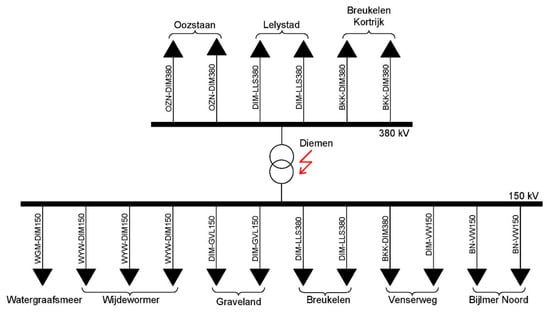
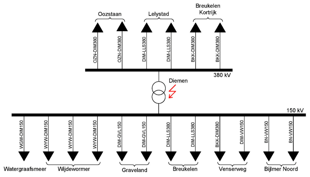
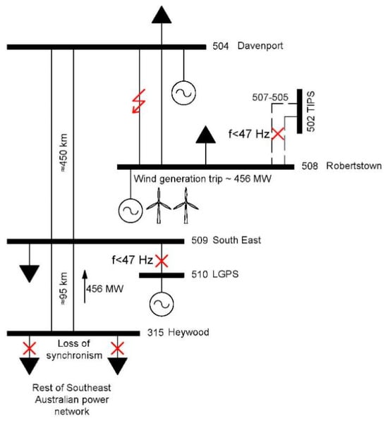
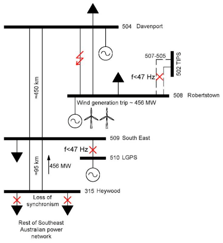
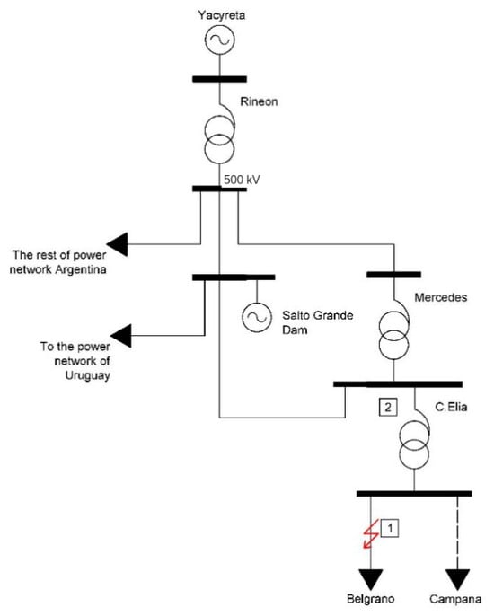
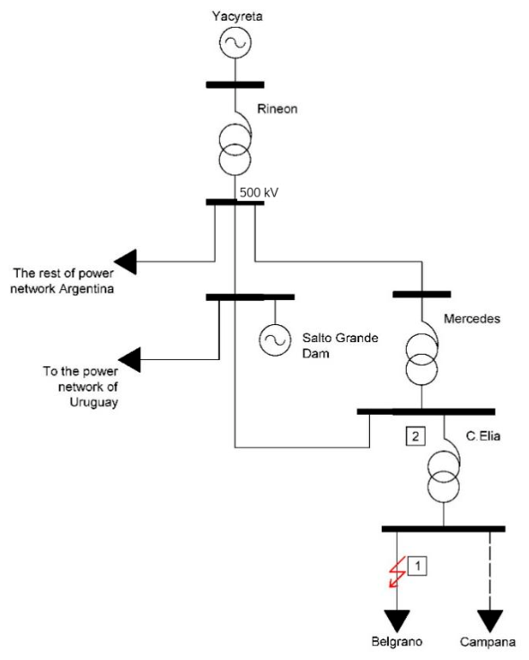
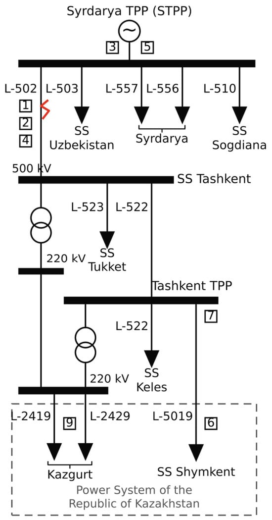
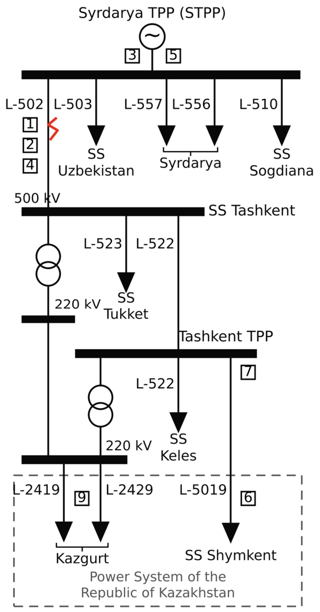
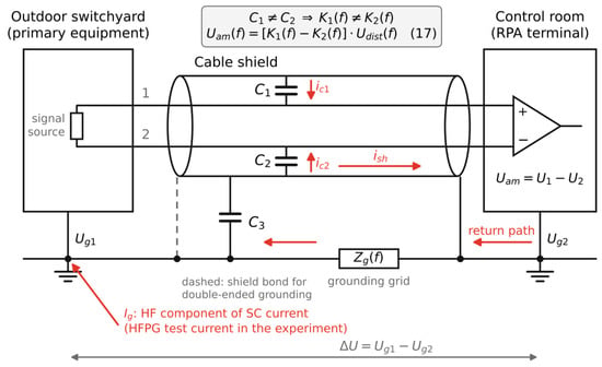
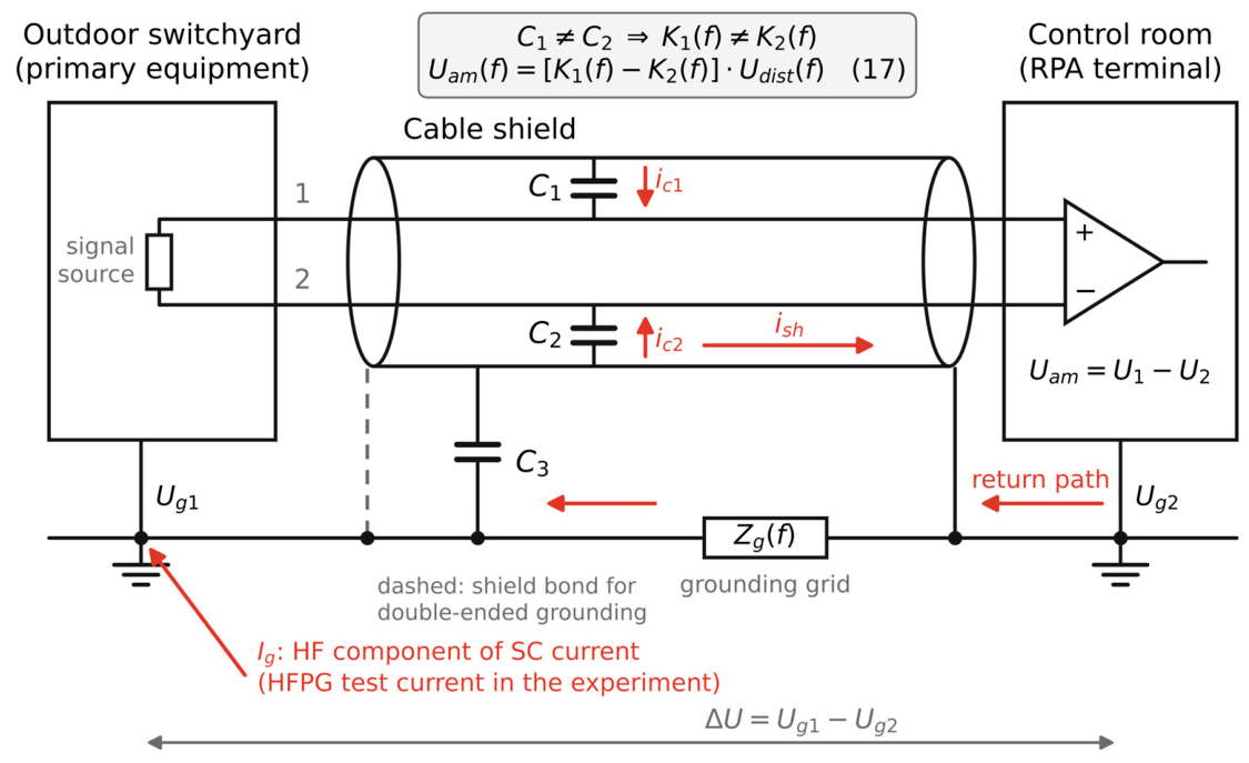
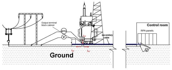
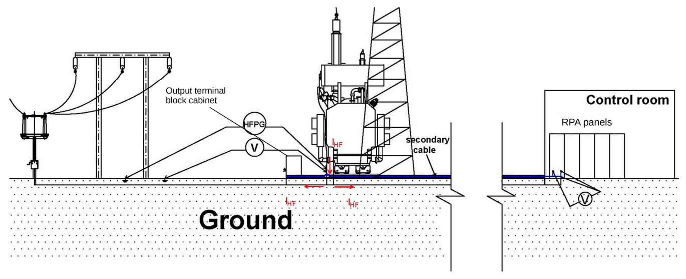
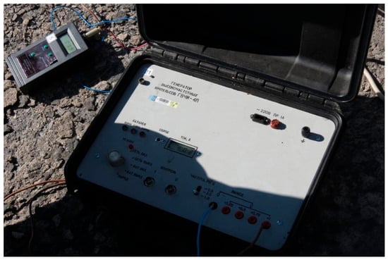
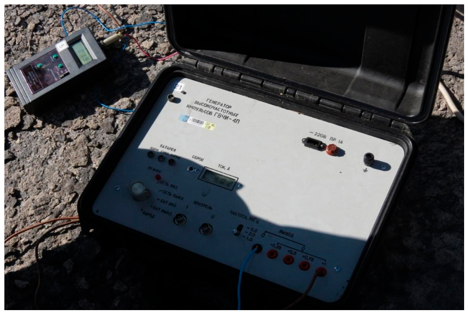
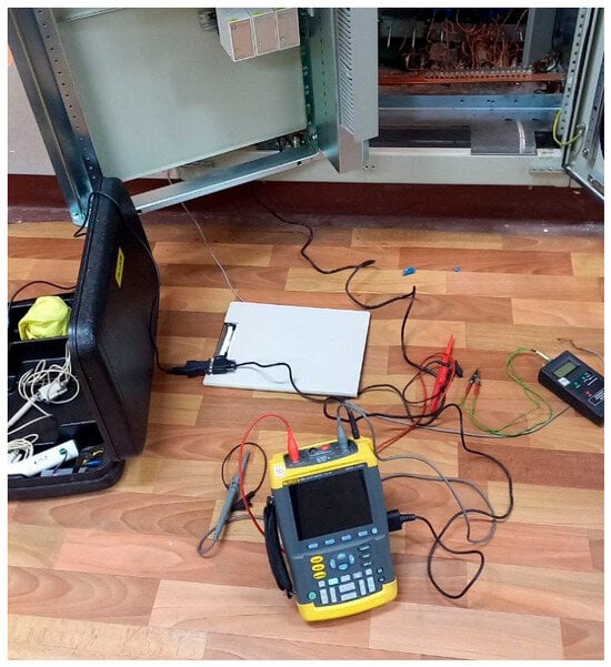
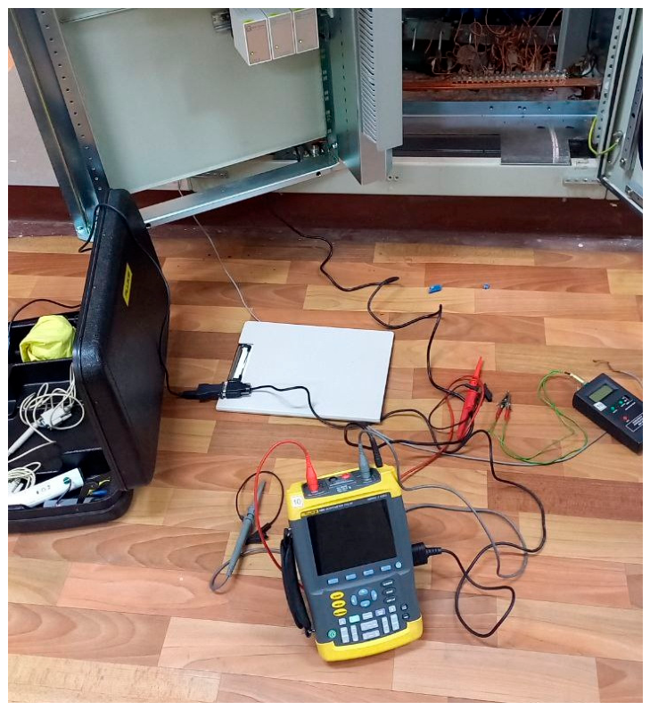
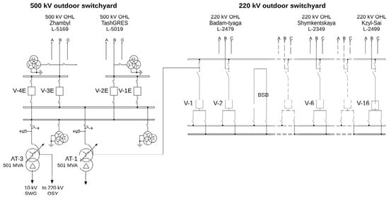
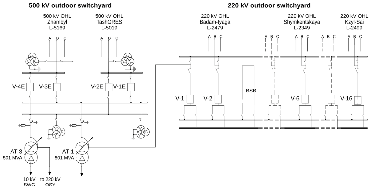
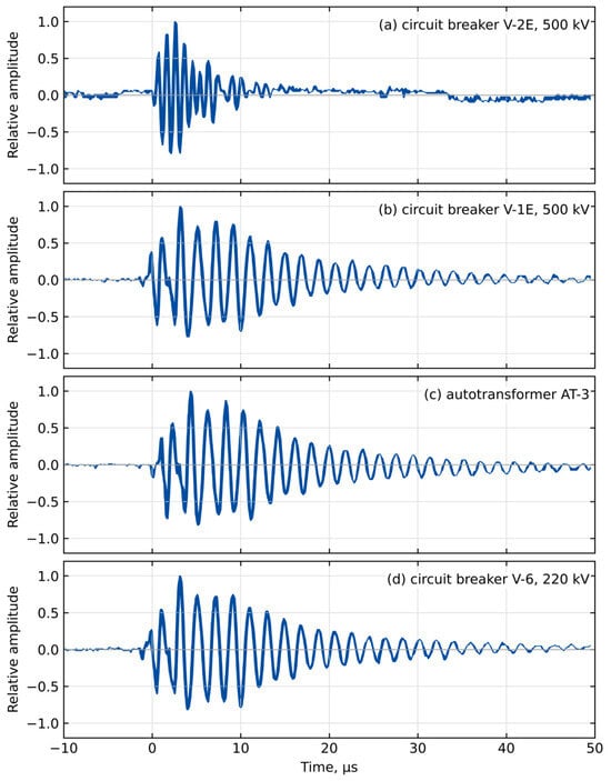
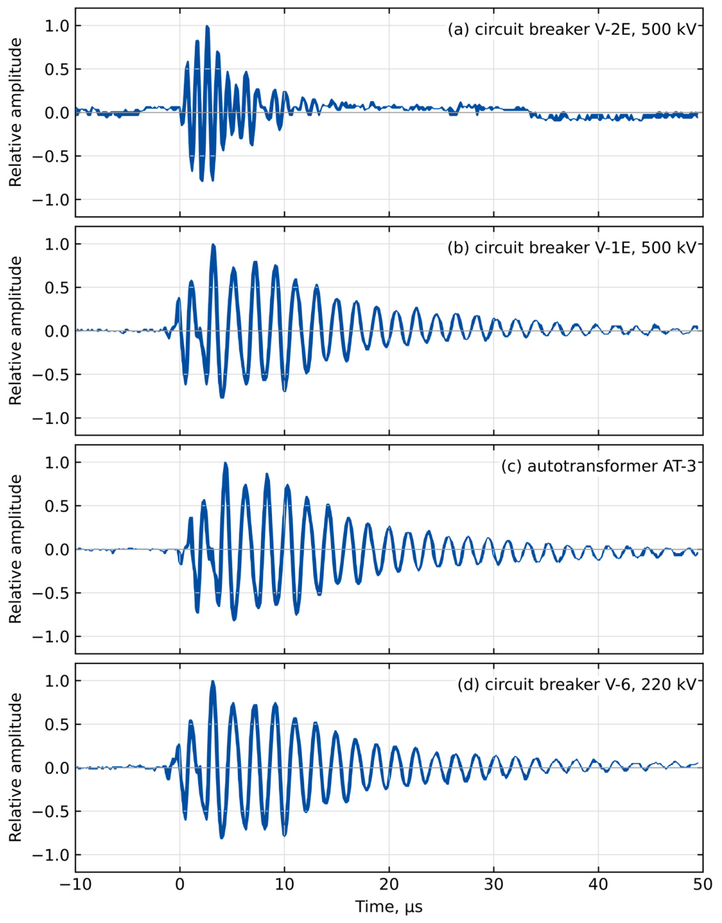
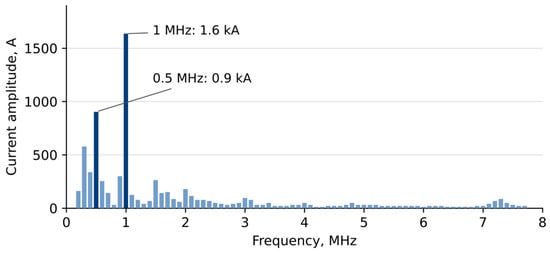
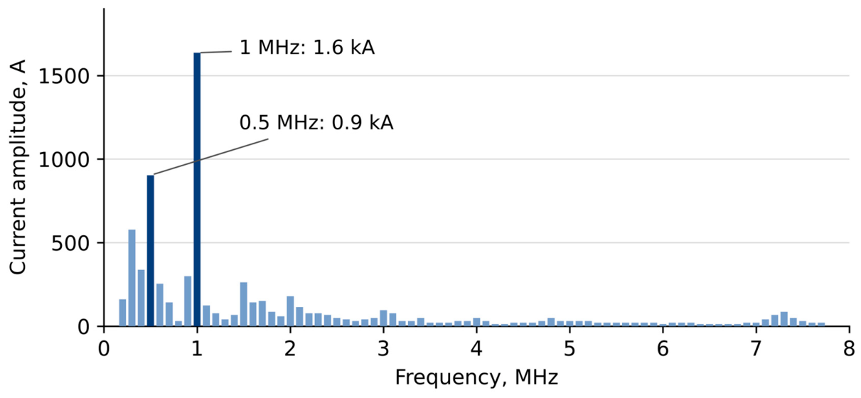

Disclaimer/Publisher’s Note: The statements, opinions and data contained in all publications are solely those of the individual author(s) and contributor(s) and not of MDPI and/or the editor(s). MDPI and/or the editor(s) disclaim responsibility for any injury to people or property resulting from any ideas, methods, instructions or products referred to in the content. |
© 2026 by the authors. Licensee MDPI, Basel, Switzerland. This article is an open access article distributed under the terms and conditions of the Creative Commons Attribution (CC BY) license.