


Abstract
This paper presents the design, hardware-in-the-loop (HiL) implementation and experimental validation of a closed-loop thermal management system (TMS) that employs a Texas Instruments C2000 LAUNCHXL-F28379D microcontroller integrated with MATLAB/Simulink real-time controller development. The developed TMS consists of a radiator with fixed fan cooling, a DC pump actuated through a pulse-width modulation (PWM) signal, a Hall-effect-based flow sensor, a heatsink temperature sensor and two negative temperature coefficient (NTC) water temperature sensors to measure the inlet and outlet coolant temperatures on either side of the heatsink. In order to make the sensor outputs compatible with the analog-to-digital converters (ADCs) of the microcontroller, a hardware scaling board is designed, while the PWM output of the microcontroller is utilized through a hardware interface to switch a 12 V DC PWM signal for the pump. For the flow control loop, open-loop experimental measurements are employed to derive a third-order state-space mathematical model of the TMS, where a high coefficient of determination between the real-time system and the mathematical model demonstrates the acceptable accuracy of the developed model. The identified third-order model is reduced to a second-order representation by removing a near-canceling pole–zero pair, while accounting for input delay, flow offset and pump duty cycle scaling. For the closed-loop heatsink temperature control, a practical control framework is adjusted iteratively since the ambient temperature influence and thermal disturbances make the extraction of a sufficiently reliable mathematical model less practical for controller tuning. The experimental results verify stable heatsink temperature regulation with low steady-state error, although with slower dynamics as expected due to the thermal inertia of the system. In this work, the developed HiL-based TMS provides a practical platform for the implementation and validation of real-time thermal control strategies.
1. Introduction
The increasing adoption of electric vehicles (EVs) has increased the demand for high-efficiency, compact and reliable power conversion systems in modern transportation infrastructures [1,2]. EVs are not only considered an important solution for reducing transport-related emissions, but also a complex system in which the electrical, thermal, mechanical and control subsystems are closely interconnected [3,4]. Therefore, the performance of the propulsion system, charging unit, battery pack and auxiliary power interfaces depends on the efficiency and reliable operation of the employed power electronic converters [5,6,7]. Recent developments in EV charging systems have focused on converter topologies, semiconductor technologies, charging standards and practical implementation methods to improve efficiency, power density and flexibility under different operating conditions [7,8,9]. At the same time, thermal management is an important consideration in EV systems, since unsuitable thermal operating conditions can reduce the performance and lifetime of the battery, electrical machine and power electronic converters [10,11,12].
Power electronic converters provide the electrical interface between the battery, electrical machine, grid, auxiliary loads and charging system [13,14]. The traction inverter is used for DC/AC conversion between the battery and electrical machine, while DC/DC converters and EV chargers are used to regulate voltage levels and control energy transfer under different operating conditions [15,16]. For high-power charging applications, different converter structures such as power-electronic-transformer-based architectures [17] and multiport isolated converters have also been investigated to improve efficiency, electrical isolation, power density and control flexibility [18,19,20]. However, the wide operating voltage range, dynamic load conditions and compact design of EV converters make both electrical and thermal design more challenging [21]. Therefore, improving only the electrical efficiency of a converter is not sufficient. The thermal behavior of a converter should also be considered to maintain stable and reliable operation [22,23].
The development of semiconductor technologies has enabled power electronic converters to operate at higher switching frequencies with higher efficiency and power densities [22,24,25]. In particular, SiC- and GaN-based semiconductor devices have provided new possibilities for compact traction inverters and charging converters, where efficiency, weight, volume and dynamic response are important design parameters [15,26]. However, increasing the switching capability and reducing the converter size also increase the concentration of heat inside a converter. This becomes more important in high-power EV applications, where the generated losses should be removed through a limited cooling area while a converter operates under different loading and ambient conditions [27,28]. Thus, the thermal design of a converter cannot be considered independently from the electrical design and control system. Previous studies on SiC power modules and wide-bandgap semiconductor devices have shown that thermal resistance, heat spreading, packaging structure and local heat generation have an important influence on the thermal performance of a converter [24,29]. An effective thermal management system is therefore required to keep the converter temperature within the allowable operating range and support reliable operation under practical operating conditions.
Thermal management has a direct influence on both the reliability and power density of automotive power electronic converters. The main heat generation in traction converters occurs in the semiconductor switches, while other components such as busbars, capacitors, interconnections and packaging layers can also contribute to thermal stress. Different cooling methods have been developed for traction applications, including indirect cold-plate cooling, direct cooling and double-sided module cooling [12,22,30]. The selected cooling method can affect thermal resistance, converter volume and packaging structure. At the same time, a converter is expected to become more compact while the required heat dissipation capability is increasing. From a reliability point of view, the lifetime of power electronic converters is strongly affected by thermal and electrical stresses, where temperature is considered one of the main factors influencing the failure of semiconductor devices and passive components [31]. Therefore, a thermal management system should not only remove generated heat, but should also maintain a stable thermal operating condition and reduce large temperature variations during different operating conditions.
Different thermal management methods have been investigated for EV and power electronic applications. These methods include conventional forced-air and liquid cooling, as well as more advanced methods such as phase-change-material-assisted cooling, immersion cooling, jet or spray cooling and integrated cooling channels. In general, the thermal management problem can be considered from two sides. The first is reducing heat generation by controlling the converter operating condition, while the second is improving heat removal through the cooling hardware and its active control [32]. In EV applications, integrated thermal management systems have also been investigated, where the thermal loops of the battery, electrical machine, cabin and power electronic converters are coordinated to improve overall system performance [10,33,34]. Furthermore, device- and package-level cooling methods have been developed to improve heat spreading, reduce thermal resistance and increase heat extraction from wide-bandgap semiconductor devices [24]. Therefore, the thermal behavior of a converter depends on several parts of the system, including the semiconductor devices, packaging structure, cooling hardware, converter operating conditions and control system.
In addition to cooling hardware, thermal modeling and system identification are important for analyzing and controlling the thermal behavior of power electronic converters. Fast heatsink-based thermal models have been proposed to represent airflow and temperature variations without using detailed CFD-based models [35]. Online identification methods have also been investigated to estimate the heat dissipation condition of forced-air-cooled power converters and support condition-based operation [36]. These methods provide useful tools for thermal modeling and thermal state estimation. However, many of the available studies mainly focus on thermal design, numerical modeling or state estimation. Comparatively fewer studies consider the complete implementation of a closed-loop thermal management system, including sensor interfacing, analog-to-digital converter compatibility, actuator limitations, pump controllability, embedded controller implementation and experimental validation of the complete thermal control loop.
Hardware-in-the-loop (HiL) and power hardware-in-the-loop (PHiL) methods can be used to reduce the gap between simulation and experimental implementation. These methods combine real-time calculation with actual hardware interfaces and make it possible to investigate controller operation, input and output behavior, time-step limitations and implementation challenges before complete integration into the final system [37]. In power electronic applications, an embedded control platform is an important part of the system, since the control and monitoring functions require sufficient computational capability, reliable signal measurement and suitable switching interfaces [38,39]. Low-cost real-time platforms based on a Texas Instruments TMS320F28379D have previously been investigated as an alternative between commercial rapid-control-prototyping platforms and conventional low-cost controllers [40]. These platforms can provide analog measurement, PWM generation and real-time control capability. However, when such embedded platforms are used for thermal management, additional practical challenges should be considered. These include nonlinear sensor characteristics, voltage scaling, PWM-controlled pump behavior, flow sensor resolution, actuator dead zones and variations in the ambient temperature.
Based on these considerations, this paper presents the design, HiL implementation and experimental validation of a closed-loop thermal management system for high-power EV converter applications. The proposed system is implemented using a Texas Instruments C2000 LAUNCHXL-F28379D microcontroller together with MATLAB/Simulink for real-time implementation. The experimental thermal management system consists of a radiator with fixed fan cooling, a DC pump controlled by PWM, a Hall-effect-based flow sensor, a heatsink temperature sensor and two negative temperature coefficient (NTC) sensors for measuring the inlet and outlet coolant temperatures. A dedicated hardware interface is developed to scale the sensor output voltages to the ADC operating range of the microcontroller and to provide the required PWM signal for controlling the pump. Open-loop tests are carried out to investigate the operating range and controllability of the pump. Based on the obtained experimental results, a third-order state-space model is developed for the flow control loop. The obtained model is then used to tune the PI controller. For the heatsink temperature control loop, the controller is adjusted iteratively since the thermal response is directly affected by the ambient temperature. Then, the closed-loop thermal management system is experimentally tested considering the practical limitations of the pump, sensor characteristics, hardware interface and thermal operating conditions. The main contributions of this paper are summarized as follows:
A low-cost embedded HiL-based TMS platform is developed for high-power EV converter thermal control applications using a C2000 microcontroller and MATLAB/Simulink real-time implementation. A complete hardware interfacing structure is designed for NTC-based temperature sensing, flow measurement, ADC-compatible voltage scaling and PWM-based pump actuation. The flow control dynamics of the experimental TMS are identified through open-loop step testing, and a PI controller is tuned using the obtained third-order state-space model. A closed-loop heatsink temperature control strategy is experimentally implemented and validated, considering the practical limitations of the pump, sensor behavior and ambient-temperature influence.
The remainder of this paper is organized as follows: Section 2 presents the experimental TMS architecture, sensor-interfacing hardware and overall system design. Section 3 describes the HiL control framework, open-loop system identification and PI controller design. Section 4 investigates the HiL implementation and experimental results of the flow/heatsink temperature control loops. Section 5 concludes the paper and summarizes the main findings and future work.
2. System Design and Method
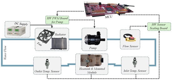
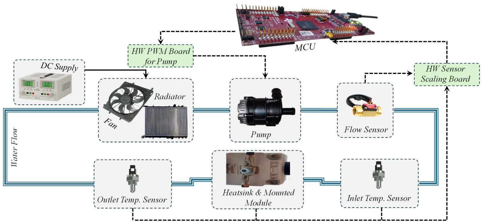
The architecture of the designed thermal management system (TMS) is shown in Figure 1. The blue line indicates the coolant flow path through the experimental TMS. The experimental TMS consists of a radiator with a fixed 12 V DC fan, a 12 V DC pump, a flow sensor, a heatsink temperature sensor, and two coolant temperature sensors placed at the inlet and outlet of the heatsink. The voltage signals from the temperature sensors are scaled through a hardware interface to obtain a suitable voltage range for the analog-to-digital converters (ADCs) of the microcontroller unit (MCU).
Figure 1.
Schematic diagram of the developed TMS including the 12 V DC pump and radiator fan, coolant flow sensor and heatsink and inlet/outlet NTC temperature sensors (0–100 °C). The hardware interfaces provide ADC-compatible sensor signals and a 12 V PWM signal for pump control.
The PWM signal from the MCU is utilized through the hardware interface to generate the required 12 V PWM signal for controlling the pump unit. The microcontroller is a Texas Instruments LAUNCHXL-F28379D. This microcontroller can be programmed in MATLAB/Simulink using the C2000 library. It also allows the main system variables to be monitored in real-time during the experimental tests. The selected MCU is employed for the real-time implementation of the developed control algorithms, while MATLAB/Simulink is used for controller development and monitoring of the experimental system. In the developed platform, the physical TMS provides the measured feedback signals and the MCU generates the corresponding PWM command for controlling the pump. The coolant flow sensor uses Hall effect elements to measure the water flow and provides a digital output signal. The heatsink and coolant temperature sensors are negative temperature coefficient (NTC) sensors, where the sensor resistance decreases as the temperature increases. For each NTC sensor, a voltage divider is used on the hardware sensor scaling board. The resistance R2 can be calculated as:
where RNTC,Min [Ω] and RNTC,Max[Ω] are the minimum and maximum NTC resistance values corresponding to the required temperature measurement range of 0–100 °C. The corresponding resistance values are calculated based on the temperature-dependent characteristics of the NTC sensor as follows:
where β[K] is a material constant that describes how strongly the resistance changes with temperature and R25[Ω] is the nominal resistance at 25 °C or 298.15 K. The NTC temperature sensor and the calculated fixed resistance R2 are connected in series to form a voltage divider circuit. In the implemented configuration, the NTC resistance RT is connected between the supply voltage Vdd and the measurement node, while R2 is connected between the measurement node and ground. Therefore, the voltage VADC is measured across R2 and the corresponding NTC resistance can be calculated as:
where VADC [V] represents the measured voltage across the fixed resistance R2 and Vdd [V] denotes the supply voltage applied to the voltage divider circuit. Based on the calculated NTC resistance, the corresponding temperature can be obtained using the resistance–temperature characteristics of the sensor. In order to calculate the temperature in Kelvins from the NTC resistance RT the following equation can be used:
where T[K] represents the temperature calculated from the measured NTC resistance. In order to convert the calculated temperature from Kelvin to degrees Celsius, the following equation is employed:
T[°C] = T[K] − 273.15
3. Hardware-in-the-Loop (HiL) Control Framework Design
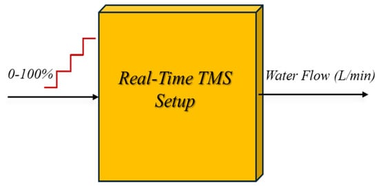
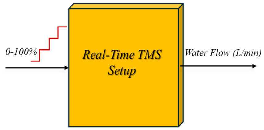
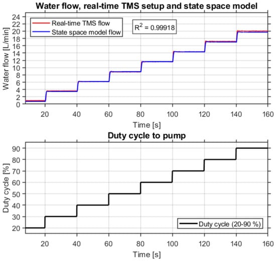
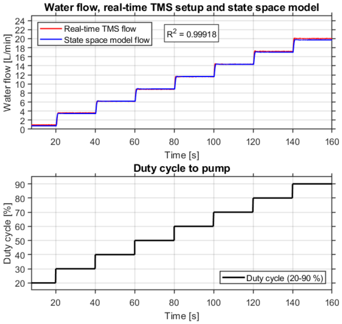
A MATLAB-based PID Tuner is used to determine the control parameters of the developed proportional–integral (PI) controller for the coolant flow loop. Since the pump PWM command and the corresponding flow sensor response are available from the experimental setup, the dynamic behavior of the system can first be investigated through open-loop measurements. The relation between the pump PWM duty cycle and the measured coolant flow is used to develop a mathematical model of the flow control system. The obtained model is then used to calculate the parameters of the PI controller and improve the closed-loop response. The MATLAB PID Tuner uses the linearized model of the plant between the controller output, which is the pump PWM command, and the measured flow signal. Based on this model, the parameters of the controller are calculated by selecting an appropriate gain crossover frequency and phase margin. Therefore, the controller tuning is based on the dynamic behavior obtained from the experimental TMS rather than only on iterative adjustment. Figure 2 shows the applied duty cycle step change and the corresponding open-loop response of the flow sensor. The open-loop measurements are used to investigate both the dynamic response and practical controllability range of the pump.
Figure 2.
Illustration of the applied duty cycle step change and the open-loop flow sensor response.
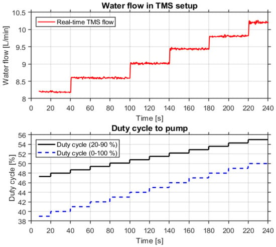
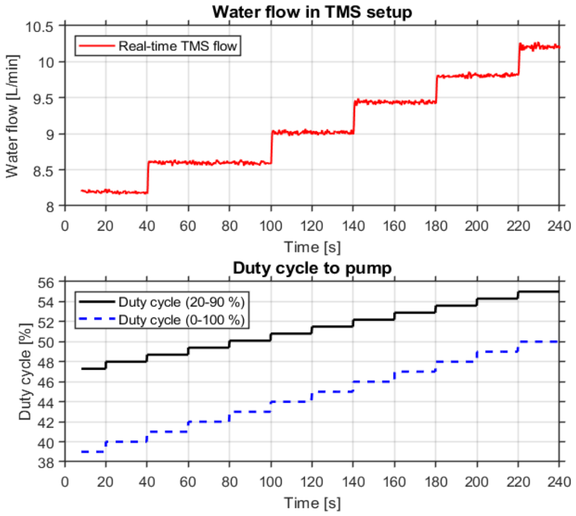
The obtained results show that the useful operating range of the pump is approximately between 20% and 90% duty cycle. Below and above this range, the pump response becomes difficult to regulate. Furthermore, the open-loop test shown in Figure 3 indicates that a 1% increase in the scaled duty cycle signal does not always result in an observable variation in the pump speed or measured coolant flow. In several operating points, the duty cycle has to be increased by approximately 3% before a measurable change in the pump speed and flow sensor response can be observed. This behavior shows that the pump has a limited effective resolution and introduces a nonlinear characteristic into the flow control loop. Therefore, these practical limitations should be considered during the modeling and controller-tuning process, as they can influence the closed-loop response. The flow response to the duty cycle indicates an effective low-duty dead zone, high-duty saturation and limited resolution within the controllable region. Therefore, the control implementation restricts the commanded duty cycle to approximately 20–90%. The nonlinear pump behavior is acknowledged as an experimental limitation; explicit nonlinear dead zone compensation and anti-windup validation are not demonstrated in the present experiments.
Figure 3.
Open-loop coolant flow response to consecutive 1% duty cycle increases (scaled from 0% to 100%).
Based on the measured open-loop step response, a third-order state-space model of the coolant flow control loop is identified using an iterative prediction error minimization approach. In this method, the state-space parameters are estimated by minimizing the prediction error between the measured coolant flow response and the corresponding model output. The prediction error minimization principle can be expressed as:
where β is the estimated model parameters, μ(k) is the measured coolant flow and is the model’s one-step-ahead predicted output. The PWM duty cycle command is considered the system input, while the measured coolant flow response is employed as the output. The identified mathematical model is expressed as:
where x(t) denotes the state vector, u(t) is the input signal, y(t) presents the output signal and is the time derivative of the state vector. Moreover, A, B, C and D are the state-space matrices of the designed open-loop TMS, which are calculated as follows:
This model is presented with sufficient numerical precision to preserve its pole–zero characteristics. Further investigation of the third-order representation indicates the presence of a nearly canceling pole–zero pair close to the origin. The numerical values of the corresponding pole and zero are approximately 4.58 × 10⁻¹⁰ and 1.25 × 10⁻¹⁰. Although these values are extremely small, rounding the individual state-space matrices to four decimal places introduces numerical deviations in the pole–zero locations. In particular, the rounded model contains a positive pole of approximately 2.46 × 10⁻⁵, which affects the calculated stability characteristics and does not adequately represent the original identified dynamics. Therefore, the full-precision matrices are retained to avoid numerical inconsistencies associated with the rounded representation.
Considering the near cancellation of the additional pole–zero pair, a model-order reduction is performed to obtain a second-order representation of the experimental coolant flow dynamics. The objective of this reduction is to remove the near-canceling mode while preserving the dominant input–output characteristics required for the controller design procedure. The transfer function representation of the identified third-order state-space model is expressed as:
where I is the identity matrix and s is the Laplace variable. Based on the identified pole–zero characteristics, the corresponding transfer function can be represented by:
where p0 and z0 are the nearly canceling pole and zero close to the origin, while p1, p2 and z1 are the remaining poles and zeros of the identified system. Since the contribution of the near-canceling pole–zero pair is negligible over the investigated experimental time scale, the corresponding mode is removed to obtain a reduced second-order representation:
G(s) = C(sI − A)−1B + D
Note that in order to fine-tune the mathematical model and take any nonlinearity into consideration, an additional offset and delay are added to the model. The corresponding reduced-order state-space representation is expressed as:
where the second-order state-space matrices are given as:
Based on the obtained matrices, the corresponding reduced-order transfer function is calculated as:
It should be noted that the model-order reduction is approximate and does not result in an identical representation of the original third-order model at all frequencies. However, considering the nearly canceling pole–zero pair, the reduced-order model retains the dominant input–output characteristics of the identified system over the investigated operating conditions. Therefore, the second-order representation is employed for the subsequent controller design procedure, while the original third-order model is retained to describe the system identification results. The resulting model is expressed as:
where the input delay is 0.18 s and the constant output offset is −4.723 L/min. A comparison of the open-loop step response of the real-time system and the mathematical model is summarized in Figure 4. This figure shows a coefficient of determination (R2) value of 0.99918, which demonstrates the acceptable accuracy of the TMS.
Figure 4.
Step response comparison between the real-time and mathematical model of TMS.
Based on the obtained reduced-order mathematical model of the TMS, the PI controller is tuned using a mathematical approach by selecting a suitable gain crossover frequency and phase margin. Since the experimental pump operates within an effective duty cycle range of approximately 20–90%, the output of the PI controller is scaled from 0–100% to the corresponding physical pump operating range. The relationship between the PI controller output and the pump duty cycle is expressed as:
where uPI(t) represents the controller output in percent within the range of 0–100%, and u(t) is the corresponding physical pump duty cycle. Considering the applied scaling and the identified input delay, the equivalent dynamic plant for the continuous-time controller analysis is represented as:
u(t) = 20 + 0.7uPI(t)
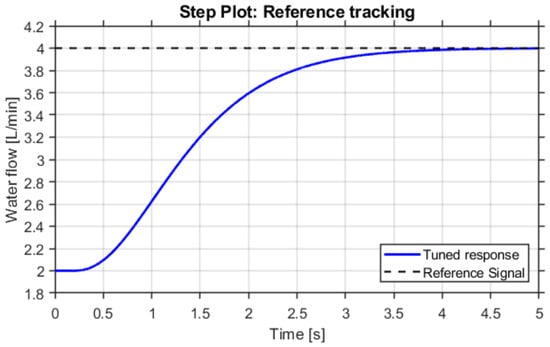
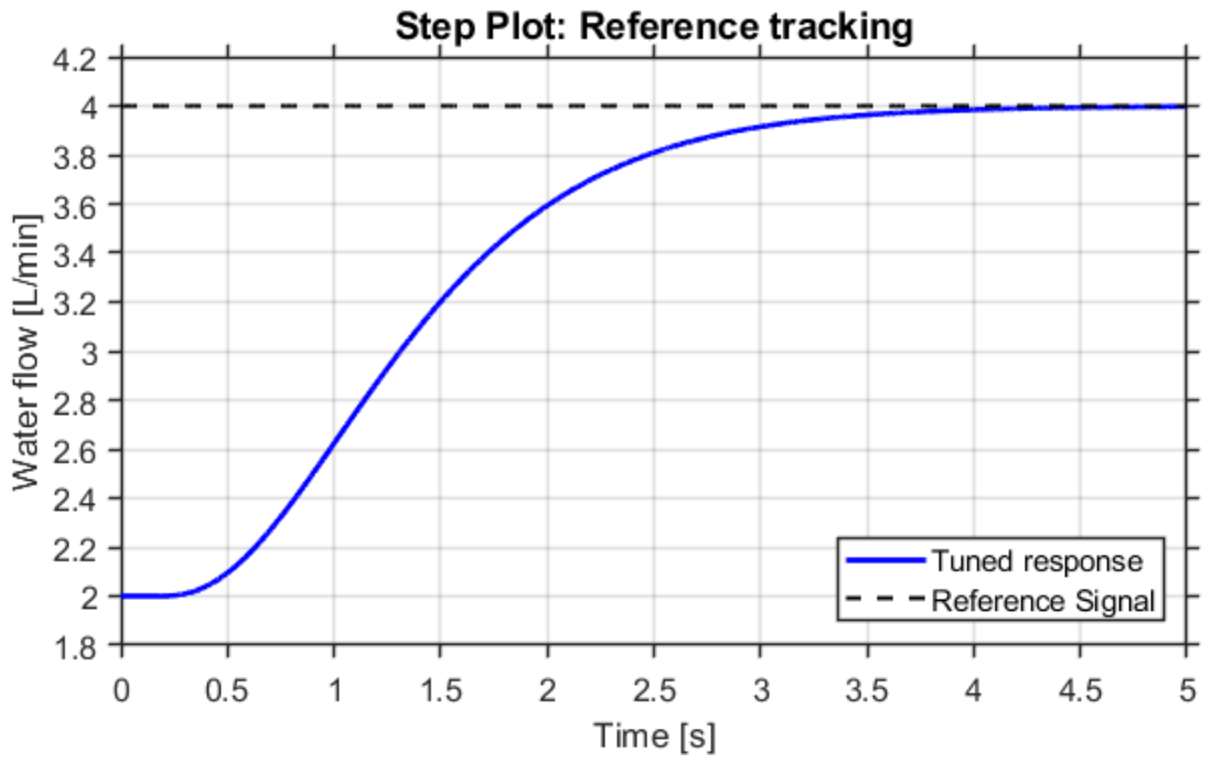
The proportional and integral gains obtained from the controller-tuning procedure are Kp = 0.1011647570292 and Ki = 3.58960191834397. These parameters are associated with the scaled plant model rather than the original unscaled state-space representation. The corresponding model-based closed-loop coolant flow response is presented in Figure 5, where the reference signal is changed from 2 to 4 L/min. In addition to the water-flow control loop the TMS includes a separate control loop for regulating the heatsink temperature. Unlike the water-flow control loop the heatsink-temperature control loop was tuned experimentally due to the thermal characteristics of the system. The reason for not making a mathematical model of the system to tune the PI controller is that such a model should include the heatsink temperature. This heatsink temperature is always influenced by the ambient temperature in the testing environment, which is usually assumed to be constant and not measured by the microcontroller. Such a mathematical model becomes unusable as soon as the ambient temperature changes. It is therefore most time-efficient to tune the PI controller of the closed-loop heatsink temperature control iteratively. This approach was selected because the experimental setup did not measure ambient temperature, which influences its thermal operating point. A disturbance-aware thermal model and systematic retuning are identified as future work.
Figure 5.
Model-based closed-loop flow-reference tracking response for a step from 2 to 4 L/min, considering the 0.7 duty cycle scaling of the controller and 0.18 s model input delay.
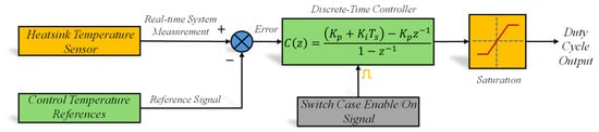
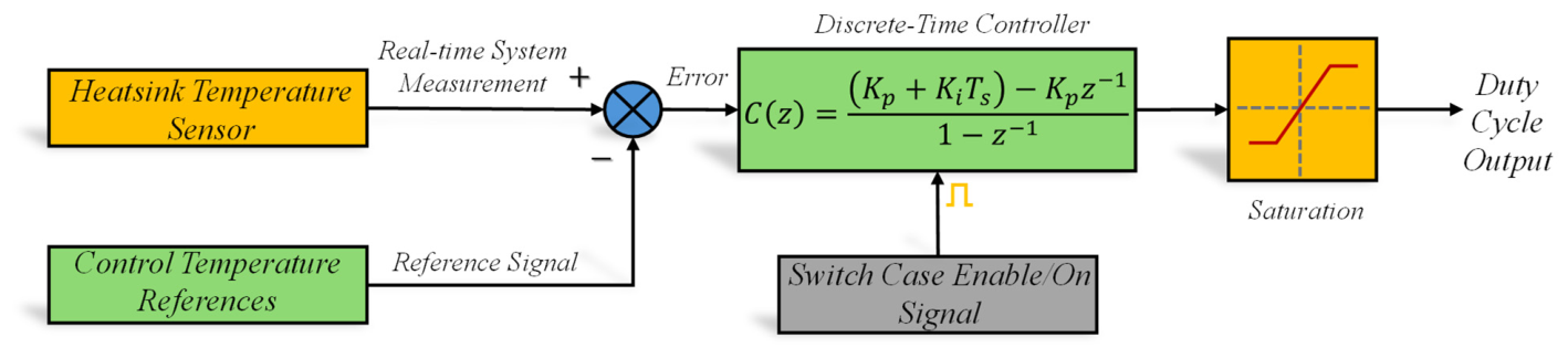
Due to the nature of the designed TMS, where an increase in the duty cycle leads to a decrease in temperature, the calculation of the error signal going into the closed-loop controller is reversed, which means that the heatsink temperature reference is subtracted from the measured heatsink temperature. The architecture of the controller is presented in Figure 6.
Figure 6.
Closed-loop heatsink temperature control architecture implemented in the HiL platform.
4. HiL Implementation and Experimental TMS Results
The developed HiL-based experimental platform integrates a Texas Instruments C2000 LAUNCHXL-F28379D microcontroller with MATLAB/Simulink for controller development, implementation and real-time monitoring. In the developed configuration, the radiator, pump, heatsink and corresponding temperature and flow sensors are implemented as physical hardware, while the C2000 microcontroller executes the developed control algorithms and generates the required PWM signals. The mathematical model presented in Section 3 is employed for system identification and controller tuning, while the physical TMS is used for experimental evaluation of closed-loop control performance. This configuration enables investigation of the real-time implementation and practical operating characteristics of the developed thermal control strategies.
From a hardware perspective, the selected LAUNCHXL-F28379D C2000 MCU offers two 32-bit C28x floating-point CPU cores running at up to 200 MHz each, supported by two control law accelerator (CLA) coprocessors, which are appropriate for executing the control loops in real-time while maintaining sufficient resources for monitoring and diagnostics. The device also integrates up to 1 MB of on-chip flash and up to 204 KB of SRAM for real-time implementation and data buffering, together with four independent 16-bit ADCs that allow simultaneous acquisition of different analog channels, such as NTC-based temperature dividers and other sensor signals. The enhanced PWM (ePWM) peripherals, which include HRPWM-capable outputs, furnish deterministic and fine duty cycle generation for the pump drive, while the integrated protection and connectivity features facilitate a robust and well-instrumented HiL workflow. This diagnostic resulted in the discovery of an inaccurate pump, as described in the previous section, that needs to be substituted to obtain a better duty cycle, bandwidth and accuracy.
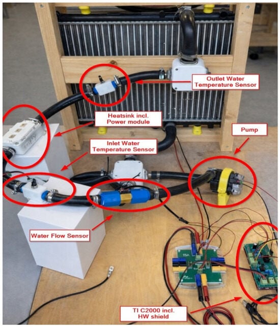
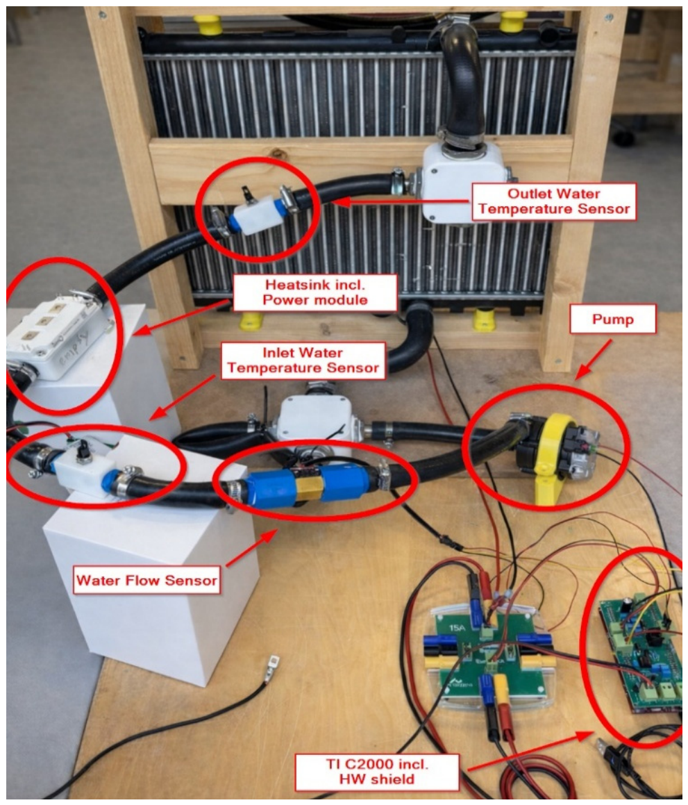
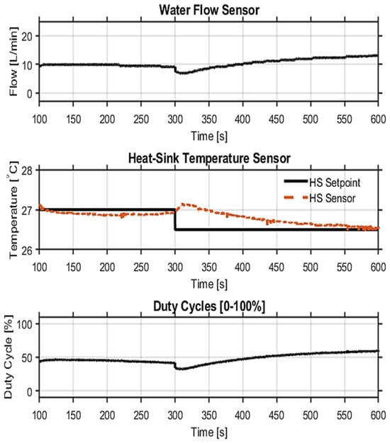
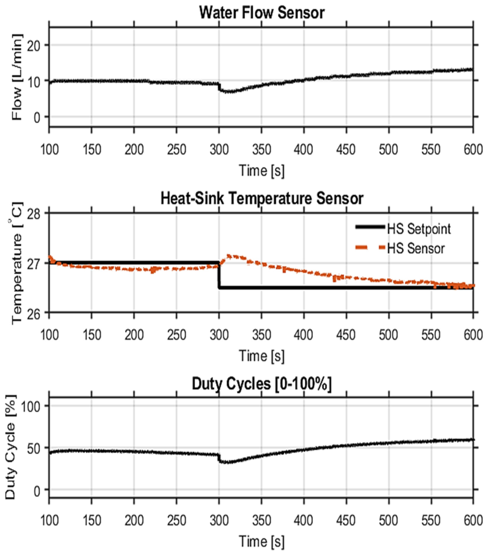
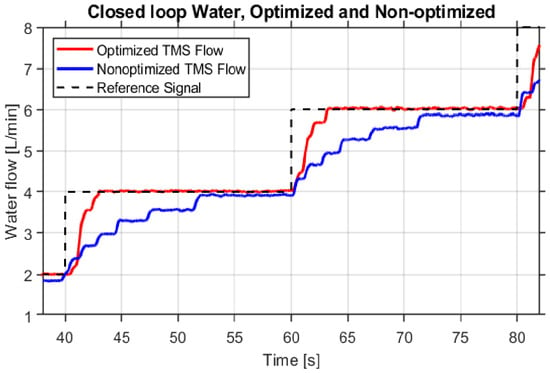
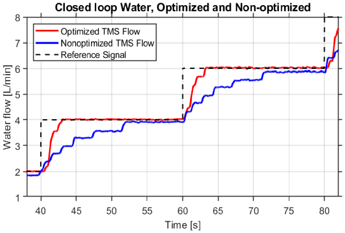
Figure 7 shows the TMS experimental setup with the C2000 microcontroller and software interface, which operates as a hardware-in-the-loop platform. Figure 8 shows the heatsink temperature control response with the tuned controller, which regulates the temperature from 27 °C to 26.5 °C over a period of 300 s. The proportional and integral gains for the designed controller are set to Kp = −15 and Ki = 0.25, respectively. The error between the heatsink temperature setpoint and the heatsink temperature sensor before t = 300 s is measured to be around 0.1 °C going towards 0, which is acceptable in large heat capacitance systems such as the TMS. Utilizing the optimized pump controller from Section III on the real-time system and comparing it with the nonoptimized controller demonstrate the clear difference in the results. It should be noted that the experimental validation of the heatsink temperature controller is limited to a reference change of 0.5 °C under the investigated operating conditions. Therefore, further investigations considering larger temperature variations, different thermal loads and ambient-temperature conditions are required to evaluate the control performance over a wider operating range.
Figure 7.
Experimental TMS setup implementing a HiL platform using a LAUNCHXL-F28379D C2000 microcontroller and MATLAB monitoring interface with physical radiator, pump, flow and temperature sensors.
Figure 8.
Closed-loop heatsink temperature control response for a temperature step from 27 °C to 26.5 °C.
From Figure 9, it can be seen that the step responses of the nonoptimized and optimized controllers are compared and the optimized controller reaches the reference setpoint at around 2.5 s, whereas the nonoptimized takes around 12 s. The closed-loop temperature control in Figure 8 is considerably slower compared to the closed-loop flow control. The reason for this is that it takes time to extract the heat energy through the use of increased water flow. As in the case of Figure 8, the water flow is slowly increased and the integrator is gradually ramped up, in order to keep the system stable. The temperature control performance could be further improved by measuring the ambient temperature and using this information to develop a mathematical model of the thermal plant. Adjusting and fine-tuning the control iteratively could result in a long process if every simulation takes around 10 min, as shown in Figure 8. Although the developed experimental TMS includes temperature sensors at the inlet and outlet of the heatsink, synchronized measurements of the coolant temperature difference were not recorded during the experimental tests. Therefore, a quantitative assessment of the extracted thermal power based on the coolant mass flow rate and temperature difference could not be performed using the available experimental data. Further investigations will include synchronized temperature and flow measurements, together with the corresponding electrical heating input, to evaluate the thermal energy balance and heat extraction performance of the developed system.
Figure 9.
Comparison of the step responses for the nonoptimized and optimized controllers.
5. Conclusions
This paper suggested the design, implementation and experimental validation of a closed-loop TMS using a Texas Instruments C2000 LAUNCHXL-F28379D microcontroller integrated with MATLAB/Simulink HiL operation. The developed setup combines a radiator with fixed fan cooling, a DC pump actuated via PWM, a flow sensor and multiple NTC temperature sensors measuring heatsink and coolant temperatures. Sensor interfacing is realized through hardware voltage scaling to match the ADC operating range. For the NTC temperature sensors, the series resistance of the voltage-divider circuit is selected based on the required temperature measurement range, allowing the corresponding sensor voltage to be measured by the MCU ADC. Two PI-based control strategies are implemented and investigated. For flow control, open-loop step tests enabled system identification of a third-order state-space model with a high R-squared value between measured and modeled dynamics. A PI controller was subsequently tuned using a target gain crossover frequency and deployed on the TMS setup. Experimental results show a clear improvement in reference tracking performance compared to a nonoptimized controller reduces the settling time from approximately 12 s to 2.5 s. For heatsink temperature regulation, controller tuning is performed iteratively because of the significant influence of ambient temperature and thermal disturbances. The final temperature controller achieved stable regulation with low steady-state error, although with slower dynamics, as expected from the system thermal inertia. This paper also emphasized practical limitations in the actuator hardware. The pump exhibited nonlinear behavior, including loss of controllability below 20% and above 90% duty cycle and limited effective resolution, where multiple duty cycle increments are needed before measurable flow changes happen. Future work will focus on replacing the pump with a unit that improves linearity and duty cycle resolution to expand the controllable operating range. Further, adding ambient temperature sensing would enable development of a more robust thermal model. In addition, the results establish a practical embedded-control testing platform, while systematic thermal energy balance validation and testing over wider operating conditions remain future work.
Author Contributions
Conceptualization, A.F.; methodology, J.S.J. and A.F.; software, J.S.J.; validation, J.S.J. and A.F.; formal analysis, J.S.J. and A.F.; investigation, J.S.J.; resources, A.F.; data curation, J.S.J.; writing—original draft preparation, J.S.J. and A.F.; writing—review and editing, J.S.J. and A.F.; visualization, J.S.J.; supervision, A.F.; project administration, A.F.; funding acquisition, A.F. All authors have read and agreed to the published version of the manuscript.
Funding
This research received no external funding.
Institutional Review Board Statement
Not applicable.
Informed Consent Statement
Not applicable.
Data Availability Statement
The data presented in this study are available on request from the corresponding author.
Acknowledgments
This work was supported by the European Union’s Horizon Europe research and innovation programme (grant agreement number: 101056896), project RHODaS. The views and opinions expressed herein are, however, those of the authors only and do not necessarily reflect those of the European Union or CINEA. Neither the European Union nor the granting authority can be held responsible for them.
Conflicts of Interest
The authors declare no conflict of interest.
References
- Liu, C.; Zhou, M.; Chen, X.; Zhuang, Y.; Cheng, X.; Li, Z.; Zhang, Y. A Modular and Scalable Multichannel Topology for Power-Class Interoperability in EV WPT System. IEEE Trans. Ind. Electron. 2026, 1–6. [Google Scholar] [CrossRef] [Scilit]
- Fathollahi, A.; Gheisarnejad, M.; Boudjadar, J.; Homayounzadeh, M.; Khooban, M.-H. Optimal Design of Wireless Charging Electric Buses-Based Machine Learning: A Case Study of Nguyen-Dupuis Network. IEEE Trans. Veh. Technol. 2023, 72, 8449–8458. [Google Scholar] [CrossRef] [Scilit]
- Kwon, D.; Son, S.; Park, K.; Das, A.K.; Park, Y. Design of Blockchain-Based Multi-Domain Authentication Protocol for Secure EV Charging Services in V2G Environments. IEEE Trans. Intell. Transp. Syst. 2024, 25, 21783–21795. [Google Scholar] [CrossRef] [Scilit]
- Gheisarnejad, M.; Fathollahi, A.; Sharifzadeh, M.; Laurendeau, E.; Andresen, B.; Al-Haddad, K. Optimal Policy Gradient-Based Type-2 Fuzzy Control for Multi-DC Terminal PEC Converter in 5G-Based Commercial Buildings. IEEE J. Emerg. Sel. Top. Power Electron. 2025, 13, 5149–5161. [Google Scholar] [CrossRef] [Scilit]
- Shi, Z.; Tang, Y.; Zhang, Y.; Guo, Y.; Sun, H.; Jiang, L. A Secondary-Side Semiactive 3-Phase Interleaved Resonant Converter Employing Multimode Modulation Scheme for Fast EV Charger Applications. IEEE Trans. Power Electron. 2022, 37, 13385–13397. [Google Scholar] [CrossRef] [Scilit]
- Kumar, S.; Srivastava, K.; Upadhyay, T. STC–DAB Converter Integrated Solar PV Off-Board Charger for Electric Vehicles With Power Quality Improvement. IEEE Trans. Aerosp. Electron. Syst. 2025, 61, 17500–17511. [Google Scholar] [CrossRef] [Scilit]
- Yavasoglu, H.A.; Shen, J.; Shi, C.; Gokasan, M.; Khaligh, A. Power Split Control Strategy for an EV Powertrain With Two Propulsion Machines. IEEE Trans. Transp. Electrif. 2015, 1, 382–390. [Google Scholar] [CrossRef] [Scilit]
- Ruttala, S.; Jayaram, N.; Kumar, B.; Naresh, S.V.K. A Comprehensive Review of EV Chargers: Topologies, Standards, Commercial Implementations, and Research Challenges. IEEE Access 2026, 14, 25623–25649. [Google Scholar] [CrossRef] [Scilit]
- Gheisarnejad, M.; Fathollahi, A.; Sharifzadeh, M.; Laurendeau, E.; Al-Haddad, K. Data-Driven Switching Control Technique Based on Deep Reinforcement Learning for Packed E-Cell as Smart EV Charger. IEEE Trans. Transp. Electrif. 2025, 11, 3194–3203. [Google Scholar] [CrossRef] [Scilit]
- Martin, G.E.; Baghdadi, M.E.; Hegazy, O. Advancements in Thermal Management for Electric Vehicles: Strategies, Architectures, and Power Electronics Cooling. IEEE Access 2025, 13, 147511–147544. [Google Scholar] [CrossRef] [Scilit]
- Kumar, R.R.; Bharatiraja, C.; Udhayakumar, K.; Devakirubakaran, S.; Sekar, K.S.; Mihet-Popa, L. Advances in Batteries, Battery Modeling, Battery Management System, Battery Thermal Management, SOC, SOH, and Charge/Discharge Characteristics in EV Applications. IEEE Access 2023, 11, 105761–105809. [Google Scholar] [CrossRef] [Scilit]
- Jones-Jackson, S.; Rodriguez, R.; Yang, Y.; Lopera, L.; Emadi, A. Overview of Current Thermal Management of Automotive Power Electronics for Traction Purposes and Future Directions. IEEE Trans. Transp. Electrif. 2022, 8, 2412–2428. [Google Scholar] [CrossRef] [Scilit]
- Emadi, A.; Khaligh, A.; Rivetta, C.H.; Williamson, G.A. Constant power loads and negative impedance instability in automotive systems: Definition, modeling, stability, and control of power electronic converters and motor drives. IEEE Trans. Veh. Technol. 2006, 55, 1112–1125. [Google Scholar] [CrossRef] [Scilit]
- Ali, A.; Mousa, H.H.H.; Shaaban, M.F.; Azzouz, M.A.; Awad, A.S.A. A Comprehensive Review on Charging Topologies and Power Electronic Converter Solutions for Electric Vehicles. J. Mod. Power Syst. Clean Energy 2024, 12, 675–694. [Google Scholar] [CrossRef] [Scilit]
- Cittanti, D.; Vico, E.; Bojoi, I.R. New FOM-Based Performance Evaluation of 600/650 V SiC and GaN Semiconductors for Next-Generation EV Drives. IEEE Access 2022, 10, 51693–51707. [Google Scholar] [CrossRef] [Scilit]
- Lotfi, A.; Maalandish, M.; Aghaei, A.; Samadian, A.; Fthollahi, A.; Hosseini, S.H.; Khooban, M.-H. Novel multilevel inverter topology with low switch count. Int. J. Emerg. Electr. Power Syst. 2024, 25, 305–319. [Google Scholar] [CrossRef] [Scilit]
- Nkembi, A.A.; Ahmad, F.; Kortabarria, I.; Cova, P.; Delmonte, N.; Santoro, D.; Sacchi, E. Performance Comparison of Different Modular Dual Active Bridge Converter Topologies for Fast Battery Charging Applications. In Proceedings of the 2024 International Symposium on Power Electronics, Electrical Drives, Automation and Motion (SPEEDAM), Ischia, Italy, 19–21 June 2024; pp. 960–965. [Google Scholar] [CrossRef] [Scilit]
- Lu, S.; Fan, Z.; Rong, E.; Li, S.; Liu, Z.; Xia, J.; Li, T.; Luo, W. A Modulation Scheme for Multibridge Series Resonant Converter in Two-Stage PET-Based Multiport EV Charging Station With Wide Range ZVS, Minimum Reactive Power and Power Decoupling. IEEE Trans. Power Electron. 2026, 41, 10112–10125. [Google Scholar] [CrossRef] [Scilit]
- Kougioulis, I.; Pal, A.; Wheeler, P.; Ahmed, M.R. An Isolated Multiport DC–DC Converter for Integrated Electric Vehicle On-Board Charger. IEEE J. Emerg. Sel. Top. Power Electron. 2023, 11, 4178–4198. [Google Scholar] [CrossRef] [Scilit]
- Rana, N.; Ushida, K.; Nakamura, K.; Hotta, Y.; Saha, S.; Basu, K. A Novel Single-Phase Single-Stage Multiport Integrated Onboard Charger for EV utilising Traction Motor drives. In Proceedings of the 2025 IEEE Energy Conversion Conference Congress and Exposition (ECCE), Philadelphia, PA, USA, 19–23 October 2025; pp. 1–6. [Google Scholar] [CrossRef] [Scilit]
- Nguyen, H.T.; Alsawalhi, J.Y.; Al Hosani, K.; Al-Sumaiti, A.S.; Al Jaafari, K.A.; Byon, Y.-J.; El Moursi, M.S. Review Map of Comparative Designs for Wireless High-Power Transfer Systems in EV Applications: Maximum Efficiency, ZPA, and CC/CV Modes at Fixed Resonance Frequency Independent From Coupling Coefficient. IEEE Trans. Power Electron. 2022, 37, 4857–4876. [Google Scholar] [CrossRef] [Scilit]
- Troldborg, K.B.; Skov, S.I.; Fathollahi, A.; Pedersen, J.H. Advanced Machine Learning Approach for Fast Temperature Estimation in SiC-Based Power Electronics Converters. Electronics 2026, 15, 1325. [Google Scholar] [CrossRef] [Scilit]
- Troldborg, K.B.; Skov, S.I.; Fathollahi, A.; Pedersen, J.H. Intelligent Machine Learning–Based Scheme for Fast Temperature Estimation of SiC Power Modules in Electric Vehicle Power Converters. In Proceedings of the 2026 IEEE Intelligent Vehicles Symposium (IV), Detroit, MI, USA, 22–25 June 2026; pp. 1034–1039. [Google Scholar] [CrossRef] [Scilit]
- Zhou, J.; Zhong, L.; Feng, X.; Zhang, W.; Liu, X.; Zhou, H.; Liu, Z.; Hao, Y.; Zhang, J. Recent Advances in Device-Level Thermal Management Technologies for Wide Bandgap Semiconductor: A Review. IEEE Trans. Electron Devices 2025, 72, 2769–2782. [Google Scholar] [CrossRef] [Scilit]
- Zhang, H.; Yuan, L.; Tang, X.; Hu, J.; Sun, J.; Zhang, Y.; Zhang, Y.; Jia, R. Progress of Ultra-Wide Bandgap Ga2O3 Semiconductor Materials in Power MOSFETs. IEEE Trans. Power Electron. 2020, 35, 5157–5179. [Google Scholar] [CrossRef] [Scilit]
- Zhang, Y.; Rodríguez, M.; Maksimović, D. Very High Frequency PWM Buck Converters Using Monolithic GaN Half-Bridge Power Stages With Integrated Gate Drivers. IEEE Trans. Power Electron. 2016, 31, 7926–7942. [Google Scholar] [CrossRef] [Scilit]
- Kimura, S.; Itoh, Y.; Martinez, W.; Yamamoto, M.; Imaoka, J. Downsizing Effects of Integrated Magnetic Components in High Power Density DC–DC Converters for EV and HEV Applications. IEEE Trans. Ind. Appl. 2016, 52, 3294–3305. [Google Scholar] [CrossRef] [Scilit]
- Pei, Z.; Guo, D.; Cui, T.; Liu, C.; Kong, D.; Zhu, D.; Jiang, Y.; Chen, N. Phase-Shift Full-Bridge (PSFB) Converter Integrated Double-Inductor Rectifier With Separated Resonant Circuits (SRCs) for 800-V High-Power Electric Vehicles. IEEE J. Emerg. Sel. Top. Power Electron. 2024, 12, 269–282. [Google Scholar] [CrossRef] [Scilit]
- Lee, H.; Smet, V.; Tummala, R. A Review of SiC Power Module Packaging Technologies: Challenges, Advances, and Emerging Issues. IEEE J. Emerg. Sel. Top. Power Electron. 2020, 8, 239–255. [Google Scholar] [CrossRef] [Scilit]
- Liu, M.; Coppola, A.; Alvi, M.; Anwar, M. Comprehensive Review and State of Development of Double-Sided Cooled Package Technology for Automotive Power Modules. IEEE Open J. Power Electron. 2022, 3, 271–289. [Google Scholar] [CrossRef] [Scilit]
- Rahimpour, S.; Tarzamni, H.; Kurdkandi, N.V.; Husev, O.; Vinnikov, D.; Tahami, F. An Overview of Lifetime Management of Power Electronic Converters. IEEE Access 2022, 10, 109688–109711. [Google Scholar] [CrossRef] [Scilit]
- Rahman, S.M.I.; Moghassemi, A.; Arsalan, A.; Timilsina, L.; Chamarthi, P.K.; Papari, B.; Ozkan, G.; Edrington, C.S. Emerging Trends and Challenges in Thermal Management of Power Electronic Converters: A State of the Art Review. IEEE Access 2024, 12, 50633–50672. [Google Scholar] [CrossRef] [Scilit]
- Gupta, K.; Da Silva, C.; Nasr, M.; Assadi, A.; Matsumoto, H.; Trescases, O.; Amon, C.H. Thermal Management Strategies for a High-Frequency, Bi-Directional, On-Board Electric Vehicle Charger. In Proceedings of the 2018 17th IEEE Intersociety Conference on Thermal and Thermomechanical Phenomena in Electronic Systems (ITherm), San Diego, CA, USA, 29 May–1 June 2018; pp. 935–943. [Google Scholar] [CrossRef] [Scilit]
- Aranzabal, I.; De Alegria, I.M.; Garate, J.; Andreu, J.; Delmonte, N. Two-phase liquid cooling for electric vehicle IGBT power module thermal management. In Proceedings of the 2017 11th IEEE International Conference on Compatibility, Power Electronics and Power Engineering (CPE-POWERENG), Cádiz, Spain, 4–6 April 2017; pp. 495–500. [Google Scholar] [CrossRef] [Scilit]
- Xie, L.; Yuan, X.; Wang, W. Thermal Modeling of Fan-Cooled Plate–Fin Heatsink Considering Air Temperature Rise for Virtual Prototyping of Power Electronics. IEEE Trans. Compon. Packag. Manuf. Technol. 2020, 10, 1829–1839. [Google Scholar] [CrossRef] [Scilit]
- Fu, H.; Chen, J.; Bahman, A.S.; Qiu, R.; Liu, Z. An Online Identification Method of Thermal Dissipation State for Forced Air-Cooled System of Power Converters. IEEE J. Emerg. Sel. Top. Power Electron. 2022, 10, 7677–7690. [Google Scholar] [CrossRef] [Scilit]
- Lauss, G.F.; Faruque, M.O.; Schoder, K.; Dufour, C.; Viehweider, A.; Langston, J. Characteristics and Design of Power Hardware-in-the-Loop Simulations for Electrical Power Systems. IEEE Trans. Ind. Electron. 2016, 63, 406–417. [Google Scholar] [CrossRef] [Scilit]
- Rodríguez-Andina, J.J.; Valdés-Peña, M.D.; Moure, M.J. Advanced Features and Industrial Applications of FPGAs—A Review. IEEE Trans. Ind. Inform. 2015, 11, 853–864. [Google Scholar] [CrossRef] [Scilit]
- Fathollahi, A.; Sharifzadeh, M.; Oshnoei, S.; Gheisarnejad, M.; Laurendeau, E.; Al-Haddad, K. Data-Driven Fault-Tolerant Control of Grid-Tied Multilevel PEC Inverter Using Soft Reinforcement Learning Under Switching-Level Transition. IEEE Trans. Ind. Appl. 2026, 1–10. [Google Scholar] [CrossRef] [Scilit]
- Aravena, J.; Carrasco, D.; Diaz, M.; Uriarte, M.; Rojas, F.; Cardenas, R.; Travieso, J.C. Design and Implementation of a Low-Cost Real-Time Control Platform for Power Electronics Applications. Energies 2020, 13, 1527. [Google Scholar] [CrossRef] [Scilit]
Disclaimer/Publisher’s Note: The statements, opinions and data contained in all publications are solely those of the individual author(s) and contributor(s) and not of MDPI and/or the editor(s). MDPI and/or the editor(s) disclaim responsibility for any injury to people or property resulting from any ideas, methods, instructions or products referred to in the content. |
© 2026 by the authors. Licensee MDPI, Basel, Switzerland. This article is an open access article distributed under the terms and conditions of the Creative Commons Attribution (CC BY) license.