


Abstract
The seismic response of piled-raft foundations depends on the pile-head connection and the groundwater level, but their combined effect under different ground motions has received little attention. Three-dimensional finite element analyses (PLAXIS 3D, Hardening Soil model, drained conditions) were performed for a 4 × 4 pile group beneath a raft in medium-dense sand, comparing a raft without piles (RF) with connected (CPRF), semi-connected (SCPRF) and unconnected (UNCPRF) piled rafts under the El Centro (1940) and Erzincan (1992) records, the latter at its original intensity (0.496 g) and scaled to 0.319 g, with the groundwater level at −0.5, −7.5 and −50 m. The study compared the records using a difference ratio (DR). The CPRF gave the lowest absolute displacement under El Centro (15.6% below the RF), but its benefit decreased under the stronger Erzincan record. The UNCPRF gave the lowest displacement relative to the soil base, the lowest settlement, and the smallest pile moments under all records, whereas the CPRF and SCPRF amplified the raft acceleration several times. A shallow water table increased settlement by a factor of 1.6–2.0 and increased the governing pile moment under both records, with the magnitude depending on the record. The conclusions refer to the case studied and to non-liquefaction conditions.
1. Introduction
Pile-raft foundations carry structural loads through both pile resistance and direct raft–soil contact, achieving settlement control that neither element can provide alone [1,2,3]. Under seismic excitation, their behavior becomes more complex due to inertial and kinematic soil-structure interaction (SSI) and the frequency-dependent response of the coupled soil-foundation system [2,4].
The degree of structural connection between pile heads and raft defines three configurations: the connected pile-raft foundation (CPRF), in which piles are rigidly attached to the raft; the semi-connected pile-raft foundation (SCPRF), in which hinged pile heads transmit axial and shear forces but no moment; and the unconnected pile-raft foundation (UNCPRF), in which piles act independently beneath the raft, separated by a granular cushion. Under static loading, this choice primarily determines load-sharing ratios and raft bending moments [5]. Under seismic loading, connection rigidity also controls energy transmission paths, pile bending-moment distribution, and the amplitude and frequency content of accelerations reaching the superstructure [6,7]. Shaking-table tests [6], pseudo-static analyses [8] and three-dimensional numerical studies [4] have shown that the lateral displacement and bending moments of piled rafts depend on the connection condition and on the soil stiffness, with hinged connections reducing pile moments at the expense of larger raft displacements.
Most prior investigations have neglected groundwater level (GWL) position as a design variable, as most numerical studies assume either a fully dry or fully saturated soil profile. In sand, the groundwater level governs vertical effective stress and, through it, the soil’s stress-dependent stiffness and strength; in saturated sand, cyclic loading may also generate excess pore pressure [9,10]. Meena and Nimbalkar [11] reported that a shallower GWL dampens site amplification in piled raft systems while increasing settlement. The present study is restricted to non-liquefaction conditions.
Previous studies on the effect of the pile-head connection have considered a single groundwater condition and a single input motion [4,6,8], whereas the only study on the effect of the groundwater level was two-dimensional and considered a single connection condition [11]; their coupled effect has therefore not been examined. This study addresses this gap through three-dimensional analyses combining three connection conditions with three groundwater levels. Its contributions are: (i) the quantification of the coupled effect of the pile-head connection and the groundwater level on the seismic displacement, settlement, raft acceleration and pile bending moment; (ii) separating the effects of the record characteristics and of its intensity by applying the Erzincan (1992) record at its original intensity and scaled to the peak ground acceleration (PGA) of the El Centro (1940) record; and (iii) distinguishing the absolute displacement of the raft from its displacement relative to the soil base, within a drained, non-liquefaction framework.
Numerical Validation
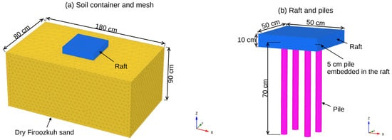
A validation model was built in PLAXIS 3D (CONNECT Edition V20, version 20.0.0.119; Bentley Systems, Inc., Exton, PA, USA, 2019) to reproduce the 1 g shaking-table experiments on a connected pile raft (CPR) foundation in dry sand reported by Saeedi Azizkandi et al. [6], who investigated the seismic response of a CPR foundation embedded in dry Firoozkuh sand under harmonic base excitation. The model geometry, material properties, and boundary conditions were created in PLAXIS 3D. The soil domain, raft, and pile dimensions were modeled using the same dimensions as in the experimental work, as shown in Figure 1.
Figure 1.
Finite-element model of the shaking-table test of Saeedi Azizkandi et al. [6] used for validation: (a) soil container and mesh, (b) raft and piles.
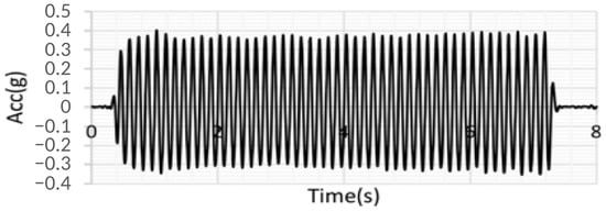
The dry Firoozkuh siliceous sand, with a relative density of about 60%, was modeled using the Mohr-Coulomb constitutive model, and the piles and raft were modeled once as linear-elastic, non-porous materials represented as volume elements; an interface element was assigned between the raft and the soil, and around the pile volume, and at another time piles were modeled as embedded beam elements; the material properties are listed in Table 1. The same harmonic load used in the physical test (0.4 g peak acceleration at 7 Hz) was implemented as a dynamic multiplier at the model boundary, and absorbing dynamic boundary conditions (free-field, compliant base) were used to emulate the energy-dissipating foam boundaries of the physical test box. This provided a consistent representation of the soil–foundation system under the same dynamic loading conditions applied in the laboratory. Figure 2 shows a typical input acceleration used in the numerical model.
Table 1.
Material properties of sand, pile, and raft of Saeedi Azizkandi et al. [6].
Figure 2.
Input acceleration employed in shaking table tests [6], reproduced under CC BY-NC-ND 4.0.
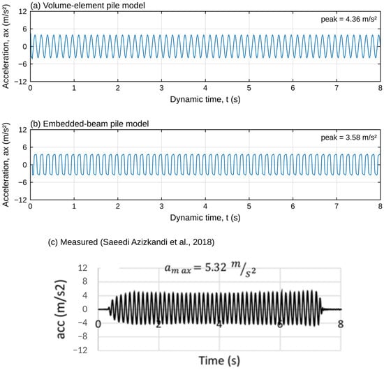
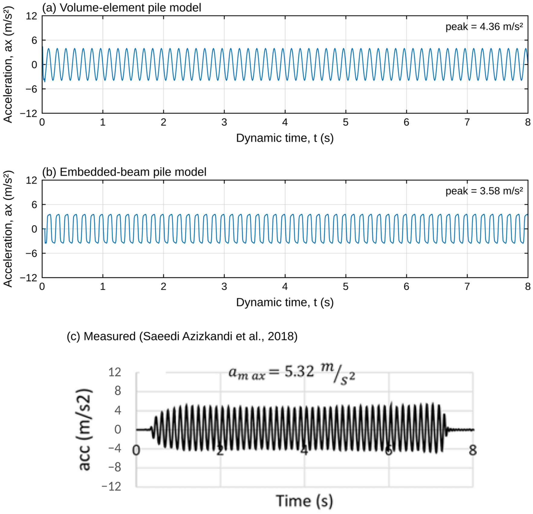
Figure 3 shows acceleration versus time for CPR in both modeling scenarios and the experimental work. The peak acceleration in the experimental study (5.32 m/s2) closely matches the peak acceleration in PLAXIS 3D (3.94 m/s2 and 3.73 m/s2 for the volume element model and embedded beam element, respectively), i.e., by approximately 26% and 30%. This discrepancy mainly arises from representing the sand with the Mohr–Coulomb model, which does not capture small-strain stiffness or its strain-dependent degradation, and from idealizing the foam boundaries of the shaking-table container as absorbing boundaries. Nevertheless, the frequency and the cyclic pattern of the measured response are reproduced, and the agreement is considered adequate for the comparative purpose of the present study, in which the foundation systems are assessed relative to one another within the same numerical framework.
Figure 3.
Acceleration time histories at the CPR raft under harmonic base excitation (0.4 g, 7 Hz): (a) volume-element pile model; (b) embedded-beam pile model; (c) measured [6].
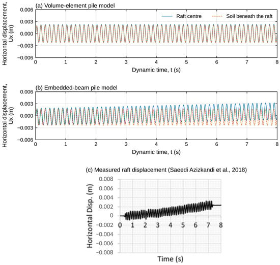
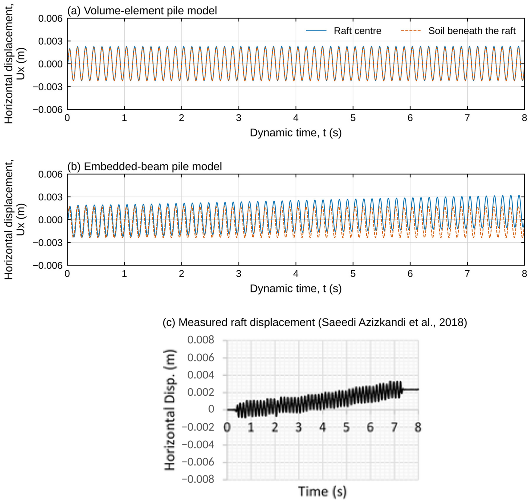
Figure 4 shows the horizontal cap displacement versus time for CPR at the center of the raft surface obtained from two pile representations and for experimental work. In the volume element model (Figure 4a), the raft and the soil move in phase with practically the same amplitude (peaks of 2.30 and 2.26 mm), and no residual displacement develops. Whereas in the embedded beam element (Figure 4b), the soil motion remains stable, whereas the center of the raft oscillation drifts at an almost constant rate of approximately 0.17 mm/s, from −0.18 to +1.03 mm over the loading, so that the positive peaks increase from 1.97 to 3.22 mm while the oscillation amplitude remains unchanged. Because the soil beneath the raft shows no drift, the accumulated displacement develops at the raft–soil contact through slip along the interface and/or raft rocking, rather than within the soil mass. This indicates that the embedded beam captured the residual displacement caused by repeated cyclic loading better than the volume element.
Figure 4.
Horizontal displacement time histories under harmonic base excitation at the center of the CPR raft and in the soil directly beneath the raft: (a) volume-element pile model; (b) embedded-beam pile model; (c) measured raft displacement [6].
In addition, the volume element model took more than 40 h to analyze the 8 s of input acceleration used in the test, even with high-performance computing. The embedded beam model finished the same analysis in just 10 h and needed far less computing power. For these reasons, the embedded-beam element was used to model the piles in the seismic analyses of this study.
2. Convergence Analysis
2.1. Boundary Convergence Analysis
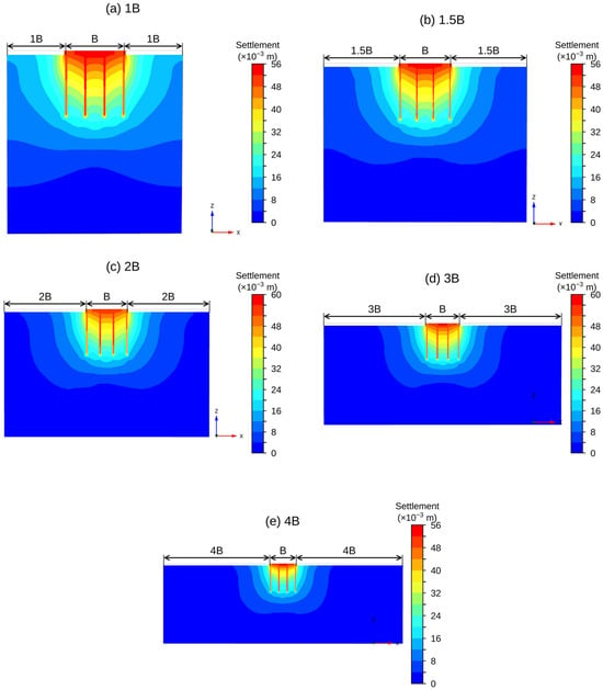
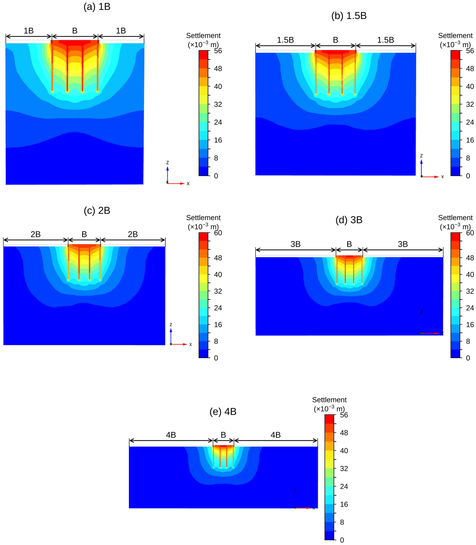
Five models were analyzed to determine the minimum lateral soil domain, with the boundary placed at 1B, 1.5B, 2B, 3B, and 4B from the raft edge (B = 15.4 m), all other parameters held constant. At 1B and 1.5B, the load-settlement response showed artificially high stiffness and underestimated settlement (Figure 5). A close, fixed boundary prevents free outward soil deformation, thereby artificially raising apparent stiffness. Results converged at 3B; 4B produced no further change. Poulos [12] recommends at least 3B for pile-raft foundations; for seismic analysis, the boundary was extended about 5.5B from the raft edge in the x-direction to reduce reflected waves back into the model and to achieve a uniform distribution and radiation damping of seismic waves.
Figure 5.
Settlement profiles at the raft center for lateral boundary distances: (a–e) of 1B, 1.5B, 2B, 3B, and 4B from the raft edge (B = 15.4 m), respectively.
2.2. Mesh Convergence Analysis
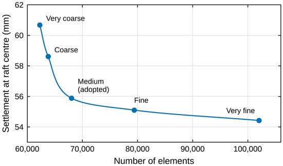
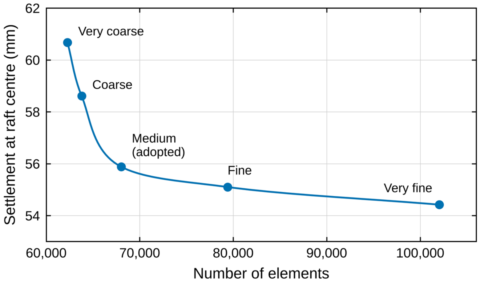
To identify the optimal mesh for accurate numerical analysis, a mesh convergence analysis was carried out under static conditions. Five mesh densities, from very coarse (62,280 elements) to very fine (102,053 elements), were tested; the results are shown in Figure 6. As mesh density increased, the settlement under the raft center decreased and converged. Using the very fine mesh as the reference, the settlement error decreased from 11.5% for the very coarse mesh to 7.7%, 2.7%, and 1.3% for the course, medium, and fine meshes, respectively. Medium mesh (68,023 elements) was therefore adopted for all analyses, with local refinement near the structural elements, as it gives a settlement within 3% of the reference value with about two-thirds of the elements of the very fine mesh.
Figure 6.
Settlement under raft center versus number of elements for the five mesh densities (very coarse to very fine) used in the mesh sensitivity analysis.
3. Numerical Modeling and Methodology
The numerical analysis was carried out using PLAXIS 3D V20, which is based on the finite element method. Soil was represented by 10-node tetrahedral (TE10) continuum elements, the raft by plate elements, and piles by embedded beam elements; interface elements were introduced at all soil-raft contact surfaces to permit relative slip and separation under load.
3.1. Constitutive Models
This study employs two constitutive models in the numerical model. To represent the soil’s stress–strain behavior, the Hardening Soil (HS) constitutive model was used for the sand and cushion. Structural elements (raft and piles) were modeled using a linear-elastic model. The Hardening Soil model [13] is an elastoplastic model with stress-dependent stiffness, separate primary loading and unload/reload moduli, and two hardening mechanisms, shear and compression. For a standard drained triaxial test, the axial strain ε1 is related to the deviatoric stress q = σ′1 − σ′3 by a hyperbola up to failure:
where σ′1 and σ′3 are the major and minor effective principal stresses (kPa), qf is the deviatoric stress at Mohr–Coulomb failure (kPa), qa = qf/Rf is the asymptotic value of the deviatoric stress (kPa), Rf is the failure ratio (typically 0.9), and E50 is the secant stiffness at 50% of qf (kPa), which is easier to obtain from triaxial tests than the initial tangent stiffness Ei.
ε1 = (1/2E50) · q/(1 − q/qa), q < qf
The stiffness increases with the confining stress through a power law:
where E50ref is the reference secant stiffness at the reference pressure pref = 100 kPa, c′ is the effective cohesion (kPa), φ′ is the effective friction angle (°), and m is the power of the stress dependency (–). The unloading–reloading stiffness Eur follows the same law. A value of m = 1.0 reproduces the logarithmic stiffness trend typical of soft clays, whereas lower values suit sands (m = 0.5 in this study).
E50 = E50ref [(c′ cos φ′ − σ′3 sin φ′)/(c′ cos φ′ + pref sin φ′)]m
The Hardening Soil model has two categories of parameters input to PLAXIS 3D: stiffness parameters and failure parameters. Stiffness parameters consist of the following four parameters: E50ref: Secant stiffness in standard drained triaxial test (kPa), Eurref Unloading/reloading stiffness (kPa), Eoedref Tangent stiffness for primary oedometer loading (kPa), and m: Power for stress-level dependency of stiffness (-). Failure parameters include: c: effective cohesion (kPa), φ: effective angle of internal friction (Degrees), and ψ: angle of dilatancy (Degrees).
The HS model is an effective-stress, rate-independent elastoplastic model with no mechanism for generating excess pore pressure under cyclic loading, and its hysteretic damping at small strains and its accumulation of strain with the number of cycles are limited. It therefore cannot reproduce the build-up of pore pressure and the loss of stiffness and strength that precede liquefaction. Accordingly, all analyses in this study are drained and interpret the effect of the groundwater level on the seismic response of piled-raft foundations under non-liquefaction conditions: the GWL acts only through the initial effective stress and the soil unit weight.
The structural elements (raft and piles) were represented by a linear-elastic model, consistent with standard practice for piled-raft serviceability analysis [4,12] since the research focus is on geotechnical response (settlement, load sharing, soil-structure interaction) rather than structural failure. Material properties adopted for the sand, the sand cushion (used in the unconnected condition), the raft, and the piles are summarized in Table 2.
Table 2.
Parameters and properties of soils, raft, and pile.
3.2. Soil Domain Size and Foundation Geometry
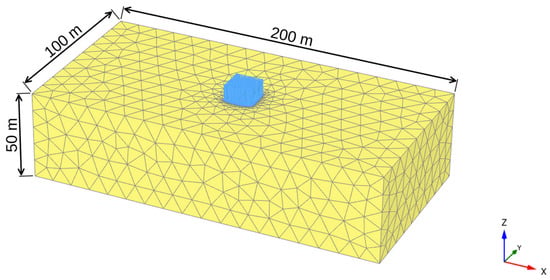
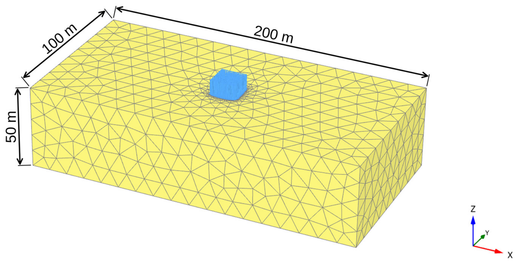
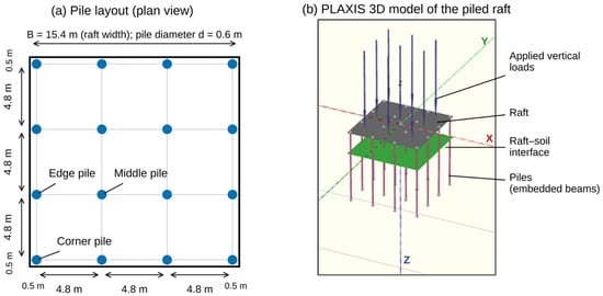
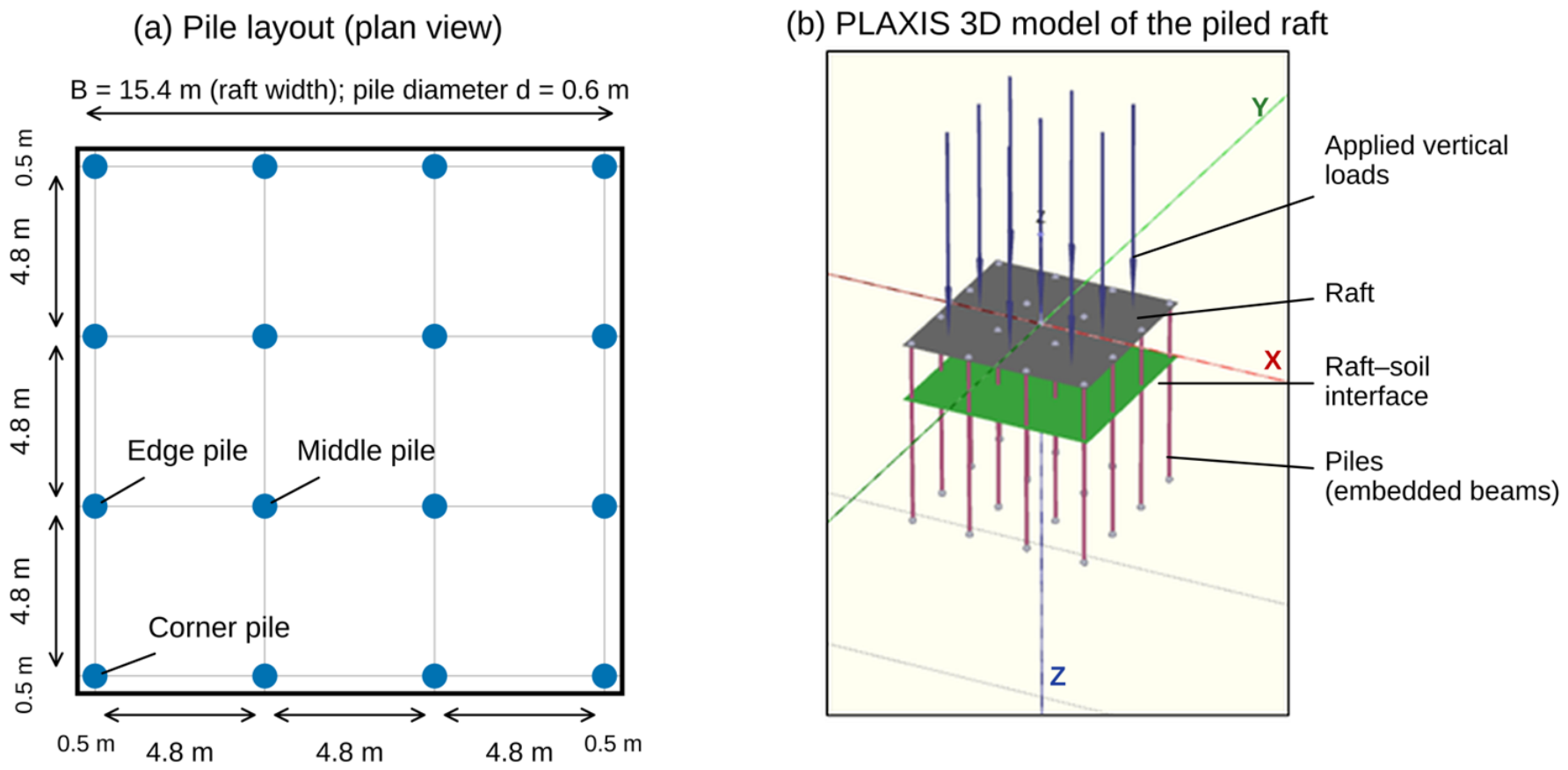
Figure 7 shows the soil domain that was used for all models of a 200 m × 100 m × 50 m (X × Y × Z) soil domain, with lateral boundaries placed at 5.5B from the raft edge to eliminate boundary confinement, and the base set 35 m below the pile tips to allow end-bearing stresses to dissipate before reaching the rigid boundary. The water table was investigated at three depths—0.5 m, 7.5 m, and 50 m. Mesh refinement was applied within a 15.4 m × 15.4 m × 15 m sub-domain around the raft, coarsening toward the outer edges. As shown in Figure 8, the foundation system used in this study consists of 16 circular piles (diameter 0.6 m, length 15 m) arranged in a 4 × 4 square pattern beneath a 15.4 m × 15.4 m raft of 1.5 m thickness. Vertical load representing self-weight and service loads of a high-rise building; for the chosen scenario of a 14-story commercial building, the total load exerted on the raft as a distributed load would be 300 kN/m2. The response of the raft is investigated at its center (raft center), and the input motion is monitored at the base of the soil model (soil base), on the same vertical axis.
Figure 7.
Three-dimensional soil model (200 m × 100 m × 50 m) and refined mesh zone around the foundation (yellow); the blue block represents the applied vertical load.
Figure 8.
Foundation geometry: (a) 4 × 4 group of piles (d = 0.6 m, L = 15 m) beneath a 15.4 m × 15.4 m × 1.5 m raft, (b) PLAXIS 3D model of the piled raft.
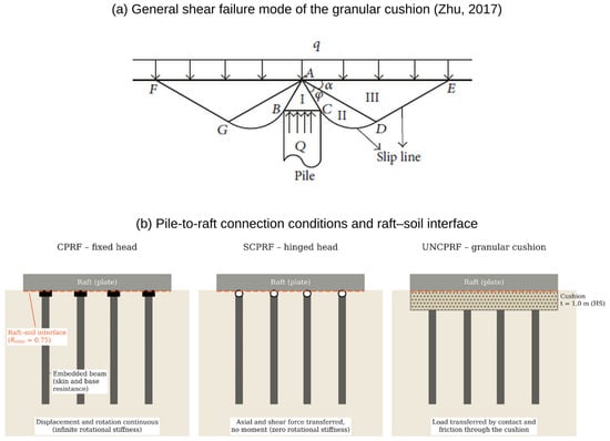
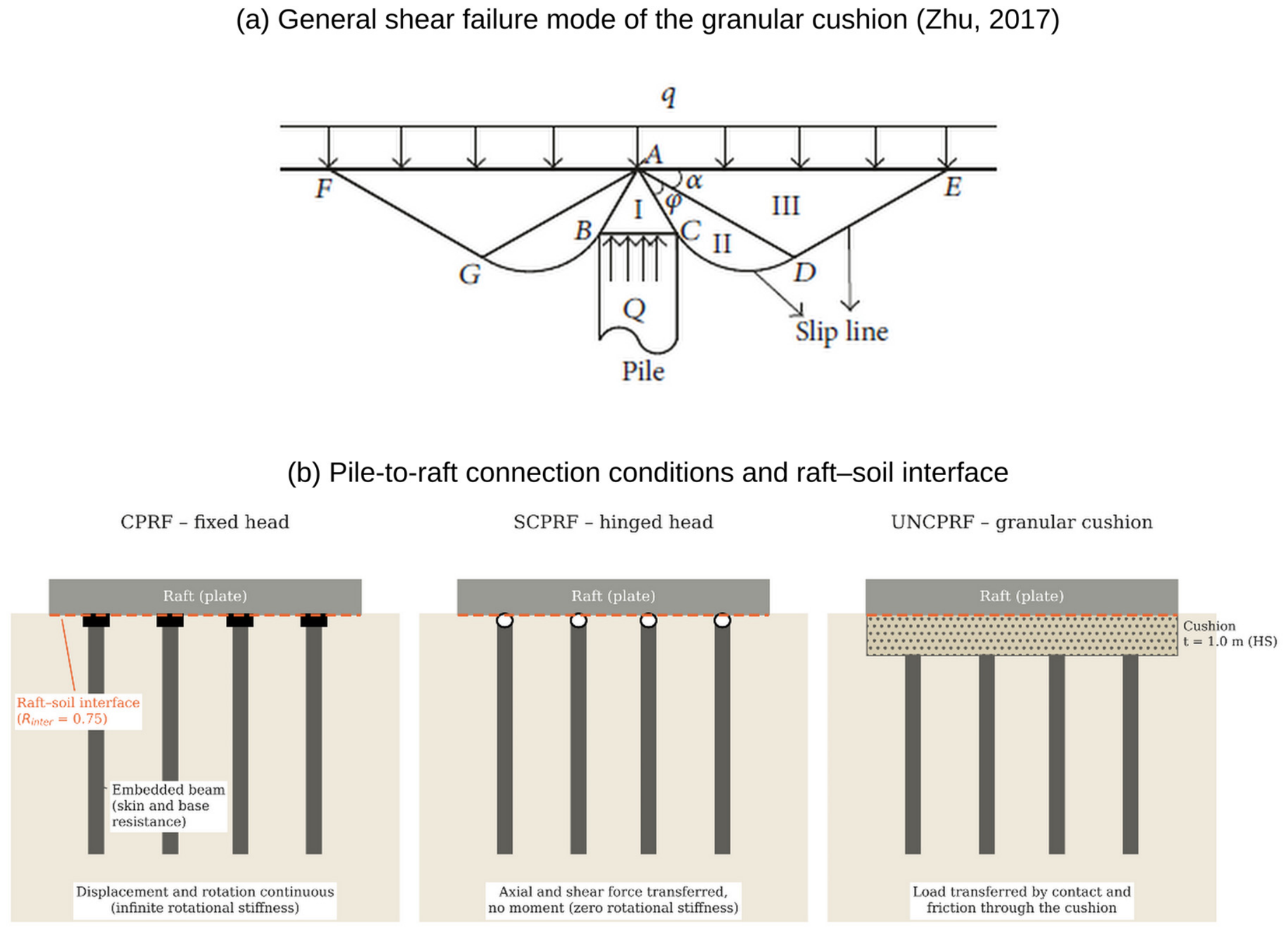
This study models three pile-to-raft connection types. The simulation of the connection condition is based on the connection type; for CPRF, the connection is established by selecting (Fixed) as the pile head connection type in the embedded beam material settings, while the (Hinged) option of the pile head connection type in the embedded beam material simulates the SCPRF [14]. An interface element is illustrated between the raft and the surrounding soil to introduce flexibility and allow relative movement. In modeling the UNCPRF, a compacted coarse sand or gravel cushion is placed between the pile heads and raft base [15,16,17], modeled with a Hardening Soil material at substantially lower stiffness than the concrete—creating a compliant connection that limits moment transfer while still passing axial load into the piles. Cushion thickness governs the contact pressure distribution and must be enough to let the raft deform independently of the piles [5,18], with the minimum set by the cushion’s general shear failure condition ([19]; Figure 9a): t ≥ d/2 · cot α where d is the pile diameter, and α is the active failure angle. In Figure 9a, q is the uniform pressure transmitted by the raft, Q is the pile-head reaction, zones I–III are the wedge above the pile head, the radial shear zone and the passive zone, respectively, and points A–G define the slip surfaces. A 1 m thickness was adopted here, following El Kamash et al. [18] as the optimum, lowest-cost value. These three connection conditions were compared against an un-piled raft-only (RF) reference case.
Figure 9.
(a) General shear failure mode of the granular cushion in the UNCPRF, used to define the minimum cushion thickness [19]; (b) Modeling of the pile-to-raft connection conditions and of the raft–soil interface.
The piles are represented by embedded beam elements, with soil-structure interaction governed by elastoplastic skin-friction limits (Tskin, start = 0 kN/m, Tskin, end = 96.3 kN/m) and base resistance (Fmax = 1166 kN) derived from the Meyerhof [20] method. The fixed pile-head connection of the CPRF transmits moments and enforces rotational continuity with the raft, whereas the hinged connection of the SCPRF transmits axial and shear forces but no moment ([14]; Figure 9b, in which the black rectangles and white circles denote the fixed and hinged connections, respectively); the connection condition is known to govern load sharing and pile bending moments [5,8]. Friction and slip at the raft–soil contact are represented by Mohr–Coulomb interface elements with Rinter = 0.75 (Table 2). In PLAXIS, the pile-head condition of the embedded beams was set to fixed for CPRF and hinged for SCPRF, so CPRF and SCPRF represent the upper and lower bounds of the connection stiffness; a semi-rigid detail with partial moment transfer was not modeled. In the UNCPRF, force transfers between the pile heads and the raft occur only through the cushion and its interface.
4. Input Ground Motions and Boundary Conditions
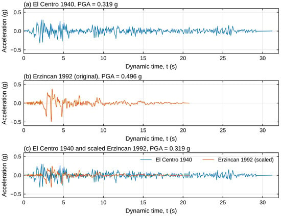
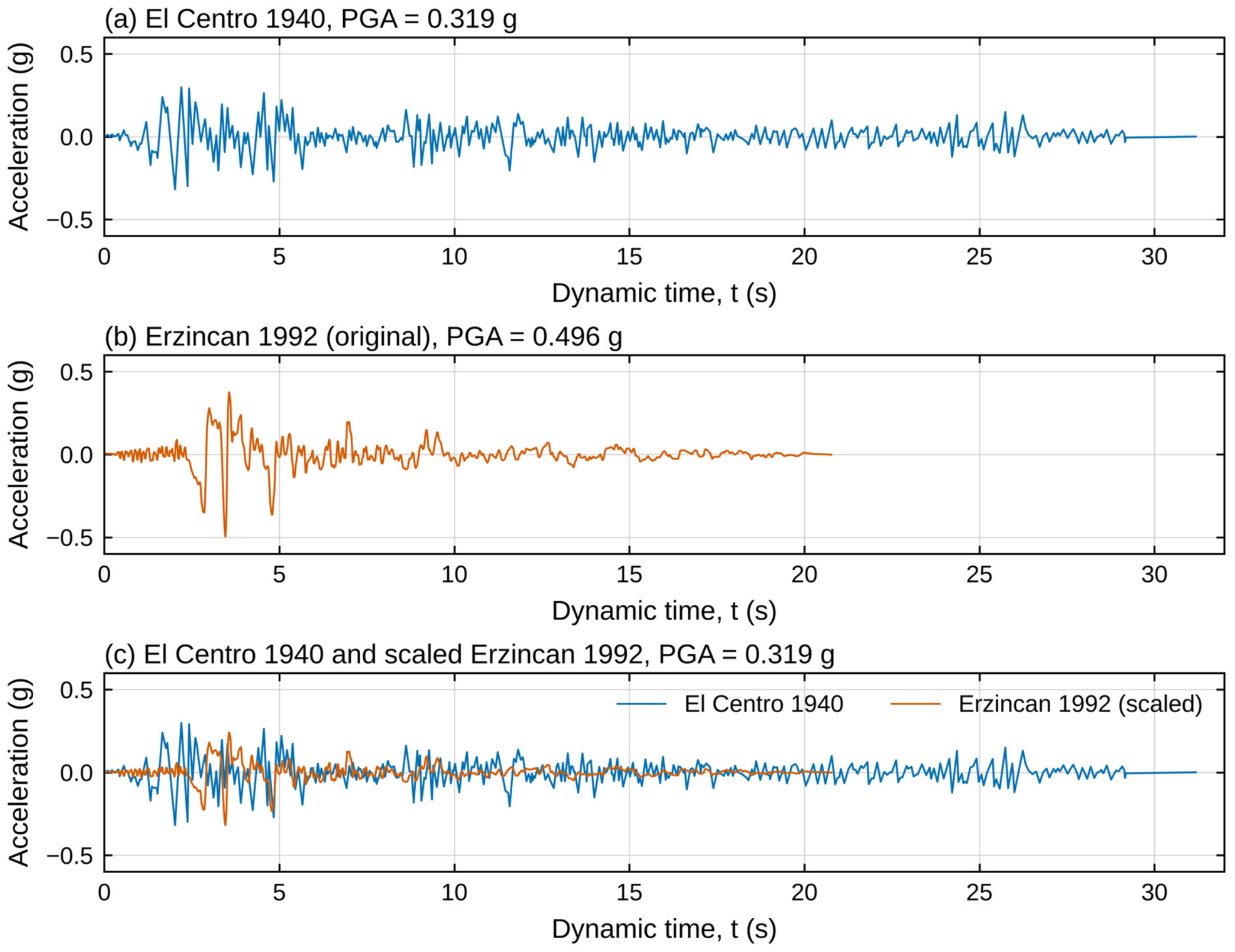
In this study, two earthquake records were selected. The 1940 El Centro record (Mw 6.9, PGA = 0.319 g) was adopted as the primary motion because it is a widely used benchmark in seismic soil–structure interaction studies. The 1992 Erzincan record (Mw 6.7, PGA = 0.496 g), from the North Anatolian Fault zone in eastern Türkiye, was added as a near-fault, pulse-dominated motion of shorter duration (20.8 s against 31.2 s), which therefore differs markedly in character from the El Centro record. Figure 10 shows the time-acceleration histories and PGAs for the different earthquake motions; Figure 10a represents the 18 May 1940 Imperial Valley (El Centro) record with PGA = 0.319 g, and Figure 10b represents the 13 March 1992 Erzincan (Türkiye) record with PGA = 0.496 g. To separate the influence of ground-motion characteristics from that of intensity, the Erzincan record was used in two versions (Table 3): the original record (PGA = 0.496 g) and a version scaled by 0.643 to match the PGA of El Centro (0.319 g) (Figure 10c). Comparing the El Centro record with the scaled Erzincan record isolates the effects of frequency content, duration, and pulse at equal PGA, whereas comparing the Erzincan record −0.496 with the scaled Erzincan record −0.319 isolates the effect of intensity for the same record shape.
Figure 10.
Input motions at the soil base: (a) acceleration time histories of the El Centro 1940, (b) acceleration time histories of the Erzincan 1992, and (c) acceleration time histories of the El Centro 1940 and scaled Erzincan 1992 motions (PGA = 0.319 g).
Table 3.
Characteristics of the input motions at the soil base.
Table 4 lists the 21 three-dimensional dynamic analyses performed. In the dry condition (GWL = −50 m), the four foundation systems (RF, CPRF, SCPRF and UNCPRF) were analyzed under El Centro and under Erzincan at both intensities (0.319 g and 0.496 g). The saturated conditions were added for El Centro (GWL = −0.5 m and −7.5 m) and for the scaled Erzincan record (GWL = −0.5 m) only. The groundwater level was only varied for the 0.319 g motions, because stronger shaking increases the likelihood of excess pore-pressure generation, which the Hardening Soil model cannot represent.
Table 4.
Summary of the analyzed cases (ground motion, foundation system, and GWL).
To compare the behavior of the systems under the two records independently, the response of each system is normalized by that of the raft-only case (RF) under the same record:
and the difference between the Erzincan (ER) and El Centro (EC) records is expressed by the difference ratio:
where X is the response considered, R is the normalized response (-), RER and REC are the normalized responses under the Erzincan and El Centro records, respectively, and DR is expressed in %. The sign of DR is read as follows:
R = XSystem/XRF
DR = (RER − REC)/REC × 100
DR ≈ 0: the foundation modifies the response in the same proportion under both records;
DR > 0: the response relative to the RF is larger under Erzincan, i.e., the benefit of the foundation is smaller;
DR < 0: the response relative to the RF is smaller under Erzincan, i.e., the benefit is larger.
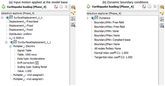
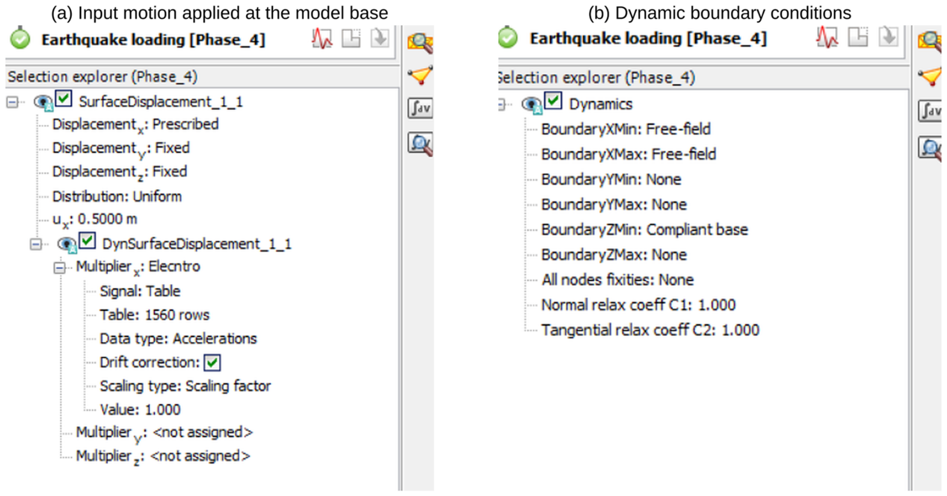
The records were applied as a dynamic multiplier of surface displacements at the base of the soil domain, as shown in Figure 11a. Absorbing (free-field, compliant-base) dynamic boundary conditions were used to minimize spurious wave reflection back into the model, as shown in Figure 11b. Because seismic wave propagation is more sensitive to lateral boundary placement than static loading, the lateral extent of the soil domain was increased to approximately 5.5 times the raft width (compared with the 3B minimum recommended for static analyses, established through a dedicated boundary-convergence study) to achieve a uniform radiation-damping response. A medium mesh density, selected based on a mesh-convergence study across five refinement levels, was adopted for all analyses, with local refinement beneath and around the raft and piles.
Figure 11.
(a) Application of the input motion as a prescribed displacement at the base of the model; (b) dynamic boundary conditions (free-field lateral boundaries and compliant base).
5. Results and Discussion
The seismic analysis of pile-raft foundation systems is presented in three parts: (I) the seismic response of the four foundation systems (RF, CPRF, SCPRF, UNCPRF) in the dry condition under the El Centro and Erzincan records; (II) the sensitivity of the connected, semi-connected, and unconnected systems to groundwater level depth; and (III) a comparison with the response to the Erzincan record, at two intensities. The responses are the horizontal displacement (Ux), vertical displacement (Uz), and lateral acceleration (ax) at the raft center, and the bending moments of the piles about the two local axes of the embedded beams (M3 and M2).
5.1. Seismic Response Under El Centro and Erzincan Records (Dry Condition)
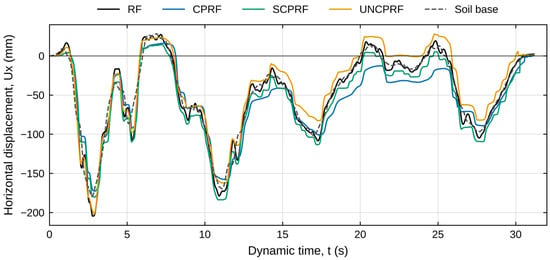
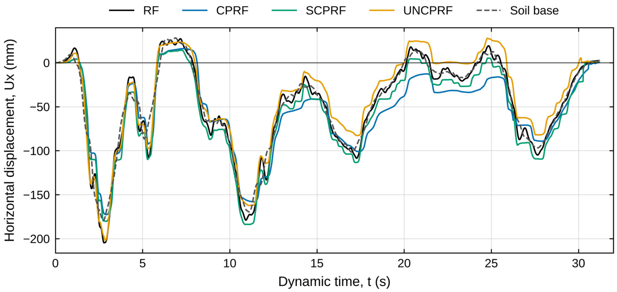
Figure 12 shows the time history of horizontal displacement at the center of the raft surface of CPRF, UNCPRF, and SCPRF with the displacement of the soil base (dashed line), showing that the peak lateral displacement for all systems occurs at approximately t = 2.8 s, and the base motion is similar in the four models, with a negative peak of 179–190 mm at about 2.7 s. The RF system exhibited the largest peak lateral displacement (204.69 mm). The UNCPRF produced an essentially identical peak displacement (202.32 mm), a 1.16% reduction relative to RF, indicating that an unconnected pile group is largely ineffective at reducing peak seismic lateral demand because the cushion layer decouples pile stiffness from raft response. The SCPRF reduced the peak displacement to 183.8 mm (10.3% reduction relative to RF), attributable to the lateral restraint transmitted through the hinged pile heads, which transfer shear forces even without moment continuity. The CPRF produced the lowest peak displacement (172.75 mm), a 15.6% reduction relative to RF and a further 6.1% improvement over SCPRF, confirming that a rigid pile-head connection is required to mobilize meaningful lateral stiffness from the pile group under seismic loading [8]. This behavior is consistent with the lateral restraint provided to the raft by structurally connected piles, which is largest for the fixed head [4,8]. For the RF and UNCPRF, the raft is laterally supported only by friction at the raft–soil or raft-cushion contact, consistent with the cushion acting as a partial isolation layer between the raft and the piles [3,7].
Figure 12.
Time histories of horizontal displacement (Ux) at the center of the raft surface for the systems under dry conditions (El Centro record, PGA = 0.319 g).
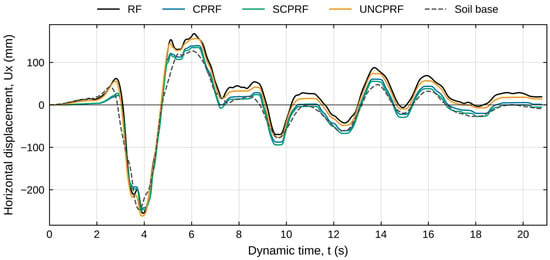
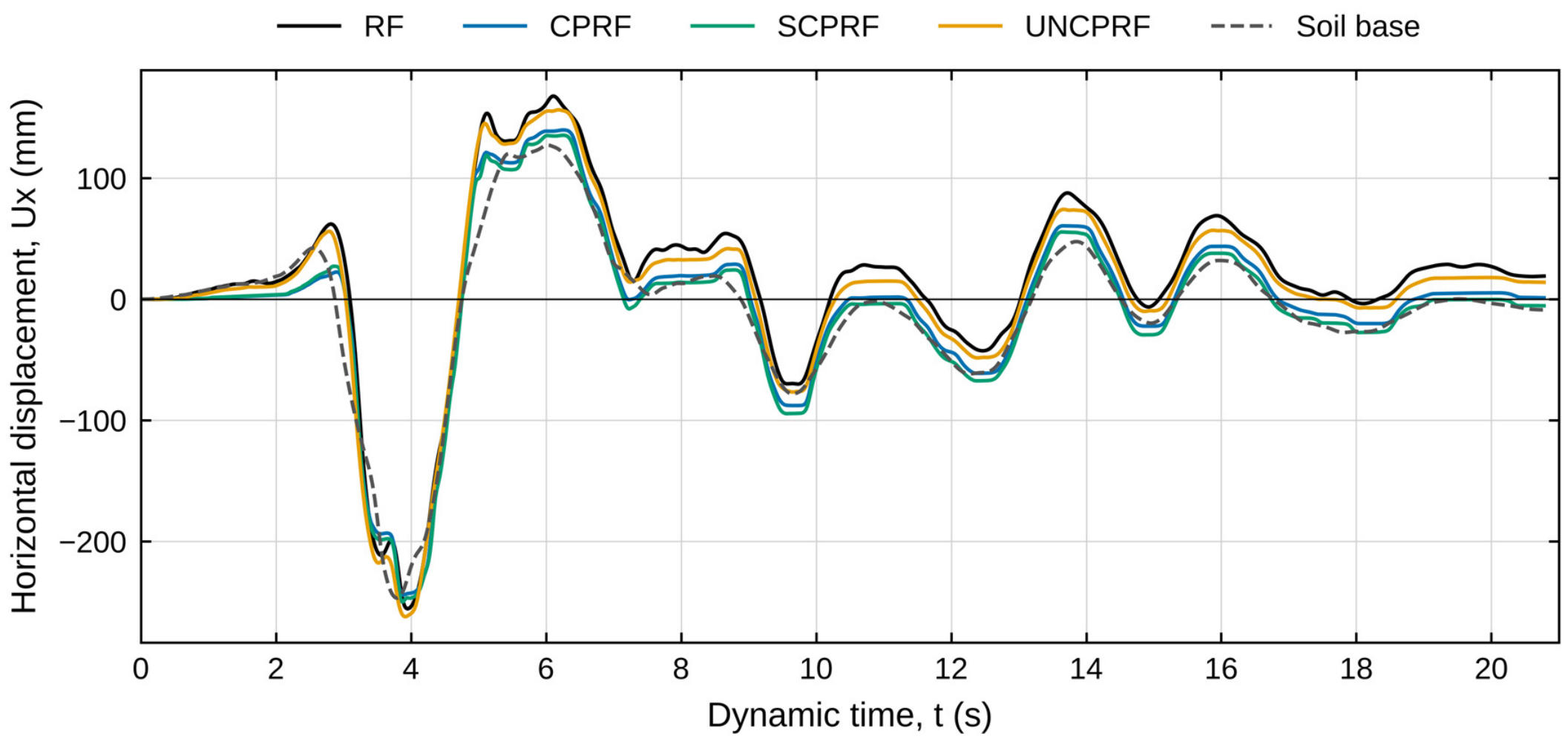
Figure 13 shows the horizontal displacement response under the Erzincan record at its original intensity (dry condition), which is practically identical in the four models (negative peak of 247–256 mm at 3.7–3.8 s and positive peak of 121–132 mm at about 6 s; spread within 4%), confirming the same input in all analyses. The raft follows the ground during the dominant negative pulse: its peak at about 3.9 s is 255.6 mm for the RF and 244.2, 249.8 and 262.1 mm for the CPRF, SCPRF and UNCPRF (within ±5% of the RF), so the largest absolute displacement is imposed by the ground motion and is hardly modified by the foundation. The systems separate during the positive swing at about 6.2 s, where the RF reaches 167.8 mm and the UNCPRF 156.4 mm (−7%), whereas the CPRF and SCPRF reach only 139.8 and 135.4 mm (−17% and −19%), close to the soil base, and at the end of the record, where the RF and UNCPRF retain a displacement relative to the soil base of 29 and 21 mm against 14 mm (CPRF) and 10 mm (SCPRF). The displacement relative to the soil base reaches its peak at about 3.0 s, when the base moves rapidly toward the main pulse and the raft lags behind it: 84.9 mm for the RF and 75.6, 76.8, and 66.2 mm for the CPRF, SCPRF, and UNCPRF (−11%, −10%, and −22% relative to RF).
Figure 13.
Time histories of horizontal displacement (Ux) at the center of the raft surface for the systems under dry conditions (Erzincan record, PGA = 0.496 g).
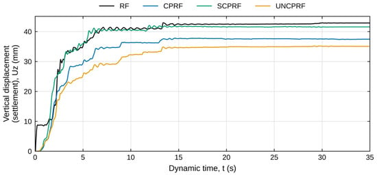
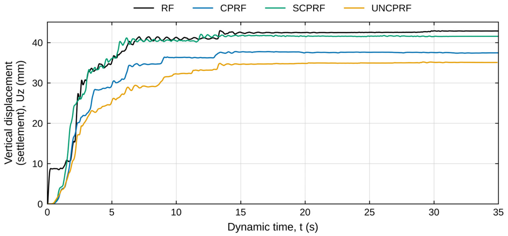
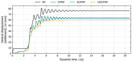
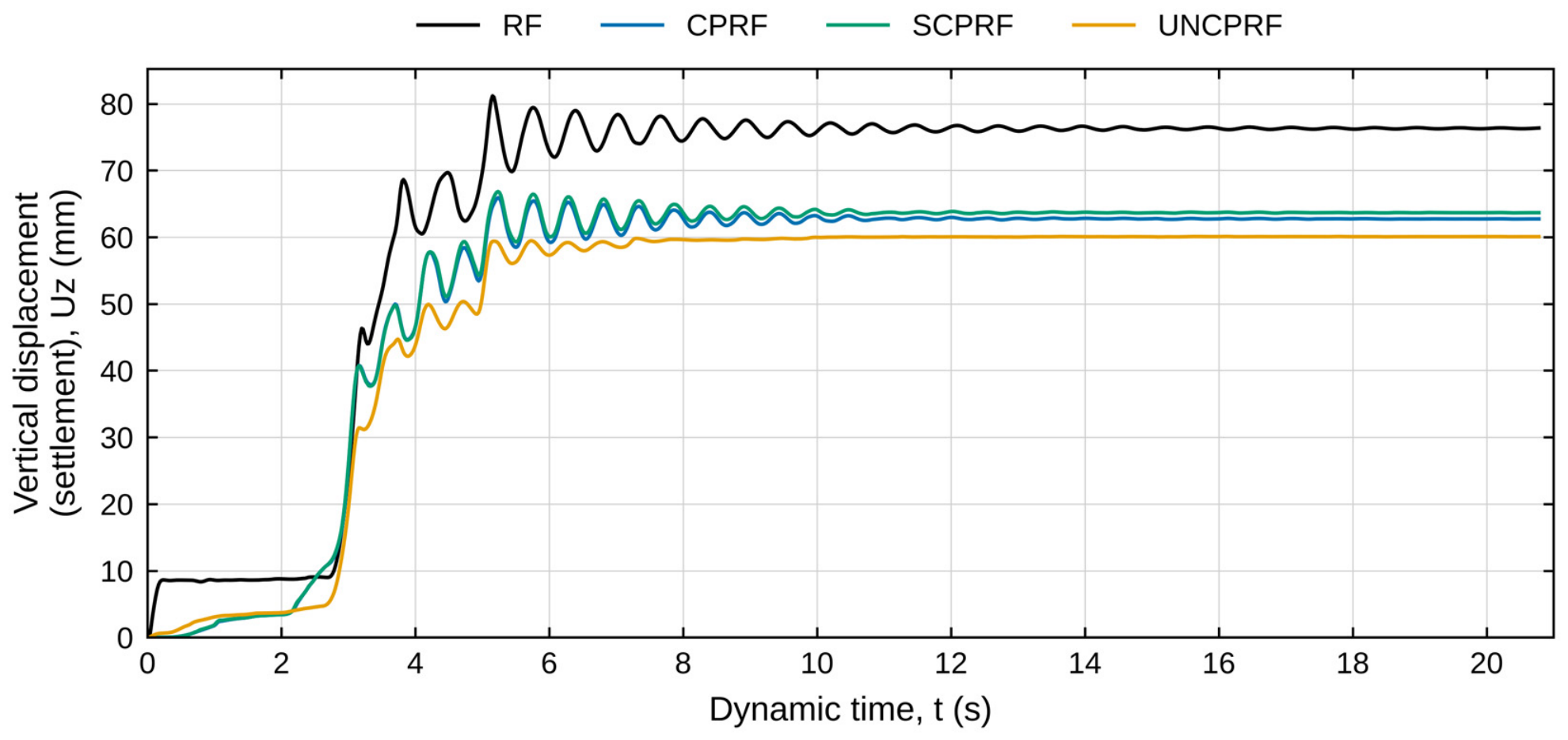
The vertical settlement time history under El Centro in Figure 14 provides complementary insight into foundation performance under seismic loading; settlement develops in steps during the strong-shaking phase and levels off after about 14 s, with no recovery once shaking decays. This pattern is characteristic of seismic compaction of sand, in which cyclic shear strains rearrange the grains into a denser packing and the resulting vertical strain depends mainly on the shear-strain amplitude [21,22]. The settlement of the raft-only case (42.94 mm) is therefore governed by the compaction of the upper sand layer rather than by the foundation system, and the piles reduce it moderately: by 18.5% in the UNCPRF (35.0 mm), 12.1% in the CPRF (37.76 mm) and only 2.9% in the SCPRF (41.7 mm), the reduction in the CPRF being consistent with the rigid connection mobilizing the axial stiffness of the pile group. Figure 15 shows the vertical displacement of the raft under the Erzincan record at its original intensity (dry condition). The peak settlement is 81.2 mm for the RF and 65.9, 66.8, and 60.1 mm for the CPRF, SCPRF, and UNCPRF, corresponding to reductions of 18.8%, 17.7%, and 26.0% relative to the RF. The final settlements are 76.4, 62.7, 63.7, and 60.1 mm, respectively, so that 94–100% of the peak settlement is permanent. In both cases, the RF settles the most, and the UNCPRF settles the least (35.0 mm under EL Centro and 60.1 mm under Erzincan); the seismic settlement is almost entirely permanent. Decoupling the direct structural contact between the pile heads and the raft with an interposed granular cushion (UNCPRF) reduces excessive structural constraints, resulting in lower settlement during earthquakes than conventional CPRF systems [3,6].
Figure 14.
Time histories of vertical displacement (Uz) at the center of the raft surface for the systems under dry conditions (El Centro record, PGA = 0.319 g).
Figure 15.
Time histories of vertical displacement (Uz) at the center of the raft surface for the systems under dry conditions (Erzincan record, PGA = 0.496 g).
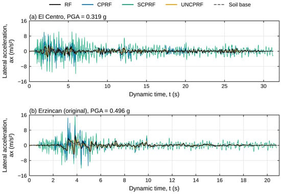
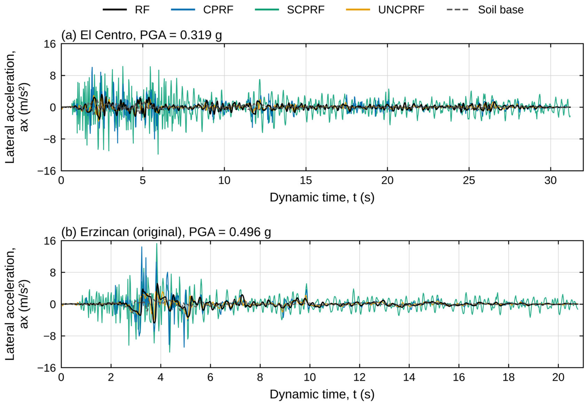
Figure 16 shows the lateral acceleration time history at the raft center and the soil base under the El Centro and Erzincan records (dry condition). Under El Centro, among the piled systems, the RF and UNCPRF produced the lowest peaks (3.21 and 3.56 m/s2, about 1.6 and 1.8 times the soil-base value); friction along the pile shafts dissipates energy before it reaches the raft. Whereas the CPRF and SCPRF peaked at 10.05 and 11.86 m/s2 (about 4.7 and 5.8 times), reflecting how a more rigid pile-raft connection amplifies transmitted acceleration. Under the Erzincan record, the peaks occur during the near-fault pulse (3.2–3.9 s) and follow the same pattern. The UNCPRF and RF reached 4.04 and 5.19 m/s2 (1.5 and 2.0 times the soil-base value), and the CPRF and SCPRF reached 14.42 and 15.27 m/s2 (5.3 and 5.7 times). The amplification ratio is therefore similar for both systems under the two records, although the PGA and frequency content differ (Table 3). In the RF and UNCPRF, the raft is not structurally connected to piles; shear strength at the raft–soil or raft–cushion interface limits the horizontal force transmitted to the raft, consistent with their low amplification (1.5–2.0). In the CPRF and SCPRF, the structural connection transmits the stiff pile group response directly to the raft, consistent with the spectral peak shifting to shorter periods.
Figure 16.
Time histories of lateral acceleration (ax) at the raft center for the systems and the soil base under dry conditions: (a) EL Centro record, PGA = 0.319 g; (b) Erzincan record (original), PGA = 0.496 g.
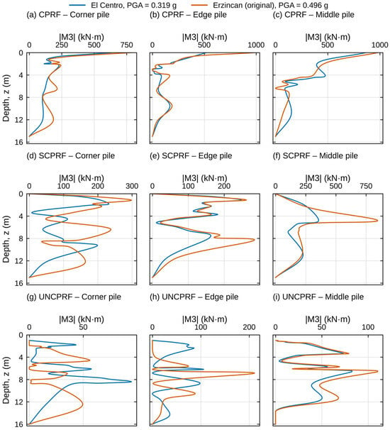
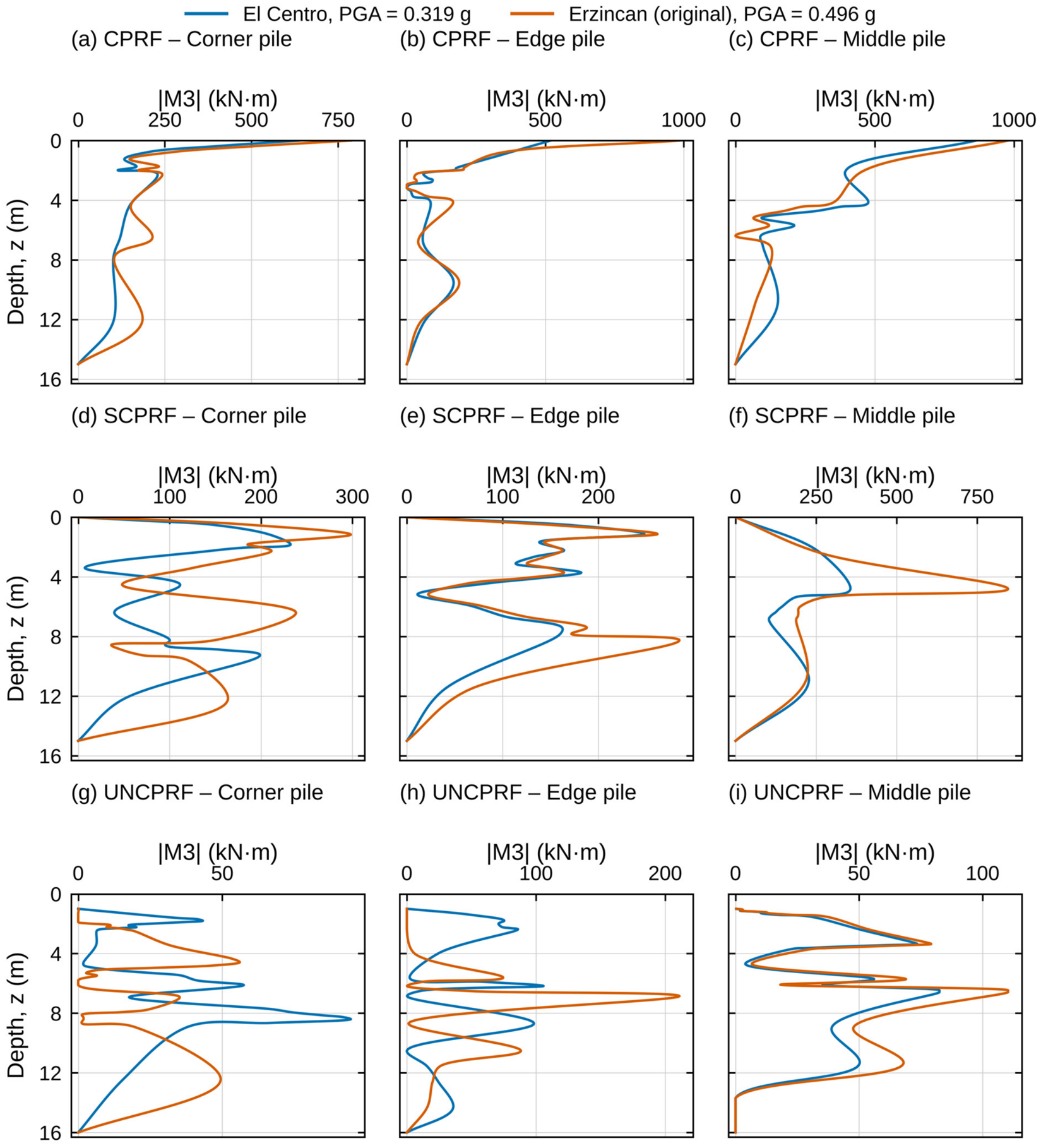
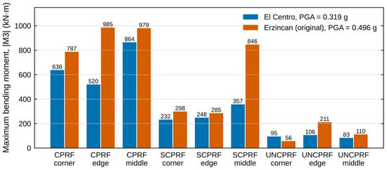
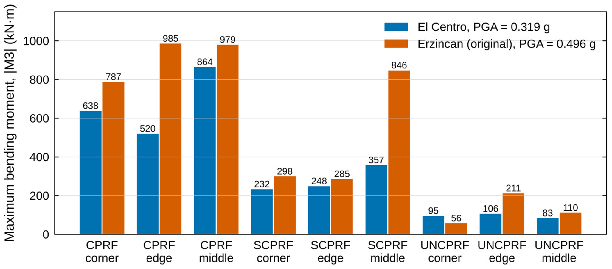
Figure 17 shows the bending moments along the piles under the two records, and Figure 18 compares their maximum values. The moments are presented as absolute values of the maximum-absolute envelope over the record, as their sign depends on the direction of shaking at the instant of the maximum and is not comparable between the two records. In the CPRF, the highest moments consistently occur at the pile head for all pile positions under both records and reach 638, 520, and 864 kN·m in the corner, edge, and middle piles under El Centro, and 787, 985, and 979 kN·m under Erzincan, consistent with the mechanism reported by Halder et al. [8]. In the corner and edge piles it falls to 20–35% of the head value within 2 m before decreasing progressively to near zero at the pile toe, whereas in the middle pile it remains at about 45% at 2 m and shows a second peak at 4 m (477 kN·m under El Centro). In the SCPRF, the moment is likewise concentrated near the pile head, about 1–2 m in the corner and edge piles and to 4.8 m in the middle pile, absence of moment transfer at the hinged head limits the corner-pile maximum to approximately ±300 kN·m under both records—roughly a 50% reduction relative to the CPRF corner pile—decreasing to near zero toward the toe. In the UNCPRF, the absence of a mechanical connection eliminates inertial moment transfer at the head; the moment instead builds gradually from zero, peaks at mid-to-lower shaft depths of about 7–8 m, and is roughly eight times lower (about 88%) than the CPRF peak under El Centro. This systematic shift in peak bending moment location—from the pile head in CPRF to the mid-shaft in UNCPRF as connection rigidity decreases—has direct implications for detailing longitudinal pile reinforcement.
Figure 17.
Distribution of the maximum absolute bending moment |M3| along the corner, edge, and middle piles of the CPRF, SCPRF, and UNCPRF under dry conditions (El Centro, PGA = 0.319 g; Erzincan, PGA = 0.496 g).
Figure 18.
Maximum absolute bending moment |M3| of the corner, edge, and middle piles under El Centro (PGA = 0.319 g) and Erzincan (PGA = 0.496 g), dry condition.
The stronger record does not scale the moments uniformly; in the CPRF, moments increase by a factor of 1.1–1.9, 1.2–1.3 in the SCPRF corner and edge piles, and 2.4 in the middle pile, while the UNCPRF corner pile decreases by 41%. The maximum depth in the middle piles is the same under both records (4.8 m in the SCPRF, 6.5 m in the UNCPRF), so the intensity changes in magnitude but not in position. As a result, the hinged head reduces the middle-pile moment to 41% of the CPRF value under El Centro but only to 86% under Erzincan, so that, in the present analyses, the moment demand does not follow the PGA alone, in line with the dependence of pile bending on the frequency content and number of cycles of the motion [23].
The Erzincan record was scaled by a factor of 0.643 to the PGA of El Centro (ER-0.319) to separate the effect of differences in intensity (PGA of 0.496 g against 0.319 g) and in frequency content. This allows for a comparison of the groundwater analyses, limited to this PGA to avoid excess pore pressure, between two records of equal intensity. Table 5 summarizes the seismic response analysis results for the four pile-raft foundation systems (RF, CPRF, SCPRF, and UNCPRF) under dry (baseline) conditions under the El Centro record, PGA = 0.319 g, and Erzincan, PGA = 0.496 g. The CPRF and SCPRF reduce the absolute displacement under ER-0.319 by 12.8% and 12.5% with respect to the RF (171.5 mm), whereas the UNCPRF does not (−0.3%); the UNCPRF is, however, the only system that appreciably reduces the displacement relative to the soil base (by 21.7%, against 0.5–2.0%) and, as under the original record, the settlement (by 28.2%, against about 4% for the connected systems). The raft acceleration of the CPRF and SCPRF reaches 7.5 and 12.2 times that of the soil base, against 1.8 and 1.4 for the RF and UNCPRF, and the maximum pile moments are 1004, 479 and 168 kN·m in the CPRF, SCPRF and UNCPRF, respectively.
Table 5.
Summary of the peak seismic response of the four foundation systems under dry conditions (El Centro and Erzincan records): (a) displacements and accelerations; (b) maximum pile bending moments.
The normalized response R (Equation (3)) and the difference ratio DR (Equation (4)) of the three piled systems under Erzincan at its original intensity with respect to El Centro and El Centro with Erzincan scaled to the same PGA are illustrated in Table 6a and Table 6b, respectively. In Table 6a, the displacement DR for the CPRF and SCPRF is greater than zero, indicating that the benefit of the connected piles is smaller under Erzincan (R rises from 0.84 and 0.90 to 0.96 and 0.98, respectively), as the displacement is imposed mainly by the ground under the stronger record; for the UNCPRF, DR is +3.7%, so that its behavior is practically unchanged. For displacement relative to the soil base, the UNCPRF is again insensitive to the record (DR = +1.6%), whereas the CPRF and SCPRF show larger benefits under Erzincan (DR of −18.6% and −9.5%. For settlement, the piles under Erzincan show a larger benefit because RF settlement increases more with intensity (from 42.9 to 81.2 mm) than that of the piled systems. The ranking of the systems is preserved under both records; the CPRF gives the lowest displacement, and the UNCPRF the lowest displacement relative to the soil base and the lowest settlement; however, in all cases, the benefit depends on the record. The lower settlement observed in the UNCPRF across the three earthquake records is consistent with the presence of the granular cushion, which serves to absorb seismic waves and structurally decouple the raft–pile interface, thereby mitigating shear forces and bending moments transferred to the pile heads [3,7].
Table 6.
Normalized response of the piled systems (R) and difference ratio between the records (DR) for the records’ dry condition, (a) EL Centro, PGA = 0.319 g vs. Erzincan, PGA = 0.496 g, (b) EL Centro, PGA = 0.319 g vs. Erzincan-scaled, PGA = 0.319 g.
In Table 6b, the absolute displacement, DR, is small in all three systems, so at equal PGA the foundations reduce displacement by roughly the same proportion under both records; the smaller benefit under the original Erzincan record reflects its higher intensity. For displacement relative to the soil base, the UNCPRF and SCPRF are practically unchanged, whereas the CPRF benefit is larger under Erzincan even at equal PGA and increases with intensity, so it depends on the record characteristics. For settlement, the UNCPRF benefits more under Erzincan at both intensities, a record characteristic, whereas the CPRF and SCPRF show positive or negligible DR at equal PGA and a larger benefit only at the original intensity, which is intensity-dependent.
5.2. Seismic Response with the Effect of Groundwater Level
Three groundwater level (GWL) positions were examined to assess their influence on the seismic performance of the pile-raft foundation system: (1) GWL at −0.5 m (near surface, high saturation), (2) GWL at −7.5 m (intermediate depth, partially saturated), and (3) GWL at −50 m (effectively dry, deep-water table) under El Centro, and at −0.5 m and −50 m under the Erzincan record scaled to the PGA of El Centro (PGA = 0.319 g for both records), and the differences between them reflect the characteristics of the motion and not its intensity. The RF was not analyzed with water, and all the results refer to the raft center. The analysis covers all three foundation configurations (CPRF, SCPRF, and UNCPRF) and evaluates their response at the raft center.
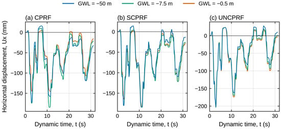
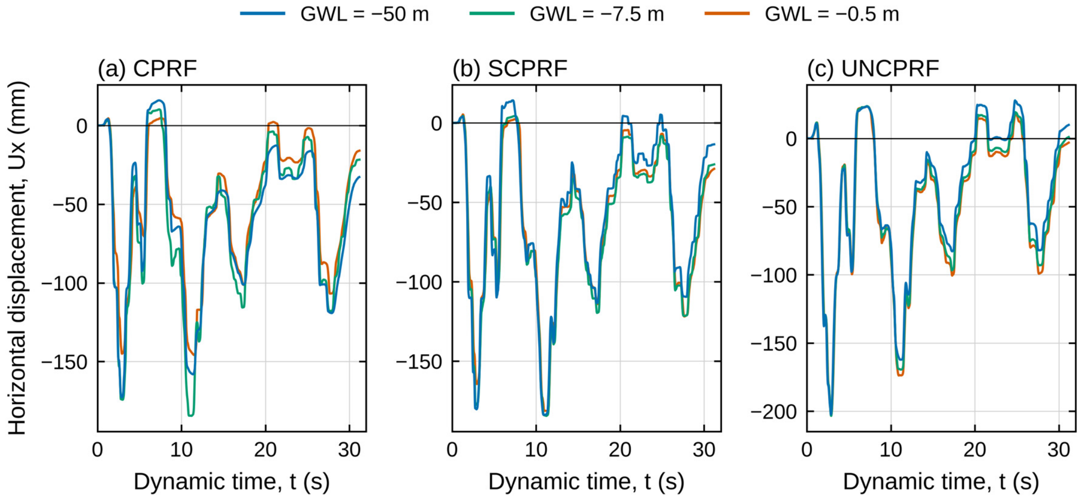
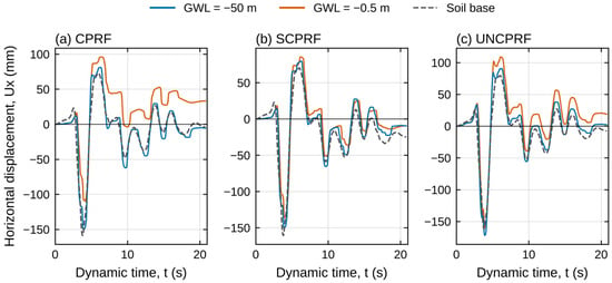
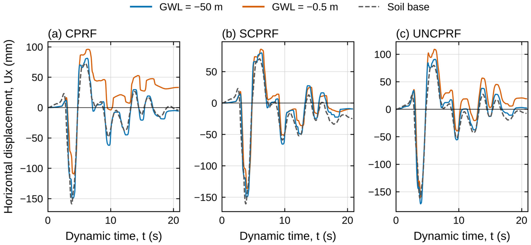
Figure 19 shows the horizontal displacement at raft level (Ux) under the El Centro record. The peak absolute displacement is sensitive to the GWL in the CPRF but practically insensitive in the SCPRF (181.4–184.4 mm) and the UNCPRF (about 203 mm). In the CPRF, the peak decreases from 172.75 mm in the dry condition to 145.87 mm at GWL = −0.5 m (−15.6%), whereas it increases slightly at −7.5 m (184.51 mm). This reduction cannot be attributed to increased damping, since in the drained analyses the presence of water does not introduce any additional energy dissipation. Instead, raising the water table reduces the effective stress and, hence, the stress-dependent stiffness of the sand (Equation (2)), which modifies the soil column response and the phase relationship between raft motion and the soil base. As shown for the Erzincan record (Figure 20), a lower peak absolute displacement therefore does not indicate a smaller deformation of the soil–foundation system. Across all GWL conditions, the UNCPRF records the largest lateral displacement, followed by the SCPRF and the CPRF, as in the dry condition.
Figure 19.
Effect of the groundwater level on the horizontal displacement at the raft center under the El Centro record (PGA = 0.319 g): (a) CPRF; (b) SCPRF; (c) UNCPRF.
Figure 20.
Effect of the groundwater level on the horizontal displacement at the raft center and at the soil base under the Erzincan record scaled (PGA = 0.319 g): (a) CPRF; (b) SCPRF; (c) UNCPRF.
Under Erzincan-scaled records, raising the water table to −0.5 m (Figure 20) reduces the raft’s largest negative excursion in the first strong pulse, particularly in the CPRF, and slightly delays it. This reduction does not indicate smaller foundation movement: the following positive excursion increases, and at the end of shaking the CPRF and UNCPRF remain permanently displaced, whereas in the dry condition they return close to their initial position. The SCPRF follows practically the same path in both conditions. The soil-base displacement (dashed lines) is practically unchanged by the water table (peaks of 158.7–164.1 mm). Expressed relative to the soil base, the peak displacement increases from 50.7 to 78.6 mm (+55.0%) in the CPRF, from 51.5 to 61.6 mm (+19.6%) in the SCPRF and from 40.5 to 59.5 mm (+46.9%) in the UNCPRF. The lower peak displacement with the water table therefore reflects the motion shape, not better foundation performance, consistent with the increased displacement relative to the soil base across the three systems.
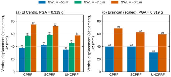
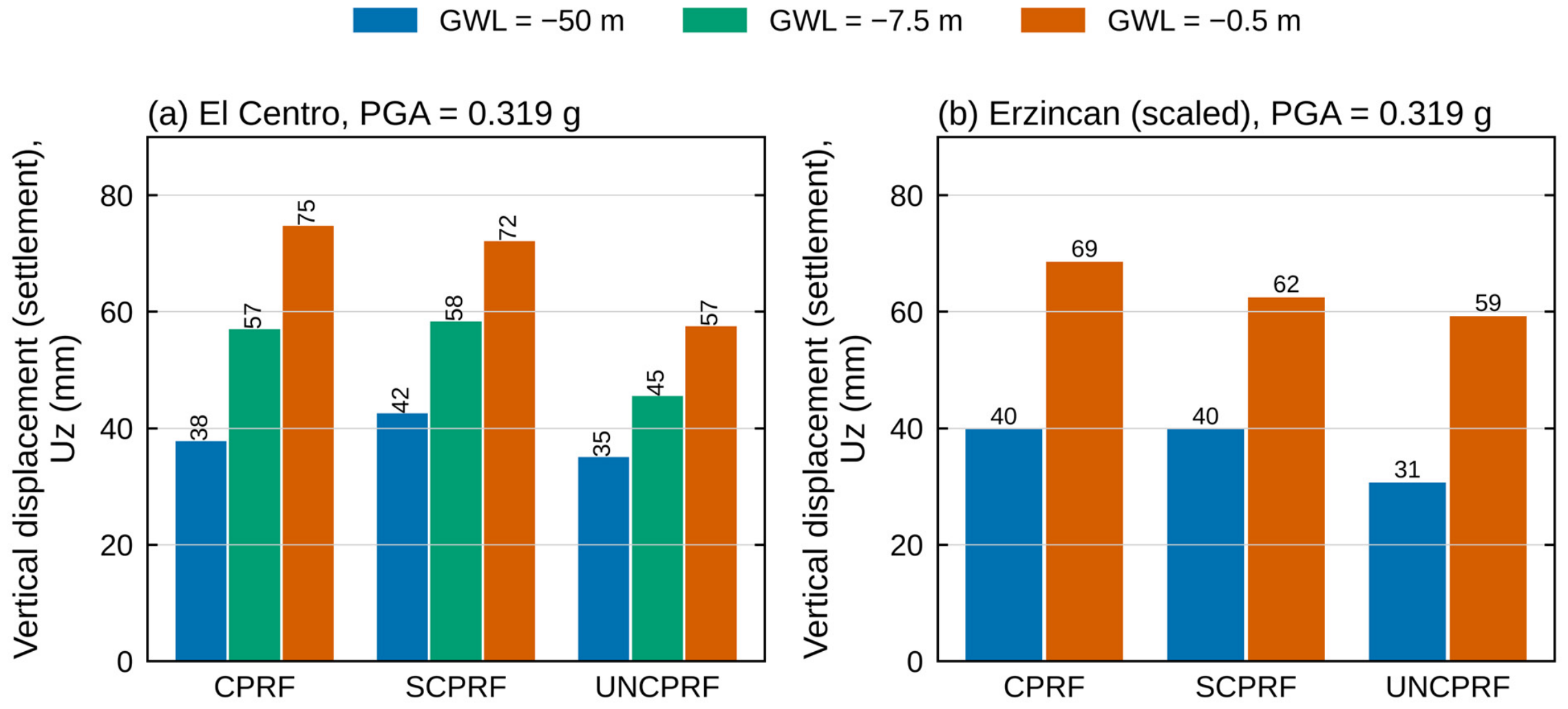
As the water table level increased, the seismic vertical settlement increased consistently across all three connection conditions under both records (Figure 21). At GWL = −0.5 m, settlement is 1.6–2.0 times that of the dry condition, and under El Centro it increases progressively with water level, reaching intermediate values at −7.5 m. The largest increase occurs in the CPRF under El Centro (about twice the dry value) and in the UNCPRF under ER-0.319 (about 1.9 times), so no system is systematically more sensitive to the water table; sensitivity depends on the record. Since the Hardening Soil (HS) model was applied under drained conditions, excess pore pressure is not generated, and the increase in settlement under saturated conditions is therefore not due to pore-pressure build-up. It is consistent with the reduction in effective stress (γ′ ≈ 9.3 kN/m3 below the water table against γunsat ≈ 15.2 kN/m3 above it), since in the HS model the stiffness of the sand depends on the stress level, so that a lower mean effective stress reduces the stiffness and, with it, the resistance of the soil beneath the raft [13]. Under saturated conditions, the UNCPRF still shows the lowest settlement under both records, so the cushion arrangement’s benefit is not lost with the water table.
Figure 21.
Effect of groundwater level GWL on vertical displacement (Uz) at the center of the raft surface for the systems: (a) EL Centro record, PGA = 0.319 g, (b) Erzincan record, PGA = 0.319 g.
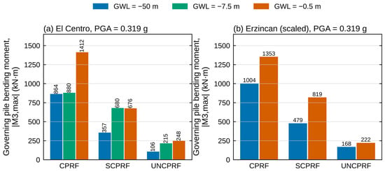
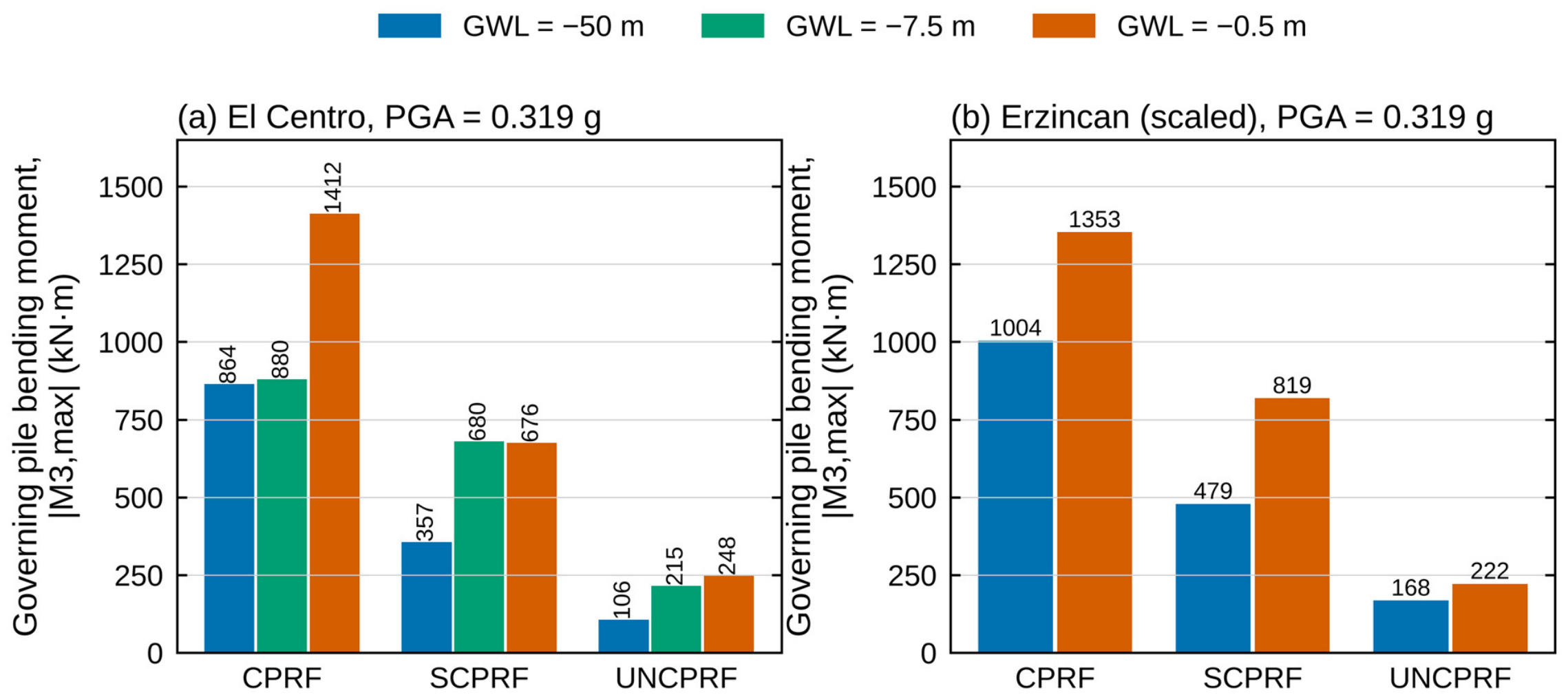
The governing pile moment of the three systems under both records (Figure 22) increases as the water table rises. The bending moment is taken as the maximum absolute moment along the pile with the largest value (the middle pile for the CPRF and SCPRF and the edge pile for the UNCPRF). The effect is largest in the CPRF, whose middle pile reaches 1412 and 1353 kN·m under El Centro and ER-0.319 (increases of 63% and 35%), making this the governing bending moment demand across the entire dataset. followed by the SCPRF (increases of about 90% and 70%) and, in absolute terms, the UNCPRF, whose moments remain below 250 kN·m, and the GWL influence is secondary to the dominant effect of the free-head condition, which limits the magnitude of moment demand regardless of soil saturation level. The system ranking is the same as in the dry condition, with the connected systems most affected.
Figure 22.
Effect of the groundwater level on the governing pile bending moment for the systems: (a) EL Centro record, PGA = 0.319 g, (b) Erzincan record scaled, PGA = 0.319 g.
Table 7 summarizes the effect of groundwater level on the peak response of the three piled systems under El Centro and Erzincan scaled to the same PGA of 0.319 g. The table shows the peak horizontal displacement of the raft, peak settlement, and governing pile moment at each water level, along with the change relative to the dry condition (GWL = −50 m).
Table 7.
Effect of the groundwater level on the peak response of the piled systems under El Centro (PGA = 0.319 g) and Erzincan scaled to 0.319 g (ER-0.319).
6. Conclusions and Limitations
The study performed three-dimensional finite element analyses (PLAXIS 3D V20) to examine how pile-head connection conditions and groundwater level affect the seismic response of piled-raft foundations under the El Centro and Erzincan records, with the latter at its original intensity and scaled to El Centro’s PGA. Within the investigated conditions (medium-dense sand, a 4 × 4 group of 15 m piles beneath a 15.4 m raft, two input motions, and drained, non-liquefaction conditions), the following conclusions are drawn:
- In the analyses performed, the CPRF gave the lowest peak absolute displacement under El Centro and the scaled Erzincan record (15.6% and 12.8% below the RF), whereas this reduction decreased to 4.5% under the original Erzincan record. The UNCPRF did not reduce the absolute displacement (by at most 1.2%), but gave the lowest displacement relative to the soil base under all three motions (about 22% below the RF).
- In the cases analyzed, the UNCPRF gave the lowest settlement under all motions. The reduction in settlement provided by the piles relative to the RF increased with the intensity of shaking, since the settlement of the RF increased more than that of the piled systems.
- The CPRF and SCPRF amplified the peak raft acceleration to about 5–6 times the soil-base value under El Centro and the original Erzincan record, against 1.5–2.0 times for the RF and UNCPRF.
- The maximum pile moment occurred at the pile head in the CPRF (up to 1004 kN·m in the dry condition), at depth in the SCPRF, and in the mid-to-lower shaft in the UNCPRF, which developed the smallest moments (below 250 kN·m) in all cases analyzed. The moments did not scale with PGA alone, suggesting dependence on the motion’s frequency content and duration.
- In the drained analyses, raising the water table to −0.5 m increased the settlement by a factor of 1.6–2.0 and the governing pile moment of the CPRF by 35–63%, consistent with the reduction in effective stress. The lower absolute displacement of the CPRF with a shallow water table did not correspond to a smaller lateral deformation, since the displacement relative to the soil base increased by 20–55% under the Erzincan record.
- For several responses, the benefit of each system relative to the RF depended on the record, so that, for the configuration studied, the performance of a connection condition cannot be inferred from a single motion.
Therefore, the conclusions cannot be generalized to other soil profiles, pile arrangements, connection details, or liquefiable conditions without further analyses.
Limitations
The conclusions hold for conditions without liquefaction, since the Hardening Soil model under drained conditions does not capture pore-pressure build-up. They refer to two records and a single configuration (medium-dense sand, a 4 × 4 pile group with fixed pile spacing and length, a single raft thickness, and a single applied load), and they represent the pile-head connection only with fixed and hinged idealizations. Extending the study with cyclic constitutive models, a larger set of ground motions, other foundation configurations (pile spacing and length, raft thickness), and other soil profiles, including cohesive soils, would be valuable.
Author Contributions
Conceptualization, H.H.A.-D. and S.Ç.; methodology, H.H.A.-D.; software, H.H.A.-D.; validation, H.H.A.-D.; formal analysis, H.H.A.-D.; investigation, H.H.A.-D.; data curation, H.H.A.-D.; writing—original draft preparation, H.H.A.-D.; writing—review and editing, S.Ç.; visualization, H.H.A.-D.; supervision, S.Ç. All authors have read and agreed to the published version of the manuscript.
Funding
This research received no external funding.
Institutional Review Board Statement
Not applicable.
Informed Consent Statement
Not applicable.
Data Availability Statement
The original contributions presented in this study are included in the article. Further inquiries can be directed to the corresponding author.
Conflicts of Interest
The authors declare no conflicts of interest.
References
- Randolph, M.F. Design methods for pile groups and piled rafts. In Proceedings of the 13th International Conference on Soil Mechanics and Foundation Engineering, New Delhi, India, 5–10 January 1994; Volume 5, pp. 61–82. [Google Scholar]
- Chanda, D.; Saha, R.; Haldar, S.; Choudhury, D. State-of-the-art review on responses of combined piled raft foundation subjected to seismic loads using static and dynamic approaches. Soil Dyn. Earthq. Eng. 2023, 169, 107869. [Google Scholar] [CrossRef] [Scilit]
- Tankara, S.; Biswas, S.; Halder, P.; Roy, S. A comprehensive review on the dynamic behaviour of connected and nonconnected pile-raft foundations. J. Earthq. Eng. 2025, 29, 865–900. [Google Scholar] [CrossRef] [Scilit]
- Chaudhuri, C.H.; Chanda, D.; Saha, R.; Haldar, S. Three-dimensional numerical analysis on seismic behavior of soil-piled raft-structure system. Structures 2020, 28, 905–922. [Google Scholar] [CrossRef] [Scilit]
- Matsumoto, T.; Nemoto, H.; Mikami, H.; Yaegashi, K.; Arai, T.; Kitiyodom, P. Load tests of piled raft models with different pile head connection conditions and their analyses. Soils Found. 2010, 50, 63–81. [Google Scholar] [CrossRef] [Scilit]
- Saeedi Azizkandi, A.; Baziar, M.H.; Fatahi Yeznabad, A. 3D dynamic finite element analyses and 1 g shaking table tests on seismic performance of connected and nonconnected piled raft foundations. KSCE J. Civ. Eng. 2018, 22, 1750–1762. [Google Scholar] [CrossRef] [Scilit]
- Saadatinezhad, M.; Lakirouhani, A.; Jabini Asli, S. Seismic response of non-connected piled raft foundations. Int. J. Geotech. Eng. 2021, 15, 66–80. [Google Scholar] [CrossRef] [Scilit]
- Halder, P.; Manna, B.; Sur, A. Impact of Pile Head Rigidity on the Response of Piled Raft in Sand Under Pseudo-Static Loading. Indian Geotech. J. 2020, 50, 810–824. [Google Scholar] [CrossRef] [Scilit]
- Seed, H.B.; Idriss, I.M. Simplified procedure for evaluating soil liquefaction potential. J. Soil Mech. Found. Div. 1971, 97, 1249–1273. [Google Scholar] [CrossRef] [Scilit]
- Gao, G.-Y.; Xie, W.; Song, J.; Wang, Y. Prediction of seismic compression of saturated sand considering the ground motion characteristics and variable permeability. Soil Dyn. Earthq. Eng. 2020, 130, 105971. [Google Scholar] [CrossRef] [Scilit]
- Meena, N.K.; Nimbalkar, S. Effect of water drawdown and dynamic loads on piled raft: Two-dimensional finite element approach. Infrastructures 2019, 4, 75. [Google Scholar] [CrossRef] [Scilit]
- Poulos, H.G. Piled raft foundations: Design and applications. Géotechnique 2001, 51, 95–113. [Google Scholar] [CrossRef] [Scilit]
- Schanz, T.; Vermeer, P.A.; Bonnier, P.G. The hardening soil model: Formulation and verification. In Beyond 2000 in Computational Geotechnics: Ten Years of PLAXIS International; Brinkgreve, R.B.J., Ed.; Balkema: Rotterdam, The Netherlands, 1999; pp. 281–296. [Google Scholar]
- Kumar, A.; Choudhury, D.; Katzenbach, R. Behaviour of combined pile-raft foundation (CPRF) under static and pseudo-static conditions using PLAXIS3D. In Proceedings of the 6th International Conference on Earthquake Geotechnical Engineering (6ICEGE), Christchurch, New Zealand, 1–4 November 2015. Paper ID 140. [Google Scholar]
- Singh, S.; Solanki, C.H.; Shukla, S.J. A finite element analysis on the performance and load sharing mechanism of unconnected piled raft foundation on cohesive soil. Indian Geotech. J. 2026, 56, 575–597. [Google Scholar] [CrossRef] [Scilit]
- Xue, H.; Zhang, J.; Xu, J.; Zhang, X.; Tian, B. Seismic response of disconnected piled raft foundations: Effects of cushion layer types based on shaking table tests. Soil Dyn. Earthq. Eng. 2026, 200, 109863. [Google Scholar] [CrossRef] [Scilit]
- Malekkhani, M.J.; Bolouri Bazaz, J. An analytical model to study the behavior of non-connected piled rafts with granular cushion subjected to vertical load. Int. J. Civ. Eng. 2021, 19, 941–956. [Google Scholar] [CrossRef] [Scilit]
- El Kamash, W.; El Naggar, H.; Nabil, M.; Ata, A. Optimizing the unconnected piled raft foundation for soft clay soils: Numerical study. KSCE J. Civ. Eng. 2020, 24, 1095–1102. [Google Scholar] [CrossRef] [Scilit]
- Zhu, X. Analysis of the load sharing behaviour and cushion failure mode for a disconnected piled raft. Adv. Mater. Sci. Eng. 2017, 2017, 3856864. [Google Scholar] [CrossRef] [Scilit]
- Meyerhof, G.G. Bearing capacity and settlement of pile foundations. J. Geotech. Eng. Div. 1976, 102, 197–228. [Google Scholar] [CrossRef] [Scilit]
- Silver, M.L.; Seed, H.B. Volume changes in sands during cyclic loading. J. Soil Mech. Found. Div. 1971, 97, 1171–1182. [Google Scholar] [CrossRef] [Scilit]
- Tokimatsu, K.; Seed, H.B. Evaluation of settlements in sands due to earthquake shaking. J. Geotech. Eng. 1987, 113, 861–878. [Google Scholar] [CrossRef] [Scilit]
- Nikolaou, S.; Mylonakis, G.; Gazetas, G.; Tazoh, T. Kinematic pile bending during earthquakes: Analysis and field measurements. Géotechnique 2001, 51, 425–440. [Google Scholar] [CrossRef]

Disclaimer/Publisher’s Note: The statements, opinions and data contained in all publications are solely those of the individual author(s) and contributor(s) and not of MDPI and/or the editor(s). MDPI and/or the editor(s) disclaim responsibility for any injury to people or property resulting from any ideas, methods, instructions or products referred to in the content. |
© 2026 by the authors. Licensee MDPI, Basel, Switzerland. This article is an open access article distributed under the terms and conditions of the Creative Commons Attribution (CC BY) license.