


Abstract
Geometric and laminate modifications can increase bending-induced twists in wind turbine blade spars, but the associated changes in deformation, stress, mass, and vibration are not always assessed on a consistent basis. This study therefore compares the structural trade-offs of four established design parameters under a common finite-element framework. An equivalent thin-walled composite box-spar model based on the NREL 5 MW reference blade was developed using a midsurface representation with spanwise-varying cross-sections, zoned layups, and thickness tapering. Spar-cap thickness, shear-web inclination angle, spar-cap off-axis ply angle, and off-axis ply fraction were varied individually under consistent loading and boundary conditions. The results show that spar-cap thickness primarily influences flapwise deflection and structural mass. Shear-web inclination produces the largest twist-to-deflection response index, reaching approximately 1.17–1.21 °/m at ±20°, but also increases tip deflection and peak equivalent stress. Increasing the off-axis ply angle or fraction does not improve this response for the investigated layups. For the C2 configuration, the response index decreases to approximately 22% of the baseline value, accompanied by increased deflection and stress and reduced natural frequencies. These findings reveal parameter-dependent structural trade-offs under the prescribed model and loading conditions, providing a comparative basis for further blade-spar design and validation.
1. Introduction
Wind power has become an important part of the global renewable energy sector due to its distinct advantages. According to the Global Wind Report 2026 released by the Global Wind Energy Council (GWEC), 165 GW of new wind power capacity was installed worldwide in 2025, representing the a 40% increase over the previous record set in 2024. The global wind power industry continues to expand rapidly [1]. As wind turbine capacity increases, blades become larger, lighter, and more flexible [2,3]. Fiber-reinforced composites are widely used in large wind turbine blades because of their high specific strength and stiffness [3]. The main spar is the primary load-bearing structure of a wind turbine blade. It carries the main bending loads and governs the bending, torsional, and bend–twist coupling stiffness of the blade section. Changes in its geometry and layup therefore directly affect the blade’s bending, torsional, and coupled responses. Accordingly, clarifying the effects of main spar parameters on bending and torsional responses is important for the structural design and passive load alleviation of large flexible blades.
Bend–twist coupling refers to the simultaneous bending and torsional deformation of a blade under bending loads. It can be achieved through material coupling by exploiting composite anisotropy or through geometric coupling using structural features such as sweep and pre-bend [4,5]. In addition, adjusting the internal web position can also induce a bend–twist response, which is referred to as structural coupling [6]. In recent years, research has gradually shifted from bend–twist coupling mechanisms to passive load alleviation. Zhao et al. [7] investigated the load alleviation of large flexible blades by varying the fiber misalignment angle in the main spar and the onset location of coupling. Serafeim et al. [8] applied material coupling through rotation of the spar-cap laminates to the lightweight design of a 10 MW wind turbine blade. These studies showed that both geometric and material modifications can alter the bend–twist response, although their effects on structural performance differ.
For the structural and dynamic behavior of bend–twist coupled blades, Chen et al. [9] investigated the effects of cross-sectional stiffness parameters on aeroelastic responses using a 6 × 6 sectional stiffness matrix. Shakya et al. [10] examined the effects of laminate imbalance and fiber orientation on the flutter characteristics of composite blades. Ma et al. [11] further investigated the effects of blade pre-bend and sweep on aeroelastic loads. Regarding the internal configuration of the main spar, Wang et al. [12,13,14] studied the effects of double-web configurations, web offset, and composite layups on the bend–twist response, stress distribution, and buckling behavior of large blades. Their results revealed a clear interaction between web offset and layup configuration.
In composite layup and structural optimization, Dong et al. [15] developed a multi-objective optimization method for layup parameters. Fu et al. [16] experimentally investigated the effects of fiber orientation and hybrid ratio on the equivalent bend–twist coupling coefficient of carbon/glass hybrid composite blades. Li et al. [17] quantified the effects of main spar parameters on the sectional stiffness matrix and aeroelastic stability. Kou et al. [18] optimized the layup ratio and sequence of the spar cap for a 5 MW blade based on classical laminate theory. Tang et al. [19] further examined the relationship between layup parameters and flutter characteristics under multiple operating conditions. Hermansen and Lund [20] performed coupled material–thickness optimization, while Wu et al. [21] incorporated structural mass and reliability-related metrics into the multi-objective design of large flexible blades. In addition, Jang et al. [22] and Kim and Kang [23] investigated composite blade safety from the perspectives of progressive failure and fatigue crack propagation, respectively. He et al. [24] and Jeong and Park [25] further integrated aerodynamic, structural, and safety performance into multidisciplinary design. From the perspective of structural condition assessment, Civera and Surace [26] reviewed non-destructive inspection and structural health monitoring methods for wind turbines and summarized the general requirements for structural integrity evaluation. Although their work focuses on monitoring rather than bend–twist design, it provides relevant context for interpreting structural response indicators and considering their validation under practical operating conditions.
Previous studies have shown that spar geometry and composite layup can affect the bending, torsional, and dynamic responses of wind turbine blades. Several studies have also examined the combined effects of shear-web configuration and composite layup or performed structural and laminate optimization. However, differences in reference models, loading assumptions, and evaluation metrics hinder direct comparison of the relative effects of these design parameters and their associated performance trade-offs. A larger bending-induced twist does not necessarily indicate better overall structural performance, because it may be accompanied by increased deformation and stress or unfavorable changes in natural frequencies. A consistent comparative framework is therefore needed to distinguish parameter-dependent response characteristics and associated performance penalties under identical modeling and loading conditions.
To provide such a comparison, this study develops a parametric finite element model of the NREL 5 MW wind turbine blade main spar using a thin-walled composite midsurface representation with spanwise-varying cross-sections and zoned layups. Four design variables are investigated: spar-cap thickness, shear-web inclination angle, spar-cap ply angle, and off-axis ply content. Their effects on tip displacement, bending-induced twist, maximum equivalent stress, the first three natural frequencies, and structural mass are evaluated under consistent loading and boundary conditions. The comparison combines the direct response values, a range-normalized influence index, and a load-specific twist-to-deflection response index. The main contribution lies in identifying parameter-specific response characteristics and structural trade-offs within a common numerical framework, rather than proposing a new finite element or optimization methodology. Attention is given to the directional twist response induced by shear-web inclination, the mass penalty associated with increasing spar-cap thickness, and the stiffness and stress penalties caused by off-axis plies. The findings are limited to the parameter ranges investigated and prescribed loading conditions.
2. Materials and Methods
2.1. Reference Wind Turbine and Blade Spar Model
This study uses the blade of the NREL 5 MW reference wind turbine as the reference configuration [27,28]. The blade has a length of 61.5 m and the hub diameter is 3 m. The rotor diameter is 126 m, equal to twice the blade length plus the hub diameter. Table 1 summarizes the principal specifications of the reference wind turbine used in the present study.
Table 1.
Main specifications of the NREL 5 MW reference wind turbine.
2.1.1. Geometric Reference Model of the Blade Spar
Detailed information on the spar-cap width, web position, local layup, and thickness distribution is not provided in the public NREL 5 MW blade data. Therefore, an equivalent box-spar model was developed using the published spanwise chord distribution and airfoil geometry. The model includes the upper and lower spar caps and the front and rear shear webs, but excludes the complete aerodynamic shell, leading- and trailing-edge structures, and other full-blade components. Nine control stations were selected within 0.05 L–0.95 L to describe the spanwise variation in the spar geometry.
The chordwise width of the spar box was defined as a fraction of the local blade chord:
where bs(z) is the chordwise width of the spar box, (cz) is the local blade chord, and λb is the dimensionless relative spar-width coefficient. The baseline value of λb = 0.2 was adopted to define a consistent reference geometry for the subsequent parametric analysis.
bs(z) = λbc(z)
The spar-box height was estimated from the local maximum airfoil thickness:
where hs(z) is the spar-box height (m), trel(z) is the dimensionless relative airfoil thickness,(cz) is the local blade chord (m), and λh is the dimensionless spar-height coefficient. The baseline value of λh = 0.7 was adopted to keep the equivalent spar box within the local airfoil envelope.
hs(z) = λhtrel(z)c(z)
Table 2 lists the spanwise coordinates and calculated principal geometric dimensions of the nine control stations. The stations are located at x/L = 0.05, 0.10, 0.20, 0.30, 0.40, 0.50, 0.65, 0.80, and 0.95. Here, x denotes the spanwise distance measured from the blade root, and L = 61.5 m is the blade length. S1 and S9 are interior reference stations rather than the physical root and tip of the complete blade.
Table 2.
Spanwise control-station coordinates and principal geometric dimensions of the baseline equivalent box spar.
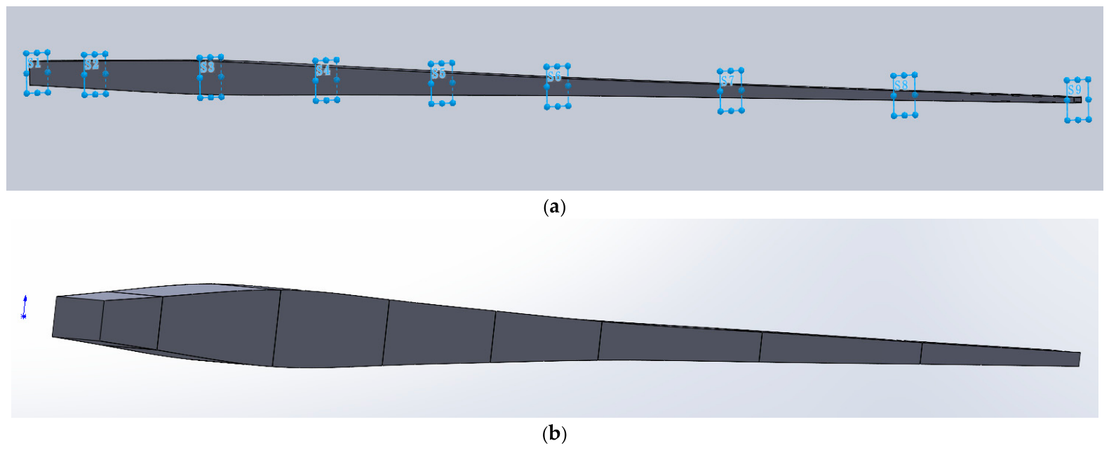
Figure 1 presents the parametric blade-spar model used in this study. Figure 1a shows the nine spanwise control stations (S1–S9) and the variable cross-sectional geometry.
Figure 1.
Parametric modeling of the wind turbine blade spar: (a) geometric reference model and spanwise control stations; (b) thin-walled midsurface finite-element model.
2.1.2. Thin-Walled Midsurface Model of the Blade Spar
Based on the geometric reference model, the midsurfaces of the upper and lower spar caps and the front and rear shear webs were extracted while preserving the locations, widths, and heights of the control sections. These surfaces were used as the reference geometry for the composite shell elements, as shown in Figure 1b. The physical thickness of the spar caps and shear webs were subsequently defined in ANSYS (2022R1) ACP according to the material type, ply orientation, and number of plies.
This midsurface representation reduces the computational cost associated with layerwise solid modeling and avoids excessively high-aspect-ratio elements. At the same time, it preserves the key laminate and geometric features that govern the global bending and torsional responses of the blade spar. These features include region-wise laminate definitions, spanwise ply drop-offs, fiber orientations, and the dual-web configuration.
The equivalent box-spar midsurface model was discretized with four-node SHELL181 elements in ANSYS Mechanical. Laminate thicknesses, stacking sequences, and material orientations were defined in ANSYS ACP. For the selected M3 mesh, a global element size of 50 mm was used, with local refinement to 10 mm in the root region.
2.2. Composite Material System and Baseline Laminate Configuration
To provide sufficient spanwise bending stiffness while maintaining shear load-carrying capability, this study adopts a composite material system consistent with established large wind turbine blade spar designs. The laminate model was implemented in ANSYS Composite PrepPost (ACP), where the local material orientations, stacking sequences, and laminate regions were defined [25]. The upper and lower spar caps were modeled using M1 unidirectional carbon-fiber-reinforced polymer (CFRP), whose high longitudinal modulus provides the primary spanwise tensile and compressive load-carrying capability. The front and rear shear webs were modeled using M2 biaxial glass-fiber-reinforced polymer (GFRP) to provide in-plane shear resistance, torsional support, and overall stability of the box spar. Each material was defined in ACP using homogenized cured-ply properties. The NREL 5-MW reference report provides the reference turbine and blade structural context but does not specify the resin formulation of the equivalent composite materials adopted here. Accordingly, the present model does not identify a specific resin grade or model the reinforcing fibers and polymer matrix as separate constituents. The fiber volume fraction was not specified as an independent input parameter in the present model. Accordingly, the numerical results characterize the responses of the adopted equivalent composite material systems rather than experimentally measured behavior of manufactured blade-spar specimens. Table 3 summarizes the mechanical properties and baseline laminate definitions adopted in the model.
Table 3.
Mechanical properties and baseline laminate definitions of the composite materials used in the blade spar.
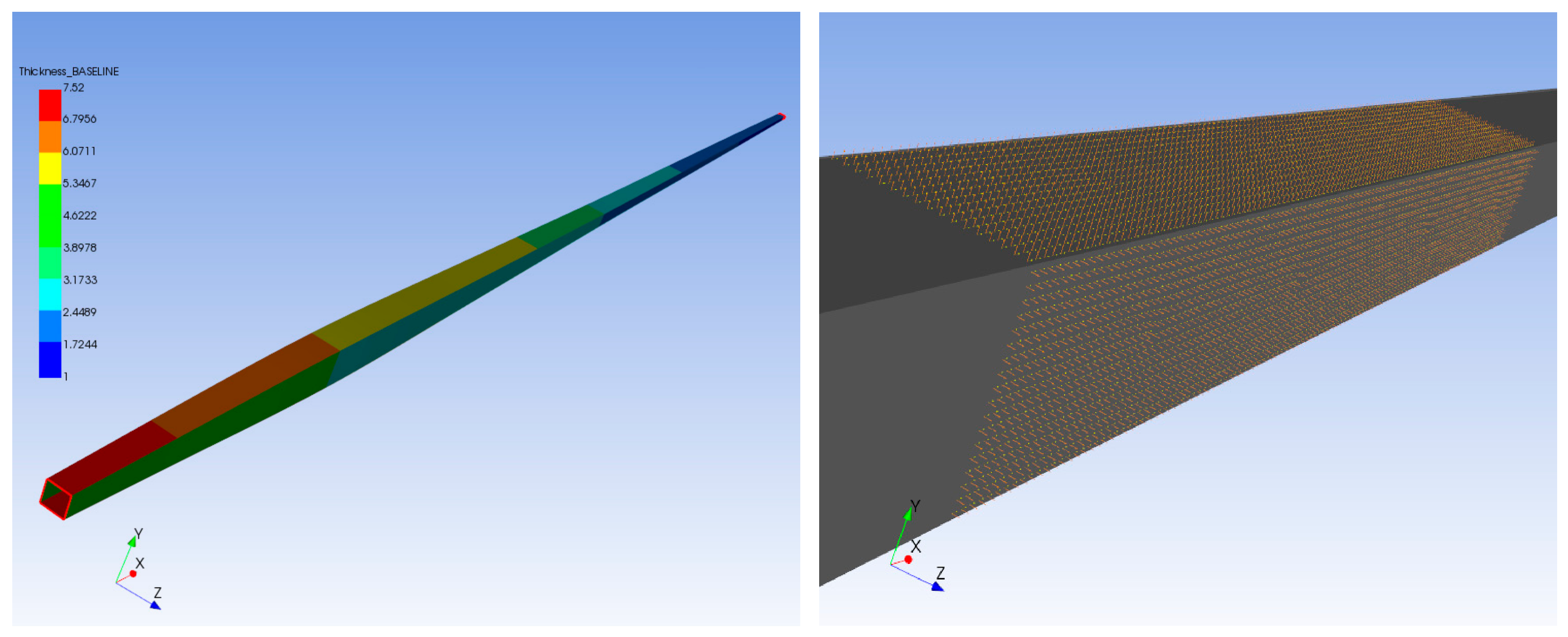
For the laminate orientation, the local spanwise direction of the blade spar was defined as the 0° reference direction for the spar caps. The upper and lower spar caps in the baseline model used 0° plies as the primary load-carrying layers. Region-wise ply drop-offs were introduced along the span to reproduce the prescribed thickness variation in the baseline spar. The front and rear shear webs were modeled using the M2 biaxial GFRP fabric. In ACP, the Modeling Ply angle for the web laminates was set to 0°, which aligns the local material coordinate system of the fabric with the reference direction of the shear web. This setting does not imply that all constituent fiber directions in the web are oriented at 0°. The all 0° spar-cap layup was adopted as the baseline configuration because the spar caps primarily carry spanwise tensile and compressive loads induced by flapwise bending. This baseline configuration provides a consistent reference for evaluating the effects of off-axis reinforcement; it is not intended to represent an optimal layup for every loading condition. To investigate the influence of off-axis plies, spar-cap ply angles of ±30°, ±45°, and ±60°, together with different ±45° ply fractions, were examined in the subsequent parametric analyses.
At the laminate level, classical laminate theory distinguishes between stiffness and coupling terms. For balanced laminates, the extension–shear coupling terms A16 and A26 vanish. For symmetric laminates, the extension–bending coupling matrix B is zero. However, the bending–twisting coupling terms D16 and D26 may remain nonzero, depending on the through-thickness ply arrangement. Therefore, changes in the global bending-induced twist response of the equivalent box-spar model do not necessarily indicate changes in intrinsic laminate-level coupling stiffness.
Figure 2 illustrates the baseline laminate regions and local material orientations adopted for the blade spar.
Figure 2.
Baseline laminate regions and local material orientations of the blade spar.
Table 4 summarizes the active ply counts and corresponding nominal laminate thicknesses of the upper and lower spar caps and the front and rear shear webs at each spanwise control station S1–S9.
Table 4.
Ply counts and nominal laminate thicknesses at the nine spanwise control stations.
2.3. Design Variables and Response Metrics
To compare the effects of different blade-spar design parameters under consistent modeling, loading, and boundary conditions, the thin-walled midsurface model was adopted as the baseline model. Four design variables were considered: spar-cap thickness, shear-web inclination angle, spar-cap off-axis ply angle, and off-axis ply fraction. These variables represent different structural tailoring mechanisms, namely sectional bending-stiffness control, geometric bend–twist coupling, and composite anisotropy tailoring. A single-factor-at-a-time approach was used for parametric analysis. When one design variable was varied, all other non-target parameters, including the remaining geometric and laminate parameters, material system, loads, and boundary conditions, were kept unchanged. This approach allows the effect of each design variable to be examined under consistent baseline conditions. However, it does not account for interaction effects among spar-cap thickness, shear-web inclination, and laminate configuration. Therefore, the reported response trends are specific to the selected baseline configuration and the investigated parameter ranges. Table 5 summarizes the investigated design variables and parameter levels.
Table 5.
Design variables and investigated parameter levels of the blade spar.
To quantify the effects of the design variables on the static, dynamic, and bend–twist responses of the blade spar, the following response quantities were evaluated: flapwise tip deflection (wtip), tip twist angle (θtip), maximum equivalent stress in the root evaluation region (σroot), the first three natural frequencies (f1, f2 and f3), and structural mass (M). To quantify the global twist induced by flapwise bending, this study adopts a bend–twist response measure based on established evaluation approaches [29]. The bend–twist response index, KBT, is defined as:
where wtip is the flapwise tip displacement magnitude at S9 in meters and θtip is the corresponding signed twist angle in degrees. In ANSYS Mechanical, θtip was obtained from the X-axis component of the Flexible Rotation result at RP-Tip-Center. Positive rotation follows the right-hand rule about the positive (X) axis. Accordingly, KBT (°/m) represents the magnitude of load-induced twist per unit flapwise displacement. It is used as a global comparative response index rather than a measure of intrinsic sectional bend–twist coupling stiffness. Since the computed rotation was not decomposed into contributions from structural deformation, laminate anisotropy, and load eccentricity, its sign is considered separately only to distinguish the rotation direction. Without defined aerodynamic inflow and blade-pitch references, the rotation cannot be classified as twist-to-feather or twist-to-stall.
To enable a consistent cross-comparison of the four design variables, a relative influence metric was further introduced. Because the response quantities have different units and numerical ranges, their raw variations cannot be compared directly. The baseline response was therefore used as a common reference. For each design variable p and response quantity j, the maximum absolute deviation from the baseline is defined as:
where p denotes the investigated parameter level, Rp,k,j is the value of response j for design variable p at level k, and R0,j is the corresponding baseline response.Ap,j therefore represents the maximum variation in response j induced by parameter p within the investigated range.
To compare the relative effects of different design variables on the same response quantity, Ap,j was normalized as:
where 0 ≤ Sp,j ≤ 1 A value of Sp,j = 1 indicates that the corresponding design variable produces the largest variation in response j among the variables considered. The index reflects only the relative influence within the prescribed parameter ranges and should not be interpreted as a global or probabilistic sensitivity measure.
2.4. Baseline Analysis Cases and Verification Metrics
To establish a consistent numerical basis for the subsequent parametric analysis, the reference model was examined through static and free-vibration modal analyses. The material layup and root constraint were kept unchanged in all verification cases. The S1 section of the main spar was fully fixed. As defined in Section 2.1.1, the fixed support was applied at S1 through the named selection Root-edge. In the static analysis, the load was applied through a remote point located at the center of the S9 section to reduce local stress concentrations caused by direct point loading. In the user-defined Blade Coordinate System, the transverse load was applied along the positive (Y) (flapwise) direction, corresponding to force components of (0, 1000, 0) N. The deformable coupling allowed deformation of the scoped edge during load transfer. The blade-tip flapwise displacement wtip, blade-tip torsion angle θtip, maximum stress, and root reaction force were extracted as the static response metrics. The stress metric was obtained as the maximum averaged equivalent stress on the top surface of the selected ply in the CAP_01 region. This quantity was used to compare the relative stress responses among the investigated configurations and was not treated as a ply-level failure index or a direct measure of composite strength.
The blade-tip torsion angle θtip represents the torsional response induced by transverse bending loads. This response reflects the combined effects of sectional geometric asymmetry and composite anisotropy and is therefore interpreted as load-induced bend–twist coupling, rather than the response to an independently applied pure torsional moment. The geometric center of the S9 section may not coincide with its shear center. Therefore, load eccentricity may contribute to the computed twist response. Since this effect was not quantified separately, the twist angle is treated as a comparative load-induced response rather than a direct measure of intrinsic bend–twist coupling.
Free-vibration modal analysis was performed using the same root constraint without external loading. The first three natural frequencies and their corresponding mode shapes were extracted. Therefore, the torsional response considered in this study represents load-induced bend–twist coupling rather than the response to pure torsional loading. Table 6 summarizes the baseline static and free-vibration analyses, including the prescribed conditions, extracted responses, and their use in subsequent parametric comparisons. The quantities listed in this section are used only to verify the reference model.
Table 6.
Baseline analysis cases and response measures for the equivalent box-spar model.
2.5. Mesh Convergence Analysis
To evaluate the effect of finite element discretization on the static and dynamic responses of the blade spar, a mesh strategy combining global mesh control with local root refinement was adopted. The geometry, material layup, boundary conditions, loading, and element type were kept unchanged. Three shell-element meshes were generated with global element sizes of 100, 70, and 50 mm and corresponding root-refinement sizes of 20, 14, and 10 mm. These meshes were used to assess the mesh convergence of the baseline model. Table 7 summarizes the three mesh configurations and the corresponding structural responses.
Table 7.
Mesh configurations and corresponding key structural responses.
Using the M3 solution as the reference, the relative difference between the M2 and M3 results was calculated as:
where RM2 and RM3 denote the corresponding structural responses obtained with the M2 and M3 meshes, respectively.
The relative differences between M2 and M3 are 0.122% for the flapwise tip deflection and 0.637% for the tip twist angle. For the first three natural frequencies, the corresponding differences are 0.0166%, 0.0368%, and 0.0101%, respectively. All values are well below 5%. For the selected-ply stress metric defined in Section 2.4, the maximum averaged equivalent stress in the root evaluation region increased from 37.813 MPa for M2 to 39.418 MPa for M3. The relative difference was 4.072%, indicating greater mesh sensitivity in the local stress response than in global displacement and low-order modal responses. M3 was therefore retained for subsequent comparative analyses. However, mesh convergence alone does not validate composite failure predictions or demonstrate insensitivity to the prescribed boundary conditions.
For a direct comparison of convergence trends among responses with different magnitudes, each response was normalized by the corresponding M3 result:
where R* is the normalized response and RM3 is the corresponding value obtained with the M3 mesh.
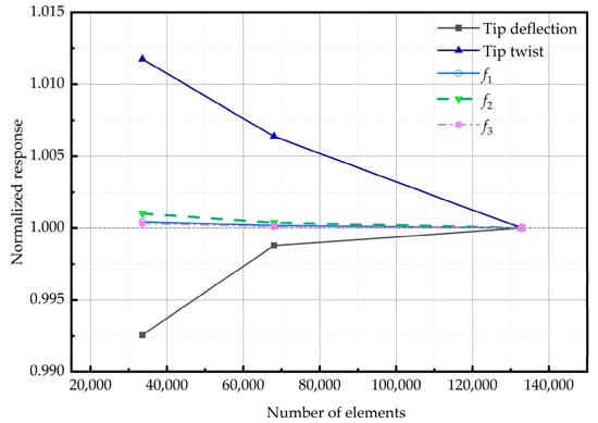
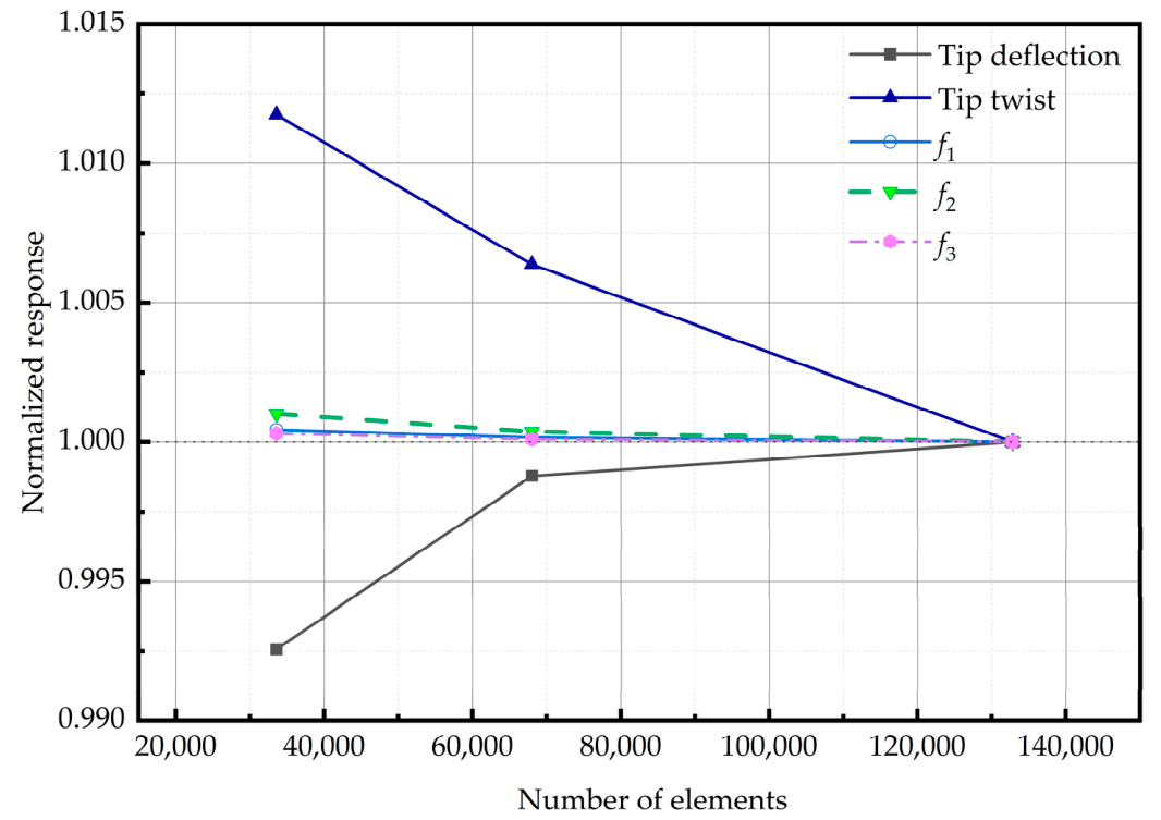
Figure 3 compares the normalized global responses obtained with the three mesh resolutions. All responses approach unity as the mesh is refined from M1 to M3, confirming satisfactory convergence of the global static and low-order dynamic responses. The flapwise tip deflection changes from 0.9926 to 1.0000, whereas the normalized tip twist approaches unity from 1.0118. The first three natural frequencies remain close to the M3 reference values for all three meshes. These results show that further mesh refinement has only a minor effect on the global stiffness and low-order dynamic characteristics of the spar. Accordingly, the M3 mesh was adopted for all subsequent static and modal analyses.
Figure 3.
Mesh-convergence behavior of the normalized key structural responses.
2.6. Model Applicability, Numerical Verification and Limitations
Mesh convergence demonstrates the numerical stability of the finite element discretization, but it does not constitute an external validation of the local structure of the prototype blade. The publicly available NREL 5 MW data provide the blade dimensions, chord distribution, and overall structural characteristics. However, they do not include the complete local geometry and laminate details required to reproduce the box-type blade spar considered in this study. Therefore, the present model is treated as an equivalent parametric model for investigating structural response trends rather than as a high-fidelity reproduction of the prototype blade.
Furthermore, the NREL 5 MW reference data describe the structural properties of the complete blade, whereas the present model represents only an equivalent internal box spar. The omitted aerodynamic shell, leading- and trailing-edge structures, and other full-blade components contribute to the overall mass distribution, stiffness, and inertial properties. Their exclusion may therefore affect the predicted natural frequencies, mode shapes, and bending-induced twist response. Consequently, the published full-blade data cannot serve as direct validation targets for the present equivalent box-spar model. Independent quantitative validation against a geometrically and materially comparable spar model, with matched sectional stiffness or modal data, is not currently available.
All subsequent parametric analyses were conducted using the same baseline model, the M3 mesh, and identical loading and boundary conditions. This consistent numerical framework reduces the influence of modeling assumptions on the relative comparison of the design variables. The model retains the main features governing the global bend–twist response, including the variable cross-section, region-wise ply drop-offs, fiber orientations, and dual-web geometry. It is therefore suitable for the comparative analysis of deflection, twist, low-order natural frequencies, and stress trends addressed in this study.
However, no publicly accessible experimental dataset sufficiently matching the local spar geometry, laminate configuration, material properties, boundary conditions, and loading conditions of the present model was identified for direct quantitative validation. Accordingly, the present model has not been experimentally validated, and its results should be interpreted as comparative numerical trends under the prescribed modeling assumptions and loading conditions, rather than as experimentally confirmed predictions for a specific manufactured blade. The prescribed 1000 N transverse force was used only as a comparative reference load and should not be interpreted as evidence of aerodynamic load alleviation under actual operating conditions. In addition, the present modal analysis was conducted using temperature-independent material properties, without accounting for environmental variability and its potential influence on the predicted natural frequencies.
Future work will focus on establishing a more comprehensive validation framework for the present equivalent box-spar model. First, a higher-fidelity reference model will be developed. This model will include more complete structural geometry and laminate information. It will allow systematic comparisons of spanwise mass distribution, sectional bending and torsional stiffness, and modal characteristics. Furthermore, suitable experimental datasets will be sought where available. Dedicated static bending, torsional, and modal tests may also be conducted where feasible. The predicted displacements, twist angles, strains, natural frequencies, and mode shapes will then be compared with measured responses. These efforts will help further evaluate the accuracy and applicability of the equivalent box-spar model. Future investigations will also consider temperature-dependent composite material properties and modal responses under varying environmental conditions to distinguish design-induced frequency changes from environmental effects.
3. Results
3.1. Effect of Spar-Cap Thickness
The baseline spar cap uses segmented spanwise thickness tapering. Because the reference ply count and equivalent thickness vary along the span, a single absolute thickness is not suitable as the design variable. Therefore, a dimensionless thickness scaling factor, kt, was introduced to uniformly scale the local reference thickness and was defined as:
where r denotes the spanwise position, tcap,0(r) is the local spar-cap thickness of the baseline model, and tcap(r) is the corresponding thickness for a given design case. Accordingly, kt = 1 represents the baseline configuration.
In ANSYS ACP, the scaling defined by kt was implemented by applying the same factor to the effective thickness of each spar-cap ply. The ply count, stacking sequence, material orientations, and material properties were kept unchanged. This treatment preserves the baseline laminate configuration and spanwise ply-drop pattern while allowing continuous thickness variation.
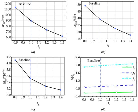
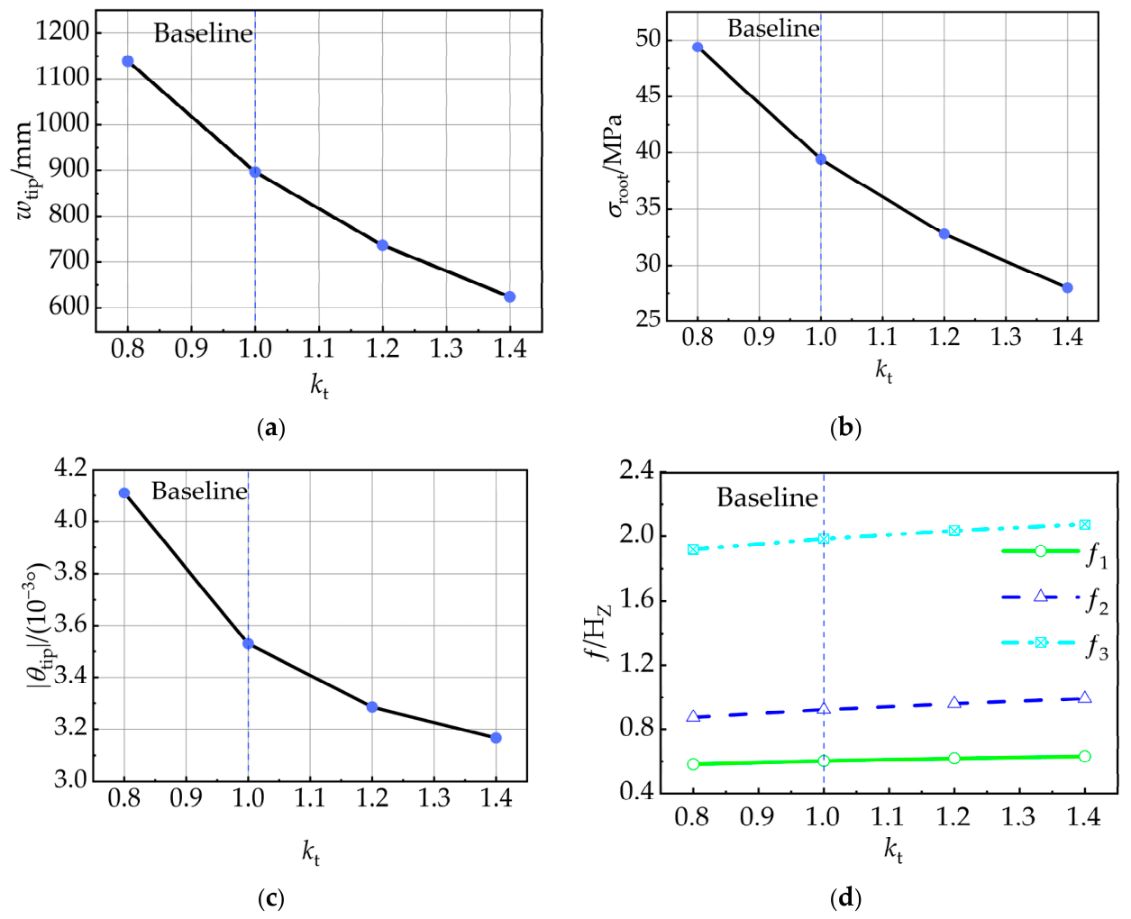
The effects of the spar-cap thickness scaling factor on the static, bend–twist, and modal responses are summarized in Figure 4.
Figure 4.
Effects of the spar-cap thickness scaling factor on structural responses: (a) flapwise tip deflection; (b) maximum equivalent stress; (c) tip twist angle; (d) first three natural frequencies.
Figure 4a,b show that increasing kt from 0.8 to 1.4 reduces the tip displacement from 1139.30 mm to 624.30 mm and the maximum stress from 49.381 MPa to 27.989 MPa. These changes correspond to reductions of 45.20% and 43.32%, respectively. Comparison between adjacent cases shows that the marginal reductions in both responses become smaller as spar-cap thickness increases, indicating diminishing improvement in static performance.
Figure 4c shows that its magnitude decreases from 0.004110° to 0.003166° as kt increases, corresponding to a reduction of 22.97%. This reduction is considerably smaller than that in tip displacement, indicating that spar-cap thickness primarily affects bending stiffness and has a weaker influence on the torsional response. Figure 4d shows that the first three natural frequencies increased from 0.58308, 0.87532, and 1.9180 Hz to 0.63098, 0.99227, and 2.0744 Hz, respectively. The corresponding increases are 8.21%, 13.36%, and 8.15%. The second natural frequency is the most sensitive to spar-cap thickness. Within the range investigated, the stiffness increase therefore has a greater effect on the low-order natural frequencies than the associated increase in structural mass.
Overall, spar-cap thickness primarily governs global stiffness. Its effects on tip displacement and maximum stress are stronger than those on tip twist angle and low-order natural frequencies. However, increasing kt from 1.0 to 1.4 raises the structural mass from 737.37 kg to 887.18 kg, an increase of 20.32%, while the improvement in static response gradually decreases. Spar-cap thickness should therefore be selected by balancing stiffness improvement against the associated mass penalty.
3.2. Effect of Shear-Web Inclination Angle
To evaluate the effect of main-spar cross-sectional geometry, the shear-web inclination angle, θw, was selected as the geometric variable. The midsurface position of the upper spar cap in the baseline box-shaped spar was kept fixed, while the lower spar cap was shifted chordwise at each control section. This produced equal inclination angles in the front and rear shear webs. The spar-cap width, spar-cap and shear-web thicknesses, material properties, layup configuration, and in-plane partitioning were kept unchanged. Five cases were considered, with −20°, −10°, 0°, 10°, and 20°. All cases used the M3 mesh. For each control station, the chordwise offset required to generate a prescribed shear-web inclination was calculated as:
where δi is the chordwise offset at the i control station, Hm,i is the corresponding midsurface height, and θw is the shear-web inclination angle. Table 8 presents the station-dependent offsets and local web lengths are listed in the Supplementary Materials.
δi = Hm,itanθw
Table 8.
Chordwise lower-cap offsets at the nine control stations (mm).
The external loading conditions were kept identical for all five inclination cases. RP-Tip-Center remained fixed, and the same 1000 N transverse force was applied in the positive (Y) direction. However, changing the cross-sectional geometry may shift the sectional shear center and alter the load eccentricity. Therefore, the computed twist may contain contributions from both geometry-dependent structural response and eccentric-load-induced torsion.
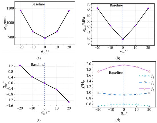
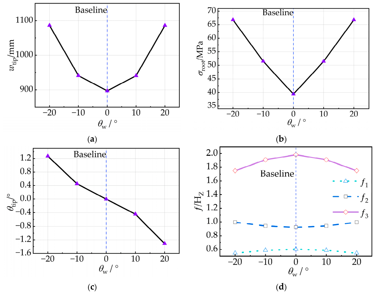
The corresponding structural responses are summarized in Figure 5.
Figure 5.
Effects of the shear-web inclination angle on structural responses: (a) flapwise tip deflection; (b) maximum equivalent stress; (c) tip twist angle; (d) first three natural frequencies.
Figure 5a,b show that both tip displacement and maximum stress increase with the magnitude of θw, with an approximately symmetric response about 0°. The baseline tip displacement is 897.04 mm. At ±10°, it increases to 941.25 and 941.04 mm, approximately 4.9% above the baseline value. At ± 20°, it further increases to approximately 1086 mm, corresponding to an increase of about 21.1%. Maximum stress is more sensitive to θw. It increases from 39.418 MPa at 0° to approximately 51.46 MPa at ±10° and 66.78 MPa at ±20°, representing increases of about 30.5% and 69.4%, respectively. These results indicate that increasing the shear-web inclination magnitude reduces the effective resistance to global bending deformation and alters the internal load-transfer path. The stress response is therefore more sensitive to θw than the overall displacement.
Figure 5c shows that the shear-web inclination angle provides strong directional control of the bend–twist response. As θw increases from −20° to +20°, the tip twist angle changes from 1.2699° to −1.3096° and approaches zero near 0°, giving an approximately antisymmetric response. The mean absolute twist angle is about 0.449° at ±10° and increases to approximately 1.290° at ±20°. Thus, increasing |θw| markedly amplifies the torsional response. The baseline twist angle at θw = 0° is approximately −0.0035309°. Therefore, ratios normalized by the baseline twist magnitude are sensitive to the small denominator and should not be interpreted as proportional changes in intrinsic bend–twist coupling stiffness. As discussed in Section 2.4, the computed twist may also include contributions from structural asymmetry and load eccentricity. Thus, the twist sign is used only to distinguish the rotation direction. Without defined aerodynamic inflow and blade-pitch references, it cannot be directly interpreted as twist-to-feather, twist-to-stall, or aerodynamic load alleviation. Figure 5d further shows that the first three natural frequencies respond differently to θw. With no modal-order exchange observed, increasing θw from 0° to 20° reduces the first and third natural frequencies from 0.60315 and 1.9837 Hz to approximately 0.5447 and 1.7497 Hz, respectively, corresponding to decreases of 9.7% and 11.8%. In contrast, the second natural frequency increases from 0.92339 to approximately 0.9944 Hz, an increase of 7.7%. These opposite trends suggest that shear-web inclination redistributes directional stiffness and coupling rather than producing a uniform change in overall stiffness.
Overall, increasing the magnitude of the shear-web inclination produces pronounced changes in the signed tip rotation, but also affects deformation, comparative stress response, structural mass, and low-order dynamic characteristics. These changes should be interpreted as global load-induced responses to the modified geometry rather than as direct evidence of enhanced intrinsic bend–twist coupling. Possible effects of load eccentricity relative to the sectional shear center were not quantified separately. Therefore, the shear-web inclination should be selected by considering the overall structural performance trade-offs.
3.3. Effect of Spar-Cap Off-Axis Ply Angle
To investigate the effect of spar-cap layup angle on the structural response and dynamic characteristics of the blade. The main-spar geometry, material properties, total laminate thickness, boundary conditions, and external loads were kept unchanged. Four layup cases were considered:0°, ±30°, ±45°, ±60°. The structural mass remained constant at 737.37 kg for all cases, eliminating the influence of mass variation on the response. The resulting responses are summarized in Figure 6.
Figure 6.
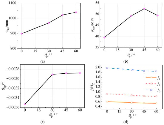
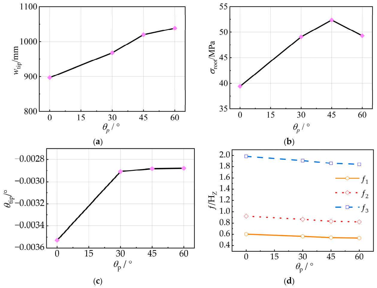
Effects of the spar-cap off-axis ply angle on structural responses: (a) flapwise tip deflection; (b) maximum equivalent stress; (c) tip twist angle; (d) first three natural frequencies.
Figure 6a,b summarize the static responses. The flapwise tip deflection increases from 897.04 mm for the baseline case to 967.55, 1019.4, and 1038.4 mm for the ±30°, ±45°, and ±60° cases, corresponding to increases of 7.86%, 13.64%, and 15.76%, respectively. This trend indicates a reduction in the effective spanwise bending stiffness as the fiber direction deviates from the primary load-carrying direction. The maximum equivalent stress shows a non-monotonic variation, increasing from 39.418 MPa at 0° to 49.060 MPa at ±30° and 52.365 MPa at ±45°, before decreasing to 49.281 MPa at ±60°. The ±45° case therefore produces the highest local stress level among the configurations investigated.
Figure 6c,d present the bend–twist and modal responses. The absolute tip twist angle increases by 17.61%, 18.32%, and 18.45% for the ±30°, ±45°, and ±60° cases, respectively, relative to the baseline. The variation becomes small beyond ±30°, indicating that a larger off-axis angle does not enhance the global bend–twist response under the present configuration. The first three natural frequencies also decreased with increasing off-axis ply angle. From 0° to ±60°, f1, f2 and f3 decrease by 11.42%, 10.93%, and 7.20%, respectively.
Overall, increasing the magnitude of the spar-cap off-axis ply angle increases flapwise deformation and lowers the low-order natural frequencies, while the absolute tip twist does not increase under the prescribed loading conditions. The CLT results show that A16 and A26 are approximately zero and B is negligible for the investigated balanced and symmetric laminates, whereas D16 and D26 remain nonzero in the off-axis configurations. For the ±30°, ±45°, and ±60° cases, the corresponding (D16, D26) pairs are (55.46, 21.28), (44.30, 44.30), and (21.28, 55.46) × 103 N·mm, respectively. These results indicate that changes in effective structural stiffness do not necessarily enhance the global bend–twist response. Nonzero laminate-level bending–twisting coupling terms do not, by themselves, guarantee increased global tip twist. These findings apply to the balanced and symmetric layups investigated under the prescribed loading conditions and should not be generalized to unbalanced laminates or other stacking sequences.
3.4. Effect of Off-Axis Ply Fraction
Building on the layup-angle analysis, this section further investigates the effect of off-axis ply content in the spar cap on the bend–twist coupling response. With the off-axis ply angle fixed at ±45°, three layup schemes, C0, C1, and C2, were defined by varying the proportions of 0° and ±45° plies in the root and mid-span primary load-bearing regions. C0 is the baseline case with an all-0° spar-cap layup. C1 corresponds to the ±45° case, in which four 0° plies in each of the M1_16, M1_14, M1_12, M1_10, and M1_8 regions were replaced by two +45° and two −45° plies. C2 was derived from C1 by further replacing four 0° plies with two additional +45° and two additional −45° plies in each of the M1_16, M1_14, and M1_12 regions, while the remaining regions were unchanged. The off-axis plies in both configurations were arranged in balanced and symmetric stacking sequences.
Table 9 presents the detailed ply counts, off-axis ply fractions, and stacking sequences for each laminate region in the C1 and C2 configurations.
Table 9.
Regional ply counts, off-axis ply fractions, and stacking sequences for the C1 and C2 configurations.
To distinguish laminate-level stiffness from the global bending-induced twist response, the CLT stiffness matrices were examined for the five configurations. Table 10 lists the independent components of the extensional stiffness matrix A and bending stiffness matrix D, together with the maximum absolute value of the extension–bending coupling matrix B. The matrices were extracted from ANSYS ACP at comparable locations in the upper spar-cap M1–16 region using consistent local reference directions and the stacking sequences defined in Table 9.
Table 10.
Local laminate stiffness matrix components of the investigated spar-cap configurations obtained from classical laminate theory.
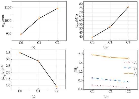
The three schemes use the same material system, total ply count, laminate thickness, and 0° layup configuration of the front and rear structural members. The structural mass remains constant at 737.37 kg, ensuring direct comparison among the three cases. The corresponding static and modal responses are summarized in Figure 7.
Figure 7.
Effects of the off-axis ply fraction on structural responses: (a) flapwise tip deflection; (b) maximum equivalent stress; (c) tip twist angle; (d) first three natural frequencies.
Figure 7a,b show that increasing the off-axis ply content increases both tip displacement and maximum stress. The tip displacement increases from 897.04 mm for C0 to 1019.40 mm for C1 and 1095.40 mm for C2, corresponding to increases of 13.64% and 22.11% relative to C0. The increase from C1 to C2 is 7.46%. Maximum stress shows a stronger response, increasing from 39.418 MPa for C0 to 52.365 MPa for C1 and 76.500 MPa for C2. These values correspond to increases of 32.85% and 94.07% relative to C0, respectively. The stress under C2 is also 46.09% higher than that under C1. These trends indicate that replacing part of the 0° plies with ±45° plies reduces the effective longitudinal load-bearing stiffness of the spar cap and redistributes the internal load, resulting in larger global deformation and higher local stress.
Figure 7c shows that increasing the off-axis ply content does not enhance the global twist response. The absolute tip twist angle decreases from 0.0035303° for C0 to 0.0028834° for C1 and 0.0009583° for C2. These reductions correspond to 18.32% and 72.85% relative to C0, respectively, while C2 is 66.76% lower than C1. Figure 7d shows a similar degradation in dynamic performance. From C0 to C2, the first three natural frequencies decreased by 18.96%, 17.77%, and 8.51%, respectively, with the first two modes showing greater sensitivity. Together with the increase in tip displacement, these reductions indicate an overall decrease in structural stiffness as the ±45° ply content increases.
In short, increasing the ±45° ply fraction redistributes the spar-cap stiffness and alters global structural performance. According to the CLT results in Table 10, from C0 to C2, the extensional stiffness A11 decreases by 33.49% from 865.66 to 575.77 × 10³ N/mm, while the bending stiffness D11 decreases by 35.84% from 4.079 to 2.617 × 10⁶ N·mm. Meanwhile, D16 and D26 increase from approximately to 99.68 × 10³ N·mm Despite these local coupling terms, the absolute tip twist decreases from 0.0035303° in C0 to 0.0009583° in C2 under the prescribed reference load. Thus, increasing the ±45° ply fraction does not enhance the global bend–twist response for the studied balanced and symmetric layups. This finding should not be generalized to unbalanced laminates or other stacking sequences not examined in this study.
4. Discussion
4.1. Relative Influence of Design Parameters on Structural Responses
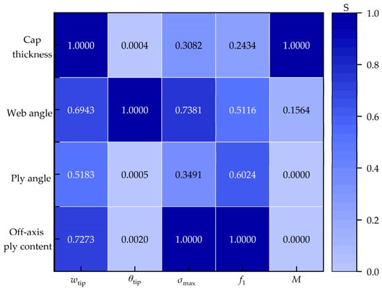
This section evaluates the relative influence of different main-spar design parameters on structural responses. Based on Equations (4) and (5), heatmaps of the relative influence matrix were constructed for the four parameter groups and response variables. The relative influence index S ranges from 0 to 1. The value of S = 1 indicates that the corresponding parameter causes the largest variation in each response within the investigated range. It should be noted that S quantifies only the magnitude of influence and does not indicate the direction of change. The increase or decrease in each response must therefore be identified from the original simulation results.
Figure 8 shows clear response selectivity among the design parameters. Spar-cap thickness has the greatest effect on tip displacement, followed by off-axis ply content and shear-web inclination angle, indicating that global bending deformation is mainly governed by spar-cap geometry and structural stiffness. The shear-web inclination angle has the strongest effect on tip twist angle and therefore dominates the global bend–twist response within the investigated range. Off-axis ply content has the greatest effect on maximum stress and the first natural frequency, suggesting a strong influence of layup parameters on local load transfer and low-order dynamic stiffness. Structural mass is mainly controlled by spar-cap thickness, whereas the shear-web inclination angle has only a minor effect and the other two parameters have negligible influence.
Figure 8.
Range-normalized relative influence matrix of the blade-spar design parameters on key structural responses.
The first three natural frequencies reported in this study were obtained under constant material properties and boundary conditions. Under actual operating conditions, temperature variations may alter the effective stiffness and modal behavior of composite wind turbine blades. Rezazadeh et al. [30] experimentally demonstrated that the modal properties of a scaled composite wind turbine blade vary with temperature, highlighting the importance of environmental effects in structural health monitoring. Therefore, the modal-frequency variations reported here should be interpreted as parameter-induced numerical responses under the prescribed modeling conditions. They should not be regarded as temperature-invariant indicators of in-service structural performance or damage.
In summary, no single design parameter dominates all structural responses; instead, the four variables exhibit clear response selectivity. The comprehensive evaluation should therefore consider the bend–twist response together with changes in stiffness, stress, natural frequency, and structural mass. However, the relative influence indices were derived from independent single-factor variations. Therefore, they do not account for interactions among the design variables. The resulting response rankings should not be directly extended to cases in which spar-cap thickness, shear-web inclination, and laminate parameters are varied simultaneously.
4.2. Bend–Twist Response and Structural Performance Trade-Offs
This section uses the bend–twist coupling response coefficient KBT together with the main structural responses to compare the overall effects and performance trade-offs of different design parameters. Table 11 summarizes the bend–twist coupling response indices for representative cases.
Table 11.
Bend–twist response indices for representative design cases.
When the spar-cap thickness was increased to 1.4t0, KBT increased from 0.00394 °/m for the baseline case to 0.00507 °/m. Meanwhile, the model mass increased from 737.37 kg to 887.18 kg, corresponding to an increase of approximately 20.3%. Together with the reduced tip deflection and increased natural frequencies, these results show that a thicker spar cap enhances global stiffness and low-order dynamic performance, but at the expense of a substantial mass increase.
The shear-web inclination angle has the strongest influence on the bend–twist response. At −20° and +20°, KBT reaches 1.16891 °/m and 1.20567 °/m, respectively, with opposite twist directions. However, the large ratios partly result from the very small baseline KBT and should therefore be interpreted together with the absolute values. These ratios should not be interpreted as proportional enhancements of intrinsic bend–twist coupling stiffness. Increasing the inclination magnitude also increases tip displacement, maximum equivalent stress in the selected spar-cap ply region, and structural mass. Thus, the shear-web inclination angle should be selected by balancing bend–twist coupling capability against structural load-bearing performance.
The two types of layering parameters exhibit different trade-off characteristics. When the spar-cap off-axis ply angle increases to ±60°, KBT decreases to 0.00277 °/m, compared with 0.00394 °/m for the baseline model. Increasing the off-axis ply fraction to C2 causes a more pronounced reduction, with KBT decreasing to 0.000875 °/m, accompanied by increased local stress and lower low-order natural frequencies. The local ABD results and global finite element responses describe different aspects of the structural behavior. Nonzero D16 and D26 terms do not necessarily lead to greater global tip twist. The response also depends on the spanwise ply distribution, box-spar geometry, load position, and boundary conditions. Therefore, the present conclusions are limited to the balanced and symmetric layups and loading conditions examined. Other stacking sequences, including unbalanced layups, require separate evaluation.
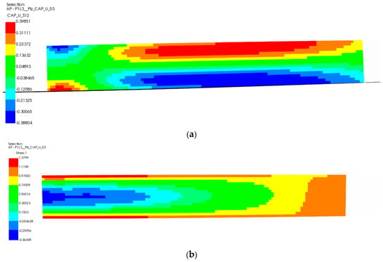
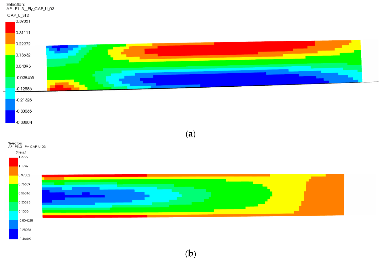
To further illustrate the local stress response in the spar-cap region investigated for the ±45° ply modification, Figure 9 presents the in-plane shear-stress τ12 distributions of selected analysis plies at the same U_03 spar-cap region in the C0 and C1 configurations under the prescribed flapwise bending load. As shown in Figure 9a, the selected 0° ply in the baseline configuration C0 exhibits a nonuniform shear-stress distribution, with τ12 ranging from −0.38804 to 0.39851 MPa. In contrast, Figure 9b shows the corresponding local response of a selected off-axis ply in C1, where the shear stress ranges from −0.46449 to 1.3799 MPa. The different distributions illustrate the influence of the modified laminate orientation on the local stress response within the investigated spar-cap region. However, because these stresses are expressed in their respective ply material coordinate systems, the values should not be directly interpreted as a coordinate-independent measure of reinforcement effectiveness. As demonstrated by the global responses in Figure 7, increasing the ±45° spar-cap ply content in the investigated configurations is accompanied by increased tip displacement and maximum equivalent stress, together with a reduced absolute bending-induced twist angle. Therefore, the newly added contours provide a visualization of the local stress response in the region considered for ±45° reinforcement, rather than evidence of an independently optimized reinforcement layout.
Figure 9.
In-plane shear-stress τ12 distributions of representative analysis plies in the U_03 spar-cap region under the prescribed flapwise bending load: (a) the 0° spar-cap ply in the baseline configuration C0; (b) a selected ±45° spar-cap ply in the modified configuration C1.
The selected-ply stress was defined as the maximum averaged equivalent stress in the CAP_01 root evaluation region. Its relative difference between M2 and M3 was 4.072%. However, no independent boundary-condition sensitivity analysis was performed, and the local peak stress may be affected by the idealized fully fixed root constraint. The 94.07% increase in the C2 stress response represents a relative numerical change under the prescribed loading conditions, not a proportional reduction in material strength or structural safety margin.
The reported trade-offs were evaluated under the prescribed reference loading and idealized boundary conditions. Therefore, the numerical responses should not be interpreted as evidence of operational load alleviation or structural safety under realistic turbine loading. Since ply-level failure, buckling, and fatigue were not assessed, the equivalent stress is used only as a comparative response measure.
In summary, the design of each parameter should be based on overall performance trade-offs rather than on a single response metric. Spar-cap thickness is constrained by weight requirements, while the shear-web inclination angle is limited by load-bearing capacity. Off-axis ply angle and ±45° ply content are jointly constrained by stiffness, stress, and dynamic performance. Therefore, simply increasing the off-axis ply content is not an effective strategy for improving bend–twist performance. Nevertheless, these findings are based on single-factor comparisons. The interaction effects among spar-cap thickness, shear-web inclination, and laminate configuration have not yet been quantified. Further factorial or response-surface analyses are needed to assess whether the observed trends remain valid when multiple parameters vary simultaneously. Such analyses would also help identify feasible combined design configurations.
5. Conclusions
Using a consistent modeling framework with identical loading and boundary conditions, the effects of spar-cap thickness, shear-web inclination angle, spar-cap layup angle, and off-axis ply content on response selectivity and performance trade-offs were compared. The main conclusions are as follows:
- (1)
- The four design parameters exhibit distinct response selectivity. Spar-cap thickness mainly governs global bending stiffness and structural mass, while the shear-web inclination angle has the strongest influence on the bend–twist response and twist angle. Spar-cap layup angle and off-axis ply content primarily affect anisotropic stiffness distribution, local stress, and low-order dynamic characteristics. No single parameter simultaneously optimizes all response metrics.
- (2)
- Within the investigated range, the shear-web inclination angle is the most influential geometric parameter for the bend–twist response. At −20° and +20°, the bend–twist response indices reach approximately 1.17 °/m and 1.21 °/m, respectively, with opposite twist directions. However, larger inclination magnitudes increase tip displacement and maximum stress, slightly increase structural mass, and reduce some low-order natural frequencies. Therefore, shear-web inclination should be assessed by balancing bending-induced twist against deformation, comparative stress response, structural mass, and low-order dynamic performance.
- (3)
- Under the symmetric balanced layup, increasing the off-axis ply angle or content does not enhance the global bend–twist response and leads to stiffness and stress penalties. The twist-to-deflection response index decreases to 0.00277 °/m for the ±60° configuration and to 0.000875 °/m for C2, compared with the baseline value of 0.00394 °/m. These results are specific to the balanced and symmetric laminate configurations investigated under the prescribed loading conditions. The CLT results show that the off-axis configurations retain nonzero local bending–twisting stiffness terms D16 and D26, even when the extension–bending coupling matrix B is negligible. These local terms alone do not determine the global response of the equivalent box spar, which also depends on the stacking sequence, structural geometry, and loading conditions. Further comparisons with unbalanced or differently sequenced laminates are needed before broader conclusions about material coupling can be drawn.
- (4)
- The parameter–response relationships and trade-off patterns clarify the distinct roles of global stiffness, geometry-induced bend–twist coupling, and material anisotropy. Different parameters dominate different structural responses and involve distinct performance trade-offs. These relationships provide a deterministic basis for subsequent reliability analysis and multi-objective optimization of wind turbine blade main spars.
Supplementary Materials
The following supporting information can be downloaded at: https://www.mdpi.com/article/10.3390/app162110837/s1. Table S1: Local web midsurface lengths.
Author Contributions
Conceptualization, H.M. and J.G.; methodology, H.M.; software, H.M.; validation, H.M., Y.Y. and R.P.; formal analysis, H.M.; investigation, J.G.; resources, Y.Y.; data curation, R.P.; writing—original draft preparation, H.M.; writing—review and editing, H.M., J.G., Y.Y. and R.P.; visualization, H.M.; supervision, J.G.; project administration, J.G. and Y.Y.; funding acquisition, J.G. All authors have read and agreed to the published version of the manuscript.
Funding
This work was supported by Xinjiang Uygur Autonomous Region Central Guidance Local Science and Technology Development Fund Project, grant numbers ZYYD2026QY07 and ZYYD2025JD07.
Institutional Review Board Statement
Not applicable.
Informed Consent Statement
Not applicable.
Data Availability Statement
The original contributions presented in this study are included in the article. Further inquiries can be directed at the corresponding author.
Conflicts of Interest
The authors declare no conflicts of interest.
References
- Global Wind Energy Council. Global Wind Report 2026; Global Wind Energy Council: Lisbon, Portugal, 2026. [Google Scholar]
- Gao, L.; Li, B.; Hong, J. Effect of wind veer on wind turbine power generation. Phys. Fluids 2021, 33, 015101. [Google Scholar] [CrossRef] [Scilit]
- Li, C.; Yang, C.; Ni, A.; Wang, J.; Song, Q. Application and development of composite materials in large-scale wind turbine blade. Acta Mater. Compos. Sin. 2023, 40, 1274–1284. (In Chinese) [Google Scholar]
- Stäblein, A.R.; Hansen, M.H.; Verelst, D.R. Modal properties and stability of bend–twist coupled wind turbine blades. Wind Energy Sci. 2017, 2, 343–360. [Google Scholar] [CrossRef] [Scilit]
- Li, B.; Tian, D.; Wu, X.; Meng, H.; Su, Y. The impact of bend–twist coupling on structural characteristics and flutter limit of ultra-long flexible wind turbine composite blades. Energies 2023, 16, 5829. [Google Scholar] [CrossRef] [Scilit]
- Wang, H.; Miao, W.; Li, C.; Zhang, L.; Yan, Y.; Li, Z.; Yue, M. Study on bend–twist coupling characteristics of web offset for large wind turbine blades. J. Mech. Strength 2023, 45, 887–893. (In Chinese) [Google Scholar]
- Zhao, X.; Jiang, W.; Liang, Z.; Zhao, Y. Passive load reduction performance of bend–twist coupling in large flexible wind turbine blades. Compos. Struct. 2025, 371, 119421. [Google Scholar] [CrossRef] [Scilit]
- Serafeim, G.P.; Manolas, D.I.; Riziotis, V.A.; Chaviaropoulos, P.K.; Saravanos, D.A. Optimized blade mass reduction of a 10 MW-scale wind turbine via combined application of passive control techniques based on flap-edge and bend–twist coupling effects. J. Wind Eng. Ind. Aerodyn. 2022, 225, 105002. [Google Scholar] [CrossRef] [Scilit]
- Chen, C.; Wang, T.; Wang, L. Sensitivity study of the influence of blade sectional stiffness parameters on the aeroelastic response of wind turbines. Front. Energy Res. 2021, 9, 707082. [Google Scholar] [CrossRef] [Scilit]
- Shakya, P.; Sunny, M.R.; Maiti, D.K. Nonlinear flutter analysis of a bend–twist coupled composite wind turbine blade in time domain. Compos. Struct. 2022, 284, 115216. [Google Scholar] [CrossRef] [Scilit]
- Ma, X.; Sun, J.; Chen, Y.; Peng, X. Investigation of influence of pre-bend and backward swept geometries on wind turbine blade loads considering bend–twist coupling. Acta Energiae Solaris Sin. 2025, 46, 1–10. (In Chinese) [Google Scholar]
- Wang, H.; Miao, W.; Zhang, L.; Li, C.; Li, Z. Research on main girder web configuration of bend–twist coupling blade of large wind turbine with composite laying. Acta Energiae Solaris Sin. 2023, 44, 29–38. (In Chinese) [Google Scholar]
- Wang, H.; Miao, W.; Li, C.; Li, Z.; Yue, M.; Zhu, H. Structural performance analysis of large wind turbine blade based on main beam web offset and composite layup. Proc. CSEE 2023, 43, 7509–7518. (In Chinese) [Google Scholar]
- Wang, H.; Miao, W.; Li, C. Structural characteristic analysis of new type bend–twist coupling blades of large wind turbine. J. Mech. Strength 2024, 46, 668–674. (In Chinese) [Google Scholar]
- Dong, X.; Sun, P.; Zhang, L.; Wang, Z. Multi-objective optimization of ply parameters for wind turbine blade. J. Mech. Eng. 2022, 58, 165–173. (In Chinese) [Google Scholar] [CrossRef] [Scilit]
- Fu, L.; Jiang, X.; Sun, Z.; Wen, S.; Gao, M.; Tian, R. Influence of carbon/glass hybrid fiber layup structure on the bending–twisting coupling behavior of wind turbine blades. Acta Mater. Compos. Sin. 2023, 40, 3912–3920. (In Chinese) [Google Scholar]
- Li, Z.; Zhang, Y.; Miao, T.; Ning, W.; Bao, H.; Li, H. Influence of spar structural parameters on 6 × 6 sectional stiffness matrix and aeroelastic stability of wind turbine blades. Eng. Mech. 2026. online first (In Chinese) [Google Scholar]
- Kou, H.; Zhao, H.; Wei, K.; Yang, B. Optimization of wind turbine blade beam cap layup based on grid search method. Acta Energiae Solaris Sin. 2025, 46, 84–90. (In Chinese) [Google Scholar]
- Tang, X.; Li, K.; He, W.; Chen, R.; Peng, R. Flutter correlation analysis and aeroelastic optimization of wind turbine blades under multi-conditions. J. Mech. Eng. 2024, 60, 300–314. (In Chinese) [Google Scholar]
- Hermansen, S.M.; Lund, E. Multi-material and thickness optimization of a wind turbine blade root section. Struct. Multidiscip. Optim. 2024, 67, 107. [Google Scholar] [CrossRef] [Scilit]
- Wu, S.; Zhang, H.; Zhang, L.; Wang, L.; Sun, X.; Maeda, T.; Cai, C.; Li, Q. Multi-Objective Structural Optimization of Long Flexible Wind Turbine Blades for Enhanced Lightweight and Reliability. Energy 2025, 336, 138487. [Google Scholar] [CrossRef] [Scilit]
- Jang, Y.; Kim, H.; Kang, K. Progressive Failure Analysis for 5MW-Class Wind Turbine Composite Blades with Debonding Damage based on CZM Method. Appl. Sci. 2022, 12, 12973. [Google Scholar] [CrossRef] [Scilit]
- Kim, H.-G.; Kang, K.-W. Assessment of fatigue crack growth characteristics of laminated biaxial/triaxial hybrid composite in wind turbine blades. Appl. Sci. 2024, 14, 7929. [Google Scholar] [CrossRef] [Scilit]
- He, F.; Zheng, X.; Luo, W.; Zhong, J.; Huang, Y.; Ye, A.; Qiu, R.; Ma, H. Collaborative optimization of aerodynamics and wind turbine blades. Appl. Sci. 2025, 15, 834. [Google Scholar] [CrossRef] [Scilit]
- Jeong, W.; Park, H. Structural Design and Safety Analysis for Optimized Segmentation of Wind Turbine Blades with Composite Materials. Appl. Sci. 2025, 15, 11445. [Google Scholar] [CrossRef] [Scilit]
- Civera, M.; Surace, C. Non-Destructive Techniques for the Condition and Structural Health Monitoring of Wind Turbines: A Literature Review of the Last 20 Years. Sensors 2022, 22, 1627. [Google Scholar] [CrossRef] [Scilit]
- Jonkman, J.; Butterfield, S.; Musial, W.; Scott, G. Definition of a 5-MW Reference Wind Turbine for Offshore System Development; NREL/TP-500-38060; National Renewable Energy Laboratory: Golden, CO, USA, 2009. [Google Scholar]
- Siddiqui, M.S.; Rasheed, A.; Kvamsdal, T.; Tabib, M. Quasi-static and dynamic numerical modeling of full-scale NREL 5 MW wind turbine. Energy Procedia 2017, 137, 460–467. [Google Scholar] [CrossRef] [Scilit]
- Walsh, J.M. Composite Material Bend–Twist Coupling for Wind Turbine Blade Applications. Master’s Thesis, University of Wyoming, Laramie, WY, USA, 2009. [Google Scholar]
- Rezazadeh, N.; De Luca, A.; Lamanna, G.; Annaz, F.; de Oliveira, M. A novel interpretable domain adaptive framework for robust damage detection in composite structures under environmental variability. Struct. Health Monit. 2026. [Google Scholar] [CrossRef] [Scilit]

Disclaimer/Publisher’s Note: The statements, opinions and data contained in all publications are solely those of the individual author(s) and contributor(s) and not of MDPI and/or the editor(s). MDPI and/or the editor(s) disclaim responsibility for any injury to people or property resulting from any ideas, methods, instructions or products referred to in the content. |
© 2026 by the authors. Licensee MDPI, Basel, Switzerland. This article is an open access article distributed under the terms and conditions of the Creative Commons Attribution (CC BY) license.