


Abstract
Onboard satellite elapsed time clocks are a crucial element of every space mission. They are often implemented in field-programmable gate array (FPGA) devices and are responsible for counting and providing elapsed time to other spacecraft modules. Many mission-specific components used for research purposes place high demands on the accuracy of time measurement. Therefore, it is necessary to ensure the precision of the measured time. This is most often achieved by cyclically synchronising the elapsed time counted by the Local On-Board Time (LOBT) module with an external reference signal. Typically, the reference signal is the pulse-per-second (PPS) signal. Naturally, the LOBT synchronisation process must meet a number of requirements. The accuracy and speed of elapsed time tuning are crucial. The LOBT logical structure implemented in FPGA devices should also be characterised by the lowest possible use of logical resources and minimal power consumption. The synchronisation process requirements and implementation requirements are often contradictory. In this article, the authors propose a hardware-based LOBT smooth resynchronisation method in which both criteria are subjected to in-depth analysis during computational considerations, simulation, and implementation in an FPGA device. The article contains a series of experimental results and conclusions that indicate the range of feasible solutions in terms of both criteria.
1. Introduction
Time management is a fundamental aspect of spacecraft operation, as numerous onboard functions depend on the availability of a reliable and accurate time reference. Satellite subsystems, including telemetry, telecommand processing, payload operations, navigation, and attitude control, require precise synchronisation to ensure deterministic behaviour and correct event sequencing. To address these requirements, modern spacecraft architectures typically employ dedicated onboard time distribution mechanisms that provide a common temporal reference to all subsystems. The onboard time system must also maintain continuity during communication outages and support synchronisation with external time sources, such as Global Navigation Satellite Systems (GNSS) [1] or ground control stations. As spacecraft systems become increasingly distributed and autonomous, robust time synchronisation mechanisms remain essential for mission reliability and the successful execution of time-critical operations.
A commonly adopted concept in space systems is the Central On-Board Time (COBT), which represents the master time reference generated and maintained by the spacecraft’s central timing unit or onboard computer. COBT serves as the authoritative source of time for the entire satellite and is distributed to individual subsystems through dedicated communication interfaces and synchronisation protocols. In contrast, Local On-Board Time (LOBT) refers to the local time maintained by a particular subsystem or payload unit. LOBT is typically derived from COBT but may continue operating independently for limited periods using a local oscillator when synchronisation updates are unavailable. The relationship between COBT and LOBT is critical for ensuring temporal consistency across distributed spacecraft architectures and for enabling accurate timestamping of scientific and engineering data.
The Pulse Per Second (PPS) signal is widely used as a hardware synchronisation mechanism for aligning local clocks with the central spacecraft time reference. PPS provides a precise timing marker, usually generated once every second, allowing subsystems to correct clock drift and maintain synchronisation with COBT. The combination of COBT, LOBT, and PPS forms the foundation of onboard time management in modern satellites, supporting deterministic operation, event scheduling, data correlation, and fault diagnosis. An important aspect is maintaining proper synchronisation between the local time source and the standard PPS signal [2]. This may be crucial if the external signal from the Global Positioning System (GPS) source is lost. To mitigate these risks, autonomous time synchronisation capabilities are essential to enhance system reliability. The paper [3] presents a method of interpolating a delay line using the internal feedback structure of a field-programmable gate array (FPGA) to measure time intervals shorter than the system clock cycle. Combined with a pulse counting method, this extends the interpolation measurement range of the delay line. Additionally, the FPGA is used to control the relevant circuit to regulate the output power of the local crystal based on the time interval output value. Following a long-term test, the accuracy of the synchronous PPS signal obtained using this method is less than 700 ps. The on-board temperature-compensated quartz oscillator in conjunction with radio-based synchronisation was applied in the Hypersat microsatellite platform [4]. Another approach involves eliminating the sawtooth errors characteristic of PPS signals [5]. To optimally control clock errors, a ramp-predictive finite impulse response (FIR) filter can be used, which is known to be optimal for clock models with wide averaging horizons. A low-pass filter was used to smooth the hold filter output between the optimally predicted points [6]. In [7], the use of the Sliding Mode Control algorithm for frequency and phase synchronisation of a local oscillator is proposed. The article [8] proposes a clock control method using a second-order, type-2 digital phase-locked loop (DPLL), equivalent to a two-state Kalman filter with delay. Furthermore, a concise and effective approach to parameter selection was proposed, which is not easy in many closed-loop methods. The implementation of a phase-locked loop (PLL) controller is described in the article [9]. The authors focused on the implementation of a digital PLL in an FPGA, where the control is based on a closed-loop system and the sensing element is an optical tachometer.
Proportional-integral-derivative (PID) control is often used in clock synchronisation algorithms. The traditional clock synchronisation method based on the PID algorithm performs calculations and feedback control exclusively with respect to a single variable, such as frequency. The time accuracy error of the clock signal source is significant, and it even exhibits an inherent deviation. By utilising the integral relationship between frequency and time, a new two-variable PID control algorithm for precise clock regulation was proposed in the article [10]. Time is treated as a limiting variable, which allows the time deviation to converge.
Time synchronisation can be achieved either in software or in hardware. FPGAs are increasingly being used for this purpose. In the article [11], a new time synchronisation scheme based on an FPGA is proposed. In contrast to the previous comparison of two existing solutions—hardware and software—it is demonstrated that a better approach to time synchronisation can be developed, characterised by cost-effective hardware, a practical system architecture and versatility of application, not only in the context of GPS integration with an Inertial Measurement Unit, but also in relation to other multi-sensor navigation systems. An external PPS clock was used to generate a synchronised clock in the local frequency domain in [12]. The PPS clock was directly tracked and locked by FPGA logic, while the multi-clock mathematical models were built to correct PPS clock self-jitter using a central processing unit (CPU) implemented in the FPGA. Paper [13] presents a method for enhancing the stability of temperature-compensated voltage-controlled crystal oscillator (TCVCXO) clocks by utilising the PPS signal and a high-resolution time interval counter. The presented method involves adjusting the oscillator’s frequency through a reference voltage set by a digital-to-analogue converter (DAC), while the voltage value is correlated using a precision time interval counter implemented in an FPGA device. Implementations based on physical phenomena (e.g., metastability) enable exceptionally high measurement precision, down to the picosecond level [14,15].
Time synchronisation in spacecraft relies not only on the PPS signal but also on methods associated with interfaces. The article [16] describes how SpaceWire time codes can be used to synchronise time across various spacecraft subsystems, as well as to maintain a common time reference necessary for coordinating operations on board. The time resolution in the SpaceWire standard is limited, but it can be improved by using the high-resolution extension [17]. Furthermore, the size of the extension remains very small, allowing for easy implementation in any space-grade FPGA. Such an extension combines the advantages of the SpaceWire standard and high-resolution time stamping without the need for another dedicated interface for clock distribution and synchronisation.
The paper [18] presents a draft of the European Cooperation for Space Standardization (ECSS) protocol for the transmission and synchronisation of time in the Consultative Committee for Space Data Systems (CCSDS) Unsegmented Code (CUC) format over SpaceWire networks. The implementation of mechanisms to limit jitter and drift is based on a simple measurement of the time intervals between incoming SpaceWire time codes using a local clock. Statistical information is collected, which is then used to calculate an average correction value applied to modify the frequency synthesiser supplying input signals for time generation. By controlling the frequency synthesiser, the time remains stable without any drift resulting from the oscillator or crystal used to generate the local clock.
Another area where time synchronisation is crucial is data transmission and the improvement of navigation via satellite constellations [19]. When operating in autonomous mode, the constellation uses links between satellites to compare time across the entire satellite network, maintaining a consistent system time reference and achieving synchronisation. To enhance the system’s ability to operate autonomously, it is essential to establish and maintain a reference time for the constellation based on measurement data from inter-satellite links [20].
A separate issue is synchronising the local oscillator with the PPS signal after it has been lost and then recovered. When the PPS signal is recovered, an immediate time jump is not usually performed, as a sudden change in time could disrupt telemetry timestamps, cause errors in task schedules, and interfere with the operation of navigation filters.
To sum up, a good holdover implementation consists of:
- Oscillator characterisation during normal operation.
- Self-compensation during PPS loss.
- Smooth resynchronisation after PPS recovery (time shall never move backwards), which is the main focus of this work.
Complex digital systems are often implemented in FPGAs. An important analysis of the suitability of commercial SRAM-FPGA systems for challenging orbits (LEO, GEO, Molniya) is presented in [21]. The authors present a mathematical model for estimating mean time to failure (MTTF) and demonstrate that combining redundancy with continuous memory flushing enables safe and stable space missions. A review that discusses in detail TMR (Triple Modular Redundancy) techniques and error correction techniques at the VHDL/Verilog code level in satellite applications is presented in [22]. The article [23] focuses on evaluating scrubbing techniques (triple reading and configuration error correction without interrupting system operation) in an FPGA. It demonstrates how, thanks to appropriate algorithms, commercial off-the-shelf (COTS) integrated circuits become a cost-effective alternative to expensive dedicated (rad-hard) circuits in less critical satellite instruments.
The synthesis and implementation process for FPGAs is extremely complex. Furthermore, considering the requirements for implementations intended for space applications, this issue becomes crucial. The question arises as to which synthesis requirements are particularly important in these applications. The first of these is, of course, reducing the power consumption of the implemented system [24,25,26]. The power balance in space missions is limited, and it becomes necessary to design structures implemented in FPGAs so as to limit the dynamic power (resulting from the circuit switching). There are suitable techniques for designing both combinational circuits [27,28] and finite state machines (FSMs) [29,30,31]. The second is limiting the number of FPGA resources used. Limiting the number of look-up tables (LUTs), flip-flops (FFs) or other blocks used leads to improved reliability and cost reduction. There are techniques related to decomposition [32,33] or technological mapping [34,35], which lead to a reduction in logical resources. An important aspect of synthesis in space applications, as already noted in the previous paragraph, is minimising the effects of radiation on the system. The key here is to ensure appropriate mitigation through triple modular redundancy mechanisms [36,37], scrubbing [38,39,40,41], or appropriate coding [42,43].
The main contribution of this article is the presentation of the concept of an LOBT module synchronised with an external PPS signal. A new element is the method for determining the incremental constant correction based on the detuning error. A crucial element of the article is the selection of the parameters necessary to determine this correction to achieve smooth resynchronisation. To this end, the article contains a series of theoretical analyses, simulations, and implementation results.
The article is organised as follows. Section 2 presents the unsegmented time format and the general concept of the LOBT module. Section 3 examines possible methods for synchronising the LOBT counter with an external PPS signal. Section 4 focuses on the idea of using incremental constant correction. Section 5 describes the parameter selection methods for this concept. Section 6 and Section 7 contain the experimental results and conclusions, respectively.
2. Theoretical Background
A crucial element of a spacecraft’s onboard computer is the elapsed time clock. The LOBT module is responsible for measuring this time based on external timing pulses. Naturally, the way this time is represented is crucial to the design of this module. This issue is described in [44]. Several formats for representing elapsed time can be distinguished:
- Day Segmented Time Code (CDS),
- Calendar Segmented Time Code (CCS),
- ASCII Calendar Segmented Time Code (ASCII),
- and the most common form, Unsegmented Time Code (CUC).
Each of these formats contains two fields:
- Preamble Field (P-Field), containing information about the time encoding parameters and method,
- and Time Field (T-Field), containing information about the time directly.
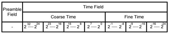
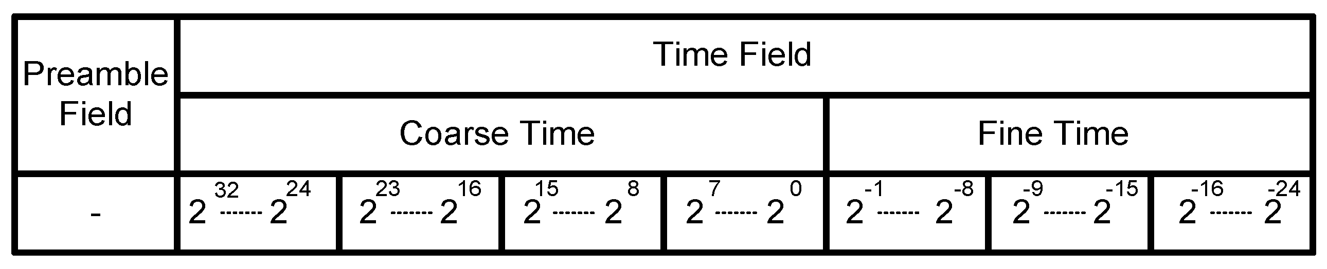
In the case of the CUC format, the T-Field is a direct reflection of the bit counter—the more significant 32 bits correspond to the number of seconds (Coarse Time), while the remaining less significant 24 bits are the fractional part (Fine Time). Therefore, it can be concluded that the integer part is associated with 4 octets and the fractional part with 3. Each octet in the T-Field represents the state of 8 consecutive bits of a binary counter, cascaded with neighbouring counters, which rolls over modulo 256. The time code represented by the T-Field should increase monotonically, never in reverse—time shall never move backwards. Generally, the entire T-Field specifies the number of time units that have passed since the beginning of the defined epoch (the epoch is often assumed to be 1 January 1958; other variants are also possible). The content of Coarse Time is incremented exactly every 1 s, so it can be easily determined that the increment of the least significant bit of Fine Time must take place every 60 ns (2−24 s). The integer part determines the time in the range up to 136 years. The organisation of the CUC format is shown in Figure 1.
Figure 1.
CCSDS Unsegmented Time Code Format.
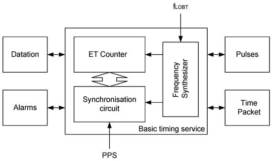
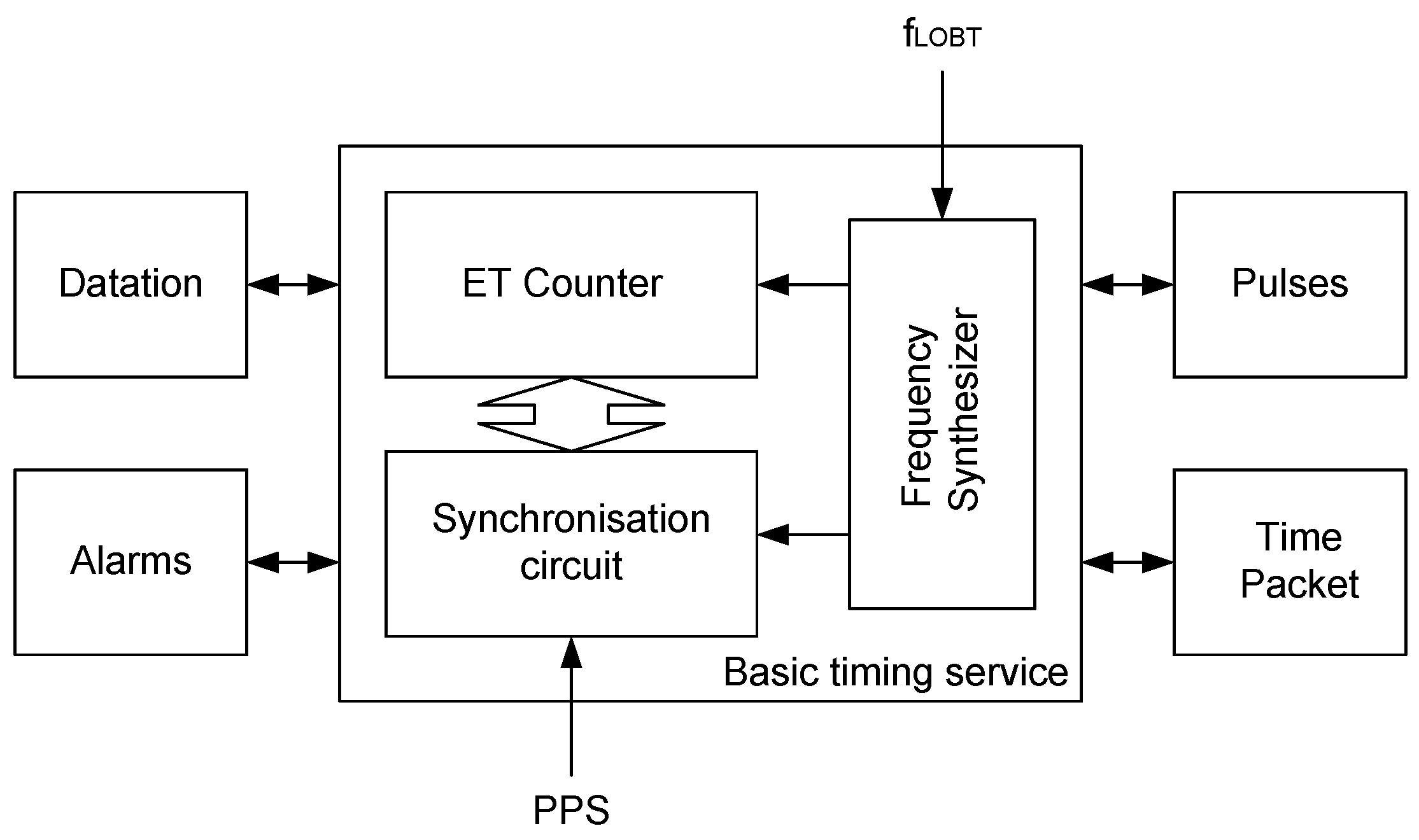
The LOBT module implemented in the FPGA device is responsible for counting time in an appropriate format. Analysing the documentation, in particular [45,46], the general structure of this module can be implemented as shown in Figure 2.
Figure 2.
The designed LOBT architecture block diagram.
The basic functionality of LOBT is time measurement. The core of this module implements basic timing services. For this purpose, the Elapsed Time (ET) Counter is incremented with the appropriate increment based on a signal generated by the Frequency Synthesiser (FS). The FS block generates counter increments based on a supplied clock signal with a frequency of fLOBT. In many cases, it is necessary to periodically synchronise the counter with an external PPS synchronisation signal, which is handled by the Synchronisation Circuit block in Figure 2.
In addition to supporting basic timing services, the LOBT module can support a number of additional services. The most popular include time-stamping of external events (Datation), time alarms (Alarms), pulse generation (Pulses), and the generation of complex time packets (Time Packet).
In many applications, synchronising the ET Counter with an external reference time signal is necessary to ensure time accuracy. This is caused by a number of adverse phenomena of various kinds. These may include technological phenomena (e.g., the effect of temperature on fLOBT stability), physical phenomena (e.g., relativistic phenomena), or phenomena related to the LOBT configuration (e.g., initial time setting). Therefore, it becomes necessary to automatically tune the LOBT to an external reference signal. Typically, this signal is the PPS signal. A characteristic feature of the PPS signal is that the time elapsed between successive rising edges of the signal corresponds to exactly 1 s.
Knowing the functionality and requirements for the LOBT module, the question arises about the hardware implementation of this system, in particular taking into account PPS synchronisation.
3. LOBT Implementation
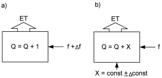
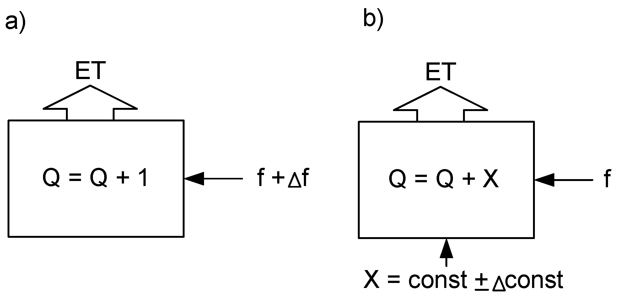
When considering various variants of the LOBT module implementation, it is worth noting that the implementation of the ET counter itself is conventional. However, the method of incrementing it may be different. Two approaches can be distinguished here. The first is one in which an advanced frequency synthesiser (FS) provides the frequency driving the increment of the least significant bit of the Fine Time part (60 ns). This approach requires an extensive FS block, and the time correction consists of correcting this frequency. The second approach is to extend the counters towards Fine Time with additional bits. In this case, incrementing consists of successively adding a precisely defined constant value in each clock cycle, and correction consists of modifying this constant. Both solutions are illustrated in Figure 3.
Figure 3.
Counting process of the ET counter: with constant increment (a), with constant frequency (b).
In the case of the approach in Figure 3a, the correction is associated with a change in the frequency f by a constant increment value (equal to 1). In the case of the approach in Figure 3b, the correction consists of correcting the increment constant at a constant frequency f.
The time counting process itself is relatively simple. However, taking into account synchronisation makes the process significantly more complicated. Simple approaches based on Fine Time zeroing have a number of disadvantages, such as a step change in time, possible temporary counting of time backwards, etc. In general, this approach would be too risky in many cases. Alternatively, one can imagine approaches in which certain asynchronous pulses would appear at the counter output to correct its value forward or block some of the clock pulses, causing the counting to slow down. However, these approaches are impractical, complicated and carry a high risk of metastability. Taking all this into account, in practice synchronisation should be associated with either a correction of the increment constant or a change in the increment frequency. In practice, it is easier to modify the increment constant. In this situation, the question arises of how to do it in practice and what problems it involves.
4. Successive Synchronisation of the ET Counter
In order to fully discuss the indicated problem, it is crucial to introduce the concept of detuning error e. The detuning error will correspond to the time between the appearance of the rising edge of the PPS pulse and the moment of increment of the Coarse Time part (reloading the Fine Time counter). Naturally, this error can take both positive values, when the Coarse Time increment occurred before the rising edge of the PPS signal, and negative values, when the Coarse Time increment occurred after the rising edge of the PPS signal. This error can be expressed both in time units and as the value of the Fine Time counter (which seems more practical) between these two indicated events. The change in the Fine Time value occurs every 60 ns.
The fractional part (Fine Time) of the ET counter should reload exactly every 1 s. The essence of the constant-frequency approach is to assume a certain, unchanging counter clock frequency. For our purposes, let us assume this frequency is 100 MHz (fLOBT = 100 MHz). In practice, this frequency is easily achieved and does not require an extensive FS block. Naturally, from the synchronisation point of view, the value of fLOBT should be a power of two (e.g., 16,777,216 Hz); in practice, however, this is inconvenient from the perspective of implementing other modules.
Let m denote the number of bytes in the fractional part of the counter. According to the standard [44], this counter should be 24-bit (m = 3). Note, however, that 224 = 16,777,216, while 224/100 MHz = 0.16777216. This means that to achieve a reload every 1 s, it must be incremented by a specified fractional value (0.16777216) every clock cycle (fLOBT). Naturally, incrementing the counter in this form by a fractional value is impractical. The solution to this problem is to extend the counter with additional bytes. In general, the fractional part counter can have any number of bytes. However, the most significant 24 bits always constitute the Fine Time. Incrementation involves cyclically increasing the counter’s content by cyclically adding a suitably chosen constant so that the least significant bit of Fine Time changes every 60 ns. Of course, the width of the fractional counter defines the value of the constant that must be periodically added to the counter. As seen above, for m = 3, the incrementing constant is fractional.
Let us consider different widths of the numerator of the fractional part. The appropriate calculations are presented in Formulas (1).
m = 4, 232/100 MHz = 43
m = 5, 240/100 MHz = 10,995
m = 6, 248/100 MHz = 2,814,750
Depending on the fLOBT clock and the counter width m, an appropriate constant must be added to the counter in each cycle.
The essence of the constant frequency approach is that the correction consists of a more reliable, small change in the designated constants to synchronise the counter with the PPS signal. Of course, the synchronisation process is a successive process extended over time. The counter adjusts itself between successive rising edges of the PPS signal. It is necessary to analyse how effective this process is for different values of m. The smallest possible change in the implementation step is, of course, a change of 1. Therefore, it is necessary to determine what time compensation ∆t1 will result from changing the value of the increment constant for different values of m. This is presented in Formulas (2).
m = 4, ∆t1 = 1/43 = 23.255 ms
m = 5, ∆t1 = 1/10,995 = 90.95 µs
m = 6, ∆t1 = 1/2,814,750 = 355.27 ns
In relation to Fine Time, where the least significant bit changes every 60 ns, the change in the Fine Time counter occurs when the increment constant changes by 1. This parameter is marked as ∆N1 and presented in the form of dependency (3).
m = 4, ∆N1 = 23.255 ms/60 ns = 387,597
m = 5, ∆N1 = 90.950 µs/60 ns = 1516
m = 6, ∆N1 = 355.27 ns/60 ns = 6
Looking at the results obtained, it can be concluded that expanding the numerator to m = 4 is far from sufficient. The smallest possible correction will cause changes in the Fine Time counter by a value of 387,597, which corresponds to over 23 ms. Also, expanding the numerator to m = 5 is inefficient. Changing the counter with a resolution of 1516 in the tuning process causes synchronisation with an accuracy of 90.95 µs (the expected accuracy in the worst cases should be single µs). Only extending the counter to m = 6 makes it possible to tune Fine Time to the PPS signal in such a way that the time difference will be 355 ns (the Fine Time counter can therefore differ by a maximum of 6 values). The question arises whether the value of m can be increased further. It turns out that for the value m = 7, the value of ∆N1 will be fractional, which complicates effective implementation. It can therefore be concluded that for fLOBT = 100 MHz the fractional counter should be 48 bits long, of which the more significant 24 bits are Fine Time. If the counter is synchronised with the PPS signal, it should be incremented by the constant 2,814,750.
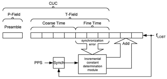
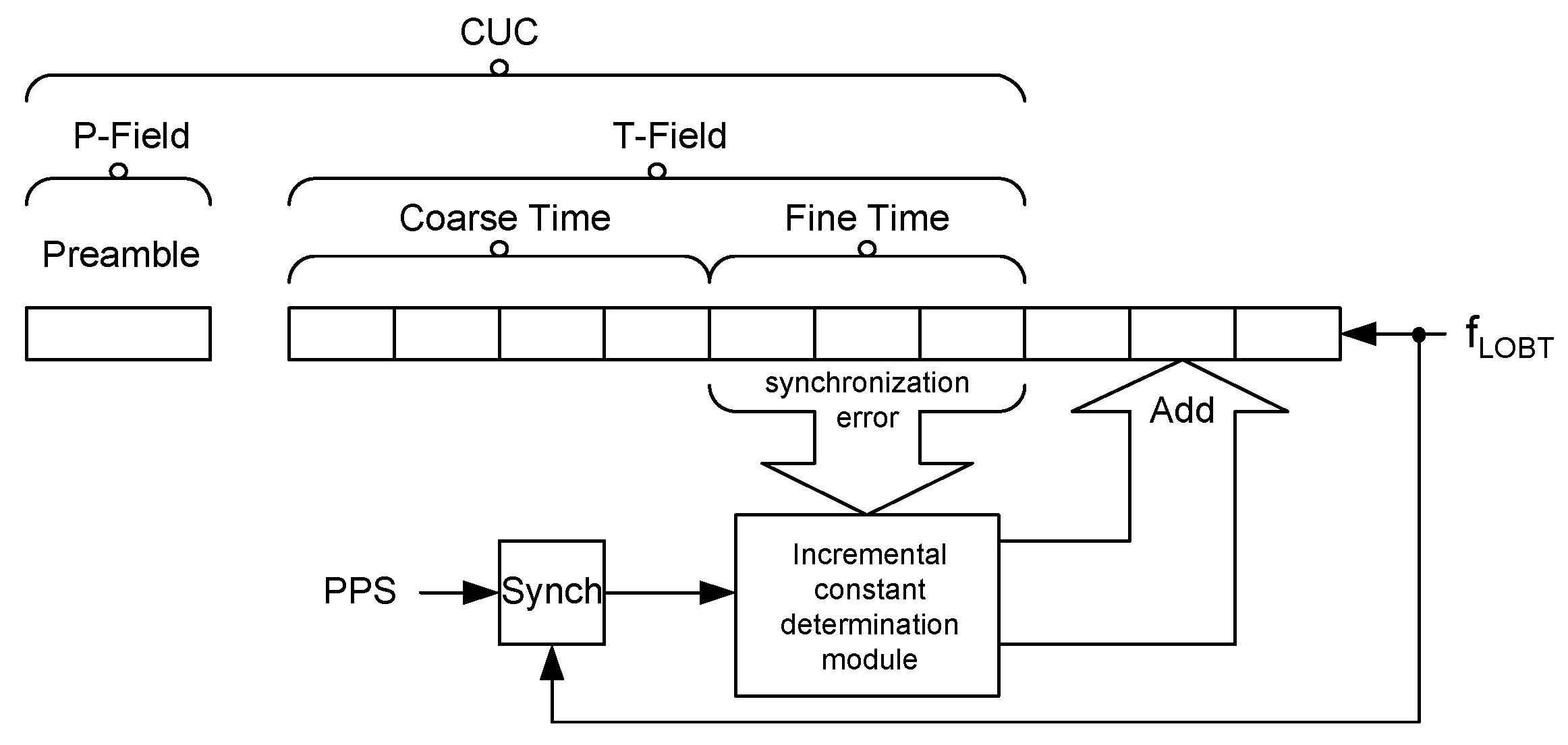
The main challenge in LOBT design is determining how to adjust the incremental constant (by how much to increase or decrease it in a given step) based on the detuning error. However, this does not change the fact that the LOBT structure can be proposed, as shown in Figure 4. It should also be emphasised that LOBTs often must also support additional functions, such as zeroing the fractional part or loading a user-specified time value.
Figure 4.
LOBT structure (Basic Timing Service), where T-Field is Time-Field and P-Field is Preamble-Field.
Naturally, some corrections are implemented via software, or the time correction values themselves are determined at a ground station (e.g., based on knowledge of the orbit) and subsequently transmitted to the onboard computer. Such approaches require the encoding of time in LOBT, which is not the subject of this work.
5. Dynamic Incremental Constant Determination Based on Detuning Error
It should be emphasised that the process of synchronising the LOBT with the PPS signal may be a multi-step process—it may require several periods of the PPS signal to obtain satisfactory tuning. Naturally, the sooner LOBT synchronises with PPS, the better. Therefore, the LOBT tuning time expressed in the number of PPS signal cycles can be a measure of the tuning speed.
Another important aspect is determining the tuning tolerance. It is expected that full alignment of the LOBT with the PPS signal will never be complete. The question arises as to when the synchronisation procedure should be initiated, or in other words, what detuning is acceptable and what is not. This means that a certain limit (tolerance) must be established for the detuning error e, which can be described as time or, more practically, a number associated with Fine Time. If the detuning error e value in a given PPS cycle is less than or equal to the tolerance value, then there is no need to initiate the synchronisation procedure in that cycle (the increment constant retains its nominal value). If the error is greater than the tolerance, then in that PPS cycle, the synchronisation procedure must be initiated. However, in many cases, a sudden change in time is not permitted, and smooth resynchronisation is required.
The key problem in the synchronisation process is the transformation of the detuning error into a change in the increment constant. Of course, different approaches to this issue are possible. It is possible to determine error threshold values for which various constants are adopted. Another approach is to determine the changes in the increment constant based on a series of dependencies which, in addition to the detuning error, may be a parameter describing the suppression of overshoots, the expected tuning time, etc. It turns out that the simplest and, at the same time, very effective solution is to determine the change in the increment constant by dividing the detuning error e by a specific constant. Note that the Fine Time value changes every 60 ns. This means that for fLOBT = 100 MHz (period is 10 ns), for one Fine Time change, there will be six cycles of the fLOBT clock, which determines that the most effective way will be to divide the detuning error by 6. For example, for fLOBT = 50 MHz (period is 20 ns), the divisor value should be 3, etc. These relationships are presented in Formulas (4).
fLOBT = 100 MHz, ∆const = e/6
fLOBT = 50 MHz, ∆const = e/3
Therefore, it can be seen that the divisor is best selected based on fLOBT. There is also the question of how to choose the tuning tolerance values. It turns out that there is no point in adopting tolerance values smaller than the divisor, because the system will not be able to synchronise errors smaller than the divisor value anyway. This means that the tolerance value can, at best, directly correspond to the divisor value.
Of course, the described problem can be approached in a more formal way. The expression can be converted into ΔN1, which will take the form (5).
Assuming that describes the controller (proportionality coefficient), it is possible to determine the dependence on the detuning error e (6)
where e(k) and e(k + 1) are the detuning errors in cycles k and k + 1 of the PPS signal.
e(k + 1) = e(k) − Ke(k) = (1 − K)e(k),
Solving this recursively yields relationship (7).
where e(0) is the initial error. Taking absolute values (8)
e
(k) = (1 − K)ke(0),
| e(k)| = |1 − K|k|e(0)|,
It is necessary to make the following assumption (in order to progressively minimise the detuning error): |1 − K| < 1, which implies 0 < K < 2.
Naturally, four cases can be distinguished here:
- K = 1, deadbeat type convergence, corresponding to the situation in which the relationship for fLOBT = 100 MHz and m = 6 indicates the value of div ≈ 6,
- 0 < K < 1, monotonic convergence,
- 1 < K < 2, oscillatory convergence,
- K ≥ 2, no convergence.
It is also possible to determine the convergence time n. Let the error tolerance be denoted as tol. Then |e(n)| ≤ tol, which can be expressed in the form (9).
|e(0)||1 − K|n ≤ tol
After some transformations, we obtain the following expression: , which leads to the following condition for n: . Thus, it can be formally expressed as (10).
It is necessary to experimentally confirm whether the indicated divisors yield the best results. The cost of implementing hardware division by specified constants in FPGAs is also an open question. For this purpose, appropriate experiments were performed (Section 6).
6. Experimental Results
In order to confirm the theoretical calculations regarding the determination of the divisor parameter in the process of correcting the detuning error of the ET counter in relation to the PPS signal, a number of experiments were performed. In a synchronised LOBT, the seconds increment should occur exactly when the rising edge of the PPS signal occurs. Therefore, a simulation was performed of desynchronising the ET counter with respect to the PPS signal in such a way that at a constant LOBT clock frequency (assumed 100 MHz), the PPS signal was artificially shifted in time, thus modelling two situations: ET is delayed relative to the PPS signal and ET is ahead of the PPS signal. Synthesis, implementation, and simulation were carried out in AMD Vivado 2022.2 with default settings. An Artix-7 device (xc7a100tcsg324) was selected. The implementation results were taken from the implementation reports. The core of the LOBT module was simulated using a dedicated testbench. A frequency of fLOBT = 100 MHz was initially assumed. Two initial desynchronisation values were assumed: 10,000 ns and a value 1000 times greater, i.e., 10,000,000 ns. This approach allows the effectiveness of the divisor selection to be determined in terms of both small and large desynchronisations. Table 1, Table 2, Table 3 and Table 4 contain the desynchronisation value in subsequent PPS signal cycles. The original maximum desynchronisation should be successively minimised with each subsequent PPS period. How this process works is strongly dependent on the selected divisor. Table 1 and Table 2 show the case in which the ET counter is ahead of the PPS signal (seconds are incremented too early), from 10,000 ns (Table 1) and 10,000,000 ns (Table 2), respectively. The results are expressed in ns.
Table 1.
Desynchronisation value (described in ns) in subsequent PPS cycles for different divisors (ET counter is ahead of PPS by 10,000 ns).
Table 2.
Desynchronisation value (described in ns) in subsequent PPS cycles for various divisors (ET counter is ahead of PPS by 10,000,000 ns).
Table 3.
Desynchronisation value (described in ns) in subsequent PPS cycles for various divisors (ET counter is delayed relative to PPS by 10,000 ns).
Table 4.
Desynchronisation value (described in ns) in subsequent PPS cycles for various divisors (ET counter is delayed relative to PPS by 10,000,000 ns).
Additionally, Table 3 and Table 4 present cases in which ET is delayed relative to the PPS signal (incrementation occurs too late), from 10,000 ns (Table 3) and 10,000,000 ns (Table 4), respectively.
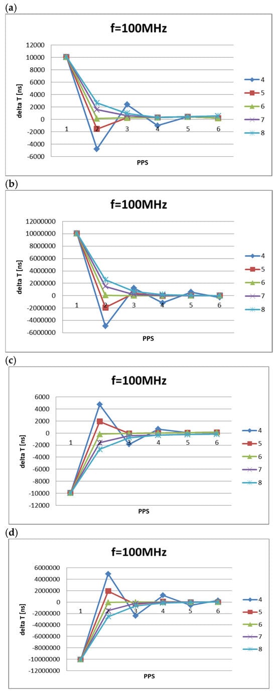
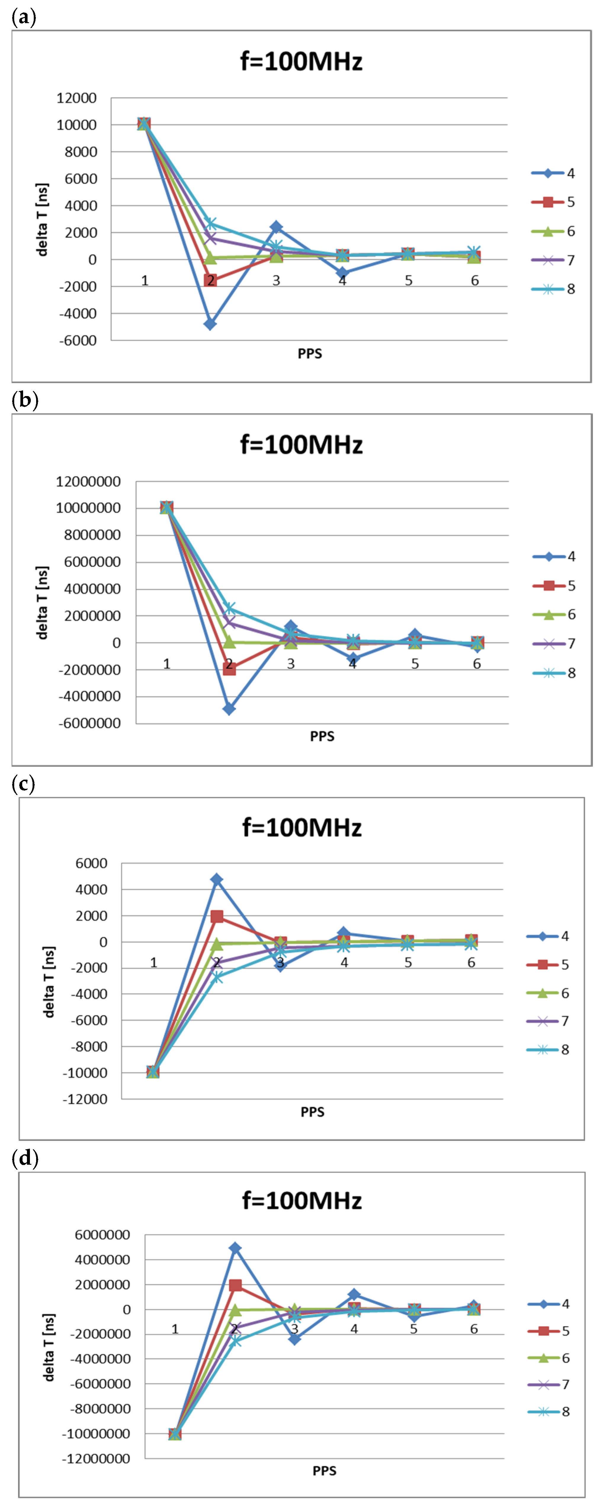
The obtained results are presented in the form of graphs in Figure 5.
Figure 5.
The value of the ET counter (100 MHz) detuning relative to the PPS signal in its subsequent cycles: the ET counter is ahead of the PPS: ET counter precedes PPS by 10,000 ns (a), ET counter precedes PPS by 10,000,000 ns (b); the ET counter is behind the PPS: ET counter is delayed relative to PPS by 10,000 ns (c), ET counter is delayed relative to PPS by 10,000,000 ns (d).
Observing the graphs in Figure 5, it is easy to see that the shapes of the family of curves in Figure 5a,b are the same (they differ only in scale). The situation is similar for Figure 5c,d. Therefore, regardless of the initial detuning value, the ET counter tuning process will be similar. It can also be seen that Figure 5c,d are practically mirror images of Figure 5a,b. Therefore, regardless of whether the ET counter lags or leads PPS, the synchronisation process depends primarily on the value of div.
Analysing the results with respect to the divisor div shows that the tuning (resynchronisation) process is most effective for a divisor of div = 6, which is consistent with theoretical calculations. For divisors smaller than 6 (div = 4 and div = 5), the detuning error sign changes with each subsequent cycle, which may indicate overshoot. For divisors greater than 6, the curve becomes increasingly smooth as the divisor increases, resulting in a significant deviation from the desired value in the initial cycles. The threshold at which the tuning process is initiated is assumed to be div*60 ns. It can be seen that, for div = 6 and a small initial detuning (10,000 ns), the circuit completes operation after just two PPS signal cycles. For other divisors, this process takes longer. It is worth noting that in the first PPS cycle, the value of ΔT deviates slightly from the theoretically expected value. This is due to the imperfection of the method used to model the PPS signal in the simulation and the need to apply the reset (rst) signal. The source of the error may be a residual error resulting from rounding the increment constant.
The question arises whether the above observations also hold true for other LOBT clock frequencies. Similar experiments were conducted for an LOBT clock frequency of fLOBT = 50 MHz. Similar simulations were performed as before, but limited to small detunings (10,000 ns), knowing that the shape of the detuning for large detunings would be the same (the difference being only in scale). Therefore, experiments were performed for two cases: the ET counter leads the PPS signal and the ET counter lags the PPS signal. The results are summarised in Table 5 and Table 6, respectively.
Table 5.
Desynchronisation value (described in ns) in subsequent PPS cycles for different divisors—ET counter is ahead of PPS by 10,000 ns (fLOBT = 50 MHz).
Table 6.
Desynchronisation value (described in ns) in subsequent PPS cycles for different divisors—the ET counter is delayed relative to PPS by 10,000 ns (fLOBT = 50 MHz).
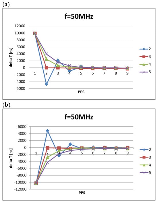
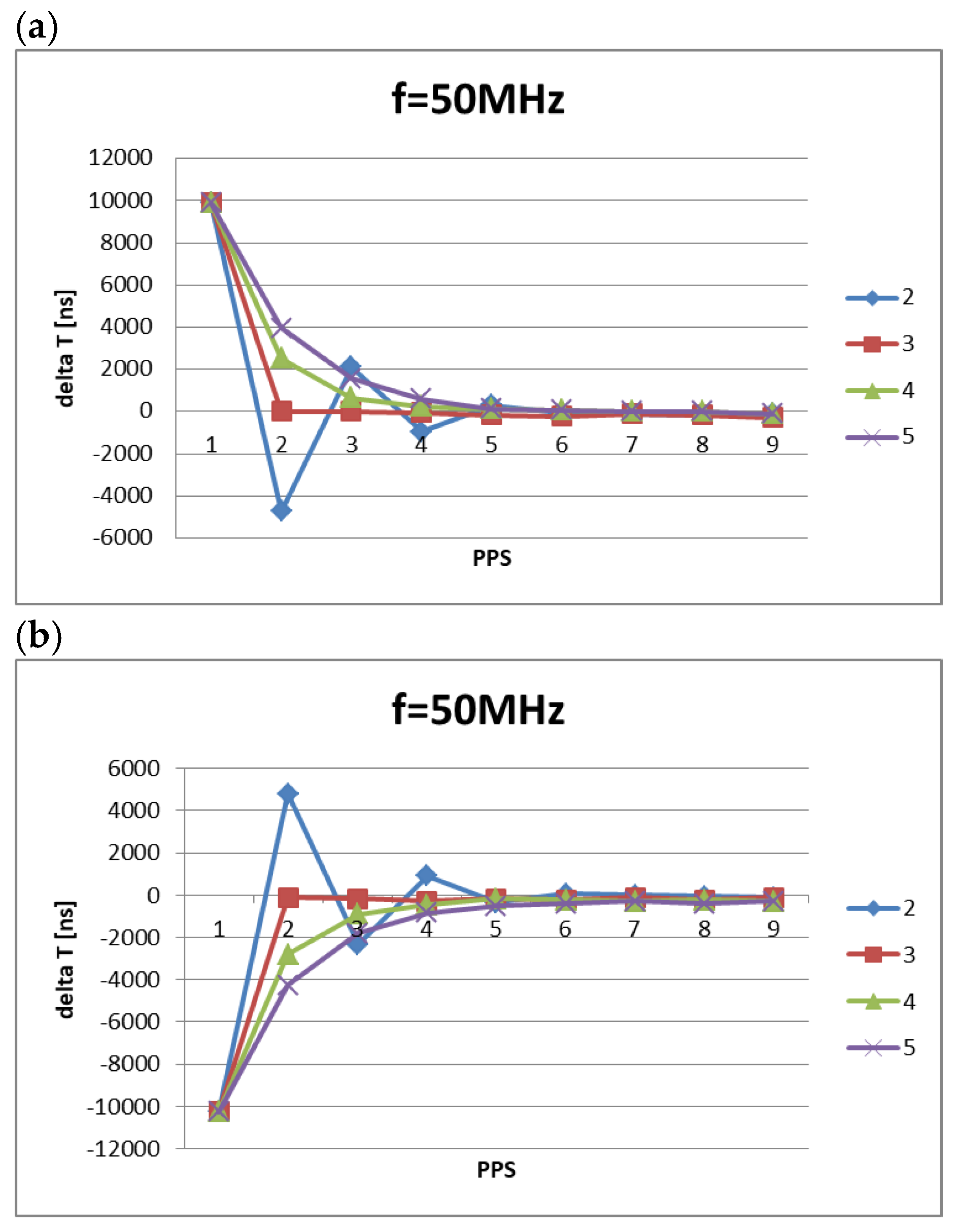
The obtained results are presented in the form of graphs in Figure 6.
Figure 6.
The value of the ET counter desynchronisation (fLOBT = 50 MHz) with respect to the PPS signal in its subsequent cycles: the ET counter is ahead of the PPS by 10,000 ns (a) and the ET counter is behind the PPS by 10,000 ns (b).
The shapes of the graphs in Figure 6 are similar to those in Figure 5. In the case considered, tuning is most effective for the divisor div = 3, which is also consistent with theoretical calculations. Similarly, for a divisor smaller than 3 (div = 2), each subsequent cycle changes the sign of the detuning value, which may indicate overshoot. Similarly, for divisors greater than 3, the curve becomes increasingly smooth as the divisor increases, resulting in a significant deviation from the desired value in the initial cycles.
In general, the obtained results are consistent with expectations. Therefore, it seems that the LOBT circuit should implement division using the optimal divisors (6 for 100 MHz and 3 for 50 MHz). This approach would ensure the most efficient tuning of the LOBT to the PPS. However, it turns out that the hardware implementation of the division operation can be very complex in some cases. Depending on the constant by which the detuning error is divided, the resulting implementations will differ in terms of the number of required logical resources and power consumption. It may also turn out that complex division will lead to violations of timing constraints in selected critical paths of the implementation. In this situation, it becomes necessary to evaluate the costs of implementing a given division in the LOBT.
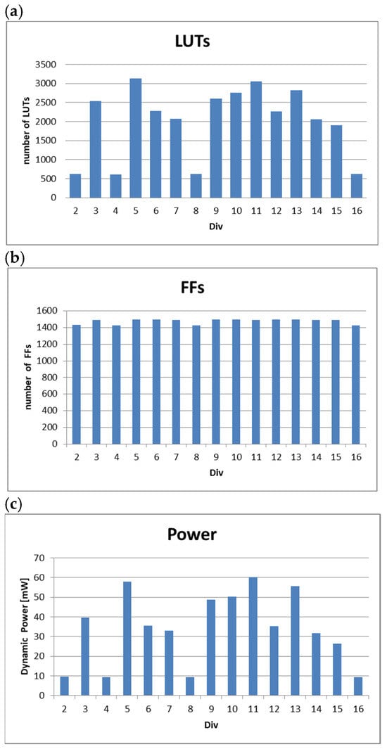
The experiments involved implementing the LOBT circuit for various divisors. An Artix-7 series FPGA was used. LOBT circuits were implemented for divisors from 2 to 16, determining the number of LUT blocks (LUTs), flip-flops (FFs), and the estimated dynamic power (Dynamic) expressed in mW. The obtained results are summarised in Table 7. Additionally, Table 7 contains results describing the dynamic properties of the obtained solutions. WNS (Worst Negative Slack), the delay value on the critical path (Data Path Delay) and the number of logical levels (Logic Levels) were determined. Based on the obtained results, graphs were constructed showing the number of LUT blocks (Figure 7a), the number of flip-flops (Figure 7b), and the power (Figure 7c).
Table 7.
Implementation results for different values of the Div divisor.
Figure 7.
Implementation results in terms of the number of LUT blocks (a), number of flip-flops (b), and dynamic power (c).
Analysing the graphs in Figure 7, it can be seen that the LOBT implementation strongly depends on the selected divisor. We can therefore conclude that the division process is dominant in this circuit. The best results are obtained when division is performed by constants that are a power of 2. Naturally, this is associated with division by a bit shift. Looking at the number of LUTs (Figure 7a), it is easy to see that in extreme cases the number of LUTs increased approximately fivefold compared to the best divisors. Also, in the case of dynamic power (Figure 7c), a more than sixfold difference is visible. In the case of flip-flops, this difference is not as large, but it is still visible that clearly better solutions are obtained for divisors 2, 4, 8, and 16.
In summary, the divisors that achieve the most efficient ET to PPS tuning (div = 6 for fLOBT = 100 MHz and div = 3 for fLOBT = 50 MHz) may prove difficult to implement. These values can lead to complex implementations and high power consumption. Therefore, a trade-off between tuning efficiency and implementation efficiency becomes necessary, which varies in each case depending on the fLOBT operating frequency of the LOBT.
7. Conclusions
A significant contribution of this article is the presentation of a hardware-oriented method for the smooth resynchronisation of an FPGA-based LOBT counter with an external PPS signal, in which the detuning error is converted into a correction of the increment constant of a fixed-frequency counter with a 48-bit fractional part so that time never moves backwards. The analysis showed that the optimal divisor of the detuning error follows directly from the ratio of the Fine Time resolution to the clock period, which was confirmed by simulation. At the same time, the implementation results revealed that this optimum is costly in hardware, so the choice of the divisor, together with the clock frequency and the tuning tolerance, is the key design decision.
The simulation results for fLOBT = 100 MHz quantify these trade-offs. With the theoretically optimal divisor div = 6 (tolerance 6 × 60 ns = 360 ns), an initial offset of 10 µs was reduced to within the tolerance after a single correction (120 ns when the ET counter was ahead of the PPS and −180 ns when it lagged behind in the second PPS cycle). An initial offset of 10 ms was reduced to approximately 66 µs after the first correction, to 720 ns (ahead) or −600 ns (behind) after the second, and to ±120 ns after the third, i.e., in the fourth PPS cycle (approximately 3 s). Once converged, the residual error remained within ±420 ns, i.e., no more than seven Fine Time LSBs (least significant bits). For div = 4 and div = 5, the per-cycle error ratio was approximately −0.5 and −0.2, respectively, so the error changed sign in every cycle (overshoot); after five corrections of a 10 ms offset, the residual error was still about ±284 µs for div = 4 and about 2.2–2.5 µs for div = 5. For div = 7 and div = 8, the convergence was monotonic, with per-cycle error ratios of approximately 0.15 and 0.26; a 10 µs offset reached the tolerance after two to three corrections, whereas a 10 ms offset was reduced to about 0.7–1.0 µs (div = 7) and about 11 µs (div = 8) after five corrections.
The same behaviour was observed for fLOBT = 50 MHz. With the optimal divisor div = 3 (tolerance 180 ns), a 10 µs offset was eliminated after a single correction (0 ns and −120 ns in the second PPS cycle), and the residual error remained within ±300 ns over the nine simulated cycles. The power-of-two divisor div = 4 required three to four corrections to reach its tolerance of 240 ns, with a residual error within ±300 ns, whereas div = 2 caused overshoot and required five corrections.
The implementation cost depends strongly on the divisor. Divisors that are powers of two (2, 4, 8, 16) required 613–618 LUTs, 1427–1430 FFs and 9.3–9.5 mW of estimated dynamic power, whereas the remaining divisors required 1903–3139 LUTs, 1491–1497 FFs and 26.3–60.2 mW, i.e., 3.1–5.1 times more LUTs, about 4–5% more FFs and 2.8–6.4 times more dynamic power. In particular, div = 6 (2274 LUTs, 1496 FFs, 35.6 mW) requires 3.7 times more LUTs and 3.8 times more dynamic power than div = 8 (617 LUTs, 1428 FFs, 9.3 mW), and div = 3 (2538 LUTs, 39.7 mW) requires 4.1 times more LUTs and 4.2 times more dynamic power than div = 4 (613 LUTs, 9.4 mW).
The choice of the divisor proves particularly crucial. The values that ensure the fastest tuning of the circuit are exceptionally cumbersome to implement. The growth of the logical structure and the increase in power consumption virtually eliminate them from the set of acceptable solutions. Therefore, a compromise between tuning efficiency and implementation efficiency becomes crucial. Divisors that are a power of two are typically chosen due to their simple implementation.
Based on these results, the following design recommendation can be formulated. For fLOBT = 100 MHz, the divisor div = 8, implemented as a 3-bit right shift, with a tuning tolerance of 8 × 60 ns = 480 ns, is recommended. It converges without overshoot, reducing the detuning error by a factor of approximately four in each PPS period. Small offsets (of the order of 10 µs) fall within the tolerance after at most three corrections (by the fourth PPS pulse, approximately 3 s), whereas large offsets (of the order of 10 ms) are reduced to about 11 µs after five corrections and, by extrapolating the observed per-cycle ratio of 0.26, below 480 ns after approximately eight corrections (about 8–9 s). At the same time, this choice saves about 1660 LUTs and about 26 mW of dynamic power compared with div = 6. The divisor div = 6 should be selected only when resynchronisation within one to three PPS periods is mandatory and its resource and power overheads are acceptable. By analogy, div = 4 (tolerance 240 ns, convergence in three to four PPS periods) is recommended for fLOBT = 50 MHz.
The study has several limitations. All synchronisation results were obtained by simulation with an ideal, jitter-free PPS signal and an ideal LOBT clock; oscillator drift, temperature effects, PPS jitter, and PPS loss and recovery were not modelled, and the first-cycle deviation results from the way the PPS and reset signals were modelled. Only two initial offsets (10 µs and 10 ms) and two clock frequencies (100 MHz and 50 MHz) were analysed, and only six (100 MHz) or nine (50 MHz) PPS cycles were simulated, so the convergence times beyond this horizon are extrapolated. The implementation results refer to a single device (Artix-7 xc7a100tcsg324) and a single tool version with default settings, and the dynamic power values are tool estimates rather than measurements.
The results presented in this work were obtained from simulations in the Vivado environment. A natural next step will be to repeat these measurements on the target hardware using a professional PPS signal generator, which the authors plan to undertake in the future.
The authors’ work was used, among other things, in the implementation of LOBT for KP Labs’ Lion Data Processing Unit (DPU).
Author Contributions
Conceptualisation, M.K. and R.C.; methodology, M.K. and R.C.; software, M.K.; validation, M.K.; formal analysis, M.K. and R.C.; investigation, M.K. and R.C.; resources, M.K.; data curation, M.K.; writing—original draft preparation, M.K. and R.C.; writing—review and editing, M.K. and R.C.; visualisation, M.K. and R.C.; supervision, M.K. and R.C.; project administration, M.K. and R.C.; funding acquisition, R.C. All authors have read and agreed to the published version of the manuscript.
Funding
This work was supported by the Polish Ministry of Science and Higher Education funding for statutory activities and the KP Labs ‘Lion DPU’ project (European Space Agency Contract No. 4000143236/23/NL/AR/ahh).
Institutional Review Board Statement
Not applicable.
Informed Consent Statement
Not applicable.
Data Availability Statement
The original contributions presented in the study are included in the article; further inquiries can be directed to the corresponding author.
Conflicts of Interest
Author Marcin Kubica was employed by the company KP Labs. Author Robert Czerwiński was employed by the company KP Labs. The authors declare no conflicts of interest.
References
- Montenbruck, O.; Kunzi, F.; De Oliveira Salgueiro, F.; Gini, F.; Limón, M. GNSS-based synchronization and monitoring of LEO-PNT onboard time. Adv. Space Res. 2025, 76, 7144–7159. [Google Scholar] [CrossRef] [Scilit]
- Hu, W.; Zhang, J.; Cheng, X. Model-Driven Clock Synchronization Algorithms for Random Loss of GNSS Time Signals in V2X Communications. Technologies 2025, 13, 273. [Google Scholar] [CrossRef] [Scilit]
- Chen, X.; Liu, C.; Fan, Y.; Guo, N. Time synchronization method based on time interval measurement. In Proceedings of the 2021 IEEE 4th Advanced Information Management, Communicates, Electronic and Automation Control Conference (IMCEC), Chongqing, China, 18–20 June 2021; pp. 2110–2114. [Google Scholar] [CrossRef] [Scilit]
- Hanasz, S.; Kuklewski, M.; Kasprowicz, G.; Bieda, M.S.; Traczyk, K. Concept of an Enhanced Accuracy Onboard Time Synchronization via Communication Link. In Proceedings of the 2020 IEEE Aerospace Conference, Big Sky, MT, USA, 7–14 March 2020; pp. 1–6. [Google Scholar] [CrossRef] [Scilit]
- Arceo-Miquel, L.; Shmaliy, Y.S.; Ibarra-Manzano, O. Optimal Synchronization of Local Clocks by GPS 1PPS Signals Using Predictive FIR Filters. IEEE Trans. Instrum. Meas. 2009, 58, 1833–1840. [Google Scholar] [CrossRef] [Scilit]
- Shmaliy, Y.S.; Ibarra-Manzano, O.; Arceo-Miquel, L. Efficient predictive steering of local clocks in GPS-based timekeeping. In Proceedings of the 2009 IEEE International Frequency Control Symposium Joint with the 22nd European Frequency and Time Forum, Besancon, France, 20–24 April 2009; pp. 727–732. [Google Scholar] [CrossRef] [Scilit]
- Kubczak, P.; Jessa, M.; Nikonowicz, J. Sliding Mode Control as an Efficient Method of Synchronization of High-Stability Oscillators with 1-pps Signals. IEEE Access 2025, 13, 217089–217096. [Google Scholar] [CrossRef] [Scilit]
- Wu, Y.; Gong, H.; Zhu, X.; Ou, G. A DPLL Method Applied to Clock Steering. IEEE Trans. Instrum. Meas. 2016, 65, 1331–1342. [Google Scholar] [CrossRef] [Scilit]
- Alecsa, B.; Onea, A. An FPGA implementation of an all digital phase locked loop for control applications. In Proceedings of the 2009 IEEE 5th International Conference on Intelligent Computer Communication and Processing, Cluj-Napoca, Romania, 27–29 August 2009; pp. 365–368. [Google Scholar] [CrossRef] [Scilit]
- Miao, X.; Hu, C.; Qiao, Y. A Novel Two Variables PID Control Algorithm in Precision Clock Disciplining System. Electronics 2024, 13, 3820. [Google Scholar] [CrossRef] [Scilit]
- Li, Q.; Wang, L.; Zhai, C.; Zhan, X. Time synchronization design based on FPGA in integrated GPS/INS system. In Proceedings of the 2009 International Conference on Mechatronics and Automation, Changchun, China, 9–12 August 2009; pp. 3769–3774. [Google Scholar] [CrossRef] [Scilit]
- Chen, Y.; Wu, H.; Tang, X.; Wu, W. Clock synchronization technology based on FPGA. In Proceedings of the 2015 IEEE International Conference on Communication Software and Networks (ICCSN), Chengdu, China, 6–7 June 2015; pp. 43–46. [Google Scholar] [CrossRef] [Scilit]
- Warda, P.; Szplet, R.; Sondej, D.; Kwiatkowski, P. Enhancing TCVCXO Stability Using the 1 PPS Signal from the GPS. In Proceedings of the 2024 11th International Workshop on Metrology for AeroSpace (MetroAeroSpace), Lublin, Poland, 3–5 June 2024; pp. 496–500. [Google Scholar] [CrossRef] [Scilit]
- Szplet, R.; Kwiatkowski, P.; Jachna, Z.; Różyc, K. An Eight-Channel 4.5-ps Precision Timestamps-Based Time Interval Counter in FPGA Chip. IEEE Trans. Instrum. Meas. 2016, 65, 2088–2100. [Google Scholar] [CrossRef] [Scilit]
- Szplet, R.; Różyc, K.; Sondej, D.; Kwiatkowski, P.; Jachna, Z.; Tyburski, J.; Ślązak, P.; Czubla, A.; Szterk, P. High-Precise Portable Three-Channel Time Interval/Frequency Counter. In Proceedings of the 2025 Joint Conference of the European Frequency and Time Forum and IEEE International Frequency Control Symposium (EFTF/IFCS), Querétaro, Mexico, 12–16 May 2025; pp. 1–3. [Google Scholar] [CrossRef] [Scilit]
- Clancy, S.C.; Shihabi, M.M.; Angkasa, K.S. Using SpaceWire time codes for spacecraft time synchronization: SpaceWire missions and applications, short paper. In Proceedings of the 2016 International SpaceWire Conference (SpaceWire), Yokohama, Japan, 24–28 October 2016; pp. 1–5. [Google Scholar] [CrossRef] [Scilit]
- Pinsard, F.; Cara, C. High-resolution time synchronization over SpaceWire links. IEEE Aerosp. Electron. Syst. Mag. 2013, 28, 14–21. [Google Scholar] [CrossRef] [Scilit]
- Sakthivel, A.; Ekergarn, J.; Hellstrom, D.; Habinc, S.; Suess, M. Spacewire time distribution protocol implementation and results. In Proceedings of the 2014 International SpaceWire Conference (SpaceWire), Vouliagmeni, Greece, 22–26 September 2014; pp. 1–7. [Google Scholar] [CrossRef] [Scilit]
- Yu, S.; He, J.; Ma, M.; Wang, S.; Peng, J.; Ni, S.; Yang, X. Autonomous Time Synchronization Link Assignment Algorithm for Low Earth Orbit Constellation. In Proceedings of the 2025 5th International Conference on Neural Networks, Information and Communication Engineering (NNICE), Guangzhou, China, 10–12 January 2025; pp. 962–966. [Google Scholar] [CrossRef] [Scilit]
- Schmidt, T.D.; Schuldt, T.; Michalak, G.; Surof, J.; Poliak, J.; Giorgi, G.; Braxmaier, C.; Meurer, M.; Günther, C. Optical Technologies for Future Global Navigation Satellite Systems. In Proceedings of the 2023 IEEE/ION Position, Location and Navigation Symposium (PLANS), Monterey, CA, USA, 24–27 April 2023; pp. 311–317. [Google Scholar] [CrossRef] [Scilit]
- Ostler, P.S.; Caffrey, M.P.; Gibelyou, D.S.; Graham, P.S.; Morgan, K.S.; Pratt, B.H.; Quinn, H.M.; Wirthlin, M.J. SRAM FPGA Reliability Analysis for Harsh Radiation Environments. IEEE Trans. Nucl. Sci. 2009, 56, 3519–3526. [Google Scholar] [CrossRef] [Scilit]
- Siegle, F.; Vladimirova, T.; Ilstad, J.; Emam, O. Mitigation of Radiation Effects in SRAM-Based FPGAs for Space Applications. ACM Comput. Surv. 2015, 47, 37. [Google Scholar] [CrossRef] [Scilit]
- Brosser, F.; Milh, E.; Geijer, V.; Larsson-Edefors, P. Assessing scrubbing techniques for Xilinx SRAM-based FPGAs in space applications. In Proceedings of the 2014 International Conference on Field-Programmable Technology (FPT), Shanghai, China, 10–12 December 2014; pp. 296–299. [Google Scholar] [CrossRef] [Scilit]
- Kim, S.; Kim, J. Low-power data representation. Electron. Lett. 2000, 36, 958–959. [Google Scholar] [CrossRef] [Scilit]
- Chi, J.C.; Lee, H.H.; Tsai, S.H.; Chi, M.C. Gate Level Multiple Supply Voltage Assignment Algorithm for Power Optimization Under Timing Constraint. IEEE Trans. Very Large Scale Integr. VLSI Syst. 2007, 15, 637–648. [Google Scholar] [CrossRef] [Scilit]
- Bezati, E.; Casale-Brunet, S.; Mattavelli, M.; Janneck, J.W. Clock-Gating of Streaming Applications for Energy Efficient Implementations on FPGAs. IEEE Trans. Comput.-Aided Des. Integr. Circuits Syst. 2017, 36, 699–703. [Google Scholar] [CrossRef] [Scilit]
- Kania, D. An Efficient Approach to Synthesis of Multi-Output Boolean Functions on PAL-based Devices. IEE Proc. Comput. Digit. Tech. 2003, 150, 143–149. [Google Scholar] [CrossRef] [Scilit] [PubMed]
- Kubica, M.; Kania, D. Graph of Outputs in the Process of Synthesis Directed at CPLDs. Mathematics 2019, 7, 1171. [Google Scholar] [CrossRef] [Scilit]
- Barkalov, A.; Titarenko, L.; Chmielewski, S. Improving characteristics of LUT-based Moore FSMs. IEEE Access 2020, 8, 155306–155318. [Google Scholar] [CrossRef] [Scilit]
- Barkalov, A.; Titarenko, L.; Mielcarek, K. Improving characteristic of LUT-based Mealy FSMs. Int. J. Appl. Math. Comput. Sci. 2020, 30, 745–759. [Google Scholar] [CrossRef] [Scilit]
- Kajstura, K.; Kania, D. Low Power Synthesis of Finite State Machines State Assignment Decomposition Algorithm. J. Circuits Syst. Comput. 2018, 27, 1850041. [Google Scholar] [CrossRef] [Scilit]
- Kania, D. Logic decomposition for PAL-based CPLDs. J. Circuits Syst. Comput. 2015, 24, 1550042. [Google Scholar] [CrossRef] [Scilit]
- Kubica, M.; Opara, A.; Kania, D. Logic Synthesis Strategy Oriented to Low Power Optimization. Appl. Sci. 2021, 11, 8797. [Google Scholar] [CrossRef] [Scilit]
- Opara, A.; Kubica, M.; Kania, D. Decomposition Approaches for Power Reduction. IEEE Access 2023, 11, 29417–29429. [Google Scholar] [CrossRef] [Scilit]
- Opara, A.; Kubica, M. Technology mapping of multi–output functions leading to the reduction of dynamic power consumption in FPGAS. Int. J. Appl. Math. Comput. Sci. 2023, 33, 267–284. [Google Scholar] [CrossRef] [Scilit]
- Kubica, M.; Czerwinski, R. Performance testing of the triple modular redundancy mitigation circuit test environment implementation in field programmable gate array structures. Appl. Sci. 2024, 14, 8604. [Google Scholar] [CrossRef] [Scilit]
- Kubica, M.; Czerwinski, R. Error mitigation methods for FSM using triple modular redundancy. Appl. Sci. 2025, 15, 6726. [Google Scholar] [CrossRef] [Scilit]
- Zheng, S.; You, H.; He, G.; Wang, Q.; Si, T.; Jiang, J.; Jin, J.; Jing, N. A Rapid Scrubbing Technique for SEU Mitigation on SRAM-Based FPGAs. In Proceedings of the 2019 IEEE International Symposium on Circuits and Systems (ISCAS), Sapporo, Japan, 26–29 May 2019; pp. 1–5. [Google Scholar] [CrossRef] [Scilit]
- Kumar, M.; Digdarsini, D.; Misra, N.; Ram, T.V.S. SEU mitigation of Rad-Tolerant Xilinx FPGA using external scrubbing for geostationary mission. In Proceedings of the 2017 4th International Conference on Signal Processing and Integrated Networks (SPIN), Noida, India, 2–3 February 2017; pp. 414–418. [Google Scholar] [CrossRef] [Scilit]
- Ruano, Ó.; García-Herrero, F.; Aranda, L.A.; Sánchez-Macián, A.; Rodriguez, L.; Maestro, J.A. Fault Injection Emulation for Systems in FPGAs: Tools, Techniques and Methodology, a Tutorial. Sensors 2021, 21, 1392. [Google Scholar] [CrossRef] [Scilit] [PubMed]
- He, W.; Wang, Y.; Xing, K.; Chen, L. SEU readback interval strategy of SRAM-based FPGA for space application. In Proceedings of the 2011 IEEE International Conference on Computer Science and Automation Engineering, Shanghai, China, 10–12 June 2011; pp. 238–241. [Google Scholar] [CrossRef] [Scilit]
- Hamming, R.W. Error detecting and error correcting codes. Bell Syst. Tech. J. 1950, 29, 147–160. [Google Scholar] [CrossRef] [Scilit]
- Reed, I.S.; Solomon, G. Polynomial Codes Over Certain Finite Fields. J. Soc. Ind. Appl. Math. 1960, 8, 300–304. [Google Scholar] [CrossRef] [Scilit]
- The Consultative Committee for Space Data Systems. Time Code Formats; CCSDS 301.0-B-4; The Consultative Committee for Space Data Systems: Reston, VA, USA, 2010; Available online: https://ccsds.org/publications/allpubs/entry/3147/ (accessed on 1 September 2025).
- GRLIB IP Frontgrade Gaisler. Core User’s Manual, 2nd ed.; Frontgrade Gaisler: Gothenburg, Sweden, 2025; Available online: https://download.gaisler.com/products/GRLIB/doc/grip.pdf (accessed on 16 December 2025).
- European Space Agency. CCSDS Unsegmented Code (CUC) & CCSDS Time Manager (CTM) Synthesizable VHDL IP Core; D/TOS-ESM/SH/154; Issue 0.2; European Space Agency: Paris, France, 2003. Available online: http://microelectronics.esa.int/core/ipdoc/CTM-0-2.pdf (accessed on 23 November 2025).

Disclaimer/Publisher’s Note: The statements, opinions and data contained in all publications are solely those of the individual author(s) and contributor(s) and not of MDPI and/or the editor(s). MDPI and/or the editor(s) disclaim responsibility for any injury to people or property resulting from any ideas, methods, instructions or products referred to in the content. |
© 2026 by the authors. Licensee MDPI, Basel, Switzerland. This article is an open access article distributed under the terms and conditions of the Creative Commons Attribution (CC BY) license.