


Abstract
Conventional load-carrying practices in hilly and low-resource regions, such as Doko and head-straps, put substantial axial load pressures on the spine, resulting in chronic musculoskeletal discomfort. This research presents LoCaDe-Exo, a CFRP-based wearable load-carrying assistive device designed to redistribute payload forces through a terrain-adaptive ground support system. The study utilized finite element analysis (FEA), multi-body dynamics (MBD), modal analysis, and a comparative screening life-cycle carbon assessment. At 400 N, the CFRP frame exhibited a maximum stress of 94.8 Mpa, a displacement of 1.92 mm, and a factor of safety of 3.2. Structural refinement, however, reduced the frame mass by ≈18% to 4.1 kg. Similarly, the MBD evaluations predicted a ground-support force of 269.3 N, indicating a 71% ground load transfer. Additionally, the L5/S1 compression decreased from 828.5 to 548.5 N, representing a 33% reduction. The natural frequencies (14.2, 22.5, 31.8 Hz) were well separated, suggesting a low likelihood of direct resonance between the structure and the operating conditions. Over 5 years, the CFRP configuration produced the lowest estimated life-cycle carbon footprint at 420.7 kg CO2e. These findings demonstrate the feasibility of the LoCaDe-Exo device as a potential sustainable option for heavy load-carriage in rugged, high-altitude conditions. However, the results are numerical/simulation-based. The findings contribute to SDGs 3, 8, 9, 12 and 13. Future studies will focus on an experimental prototype and human-subject validation.
1. Introduction
Background and Motivation
Manual load carriage remains a critical component of livelihood and logistical activity in mountainous and infrastructure-constrained regions such as the Himalayas, the Andes, and the Ethiopian highlands. In these rural, low-resourced settings, the conveyance of essential goods including agricultural produce, food supplies, animal dung, domestic and commercial items, and medical supplies relies almost entirely on human carriers [1,2,3,4]. In contrast to flatland logistics, porters in these regions must navigate steep slopes (≥25 degrees), uneven, rocky surfaces, and narrow pathways covering long distances. These conditions frequently limit the use of motorized transport and, during certain seasons, even restrict the deployment of pack animals [3,5].
Traditional load-carrying systems, such as the Doko (a shoulder-supported wicker basket) and head-supported tumpline systems, have been employed for centuries and remain deeply embedded in the cultural practices of these populations [2,6]. Despite their cultural significance, these methods impose substantial physiological strain on the head, shoulder, and vertebrae due to insufficient load distribution across the musculoskeletal system [7,8]. Consequently, the physical demands associated with heavy and repetitive load carriage in these contexts are shaped not only by the payload mass but also by walking speed, terrain inclination, load position, distance travelled, and the biomechanical interaction between the load-carriage apparatus and the human body.
Figure 1 illustrates a woman in the Himalayas wearing a Doko basket. Rural dwellers usually use Dokos to carry goods in Nepal, Bhutan, and Northern India’s mountainous areas, such as Sikkim and Uttarakhand states [1,6].
Figure 1.
A woman carrying a load in a mountainous terrain.
Biomechanical studies consistently demonstrate that external backpack loads substantially alter the mechanical and energetic demands during walking [9,10,11]. Looney et al. [9] showed that increasing backpack load significantly elevates cardiometabolic responses, including oxygen consumption and metabolic rate during walking.
Controlled experimental research shows that carrying backpack loads increases mechanical work and metabolic energy expenditure, with the increase in metabolic rate generally scaling with the magnitude of the carried load [12,13]. A 2025 study by Sturdy et al. [12] posited that heavier body-mass-normalized backpack loads increase joint moments and muscle excitations across different slopes, indicating higher mechanical work. Similarly, a biomechanical analysis by Matur et al. [13] found that backpack load carriage increases EMG activity and modifies gait mechanics, confirming increased mechanical and energetic demands.
These effects are particularly relevant where load carriage is performed repeatedly and over difficult terrain. Additionally, the studies indicate that the consequences of load carriage extend beyond the additional mass itself.
Several technological approaches have therefore been investigated to reduce the physical burden associated with load carriage. Conventional backpacks and improved load-distribution systems can redistribute forces between the shoulders and the pelvis, thereby modifying the mechanical interaction between the load and wearer. Recent experimental studies have demonstrated that the dynamic and suspended-load mechanisms can attenuate inertial load oscillations and reduce the energetic demands of walking [8,14,15]. For instance, work by Ju et al. [14] on suspended-load backpack systems incorporating constant-force cam spring mechanisms has shown 84.7% reductions in peak vertical accelerative forces and 10.58% measurable decreases in metabolic energy expenditure during controlled locomotion trials, highlighting the potential of compliant load-transfer mechanisms to reduce physical strain. Complementary studies by Huang et al. [8] on suspended-load backpacks experimentally reported 15.25 ± 4.21% and 8.81 ± 2.46% reductions in metabolic expenditure and load-related adaptations. Similarly, Li et al. [16] reported that lower-limb augmentation exoskeletons designed for carrying loads can help to reduce perceived discomfort and modify activation patterns under extreme load conditions. However, there is an observed increase in activation of some muscle groups due to constraints in the human and the system.
Collectively, these findings indicate that dynamic and suspended-load systems can reduce metabolic cost and lower-limb mechanical demands. However, they introduce trade-offs such as increased shoulder loading, structural inflexibility, or stability-related considerations that must be addressed in future designs.
Exoskeleton-based systems provide an alternative load-carriage strategy by introducing an external structural or actuated pathway through which part of the carried mass can be redirected away from the musculoskeletal systems [17,18,19,20,21]. However, their effectiveness is fundamentally dependent on the quality of human–robot interaction, including alignment, impedance, and the dynamic coupling between the user and the device. Experimental evaluations of lower-body load-carrying exoskeletons have shown that when the device mass, inertia, and kinematic compatibility are not adequately controlled, the addition of an exoskeleton can increase muscle activation and elevate physiological burden during walking [10,22,23]. Conversely, appropriately designed autonomous and whole-leg exoskeletons have demonstrated reductions in metabolic expenditure during walking under controlled experimental conditions [24,25].
These findings indicate that the potential of an assistive device cannot be inferred solely from its ability to support an external load. Nevertheless, device mass, load-path, mechanical impedance, joint interaction, gait compatibility, and terrain conditions must also be considered.
Wheeled load-carriage systems provide an alternative means of reducing the direct mechanical burden on the human body because part of the payload is ground-supported [26]. However, their applicability in mountainous and low-resourced environments, is constrained by terrain geometry. Conventional wheeled assistive devices [26,27] may perform poorly on narrow, uneven or steep paths and may require sufficient manoeuvring space that is unavailable in many rural settings. Consequently, the design challenge is not simply to transfer load from the human body to wheel-supported structure, but to achieve such transfer while retaining sufficient mobility and stability for irregular terrain.
Existing systems generally address either human load distribution, mechanical assistance, or terrain mobility. However, comparatively limited work has been done that integrates wearable load support, ground-directed load transfer, terrain adaptability, structural lightweighting and sustainability within one design framework.
An integrated evaluation of such a system also requires more than a single structural analysis. Finite element analysis provides and means of examining stresses, deformations and structural safety under prescribed loading conditions [28]. Multi-body dynamics can be used to computationally model interactions among the device, payload and human body during locomotion [29,30]. Modal analysis can further identify the natural frequencies of the structure and assess whether its dynamic characteristics are compatible with the intended walking conditions [31].
Material selection must also consider both structural performance and environmental impacts. This is because high-performance materials can involve substantial manufacturing energy requirements and carbon emissions.
The importance of computational verification is particularly relevant to the structural and biomechanical simulations. Mesh convergence should be demonstrated for the quantities used to provide additional principal conclusions. Additionally, simplified analytical or previously verified solutions can provide additional checks on numerical implementation [28,32,33]. Such a verification establishes whether the computational procedure adequately solves the intended mathematical problem. However, it does not by itself, establish that the model accurately represents human-device behaviour.
Against this background the present study conceived by the authors develops and numerically evaluates a terrain adaptive and sustainable load-carrying device (LoCaDe-Exo) intended for hilly-low-resourced environments.
The proposed system conceived by the authors integrates a Structural backbone based on a Carbon Reinforce Fibre Polymer (CFRP), an Ergonomic interface, and a terrain adaptive system (TASS). The Terrain Adaptive support system (TASS) incorporates telescopic support rods, spring-damper elements, an active suspension hinge (ASH) and multidirectional wheels (OMDW). The telescopic rods provide a load-transfer pathway towards the ground, while the suspension components are intended to attenuate transient forces associated with changes in terrain and walking dynamics.
The study evaluates the structural integrity of the system using FEA [28] under design and overload conditions, examines the load transfer and human biomechanical loading using MBD [29,30], and its modal characteristics [31]. Additionally, computational verification through mesh convergence and other numerical checks is incorporated to establish the reliability of the numerical implementation [32,33]. Furthermore, the study evaluates the comparative life-cycle carbon implications of alternative structural materials, including the robustness of the sustainability conclusions through sensitivity analysis. The overall objective is to provide a numerical blueprint for a new class of terrain-adaptive and sustainable load-carrying assistive devices for hilly environments.
From a sustainability perspective, the proposed approach considers material and life-cycle efficiency alongside human-ergonomic and operational considerations. The use of CFRP is motivated by its high strength-to-weight ratio and resistance to corrosion; although its manufacturing stage can have a higher initial energy footprint than some alternative materials [34,35,36,37]. Its durability under environmental exposure can also contribute to extended product life and reduced replacement frequency [35,36,38].
Accordingly, the study considers sustainability not Soley as a measure of material selection but in relation to structural efficiency, human load reduction, operational characteristics, and life-cycle carbon performance. These considerations provide the basis for the subsequent sustainability assessment and sensitivity analysis. Figure illustrates the proposed load-carrying device.
Figure 2 illustrates a detailed 3D representation of the proposed innovative sustainable wearable device.
Figure 2.
Proposed novel sustainable wearable device (a) with load (b) without load.
2. Materials and Methods
2.1. System Architecture and Design Requirements
The system was developed using an open-source CAD software FreeCAD 1.0.0 (https://www.freecad.org), which is organized into three primary sub-assemblies: the Structural Backbone, the Ergonomic Interface and the Terrain-Adaptive Support System. This modular design allows the device to be tailored to various body types and facilitates repairs in remote, hilly environments.
The architecture was designed around the principle that a portion of the payload should be re-directed from the wearers musculoskeletal system to a ground supported pathway while preserving sufficient freedom of movement for walking on narrow and uneven terrain.
2.1.1. The Structural Backbone (Carbon-Fibre Monocoque)
The central frame (structural backbone), as shown in Figure 3, is the primary load-bearing element (Structural Backbone). To achieve high stiffness while maintaining a “sustainable” low weight, a Carbon Fibre Reinforced Polymer (CFRP) layup is used. The frame features a contoured “S-curve” that mimics the natural curvature of the human spine (lordosis and kyphosis) [39].
Figure 3.
(a) Exploded view of the LoCaDe-Exo divided into three primary sub-assemblies. Ergonomic Interface (1&2): 1—Shoulder/Load lifter straps, 2—Hi, Terrain-Adaptive Support System (3,4,5&6): 3—Telescopic support rod, 4—Omni-wheels, 5—Coil-spring damper, 6—Active suspension hinge, Structural Backbone (7,8,9&10): 7—S-curve CRF support, 8—Load straps, 9—load, 10—Main frame. (b) Engineering schematics of the LoCaDe-Exo with dimensions in mm.
This allows the distribution of residual load over a large surface area to prevent pressure sores that may be localized at the back of the user. Because CFRP is an orthotropic composite material, its numerical representation requires specification of the material properties in the principal material directions. This includes where a laminate representation is used, the corresponding ply orientations and thickness (specified in the FEA section).
2.1.2. Ergonomic Interface
The ergonomic interface connects the structural system to the wearer. The system features a breathable mesh, shoulder/load-lifter straps and a hip belt.
The interface is intended to distribute the residual forces acting on the wearer while maintaining sufficient clearance for normal movement of the upper body.
The shoulder/lifter straps provide an attachment pathway between the wearer and the upper section of the structural frame. The wide, padded, hip belt serves as the primary attachment point, ensuring the device moves in sync with the user’s centre of mass (CoM). The 3D spacer mesh allows a about 2 cm air gap located between the user’s back and the CFRP frame. This allows for passive cooling and the reduction of thermal stress which significantly influence user fatigue in tropical hilly areas. Figure 4 illustrates the structure of the ergonomic interface.
Figure 4.
Ergonomic mesh harness.
In the numerical model these interfaces are represented through simplified boundary/contact conditions.
2.1.3. Terrain Adaptive Support System (TASS)
The Active Suspension Hinge (ASH)
The ASH is the brain of the LoCaDe-Exo device system and is located between the main CFRP frame and the lower support struts. The system incorporates a high-travel coil spring and a damper which is fluid-filled. When a user is descending a steep hill, there is a compression of the ASH to absorb the peak dynamic force (Fpeak = 2.5 ∗ body weight) [40]. This phenomenon therefore protects the device user (mountain porters) from sustaining injuries to the knee and lower back, typically caused by the jarring effect during the “heel strike” phase of walking.
Telescopic Ground-Support Rods
In contrast to conventional backpacks, the terrain adaptive load-carrying device (LoCaDe-Exo) could extend its spring-loaded telescopic ground-support rods to the ground. This is because the length of the spring-loaded locking system can be dynamically adjusted, helping device users navigate uneven, rocky steps commonly experienced on hilly trails.
In creating a secondary load path, the telescopic rods transfer a substantial part of the payload directly to the ground, rather that absorbing them fully through the user’s pelvis and legs.
Omni-Directional Mobility System
Attached to the telescopic ground-support rod rods are omnidirectional wheels designed in a Mecanum style [27]. In narrow mountain passes, turning a wide load is dangerous. The omni-wheels allow the device to slide or manoeuvre laterally or pivot on a dime, providing the user with zero-turn capability. The wheels are designed with a high-friction rubber tread to maintain grip on wet shale, mud, and loose gravel (surface adaptation). Figure 5 illustrates the Terrain Adaptive System, which includes the Active Suspension Hinge (ASH), the Telescopic Ground Support Rods and the Omni-wheel system (OMDW).
Figure 5.
(a) 3D view of the Terrain Adaptive Support System, (b) Orthographic view of the Terrain Adaptive Support System. 3. Telescopic Support Rods, 4. Omnidirectional Mobility System, 5. Coil Spring Damper, 6. Active Suspension.
2.2. Research Design and Workflow
The study adopted an integrated numerical approach and evaluation framework for the design concept and assessment of the LoCaDe-Exo. Additionally, the research relied on field-field derived information, engineering design principles and computational modelling to establish and evaluate the proposed system. The workflow was structured to progressively translate the identified load-carriage requirements into a computationally defined device. Additionally, device’s structural, biomechanical, mechanical, and sustainability performance was assessed using complementary numerical methods.
The workflow comprised seven interconnected phases. These include conceptual design, mathematical modelling, finite element analysis, structural refinement and optimization, multi-body dynamics analysis sustainability assessment and sensitivity analysis. Nevertheless, the workflow represents a sequential but interconnected numerical evaluation process in which the output of one modelling stage provides inputs for the subsequent stage.
The approach enabled the proposed device to be evaluated from multiple complementary perspectives without claiming experimental confirmations of its performance. Figure 6 provides the entire research and design workflow.
Figure 6.
Research and design workflow.
2.3. Mathematical Modelling
2.3.1. Kinematic Equations: 5-Link Chain Gait Simulation
To analyze the interaction between the user and the wearable device, the system is modelled as a 5-link planar bipedal chain. The links represent the (1) Shank, (2) Thigh, (3) Pelvis/Torso, and the two external links of the device: (4) Upper Frame and (5) Telescopic Support Rods.
The kinematic formulation was used to determine the position and orientation of the payload relative to the ground reference frame as a function of the joint variables and link dimensions.
(refer to annexure link for results of PL, Fgorund & Fdamp).
Using the Denavit-Hartenberg (D-H) convention, the position of the load (PL) relative to the ground contact point (G) is defined by [41,42]:
where:
PL—is the position of the load relative to the ground point.
Li—represents the length of each anatomical and mechanical link.
θj—represents the joint angles (hip/device hinge, knee and ankle), and
L5—The telescopic link with a time-varying parameter [L5(t)]. This adjusts based on the terrain profile.
2.3.2. Force Transmission Model
The primary goal of the device is to divert the gravitational force of the load (Fload) away from the human musculoskeletal system and toward the ground via the support rods. The ground support force was therefore represented as a function of the gravitational component of the payload force and the force generated by the spring-damper mechanism.
On a slope with an angle θ, the normal force transmitted to the ground (Fground) is modelled as [43,44,45]:
where: Fload = m × g (Mass of payload × gravity)–normal load transferred to the ground.
Fground = (Fload. cos θ) − Fdamp
θ is the inclination of the hilly terrain and.
Fdamp is the internal resistive force of the Active Suspension Hinge, modelled as a function of the compression velocity () and displacement (x) [43,44,45]:
where c is the damping coefficient, and k is the spring constant.
This model shows that as the slope increases, the efficiency of the ground-support rods decreases, thereby transferring more load to the harness—a vital element in the simulation’s boundary conditions.
2.3.3. Load Transfer Efficiency (LTE)
The aim of the load-transfer efficiency (LTE) ground-transmission efficiency (EGT) is to quantify the proportion of the external load that is successfully redirected through the wearable structure to the ground, thereby reducing the mechanical burden on the user’s musculoskeletal system.
LTE is therefore defined as the ratio of the axial force transmitted through the support structure to a reference load expressed as a percentage (%) [43].
where:
LTE (EGT)—load-transfer efficiency (LTE) ground-transmission efficiency (EGT).
Fground—Axial force transmitted through the support structure to the ground.
Freference—Is the reference load (the nominal external load applied directly to the user without resistance).
Figure 7 illustrates a free-body diagram (FBD) of the vectors for Fload, Fground and the resultant reaction forces at the user’s shoulders and hips.
Figure 7.
Free-body diagram (FBD) of the vectors for Fload, Fground & the resultant reaction forces at the user’s shoulders & hip.
2.4. Terrain Adaptive Control
The system design incorporates a proportional-integral-derivative (PID) control loop that adjusts the length of the telescopic rods (L5). This ensures that the error (e) between the desired frame orientation (vertical) and the actual orientation (measured by the inertial measurement unit) is reduced.
The control signal u(t) is defined as [46]:
where;
u(t) = control signal.
e(t) = difference between desired and actual rod position.
Kp = proportionality gain-(gives an immediate response to sudden step height changes).
Ki = integral gain (eliminates steady-state error and ensures that the frame stays level during long uphill climbing).
Kd = derivative gain (dampens the system to hinder any overshoot or bouncing when the omni-wheels strike a rock).
This mathematical analysis ensures that consequent FEA and MBD are well situated in realistic mechanical constrains. Figure 8 shows the analysis of the control law and the PID logic for levelling the load. The terrain adaptive design/control parameters are provided in Table 1.
Figure 8.
PID control load levelling.
Table 1.
Terrain Adaptive Design/Control Parameters.
2.5. Finite Element Analysis FEA
2.5.1. FEA Model and Material Definition
A finite element analysis (FEA) was performed using FreeCAD 1.0.0 FEM workbench 2026 on a high-fidelity 3D mesh to evaluate the structural response of the LoCaDe-Exo CFRP frame under prescribed loading conditions.
The frame was modelled as a CFRP with linear-elastic orthotropic properties. A parabolic tetrahedral mesh was employed applying a local refinement of 0.5 mm element size at both the ASH and the telescopic rod attachment. This indicates the points to accurately capture stress gradients.
The material coordinate system is aligned with the principal fibre direction along the structural members such that, the longitudinal modulus (E1) = 135 GPa, the transverse in-plane modulus (E2) = 10 GPa, and the through-thickness modulus (E3) = 10 GPa.
To mimic real-world conditions (ranging from light to heavy loads), three different load scenarios were applied vertically to the primary load plate. These include 200 N (20 kg reference design load) and 400 N (40 kg design-standard load for hilly porters). Additionally, a 500 N (50 kg) was applied as an overload condition to assess the structural limits and safety margin of the system.
The material models, the relevant directional elastic properties, density and strength parameters are provided in Table 2. The metallic components were represented using the material constitutive models.
Table 2.
Summary of material properties and constituent assumptions.
2.5.2. Boundary Conditions
The wearable nature of the LoCaDe-Exo device was replicated in the FEA environment. To replicate the resistance of the torso of the user, the shoulder straps mount and the lumbar belt were modelled as fixed supports. Similarly, the bottom of the rods, where the omnidirectional wheels are attached, was modelled as compression only supports. This enables the rods to withstand the vertical load while simulating the ground-contact interface. The force of gravity constant (g = 9.812 m/s2) was applied to the entire assembly.
2.6. Mesh Generation and Convergence
The FEA model for the device was discretized using a 3D tetrahedral mesh. A progressive mesh refinement procedure was utilized to establish an appropriate balance between numerical accuracy and computational cost. The mesh was refined from a characteristic element size of 5.0 mm to 3.0 mm and finally to 2.0 mm. This resulted in 268,400, 624,800 and 1,243,600 elements respectively, and corresponds to node counts of 435,700, 981,500 and 1,924,800.
Maximum von Mises stress and maximum total deformation were used as the principal convergence quantities. Refinement from the coarse to the medium mesh resulted in changes of 9.95% in maximum von Mises stress and 4.42% in maximum deformation. A further refinement from the medium to the fine mesh reduced the changes to 3.95% and 1.59% respectively.
Having both values below the convergence criterion of 5%, the 2.0 mm fine mesh was selected as the production mesh for the subsequent FEA simulations. The 2.0 mm fine mesh comprises of 1,243,600 elements and 1,924,800 nodes.
Numerical verification was conducted utilizing a mesh convergence analysis. The mesh-convergence analysis established that the principal structural outputs were materially dependent on further mesh refinement. Using the convergence formulae with preceding mesh as reference [47]
where; %ΔQ—Percentage mesh convergence; Qcurrent—Current mesh convergence values for stress.
Qprevious—Previous mesh convergence values for deformation; Δσ—Change in stress (Δσ ≤ 5%);
Δµ—Change in deformation (Δµ ≤ 5%).
2.7. Multi-Body Dynamics (MBD)
While FEA assesses the structural integrity of the frame, Multi-Body Dynamics (MBD) evaluates the interaction of the device with the carried payload and the virtual human body during movement [29,30]. The purpose of the MBD analysis was to determine how the terrain adaptive mechanism modifies the load-path between the payload, the human body and the ground. Additionally, it will estimate the corresponding effect on the predicted compressive loading at the L5/S1 lumbar joint.
The MBD model represented the human body as a linked multi-segment mechanical system coupled to the LoCaDe-Exo device.
This approach is consistent with established biomechanical modelling methods in which the human body is represented by rigid or articulated segments connected through anatomical joint centres and used to estimate joint forces and moments during movement [48].
The LoCaDe-Exo device was represented as a coupled mechanical system. This comprises the payload, S-curve CFRP structural frame, active suspension hinge (ASH), telescopic support rods, spring damper assembly and omni-wheeled ground-support mechanism. The configuration conforms to the three principal functional sub-systems described in the design section namely the structural backbone, ergonomic interface and terrain-adaptive support system (TASS).
Human-Device Interface–Connection and Joint Definitions
The human-device interaction was modelled as mechanical connections selected according to the intended physical function of each component. The shoulder/load—lifter straps and lumbar belt were modelled as attachment interfaces between the virtual human and the wearable frame. These interfaces were represented as fixed attachments in the MBD model. However, the corresponding attachment points on the frame remained coincident with the prescribed locations on the virtual human during the simulation. This representation assumes that the harness transfers the externally applied payload to the human body without introducing independent rigid-body motion at the attachment points.
The main CFRP frame was modelled as a rigid structural body relative to the MBD degrees of freedom DOF). Nevertheless, its motion governed by the connections to the human interface, suspension mechanism and support system.
The active suspension hinge (ASH) was represented by a revolute joint, permitting rotational motion about the hinge axis while constraining the remaining relative translational and rotational DOF.
The joint was used to represent the principal articulated connection between the CFRP frame and the terrain-adaptive support assembly.
The telescopic support rods were modelled as translational/prismatic connections along their longitudinal axes to reproduce their extension and compression behaviour. Their axial response was coupled to the spring-damper element used in the terrain-adaptive support system.
The spring spring-damper therefore provided compliant behaviour in the support path. This allowed relative axial displacement while generating a restoring and damping force according to the prescribed mechanical parameters.
The wheel assemblies connected to the lower ends of the telescopic support rods through appropriate rotational joints. This enabled the wheels to rotate about their respective axle axes during forward motion. Additionally, the wheel-ground interaction was subsequently governed by the prescribed contact and friction conditions in the terrain simulation.
The MBD technique was used to simulate the gait of a Virtual Human. A 50th-percentile female anthropometric geometry was used to represent the virtual human with a prescribed body mass of 75 kg for the simulation. However, the percentile designation refers to anthropometric geometry rather than body mass.
The virtual human was equipped with the wearable device (LoCaDe-Exo) having a payload of 400 N.
To replicate the usual brisk pace for a porter, a constant walking speed of 1.2 m/s was maintained. Additionally, the analysis imitated a dry, rocky terrain at 20° inclination using a friction coefficient (µ) of 0.6. The analysis particularly tracked the vertical and longitudinal forces at the omnidirectional wheels in measuring the ground reaction force (GRF) [49].
In the MBD analysis, the stature of the 50th percentile female virtual human model was estimated at 165 cm. Segment masses were derived by scaling established female body-segment mass fractions to the prescribed 75 kg body mass. The model comprised head, bilateral upper arm, forearm, hand, thigh, shank and foot segments. The L5/S1 articulation was explicitly represented to permit evaluation of predicted lumbar compressive loading. Major limb articulations were represented using the anatomically appropriate rotational DOF.
The female mass fractions are provided as 6.68% for the head/neck, 42.57% for the trunk, 2.55% for each upper arm, 1.38% for each forearm, 0.56% for each hand, 14.78% for each thigh, 4.81% for each shank and 1.29% for each foot. These parameters align with the adjusted female body-segment data reported by De Leva [50]. The anthropometric and biomechanical properties details of the virtual human model are provided in Table 3.
Table 3.
Anthropometric and biomechanical properties of the virtual human model.
Table 4 provides a summary of the principal connections in the MBD model.
Table 4.
Summary of principal MBD connections.
2.8. Global Force Equilibrium and Load Consistency Check
Global force equilibrium and simplified load consistency checks were used to assess whether the numerical response was physically consistent with the applied loading. The governing equation for the global force equilibrium is represented by [43,51]
where;
WP ∗ dp,H = payload weight and payload offset distance (400 N & 0.22 m).
FStrut (Fhuman) = harness/user interface force (120 N).
LMovement = effective moment arm (perpendicular lever are from the pivot-Hip (hinge) to the line of action (0.733 m).
The moment balance analysis confirms that an effective moment arm LMovement = 0.733 m maintains the intended 30%/70% load split between the device wearer’s harness and the ground-directed trailing column.
The 400 N loading condition was adopted as a nominal rounded design load. This corresponds approximately to the gravitational force associated with a 40 kg payload. Using g = 9.812 m/s2, the corresponding gravitational force = 392.48 N. thus the adopted load exceeds the calculated gravitational force by 7.52 N, or 1.92% (approx.). However, the 400 N value was treated as a conservative nominal design and not as the exact gravitational force of a 40 kg mass.
2.9. Modal Analysis
Walking is inherently a rhythmic, dynamic and aerobic activity. It depends on continuous, repeating sequence of muscle movements, balance shifts and alternating limb swings [31]. A phenomenon such as resonance can occur when the user’s order of steps aligns with the natural frequency (Fn) of the CFRP frame. This may lead to discomfort, violent shaking and a potential fatigue of the structure.
The typical walking credence of 1.2 m/s at 20 degrees inclination corresponds to about 2.0–2.6 steps/second. This means that the fundamental frequency of the load-carrying device is much higher than the walking frequency. Consequently, there is a separation factor of 6.2 between the walking input and the structural response. This ensures that the frame remains stable and quiet during use, free from rattling or harmonic vibrations.
Using the Solver CalculiX in FreeCAD FEM 1.0.0, the first three Mode shapes (vibration patterns) of the frame were identified. Table 5 provides the parameters for modal analysis.
Table 5.
Modal Analysis Parameters.
2.10. Sustainability and Life Cycle Analysis (LCA)
A comparative life cycle assessment (LCA) was conducted to evaluate the environmental implications of material selection for the structural frame of the LoCaDe-Exo. The primary goal was to determine whether the lower structural mass enabled by the high-modulus CFRP configuration could offset its relatively high material-manufacturing carbon burden repeated operation.
The analysis therefore compared four candidate structural materials. These includes high-modulus carbon fibre reinforced polymer (CFRP), Titanium alloy (Ti-6Al-4V), Aluminium alloy 7075 and Stainless steel 316. The assessment utilized their corresponding structural masses to satisfy the design requirements. The comparison considered two principal contributions: (i) manufacturing-related carbon emissions (carbon debt) associated with producing the frame material and carbon credit and (ii) an operational carbon credit (operational savings) associated with carrying the structural mass during a 5-year lifecycle.
The assessment was designed as a comparative, screening life-cycle carbon analysis, and not a comprehensive environmental impact product declaration or a full multi-impact LCA. The primary outcome was cumulative Carbon dioxide equivalent (CO2e) emissions associated with the alternative frame-material configurations.
2.10.1. Functional Unit
The functional unit was defined as one structural frame of supporting the specified design payload and fulfilling the requirements of the LoCaDe-Exo over an assumed 5-year service period. The functional unit enabled comparison of the alternative materials on an equivalent structural-function basis rather than on an equal-mass basis. Consequently, each material was assigned the frame mass required by the structural design analysis.
Figure 9 illustrates a system-boundary diagram defining the boundaries of the analysis. Processes not quantified in the present analysis were excluded from the numerical comparison.
Figure 9.
System Boundaries.
2.10.2. Carbon Manufacturing
Manufacturing-related (CO2e) was estimated from the material quantity required for the structural frame and the corresponding material-production carbon intensity. The analysis therefore accounted for the interaction between material-specific carbon intensity and structural mas. However, this distinction is significant because a material with a relatively high carbon intensity per kilogram may produce a lower total structural carbon burden. This is especially when its higher specific stiffness or strength allows a substantially lighter structure.
CFRP exhibits this trade-off. Despite the energy intensive nature of CRFP, the required frame mass was substantially lower than the masses predicted for the metallic alternatives.
Conversely, stainless steel exhibited a lower manufacturing carbon burden (per kg). However, stainless steel requires a heavier structural frame. The resulting comparison as illustrated (in Section 3.3.1), considered structural function and required mass rather than material carbon alone.
2.10.3. Operational Carbon Model
An operational carbon model estimates the CO2e emissions of the frame during its functional period [52]. The initial carbon emissions at the manufacturing phase is considered as a function of the materials carbon (per kg) and the total mass required to achieve a safety factor of 2.5. Therefore, the environmental impact of the LoCaDe-Exo device would depend on the human metabolic cost, and every extra kilogram of the frame weight may require a higher a food consumption by the device user.
The additional metabolic energy is estimated using the Pandolf-Santee load carriage model. Subsequently, the model was converted to CO2e emissions based on an India-specific dietary emission factor = 0.20 kg CO2e/MJ [53]. Green et al. [53] estimated mean dietary greenhouse gas emissions of 2.24 kg CO2e/person/day in alignment with a mean energy availability = 2.883 kcal/person/day for the Indian migration study population. These values correspond to ≈ 0.20 kg CO2e/MJ of dietary energy. The current research therefore adopted 0.20 kg CO2e/MJ value as the base-case food energy emission factor. Table 6 provides some field data for estimation.
Table 6.
Field Data for estimation of Pandolf-Santee Equation.
DLife = total operating distance covered.
DMonth = total monthly/trekking distance covered.
Y = projected service life–5 year.
Y= service life–5 years.
= Mean distance per load carriage trip.
= Mean number of load carriage trips per day.
Ndays/month = Number working days.
The analysis resulted in an operational distance of 18, 980 km at a monthly distance covered of 316.3 km.
For each frame material i [55],
where the Pandolf-Santee equation is; [55].
∆M = M(W, L + mi, V, G, η) − M(W, L, V, G, η)
where, Pandolf expresses W = body mass; L = load carried; V = walking velocity; G = % grade;
η = the terrain factor & M = marginal metabolic energy.
The operational energy is then given by:
Therefore CO2e,operational,i = ΔELife,i * EFfood but EFfood = 0.20 kg CO2e/MJ [53].
Where EFfood is expressed as the base-case food energy emission factor. This is derived based on the Indian dietary data reported by Green et al. [53]. The results strongly depend on the terrain coefficient η = 1.2, representing a rough trail surface (refer to Table 6 and Table 7 in annexure).
Table 7.
Mesh generation and convergence values.
2.11. Sensitivity Analysis
A sensitivity analysis was carried out to examine the robustness of the estimated operational carbon emissions. Additionally, determined the extent to which uncertainty in key model parameter were influenced by the comparative life cycle carbon performance of the alternative materials.
Particular attention was given to parameters that are uncertain or variable under real-world load-carriage conditions. These include terrain coefficient used in the metabolic energy model, the food-energy carbon-emission factor, the proportion of additional metabolic-energy model assumed to be compensated through food intake and the cumulative operational distance.
The analysis examined whether the relative ranking of the materials remained consistent when these parameters were varied within plausible ranges. This approach was utilized to distinguish conclusions that are robust across assumptions from those that are sensitive to specific modelling conditions.
Green at al. showed significant variations among Indian dietary patterns, with GHG emissions ranging from 2.05 to 3.31 CO2e/person/day. Therefore, for food sensitivity, EFfood = 0.15, 0.201, 0.29 kg CO2e/MJ; Terrain sensitivity, at minimum (η) = 1.0, 1.2, 1.5.
3. Results and Discussion(s)
We designed and analyzed the feasibility of a Sustainable Wearable Load Carrying Device (LoCaDe-Exo) intended to be deployed for use in low-resourced hilly terrains. The idea is to help minimize the heavy load burden on people living in these low-resourced regions. The projected set targets to achieve results include a safety factor (FoS) = ≥2.5, ≥15–20% reduction in metabolic cost, ≥150 N load diversion to the ground rods and a CFRP Operational CO2e, 5-years.
The results from the kinematic modelling, FEA, MBD, modal analyses and sustainability, converge to demonstrate that the wearable LoCaDe-Exo is a high-performance solution for load carriage. This section, however, discusses the optimization achieved and the direct biomechanical benefits to the user.
3.1. Structural Performance
3.1.1. Mesh Convergence and Numerical Verification
Mesh convergence was initially evaluated to establish an appropriate discretization for the structural analysis. Three progressively refined 3-dimensional tetrahedral meshes were considered, with characteristic element sizes of 5.0, 3.0 and 2.0 mm. The corresponding meshes contained 435,700, 981,500, and 1924,800 nodes and 268,400, 624,800 and 1,243,600 elements, respectively. Maximum von Mises stress and maximum deformation were selected as the principal convergence quantities.
The coarse-to-medium refinement produced changes of 9.95% in stress and 4.42% in maximum deformation. Further refinement from 3.0 to 2.0 mm reduced these changes to 3.92% and 1.59% respectively. Both changes were below the adopted 5% convergence criterion. Consequently, the 2.0 mm mesh selected as the production mesh for the subsequent structural simulations.
The convergence behaviour indicates that further mesh refinement would have a relatively small effect on the principal structural output. The production mesh therefore provided a reasonable balance between numerical resolution and computational cost. However, this constitutes numerical verification.
Table 7 provides details of the mesh generation and convergence values. Figure 10 illustrates the mesh convergence.
Figure 10.
Mesh convergence.
3.1.2. Structural Response Under Design and Overload Conditions and Refinement
Within the boundary conditions of the simulation, the study conducted an FEA analysis three load-carriage scenarios of 200 N, 400 N and 500 N. The load conditions represented reference, design standard and overload. However, the 400 N condition was used as the nominal design load corresponding to about ≈40 kg payload. The results in Table 8 showed that maximum von Misses stress increased from 42.5 Mpa to 94.8 Mpa and 122.4 Mpa at 500 N. Similarly, maximum displacement increased correspondingly from 0.82 mm to 1.92 mm and 2.41 mm, while the safety factor (FoS) decreased from 6.5 to 3.2 and 2.5 respectively.
Table 8.
FEA analysis table.
The approximate monotonic increase in stress and deformation with increasing load is consistent with the linear-elastic behaviour of the CFRP frame. Under the 400 N design load, the predicted peak stress remained well below the CFRP tensile strength of 1500 N [56,57] which relates to a safety factor of 3.2. nevertheless, at 500 N overload condition, the structure maintained a safety factor of 2.5. This highlights the substantial residual capacity of the CFRP beyond the intended operating range.
High stress localized concentrations were identified at around the active suspension hinge and the lumbar curve regions of the S-frame as shown in Figure 11 and Figure 12. These regions represents essential load-transfer regions and consequently informed the subsequent structural refinement. The hinge concentration is highly relevant due to the transmission of forces through the interface.
Figure 11.
Stress heat map & graphs for loads of 200 N, 400 N and 500 N.
Figure 12.
Stress concentration at the hinge joint & the proposed local reinforcement configuration.
The results indicate that the refined CFRP configuration provides adequate structural margin under the specified design and overload situations. Nevertheless, the result should not be interpreted as evidence of failure prevention under field operations because the model assumes linear-elastic behaviour. Additionally, the result does not represent progressive composite damage, delamination or post-failure behaviour.
The structural progression from the initial uniform thickness frame to the refined and final CFRP configuration is presented in Figure 12 and Figure 13. Figure 13 indicates an initial frame mass of about 5.0 kg and a final optimized frame mass of about 4.1 kg. This translates into approximately 18% reduction in frame mass.
Figure 13.
Structural refinement and final configuration of the CFRP.
The refinement is therefore intended to minimize structural mass without compromising the regions responsible for primary load transfer. Additionally, the reduction in frame mass is relevant to the subsequent biomechanical and sustainability analysis. A lighter structure reduces the increased burden on the user and subsequently affects the estimated operational metabolic cost. Similarly, the final structural configuration was used as the basis for the subsequent numerical performance evaluation, providing consistency between the structural and sustainability analysis.
3.1.3. Modal Performance
Modal analysis was performed to evaluate the dynamic characteristics of the CFRP frame. The three natural frequencies produced were 14.2 Hz, 22.5 Hz and 31.8 Hz. relating to lateral sway, longitudinal bending and torsional deformation modes.
For a typical human walking speed of 1.2 m/s at an inclination of 20 degrees, the steps per second generated is about 2.0–2.6 Hz. This suggests that initial frequency of the load carrying device (14.2 Hz) is much greater than walking frequency. Therefore, the large frequency margin ensures that the load-carrying system is well separated from human gait dynamics, minimizing the risk of resonance.
Additionally, the frequency margin suggests a low likelihood of direct resonance between the fundamental structural mode and the prescribed walking excitation under the simulated operating condition.
Table 9 shows the frequency extraction of the first three mode shapes/vibration patterns of the frame. Figure 14a depicts a strobe effect image sequence of a human virtually walking at an incline of up to 20 degrees (20°), with telescopic rods extending and retracting. Figure 14b illustrates mode 1-lateral sway, showing an exaggerated lateral displacement of the frame.
Table 9.
Frequency extraction.
Figure 14.
(a) strobe image/sequence of human virtual walking with telescopic rods, (b) Mode 1: Lateral Sway.
3.2. Biomechanical and Mechanical Performance
3.2.1. Terrain Adaptability and Kinematic Response
The study analyzed the interaction between the device user and the load-carrying through a mathematical modelling approach. The modelling procedure represented the shank, thigh, pelvis/torso, the upper frame and the telescopic rods as a 5-planar bipedal link.
The results revealed that the resultant payload vector magnitude (PL) = 0.998 m, establishing a trailing footprint that extends 60.86 cm behind the payload. Additionally, the broad mechanical baseline provides dynamic pitch-plane stabilization. This helps to prevent backward tipping during steep gradients ascent.
The underlying goal of the load-carrying device is to redirect the gravitational load away from the human musculoskeletal system and send it to through the support rods. Accordingly, the ground-support system was modelled as a function of the terrain normal component of the payload force and the reaction generated by the spring-damper mechanism. This formulation showed that Fground represents the normal component of the payload after the internal suspension reaction Fdamp has been accommodated.
The mechanical behaviour of the device therefore highlights the effectiveness of the terrain-adaptive system. Specifically, the results show that Fground emerges as a dominant pathway for load transmission. However, the internal suspension mechanism absorbs only the residual component required for dynamic stability. Under static loading Fground ≈ 269.3 N, indicating that about ≈71% of the terrain-normal payload is directed through the wheel-ground interface. Additionally, the user is only responsible for counteracting the remaining suspension reaction force. This substantially reduces the musculoskeletal demand and improve load-carrying efficiency.
Fdamp represents the portion of payload that is internally absorbed by the suspension rather than transmitted to the ground. For Fdamp with a static value of 106 N, it represents the reaction force generated across the ASH assembly. Because it opposes strut motion, this force is transmitted directly through the harness into the user’s torso.
This is consistent with the MBD analysis which predicted that the dynamic force acting on the omnidirectional wheels peaked 1.4× (106 N/148.5 N) the static load. Additionally, the force transmission model therefore highlights that as the slope increases whiles walking uphill, the efficiency of the ground supports rods decreases, thereby transferring more load to the harness. This is a vital element in the simulation’s boundary conditions.
The finding demonstrates that ground-lod transfer is not only determined by payload mass. Terrain inclination and suspension behaviour can alter the load distribution the ground-support and wearer-supported components. Therefore, the LoCaDe-Exo should be understood as a load-redistribution mechanism. Table 10 provides the biomechanical and mechanical performance results including the 5-bipedal link inputs.
Table 10.
Biomechanical and Mechanical Performance Inputs and Results.
Figure 15 depicts the global for and load transfer distributions.
Figure 15.
Global force and Load transfer.
3.2.2. L5/S1 Loading
A crucial performance metric analyzing device user well-being is the minimization of compressive forces on the L5/S1 spinal disc. This is the primary location of injuries to the back associated with heavy load carriers. The MBD represented the L5S1 articulation to permit estimation of lumbar compressive loading. The virtual human comprised articulated body segments with segment masses scaled to the prescribed 75 kg body mass.
The MBD predicted a 33% reduction in L5S1 compressive force, from 828.5 N under unassisted load-carriage to 548.5 N with the LoCaDe-Exo load-transfer pathway. This result indicates a potential reduction in lumbar mechanical loading.
The results provide biomechanical evidence that the proposed ground-directed load path can help reduce the portion of the external loading transmitted through the lumbar region. This is mechanically consistent with the ground-load-transfer efficiency of 70% which is a substantial proportion of payload redirected through the telescopic rods and omnidirectional wheels.
However, the 33.8% reduction in L5/S1 compression should not be interpreted as a reduction in payload mass or as direct reduction in injury risk. The two measures describe different aspects of the system. While ground-load-transfer efficiency quantifies the proportion of external load redirected through the device, L5/S1 compression represents the resulting internal joint loading predicted by the biomechanical model. Additionally, Lumbar compression is influenced by body posture, segment geometry, joint forces, moments and the location of the applied payload, so the relationship between LTE and L5/S1 of not directly proportional. Table 11 provides the L5/S1 and Slip Ration Results.
Table 11.
L5/S1 and Slip Ratio Results.
Figure 16a shows a comparison bar chart between the NIOSH [58,59,60] load carrying safety limit, unassisted loading and assisted load carriage and Figure 16b illustrates a visualization of the traction margin and Slip Safety factor.
Figure 16.
(a) L5/S1 Joint compressive force comparison (b) Traction margin and Slip Safety factor.
Find supplementary details in Appendix A. Annexure Link(s).
3.3. Sustainability and Life Carbon Performance
3.3.1. Manufacturing Carbon
The comparative sustainability analysis evaluated for alternative structural materials. These are high modulus CFRP, Ti-6A-4V, Aluminium 7075 and stainless steel 316. The comparison was performed on an equivalent structural-function basis, with assigned the frame mass required by the device design.
The CFRP frame the lowest structural mass at 4.1 kg compared to Titanium (6.5 kg), Aluminium (7.2 kg) and Stainless steel (14.5 kg). However, stainless steel has the lowest manufacturing carbon contributions.
The estimated manufacturing carbon contributions were CFRP (94 kg CO2e), Ti-6A-4V (312 kg CO2e), Al 7075 (86 kg CO2e) and SS316 (42 kg CO2e). The results highlight the trade-off between material-specific carbon intensity and structural mass. Despite CFRP being energy intensive to manufacture, its high specific stiffness and strength require a substantially lighter structural configuration. However, this material selection method is based only on carbon intensity per kilogram and does not capture the environmental implications of an equivalent structural design. Table 12 details the structural material alternatives considered in the comparative LCA.
Table 12.
Comparative Data for structural material alternatives–Carbon manufacturing.
3.3.2. Operational Carbon
The operational carbon model estimated the additional metabolic cost associated with carrying device mass of each alternative frame. The analysis utilized Pandolf-Santee load carriage formulation and converted the estimated additional metabolic burden into CO2e. the model used a base-code food-energy emission factor of 0.2 kg CO2e/MJ.
The field derived operational distance used in the calculation was about 316.3 km/month. This relates to about 18,980 km over a 5-year assessment period.
The predicted metabolic rate increased with frame mass. CFRP produced an additional metabolic rate of 102.77 W, compared to Titanium (164.07 W), Al 7075 (182.12 W), and SS316 (374.92 W). correspondingly, the estimated 5-year operational carbon burden were 326.7, 521.6, 579.0, and 1,91.9 CO2e respectively. The results demonstrate that structural mass has a significant influence on the estimated operational carbon burden. In this model, the heavier metallic alternatives impose a greater additional metabolic requirement over repeated load-carriage distances.
Table 13 provides details of the operational carbon model for different materials.
Table 13.
Operational carbon model results for different materials.
3.3.3. Total Life Cycle Carbon
When manufacturing and operational carbon contributions were integrated, the CFRP produced the lowest total estimated 5-year carbon burden at 420.7 kg CO2e (Table 10). Equivalent values were 833.6 kg CO2e for Titanium, 655.0 kg CO2e for Aluminium and 1233.9 kg CO2e for Stainless steel.
Relative to the CFRP configuration, the estimated carbon burden was about 49.5% higher for Titanium, 36.7% for Aluminium and 65.9% for Stainless steel. The result is significant because CFRP does not achieve the lowest result through manufacturing emission alone. However, the lower total burden arises from the combination of relatively low structural mass and the resulting lower modelled operational energy equivalent. The finding supports the study’s opinions that sustainability assessment of load-carrying systems should consider both material production and the outcomes of structural mass during frequent operations.
Figure 17.
5-year lifecycle Carbon Footprint (CO2e) comparison.
From the results CFRP generated the lowest carbon emissions of about 65.9% compared to SS316, 49.5% reduction compared to Titanium and 36.7% reduction compared to Aluminium.
3.3.4. Sensitivity Assessment Outcomes
Sensitivity assessment investigated the influence of the terrain coefficient and other parameters identified as potentially uncertain. These include the food-energy carbon factor, the proportion of additional metabolic energy compensated through the food intake and cumulative operational distance. Food emission factors specified were 0.15, 0.201 and 0.29 kg CO2e/MJ and terrain coefficients of 1.0, 1.2 and 1.5.
The increase demonstrates that the operational-carbon estimate is sensitive to terrain conditions. This is expected because more demanding terrain increases the predicted metabolic requirement associated with load-carrying. The present study provides useful evidence of robustness with respect to terrain. However, the sensitivity analysis is only related to the terrain coefficients.
The results of the sensitivity analysis showed varying CFRP Operational CO2e, over a 5-year life cycle.
This demonstrates the operational-carbon outcome is sensitive to terrain as it should be. Table 14 provides the results of the sensitivity analysis.
Table 14.
Details the results of the sensitivity analysis.
Table 15 details the alignment of the study with the sustainable development goals (SDGs) [61].
Table 15.
SDG mapping for the LoCaDe-Exo study.
3.4. Comparison of Current Study with Previous Studies
The predicted biomechanical response of LoCaDe-Exo is broadly consistent with previous evidence. Existing studies suggest that an appropriately designed assistive systems can modify the mechanical and energetic demands associated with load carriage. However, the magnitude and mechanism of the predicted effects differ across device architectures and evaluation methods.
For instance, Gregorczyk et al. [25] clarified that early lower-body exoskeleton increased metabolic cost during carriage of 20–55 kg load with gait biomechanic alteration. This highlights the importance of device mass, load redistribution and human-device interaction in determining general gait performance.
Mooney et al. [24] contrasted this assertion and posited that 8 ± 3% reduction in metabolic burden during experimental loaded walking with an autonomous ankle exoskeleton device. this demonstrates that appropriate mechanical assistance can offset part of the energetic cost of load carriage. In recent times, Bryan et al. [22] had reported that a large portion of metabolic expenditure was reduced using optimized whole-leg assistive device. The results show a 43% minimization under heavy load situations despite using only three subjects for the study.
The present study differs fundamentally from these previous research because LoCaDe-Exo was evaluated through FEA and MBD rather than human-participant testing. LoCaDe-Exo uses a secondary load path though telescopic rods and wheel-ground interface. Under the specified simulation conditions, ≈269.3 N or about ≈71% of the terrain normal payload component, was predicted to be transmitted through the ground–support pathway. The corresponding l5/S1 compressive force reduced from 828.5 N to 548.5 N (33.8%). These results are comparable in direction to experimental studies reporting minimizations in lumbar loading with exoskeletal assistance. However, the current study differs in tasks, loading conditions, device architecture and validation methods.
Koopman et al.’s [62] experimentally evaluated the impact of back-support exoskeleton during lifting suggest a 17.8% lower peak spinal compression. However, recent research by Thevenot et al. [63] on Reported a ≈ 6% reduction in peak L5/S1.
Collectively, these comparisons suggest that the predicted 33% reduction in L5/S1 compression is technically plausible. The principal contribution of the present study is therefore not to claim a biomechanical performance superiority over existing device. The only demonstrates how structural lightweighting, terrain adaptive ground support and mechanical load redistribution can be integrated within a single design framework. However, experimental testing is required to determine whether the predicted load-transfer and lumbar loadings benefit are retained during actual human locomotion.
Table 16 provides a summary of the study comparisons.
Table 16.
Comparison of current study with previous studies.
4. Limitations of the Study
The results of the current study demonstrate the potential LoCaDe-Exo as an integrated load-redistribution system for heavy load carriage on difficult terrain. However, some limitations exist. The FEA applied a linear-elastic orthotropic modelling of the CFRP frame. Despite the provision of numerical verification through mesh-convergence analysis, the model does not represent progressive composite damage, delamination, fibre failure or post-failure behaviour. Consequently, the FoS is interpreted within the confines of the material and failure modelling assumptions. The shoulder/load-lifter straps and lumbar belt were modelled as fixed attachments in the MBD analysis. However, it does not fully capture issues such as harness compliance, soft tissue deformation, relative movement, pressure distribution or changes in attachment position during locomotion. The predicted L5/S1 may therefore differ from the response of a physical user wearing the device. The biomechanical analysis used a single 50th-percentile female anthropometric geometry with an articulated body mass of 75 kg. Segment masses were scaled using established female body-segment properties and L5/S1 was represented. Despite providing a consistent reference for comparative simulation, it does not, however, capture variation in body size, sex, body composition simulation. Therefore, the result of the biomechanical analysis holds limited generalization of the entire population. The terrain adaptive system relied on a mathematical control model for adjustment of the telescopic support rods. Consequently, the predicted levelling and terrain adaptation behaviour is regarded as a design-level numerical assessment. The LCA was defined as a comparative, screening level life-cycle carbon analysis. The analysis focused primarily on material/manufacturing carbon and the estimated operational carbon associated with the device. So, the LCA is not a multi-impact LCA or product environmental declaration. Other important impact issues such as water consumption, toxicity, composite recycling, component replacement, trans portation, maintenance and life treatment were not quantitatively resolved. The operational carbon estimates are also sensitive to assumptions regarding terrain, dietary carbon intensity and cumulative operating distance. The sensitivity analysis demonstrates this dependence particularly with respect to the terrain coefficient. Therefore, the reported CO2e values are interpreted as scenario-based estimates.
5. Conclusions
The current study presented the design and integrated numerical evaluation of the LoCaDe-Exo system. This is a terrain adaptive wearable and sustainable device developed for heavy load-carriage in low-resourced environments. The device integrates a lightweight CFRP structural backbone, an ergonomic human-device interface, and a terrain-adaptive support system. The terrain adaptive support mechanism incorporates an active suspension hinge, telescopic ground support rods and omnidirectional wheels. The study evaluated the proposed design from complementary structural, biomechanical, mechanical and sustainability perspectives.
The structural analysis showed that the optimized frame remained within the defined design limits, with a maximum stress of 94.8 Mpa, displacement of 1.92 mm and factor of safety of 3.2 under nominal 400 N load. At 500 N, the factor of safety remained 2.5.
Structural refinement reduced the frame mass from approx. 5.0 to 4.1 kg (18%), while mesh convergence analysis provided numerical verification of the FEA results.
The MBD analysis predicted approx. 269.3 N of ground support force corresponding to about ≈71% of the terrain-normal component of the nominal payload. This indicates effective load redistribution through the device.
The predicted L5/S1 compressive force decreased from 828.5 N to 548.5 N, representing 33.8% minimization under simulated conditions. The first three natural frequencies (14.2, 22.5, and 31.8% Hz) were well separated from the prescribed walking frequency range of 1.8–2.2 Hz, suggesting a low likelihood of direct resonance under the simulated operating conditions.
The screening life-cycle carbon assessment further indicate that the CFRP configuration had the lowest estimated 5-year carbon footprint (420.7 kg CO2e) compared with aluminium (665.0 kg CO2e), Titanium (833.6 kg CO2e) and Stainless Steel 316 (1233.9 kg CO2e).
Generally, the findings demonstrate the structural feasibility, load-redistribution potential, and comparative sustainability of LoCaDe-Exo within the confines of the modelling assumptions. The findings contribute to SDGs 3, 8, 9, 12 and 13, through the reduction of predicted biomechanical loading, technological upgrading of load-carriage, development of terrain adaptive technology and integration of material and life-cycle carbon assessment into the design process.
Future work will focus on field-testing prototypes in the Himalayan and Andean regions to evaluate the user acceptance and refine the PID blueprint.
Author Contributions
The following Authors contributed to the preparation of the manuscript: Conception of the study: E.A.-M., Study methodology: A.S., Formal investigation and analysis: E.A.-M., Writing and preparing manuscript: E.A.-M., Review and editing of manuscript: A.S., Acquisition of funding: E.A.-M., Supervision: A.S. All authors have read and agreed to the published version of the manuscript.
Funding
The authors report that no financial support was received for the manuscript preparation.
Institutional Review Board Statement
This research did not involve human subjects or animals.
Informed Consent Statement
Not applicable to this study.
Data Availability Statement
All sources of data used have been duly cited in the study.
Acknowledgments
This project has been funded by the E4LIFE International Ph.D. Fellowship Program offered by Amrita Vishwa Vidyapeetham. We extend our gratitude to the Amrita Live-in-Labs® academic program for providing all the support. The authors gratefully acknowledge Sri Mata Amritanandamayi Devi (Amma), Amrita Vishwa Vidyapeetham, for her inspiration and for providing financial support for the Article Processing Charges (APC) of this publication.
Conflicts of Interest
The authors declare no conflict of interest.
Appendix A. Annexure Link(s)
https://drive.google.com/drive/folders/1gTNy6_TsMgz410y292eLngTNKNj-79KI?usp=sharing (accessed on 7 August 2026).
References
- Thein, K.Y.M.; Kumar, V.; Chariar, V.M.; Tsusaka, T.W. Assessing livelihood vulnerability to climate change in rural India. World Dev. Sustain. 2025, 7, 100249. [Google Scholar] [CrossRef] [Scilit]
- Bastien, G.J.; Schepens, B.; Willems, P.A.; Heglund, N.C. Energetics of Load Carrying in Nepalese Porters. Science 2005, 308, 1755. [Google Scholar] [CrossRef] [Scilit] [PubMed]
- Singh, J.K.; Kumar, A.; Tiwari, R.K.; Pramanik, A. Assessment of Manual Load Carrying on Indian Farms: Quantum, Mode and Health Problem. Agric. Eng. Today 2016, 40, 32–40. [Google Scholar]
- Vishnu, R.S.; Maurin, A.; Harish, M.T.; Mohan, R.; Bhavani, R.R. Design and Validation of a Low-Cost Wearable Assistive Device for Carrying Back Loads. Mater. Today Proc. 2018, 5, 24397–24403. [Google Scholar] [CrossRef] [Scilit]
- Teshome, M.B.; Podrecca, M.; Orzes, G. Technological trends in mountain logistics: A patent analysis. Res. Transp. Bus. Manag. 2024, 57, 101202. [Google Scholar] [CrossRef] [Scilit]
- Khatiwada, P. Diagonally Operating Knotted Overlay (DOKO) Structural System. Int. Res. J. Eng. Technol. 2021, 8, 1722–1729. [Google Scholar]
- Faghy, M.A.; Shei, R.; Armstrong, N.C.D.; White, M.; Lomax, M. Physiological impact of load carriage exercise: Current understanding and future research directions. Physiol. Rep. 2022, 10, e15502. [Google Scholar] [CrossRef] [Scilit] [PubMed]
- Huang, L.; Yang, Z.; Wang, R.; Xie, L. Physiological and biomechanical effects on the human musculoskeletal system while carrying a suspended-load backpack. J. Biomech. 2020, 108, 109894. [Google Scholar] [CrossRef] [Scilit] [PubMed]
- Looney, D.P.; Doughty, E.M.; Figueiredo, P.S.; Vangala, S.V.; Pryor, J.L.; Santee, W.R.; McClung, H.L.; Potter, A.W. Effects of modern military backpack loads on walking speed and cardiometabolic responses of US Army Soldiers. Appl. Ergon. 2021, 94, 103395. [Google Scholar] [CrossRef] [Scilit] [PubMed]
- Arunkumar, S.; Mahesh, S.; Rahul, M.; Ganesh, N.; Maheshwaran, K.J. Design and analysis of lower limb exoskeleton with external payload. Int. J. Interact. Des. Manuf. (IJIDeM) 2023, 17, 2055–2072. [Google Scholar] [CrossRef] [Scilit]
- Wu, J.; Chen, Z.; Zhang, Y.; Wang, X. Modeling and Evaluation of an Energy-Saving Backpack with Adjustable Stiffness. Sensors 2025, 25, 3099. [Google Scholar] [CrossRef] [Scilit] [PubMed]
- Sturdy, J.T.; Rizeq, H.N.; Whittier, T.T.; Daquino, C.J.; Silder, A.; Corman, A.C.; Sessoms, P.H.; Silverman, A.K. Joint moments and muscle excitations increase with body-mass normalized backpacks across walking slopes. Gait Posture 2025, 120, 234–241. [Google Scholar] [CrossRef] [Scilit] [PubMed]
- Matur, F.; Alnamroush, F.; Büyüksaraç, B. Impact of backpack load during walking: An EMG and biomechanical analysis. Med. Biol. Eng. Comput. 2025, 63, 1427–1433. [Google Scholar] [CrossRef] [Scilit] [PubMed]
- Ju, H.; Guan, Z.; Liu, J.; Huang, Y.; Sun, K.; Li, L.; Wang, W.; Zheng, T.; Xiong, Q.; Zhao, J.; et al. Cam-Based Simple Design of Constant-Force Suspension Backpack to Isolate Dynamic Load. Biomimetics 2025, 10, 607. [Google Scholar] [CrossRef] [Scilit] [PubMed]
- Cao, W.; Zhang, Z.; Chen, C.; He, Y.; Wang, D.; Wu, X. Biomechanical and Physiological Evaluation of a Multi-Joint Exoskeleton with Active-Passive Assistance for Walking. Biosensors 2021, 11, 393. [Google Scholar] [CrossRef] [Scilit] [PubMed]
- Li, H.; Cheng, W.; Liu, F.; Zhang, M.; Wang, K. The Effects on Muscle Activity and Discomfort of Varying Load Carriage with and Without an Augmentation Exoskeleton. Appl. Sci. 2018, 8, 2638. [Google Scholar] [CrossRef] [Scilit]
- Gorgey, A.S. Robotic exoskeletons: The current pros and cons. World J. Orthop. 2018, 9, 112–119. [Google Scholar] [CrossRef] [Scilit] [PubMed]
- Pesenti, M.; Antonietti, A.; Gandolla, M.; Pedrocchi, A. Towards a Functional Performance Validation Standard for Industrial Low-Back Exoskeletons: State of the Art Review. Sensors 2021, 21, 808. [Google Scholar] [CrossRef] [Scilit] [PubMed]
- Röhrich, M.; Pavliková, E.A.; Meňházová, J.; Traka, A.; Tsioras, P.A. Ergonomic Feasibility Assessment of Passive Exoskeleton Use in Simulated Forestry Tasks. Forests 2026, 17, 332. [Google Scholar] [CrossRef] [Scilit]
- Preethichandra, D.M.G.; Piyathilaka, L.; Sul, J.-H.; Izhar, U.; Samarasinghe, R.; Arachchige, S.D.; de Silva, L.C. Passive and Active Exoskeleton Solutions: Sensors, Actuators, Applications, and Recent Trends. Sensors 2024, 24, 7095. [Google Scholar] [CrossRef] [Scilit] [PubMed]
- Yu, S.; Lee, H.; Kim, W.; Han, C. Development of an underactuated exoskeleton for effective walking and load-carrying assist. Adv. Robot. 2016, 30, 535–551. [Google Scholar] [CrossRef] [Scilit]
- Bryan, G.M.; Franks, P.W.; Song, S.; Reyes, R.; O’Donovan, M.P.; Gregorczyk, K.N.; Collins, S.H. Optimized hip-knee-ankle exoskeleton assistance reduces the metabolic cost of walking with worn loads. J. Neuroeng. Rehabil. 2021, 18, 161. [Google Scholar] [CrossRef] [Scilit] [PubMed]
- Arunkumar, S.; Sarath, M. Design Aspects of Lower Limb Exoskeleton. Recent Pat. Mech. Eng. 2024, 17, 123–131. [Google Scholar] [CrossRef] [Scilit]
- Mooney, L.M.; Rouse, E.J.; Herr, H.M. Autonomous exoskeleton reduces metabolic cost of human walking during load carriage. J. Neuroeng. Rehabil. 2014, 11, 80. [Google Scholar] [CrossRef] [Scilit] [PubMed]
- Gregorczyk, K.N.; Hasselquist, L.; Schiffman, J.M.; Bensel, C.K.; Obusek, J.P.; Gutekunst, D.J. Effects of a lower-body exoskeleton device on metabolic cost and gait biomechanics during load carriage. Ergonomics 2010, 53, 1263–1275. [Google Scholar] [CrossRef] [Scilit] [PubMed]
- Ketko, I.; Plotnik, M.; Yanovich, R.; Gefen, A.; Heled, Y. Wheeled assistive device for load carriage—The effects on human gait and biomechanics. Ergonomics 2017, 60, 1415–1424. [Google Scholar] [CrossRef] [Scilit] [PubMed]
- Nakagawa, Y.; Igo, N.; Hoshino, K. Controlling a Mecanum-Wheeled Robot with Multiple Swivel Axes Controlled by Three Commands. Sensors 2025, 25, 709. [Google Scholar] [CrossRef] [Scilit] [PubMed]
- Vaidyanathan, A.; Banu, R.F. Finite element analysis—Concepts for knowledge and implementation in dental research. J. Indian Prosthodont. Soc. 2022, 22, 211. [Google Scholar] [CrossRef] [Scilit] [PubMed]
- Zdravko, T. Multibody Dynamics: Computational Methods and Applications; Springer: Berlin/Heidelberg, Germany, 2014. [Google Scholar]
- Acevedo, M.; Ponce, H. Multibody dynamics for human-like locomotion. In Design and Operation of Human Locomotion Systems; Elsevier: Amsterdam, The Netherlands, 2020; pp. 51–81. [Google Scholar] [CrossRef] [Scilit]
- He, J.; Fu, Z.-F. Overview of modal analysis. In Modal Analysis; Elsevier: Amsterdam, The Netherlands, 2001; pp. 1–11. [Google Scholar] [CrossRef] [Scilit]
- Henninger, H.B.; Reese, S.P.; Anderson, A.E.; Weiss, J.A. Validation of computational models in biomechanics. Proc. Inst. Mech. Eng. H 2010, 224, 801–812. [Google Scholar] [CrossRef] [Scilit] [PubMed]
- Babuska, I.; Oden, J.T. Verification and validation in computational engineering and science: Basic concepts. Comput. Methods Appl. Mech. Eng. 2004, 193, 4057–4066. [Google Scholar] [CrossRef] [Scilit]
- Atescan-Yuksek, Y.; Mills, A.; Ayre, D.; Koziol, K.; Salonitis, K. Comparative life cycle assessment of aluminium and CFRP composites: The case of aerospace manufacturing. Int. J. Adv. Manuf. Technol. 2024, 131, 4345–4357. [Google Scholar] [CrossRef] [Scilit]
- Zabihi, O.; Zamani, P.; Yadav, R.; Wei, Y.; Laghaei, M.; Pakdel, E.; Ahmadi, M.; Li, Q.; Hadigheh, S.A.; Naebe, M. The sustainability spectrum of carbon fibre: Balancing high performance CFRP composites with environmental responsibility. Adv. Compos. Hybrid. Mater. 2025, 8, 415. [Google Scholar] [CrossRef] [Scilit]
- Mamat, R.; Rashid, M.I.M.; Syahir, A.Z.; Erdiwansyah Yusop, A.F.; Tamimi, A. Carbon fibre for applications in aerospace: A review. J. Alloys Metall. Syst. 2025, 12, 100227. [Google Scholar] [CrossRef] [Scilit]
- Subbaiah, A.; Antony, K.M. Integration of DFMA and sustainability—A case study. Int. J. Sustain. Eng. 2021, 14, 343–356. [Google Scholar] [CrossRef] [Scilit]
- Rahul, K.; Vishnu, R.S.; Bhavani, R.R. Low cost mechanical assistive aid for workers carrying head loads. In 2017 IEEE Technological Innovations in ICT for Agriculture and Rural Development (TIAR); IEEE: New York, NY, USA, 2017; pp. 98–102. [Google Scholar] [CrossRef] [Scilit]
- Al-Allaf, O.; Mostafa, O.E.S.; Henegan, N.; Austin-Davies, H.; Gardner, A. Development of thoracic spine kyphosis and lumbar spine lordosis in the growing child from birth to adulthood: Protocol for a systematic review. BMJ Open 2025, 15, e095947. [Google Scholar] [CrossRef] [Scilit] [PubMed]
- Simon, S.R.; Paul, I.L.; Mansour, J.; Munro, M.; Abernethy, P.J.; Radin, E.L. Peak dynamic force in human gait. J. Biomech. 1981, 14, 817–822. [Google Scholar] [CrossRef] [Scilit] [PubMed]
- Xiao, H.; Ran, T.; Jin, A. Dynamic Modelling and Control Strategy Analysis of a Lower-Limb Exoskeleton. Sensors 2026, 26, 2124. [Google Scholar] [CrossRef] [Scilit] [PubMed]
- Borisov, A.V.; Chigarev, A.V. Mathematical Models of Exoskeleton; Springer International Publishing: Cham, Switzerland, 2022; Volume 431. [Google Scholar] [CrossRef] [Scilit]
- Goh, J.-H.; Thambyah, A.; Bose, K. Effects of varying backpack loads on peak forces in the lumbosacral spine during walking. Clin. Biomech. 1998, 13, S26–S31. [Google Scholar] [CrossRef] [Scilit] [PubMed]
- İnyayla, M.H. Mathematical Modeling and Analysis of Spring Mass Damper System; Researchgate: Berlin, Germany, 2021. [Google Scholar]
- Li, X.; Liu, J.; Li, W.; Huang, Y.; Zhan, G. Force Transmission Analysis and Optimization of Bowden Cable on Body in a Flexible Exoskeleton. Appl. Bionics Biomech. 2022, 2022, 5552166. [Google Scholar] [CrossRef] [Scilit] [PubMed]
- Zhao, C.; Guo, L. Towards a theoretical foundation of PID control for uncertain nonlinear systems. Automatica 2022, 142, 110360. [Google Scholar] [CrossRef] [Scilit]
- Madier, D. An Introduction to the Fundamentals of Mesh Generation in Finite Element; FEA Academy: Montreal, QC, Canada, 2023. [Google Scholar]
- Kingma, I.; Toussaint, H.M.; De Looze, M.P.; Van Dieen, J.H. Segment inertial parameter evaluation in two anthropometric models by application of a dynamic linked segment model. J. Biomech. 1996, 29, 693–704. [Google Scholar] [CrossRef] [Scilit] [PubMed]
- Alves, S.A.; Polzehl, J.; Brisson, N.M.; Bender, A.; Agres, A.N.; Damm, P.; Duda, G.N. Ground reaction forces and external hip joint moments predict in vivo hip contact forces during gait. J. Biomech. 2022, 135, 111037. [Google Scholar] [CrossRef] [Scilit] [PubMed]
- de Leva, P. Adjustments to Zatsiorsky-Seluyanov’s segment inertia parameters. J. Biomech. 1996, 29, 1223–1230. [Google Scholar] [CrossRef] [Scilit] [PubMed]
- Peng, Y.; Bu, W. Design of gravity-balanced exoskeletons with linkage-belt hybrid transmissions. Mech. Mach. Theory 2022, 170, 104660. [Google Scholar] [CrossRef] [Scilit]
- He, B.; Zhang, D.; Gu, Z.; Zhu, X.; Cao, X. Skeleton model-based product low carbon design optimization. J. Clean. Prod. 2020, 264, 121687. [Google Scholar] [CrossRef] [Scilit]
- Green, R.F.; Joy, E.J.M.; Harris, F.; Agrawal, S.; Aleksandrowicz, L.; Hillier, J.; Macdiarmid, J.I.; Milner, J.; Vetter, S.H.; Smith, P.; et al. Greenhouse gas emissions and water footprints of typical dietary patterns in India. Sci. Total Environ. 2018, 643, 1411–1418. [Google Scholar] [CrossRef] [Scilit] [PubMed]
- Drain, J.R.; Aisbett, B.; Lewis, M.; Billing, D.C. The Pandolf equation under-predicts the metabolic rate of contemporary military load carriage. J. Sci. Med. Sport 2017, 20, S104–S108. [Google Scholar] [CrossRef] [Scilit] [PubMed]
- Jena, S.; Kumar, A.; Singh, J.K.; Mani, I. Biomechanical model for energy consumption in manual load carrying on Indian farms. Int. J. Ind. Ergon. 2016, 55, 69–76. [Google Scholar] [CrossRef] [Scilit]
- Davidson, M.; Graunke, R.; Green, A.; Haelsig, H.; Heinemann, L.; Antony Jose, S.; Menezes, P.L. Carbon Fiber-Reinforced Polymer Matrix Composites: Processing, Properties, and Applications. Fibers 2026, 14, 29. [Google Scholar] [CrossRef] [Scilit]
- Ursache, Ș.; Cerbu, C.; Hadăr, A. Characteristics of Carbon and Kevlar Fibres, Their Composites and Structural Applications in Civil Engineering—A Review. Polymers 2023, 16, 127. [Google Scholar] [CrossRef] [Scilit] [PubMed]
- Walters, T.R.; Putz-Anderson, V.; Garg, A. Applications Manual for the Revised NIOSH Lifting Equation; National Institute for Occupational Safety and Health: Washington, DC, USA, 2021. [CrossRef] [Scilit]
- Shahu, R.S. The NIOSH Lifting Equation for Manual Lifting and Its Applications. J. Ergon. 2016, 6, 1–10. [Google Scholar] [CrossRef]
- Waters, T.R.; Putz-Anderson, V.; Garg, A.; Fine, L.J. Revised NIOSH equation for the design and evaluation of manual lifting tasks. Ergonomics 1993, 36, 749–776. [Google Scholar] [CrossRef] [Scilit] [PubMed]
- Sorooshian, S. The sustainable development goals of the United Nations: A comparative midterm research review. J. Clean. Prod. 2024, 453, 142272. [Google Scholar] [CrossRef] [Scilit]
- Koopman, A.S.; Toxiri, S.; Power, V.; Kingma, I.; van Dieën, J.H.; Ortiz, J.; de Looze, M.P. The effect of control strategies for an active back-support exoskeleton on spine loading and kinematics during lifting. J. Biomech. 2019, 91, 14–22. [Google Scholar] [CrossRef] [Scilit] [PubMed]
- Thevenot, C.; Favennec, A.; Pierre, X.; Mornieux, G. Evaluation of Lumbar Loads and Neuromuscular Responses with an Occupational Soft-Back Exoskeleton During a Repetitive Sagittal Handling Task. Appl. Sci. 2026, 16, 4263. [Google Scholar] [CrossRef] [Scilit]
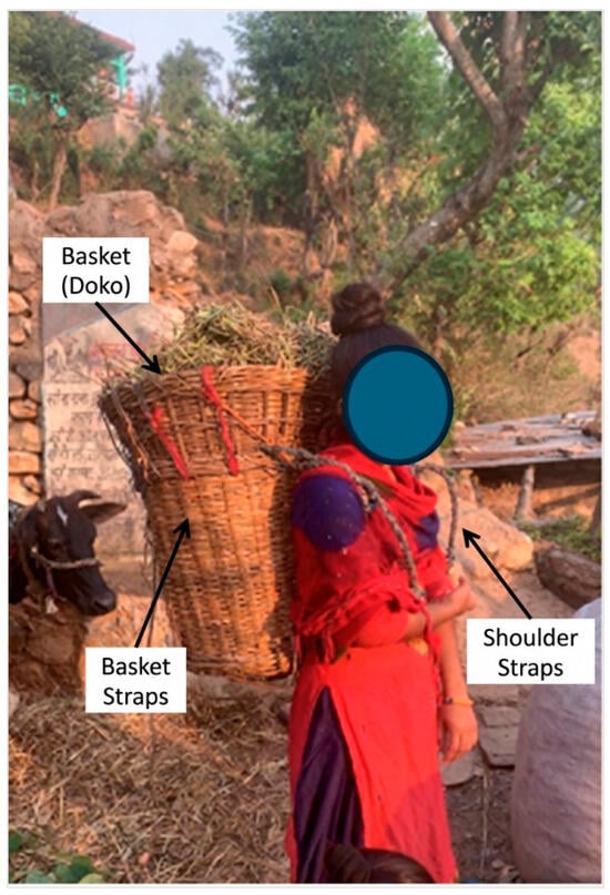
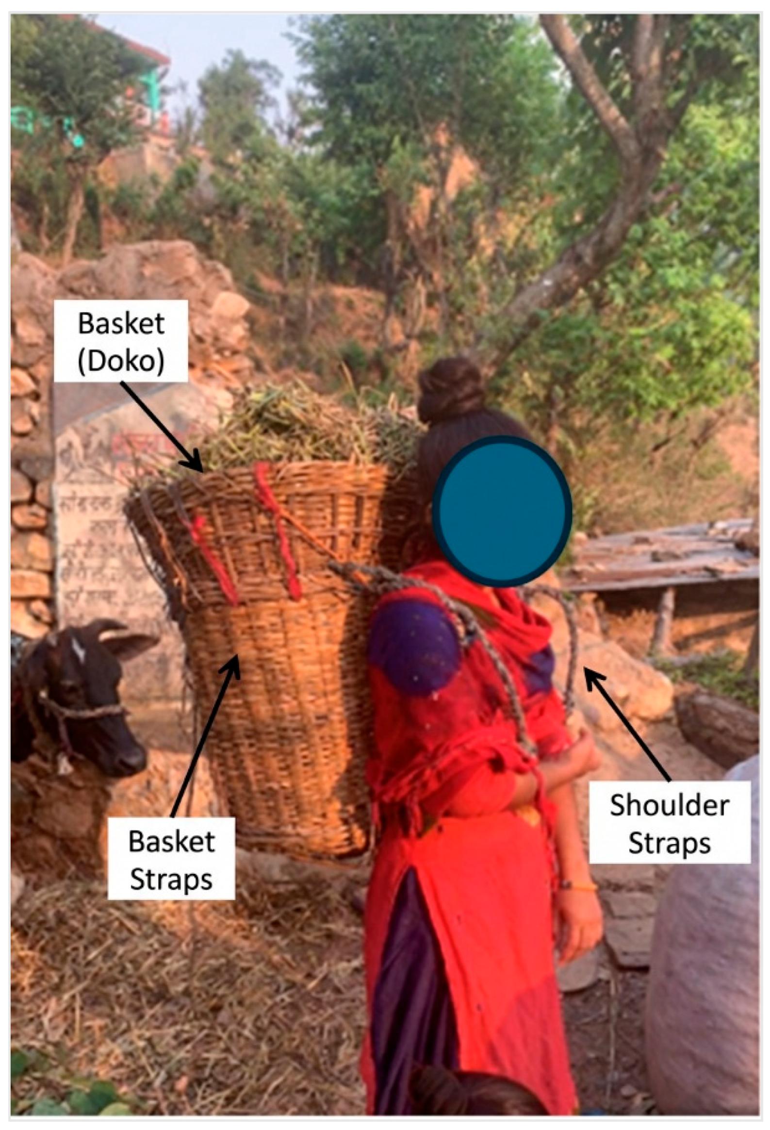
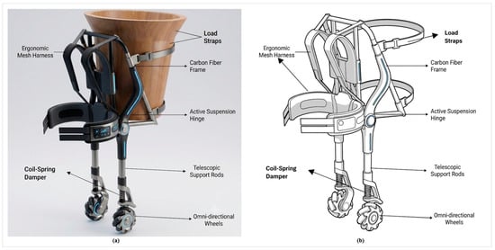
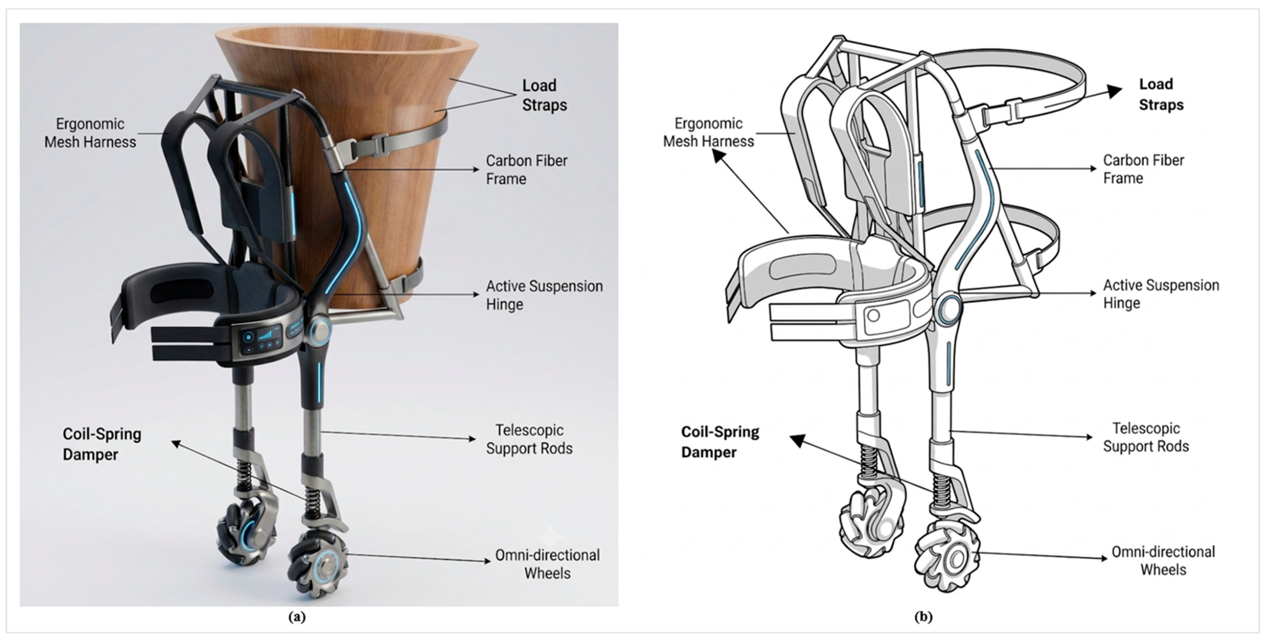
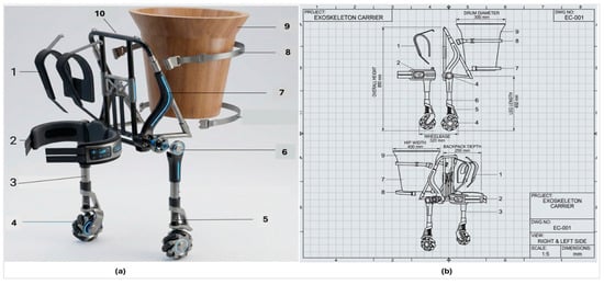
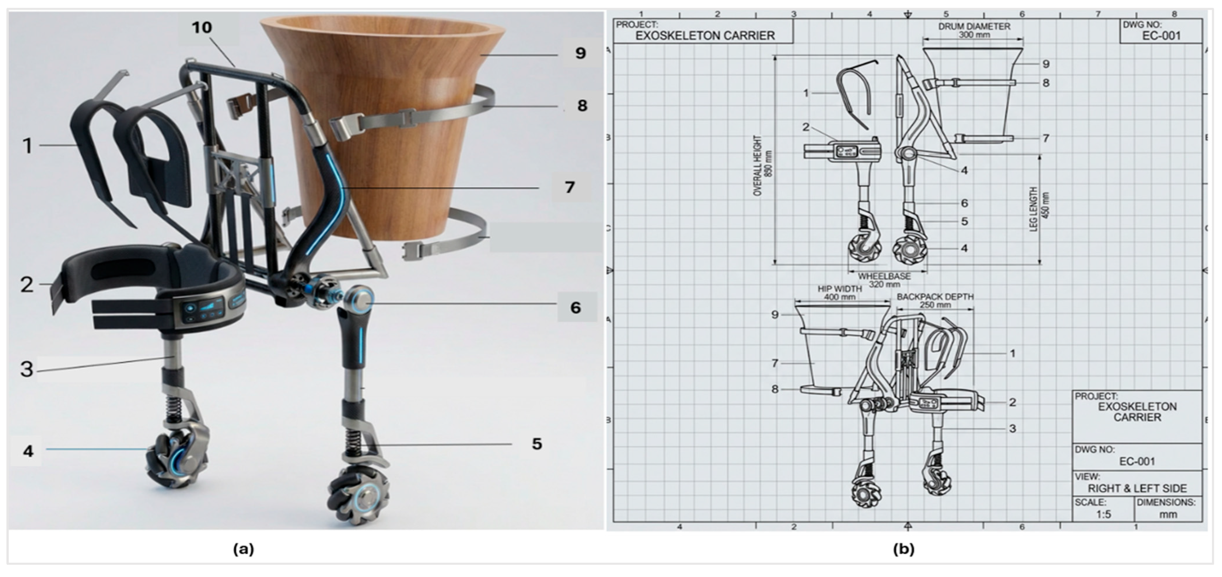
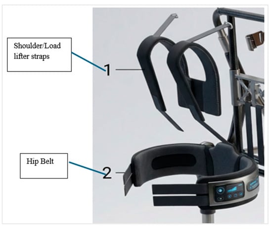
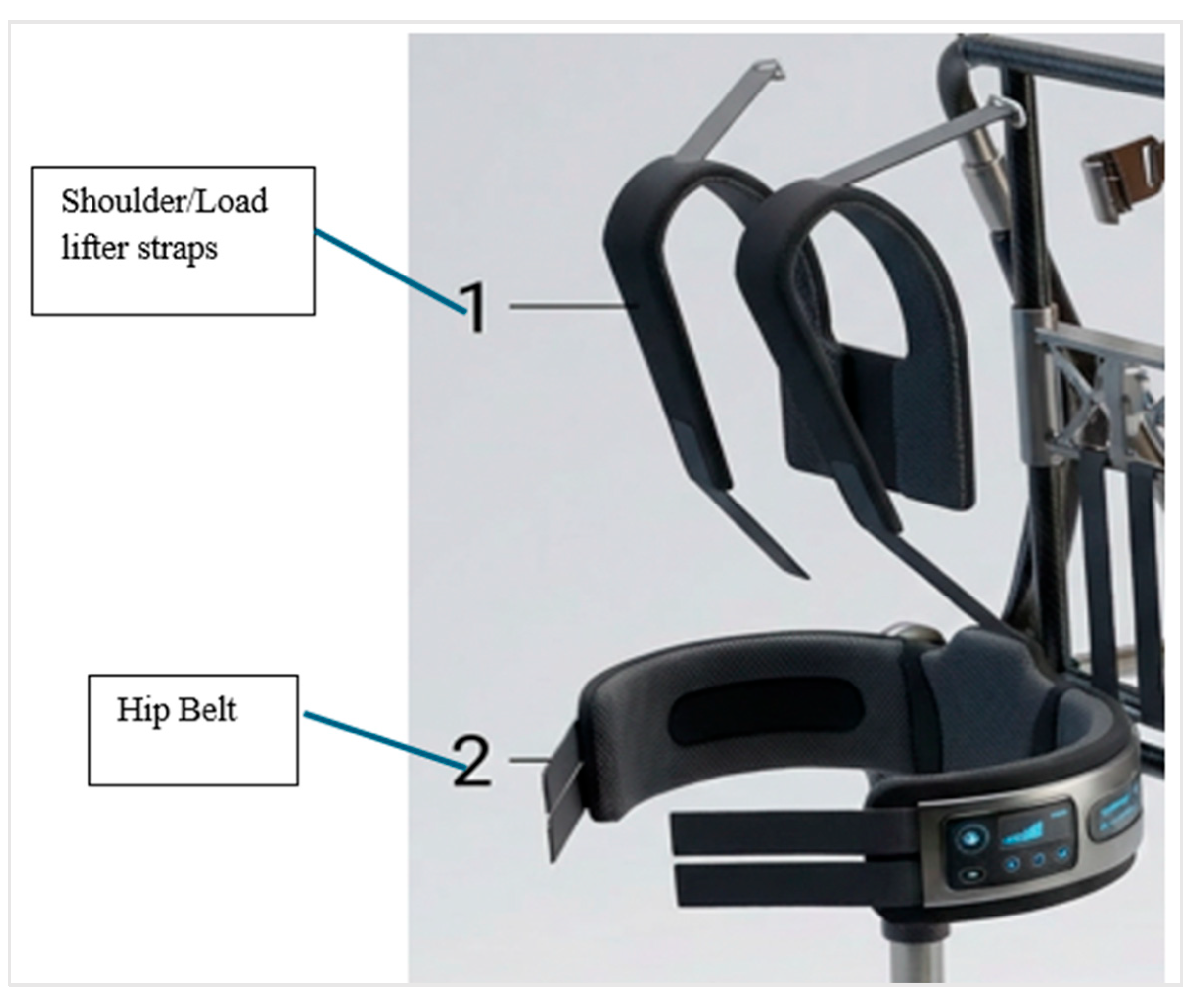
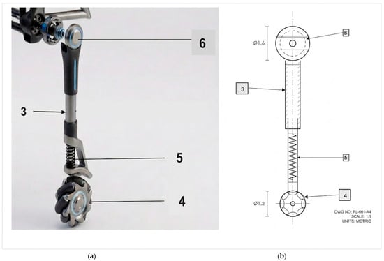
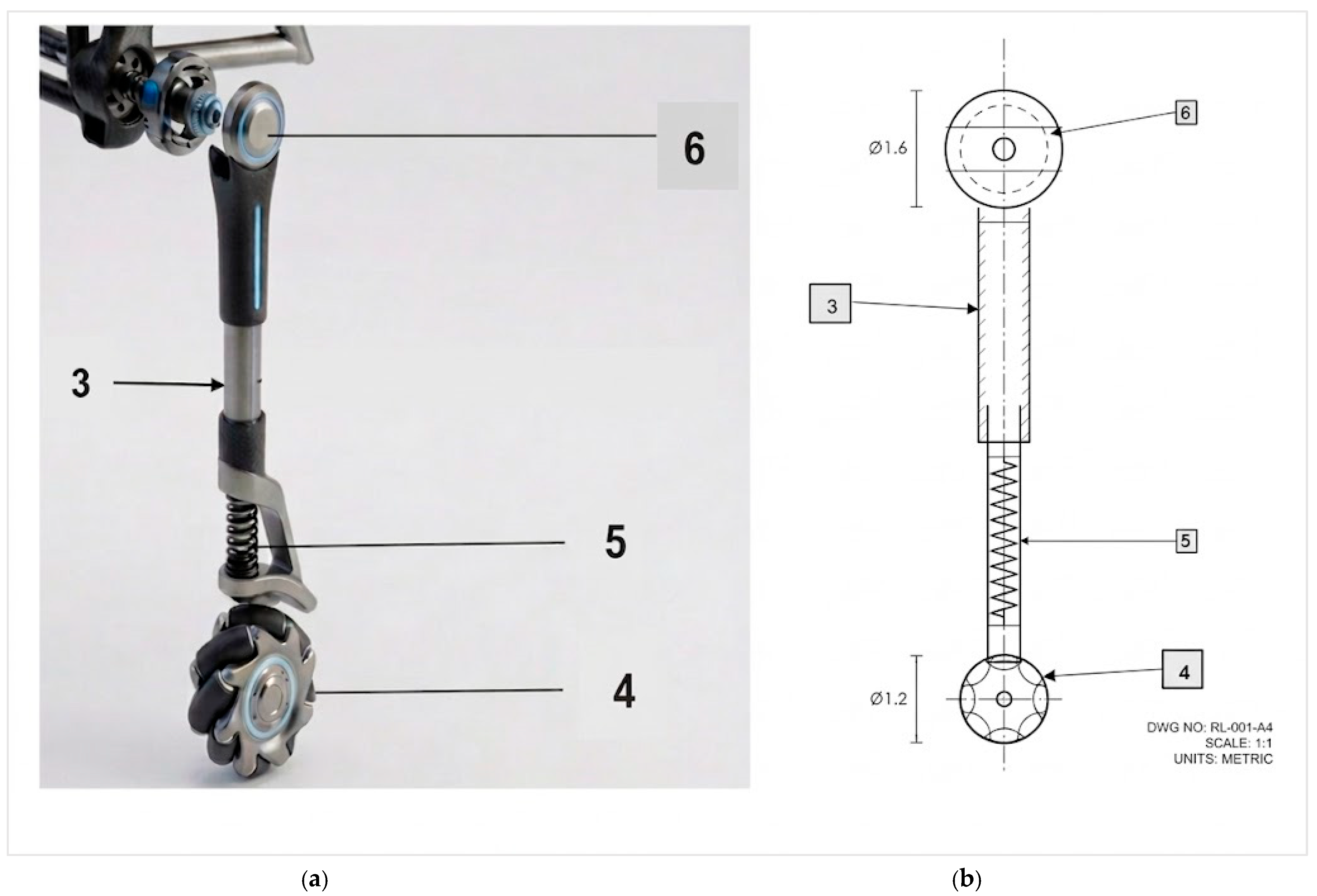
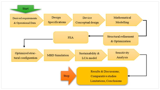
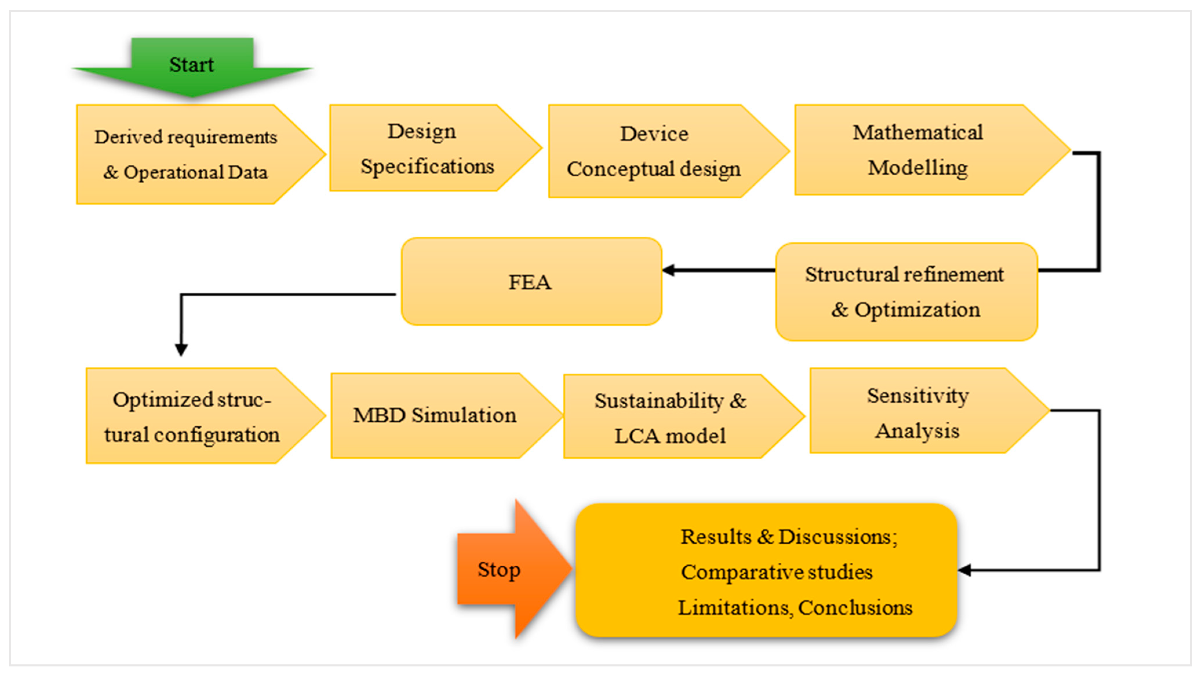
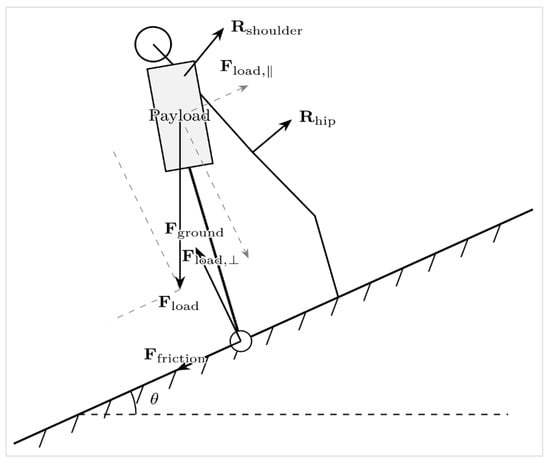
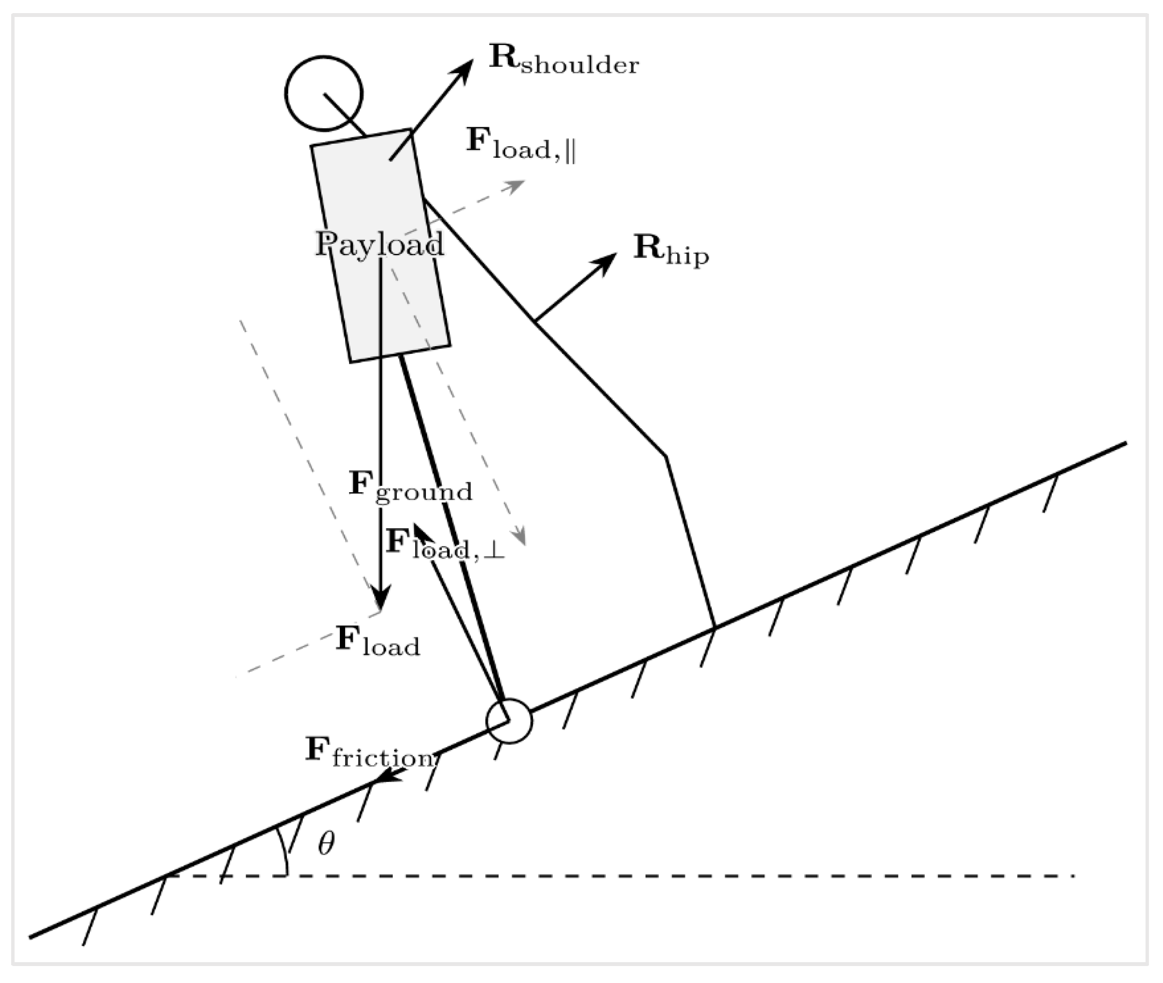
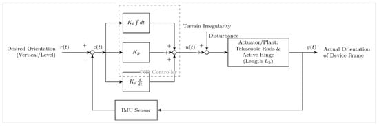
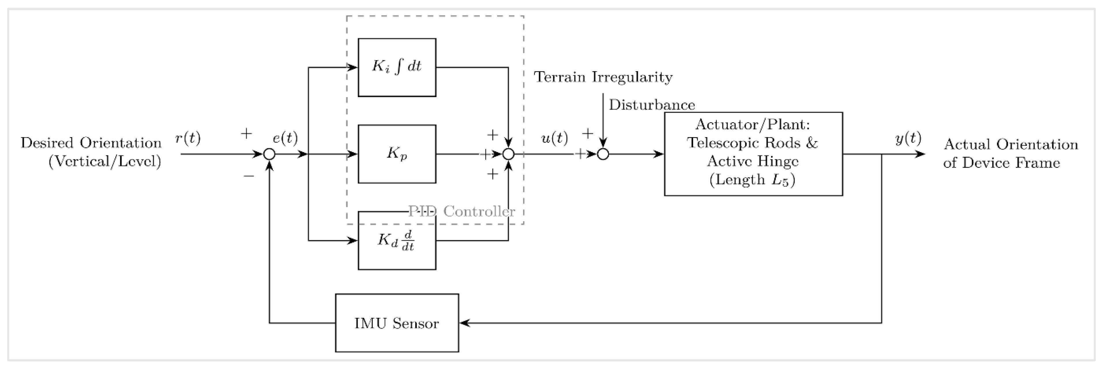
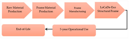
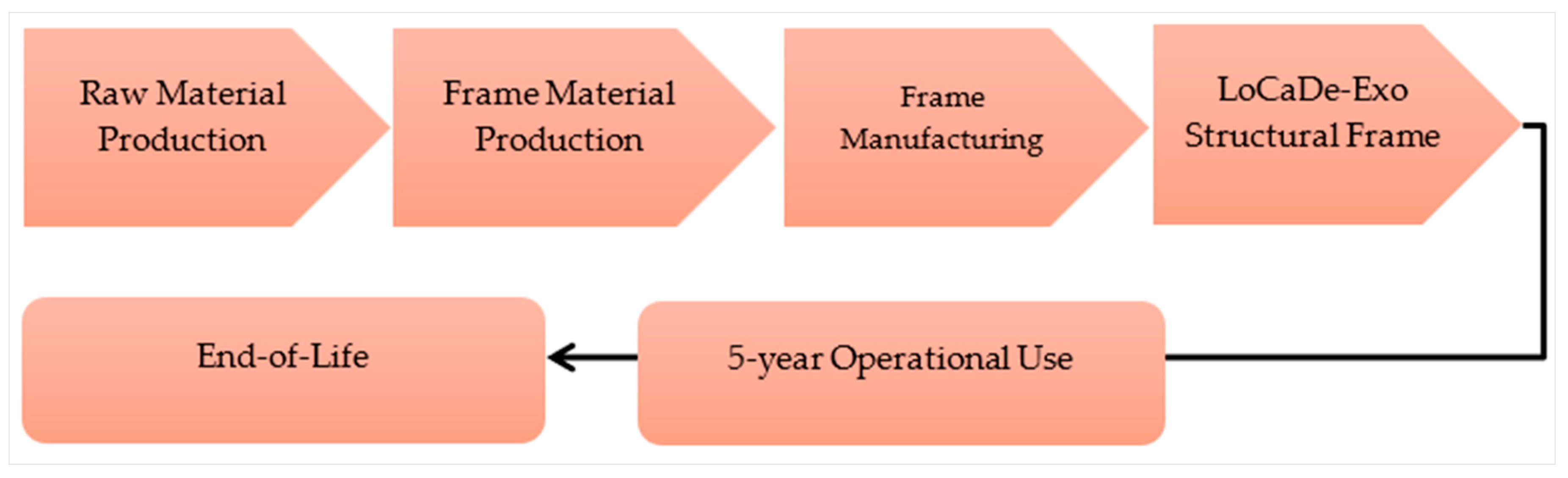
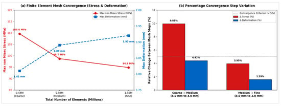
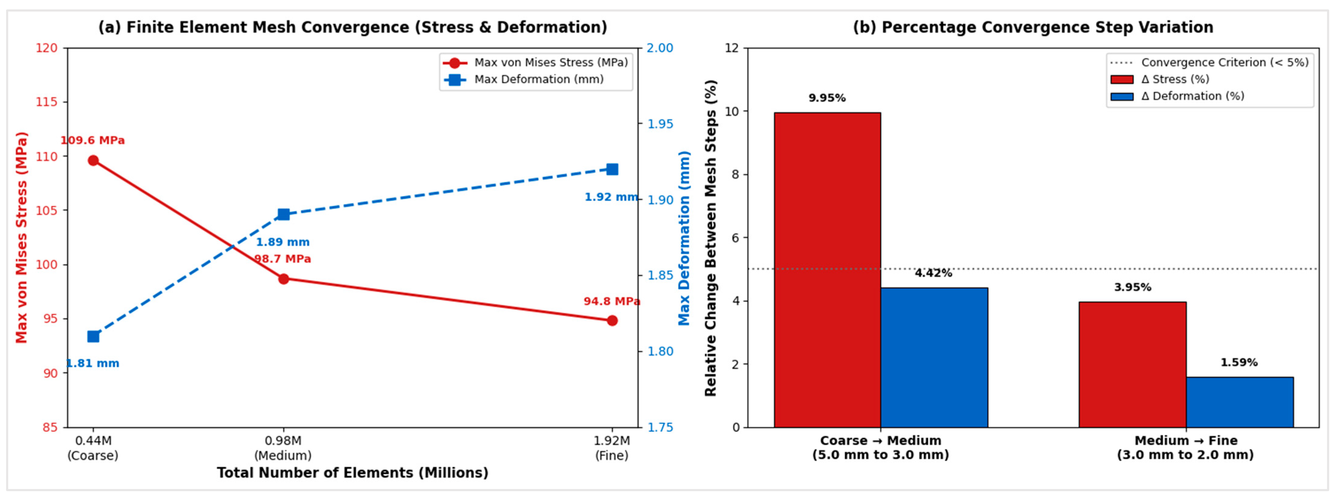
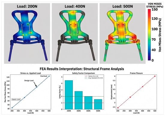
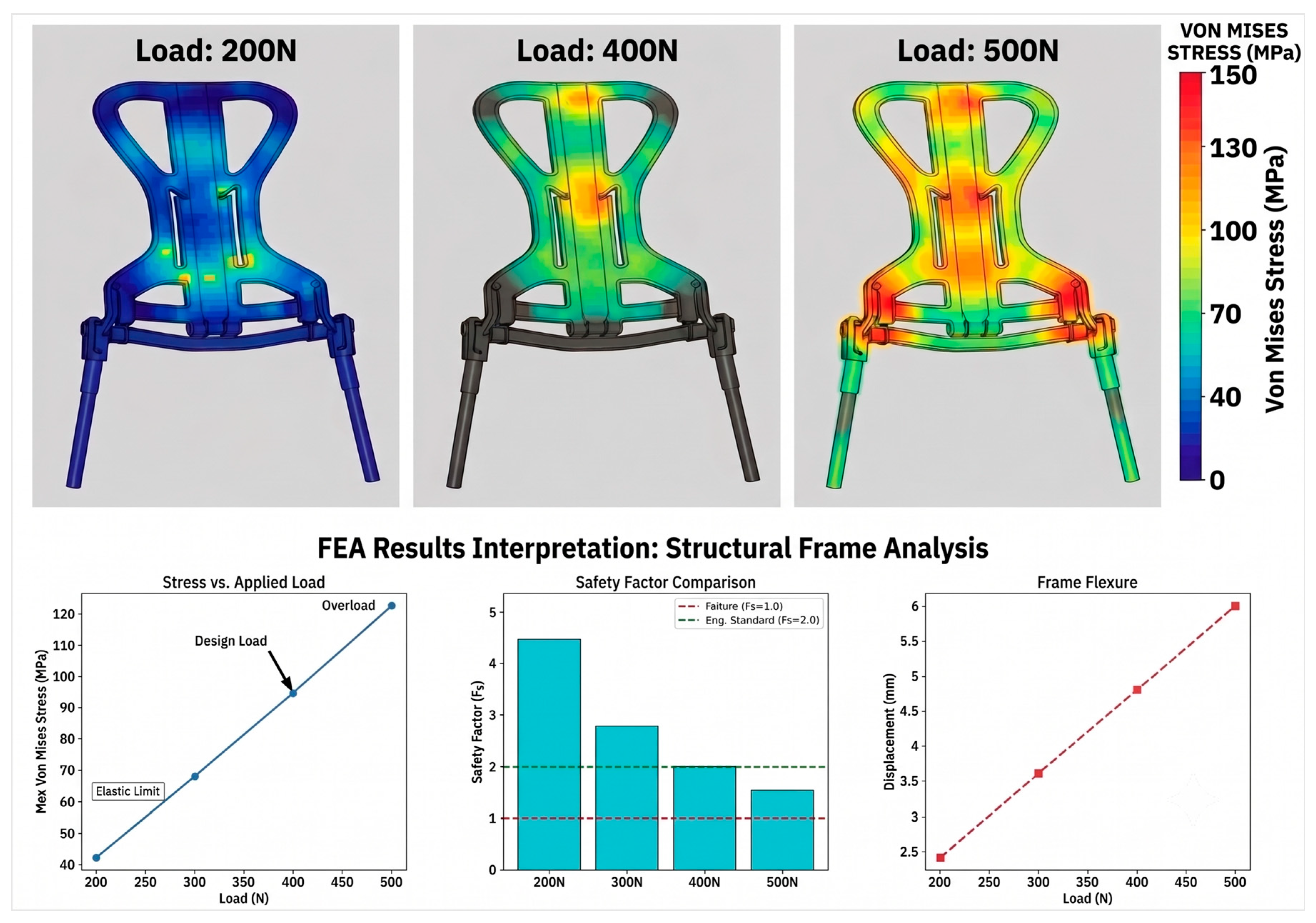
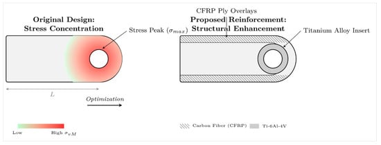
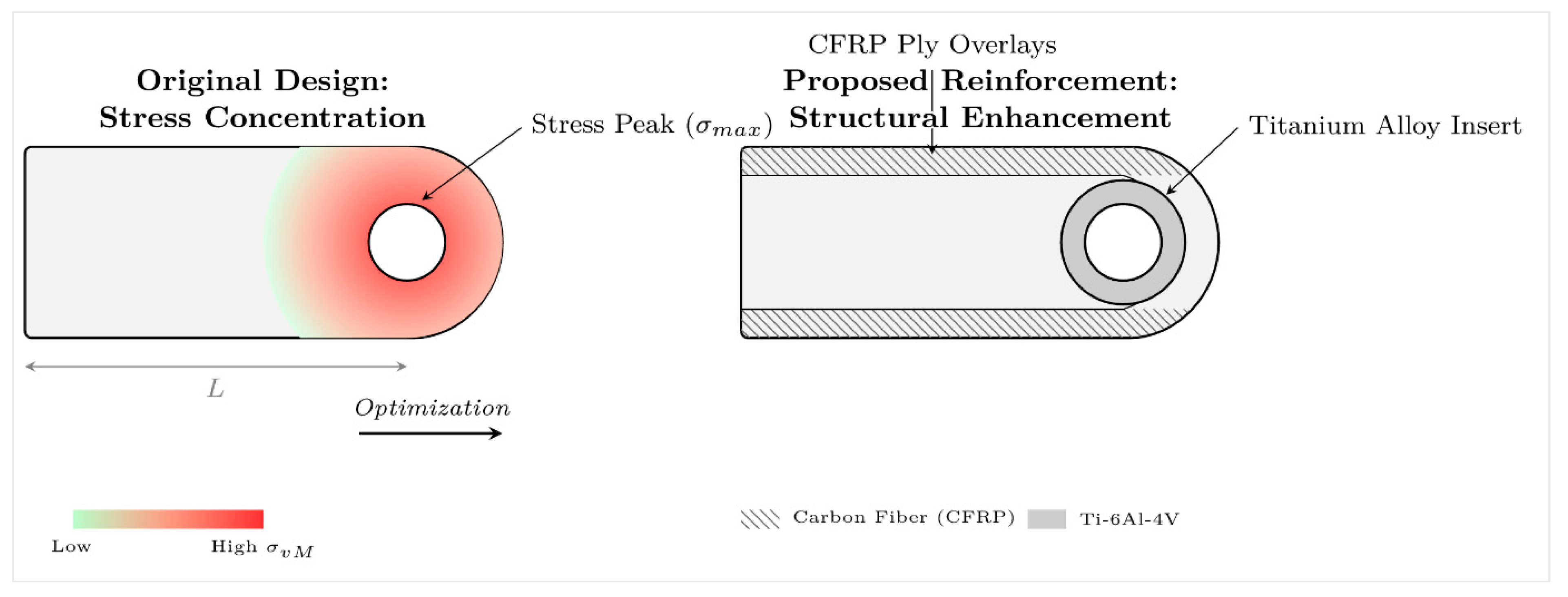
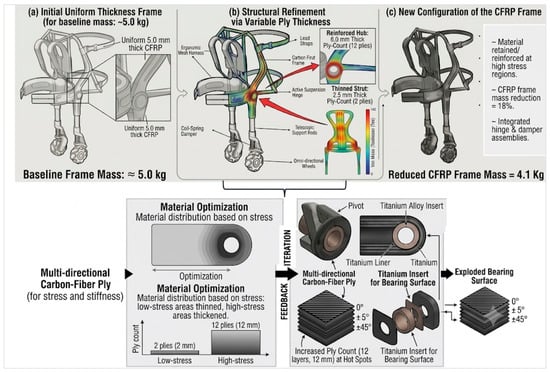
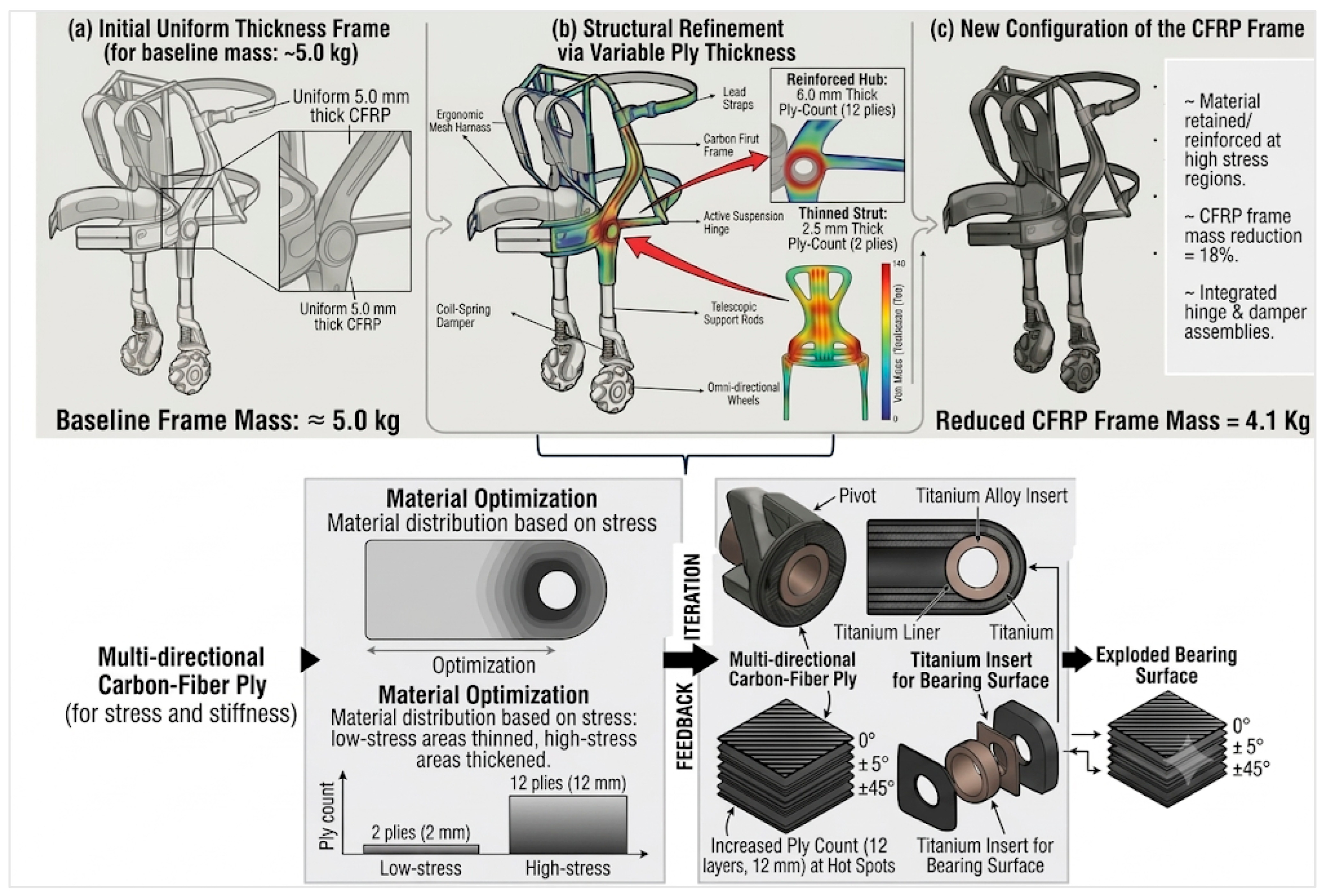
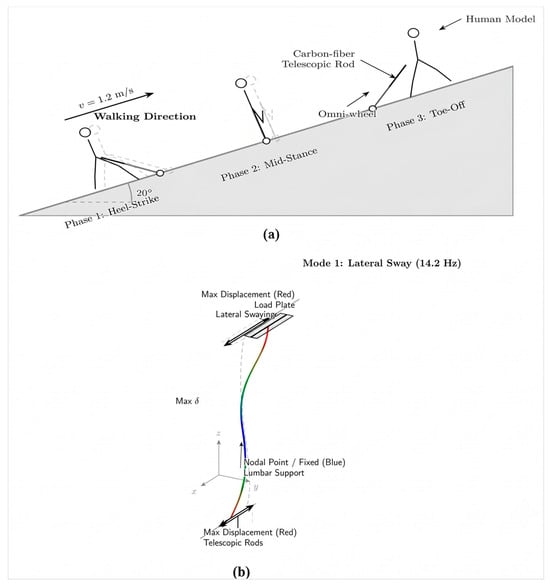
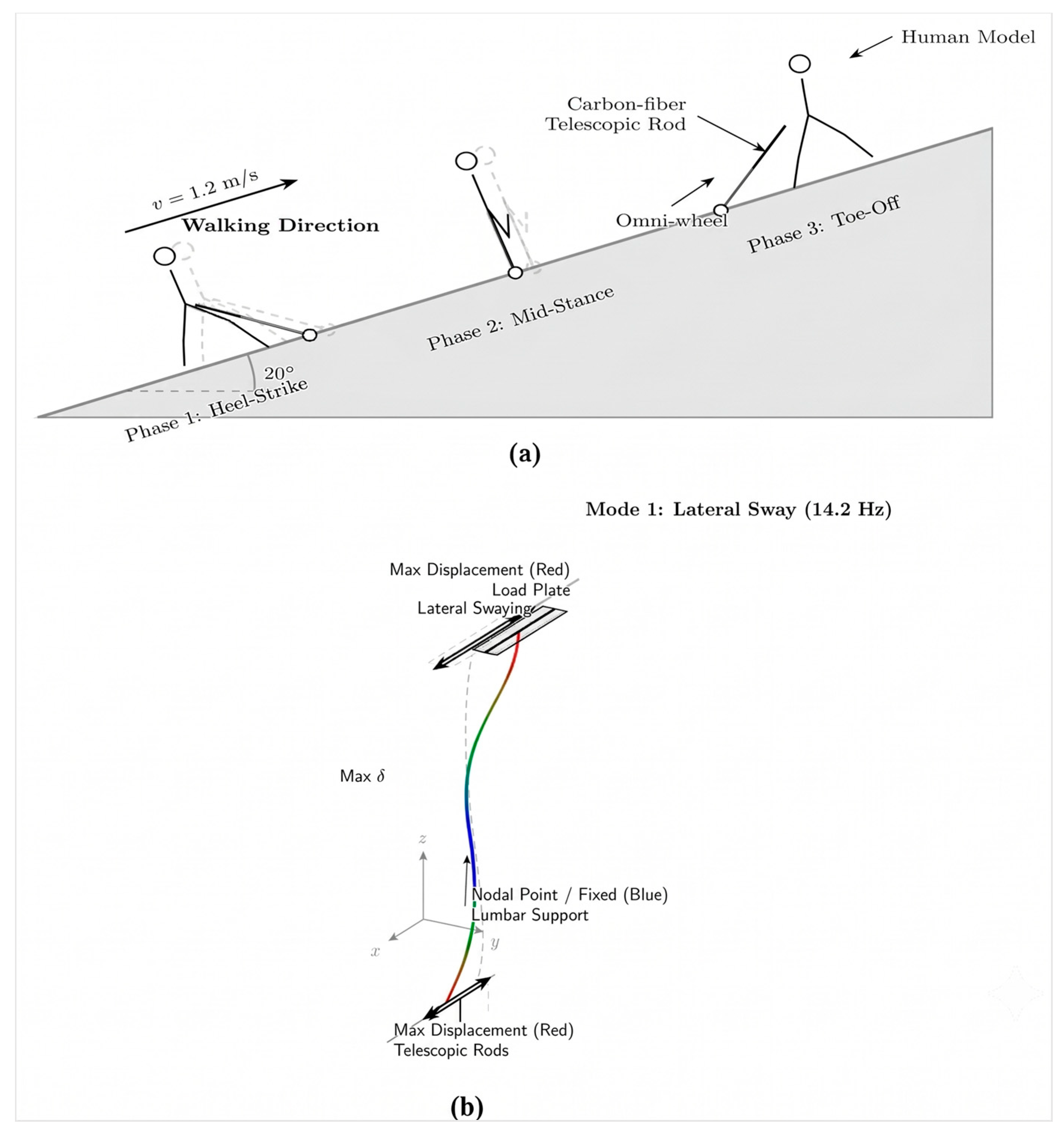
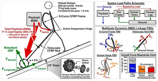
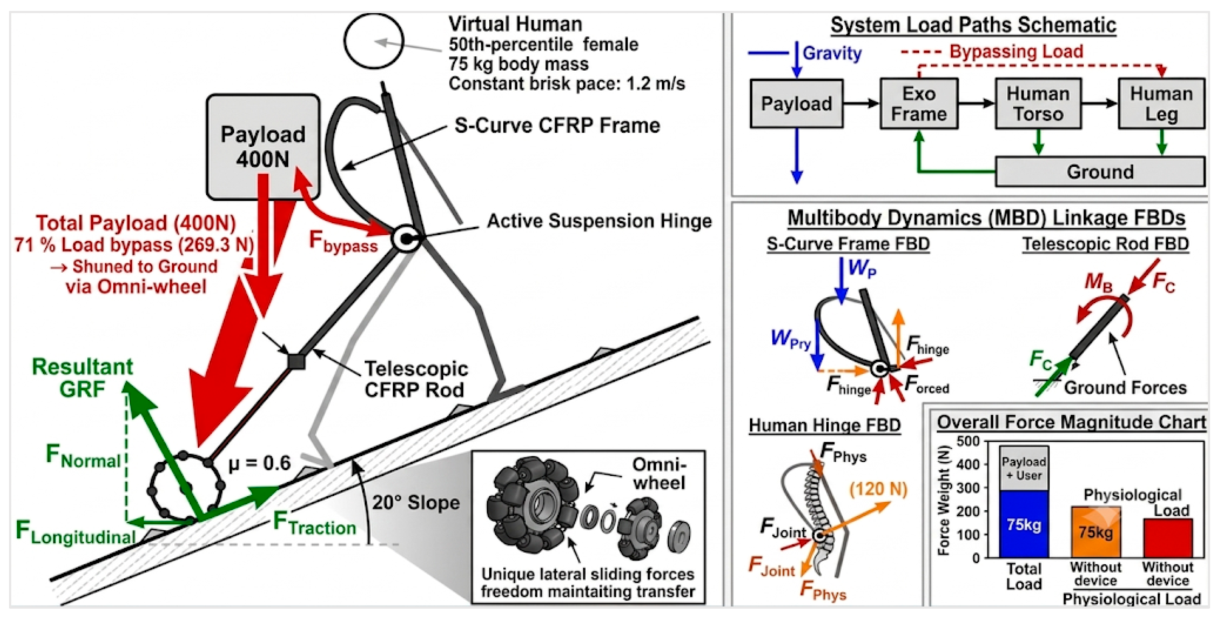
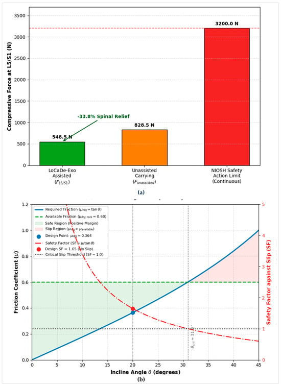
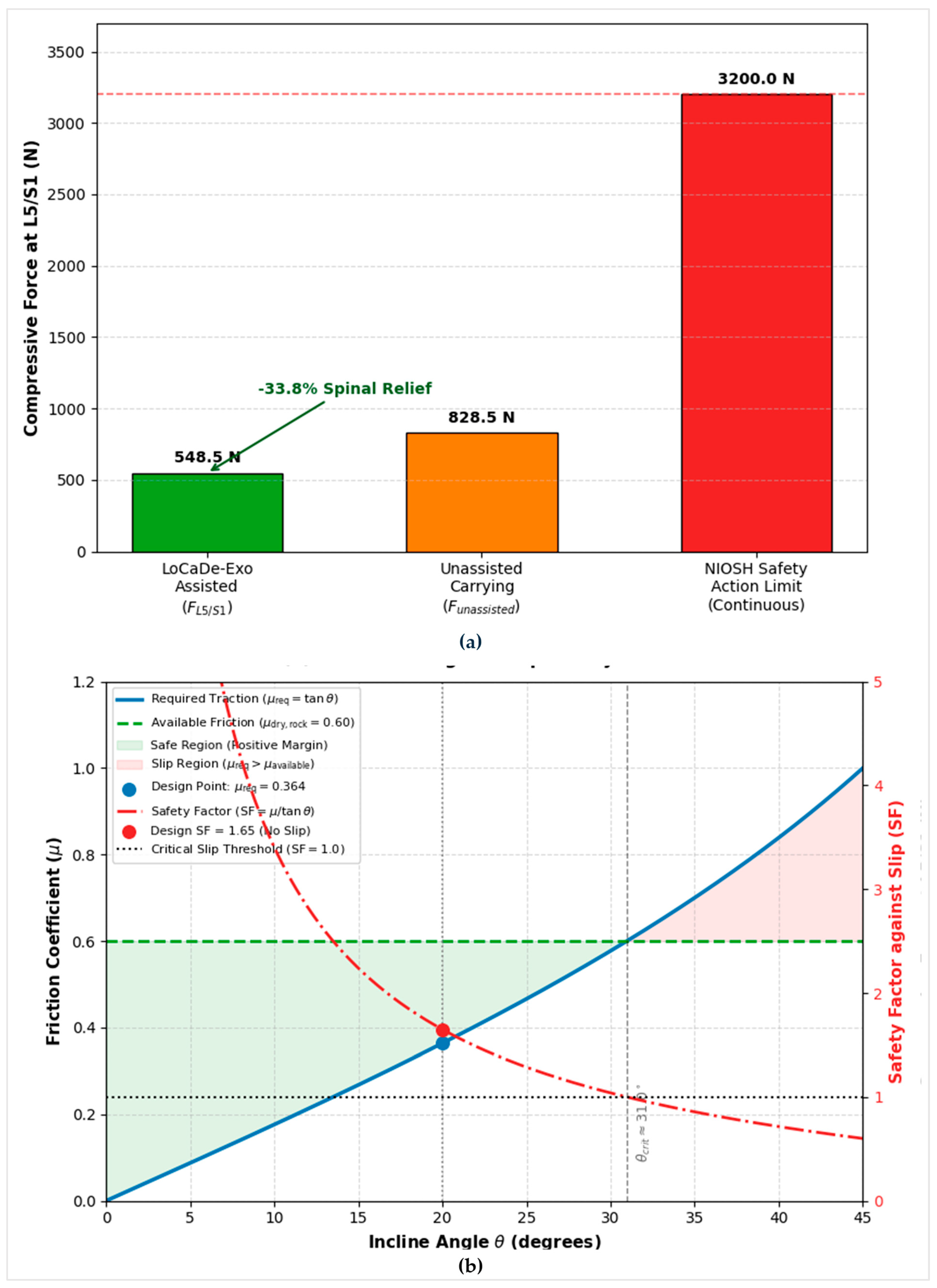
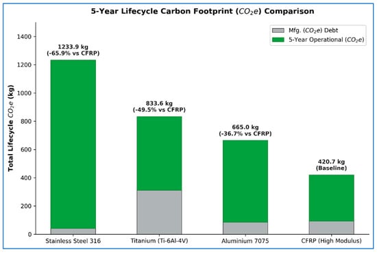
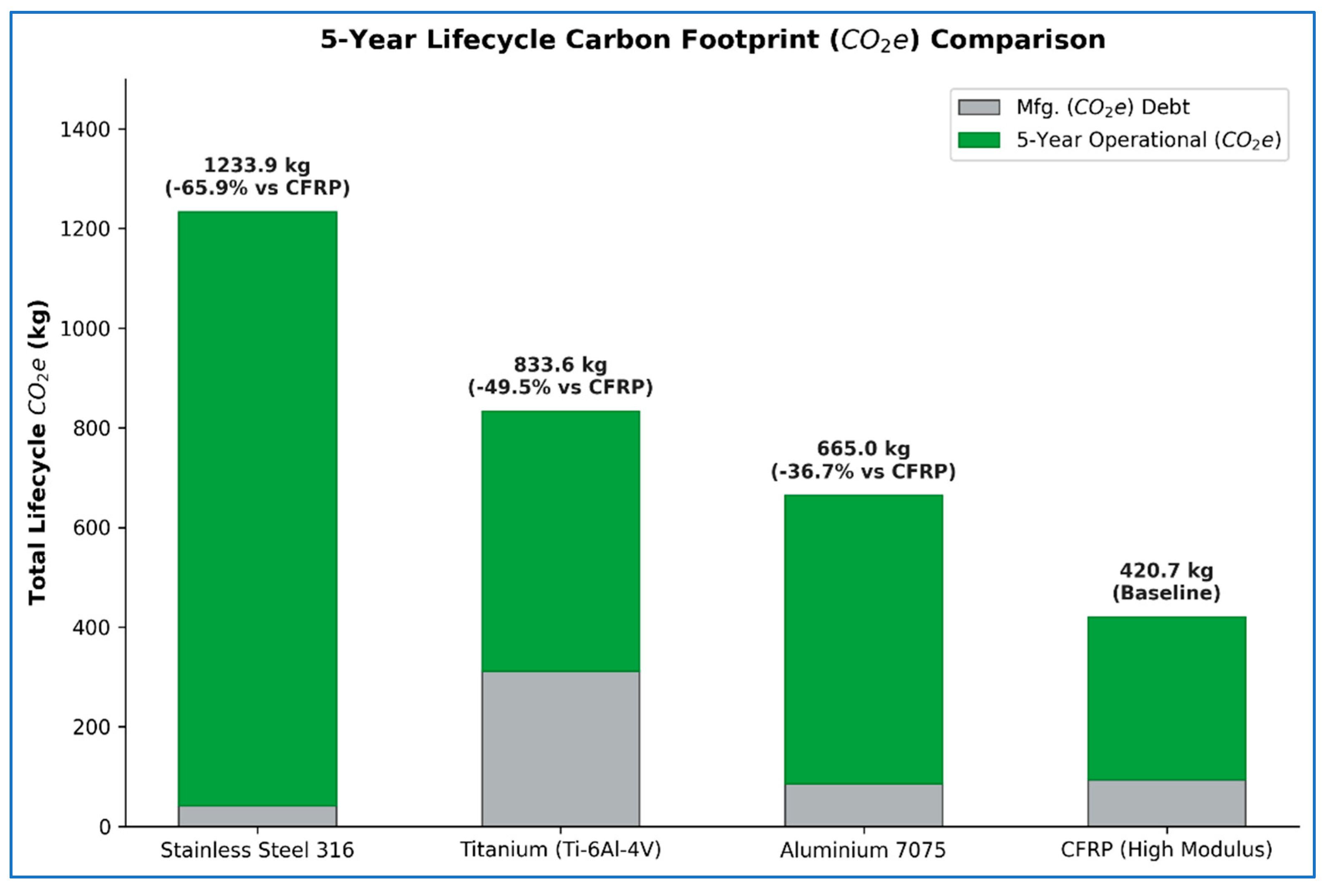

Disclaimer/Publisher’s Note: The statements, opinions and data contained in all publications are solely those of the individual author(s) and contributor(s) and not of MDPI and/or the editor(s). MDPI and/or the editor(s) disclaim responsibility for any injury to people or property resulting from any ideas, methods, instructions or products referred to in the content. |
© 2026 by the authors. Licensee MDPI, Basel, Switzerland. This article is an open access article distributed under the terms and conditions of the Creative Commons Attribution (CC BY) license.