


Abstract
Using the No. 1513 return air roadway at Anyang Coal Mine as an engineering case, this study examines the instability mechanism and support control of three-soft coal-seam roadways. An integrated approach combining theoretical derivation, physical similarity modeling, and FLAC3D simulation was adopted to analyze fracture propagation, deformation characteristics, and support optimization of roadway surrounding rock containing weak interlayers under mining-induced disturbance. The results indicate that the weak interlayer in the immediate roof disrupts load transfer among roof strata and promotes roof separation and fracture development. Calculations based on composite beam theory show that effective anchorage reduces roof separation displacement by approximately 74%. Therefore, bolts and cables should be arranged to constrain the weak layer within the effective anchorage range and improve roof stability. The physical model reveals that fractures evolve progressively under mining-induced stress, following a three-stage process: local initiation in the ribs, deep extension toward the roadway shoulders, and roof–shoulder–rib separation coalescence. FLAC3D results further show that secondary mining intensifies roadway deformation. The maximum roof subsidence, rib convergence, and roof plastic-zone height reach 532 mm, 1100.5 mm, and 5.5 m, respectively. The deep roof, roadway shoulders, and middle rib sections are therefore identified as the primary reinforcement zones. On this basis, a coordinated roof–shoulder–rib support system was proposed by increasing roof-cable density, adding rib cables, and increasing bolt density in the roof and ribs. After optimization, roof-to-floor convergence and rib deformation were effectively controlled. The results provide guidance for surrounding-rock stability control and support-parameter optimization in three-soft coal-seam roadways.
1. Introduction
With increasing mining depth and intensity, roadway surrounding rock is increasingly subjected to the combined effects of in situ stress, mining-induced abutment pressure, and support interaction. These coupled effects may induce roof subsidence, rib convergence, roadway-shoulder damage, and support failure, particularly under repeated mining disturbance [1,2,3]. In three-soft coal seams, which are characterized by weak roofs, coal seams, and floors, the surrounding rock generally exhibits low strength, weak cementation, and well-developed structural planes and fractures. Consequently, mining disturbance can readily induce continuous large deformation and progressive failure, posing substantial challenges to roadway stability and safe working-face extraction [1,4,5,6].
Recent studies have extensively investigated the deformation and failure characteristics of three-soft coal-seam and soft-rock roadways under mining disturbance. Li et al. [1] showed that the combined effects of weak surrounding rock and high stress can produce severe deformation and support difficulties in deep three-soft coal-seam roadways. Qian et al. [3] compared roadway responses under first and secondary mining disturbances and found that secondary mining further increases abutment pressure and surrounding-rock deformation, while Yang et al. [2] similarly reported a greater failure range and stronger stress concentration under secondary mining. From the perspective of roof failure, An et al. [4] demonstrated that mining-induced stress redistribution can promote progressive roof damage and that the damaged range may extend beyond the effective bolt anchorage zone. Zhou et al. [5] reported that low-strength and weakly cemented surrounding rock promotes progressive deformation and failure, and Li et al. [6] showed that strong mining disturbance can markedly intensify roof deformation, rib convergence, and fracture development in deep soft-rock roadways. Zhang et al. [7] further demonstrated the close relationship between sectional coal-pillar configuration, mining-induced stress redistribution, and roadway stability. For roadways subjected to repeated mining, Xiong et al. [8] revealed that successive disturbance promotes crack development, large-scale loosening, and progressive surrounding-rock instability, whereas Shang et al. [9] found that roadway deformation accumulates with repeated mining and that fracture evolution may exhibit pronounced spatial asymmetry. For roadways containing weak roof interlayers, Chang et al. [10] showed that weak interlayers can impair coordinated load transfer between roof strata and promote roof separation and progressive failure. These studies collectively indicate that roadway instability develops progressively through the combined effects of mining-induced stress redistribution, fracture propagation, weak structural planes, and cumulative disturbance.
Recent research on roadway control has increasingly shifted from simply increasing support strength toward coordinated reinforcement matched to the deformation and failure characteristics of the surrounding rock. Fu et al. [11] proposed hierarchical reinforcement using long and short cables to coordinate the control of deep and shallow surrounding rock, while Xu et al. [12] developed a pressure-relief, stress-transfer, and reinforcement strategy for three-soft coal-seam roadways subjected to strong mining pressure. From the perspective of support-deformation compatibility, Kaiser and Moss [13] emphasized that support design should consider deformation demand in addition to load-bearing capacity. Cheng et al. [14] demonstrated that the deformation and failure characteristics of deeply buried gob-side roadways are strongly affected by mining-induced stress redistribution and that targeted reinforcement should be arranged according to the dominant damaged zones. More recently, Wu et al. [15] investigated integrated anchoring–shotcreting–grouting control for large deformation in soft-rock roadways, while Li et al. [16] proposed a collaborative reinforcement system based on the identified failure characteristics of a deep soft-rock roadway. Wang et al. [17] further emphasized that the formation, expansion, and spatial morphology of the surrounding-rock plastic zone are closely related to roadway failure mode and support effectiveness. Xie et al. [18] proposed a combined external reinforcement and internal pressure-relief strategy for a severely mining-disturbed roadway, further demonstrating the importance of matching support measures to the principal stress sources and key instability zones. These findings indicate that roadway stability depends not only on support strength but also on the compatibility between the effective reinforcement range, support configuration, and spatial distribution of the dominant failure zones.
Existing studies have provided a substantial basis for understanding the deformation and control of soft-rock and three-soft coal-seam roadways. However, the mechanical response of such roadways is strongly influenced by specific roof–coal–floor combinations and mining-stress conditions. For roadways containing weak roof interlayers and low-strength coal ribs, repeated mining disturbance may simultaneously promote roof separation, rib-fracture propagation, and roadway-shoulder damage. Therefore, further investigation of the progressive roof–shoulder–rib failure process and its relationship with the spatial distribution of key reinforcement zones is necessary for support optimization under such engineering conditions.
The No. 1513 return air roadway at Anyang Coal Mine is characterized by a weak interlayer in the immediate roof, low-strength coal ribs, and a weak floor. During mining, the roadway is jointly affected by lateral abutment pressure from the No. 1512 gob and advance abutment pressure from the No. 1513 working face, resulting in pronounced deformation of the roof and ribs. In this study, theoretical analysis, physical similarity modeling, FLAC3D simulation, and field monitoring are integrated to investigate the progressive failure and surrounding-rock control of the roadway. Building on existing studies, particular attention is given to the relationship between roof–shoulder–rib failure evolution and the identification of key reinforcement zones, based on which a coordinated roof–shoulder–rib support scheme is developed and evaluated through field monitoring. The results may provide a reference for surrounding-rock control under comparable geological and mining conditions.
2. Study Area and Research Methodology
Anyang Coal Mine is situated in the southeastern sector of the Weibei Loess Plateau, where the mining district is characterized by relatively low relief. A vertical-shaft, single-level system is used for mine development. The No. 5 seam constitutes the principal extraction horizon. Its mean cover depth is 370 m; seam thickness ranges from 1.35 to 7.10 m, with an average of 4.63 m, and the dip varies between 3° and 8°. Accordingly, it is a medium-thick, gently dipping coal seam. In the first mining district, the No. 1513 working face is bounded by the No. 1512 gob on the west and the planned No. 1515 working face on the east. Mining at this face employs fully mechanized longwall top-coal caving, with full caving adopted for roof management.
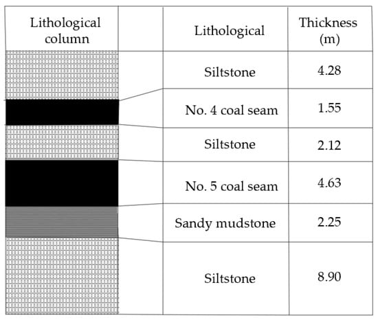
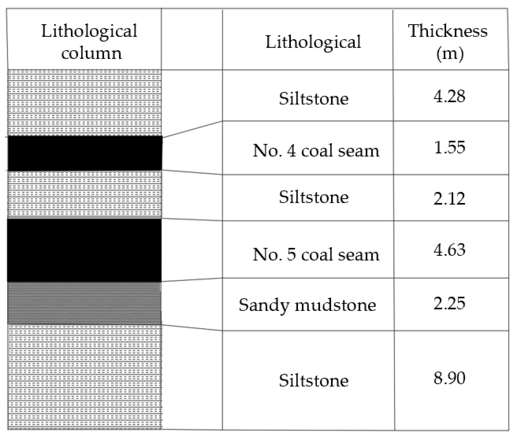
The strata associated with the No. 1513 return air roadway show typical three-soft features. Specifically, the No. 5 coal seam is soft, the immediate roof contains a weak interlayer associated with the No. 4 coal seam, and the immediate floor comprises water-swelling sandy mudstone. This roof–coal–floor assemblage has limited overall bearing capacity, and its lithological profile is presented in Figure 1. Under mining disturbance, the weak interlayer impairs load transfer between the immediate roof and main roof, thereby promoting roof separation and fracture propagation. Meanwhile, the low strength of the rib coal makes it susceptible to extrusion deformation and rib failure under high-stress conditions.
Figure 1.
Columnar diagram of the main lithologies of the roof and floor strata.
The roadway adopts a straight-wall arched section with dimensions of 4.8 m × 3.7 m and a net area of 16.03 m2. The initial support system consisted of bolts, mesh, and shotcrete. Roof reinforcement comprised Φ20 mm × 2500 mm bolts arranged at 700 mm × 800 mm and Φ21.6 mm × 6200 mm cables arranged at 1400 mm × 1600 mm. The ribs were reinforced with Φ20 mm × 2500 mm bolts at 700 mm × 800 mm spacing. A double-layer mesh was also used, consisting of an inner Φ6.5 mm steel-wire mesh and an outer No. 10 wire mesh. During mining, the roadway surrounding rock underwent severe deformation under mining-induced stress, as reflected by roof subsidence, pronounced rib convergence, local mesh bagging, roof separation, and bolt and cable failure. These failures required extensive repair work and posed a serious threat to safe production. These field observations indicate that the failure mechanism of roadway surrounding rock in three-soft coal seams requires further clarification and that the support system requires targeted optimization.
To investigate the progressive instability and support control of the roadway surrounding rock, theoretical analysis, physical similarity modeling, numerical simulation, and field verification were integrated into this study. Fracture mechanics and weak-interlayer roof models were first employed to characterize rib-fracture propagation and roof-separation behavior. Physical similarity modeling was subsequently conducted under staged loading, with a hydraulic loading system used to apply the load and an optical total station and pressure sensors used to monitor deformation and stress responses, respectively. FLAC3D was then employed to analyze stress redistribution, deformation, and plastic-zone development during successive mining. Based on the identified failure mechanism and key reinforcement zones, a coordinated support scheme was developed and further evaluated through field monitoring in the No. 1518 return air roadway. Detailed model configurations, parameters, and loading procedures are provided in the corresponding sections.
3. Theoretical Analysis of the Failure Mechanism of Roadway Surrounding Rock
3.1. Mechanism of Fracture Propagation in Roadway Ribs
Three-soft coal seams, characterized by weak roofs, coal seams, and floors, generally exhibit poor lithification and well-developed internal joints and fractures. Under the disturbance of superimposed abutment stress during mining, these coal seams are highly susceptible to nonlinear progressive failure. To determine the critical conditions for fracture propagation in the roadway ribs, single-fracture and composite-fracture propagation models were established based on fracture mechanics theories, including the near-free-surface crack-growth framework proposed by Dyskin and Germanovich, the Irwin mode-I fracture criterion, and the compression-induced crack-extension mechanism described by Nemat-Nasser and Horii [19,20,21]. These theoretical foundations were adapted to the stress state and crack geometry of the present roadway.
For analytical tractability, several idealizations are adopted in the fracture mechanics model. Before unstable crack propagation, the coal surrounding a pre-existing crack is treated as a linear-elastic continuum, and the unloading effect of the roadway free surface is represented by a vanishing lateral stress at the free boundary. Mining-induced loading is represented by an equivalent quasi-static stress state, and crack initiation is determined using the Irwin criterion when the mode-I stress intensity factor reaches the fracture toughness. For the multi-fracture case, interacting cracks are idealized as periodically distributed collinear cracks of equal length and spacing. The model is used to estimate the critical conditions for crack initiation and coalescence in the roadway ribs.
- (2)
- Mechanical Model for Unstable Propagation of a Single Microcrack
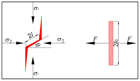
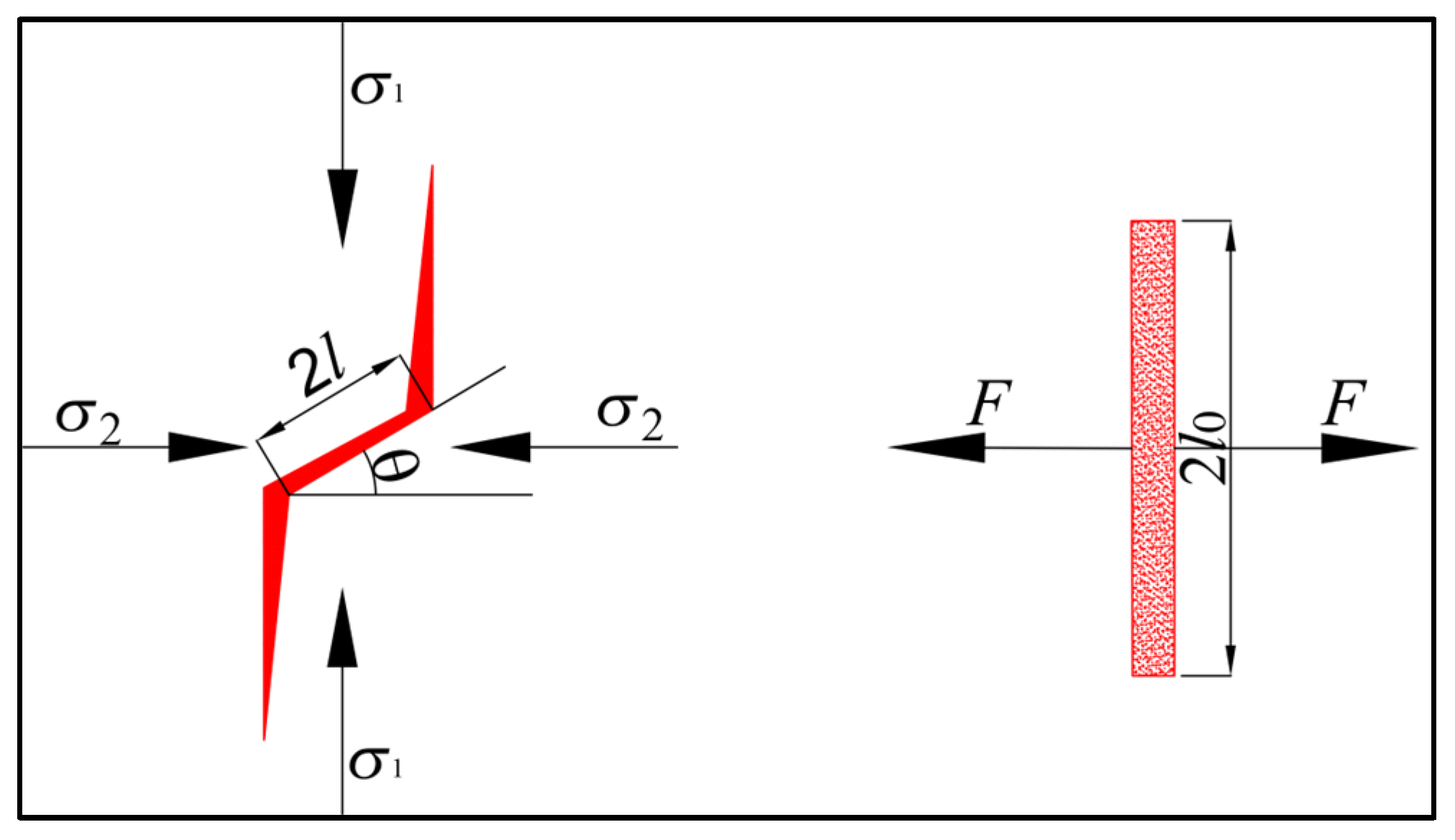
During the initial compression stage, considering the unloading effect of the roadway free surface, shear slip along a single microcrack within the coal body can be simplified as an opening-mode, or mode I, fracture subjected to a concentrated force F, as shown in Figure 2. The initial crack length, slip-surface length, and angle between the crack and the maximum compressive stress direction are denoted as 2l, 2l0, and θ, respectively. Accordingly, the equivalent force F is written as:
F = 2σzl0Cf(θ)
Figure 2.
Single-fracture propagation model.
Here, σz represents the vertical principal stress of the coal–rock mass, whereas C denotes a correction coefficient for fracture bending and friction.
To describe the high stress-gradient field around the crack tip under spatial confinement, the double-asymptotic method was used to calculate the mode-I stress intensity factor KI, with the free-boundary effect considered. The crack-free-surface spacing is denoted by h. The corresponding expression is written as:
Here, is used as the reference mode-I stress intensity factor for an isolated crack in an unbounded plate. Following the Irwin fracture criterion, crack growth occurs when KIC ≤ KI. Once this threshold is reached, unstable crack propagation is initiated, where KIC represents the material critical fracture toughness. By differentiating Equation (2) and applying the extremum condition, the critical length for unstable propagation of a single crack can be determined as lcr = 0.471h. Combining this result with the fracture criterion gives the critical stress for instability of a single microcrack as:
The overburden unit weight is denoted by γ. The self-weight stress can then be expressed as σz = γH. Therefore, the critical depth for unstable propagation of a single fracture in the single-fracture model can be expressed as follows:
- (2)
- Mechanical Model for Coalescence Failure of Compressive Fracture Groups
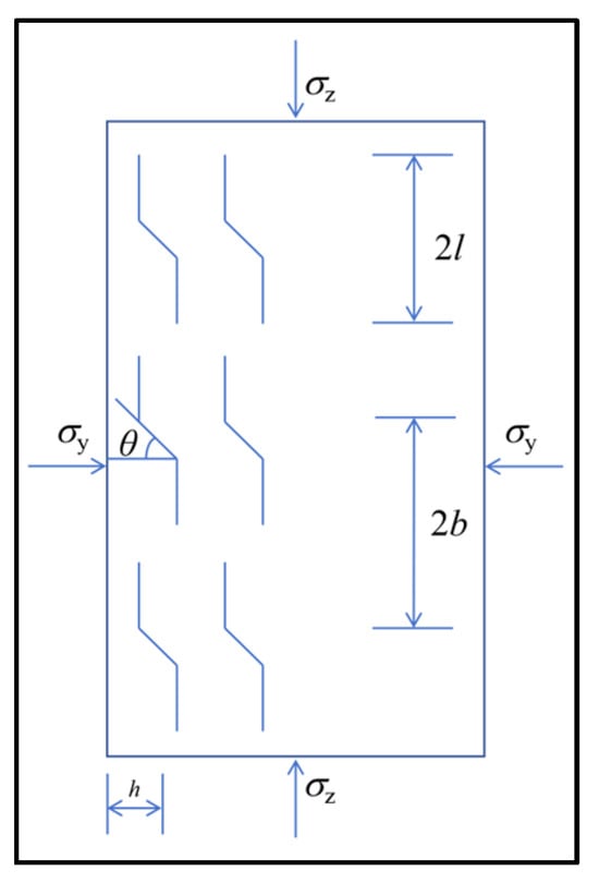
Owing to severe disturbance induced by secondary mining, the deep coal–rock mass within the supported zone enters a plastic flow state. Numerous fractures, driven by combined tensile–shear stresses, undergo local sliding along pre-existing weak joints and form periodic collinear composite fracture groups with a spacing of 2b, as shown in Figure 3.
Figure 3.
Plane sliding fracture model.
At this stage, the stress fields at the tips of adjacent fractures exhibit strong interaction effects. By introducing the function , which characterizes the effects of fracture size and position, together with the correction function , which accounts for multi-fracture interactions, the composite stress intensity factor can be derived as follows:
Here, , and the correction factor is set as . By incorporating the above boundary conditions, the critical depth for instability caused by composite-fracture coalescence under multi-fracture interaction can be derived as follows:
3.2. Deformation and Failure Mechanism of Roadway Roofs Containing Weak Interlayers
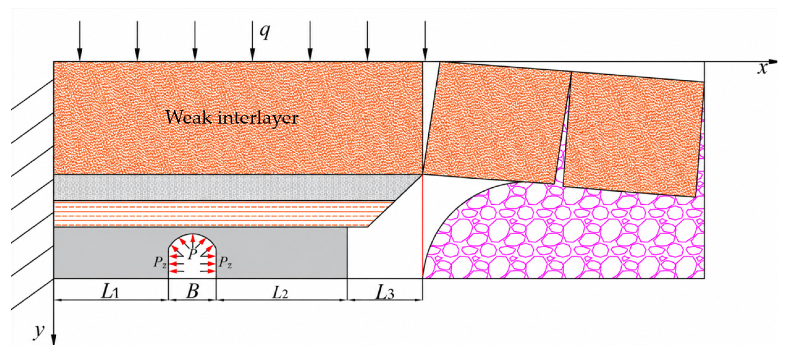
Because the roadway roof has a layered structure, differences in the mechanical properties of individual strata may lead to differential deformation near the weak interlayer. To quantify this deformation, the roof strata are represented by a beam model subjected to quasi-static vertical loading. The coal-pillar bearing load is assumed to remain stable during each calculation stage, and the peak-stress positions determined from limit-equilibrium analysis are treated as fixed boundaries. Before macroscopic roof instability, the strata are assumed to follow linear-elastic and small-deflection beam behavior, while the overburden load, support load, and coal-pillar load are combined by superposition. The analytical formulation follows the mechanical framework previously used to characterize deformation and separation of roadway roofs containing weak interlayers [10], and is adapted to the roof structure and loading conditions of the No. 1513 return air roadway. The resulting beam model is used to quantify the deformation and separation associated with the weak interlayer, as illustrated in Figure 4.
Figure 4.
Mechanical representation of the weak-interlayer roof.
Under the limit-equilibrium assumption, the peak-stress positions in the immediate and main roofs are taken as fixed ends. The distance from these fixed ends to the roadway rib is denoted by L1 and is obtained as:
Here, λ is the coefficient of lateral pressure; h denotes the extraction thickness; and φ′ represents the friction angle along the discontinuity in the rock strata. The quantities km, H, and C correspond to the stress-concentration factor, cover depth at the working face, and discontinuity cohesion, respectively. Pz denotes the confining reaction exerted by the support system on the solid-coal rib.
The loading acting on roof strata adjacent to the weak interlayer comprises the overburden load q, roof support load P, and support load σ supplied by the sectional coal pillar. A symmetric vertical-stress distribution is assumed for the sectional coal pillar. The support stresses on the gob-side and roadway-side of the sectional coal pillar are denoted by σ1 and σ2, respectively. The corresponding calculation formula is given as follows:
The cohesion and friction angle of the roof strata are denoted by C′ and φ, respectively. The coal-pillar height is represented by m, whereas k′ characterizes reinforcement on the roadway-facing side of the coal pillar.
Applying superposition under static equilibrium, the deflection function of the single-layer beam subjected to overburden load q is written as:
where x denotes the distance of an arbitrary roof section measured from the clamped end. The variables B and L2 represent the roadway opening width and coal-pillar span, respectively. E is the Young’s modulus of the roof rock mass, whereas Ip is the sectional second moment of area per unit width. The parameters ω and L3 denote the peak bending moment and cantilevered length, respectively.
Ip = h3/12
Within the composite-beam model, the overburden-induced load acting on the roof beam, q, is determined by:
where γi, hi, and Ei represent the unit weight, thickness, and Young’s modulus of stratum i, respectively.
Under the support load, the deflection of the single-layer beam is written as:
L1 ≤ x ≤ L1 + B
Here, let
For the coal-pillar bearing load σ, the corresponding single-layer beam deflection is derived as:
Here, let
u(x) = 3L2(L1 + B)x2 + L22x2 − L2x3
v(x) = 3L2(L1 + B)x2 + 2L22x2 − L2x3
In the theoretical model, the separation displacement of the weak interlayer is evaluated from the deflection difference between the strata immediately above and below it. When roof anchorage effectively encompasses the weak interlayer, the final deflections of the adjacent strata over the roadway span are obtained as:
From the above equation, the amount of separation of the weak interlayer within the anchor is:
Δ(x) = ωi − ωi+1
For the region beyond the anchorage zone, the weak-interlayer separation displacement is calculated as:
Δ′(x) = ωi − ωj
Equation (19) shows that, under field mining conditions, roadway roof displacement is governed primarily by the restraint provided by the roof support, the bearing action of the sectional coal pillar, and Young’s modulus of the roof strata. Increasing the restraint supplied by the roof support and sectional coal pillar can reduce roof deflection. During working-face extraction, however, the increasing overburden load may surpass the load-bearing capacity of the support system, thereby causing further roof displacement.
3.3. Engineering Case Study
Parameters used in the calculation were assigned according to the geological and mining setting of the No. 1513 return air roadway at Anyang Coal Mine. The lateral pressure coefficient, mining height, and friction angle of the rock-stratum structural plane were λ = 1.2, h = 5.15 m, and φ = 34°, respectively. A stress-concentration coefficient of 1.5 was adopted. The No. 5 coal seam occurs at an average burial depth of 370 m, and the sectional coal pillar is 20 m wide. The thicknesses of the immediate roof and main roof are 4.5 m and 10 m, respectively. The coal-body cohesion is C0 = 3.2 MPa, while the support resistance acting on the solid-coal rib is PZ = 0.2 MPa. After these parameters were substituted into Equation (7), the calculated plastic-zone width for the solid-coal rib was 2.1 m. The roof weak interlayer was identified as the No. 4 coal seam.
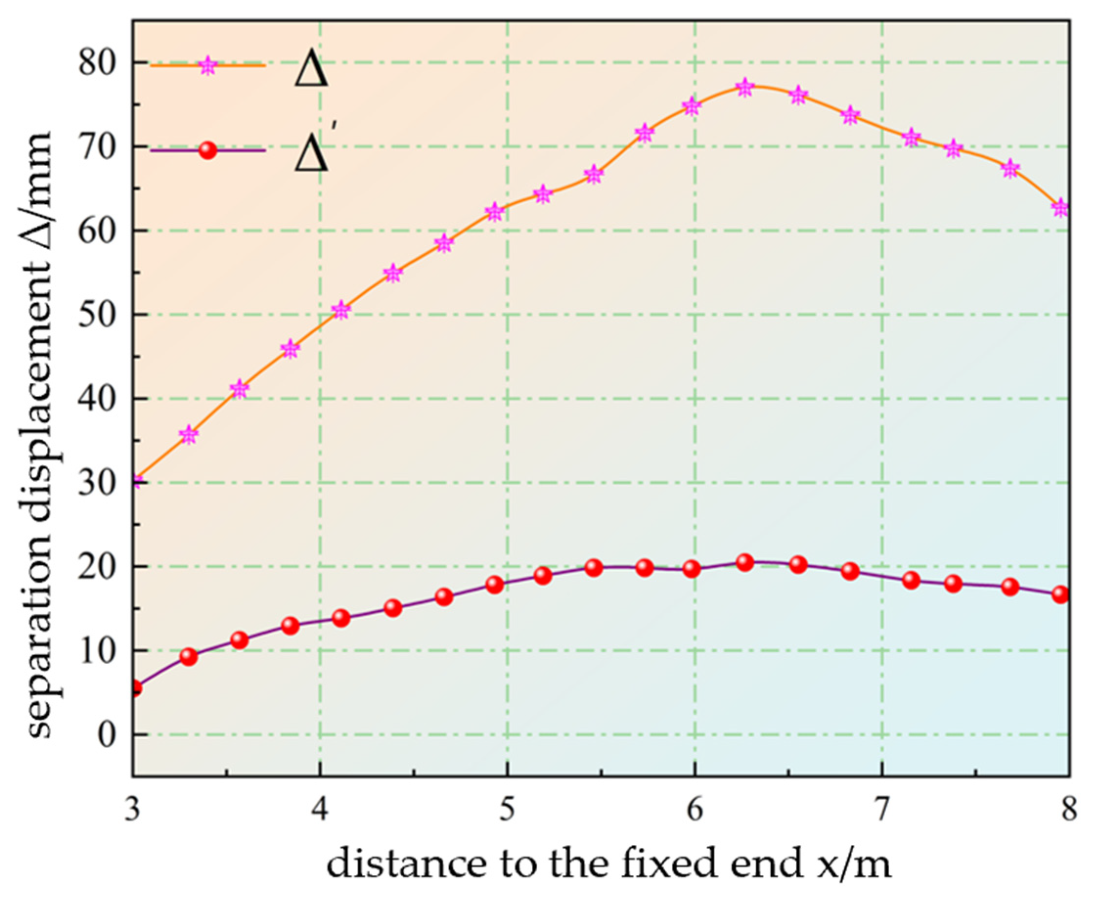
Roof displacement within a representative section of the roadway was analyzed. Equations (20) and (21) were used to determine weak-interlayer separation displacement on both sides of the anchorage boundary, with the calculated results presented in Figure 5. The maximum separation displacement was 78 mm outside the anchorage zone and 20 mm within it. The solid-coal rib underwent less movement than the pillar-side rib, suggesting that mining-induced stress produced an asymmetric deformation pattern.
Figure 5.
Variation curves of separation displacement inside and outside the anchorage zone.
When the anchorage system effectively covers the weak layer, roof displacement is reduced by approximately 74%. If the weak layer remains beyond the reinforced range, interlayer slip may intensify and may trigger surrounding-rock instability or local collapse. Therefore, the support design should ensure that the weak layer is constrained by the effective anchorage system to limit roof displacement. For roadway roof support, bolts and cables should be arranged to restrain the weak layer, thereby enhancing roof stability and reducing slip-induced deformation.
4. Analysis of the Physical Similarity Simulation Process
4.1. Design of the Physical Similarity Simulation
To investigate fracture development and roof–rib coalescence failure in three-soft coal-seam mining roadways under mining-induced disturbance, a physical similarity model was developed based on the No. 1513 return air roadway at Anyang Coal Mine. The model geometry was determined according to the coal–rock stratigraphic configuration, roadway section size, and model-frame capacity. The final model measured 1000 mm × 800 mm × 200 mm. According to similarity theory, the geometric and bulk-density scale factors were selected as Cl = 20 and Cγ = 1.6, respectively. Accordingly, the stress and elastic-modulus scale factors were Cσ = ClCγ = 32 and CE = 32, while the force scale factor was . Dimensionless quantities, including friction angle, Poisson’s ratio, and strain, were maintained at a scale factor of 1. Staged quasi-static loading was adopted to reproduce the progressive response of the surrounding rock with increasing mining-induced stress. The model thicknesses and numbers of layers were derived from the prototype stratigraphy according to the geometric similarity relationship, while the material proportions and corresponding mechanical properties were obtained through similarity-based proportioning and laboratory strength tests. The resulting model parameters are summarized in Table 1.
Table 1.
Similar material proportions and mechanical parameters.
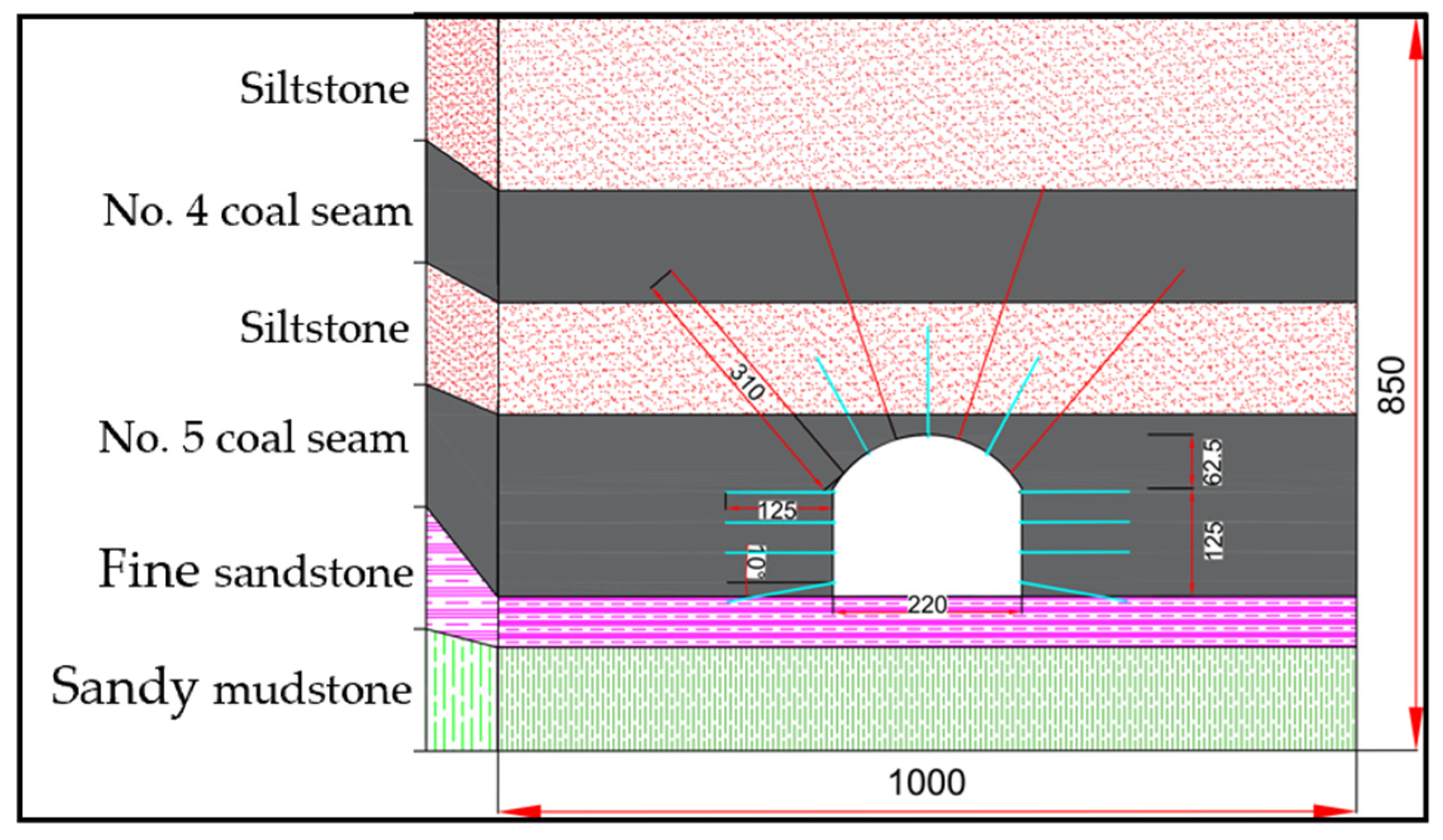
The equivalent materials consisted mainly of river sand, gypsum, and calcium carbonate, with coal powder incorporated into the coal-seam mixtures and mica powder placed at the interfaces between adjacent strata to represent weak bedding contacts. The support components were scaled according to the similarity relationships and the parameters of the prototype bolts and cables. Candidate wire materials were evaluated through laboratory pull tests, and their measured breaking loads were converted according to the force similarity relationship. Based on these tests, 1 mm diameter aluminum wires with a length of 125 mm were adopted to simulate bolts, whereas 1 mm diameter iron wires with a length of 310 mm were used to simulate cables. The configuration of the physical similarity model is shown in Figure 6.
Figure 6.
Configuration of the similarity model.
The staged loading was applied using a hydraulic loading system consisting of two upper hydraulic jacks, a manual hydraulic pump, and a steel loading plate. Roadway deformation and stress responses were monitored using an optical total station and pressure sensors, respectively. The loading sequence was designed to reproduce the stress response of the roadway surrounding rock under the combined influence of in situ stress and mining-induced disturbance. According to the burial depth and stress similarity ratio of the No. 1513 return air roadway, a total load of 65.97 kN was applied during the in situ stress stage, corresponding to loading steps 1–4. Considering the stress concentration induced by working-face extraction, the vertical load applied to the model was then gradually increased to 84.39 kN, corresponding to loading steps 5–7. This loading scheme represented the failure sequence of the roadway surrounding rock from stress redistribution to fracture propagation and final instability.
4.2. Fracture Propagation Pattern in Mining Roadways
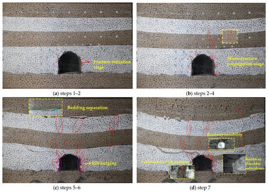
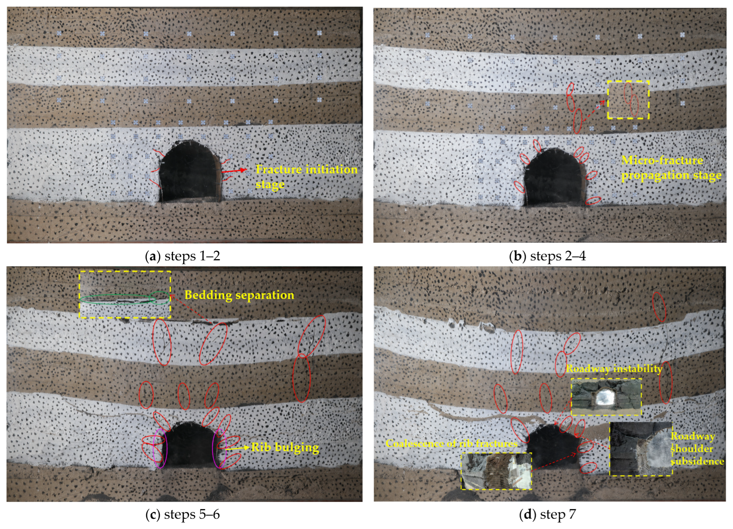
Figure 7 presents the fracture evolution of the roadway surrounding rock at different loading stages. With increasing overburden load, fractures around the No. 1513 return air roadway developed in a staged manner, including initiation, propagation, and coalescence. Fractures first initiated in stress-concentration zones, such as the ribs and roadway shoulders, then propagated toward the immediate roof and weakly supported zones, and finally coalesced with roof-spalling fractures. This process progressively weakened the structural integrity and load-bearing capacity of the surrounding rock.
Figure 7.
Fracture distribution of roadway surrounding rock at different loading stages.
Loading steps 1–2 represent the fracture-initiation stage, as illustrated in Figure 7a. At this stage, the applied overburden load rose from 1.5 MPa to 3.0 MPa. The roadway surrounding rock remained generally stable, and no obvious through-going fractures were observed in the roof or floor. Microfractures occurred only in local stress-concentration zones along the roadway ribs, with a maximum propagation depth of approximately 10 mm. Surrounding-rock failure at this stage was mainly manifested as shallow stress redistribution after excavation unloading. The number of fractures was limited, and their propagation range remained small; therefore, the overall load-bearing structure of the roadway was not significantly weakened.
Loading steps 2–4 represent the fracture-propagation stage, as illustrated in Figure 7b. When the applied overburden load rose from 3.0 MPa to 6.0 MPa, fractures became pronounced at the roadway shoulders and progressively extended toward the central part of the roof. Because the immediate roof contains the weak No. 4 coal seam, the roof system has relatively low strength and stiffness, which leads to pronounced load-induced deformation. Meanwhile, cable support exerted only limited restraint on the deep roof, so deformation compatibility between the immediate and main roofs decreased, which in turn promoted roof spalling. Fractures on both ribs continued to propagate along poorly anchored zones, and surrounding-rock failure evolved from shallow local damage to coupled roof–rib failure.
Loading steps 5–7 correspond to the fracture-coalescence stage. During loading steps 5–6, fractures at the roadway shoulders continued to propagate toward the immediate roof and weak interlayers, and local fractures began to coalesce with roof-separation fractures. Rib fractures further developed along weakly supported zones, as shown in Figure 7c. When loading reached step 7, roof fractures, shoulder fractures, and rib fractures further coalesced. The immediate roof underwent more severe subsidence, and fractured coal masses in both ribs were squeezed into the roadway opening. As a result, the roadway cross-section contracted significantly, as shown in Figure 7d. At this stage, the coordinated bearing effect among bolts, cables, and surrounding rock weakened, and failure of the surrounding rock evolved from local fracture propagation to overall instability.
The physical similarity simulation results indicate that fracture evolution in the No. 1513 return air roadway is distinctly progressive. Overall, the fracture evolution follows a progressive sequence of “fracture initiation in the ribs—propagation toward the roadway shoulder—roof–shoulder–rib coalescence.” Because the weak No. 4 coal seam is embedded in the roof, load sharing among roof strata is weakened, increasing the likelihood of roof separation and fracture propagation. Meanwhile, the low strength of the rib coal and the presence of poorly supported zones promote the continuous inward propagation of rib fractures, which eventually coalesce with fractures in the roadway shoulders and roof. This process indicates that surrounding-rock instability in mining roadways developed in three-soft coal seams is not caused by isolated local failure. Instead, it results from the coupled effects of weak-interlayer-controlled roof separation, shoulder-fracture propagation, and rib-coal extrusion, providing a basis for subsequent numerical simulation and support-parameter optimization.
5. Numerical Simulation of Surrounding-Rock Deformation in Mining Roadways
5.1. Numerical Model Development
The physical similarity simulation revealed the progressive evolution of fractures in the No. 1513 return air roadway, characterized by initiation in the ribs, propagation toward the roadway shoulders, and subsequent roof–rib coalescence. To examine the roadway surrounding rock response to mining-induced disturbance, FLAC3D was used to establish a three-dimensional numerical model for stress, displacement, and plastic-zone analysis. The simulation followed three stages: development of the No. 1513 return air roadway, mining of the No. 1512 working face, and subsequent advance of the No. 1513 working face.
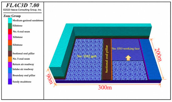
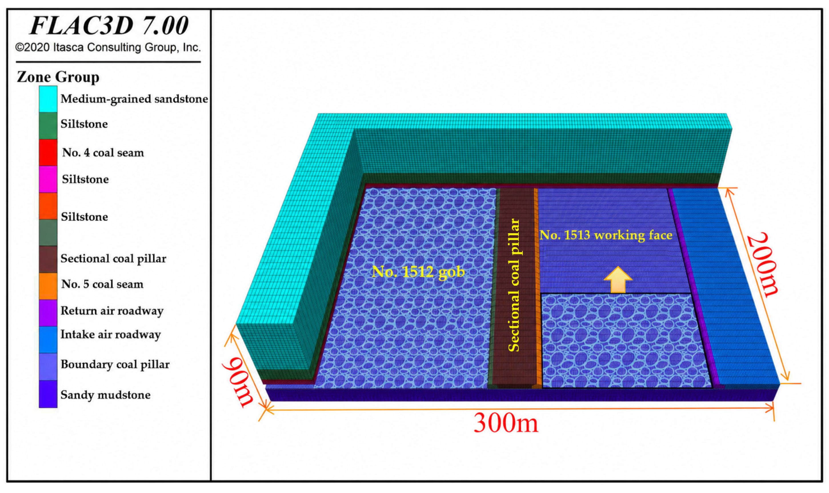
The computational domain was configured to reproduce the geological setting of the No. 1513 working face, roadway geometry, and mining arrangement. The domain extended 300 m × 200 m × 90 m. A locally refined zoning strategy was adopted, with a denser mesh around the No. 1513 return air roadway and a coarser mesh in regions farther from the roadway to ensure adequate resolution of the surrounding-rock response while maintaining computational efficiency. The final model comprised 2,157,260 zones and 1,248,542 grid points. The No. 1512 and No. 1513 working faces were arranged on the left and right sides of the No. 1513 return air roadway, respectively. A 20 m-wide sectional coal pillar was included in the model. The base was fixed against displacement, normal movement was restricted along the lateral boundaries, and an equivalent overburden load was applied to the upper boundary. Coal and rock strata were represented by the Mohr–Coulomb constitutive model, whereas bolts and cables were simulated using cable elements. The model configuration and the mechanical properties assigned to the coal–rock mass are provided in Figure 8 and Table 2, respectively.
Figure 8.
Numerical calculation model.
Table 2.
Mechanical parameters of the coal–rock mass.
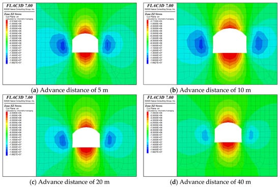
The simulation procedure was conducted according to the in situ mining sequence. First, the No. 1513 return air roadway and No. 1513 intake air roadway were excavated at intervals of 10 m, and bolts and cables were installed according to the original support parameters. Subsequently, the No. 1512 working face was extracted in 5 m increments to evaluate the response of the No. 1513 return air roadway to initial mining. The No. 1513 working face was then advanced in 5 m increments. Monitoring sections were arranged at advance distances of 5 m, 10 m, 20 m, and 40 m from the working face to examine stress redistribution, displacement variation, and plastic-zone development during secondary mining.
5.2. Mining-Induced Deformation and Failure of Roadway Surrounding Rock
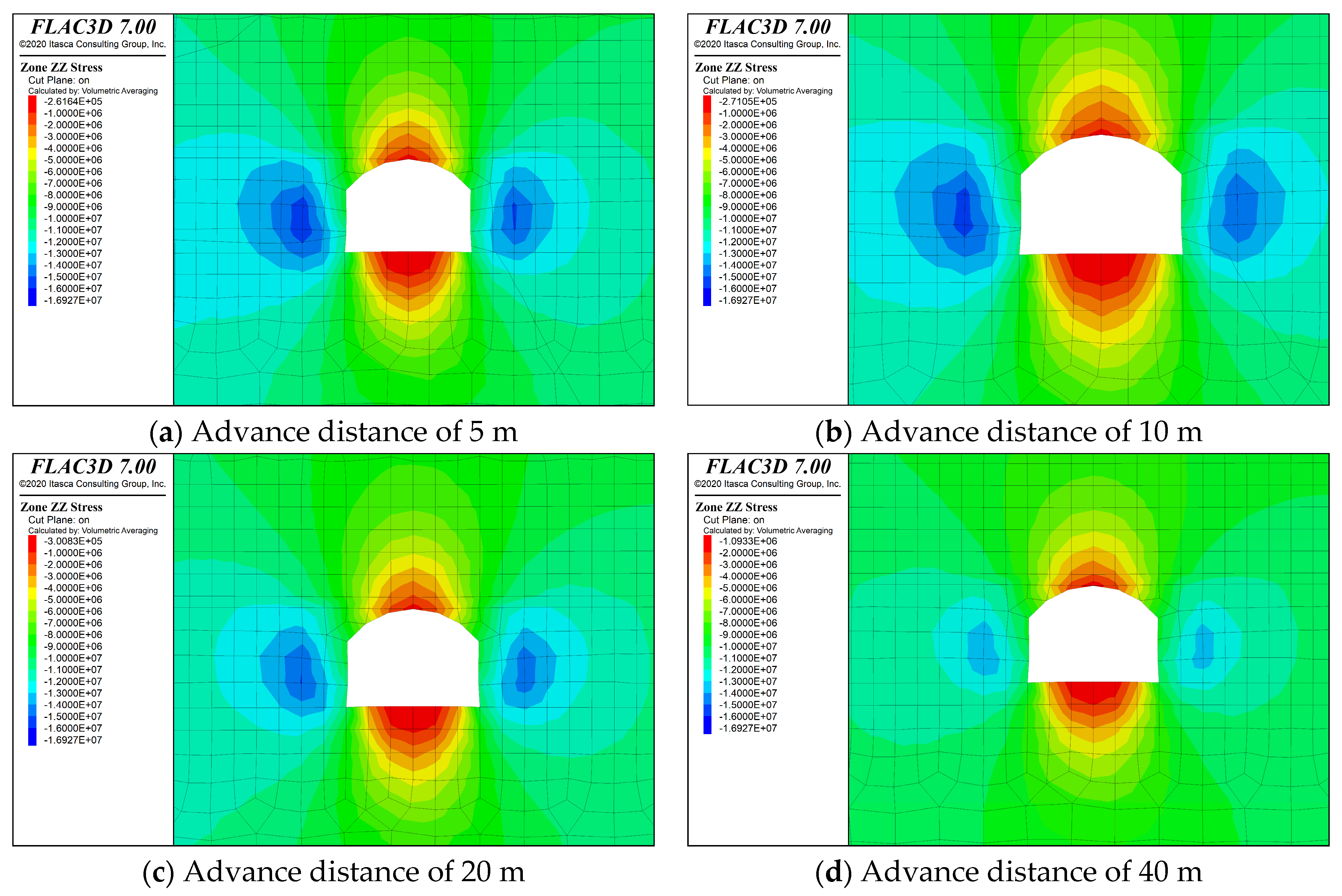
Lateral abutment loading generated by extraction of the adjacent No. 1512 working face acted on the No. 1513 return air roadway, producing stress redistribution in the surrounding rock. Figure 9 shows that vertical stress was more concentrated in the pillar-side rib than in the solid-coal rib. The peak vertical stress reached approximately 16.15 MPa in the pillar-side rib and approximately 15 MPa in the solid-coal rib. The main stress-concentration region occurred about 2 m inward from the coal wall. Relative to the roadway excavation stage, initial mining transformed the roadway surrounding rock from a nearly symmetric loading condition to an asymmetric one, and the pillar-side rib became the dominant bearing zone.
Figure 9.
Vertical stress distribution of roadway surrounding rock at different advance distances.
During initial mining, roadway deformation intensified, accompanied by the onset of plastic-zone expansion. Maximum calculated subsidence was approximately 125 mm in the immediate roof and 50 mm in the main roof. The pillar-side rib moved laterally by approximately 60 mm, while the solid-coal rib displaced by approximately 34 mm, indicating a clear asymmetric deformation response under mining-induced loading. Plastic yielding was concentrated toward the roof, floor, and pillar-side rib. The roof plastic zone developed upward to a maximum height of about 2.5 m, and floor failure reached a similar depth of approximately 2.5 m. At this stage, damage was governed mainly by pillar-side stress concentration, roof subsidence, and shallow plastic yielding. Large-scale through-going instability had not yet formed.
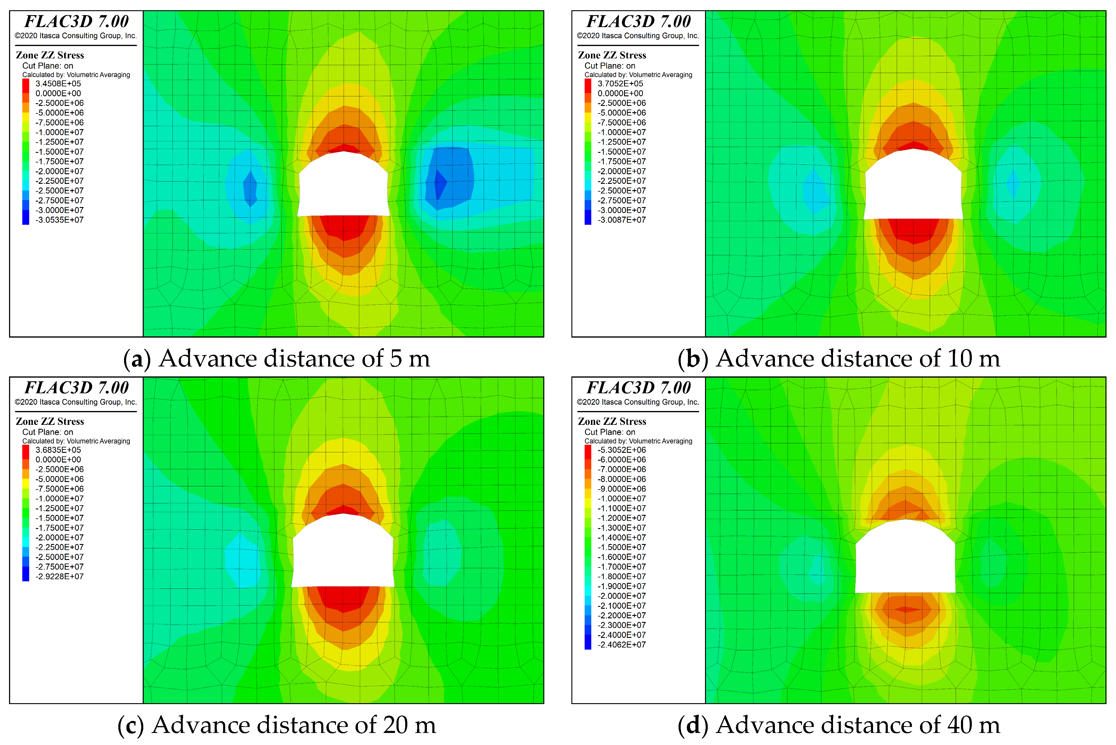
Following extraction of the No. 1513 working face, the No. 1513 return air roadway was subjected to intensified disturbance associated with secondary mining. Stress concentration within the surrounding rock increased markedly. Figure 10 shows a rapid increase in vertical stress within 5–10 m ahead of the working face, affecting both roadway ribs. Peak vertical stresses were 30.53 MPa on the solid-coal side and 27.5 MPa on the coal-pillar side. Compared with the initial mining stage, secondary mining changed the previous stress pattern, which had been characterized mainly by concentration on the pillar-side rib. Both ribs of the roadway entered zones of high stress concentration, which further aggravated damage to the surrounding rock.
Figure 10.
Vertical stress distribution around the roadway at different advance distances.
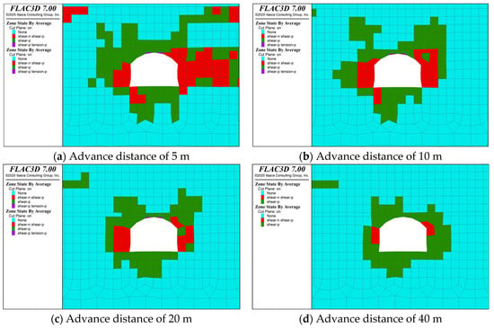
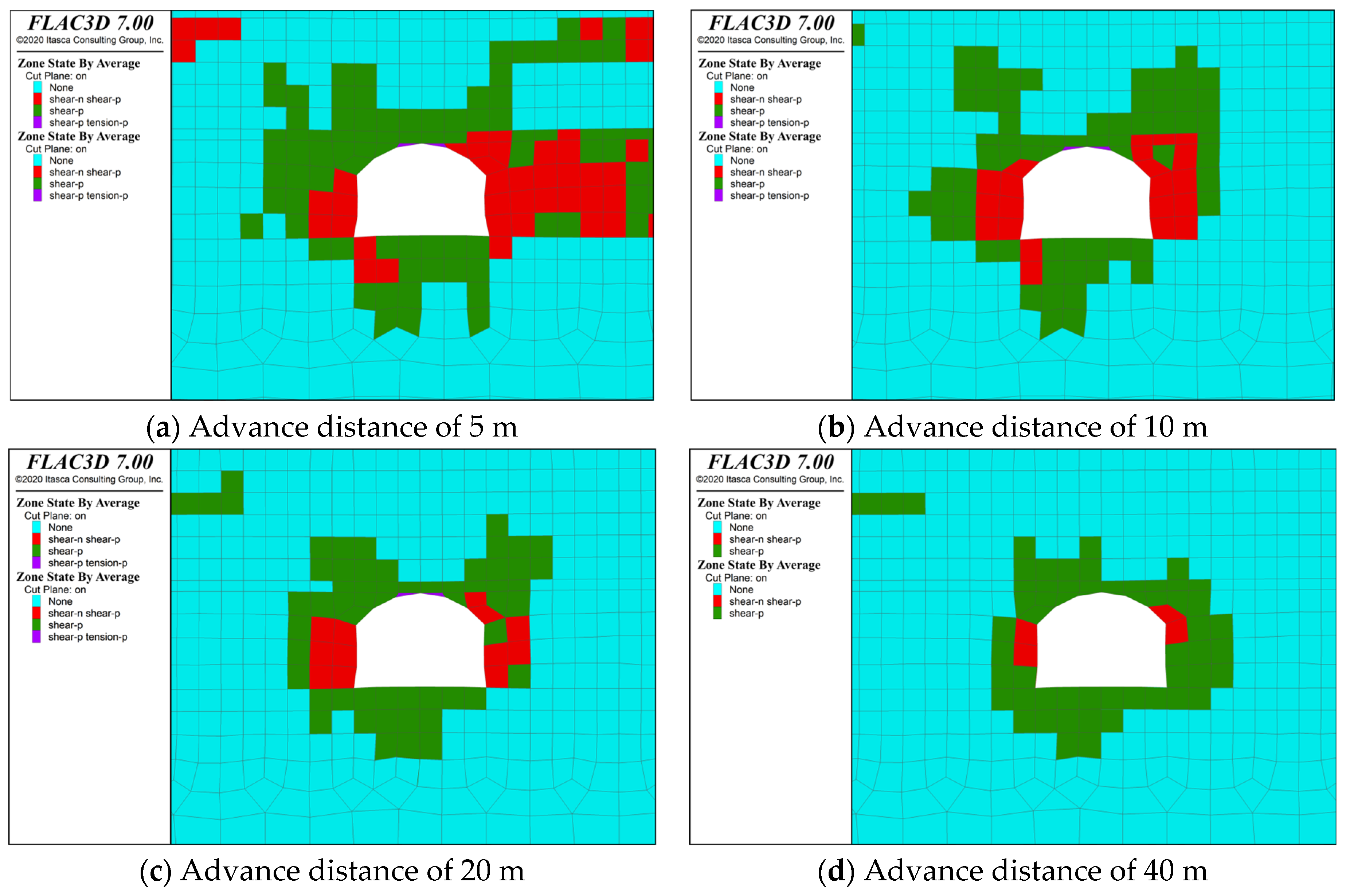
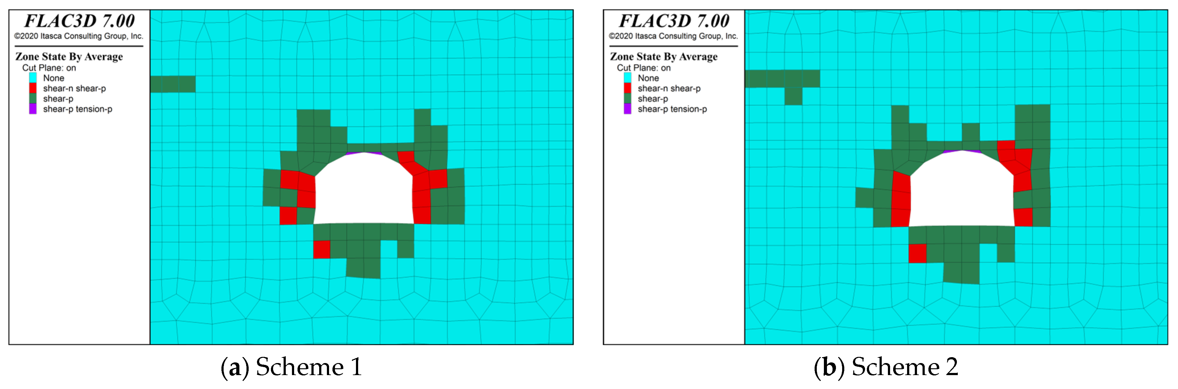
Under secondary-mining disturbance, roadway deformation intensified markedly. The roof subsidence reached a maximum of 532 mm, whereas the maximum rib convergence was 1100.5 mm. The roadway cross section contracted severely. Figure 11 shows that the roof plastic zone developed to a maximum height of 5.5 m, while the plastic zones in both ribs expanded significantly. Extensive failure occurred in the bolts and shoulder-angle cables. At this stage, surrounding-rock failure evolved from local plastic deformation after initial mining to coordinated instability of the roof, roadway shoulders, and ribs. The failure was mainly characterized by coupled mechanisms, including roof-spalling propagation, rib-coal extrusion, and support-structure failure.
Figure 11.
Plastic-zone distribution induced by secondary mining.
The simulation results indicate that the No. 1513 return air roadway experienced cumulative deformation and failure under mining-induced stress. During initial mining, stress became concentrated in the pillar-side rib, accompanied by localized plastic-zone expansion. Secondary mining further intensified stress concentration in both ribs, deep roof damage, and support-structure failure.
These numerical characteristics are in good agreement with those observed in the physical similarity model. With a geometric scale factor of Cl = 20, the maximum roof displacement of approximately 26–27 mm measured at the final loading stage of the physical model corresponds to a prototype-equivalent displacement of approximately 520–540 mm, which is close to the maximum roof subsidence of 532 mm obtained from FLAC3D.
Consistency was also observed in the spatial distribution of surrounding-rock failure. In the physical model, fractures progressively propagated from the ribs toward the roadway shoulders and roof and eventually coalesced, whereas the numerical model showed pronounced plastic-zone development in the ribs, roadway shoulders, and deep roof under secondary mining. The present results are consistent with previous observations that repeated mining disturbance progressively intensifies stress redistribution, surrounding-rock deformation, and fracture development in mining roadways [2,3,8,9]. Previous studies have also shown that weak roof interlayers disrupt coordinated load transfer between adjacent strata and promote roof separation [10,22]. Against this background, the present study further indicates that, under three-soft coal-seam conditions, roof separation, shoulder-fracture propagation, and rib deformation interact progressively rather than occurring as isolated responses, ultimately forming a spatially coupled roof–shoulder–rib failure process. Taken together, the physical and numerical simulations consistently indicate that the deep roof, roadway shoulders, and middle sections of the ribs are the principal deformation and failure zones under secondary mining and should therefore be regarded as the key reinforcement zones for subsequent support optimization.
5.3. Support Optimization Scheme and Control Effect
Drawing on the theoretical analysis and the results of the physical and numerical simulations, support optimization of the No. 1513 return air roadway was focused on three critical zones: the deep roof, roadway shoulders, and ribs. Two candidate schemes were therefore developed from the original support system to progressively strengthen these weak regions.
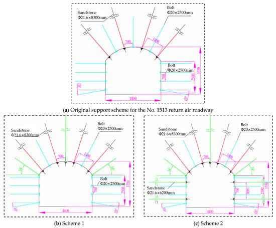
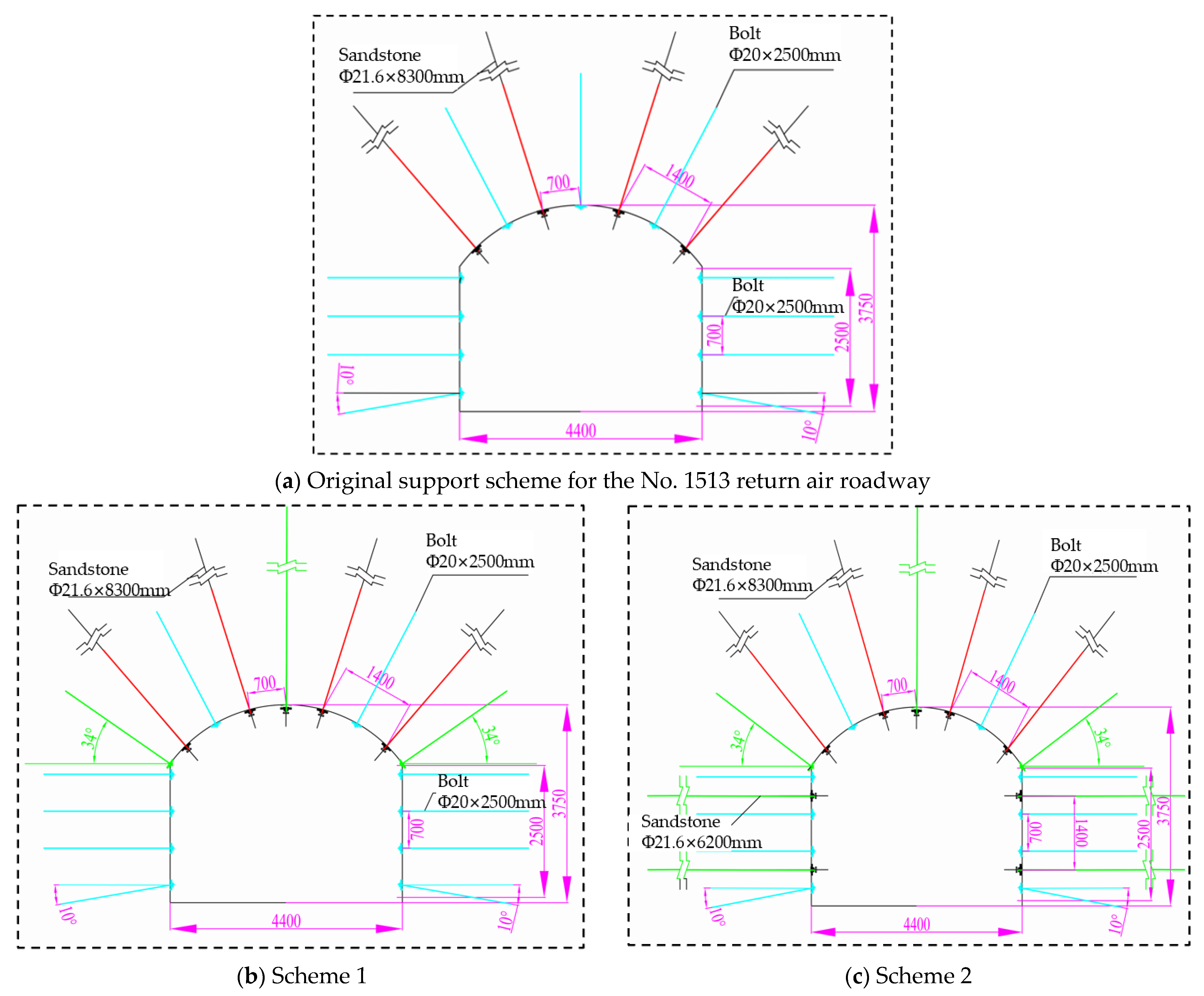
The original support system consisted of 11 Φ20 mm × 2500 mm roof-and-rib bolts and four Φ21.6 mm × 8300 mm roof cables. Scheme 1 primarily enhanced roof support by increasing the number of roof cables to five. Scheme 2 further extended the reinforcement from the roof to the roadway shoulders and ribs to establish a coordinated roof–shoulder–rib support system. In Scheme 2, 14 Φ20 mm × 2500 mm bolts were installed in the roof and ribs, with each bolt anchored using a Z2360 resin cartridge and providing an anchorage force of no less than 125 kN. Five Φ21.6 mm × 8300 mm cables were installed in the roof, and four additional Φ21.6 mm × 6200 mm cables were installed in the ribs. The cable spacing was 1000 mm × 1600 mm, and Z2360 resin cartridges were also used for cable anchorage. The layouts of the three support configurations are shown in Figure 12.
Figure 12.
Schematic diagrams of different support schemes.
The simulation results for different support schemes show that roadway surrounding-rock deformation was controlled to varying degrees after optimization. Under the initial mining condition, Scheme 1 limited the maximum roof subsidence to 156 mm, which was 12% lower than that of the original scheme. The maximum rib convergence under Scheme 1 was 134 mm, corresponding to a 6% decrease. Scheme 2 further reduced the roof subsidence and rib convergence to 118 mm and 114 mm, respectively, showing better deformation control than Scheme 1. This comparison suggests that increasing roof-cable support alone can mitigate roof deformation but provides limited control over rib deformation. In contrast, coordinated roof–rib reinforcement provides a more effective means of enhancing roadway stability.
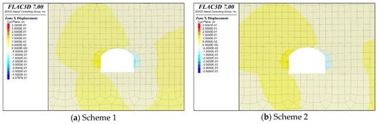
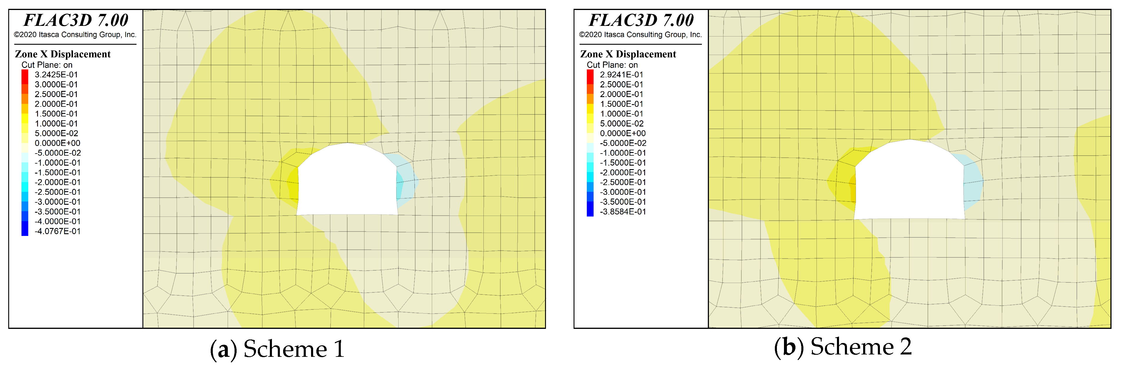
Under secondary-mining conditions, roadway deformation intensified, making the differences among support schemes more evident. Scheme 1 limited roof subsidence to a maximum of 330 mm, which was 10.8% lower than that of the original scheme. The corresponding maximum rib convergence was 256 mm, corresponding to a 12.1% decrease. In Scheme 2, roof subsidence and rib convergence were further reduced to 315 mm and 201 mm, respectively. Compared with Scheme 1, Scheme 2 reduced the maximum rib convergence by approximately 21.5%. The horizontal and vertical displacement distributions indicate that Scheme 2 effectively limited rib convergence and roof subsidence, thereby improving control of the roadway cross-section, as illustrated in Figure 13 and Figure 14.
Figure 13.
Nephograms of roadway horizontal displacement under different support schemes.
Figure 14.
Nephograms of roadway vertical displacement under different support schemes.
The comparison among the candidate schemes shows that roof reinforcement alone can reduce roof subsidence but provides limited control of large rib deformation. For three-soft coal-seam roadways, the reinforcement layout should be matched to the dominant deformation and failure zones of the surrounding rock [23]. Scheme 2 therefore extended reinforcement from the roof to the roadway shoulders and ribs, forming a coordinated roof–shoulder–rib support system. It included 14 Φ20 mm × 2500 mm bolts in the roof and ribs, with an anchorage force of no less than 125 kN, five Φ21.6 mm × 8300 mm roof cables, and four additional Φ21.6 mm × 6200 mm rib cables arranged at 1000 mm × 1600 mm spacing.
Scheme 2 was selected by jointly considering deformation control, roadway stability, and subsequent maintenance demand. Under initial mining, the maximum roof subsidence and rib convergence were reduced to 118 mm and 114 mm, respectively; under secondary mining, they were controlled at 315 mm and 201 mm, while the plastic failure zones in the roof and ribs were further reduced. These results indicate that the coordinated support more effectively controlled the principal failure zones and reduced the potential for support damage and repeated roadway maintenance.
Scheme 2 was subsequently implemented in the No. 1518 return air roadway for field verification. Four monitoring stations (B1–B4) were arranged to monitor roof separation and roadway convergence, with roof-to-floor and rib convergence measured using the cross-measurement method. The field results showed a maximum roof separation of approximately 46 mm. The maximum roof-to-floor convergence and rib convergence were 284 mm and 261 mm, respectively, representing reductions of 73% and 55% relative to the original support system. These field observations further verified the effectiveness of the coordinated roof–shoulder–rib support in controlling mining-induced roadway deformation.
6. Conclusions
- (1)
- Based on fracture mechanics and composite beam theory, a mechanical model was developed to describe unstable microcrack propagation in the ribs of three-soft coal-seam roadways and slip deformation in roofs containing weak interlayers. The critical conditions for coalescence instability of composite fractures under multi-fracture interaction were identified. The separation displacement of the weak interlayer inside and outside the anchorage zone was quantified under mining-induced loading. The calculations showed that effective anchorage reduced the maximum weak-interlayer separation displacement from 78 mm to 20 mm, corresponding to a reduction of approximately 74%. This result demonstrates that anchorage into stable strata is essential for maintaining roadway-roof stability.
- (2)
- The physical similarity simulation shows that three-soft coal-seam mining roadways undergo distinct progressive failure under mining-induced stress. The weak No. 4 coal seam embedded in the roof significantly weakens load sharing among the roof strata. Fracture evolution follows a three-stage progressive pattern: local initiation in the ribs, propagation toward the roadway shoulders, and coalescence between roof-separation fractures and rib fractures. During mining, subsidence and separation of the weak roof interact with inward extrusion of fractured rib coal, ultimately inducing shear failure of the integrated bearing structure.
- (3)
- Numerical modeling captured stress redistribution and plastic-zone development in the roadway subjected to repeated mining disturbances. During initial mining, the pillar-side peak vertical stress reached 16.15 MPa, accompanied by asymmetric deformation of the surrounding rock under biased loading. During secondary mining, the peak stresses reached 30.53 MPa in the solid-coal rib and 27.5 MPa in the pillar-side rib, while the roof plastic zone propagated upward to 5.5 m. According to the identified instability mechanism, a coordinated roof–shoulder–rib reinforcement scheme was proposed, with emphasis on “deep roof anchorage–roadway-shoulder reinforcement–high-strength rib reinforcement.” Field verification in the No. 1518 return air roadway showed that the optimized scheme reduced the maximum roof-to-floor convergence by 73% and rib convergence by 55% relative to the original support scheme. These results demonstrate the effectiveness of the coordinated roof–shoulder–rib reinforcement concept and indicate its practical relevance to three-soft coal-seam roadways characterized by weak roof interlayers and pronounced deformation under repeated mining disturbance, providing a basis for identifying key reinforcement zones and optimizing support configurations under comparable geological and mining conditions.
Author Contributions
Data curation, J.Z., Q.W. and L.Z.; Methodology, T.Y. and S.Z.; Software, S.Z. and Y.Z.; Validation, S.Z. and J.S.; Writing—original draft, S.Z.; Writing—review and editing, T.Y. All authors have read and agreed to the published version of the manuscript.
Funding
This research was funded by the National Natural Science Foundation of China, grant number 52004200.
Institutional Review Board Statement
Not applicable.
Informed Consent Statement
Not applicable.
Data Availability Statement
The data used in this study are included in the article. Further details are available from the corresponding author upon reasonable request.
Acknowledgments
The authors acknowledge the financial support from the funding agency.
Conflicts of Interest
The authors declare no conflicts of interest.
References
- Li, W.; Liu, J.; Chen, L.; Zhong, Z.; Liu, Y. Roadway support in deep “three-soft” coal seam: A case study in Yili Mining Area, China. Shock Vib. 2021, 2021, 8851057. [Google Scholar] [CrossRef] [Scilit]
- Yang, X.; Yang, G.; Huang, R.; Wang, Y.; Liu, J.; Zhang, J.; Hou, S. Comprehensive study on surrounding rock failure characteristics of longwall roadway and control techniques. Appl. Sci. 2021, 11, 9795. [Google Scholar] [CrossRef] [Scilit]
- Qian, D.; Deng, J.; Wang, S.; Yang, X.; Cui, Q.; Li, Z.; Jin, S.; Liu, W. Deformation characteristics and control countermeasures for surrounding rock of deep roadway under mining disturbance: A case study. Shock Vib. 2022, 2022, 9878557. [Google Scholar] [CrossRef] [Scilit]
- An, Y.; Zhang, N.; Zhao, Y.; Xie, Z. Field and numerical investigation on roof failure and fracture control of thick coal seam roadway. Eng. Fail. Anal. 2021, 128, 105594. [Google Scholar] [CrossRef] [Scilit]
- Zhou, K.; Yu, F.; Tan, Y.; Guo, W.; Zhao, T. Study on failure behaviors and control technology of surrounding rock in a weakly cemented soft rock roadway: A case study. Front. Earth Sci. 2023, 11, 1153753. [Google Scholar] [CrossRef] [Scilit]
- Li, J.; Li, Y.; Xie, Z.; Zhang, N.; Guo, F.; Chen, Q.; Liu, S. Study on deformation and instability characteristics and control technology of deep soft rock roadway with strong mining. SN Appl. Sci. 2023, 5, 292, Correction in SN Appl. Sci. 2023, 5, 304. [Google Scholar] [CrossRef] [Scilit]
- Zhang, J.; Wu, H.; Zhuo, Q.; He, Y.; Gao, S.; Sun, J.; Zhang, Y.; Pang, H.; Jia, Z. Study on reasonable optimization of coal pillar in “three soft” coal seam section. China Min. Mag. 2025, 34, 126–136. (In Chinese) [Google Scholar]
- Xiong, Y.; Kong, D.; Cheng, Z.; Wen, Z.; Ma, Z.; Wu, G.; Liu, Y. Instability control of roadway surrounding rock in close-distance coal seam groups under repeated mining. Energies 2021, 14, 5193. [Google Scholar] [CrossRef] [Scilit]
- Shang, Y.; Kong, D.; Pu, S.; Xiong, Y.; Li, Q.; Cheng, Z. Study on failure characteristics and control technology of roadway surrounding rock under repeated mining in close-distance coal seam. Mathematics 2022, 10, 2166. [Google Scholar] [CrossRef] [Scilit]
- Chang, J.; Guo, Y.; Wu, B.; Shi, W.; Qi, C.; Wang, H. Study on failure characteristics and control of roof separation with weak interlayer of deep gob-side entry driving. Coal Sci. Technol. 2024, 52, 88–102. (In Chinese) [Google Scholar]
- Fu, Y.; Wang, T.; Sun, Z.; Zheng, J. Layered control technology and practice of long and short anchor cable in composite soft rock roadway. J. Min. Saf. Eng. 2021, 38, 237–245. (In Chinese) [Google Scholar]
- Xu, Y.; Liu, D.; Wu, X.; Cao, Z.; Gao, Y.; Zhang, R.; Zhou, Z.; Zhou, B.; Xu, M.; Zhang, H. Surrounding rock control technology by pressure relief stress transfer reinforce in three-soft coal seam under strong dynamic pressure. Coal Sci. Technol. 2021, 49, 30–37. (In Chinese) [Google Scholar]
- Kaiser, P.K.; Moss, A. Deformation-based support design for highly stressed ground with a focus on rockburst damage mitigation. J. Rock Mech. Geotech. Eng. 2022, 14, 50–66. [Google Scholar] [CrossRef] [Scilit]
- Cheng, L.; Kang, H.; Jiang, P.; Li, W.; Yang, J.; Zheng, Y.; Yi, K. Deformation and failure characteristics and control technology of surrounding rocks in deeply gob-side entry driving. J. Min. Saf. Eng. 2021, 38, 227–236. (In Chinese) [Google Scholar]
- Wu, J.; Jiao, J.; Zhou, S. Controlling large deformations in soft rock roadways with integrated anchor shotcrete and grouting techniques. Sci. Rep. 2024, 14, 28339. [Google Scholar] [CrossRef] [Scilit] [PubMed]
- Li, W.; Guo, Y.; Liu, X.; Du, F.; Li, G.; Ma, Q. Failure mechanisms and reinforcement support of soft rock roadway in deep extra-thick coal seam: A case study. Eng. Fail. Anal. 2024, 165, 108745. [Google Scholar] [CrossRef] [Scilit]
- Wang, W.; Fan, L.; Zhao, Z.; Han, S. Research progress of support theory and technology of the roadway surrounding rock based on the plastic zone control. J. China Coal Soc. 2024, 49, 320–336. (In Chinese) [Google Scholar]
- Xie, S.; Li, H.; Chen, D.; Feng, S.; Yang, J.; Ma, X.; Jiang, Z.; Xing, S. Research on the control technology and key parameters of external anchor-internal unloading of surrounding rock during gob-side entry driving under severe mining of 1000-m-deep mine. Rock Mech. Rock Eng. 2024, 57, 2913–2932. [Google Scholar] [CrossRef] [Scilit]
- Dyskin, A.V.; Germanovich, L.N. Model of rockburst caused by cracks growing near free surface. In Proceedings of the 3rd International Symposium on Rockbursts and Seismicity in Mines, Kingston, ON, Canada, 16–18 August 1993; Young, R.P., Ed.; A.A. Balkema: Rotterdam, The Netherlands, 1993; pp. 169–174. [Google Scholar]
- Irwin, G.R. Analysis of stresses and strains near the end of a crack traversing a plate. J. Appl. Mech. 1957, 24, 361–364. [Google Scholar] [CrossRef] [Scilit]
- Nemat-Nasser, S.; Horii, H. Compression-induced nonplanar crack extension with application to splitting, exfoliation, and rockburst. J. Geophys. Res. Solid Earth 1982, 87, 6805–6821. [Google Scholar] [CrossRef] [Scilit]
- Liu, Y.; Zheng, P.; Xu, L.; Li, W.; Sun, Y.; Sun, W.; Yuan, Z. Mechanism of roof deformation and support optimization of deeply buried roadway under mining conditions. Appl. Sci. 2022, 12, 12090. [Google Scholar] [CrossRef] [Scilit]
- Xie, X.; Liu, H.; Fang, X.; Yang, J.; Liu, J.; Liang, M.; Wu, G. Deformation mechanism and control technology of surrounding rock of three-soft coal roadways under high horizontal stress. Energies 2023, 16, 728. [Google Scholar] [CrossRef] [Scilit]


Disclaimer/Publisher’s Note: The statements, opinions and data contained in all publications are solely those of the individual author(s) and contributor(s) and not of MDPI and/or the editor(s). MDPI and/or the editor(s) disclaim responsibility for any injury to people or property resulting from any ideas, methods, instructions or products referred to in the content. |
© 2026 by the authors. Licensee MDPI, Basel, Switzerland. This article is an open access article distributed under the terms and conditions of the Creative Commons Attribution (CC BY) license.