Abstract
Roadways driven along the floor of thick coal seams, while retaining the top coal, form “thick coal seam floor roadways.” These large-section roadways feature a composite coal-rock roof and weak coal ribs, leading to low overall strength and poor stability of the surrounding rock. Significant deformation and “necking” often occur, accompanied by roof falls and rib spalling, which are exacerbated under high stress or adverse geology, threatening mine safety and production. In this study, the 2201 haulage gateway in Yingpanhao Coal Mine is investigated to address surrounding rock control in such deep roadways. Using field investigation, theoretical analysis, numerical simulation, and similar simulation tests, the failure mechanisms of ribs and roofs are analyzed. Rib failure is characterized by tensile fracture in the shallow zone, splitting failure in the medium-depth zone, and incomplete conjugate shear in the deep zone. Corresponding mechanical models are established, and a method for calculating total rib failure depth—combining tensile/splitting and shear failure depths—is proposed, along with a bolt length design formula. Based on this, a synergistic roof-and-rib support technology is developed. The failure mechanism and optimal support scheme are validated through simulation tests and successfully applied in the field, demonstrating satisfactory performance. The findings provide a valuable reference for support design in similar mining roadways.
1. Introduction
Roadways in thick coal seams are typically driven along the seam floor while retaining the top coal, thereby forming thick coal seam floor roadways. These roadways feature a large cross-sectional area. The roof consists of a coal-rock composite structure, and both ribs are composed of weak coal. As the top coal and ribs form a continuous entity, the overall strength of the surrounding rock is low and its stability is poor. Consequently, significant deformation and cross-sectional “necking” occur during both roadway development and panel extraction. Moreover, incidents of localized roof falls and rib spalling remain frequent. These issues are particularly pronounced under conditions such as great depth, high tectonic stress, low coal strength with variable mechanical properties, and adverse geological environments, posing a serious threat to both mine safety and high-efficiency production [1,2]. Recent studies on surrounding rock behavior under large mining height and in mining-induced subsidence zones further underscore the complexity of these challenges [3,4].
To date, numerous scholars, both domestically and internationally, have conducted extensive research on the deformation and failure mechanisms of roadway surrounding rock in coal mines, yielding important theoretical and applied results. Foundational work in rock mechanics and rock-mass classification provides the theoretical basis for understanding excavation-induced responses in coal roadways: classical formulations of stress–strain behaviour around underground openings, the empirical rock-mass criteria and classification systems remain essential for interpreting rib and roof failure modes. Building on these fundamentals, Wang et al. [5] solved the stress equilibrium differential equation to determine the stress at the coal seam interface and the width of the limit-equilibrium zone, and performed sensitivity analysis of the main controlling parameters. Zhang et al. [6] emphasized that coal-rib deformation in extraction roadways is dominated by coal mass loosening and extrusion along the seam interface, and that these two processes interact and reinforce one another. Field-observations and laboratory/numerical studies have further clarified typical rib failure patterns—spalling, shear/sliding, splitting and arch-type collapse—and their dependence on in situ stress, rock mass quality and seam properties; Xiang et al. [7] reported tensile initiation near the wall with transition to shear failure at greater depth, while Li et al. [8] identified compression-shear and splitting as prevalent rib mechanisms in weak coal masses. To address severe upper-rib spalling and support challenges in roof-driven roadways, Xue et al. [9,10] developed a Bishop-slice based mechanical model to evaluate upper-rib instability and derived a practicable safety-factor expression, which was validated in field applications. Recent reviews and field studies have synthesized these observations and recommended integrated approaches combining empirical classification, limit-equilibrium analysis and modern numerical simulation for rib control and support design.
However, despite these significant advances, systematic research specifically targeting the unique challenges of deep thick coal seam floor roadways remains relatively limited. Despite significant progress in surrounding rock control for coal roadways, systematic research on deep thick coal seam floor roadways remains scarce. Existing studies primarily focus on single failure modes or roof control separately, often lacking an in-depth investigation of the critical interaction mechanism between the roof and ribs. To bridge this gap, a novel combined “H-shaped and Y-shaped” failure mechanism model for the ribs is established in this study, which more accurately reflects the progressive failure from shallow tensile splitting to deep shear. Furthermore, a comprehensive method for calculating the total rib failure depth is proposed, integrating both tensile/splitting and shear failure zones, leading to a new design formula for bolt length. Most importantly, moving beyond traditional isolated support approaches, a rib-roof synergistic support theory and technology are developed. The superiority of this approach is validated through simulations and field application. Compared with traditional support methods, the proposed technology achieved a reduction in roadway deformation by 58.7% and a decrease in maintenance costs by 32% in engineering practice at a depth of 722 m. These outcomes demonstrate a significant enhancement in both the stability and economic efficiency of roadways in deep thick coal seams.
The challenges associated with surrounding rock control in deep thick coal seam floor roadways are addressed in this paper. An in-depth investigation into the deformation and failure mechanisms of the surrounding rock in such roadways is conducted. Based on these findings, a targeted roof-and-rib synergistic support theory and technology are proposed and implemented in field applications. The research outcomes presented herein can provide valuable references for the selection of support technologies and corresponding engineering parameters for surrounding rock control in floor roadways under similar geological conditions.
2. Engineering Overview
2.1. Working Face Overview
The Yingpanhao Coal Mine is located in Wushen Banner, southwestern Ordos City, Inner Mongolia Autonomous Region, China. The selected panel, 2201, is the first mining panel in the No. 22 mining district and also the inaugural panel for the entire mine. It exploits the No. 2-2 coal seam, with a thickness ranging from 3.16 m to 10.24 m and an average thickness of 6.30 m, adopting the fully mechanized mining method with full-seam height extraction. The dip angle of the coal seam varies from 0° to 6°, and the burial depth ranges from 660.38 m to 783.68 m, with an average depth of 722.88 m. Panel 2201 has a panel width (inclination length) of 300 m and a panel length (strike length) of 2556 m. The immediate roof consists of sandy mudstone with a thickness of 9.2 m, while the main roof is composed of sandstone, 11.34 m thick. The immediate floor is sandy mudstone, 7.2 m thick. A schematic diagram of the panel layout and the stratigraphic column are shown in Figure 1.

Figure 1.
Working face overview and stratigraphic column of rock strata.
2.2. Deformation and Failure Characteristics of Transportation Drift
The gateways of the 2201 panel were all driven along the seam floor. The haulage gateway has a width of 6.0 m and a height of 4.1 m. The original support scheme employed a combined system of rock bolts, mesh, and cable bolts. The roof was supported by eight Φ22 × 2500 mm full-length resin-grouted rebar bolts per row, spaced at 800 × 900 mm. Two Φ17.8 × 8000 mm cable bolts were installed in the middle of the roof span, spaced at 1600 × 1800 mm. Each rib was supported by five Φ20 × 2200 mm high-strength left-hand threaded steel bolts, spaced at 800 × 900 mm. The original support pattern is illustrated in Figure 2.
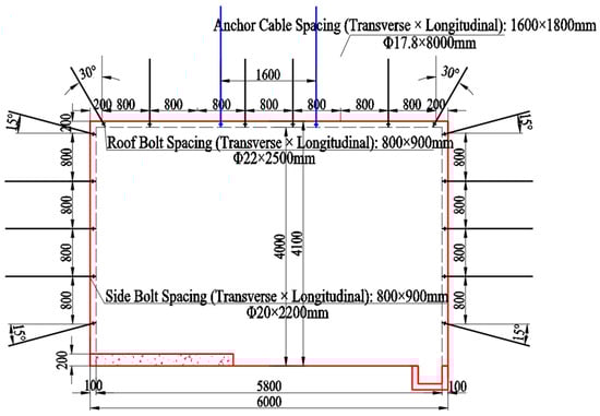
Figure 2.
Original support pattern of roadway.
Prior to the extraction of the 2201 panel, the haulage gateway was primarily affected by mechanized driving operations, causing mechanical disturbance-induced fracturing in the surrounding coal and rock, particularly in the upper soft coal sections of the ribs where there were slabbing and fragmentation, leading to a high risk of collapse. This was followed by similar layered fracturing developing in the middle-upper sections of the ribs, presenting as temporarily stable spalling conditions, while the roof showed no significant abnormalities. After support installation, the surrounding rock initially maintained good overall stability; however, over time, substantial deformation and severe failure occurred. The layered coal slabs in the middle-upper ribs fractured and underwent bulking deformation, causing the metal mesh and steel ladder beams to be pushed out and even ruptured (or torn), forming large bulges. Simultaneously, severe bursting and buckling occurred in the middle section of the ribs, resulting in the entire coal rib assuming a distinct “arched” shape that posed a major threat to subsequent gateway functionality and panel safety extraction, as shown in Figure 3. Detailed field measurements prior to support optimization revealed the quantitative severity of these failures. The rib convergence (horizontal displacement) reached 450–510 mm, with the most severe bulging deformation occurring in the middle-upper section of the ribs, where the displacement exceeded 250 mm. The depth of the visible spalling and fragmentation zone (“H-shaped” failure) ranged from 0.8 to 1.2 m. Furthermore, roof-to-floor convergence was measured at 120–140 mm, and roof separation monitoring indicated a delamination depth within the top coal of up to 0.6 m. These deformation values far exceeded the typical allowable limits for safe mining operations in such roadways, which are generally considered to be 200 mm for rib convergence and 100 mm for roof-to-floor convergence.
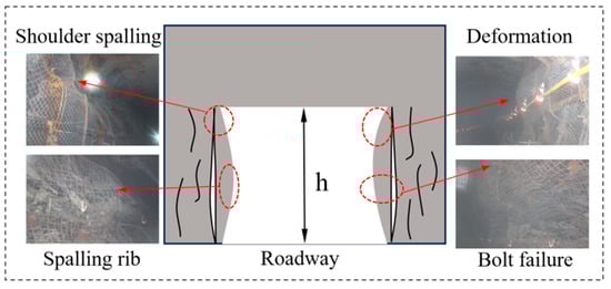
Figure 3.
Deformation and failure modes of haulage roadway.
As illustrated in the figure above, the deformation and failure characteristics of the deep thick coal seam floor roadway primarily manifest as follows: the middle-upper sections of the ribs experience spalling and collapse or temporary self-stabilization, while the middle section exhibits pronounced block-shaped spalling, fragmentation, bulking, and buckling. The roof remains generally stable; however, the top coal undergoes bending and delamination, posing a potential roof fall hazard. The support structure is either partially ineffective or inadequately designed, necessitating secondary reinforcement or roadway rehabilitation.
3. Mechanism of Deformation and Failure of Surrounding Rock of Floor-Following Drift in Thick Coal Seam
3.1. Analysis of Shear Failure and Sliding of Drift Sidewall
Prior to roadway excavation, the coal mass in the rib is in a triaxial stress state. During excavation-induced unloading, the coal rib first undergoes a radial dynamic unloading stage. Under rapid unloading, the coal-rock mass primarily experiences brittle failure [11,12,13], characterized by the continuous initiation, propagation, and connection of longitudinal cracks perpendicular to the unloading direction from the rib corner. This results in splitting failure in the shallow zone of the coal rib, forming an “H”-shaped failure zone. The depth of this unloading-induced splitting zone (Lp) is governed by the unloading rate, the tensile strength of the coal, and the magnitude of the pre-excavation horizontal stress (σ3). This constitutes a dynamic unloading failure mechanism, as illustrated in Figure 4a.
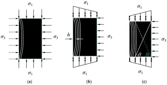
Figure 4.
Deformation and failure mechanism of roadway wall rock. (a) Dynamic unloading failure; (b) Uniaxial compression splitting failure; (c) Incomplete conjugate shear failure.
The splitting failure in the shallow zone, combined with further splitting in the medium-deep zone induced by uniaxial compression (due to stress concentration after excavation), collectively forms a continuous splitting failure belt within the shallow to medium-deep areas of the rib. The vertical fracture surfaces are arranged in sets, presenting a distinct “H”-shaped failure pattern. This failure mode is primarily a function of the tangential stress concentration and the tensile/shear strength anisotropy of the coal. It constitutes a uniaxial compression-induced splitting failure mode, as illustrated in Figure 4b.
When compressive-shear failure occurs in the deep zone of the coal rib, an “X”-shaped conjugate shear failure surface tends to develop. Under the influence of tangential stress concentration, two intersecting failure surfaces form, both inclined at an angle θ to the horizontal. This angle θ is intrinsically related to the internal friction angle (φ) of the coal mass, approximately by θ = 45° + φ/2, based on Mohr–Coulomb failure theory. The transition to this deep shear failure occurs when the shear stress, resulting from the combined effect of vertical stress (σ1) and the confinement (effective σ3) provided by the fractured medium-deep zone, exceeds the shear strength of the coal. However, due to the stable floor (providing a strong constraint and uniform stress distribution in the lower rib) and the significantly weaker upward shear driving force, the secondary failure surface in the lower section is often non-persistent. In practice, it is frequently truncated by the dominant upper shear surface [14,15]. This ultimately forms an incomplete conjugate shear failure surface, characterized as a “Y”-shaped failure zone, as shown in Figure 4c. Therefore, the geometry and extent of the deep “Y-shaped” shear zone are controlled by the stress ratio (σ1/σ3), the coal’s shear strength parameters (cohesion c and friction angle φ), and the roadway height (H).
In Figure 4c, the vertical stress on the rib can be simplified as stress concentration from the roof and floor, while the horizontal direction is constrained by the confining stress σ3 from the medium-deep layered fracture zone. The solid line represents the primary failure surface, and the dashed line denotes the secondary failure surface. The green shaded area indicates the missing or non-manifested lower section. The stability of the rib surrounding rock is primarily controlled by the shear failure mechanism of the deep coal mass.
In the analysis of slip stability, the principle of virtual work (or virtual power) is employed to conduct an energy conservation analysis of the sliding mass equilibrium [16,17,18]. The mathematical treatment and boundary condition settings follow the common practices established in the existing literature, and specific expressions tailored to this project are provided on that basis. According to the principle of virtual power, the stability of a potential sliding wedge along the failure surface with inclination angle θ is analyzed. Consider a virtual plastic flow where the wedge slides along the failure surface with a velocity v. The equilibrium condition requires that the total power expended by the external forces equals the total internal energy dissipation rate on the sliding surface.
External Power (Pext): This comprises (a) the power due to the weight of the sliding wedge and (b) the power due to the uniform roof load σ1.
(a) The weight of the wedge per unit length is (1/2)γH2cotθvsinθ. The vertical component of velocity is vsinθ. Hence, the power is (1/2)γH2cotθvsinθ.
(b) The roof load on the top surface (length H cotθ) is σ1Hcotθ. The vertical component of velocity is also vsinθ. Hence, the power is σ1Hcotθ·vsinθ.
Thus, Pext = [(1/2) γH2cotθ + σ1Hcotθ]vsinθ.
Internal Dissipation Rate (Dint): The internal energy is dissipated along the failure surface of length H/sinθ. For a Mohr–Coulomb material, the dissipation rate per unit length is cvcosφ (where c is cohesion, φ is the friction angle, and v is the tangential velocity along the surface).
Therefore, Dint = c (H/sinθ) vcosφ.
Setting Pext = Dint gives the equilibrium equation:
Dividing both sides by v (assuming v ≠ 0) and rearranging, we obtain:
Solving for the critical height Hcr at which equilibrium is reached yields:
This can be compactly written as:
where K is the stability coefficient of the drift sidewall, defined as:
where γ is the unit weight of the coal mass (kN/m3); v is the sliding velocity (m/s); c is the cohesion of the coal mass (MPa); φ is the internal friction angle of the coal mass (°); H is the height of the coal rib (m); θ is the angle between the compression-shear failure surface and the horizontal direction (°).
Equation (3) indicates that as the roof load σ1 increases, the critical stable height Hcr of the coal rib decreases, making the rib more prone to instability.
3.2. Comprehensive Failure Depth of the Drift Sidewall
Based on the analysis of the deformation and failure mechanism of the roadway rib surrounding rock, the total failure depth under the combined “H-shaped and Y-shaped” failure mechanism is defined as the comprehensive failure depth. A calculation method for this comprehensive failure depth is proposed, as illustrated in Figure 5, providing a theoretical basis for the design of bolt support parameters in coal roadway ribs. According to the above definition, the comprehensive failure depth Lz of the roadway rib can be expressed as:
where Lp is the depth of the tensile failure zone (m), and Ls is the depth of the shear failure zone (m).
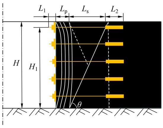
Figure 5.
Sketch of bolt length calculation in roadway side.
The primary functions of the rib bolts are to reinforce the coal mass in the shallow and medium-deep zones, thereby enhancing the integrity of the fractured surrounding rock, and to control the deep coal mass by restraining the shear slip of the “wedge-shaped” plastic zone. Therefore, the rib bolts must extend beyond the potential shear slip surface and possess a sufficient anchorage length L2. Consequently, the bolt length L should satisfy the following equation:
where L1 is the exposed bolt length (m); L2 is the internal anchorage length (m); and Lp is the depth of the tensile (splitting) failure zone (m), which can be determined through field measurements or the RFPA numerical simulation method [19].
where H1 is the height of the supported rib (m). If bolt support is employed for the rib of a coal roadway, the bolt length must be sufficient to penetrate the potential shear slip surface and enhance the shear resistance of the coal mass; only by meeting this requirement can the stability of the rib surrounding rock be effectively controlled.
3.3. Mechanical Analysis of Bending Deformation of the Roof
In this paper, the influence of the top coal thickness (characterized by the thickness-to-span ratio) on roof deformation is considered, while the effect of horizontal stress is neglected. The Timoshenko beam theory is introduced [20,21], as illustrated in Figure 6, where the beam possesses a rectangular cross-section with width b and height h.
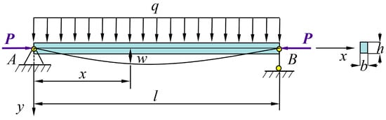
Figure 6.
Axially loaded Timoshenko beam model.
The governing equation for an axially loaded Timoshenko beam [22,23,24] can be expressed as:
where w and θ represent the deflection and rotation of the beam cross-section, respectively. α is the transition coefficient characterizing the direction of the axial force, varying between 0 and 1. α = 0 indicates the axial force is parallel to the neutral axis of the undeformed beam. α = 1 indicates the axial force remains perpendicular to the deformed beam cross-section.
By simultaneously solving and eliminating parameters, the following equation is obtained:
where
where κ is the shear correction factor.
Assuming a concentrated load of magnitude q is applied to the beam at x0, the governing equation becomes:
where δ(x) is the Dirac delta function. The solution to the above equation corresponds to the mathematical Green’s function solution for this boundary value problem.
Taking the Laplace transform of Equation (11) with respect to the coordinate x yields:
where s is the Laplace transform parameter, and w(0), w’(0), w’’(0), w’’’(0) are undetermined constants.
Applying the inverse Laplace transform to Equation (14) yields:
where H(x) is the Heaviside step function. The functions ψi(x) are defined as follows:
The general solution of Equation (13) can be obtained via the Laplace transform method. The undetermined constants in Equation (15) can be determined by applying the boundary conditions. Before calculating these constants, the expressions for the rotation θ, bending moment M, and shear force V are defined as:
From Equation (15), we obtain:
For a simply supported beam, the boundary conditions must satisfy w(0) = 0, M(0) = 0, w(l) = 0, and M(l) = 0. Substituting these into Equation (16) gives:
Substituting Equation (16) into the above equations yields:
Substituting these constants back into Equation (15) yields the explicit expression for the deflection. Combining the Green’s function solution from Equation (13), the deflection corresponding to a distributed load q(x) acting on the beam can be obtained through the principle of superposition:
where χ2(u) is the amplification factor.
Under the simply supported boundary condition, assuming a uniformly distributed load q = 0 and α = 0, the critical buckling load [25] for roof failure is derived as:
Equation (22) reveals that the maximum deformation of the roof is the product of three factors: the base term remains the deflection solution of the simply supported beam model; the middle term represents the additional deflection induced by the shear effect, which, given constant strength parameters of the roof, is primarily determined by its thickness-to-span ratio. A larger thickness-to-span ratio leads to greater roof deformation. The final term is the amplification factor, which acts as a multiplier for the roof deformation caused by horizontal stress. When the strength parameters of the roadway roof are fixed, this factor is governed solely by the magnitude of the horizontal stress.
4. Coordinated Support Technology of Sidewall and Roof for Floor-Following Drift in Thick Coal Seam
4.1. Coordinated Support Design of Sidewall and Roof
The surrounding rock of a coal roadway refers to the rock mass affected by the excavation-induced disturbance. For the roadway itself, this includes the roof, floor, and both ribs. Coal roadways are distinctive as both ribs, or possibly both the roof and floor, may consist entirely of coal. Traditional support theories for coal roadways have often overemphasized the importance of roof control while neglecting the significance of rib maintenance. Furthermore, it is equally inadvisable to place excessive emphasis solely on the control of the roadway ribs.
The stability of the surrounding rock in coal roadways is primarily determined by three factors: the properties (strength) of the surrounding rock, the in situ stress, and the support system. Support is essentially employed to compensate for the mismatch between the strength of the surrounding rock and the prevailing stress conditions. Consequently, the criterion for assessing roadway stability is the relationship between the strength of the surrounding rock and the in situ stress. To achieve synergistic support between the roadway ribs and roof, the Strength-to-Stress Ratio (S) is introduced as a key indicator to evaluate the stability of both the roof and the ribs. Compensatory support is then designed and applied based on whether the stability of the roof or ribs is assessed as strong or weak. This approach ensures that roadway maintenance is safe, reliable, and economically rational, ultimately achieving the goal of synergistic support between the roadway roof and ribs.
Herein, the strength–stress ratio, denoted as S [26,27,28], represents
where K represents the ratio of the long-term strength of soft rock to its peak strength; for hard rock, K is taken as 1; Kv denotes the rock mass integrity coefficient, with Kv = (νm/νc)2; vm stands for the longitudinal wave velocity of rock mass, in m/s; vc stands for the longitudinal wave velocity of rock, in m/s; σcw represents the saturated uniaxial compressive strength of rock, in MPa; σ1 represents the maximum principal stress of the surrounding rock, in MPa.
To quantify this assessment and guide the optimization, stability thresholds for the Strength-to-Stress Ratio S are proposed based on field experience and theoretical back-analysis in similar conditions [29,30]:
① S ≥ 1.5: Stable. The surrounding rock strength is sufficient to withstand the in situ stress with minimal time-dependent deformation.
② 1.0 ≤ S < 1.5: Marginally stable/Critical. The surrounding rock may experience significant time-dependent deformation or local failure; active support is required to maintain stability.
③ S < 1.0: Unstable. The surrounding rock strength is inadequate, likely leading to rapid, large deformation or failure without substantial reinforcement.
Based on field measurements and theoretical analysis, the comprehensive failure depth of the rib, calculated from Equation (6), is Lz = Lp + Ls = 0.15 + 2.16 = 2.31 m. The upper section of the rib exposes soft coal, while the integrity of the top coal remains relatively good. Analysis of the in situ stress and surrounding rock strength parameters reveals that the Strength-to-Stress Ratio (S) at the rib is as low as 0.7. This low value indicates an unstable condition, necessitating an enhanced rib support design. Concurrently, the synergistic support between bolts and cable bolts was optimized. Integrating the aforementioned theoretical analysis with the observed field deformation and failure characteristics, the original support scheme for the 2201 haulage gateway was optimized. Key modifications across the three proposed roof support schemes include optimizing the cable bolt spacing from the original 1600 × 1800 mm to 2400 × 1800 mm, and altering the spatial relationship between the cable bolts and the bolts. Specifically, the cable bolts were relocated from their original position between two rows of bolts to a new alignment within the same column as certain bolts, leading to the omission of the bolts originally occupying those positions. Furthermore, the rib support design was also optimized. The four support schemes (including the original and the three optimized variants) are detailed as follows:
Original Support Scheme for Roadway Ribs: Each rib was supported by five Φ20 × 2200 mm high-strength left-hand threaded steel bolts, spaced at 800 × 900 mm. The top and bottom bolts of each rib were installed 200 mm from the roof and 700 mm from the floor, respectively, and were inclined at a 15° angle upwards and downwards from the horizontal direction.
Optimized Support Scheme 1 for Roadway Ribs: The rib bolts were upgraded from Φ20 × 2200 mm to the same specification as the roof bolts, namely Φ22 × 2500 mm high-strength left-hand threaded steel bolts. Furthermore, the bolt pattern was locally densified in the upper soft coal section, with the spacing reduced from 800 × 900 mm to 533 × 900 mm. Bolts in the same vertical row were connected using a steel strap.
Optimized Support Scheme 2 for Roadway Ribs: Short cable bolts were employed to locally reinforce the soft coal section in the upper part of the rib, replacing the middle bolt originally installed in that soft coal zone.
Optimized Support Scheme 3 for Roadway Ribs: Two short cable bolts were used to locally reinforce the soft coal section in the upper part of the rib, replacing the top and bottom two bolts originally installed in that soft coal zone. The support design cross-sections for the original scheme and the three optimized schemes are illustrated in Figure 7.
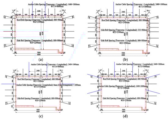
Figure 7.
Roadway support optimized design. (a) Original Support Scheme; (b) Optimized Scheme 1; (c) Optimized Scheme 2; (d) Optimized Scheme 3.
The calculation results of the strength–stress ratio S for the key parts of the original support scheme and the three optimized schemes (roof and upper weak coal side) are summarized in Table 1.

Table 1.
Strength-to-Stress Ratio (S) assessment for different support schemes.
According to the surrounding rock stability classification standard (S ≥ 1.5 indicates stable, 1.0 ≤ S < 1.5 indicates marginally stable, and S < 1.0 indicates unstable), the field observations closely align with the calculated results: the roof (S ≈ 1.8) remains consistently stable, exhibiting minimal deformation and good integrity, while the coal rib in the original support section (S = 0.7) is in an unstable state, showing severe rib spalling, bulging, and unstable deformation. After optimized support, all three schemes improve the S-value of the coal rib, but to varying degrees. Among them, Optimized Scheme 1 significantly increases the rib’s S-value to 1.33, firmly placing it in the middle of the “marginally stable” range; Schemes 2 and 3 only raise the S-value slightly above the stability threshold (approximately 1.0–1.17), resulting in limited improvement. Quantitative analysis reveals that the essence of “synergistic support” lies in identifying and effectively reinforcing the weakest component (i.e., the coal rib). By comprehensively strengthening the coal rib, Optimized Scheme 1 achieves a balanced and effective synergy, bringing the inherently stable roof and the adequately reinforced rib into a compatible state of stability. This conclusion has been further validated by subsequent numerical simulations and physical tests.
4.2. Numerical Simulation Analysis
For a comparative analysis of the control effects of different support schemes on the surrounding rock, a numerical model was established based on the geological and mining conditions of the 2201 transportation roadway. The model dimensions are length × width × height = 50 m × 15 m × 30 m. The simulation was conducted using FLAC3D software (v. 9.0) based on the explicit finite difference method. In the model, each rock and soil layer is treated as a continuous, homogeneous, and isotropic elastoplastic medium, whose deformation and failure obey the Mohr–Coulomb strength criterion. The physical and mechanical parameters of each coal and rock layer are listed in Table 2. The model employs a structured hexahedral mesh overall, with local refinement in the surrounding rock area of the roadway to ensure sufficient accuracy in stress and displacement solutions while maintaining computational efficiency. The boundary conditions were determined according to in situ stress measurement results and engineering practice: fixed constraints were applied at the bottom of the model (in the Z-direction), with displacements restricted in all directions. To simulate the in situ stress field, boundary loads were applied based on the average overburden depth of 722 m at the study site. A vertical compressive stress (σv) of 18 MPa, corresponding to the average overburden weight, was applied to the model’s top surface. In accordance with the geostatic stress ratio (λ = σh/σv) of 1.1 determined from field measurements and adopted in the physical model tests (see Section 4.3 and Table 3), the horizontal stresses in both the X and Y directions were set to 19.8 MPa (i.e., σh = λ × σv = 1.1 × 18 MPa). This configuration represents a slightly anisotropic stress state typical for the mining district, allowing the model to focus on the fundamental interaction between the support system and the surrounding rock under representative regional stresses. Normal displacement constraints were applied to the four sides of the model (in the X and Y directions) to simulate the constraining effect of the semi-infinite far-field rock mass. The support structures (bolts, anchor cables, steel straps/beam ladder beams, and wire mesh) were simulated using the built-in “cable” and “beam” structural elements in FLAC3D. Appropriate grout bonding and frictional parameters were set to achieve full coupling between the support components and the surrounding rock, thereby fully accounting for the surrounding rock—support interaction (SSI). The simulation process strictly followed the construction sequence of “first equilibrating the initial in situ stress field → excavating the roadway → immediately installing the support → continuing the calculation until equilibrium,” in order to realistically reflect the timeliness of excavation disturbance and support.
Table 2.
Physico-mechanical parameters of coal and rock strata.
Table 3.
Comparison of deformation of monitoring points.
Figure 8 shows the vertical and horizontal displacement distributions of the surrounding rock for the original scheme and optimized schemes 1, 2, and 3, respectively. The blue and red areas indicate the maximum displacement zones at the roof-floor and the two ribs. The simulation results demonstrate that after optimizing the original scheme, the extent of both blue and red areas is reduced to varying degrees. This indicates that adjusting the roof support and enhancing the rib support positively contributes to controlling roadway surrounding rock deformation. The vertical displacement of the roadway roof and the horizontal displacement of the ribs are significantly influenced by the support intensity in the soft coal sections of the ribs, while the floor displacement is less affected. As the support for the soft coal in the ribs is strengthened, the displacement in the deep surrounding rock of the roadway gradually decreases, with this effect being more pronounced in the shallow parts. Regarding the roof, the adjustment of the original support scheme resulted in a slight reduction in the maximum surface displacement of the roof, but this reduction is not significant. The floor displacement remains essentially consistent across all schemes, showing no notable change.
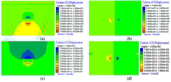
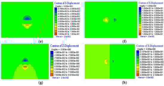
Figure 8.
Displacement contour maps of different support schemes. (a) Original scheme vertical displacement contour map; (b) Original scheme horizontal displacement contour map; (c) Optimized scheme 1 vertical displacement contour map; (d) Optimized scheme 1 horizontal displacement contour map; (e) Optimized scheme 2 vertical displacement contour map; (f) Optimized scheme 2 horizontal displacement contour map; (g) Optimized scheme 3 vertical displacement contour map; (h) Optimized scheme 3 horizontal displacement contour map.
To quantitatively compare the original scheme and the three optimized schemes, displacement values at identical monitoring points from the numerical simulations of the different support schemes were extracted, as detailed in Table 3. Roof deformation is represented by the displacement at the center point, while rib convergence is represented by the maximum horizontal displacement point. A comparison of the support effectiveness of the different schemes is thus conducted.
As can be seen from Table 2, compared to the original scheme, Scheme 1 reduces roof subsidence by 51.985 mm, a decrease of approximately 39.71%. The reduction in rib convergence is the most significant, decreasing from 480.21 mm to 157.73 mm, a reduction of about 67.15%. This indicates that after comprehensively strengthening the overall rib support and locally reinforcing the soft coal, the rib convergence is markedly improved, with a reduction exceeding 50%. Adjusting the roof support by installing bolts and cable bolts in the same row connected by steel straps also led to a significant reduction in roof subsidence. This improvement can be attributed to two main factors: firstly, the coordinated support achieved by installing bolts and cable bolts in the same row indeed enhances the support effectiveness; secondly, it demonstrates that the synergistic support of the roof and ribs can improve roadway surrounding rock deformation. After the rib support is significantly enhanced, the roof subsidence can also be effectively suppressed. This finding indirectly confirms the previously identified insufficiency in the rib support of the original scheme and validates the accuracy of the earlier stability assessment method based on the relative strength of the roof and ribs.
Figure 9 displays the distribution curves of deformation at the left rib and roof subsidence for the four different support schemes. As shown in Figure 9a, the maximum rib deformation occurs in the soft coal section. Implementing varying degrees of enhanced support in the rib resulted in reduced deformation across all three optimized schemes. Particularly in Scheme 1, where overall rib support was strengthened combined with local densification in the soft coal zone, the development of rib deformation was significantly suppressed. Furthermore, Figure 9b indicates that the maximum roof subsidence occurs at the mid-span. After the unified adjustment of roof support in the optimized schemes, the roof subsidence demonstrated varying degrees of reduction. This improvement is primarily attributed to the different degrees of rib reinforcement. Scheme 1, with the highest degree of rib reinforcement, exhibits the smallest deformation, the best stability, and consequently, the most significant reduction in roof subsidence.
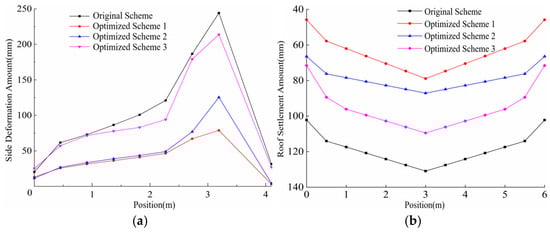
Figure 9.
Roadway deformation amounts at different positions. (a) Left side deformation amount; (b) Roof settlement amount.
A comprehensive comparative analysis reveals that the maximum deformation occurs in the soft coal sections of the roadway ribs. By implementing varying degrees of reinforcement to the rib support, all three optimized schemes resulted in reduced rib deformation. Notably, Scheme 1, which combined overall rib reinforcement with localized support densification in the soft coal zones, significantly inhibited the development of rib deformation. Furthermore, the maximum roof subsidence was observed at the mid-span. After implementing unified adjustments to the roof support in the optimized schemes, roof subsidence decreased to varying degrees. This improvement is primarily attributed to the differing levels of rib reinforcement. Specifically, Scheme 1, featuring the most substantial rib reinforcement, exhibited the smallest deformation, the highest stability, and consequently, the most significant reduction in roof subsidence.
4.3. Model Test Research
Based on the engineering geological conditions of the 2201 haulage gateway and the dimensions of the physical modeling test platform, the geometric similarity constant CL for the model was designed as 25, and the unit weight similarity constant Cγ as 1.32. Consequently, the stress and strength similarity constant was determined as Cσ = CL × Cγ = 32.89. The model dimensions were 1400 mm × 1400 mm × 200 mm, with the roadway scaled to 240 mm × 164 mm. Stress monitoring during the model tests was conducted using pre-embedded earth pressure cells, with data acquisition performed via a DH3816 strain instrument (Donghua Testing Technology Co., Ltd., Jingjiang, China). The design of the model test and the layout of monitoring points are illustrated in Figure 10. Two sets of model tests were designed to compare the deformation and failure characteristics of the surrounding rock between the original support scheme and Optimized Scheme 1, thereby validating the feasibility of the optimized scheme.
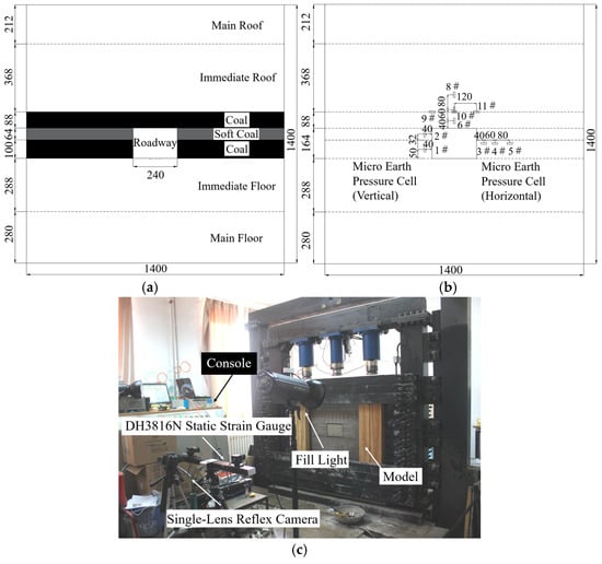
Figure 10.
Physical model experimental system. (a) Schematic diagram of the model layout and dimensions; (b) Layout plan of the embedded earth pressure cells; (c) Photograph of the test platform.
The model test employed a step-by-step loading method, with the loading path detailed in Table 4. To compare the deformation and failure characteristics of the roadway surrounding rock under the original support scheme and the optimized scheme, and considering the challenges associated with physically installing support elements within the limited space of the roadway model—which could easily cause undesired disturbance and damage to the surrounding rock—the tests were conducted using the sequence of “excavation first, followed by support installation, and then applying the load.”
Table 4.
Loading path.
Figure 11 illustrates the surrounding rock configurations of the two different support schemes under each loading step, as well as the curves depicting the variation in vertical stress at the roadway ribs and the corresponding deformation data for both the original and optimized support schemes throughout the step-wise loading process.


Figure 11.
Roadway surrounding rock morphology and stress-deformation data of different schemes. (a) Surrounding rock deformation and failure situation under different loading conditions before and after optimization; (b) Roadway surrounding rock stress before and after optimization; (c) Roadway surrounding rock deformation before and after optimization.
As shown in Figure 11, within the load range of 0–39.50 kN, the left rib floor corner of the roadway with the original support was subjected to concentrated stress, leading to localized fracture damage and the emergence of multiple cracks. In contrast, the roadway with the optimized scheme exhibited only minor bending deformation in the roof and the lower sections of both ribs, with no obvious fracture damage observed, indicating good integrity of the surrounding rock. When the load was increased to 60.78 kN, the floor corners of both ribs in the original support roadway experienced large-scale fracture damage, which propagated along the bedding planes into the deeper surrounding rock on both sides. The coal mass near the floor corners was crushed, while the roof and ribs underwent overall bending and subsidence, with the rib walls tilting into the roadway space, resulting in severe contraction of the cross-section. In the optimized scheme, the bending deformation of the ribs and roof increased only slightly, accompanied by minor floor heave, while the integrity of the surrounding rock remained good. As the load was further increased to 103.34 kN, the fracture damage at the floor corners of the original support roadway continued to intensify, with both the extent and depth of the crushing zone expanding and the volume of failed material increasing. The floor corners gradually assumed an approximately curved shape, while the ribs and roof experienced ongoing bending and subsidence. The coal mass above the bedding planes exhibited progressively deeper and more severe fracturing along the bedding. In the optimized scheme, the rib convergence and roof subsidence increased only marginally, and the surrounding rock underwent continuous, coordinated deformation without significant failure. When the load reached 145.90 kN, the floor corners of the original support roadway were further crushed and damaged, accompanied by continuous settlement of the ribs and roof, rapid contraction of the cross-section, and a highly irregular roadway profile, with varying degrees of failure in both the ribs and roof. In the optimized scheme, the increase in roof subsidence remained small, with slight opening of oblique cracks at the two roof corners that propagated toward the center and nearly intersected. No significant changes were observed in the ribs or other sections, and the surrounding rock maintained good integrity.
From the perspectives of failure characteristics, stress field, and displacement field, a comparative analysis of the deformation, failure behavior, and support effectiveness between the original and optimized support schemes was conducted. The roof-and-rib synergistic support scheme effectively controls surrounding rock deformation. Multiple comparative tests showed that, compared to the original scheme, the optimized scheme (Scheme 1) consistently reduced the maximum horizontal displacement of the rib by 65–68% and the maximum vertical displacement of the roof by 72–76% across different loading stages. In a representative test under the equivalent field stress condition (corresponding to a depth of ~720 m), the reductions were approximately 67% and 74%, respectively. This indicates a significant and robust enhancement in surrounding rock control. The roof-and-rib synergistic support scheme not only reinforces weak zones and improves the stability of the fragile surrounding rock, but also mobilizes the self-supporting capacity of the competent rock sections, fully utilizing their inherent stability. This approach couples effectively with the combined support provided by bolts and cable bolts, thereby improving the overall stability and integrity of both the ribs and the roof in thick coal seam floor roadways. Furthermore, this synergistic support improves the stress state within the surrounding rock, alleviates stress concentration in the ribs, and promotes relatively uniform load-bearing in the rib surrounding rock. Concurrently, the radial stress in the roof increases, enhancing its load-bearing capacity. These two aspects interact and mutually reinforce each other, leading to a more rational stress distribution within the surrounding rock and helping to mitigate detrimental stress concentrations.
5. Engineering Application
Building upon the previous numerical simulation analysis and similar simulation testing of the optimized support schemes, the optimal scheme was identified and subsequently implemented in the field at the 2201 haulage gateway. During this field application, monitoring was conducted to track roadway surface convergence, roof separation, and the axial loads of bolts and cable bolts. This monitoring aims to validate the rationality of the proposed roof-and-rib synergistic support theory and technology for deep thick coal seam floor roadways.
5.1. Monitoring Station Layout
To evaluate the control effect of the roof-and-rib synergistic support on the stability of the surrounding rock in thick coal seam floor roadways, systematic monitoring was conducted during the excavation of both the original support section and the test section. Monitoring equipment, including the EPK-10 mining-type convergence gauge, the WBY-10 roof separation instrument, and the MZC-200 bolt (cable) force sensor (Shandong China Coal Industry and Mining Supplies Group Co., Ltd., Jining, China), was employed to track roadway surface displacement, roof separation, and the axial forces in the bolts and cable bolts, respectively.
Displacement monitoring stations 1# and 2# are situated within the original support scheme section, while stations 3#, 4#, and 5# are located in the test section employing the optimized scheme. The specific layout of these monitoring points is illustrated in Figure 12.
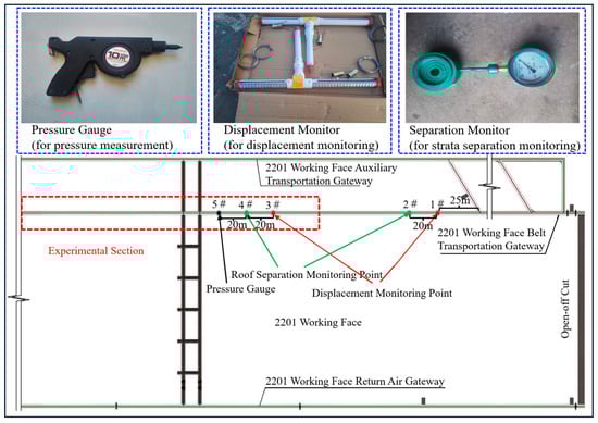
Figure 12.
Layout of measuring points.
5.2. Test Results Analysis
Based on the time-series data of roadway surface displacement, roof separation, and the axial forces in the bolts and cable bolts, a comparative analysis of the monitoring data from the test section and the original support section was conducted to verify the feasibility of the proposed support scheme. The relationships between surrounding rock deformation, bolt load, and time for monitoring stations 1# and 3# are plotted as shown in Figure 13.
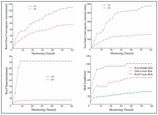
Figure 13.
Relationship between surrounding rock deformation, bolt load and time for original scheme and optimized support scheme.
As shown in Figure 13, the roof-to-floor convergence rate increased rapidly during the initial stage. Specifically, at Station 1# (original support scheme), the relative convergence rate reached 4.5 mm/d, while at Station 3# (optimized scheme), it was approximately 2.5 mm/d. After about 20 days, the convergence at Station 1# continued to increase until the 54th day, whereas at Station 3#, it gradually stabilized, followed by a slow increase and then a further deceleration. When the roadway stabilized, the surrounding rock deformation rate was ≤0.15 mm/d. The final roof-to-floor convergence was about 130 mm under the original support scheme, compared to approximately 78 mm under the optimized scheme—a reduction of 40.0%, demonstrating a significant improvement in roof control effectiveness.
The rib convergence rate increased rapidly during the initial stage. Specifically, at Station 1# (original support scheme), the convergence rate reached 18 mm/d, while at Station 3# (optimized scheme), it was approximately 5 mm/d. After about 20 days, the convergence at Station 1# continued to increase until the 54th day, whereas at Station 3#, it gradually stabilized, followed by a slow increase and then a further deceleration. As the distance from the excavation face increased, the surrounding rock deformation rate decreased, and the roadway deformation tended to stabilize. The excavation disturbance period lasted about 54 days for the original support scheme, compared to a shorter period of approximately 42 days for the optimized scheme. Upon stabilization, the surrounding rock deformation rate was ≤0.15 mm/d. The final rib convergence was about 480 mm under the original support scheme, compared to approximately 165 mm under the optimized scheme—a reduction of 65.6%, indicating a significant improvement in rib control effectiveness.
Roof separation occurred predominantly within the first 12 days. At monitoring station 2# (original support scheme), the roof separation developed rapidly after initiation, reaching a separation rate of 7 mm/d, and subsequently remained largely constant. The evolution pattern of roof separation at station 4# was fundamentally similar to that at station 2#; however, both the separation rate and total magnitude were significantly lower. The maximum initial separation rate was only about 1.5 mm/d, and the total separation stabilized at approximately 7 mm. These results demonstrate the optimized scheme’s effectiveness in controlling roof separation in the thick coal seam floor roadway. It successfully ensures coordinated deformation between the top coal and the overlying strata, thereby maintaining roof safety. The in situ effect within the roadway is shown in Figure 14.
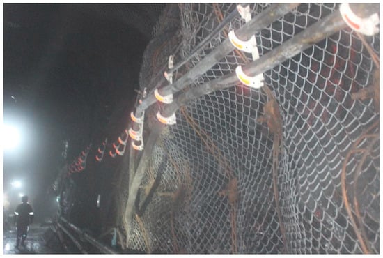
Figure 14.
In situ view of the supported roadway.
The bolt at the mid-span of the roof carries the highest load, followed by the bolts at the rib-floor corners, while the bolts at the roof-wall corners bear the smallest load. This distribution pattern corresponds well with the specific ground conditions and the observed deformation and failure characteristics of the haulage gateway. The axial force in the bolts generally exhibits an increasing trend over time, which can broadly be divided into three stages: ① Rapid Growth Stage: Lasting approximately 10 days after excavation, during which the axial force increases rapidly. ② Fluctuation Stage: Occurring roughly between 10 and 40 days post-excavation, characterized by frequent fluctuations in the axial force. ③ Stabilization Stage: Beginning around 50 days after excavation, where the axial force essentially stabilizes. The timing of this stabilization corresponds well with the stabilization of the surrounding rock surface displacements. The maximum load sustained by the bolts is approximately 100 kN, which is significantly less than the ultimate load capacity of the high-strength bolts.
In summary, following the support optimization in the 2201 haulage gateway, the roof-to-floor convergence was measured at 75 mm and the rib convergence at 160 mm, both of which fall within the allowable deformation limits. Roof separation was well-controlled, and both the bolts and cable bolts retain significant residual load-bearing capacity. The overall control of the surrounding rock is therefore deemed satisfactory. The significant reduction in deformation and the maintenance of the roadway within allowable limits demonstrate a marked improvement in the stability and safety of the supported roadway under high-stress conditions. The data analysis in this study focused on the critical excavation disturbance phase (approximately the first 60 days). To address long-term stability, monitoring was continued until the roadway was within 50 m of the advancing 2201 longwall face, covering a total period of over 180 days. During this extended monitoring period leading up to stope operations, the deformation rates of the optimized section remained consistently below 0.1 mm/day, and no acceleration in convergence or degradation of bolt/cable loads was observed. This sustained stability aligns with the industry empirical criterion that a roadway can be considered stable for long-term service when its deformation rate decays and remains below 0.2 mm/day over a significant period [31]. The absence of new deformation acceleration during the face approach phase further confirms that the synergistic support system effectively provided sufficient resistance to the anticipated abutment stress, maintaining the roadway in a safe and serviceable state until its planned service life ended.
6. Discussion
(1) The calculation of the comprehensive rib failure depth (Lz = Lp + Ls) assumes sequential development of the tensile/splitting (“H-shaped”) and shear (“Y-shaped”) zones with minimal overlap. This assumption is consistent with field and numerical evidence from the studied roadway, where shear failure initiated beyond the fractured splitting zone. The summation provides a conservative design estimate, prioritizing safety by ensuring bolt anchorage beyond the critical shear surface. It is acknowledged that under different conditions (e.g., higher horizontal stress), zone overlap may occur, potentially leading to an overestimation. A more generalized model, introducing a reduction factor α (0 < α ≤ 1) such that Lz = Lp + α·Ls, could account for this interaction. Calibrating α through future analysis of field data across varied conditions represents a promising direction for refining support design economically while upholding safety.
(2) On the numerical solution of governing equations: The governing equations for roof deformation (e.g., Equations (18) and (19)) are solved here using standard analytical and numerical methods, which are adequate for the present analysis. For future extensions involving more complex constitutive models (e.g., viscoplasticity or anisotropic damage) or dynamic conditions, the resulting matrix systems may become more challenging to solve efficiently. In such cases, the adoption of advanced iterative solvers, such as Hermitian and skew-Hermitian splitting (HSS) methods, could be highly beneficial [32,33]. Exploring these robust numerical schemes for advanced versions of the presented model is a valuable direction for future computational research, with the potential to enable faster and more stable simulations for design optimization.
(3) Considerations on dynamic data processing: The data analysis in this study primarily concerns the final, stabilized deformation state and key parameters (e.g., comprehensive failure depth, final convergences). For potential future applications involving long-term, real-time monitoring and sequential data assimilation (e.g., for predictive maintenance or early warning systems), the dynamic and sequential nature of the incoming data would require specialized processing. Implementing dynamic filtering, state-updating algorithms (e.g., Kalman filters [34]), and automated normalization procedures [35] for large-scale, heterogeneous monitoring data would be essential to ensure robust trend analysis and model updating. Developing and integrating such a dynamic data processing framework constitutes an important direction for advancing the presented methodology towards intelligent, real-time ground control.
(4) Comparative analysis and evidential basis: The proposed “H-shaped and Y-shaped” failure mechanism and synergistic support theory were derived from and are consistent with field observations, physical simulations, and numerical analyses specific to the Yingpanhao case. Compared to traditional approaches that often treat roof and rib support in isolation or rely on empirical rules, the present method offers a more integrated, mechanics-based design framework. Its superior performance is evidenced by the significant reductions in deformation (rib convergence down by ~66%, roof convergence by ~40%) and maintenance costs (32%) achieved in the field application, as detailed in Section 4 and Section 5.
(5) Limitations and sources of uncertainty: The numerical model in this study, based on continuum mechanics and the Mohr–Coulomb criterion, provides a simplified yet effective representation of the primary failure mechanisms. This simplification, while necessary for analytical tractability, introduces limitations and uncertainties into the predictions:
① Modeling Idealisations: Key assumptions include treating the coal mass as homogeneous and isotropic for rib analysis, and using an equivalent continuous medium in simulations. These assumptions facilitate the capture of primary mechanisms but may not fully represent in situ heterogeneity, discrete fracture networks, or more complex rock mass behaviors.
② Parameter Uncertainty: The inherent spatial variability of rock mass properties (e.g., cohesion c, friction angle φ, shear zone depth Ls) leads to significant parameter uncertainty. This is compounded by the specific geological origin of our extensive field monitoring data, which limits the direct extrapolation of absolute deformation values to other mining settings and affects the precise calibration of model parameters.
③ Numerical Discretization Error: This form of uncertainty was controlled through a standard mesh sensitivity analysis [36], where refinement continued until key outputs (e.g., peak displacement) varied by less than 5% between successive iterations. Thus, numerical error is considered negligible relative to the physical (parameter) uncertainty.
The current design philosophy of this paper does not address these uncertainties by pursuing unattainable parameter precision, but rather through a capacity design approach. The proposed collaborative support system is intentionally designed to be robust and redundant, thereby providing a safety margin to ensure the system remains stable even under adverse parameter variations or the presence of unmodeled weak regions.
(6) Future directions: Towards high-fidelity and risk-informed modeling. To advance beyond the current simplifying assumptions and explicitly manage uncertainty, future research should integrate two synergistic, forward-looking directions:
① Development of High-Resolution Geo-Models: Moving from simplified homogeneous assumptions to high-resolution 3D geo-models that explicitly capture lithological heterogeneity and spatial distribution is crucial. This would reduce epistemic uncertainty by providing a more realistic representation of the subsurface, forming a superior basis for advanced numerical simulations.
② Implementation of Uncertainty Quantification (UQ) Frameworks: To complement high-fidelity models, probabilistic UQ frameworks—such as hybrid ensemble-based methods or automated deep learning techniques [37]—should be implemented. These frameworks can efficiently propagate parameter uncertainties, assimilate real-time monitoring data, and provide probabilistic forecasts. This transforms the design process from deterministic to risk-informed.
Pursuing these integrated directions in high-fidelity modeling and intelligent UQ will significantly enhance the robustness, generalizability, and predictive intelligence of design systems for complex mining geomechanics problems.
7. Conclusions
The failure mechanism and support technology for deep thick coal seam floor roadways were investigated in this study, taking the 2201 haulage gateway as a case study. The main conclusions are as follows:
(1) The rib failure exhibits a progressive mechanism: tensile/splitting failure forms an “H-shaped” zone in shallow to medium depths, while deeper failure is characterized by an incomplete conjugate shear (“Y-shaped”) slip.
(2) A comprehensive rib failure depth (Lz), defined as the sum of tensile (Lp) and shear (Ls) failure depths, is proposed. This forms the basis for a new bolt length design formula to ensure anchorage beyond the potential shear slip surface.
(3) The roof deformation is governed by a superposition of bending deflection, shear effect (related to thickness-to-span ratio), and an amplification factor induced by horizontal stress.
(4) Physical model tests confirm that the proposed rib-roof synergistic support scheme effectively controls deformation, consistently reducing rib displacement by 65–68% and roof displacement by 72–76% compared to the original scheme.
(5) Field application validated the technology, achieving controlled roof-to-floor convergence of 78 mm and rib convergence of 165 mm. These values represent reductions of approximately 40.0% and 65.6%, respectively, and are well within the allowable deformation limits for safe operation, demonstrating a significant improvement in roadway stability under high-stress conditions.
Author Contributions
Conceptualization, Y.P. and H.J.; methodology, Y.P.; validation, Y.P., H.J. and Z.P.; formal analysis, Z.P. and Q.F.; resources, Q.F. and C.L.; writing—original draft preparation, Y.P., Z.P. and J.Z.; writing—review and editing, C.L.; supervision, Q.F. and J.Z.; project administration, H.J.; funding acquisition, Q.F. All authors have read and agreed to the published version of the manuscript.
Funding
This work is supported by the National Natural Science Foundation of China (42502259), and the State Key Laboratory for Tunnel Engineering (TESKL202418), which are gratefully acknowledged.
Institutional Review Board Statement
Not applicable.
Informed Consent Statement
Not applicable.
Data Availability Statement
The data that support the findings of this study are available within the article.
Acknowledgments
The authors highly acknowledge the National Natural Science Foundation of China and the State Key Laboratory for Tunnel Engineering for financial support.
Conflicts of Interest
Author Yanghao Peng was employed by the company Huadian Coal Industry Group Co., Ltd. The remaining authors declare that the research was conducted in the absence of any commercial or financial relationships that could be construed as potential conflicts of interest.
References
- Fu, Q.; Yang, J.; Gao, Y.B.; Li, C.J.; Song, H.X.; Liu, Y.X.; Wu, X. Combined blasting for protection of gob-side roadway with thick and hard roof. J. Rock Mech. Geotech. Eng. 2024, 16, 3165–3180. [Google Scholar] [CrossRef]
- Fu, Q.; Yang, J.; Gao, Y.B.; Li, C.J.; Chang, X.; Wu, X. Mechanism and surrounding rock control of gob-side entry formation passing through normal fault: A case study. Environ. Earth Sci. 2023, 82, 603. [Google Scholar] [CrossRef]
- Fan, W.; Han, L. Overburden Behavior and Coal Wall Spalling Characteristics Under Large-Mining-Height Conditions. Appl. Sci. 2025, 15, 12303. [Google Scholar] [CrossRef]
- Liang, S.; Xu, Y.; Shen, J.; Wang, Q.; Liang, X.; Xu, S.; Luo, C.; Yang, M.; Ma, Y. Load–Deformation Behavior and Risk Zoning of Shallow-Buried Gas Pipelines in High-Intensity Longwall Mining-Induced Subsidence Zones. Appl. Sci. 2025, 15, 10618. [Google Scholar] [CrossRef]
- Wang, H.S.; Liu, Y.; Li, L.; Yue, G.X.; Jia, L. Study on Critical Width of Semi-Coal Rock Roadway of Shallow-Buried Thin Coal Seam Based on Coal Side Self-Stabilization. Sustainability 2024, 16, 5689. [Google Scholar] [CrossRef]
- Zhang, G.C.; Chen, L.J.; Wen, Z.J.; Chen, M.; Tao, G.Z.; Li, Y.; Zuo, H. Squeezing failure behavior of roof-coal masses in a gob-side entry driven under unstable overlying strata. Energy Sci. Eng. 2020, 8, 2443–2456. [Google Scholar] [CrossRef]
- Xiang, Y.Z.; Zeng, Z.K.; Xiang, Y.J.; Abi, E.; Zheng, Y.R.; Yuan, H.C. Tunnel failure mechanism during loading and unloading processes through physical model testing and DEM simulation. Sci. Rep. 2021, 11, 16753. [Google Scholar] [CrossRef]
- Li, Y.L.; Yang, R.S.; Fang, S.Z.; Lin, H.; Lu, S.J.; Zhu, Y.; Wang, M.S. Failure analysis and control measures of deep roadway with composite roof: A case study. Int. J. Coal Sci. Technol. 2022, 9, 2. [Google Scholar] [CrossRef]
- Xue, B.; Shang, Y.; Wang, C.; Zhang, F.T.; Liu, Y.F. Research on bending-slip rib spalling and rib stability of extra-thick hard coal wall. Sci. Rep. 2025, 15, 26796. [Google Scholar] [CrossRef]
- Xue, B.; Wang, C.; Wang, Y.Y.; Zhang, W.S.; Yang, S. An investigation of the coal wall zoning failure patterns resulting from the changes in support parameters of large mining height. Mech. Time-Depend. Mater. 2024, 28, 2599–2618. [Google Scholar] [CrossRef]
- Guo, H.J.; Sun, Z.G.; Ji, M.; Wu, Y.F.; Nian, L.H. An investigation on the impact of unloading rate on coal mechanical properties and energy evolution law. Int. J. Environ. Res. Public Health 2022, 19, 4546. [Google Scholar] [CrossRef]
- Wang, E.Y.; Chen, G.B.; Yang, X.J.; Zhang, G.F.; Guo, W.B. Study on the Failure Mechanism for Coal Roadway Stability in Jointed Rock Mass Due to the Excavation Unloading Effect. Energies 2020, 13, 2515. [Google Scholar] [CrossRef]
- Yao, Z.G.; Fang, Y.; Yu, T.; Pu, S.; Luo, H.; Cui, J.; Wang, J. Dynamic failure mechanism of tunnel under rapid unloading in jointed rockmass: A case study. Eng. Fail. Anal. 2022, 141, 106634. [Google Scholar] [CrossRef]
- Wang, F.T.; Liang, N.N.; Li, G. Damage and failure evolution mechanism for coal pillar dams affected by water immersion in underground reservoirs. Geofluids 2019, 2019, 2985691. [Google Scholar] [CrossRef]
- Dooley, T.P.; Schreurs, G. Analogue modelling of intraplate strike-slip tectonics: A review and new experimental results. Tectonophysics 2012, 574–575, 1–71. [Google Scholar] [CrossRef]
- Bishop, A.W. The use of the Slip Circle in the Stability Analysis of Slopes. Geotechnique 1955, 5, 7–17. [Google Scholar] [CrossRef]
- Zhou, X.M.; Wang, S.; Li, X.L.; Meng, J.J.; Li, Z.; Zhang, L.H.; Pu, D.D.; Wang, L.K. Research on theory and technology of floor heave control in semicoal rock roadway: Taking Longhu coal mine in Qitaihe mining area as an example. Lithosphere 2022, 2022, 3810988. [Google Scholar] [CrossRef]
- Wang, B. The principle of virtual energy for predicting the strength of material structures. Eng. Fract. Mech. 2024, 300, 109997. [Google Scholar] [CrossRef]
- Tang, C.A.; Tang, S.B. Applications of rock failure process analysis (RFPA) method. J. Rock Mech. Geotech. Eng. 2011, 3, 352–372. [Google Scholar] [CrossRef]
- Timoshenko, S.P. On the transverse vibrations of bars of uniform cross-section. Lond. Edinb. Dublin Philos. Mag J. Sci. 1922, 43, 125–131. [Google Scholar] [CrossRef]
- Chockalingam, S.N.; Pandurangan, V.; Nithyadharan, M. Timoshenko beam formulation for in-plane behaviour of tapered monosymmetric I-beams: Analytical solution and exact stiffness matrix. Thin-Walled Struct. 2021, 162, 107604. [Google Scholar] [CrossRef]
- Chen, T.; Su, G.Y.; Shen, Y.S.; Gao, B.; Li, X.Y.; Müller, R. Unified Green's functions of forced vibration of axially loaded Timoshenko beam: Transition parameter. Int. J. Mech. Sci. 2016, 113, 211–220. [Google Scholar] [CrossRef]
- Banerjee, J.R.; Kennedy, D. Response of an axially loaded Timoshenko beam to random loads. J. Sound Vib. 1985, 101, 481–487. [Google Scholar] [CrossRef]
- Li, X.Y.; Wang, X.H.; Chen, Y.Y.; Tan, Y.; Cao, H.J. Bending, buckling and free vibration of an axially loaded timoshenko beam with transition parameter: Direction of axial force. Int. J. Mech. Sci. 2020, 176, 105545. [Google Scholar] [CrossRef]
- Li, T.Z.; Yang, X.L. Limit analysis of failure mechanism of tunnel roof collapse considering variable detaching velocity along yield surface. Int. J. Rock Mech. Min. Sci. 2017, 100, 229–237. [Google Scholar] [CrossRef]
- Hoek, E.; Brown, E.T. Empirical Strength Criterion for Rock Masses. J. Geotech. Eng. Div. 1980, 106, 1013–1035. [Google Scholar] [CrossRef]
- Zhang, H.; Li, Y.M.; Wang, X.J.; Yu, S.D.; Wang, Y. Study on Stability Control Mechanism of Deep Soft Rock Roadway and Active Support Technology of Bolt-Grouting Flexible Bolt. Minerals 2023, 13, 409. [Google Scholar] [CrossRef]
- Li, D.; Chang, J.C.; Huang, K.F.; Du, S.Y.; Dou, L.T.; Li, F.H. Experimental study on combined load-bearing instability of filling body and roadway surrounding rock in original roadway filling without coal pillar excavation. Case Stud. Constr. Mater. 2023, 19, e02514. [Google Scholar] [CrossRef]
- TB 10003-2016; Code for Design of Railway Tunnels. China Railway Publishing House: Beijing, China, 2016.
- Wang, L.T.; He, P.; Ma, Z.H.; Liu, N.; Yang, C.X.; Gao, Y.H. Analytical Method for Tunnel Support Parameter Design Based on Surrounding Rock Failure Mode Identification. Geosciences 2025, 15, 369. [Google Scholar] [CrossRef]
- JTG F60-2009; Technical Specification for Construction of Highway Tunnels. China Communications Press: Beijing, China, 2009.
- Bai, Z.-Z.; Golub, G.H.; Ng, M.K. Hermitian and skew-Hermitian splitting methods for non-Hermitian positive definite linear systems. SIAM J. Matrix Appl. 2003, 24, 603–626. [Google Scholar] [CrossRef]
- Bai, Z.-Z.; Golub, G.H.; Pan, J.-Y. Preconditioned Hermitian and skew-Hermitian splitting methods for non-Hermitian positive semidefinite linear systems. Numer. Math. 2004, 98, 1–32. [Google Scholar] [CrossRef]
- Kalman, R.E. A New Approach to Linear Filtering and Prediction Problems. J. Basic Eng. 1960, 82, 35–45. [Google Scholar] [CrossRef]
- Abbaszadeh Shahri, A.; Shan, C.; Larsson, S.; Johansson, F. Normalizing Large Scale Sensor-Based MWD Data: An Automated Method toward A Unified Database. Sensors 2024, 24, 1209. [Google Scholar] [CrossRef]
- Oberkampf, W.L.; Roy, C.J. Verification and Validation in Scientific Computing; Cambridge University Press: Cambridge, UK, 2010. [Google Scholar]
- Zhang, W.G.; Gu, X.; Hong, L.; Han, L.; Wang, L. Comprehensive review of machine learning in geotechnical reliability analysis: Algorithms, applications and further challenges. Appl. Soft Comput. 2023, 136, 110066. [Google Scholar] [CrossRef]
Disclaimer/Publisher’s Note: The statements, opinions and data contained in all publications are solely those of the individual author(s) and contributor(s) and not of MDPI and/or the editor(s). MDPI and/or the editor(s) disclaim responsibility for any injury to people or property resulting from any ideas, methods, instructions or products referred to in the content. |
© 2026 by the authors. Licensee MDPI, Basel, Switzerland. This article is an open access article distributed under the terms and conditions of the Creative Commons Attribution (CC BY) license.