


Abstract
Continuous roof-cutting gob-side entry-retaining has been increasingly applied in deep coal mines to improve entry stability and reduce rockburst susceptibility. However, the structural response of the overburden and the associated load-transfer mechanisms during continuous extraction of multiple adjacent working faces remain unclear. This study integrates theoretical analysis, numerical simulation, and field microseismic monitoring to investigate the progressive adjustment of overburden structures, stress redistribution, and dynamic response under continuous roof-cutting conditions. The results reveal that continuous roof-cutting drives a staged transformation of the overburden bearing system during successive mining. The overburden structure evolves from an asymmetric fracture–subsidence pattern in the initial working face to a uniform subsidence in the successive working face. This evolution modifies stress-transfer pathways and supports the proposed dual-arch collaborative bearing mechanism, in which loads are redistributed through the compacted gangue and deep coal mass, reducing stress concentration and promoting gradual energy release. Field monitoring recorded 346 microseismic events, with 93.64% occurring ahead of the working face and 52.89% located within the roof strata. The maximum energy of mining-induced microseismic events remained below 1 × 10⁴ J throughout the monitoring period, and no abnormal high-energy events were detected during critical squaring stages. The consistency among analytical interpretation, numerical stress redistribution, and field microseismic response supports the proposed mechanism that continuous roof-cutting regulates overburden movement and promotes distributed energy release, thereby reducing rockburst susceptibility under the investigated mining conditions.
1. Introduction
With the depletion of shallow coal resources, mining activities are increasingly extending to greater depths, where high in situ stress, complex geological structures, and intense mining disturbances elevate the risk of dynamic disasters [1,2]. Among these hazards, rockburst has become a major challenge in eastern China’s coal mining due to its sudden occurrence, high destructive potential, and difficult prediction. Gob-side entry-retaining by roof-cutting has been widely applied as a pillar-free mining technology because it improves coal recovery, reduces entry excavation, and optimizes the stress environment of retained entries [3,4,5]. Previous studies have mainly focused on the overburden structural evolution, surrounding rock stability, and stress redistribution during single-working-face mining, demonstrating that roof-cutting can regulate roof movement and reduce stress concentration.
However, deep rockburst prevention is a systematic and dynamic problem rather than merely a entry control issue [6,7]. During the continuous extraction of adjacent working faces, large-scale overburden structures, mining-induced stress fields, and microseismic responses continuously evolve with face advancement. Despite the growing application of continuous roof-cutting gob-side entry-retaining in deep coal mines, the evolution of overburden structures and stress-transfer mechanisms throughout the entire mining process remain insufficiently understood, limiting further optimization and engineering applications.
In recent years, the N00 mining method has emerged as an advanced continuous roof-cutting technology. By eliminating coal pillars and entry excavation, it provides a new approach for gob-side entry-retaining and strata control. This method establishes a surrounding rock control system characterized by “broken-expansion equilibrium-based pressure relief” and “dynamic–static coupled support.” [8]. Physical model tests and field monitoring have demonstrated that continuous roof-cutting enlarges the caving zone, limits fracture-zone development, promotes gangue compaction through fragmented rock bulking, and reduces overburden fracturing and surface subsidence [9,10,11].
Recent studies have shown that hydraulic fracturing and abrasive jet-assisted roof-cutting can promote directional roof caving [12], reduce periodic weighting intensity [13], alleviate stress concentration [14], and stabilize microseismic energy release [15]. Mechanism analyses further indicate that roof-cutting reconstructs the roof-bearing structure and regulates mining-induced stress and elastic energy distribution, providing an active pressure-relief strategy for rockburst mitigation in deep coal mines [16,17].
Roof-cutting blasting creates an additional free surface in the roof strata [18], forming an asymmetric surrounding rock structure characterized by double cantilever beams [19,20]; it also promotes roof caving and enlarges the caving zone, thereby reducing mining-induced damage to overlying strata and providing a basis for proactive overburden structure regulation through stratified presplitting [21,22]. Moreover, roof-cutting-induced structural modification alters the evolution of mining-induced stress, causing the stress arch and high-stress zones to migrate deeper into the coal mass and caved gangue within the gob [23]. Vertically, mining-induced stress transfers upward from the lower to the upper roof strata, resulting in a stress distribution characterized by shallow stress relief and deep stress concentration [24,25]. With working face advancement after roof-cutting, the stress arch further expand, accompanied by the continuous development of a low-stress zone around the retained entry [26].
Roof-cutting-induced pressure relief has attracted considerable attention in rockburst control. Based on fracture connectivity theory, roof-cutting techniques enhance roof fracturing, promote premature roof breakage, and weaken the cantilever effect, thereby mitigating rockburst occurrence [27,28]. For overburden with multiple key strata, the combination of roof-cutting blasting and optimized support systems has been shown to reduce overburden movement intensity [29]. From an energy perspective, suspended roofs and weak floor strata are major factors contributing to rockburst initiation. Pressure-relief measures, including roof-cutting and coal-seam borehole drilling, can reduce elastic energy accumulation in the coal mass, providing proactive approaches for rockburst mitigation [30,31].
Microseismic monitoring has become an effective tool for investigating overburden structural evolution and evaluating roof-cutting-induced pressure relief. The spatiotemporal evolution of microseismic events has been used to characterize hydraulic fracture propagation, determine roof-cutting effectiveness, and establish criteria for overburden failure and fracture development [32,33]. Field observations have further shown that roof-cutting can transform strata failure from high-energy, low-frequency events into low-energy, high-frequency responses, accompanied by reduced microseismic energy release and improved rockburst mitigation performance [34,35]. Recent advances in intelligent signal recognition have further improved the accuracy and reliability of microseismic-based roof-cutting assessments [36].
In this study, a continuous roof-cutting gob-side entry-retaining panel was selected as the engineering case to investigate overburden structural evolution, stress-transfer mechanisms, and rockburst mitigation during successive working face mining. The novelty lies in extending roof-cutting analysis from an individual working face to the continuous multi-face mining and proposing a stage-dependent overburden evolution framework together with a dual-arch bearing mechanism. Theoretical analysis was conducted to interpret overburden structural evolution, while 3DEC simulation provided quantitative insights into stress redistribution, and field microseismic monitoring was used to evaluate whether the observed seismic response was consistent with the proposed mechanism. The findings provide theoretical insights and engineering guidance for continuous roof-cutting applications in deep coal mines.
2. Engineering Background
2.1. Mine Overview
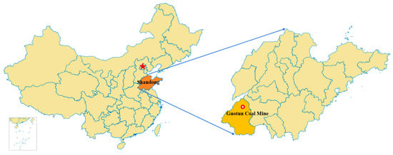
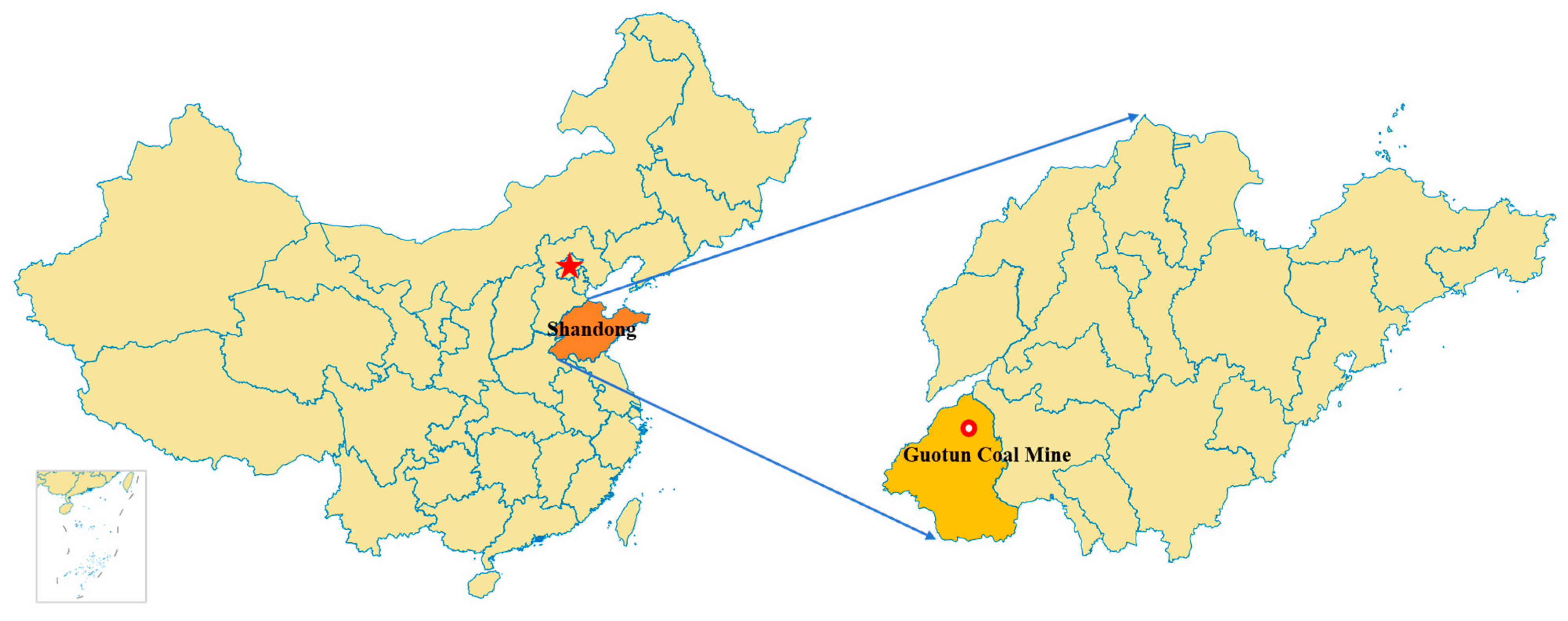
The Guotun Coal Mine is located in Yuncheng County, Heze City, Shandong Province, China (Figure 1), and is one of the major mines in the Juye Coalfield of western Shandong. The mine field is bounded by the Tianqiao Fault and its subsidiary faults to the east, the outcrop of the coal-bearing strata to the west, the Zhaolou Coal Mine field to the south, and the Yuncheng Coal Mine field to the north. The mine has recoverable reserves of 164.607 million tons, with the No. 3 upper and No. 3 lower coal seams as the primary mining seams.
Figure 1.
The location of the experimental area.
The No. 3 lower coal seam is currently mined, with an average thickness of 2.2 m and a burial depth generally exceeding 800 m. Its immediate roof mainly consists of siltstone, with a uniaxial compressive strength (UCS) of 38–110 MPa, while the main roof comprises fine-grained sandstone and medium-grained sandstone, with a UCS of 54–112 MPa, indicating a typical hard-roof condition. In addition, the Guotun Coal Mine was designated as a rockburst-prone mine in 2018, making rockburst mitigation a long-term challenge during mining operations.
2.2. Mining Layout and Support System
The 4308 working face investigated in this study is located southwest of the industrial square of the Guotun Coal Mine. The coal seam strike and dip are 120–160° and 30–70°, respectively, with an inclination of 3–6° (average 4°). The seam is relatively stable with a simple structure in the mining area and has an average thickness of 2.2 m. However, igneous rock intrusion locally reduces the seam thickness in the southern part of the working face.
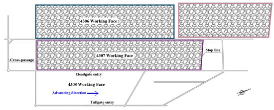
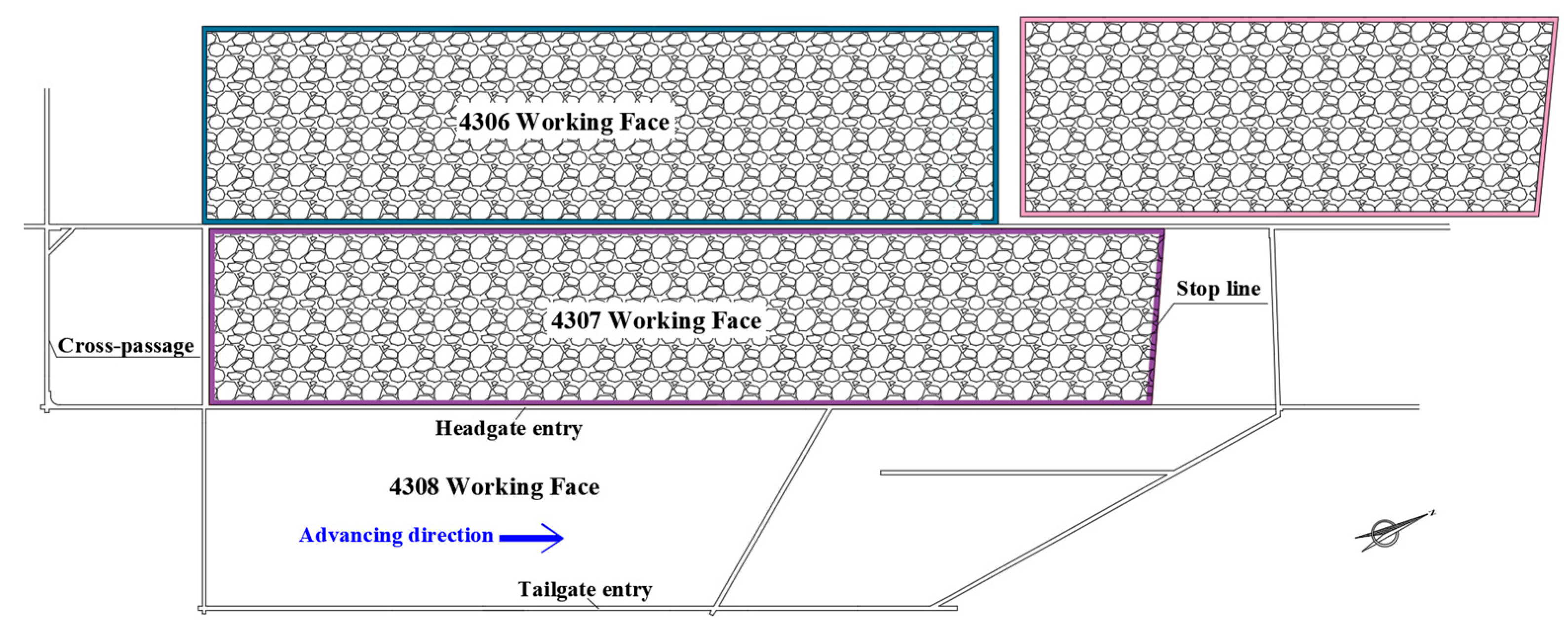
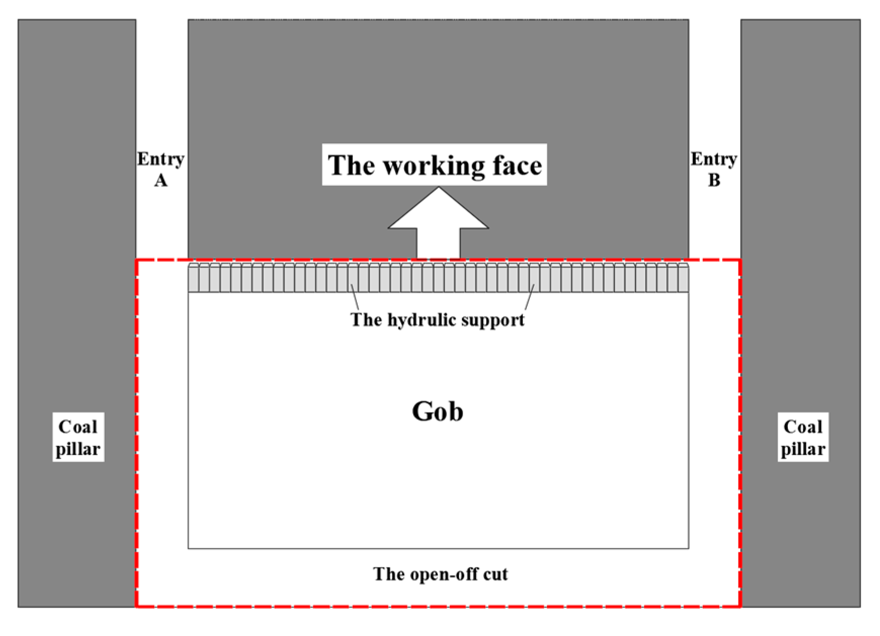
The 4308 working face is bounded by solid coal to the north, south, and east and by the gob of the previously mined 4307 working face to the west. It adopts fully mechanized retreat longwall mining with an inclined layout, and the gob is naturally caved. The layout of the longwall face is shown in Figure 2. The total advance length is approximately 977 m, with an initial width of approximately 207 m. After advancing 710 m, the working face width decreases to 65 m. The headgate and tailgate entries are 1011 m and 1274 m, respectively.
Figure 2.
The layout of the 4308 working face.
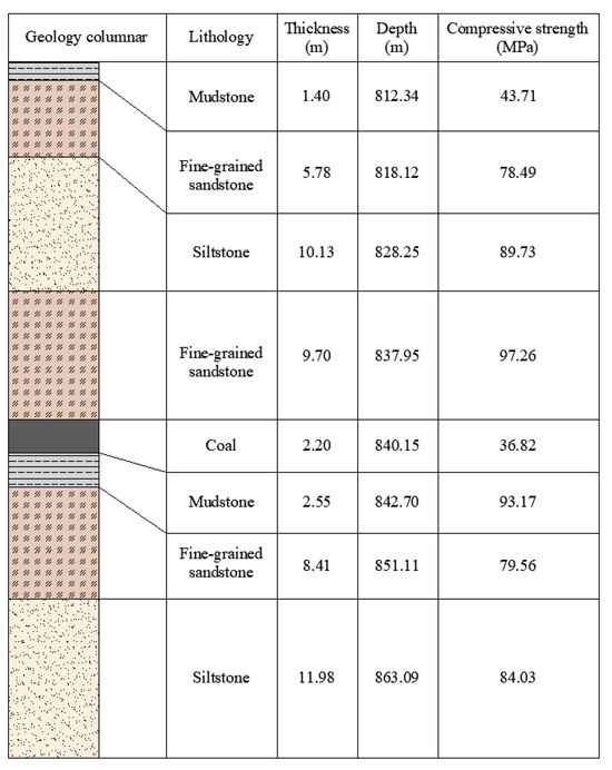
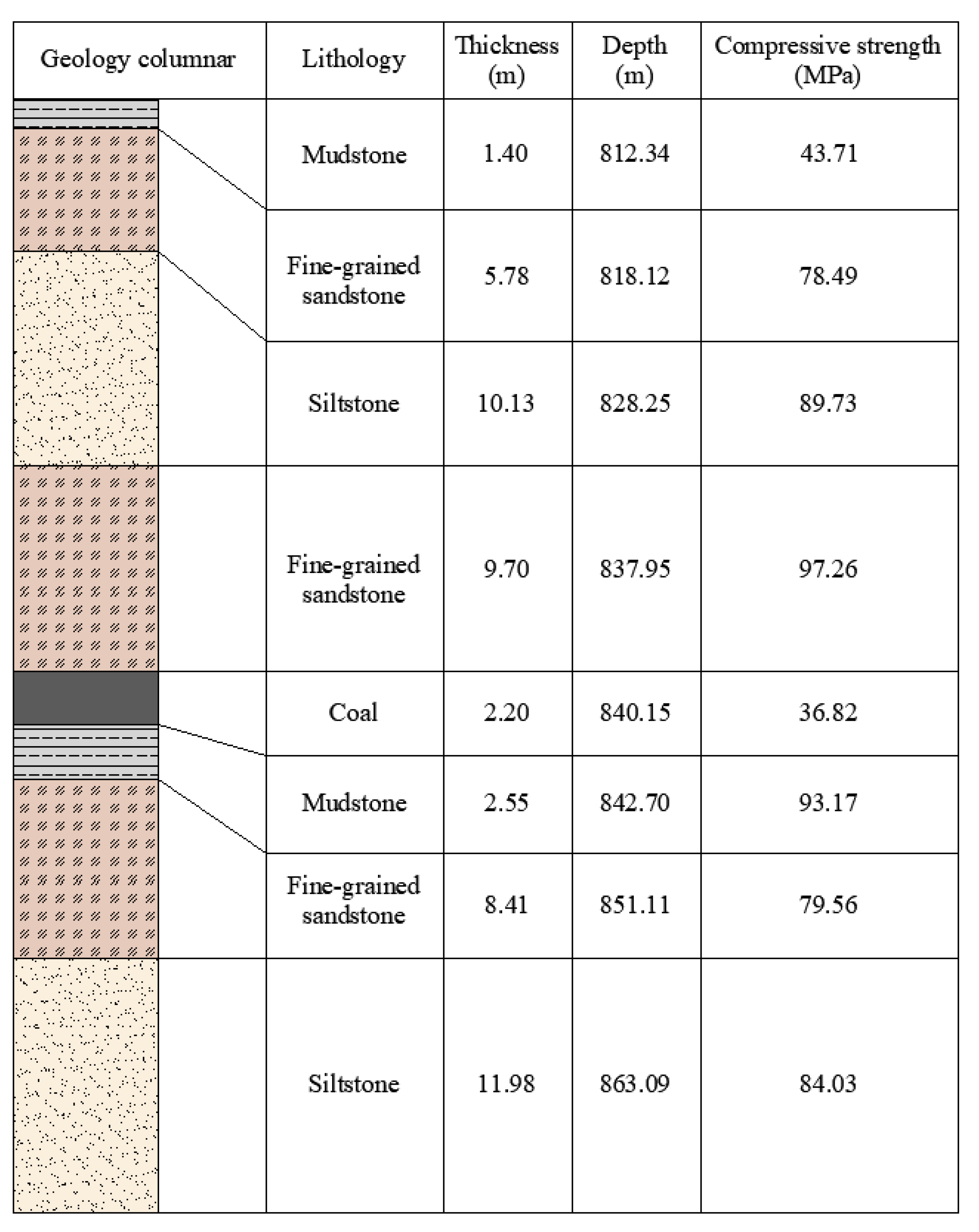
The immediate roof of the 4308 working face consists of fine-grained sandstone, with a thickness of 8.87–10.68 m (average 9.7 m) and a UCS of 72.4–155.1 MPa. The rock is mainly composed of quartz and feldspar. The main roof consists of siltstone with a thickness of 6.0–14.27 m (average 10.0 m) and a UCS of 39.6–114.6 MPa, exhibiting horizontal bedding and relatively intact rock cores.
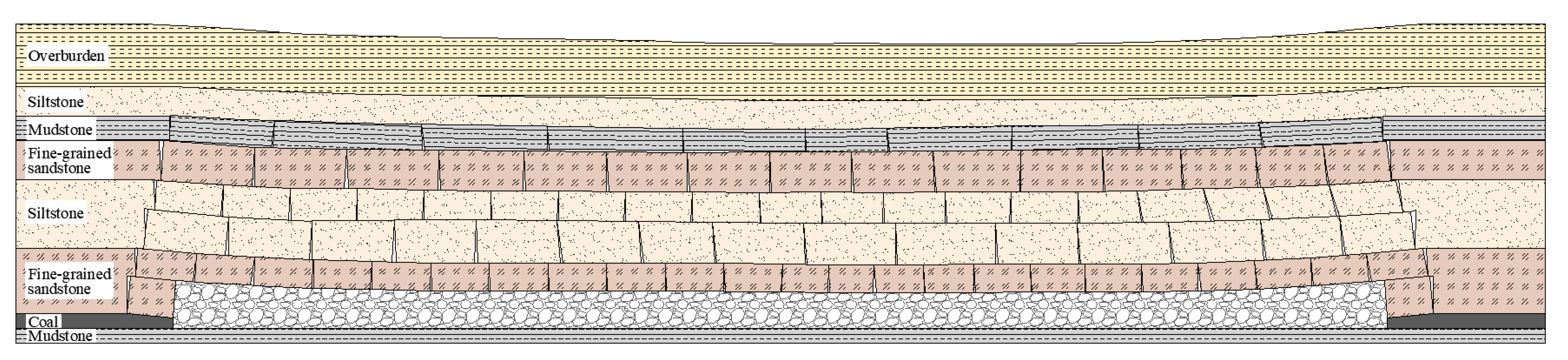
The immediate floor consists of mudstone with a thickness of 2.5–2.6 m (averaging 2.5 m) and a UCS of 82.8–116.1 MPa. Locally, it transitions to siltstone, which is mainly argillaceous with occasional silty characteristics and interbedded fine-grained sandstone layers in the lower section. The main floor consists of fine-grained sandstone with a thickness of 7.73–9.10 m (averaging 8.4 m) and a UCS of 72.4–155.6 MPa, dominated by quartz and feldspar. The detailed distribution of roof and floor strata is shown in Figure 3.
Figure 3.
Stratigraphic column of the roof and floor strata of the 4308 working face.
In summary, both the immediate and main roofs of the 4308 working face consist of hard rock strata with high strength and integrity. During successive working face mining, the gob roof, particularly in the terminal triangular zone, exhibits strong resistance to caving, resulting in an extended suspended roof. This induces intensive strata behavior around the working face and retreat entry, as reflected by significant roof subsidence and coal-wall spalling.
3. Evolution of the Overburden Structure
3.1. Evolution Process
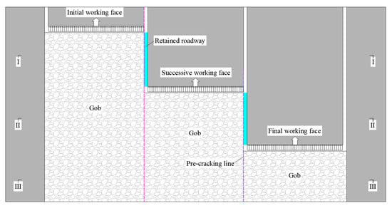
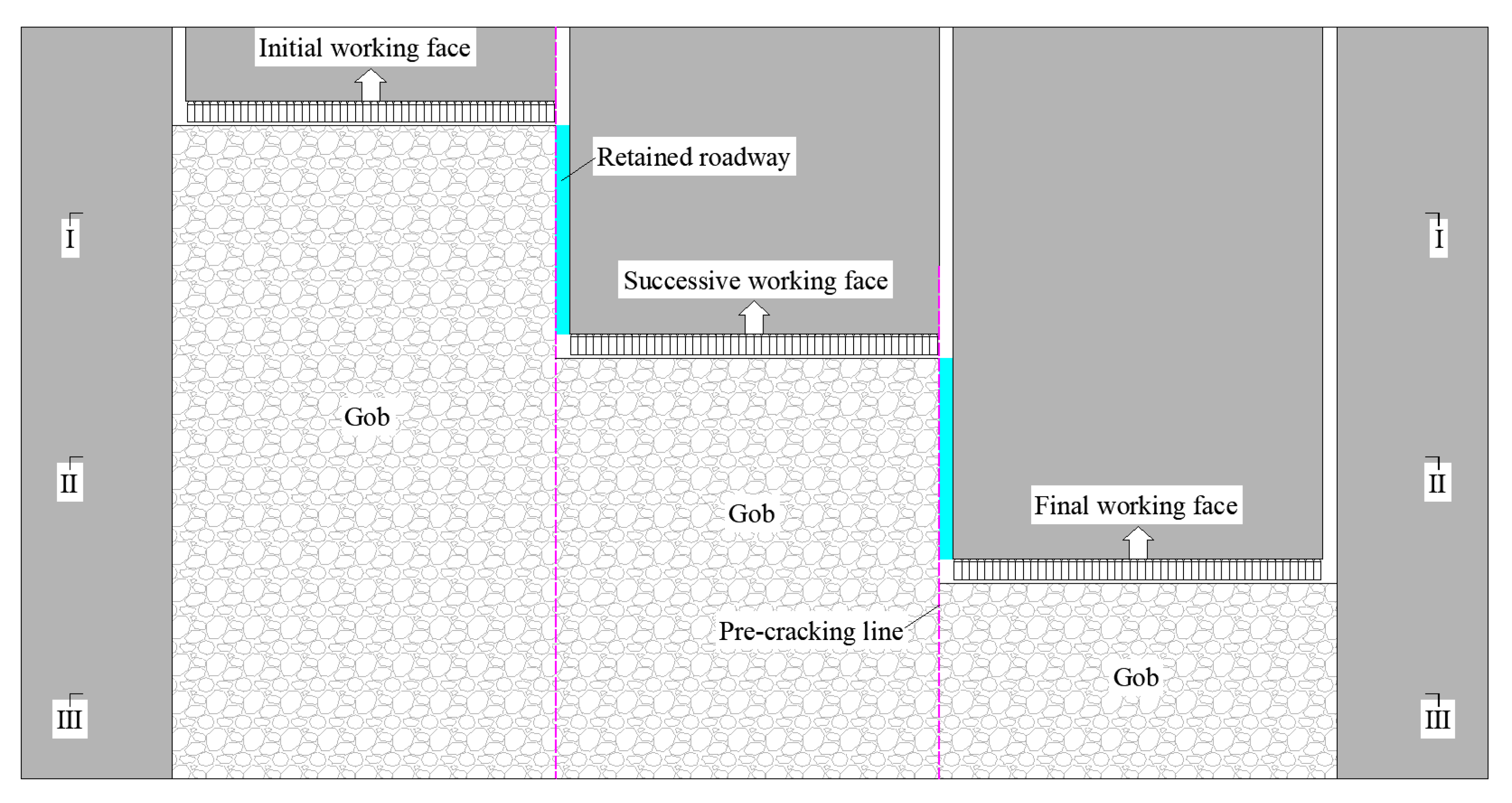
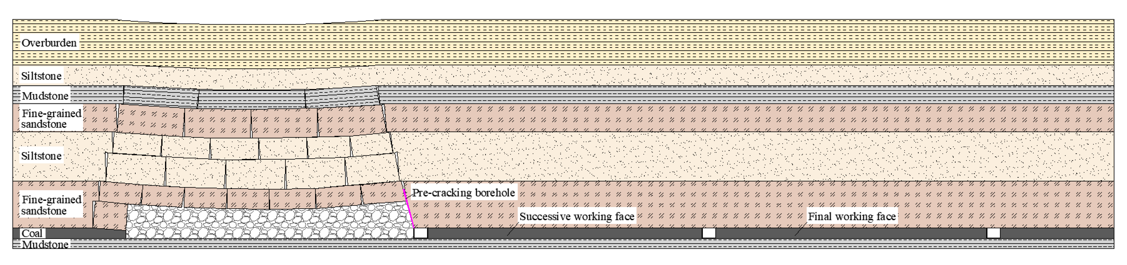
During continuous roof-cutting for entry-retaining and reuse, the spatial relationship between the pre-cracking line and the working face changes with successive face mining and cyclic entry reuse. Accordingly, the roof fracture modes and key-strata load-bearing structure are progressively adjusted. To clarify overburden structural evolution at different mining stages, the entire mining process is divided into three typical stages based on the face advance sequence: the initial, successive, and final working face. The layout of working faces and pre-cracking lines are shown in Figure 4. Due to the different boundary conditions and overburden movement characteristics among these stages, the roof structures exhibit distinct evolutionary features, which are analyzed in the following sections.
Figure 4.
Overburden structures of the working face at different panel mining stages: Section I-I, the extraction of the initial working face; section II-II, the extraction of the successive working face; section III-III, the extraction of the final working face.
- Overburden Structure in Initial Working Face
Before extraction of the initial working face, the mining system is established, with intensive support and roof pre-cracking blasting implemented along the retained-entry side. After face extraction, the immediate roof on the retained-entry side fractures and caves along the pre-cracking line, filling the gob. In contrast, the non-retained-entry side, constrained by the original support system, develops a large-span suspended roof that eventually fractures towards the solid coal side under mining-induced stress. With face advancement, the main roof undergoes periodic fracturing and rotation, accompanied by progressive fracture development in the overlying strata, forming the overburden structure of the initial working face shown in Figure 5.
Figure 5.
Asymmetric overburden structure after mining of the initial working face.
As shown in Figure 5, the overlying strata of the initial working face exhibit distinct asymmetric fracture and subsidence characteristics. On the retained-entry side, a pressure-relief structure characterized by “timely fracturing and caving-induced backfilling” develops, whereas a load-bearing structure characterized by “roof hanging and delayed fracturing” forms on the solid-coal side. These differences in key-strata movement and boundary conditions between the two sides lead to asymmetric roof structure.
This asymmetric roof structure represents the initial stage of overburden structural evolution during roof-cutting entry-retaining and reuse. It provides the structural basis for subsequent adjustment of stope load-transfer pathways and stress migration toward deeper strata.
- 2.
- Overburden Structure in Successive Working Face
After extraction of the initial working face, gob-side entry-retaining was completed and the entry for the successive working face was excavated, establishing an integrated mining system. Meanwhile, roof pre-cracking blasting was conducted above the retained entry. During extraction of the successive working face, the immediate roof on the gob side of the retained entry caved along the pre-cracking line and filled the gob, while the roof above the retained entry fractured and caved synchronously along the pre-existing roof-cutting plane, promoting coordinated pressure relief on both sides of the working face. With continued face advancement, the main roof above the retained entry and the mining area underwent periodic fracture and rotation, accompanied by progressive fracture propagation in the overlying strata. The resulting overburden structure of the successive working face is shown in Figure 6.
Figure 6.
Uniform-subsidence overburden structure after mining of the successive working face.
As shown in Figure 6, the overlying strata of the successive working face evolve from the asymmetric fracture–subsidence structure of the initial working face to a more uniform structure characterized by synchronous caving on both sides. Consequently, roof movement becomes more coordinated and key-strata load-bearing more balanced. This transition promotes more uniform stope load transfer and deeper stress migration under pillar-free mining of two adjacent working faces.
- 3.
- Overburden Structure in Final Working Face
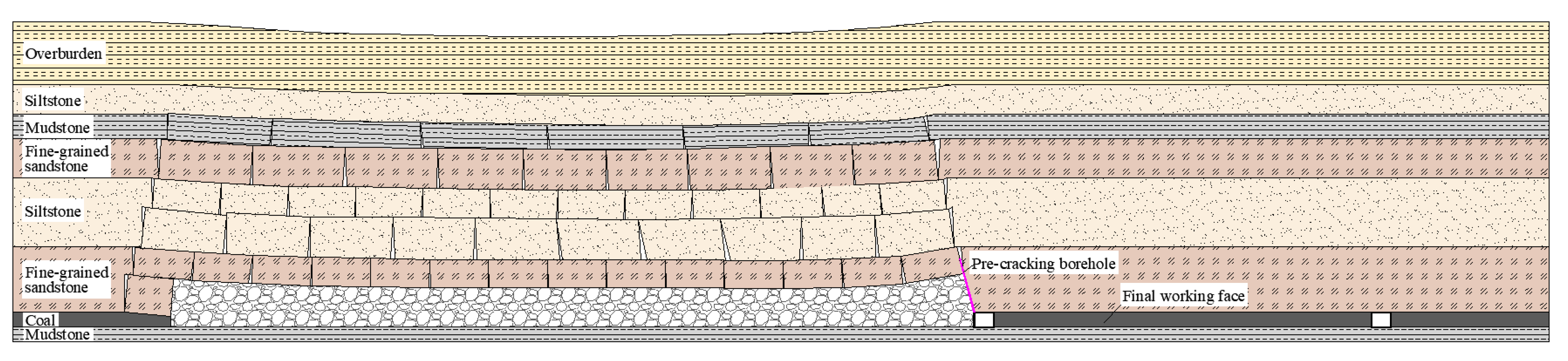
After extraction of the successive working face, gob-side entry-retaining was completed, and the retained entry was reused as the entry for the final working face. During final-face extraction, the roof on the non-retained-entry side fractured and caved above the solid coal, whereas the immediate roof on the retained-entry side fractured along the pre-cracking line, enabling timely caving and adequate gob filling. With continued face advancement, the main roof underwent periodic fracturing and rotation, while overburden fractures propagated and gradually stabilized. The resulting overburden structure of the final working face is shown in Figure 7.
Figure 7.
Coordinated-subsidence overburden structure after mining of the final working face.
As shown in Figure 7, continuous roof-cutting enables the roof strata above each gob to progressively fracture along the predefined cutting lines. Consequently, the overburden movement evolves from local coordination to overall coordination, forming a coordinated-subsidence overburden structure across the whole mining district. Within this structure, key-strata fracture location remains relatively stable, and overburden subsidence becomes more coordinated. Meanwhile, the stope roof load-bearing system tends to stabilize, and mining-induced disturbances gradually dissipate. This evolution provides a stable overburden structure for pillar-free mining and promotes more uniform load transfer within the overlying strata.
In summary, continuous roof-cutting drives overburden structural evolution through three stages: asymmetric fracture and subsidence, uniform subsidence, and coordinate subsidence within the same horizon. As the overburden structure becomes progressively optimized, key-strata movement transitions from uncoordinated to coordinated behavior, accompanied by gradual stabilization of the stope load-bearing system and load-transfer pathways. This evolution provides the basis for subsequent mechanical modeling of overburden structure and analysis of stress-transfer mechanisms.
3.2. Mechanical Models
3.2.1. Coal Pillar Model
In conventional longwall mining, chain pillars of a specified width are retained on both sides of the working face to support the overlying roof together with the surrounding solid coal. The working face and entry layout with chain pillars is shown in Figure 8.
Figure 8.
Overburden structure of the working face under coal pillar mining mode.
As the working face advances, the gob expands, reducing the support provided by the remaining solid coal and causing progressive roof bending and subsidence. Fracturing initiates when the tensile or shear stress exceeds the rock strength. Roof failure develops progressively from the periphery toward the center along the bedding planes and vertically from lower to higher strata.
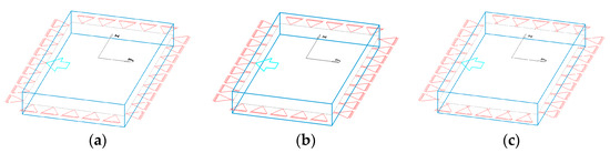
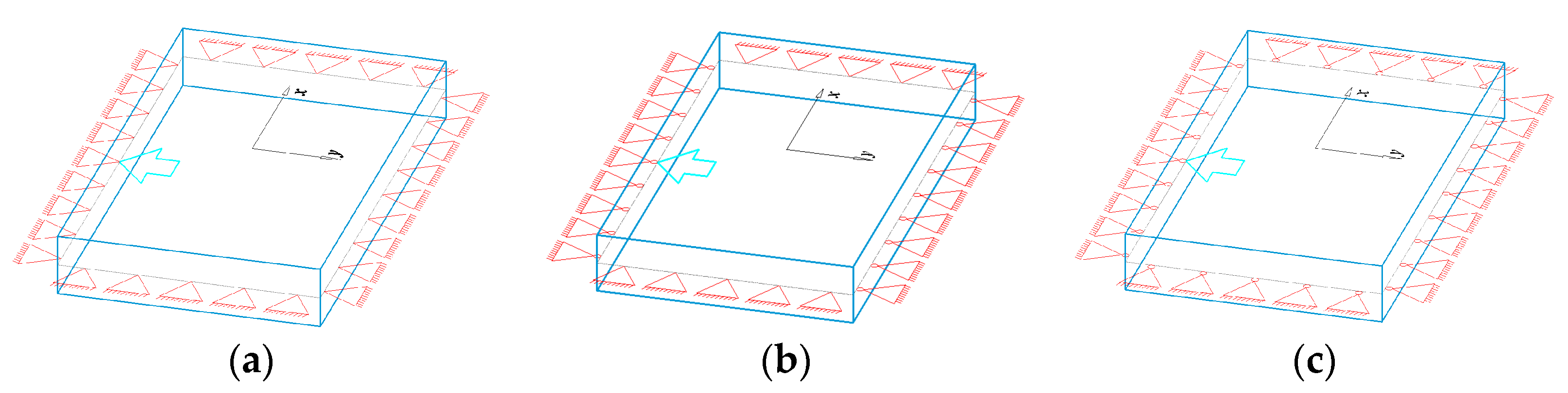
As shown in Figure 8, under conventional coal pillar mining, the roof strata are supported by coal pillars at both ends in the dip direction and by solid coal along the advancing direction. For a mechanical analysis, the roof stratum is isolated, and its initial support condition is depicted in Figure 9a, with all four boundaries idealized as clamped.
Figure 9.
Plate mechanical models of the working face roof strata under conventional coal pillar mining: (a) four-edge clamped boundary condition; (b) two-edge clamped and two-edge simply supported boundary condition; (c) four-edge simply supported boundary condition.
Analytical model assumptions. To obtain an analytically tractable roof model, the target roof stratum is idealized as a homogeneous, isotropic, linearly elastic thin plate of uniform thickness ℎ (m), subjected to a uniformly distributed overburden load q (Pa). A Cartesian coordinate system is established at the plate center, with the x- and y-axes parallel to the long and short sides, respectively. Intact boundaries connected to the surrounding rock mass are idealized as clamped edges because both transverse displacement and rotation are constrained. In contrast, the pre-cracking boundary is idealized as simply supported, representing the substantially reduced bending moment transfer across the pre-cracking plane while partial normal contact and vertical support remain between fractured blocks.
According to elasticity theory, for a four-edge clamped plate, the maximum bending moments and stresses occur near the midpoints of the long sides, where fractures initiate and propagate toward both ends. This converts the long edges from clamped to simply supported, establishing the two clamped–two simply supported model shown in Figure 9b. Subsequent load transfer to the remaining clamped short edges increases their bending moments and stresses, triggering further fracturing and eventually producing the four-edge simply supported model shown in Figure 9c.
Based on the prescribed constraints, the boundary conditions () of the constant-thickness thin plate with four-edge simply supported conditions are defined as follows:
where ω denotes the deflection of the roof structure, m; a represents the length of the long side of the rectangular plate structure, m; and b denotes the length of the short side of the rectangular plate structure, m.
A first-order deflection function satisfying the boundary conditions is established as follows:
where ω1 represents the first-order deflection function of the plate structure, and A1 is a constant in the roof equilibrium equation under coal pillar mining mode, m.
Based on thin-plate bending theory, the total bending potential energy of the working face roof, Ep (J), is derived as follows:
where D represents the flexural rigidity of the plate structure, N·m.
The relationship between Ep and A1 can be expressed in the following form:
The calculation formula for the constant A1 can be derived as follows:
Substituting Equation (5) into Equation (2), the roof deflection function ω is obtained as follows:
Based on the internal bending moment equations, the distribution equations of the roof bending moments (Mx and My) are further derived as follows:
where μ is Poisson’s ratio of the roof strata.
Based on the bending moment equations, the internal stress distribution equations of the rectangular roof plate can be further derived.
The analytical solution identifies regions with concentrated bending moments and tensile stresses. Roof fracturing is assumed to initiate when the maximum tensile stress reaches the tensile strength of the corresponding stratum. Equation (7) shows that the internal bending moments Mx and My reach their maximum values at the roof center (0, 0). Therefore, fractures are expected to initiate from this location and propagate along the x-axis toward both sides (Figure 10c). When the cracks approach the simply supported short boundaries, they bifurcate and produce an “O-X” failure mode of the roof under coal pillar mining (Figure 10d). The overall fracture evolution is illustrated in Figure 10.
Figure 10.
O-X fracturing process of the working face roof under coal pillar mining. (a) Fracturing along the long side; (b) fracturing along the short side; (c) fracturing from the center toward the long-sides; (d) final O-X fracture pattern.
3.2.2. Roof-Cutting Model of the Initial Working Face
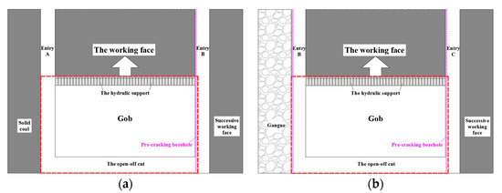
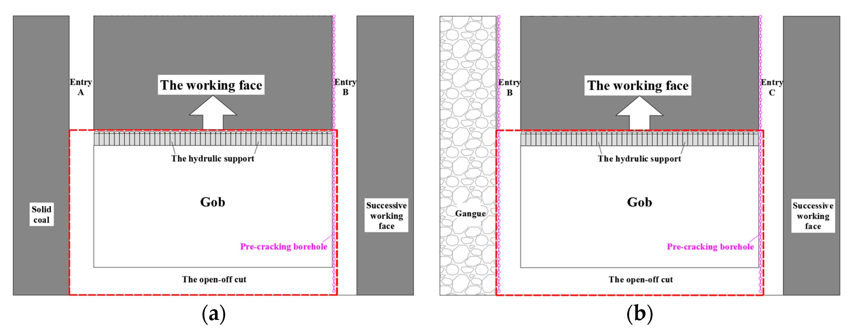
In the single-entry gob-side entry-retaining layout of the initial working face, the working face is bounded by solid coal on both sides, and roof-cutting blasting is conducted along the entry adjacent to the successive working face. After extraction of the initial working face, the retained entry is for the successive working face. The spatial layout of the initial working face and entry arrangement is shown in Figure 11a.
Figure 11.
Overburden structures of the initial and successive working faces under continuous roof-cutting mode: (a) the initial working face; (b) the successive working face.
As shown in Figure 11a, directional roof-cutting blasting is performed along the gob side of entry B. The fracture ratio of blast holes generally ranges from 70% to 90%. Therefore, the roof-cutting boundary is idealized as a simply supported edge. Accordingly, a thin-plate mechanical model of the initial working face roof is established with one simply supported edge and three clamped edges.
Using the same elasticity-based analytical method, the bending moment distribution equations of this roof plate model with one simply supported edge and three clamped edges are derived as follows:
where A2 represents a constant in the roof equilibrium equation under roof-cutting mode, m.
Equation (9) shows that the internal bending moments Mx and My reach their maximum values at the roof center (0, 0). Therefore, roof fracturing is expected to initiate from this location. Due to the directional roof-cutting on one side, the structural strength along the cutting boundary is significantly reduced. Consequently, the fracture propagates from the center toward the roof-cutting side, and bifurcation occurs when the crack approaches the simply supported short boundary, forming a semi-”X” fracture pattern (Figure 12a). The roof above the working face remains load-bearing, while the other two edges progressively fracture and transition into a simply supported condition (Figure 12b).
Figure 12.
O-X fracturing process of the initial working face roof under roof-cutting: (a) fracture propagation from the center toward the roof-cutting side along the long-side; (b) fracturing along the long side; (c) fracture propagates from the center toward the solid-coal side along the long side; (d) final O-X fracture pattern.
With continued deformation of the gob roof, fractures further propagate from the center toward the clamped boundaries, forming a “U-X” fracture pattern (Figure 12c). Under sustained overburden loading, the remaining clamped short edge eventually fractures, resulting in the final “O-X” roof failure pattern (Figure 12d).
3.2.3. Roof-Cutting Model of the Successive Working Face
During extraction of the successive working face, one entry was the retained entry from the previous working face after roof-cutting, while advance roof-cutting blasting was performed along the other entry. Thus, a double-entry roof-cutting layout was established for the successive working face, as shown in Figure 11b.
After roof-cutting along both entries, the roof initially exhibited a plate structure with two simply supported short edges and two clamped long edges (Figure 13a). Mechanical analysis indicates that the maximum bending moment and stress are concentrated at the midpoint of the clamped long edges. Accordingly, fractures initiate at these locations and propagate toward both ends. With further development of the fractures, the roof plate evolves into a four-edge simply supported structure (Figure 13b).
Figure 13.
O-X fracturing process of the successive working face roof under roof-cutting. (a) Fracturing along the short sides; (b) fracturing along the long sides; (c) fracture propagation from the center toward the long sides; (d) final O-X fracture pattern.
For the four-edge simply supported plate, subsequent fracture evolution follows the same process as that of the roof reaching the four-edge simply supported state under coal pillar mining, as shown Figure 13c,d.
In summary, roof-cutting regulates roof fracture initiation and propagation by modifying the boundary conditions of the working face roof. It transforms the conventional central outward-propagating “O-X” fracture pattern under coal pillar mining into an asymmetric fracture pattern with directional propagation characteristics, enabling active control of roof fracture locations. Meanwhile, the short cantilever structure formed after roof pre-cracking promotes overburden load transfer from concentrated bearing by coal pillars and solid coal to the gob and deep coal mass, thereby reducing local stress concentration. Furthermore, the stable block structure formed after roof-cutting enhances coordinate roof movement and improves overburden structural stability, providing a basis for rockburst risk mitigation.
4. Coupled Mechanism of Rockburst Control
4.1. Dynamic Behavior of Short Cantilever Beam
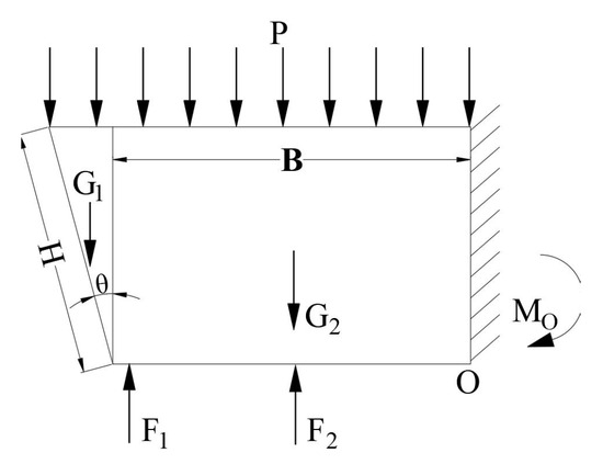
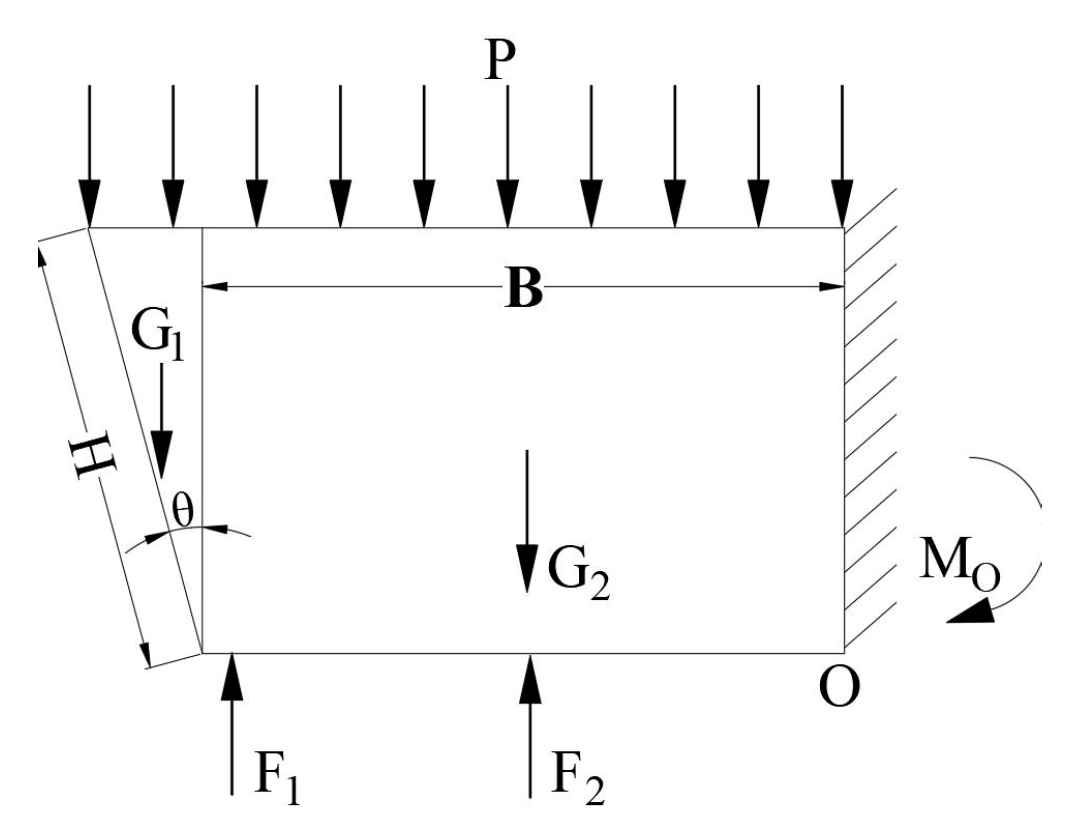
During roof-cutting entry-retaining, main-roof fracture is a key factor affecting the stability of the entry surrounding rock. Therefore, roof loading must be quantified to provide a theoretical basis for roof control design. Because roof-cutting separates the immediate roof from the adjacent strata, the resulting structure can be idealized as a short cantilever beam, as shown in Figure 14.
Figure 14.
Short cantilever beam model of the immediate roof after roof-cutting: P: impact force from the fractured main roof on the immediate roof, kN/m; F1: support force provided by high-strength cables, kN; F2: temporary support resistance in the entry, kN; G1: self-weight of the triangular cantilever region, kN; G2: self-weight of the rectangular cantilever region, kN; M0: bending resistance moment of the short cantilever beam, kN·m; H: roof-cutting borehole depth, m; B: gob-side entry width, m; θ: roof-cutting borehole inclination, °.
When severe deformation is absent, the roof system satisfies moment equilibrium, expressed as follows:
where MF1, MF2 and MF2 are the moments about point O generated by the high-strength cable force F1, temporary support resistance F2, and main-roof load P, respectively (kN·m). These moments are calculated as follows:
MF1 + MF2 + MO = MP + MG,
MF1 = F1B,
In Equation (13), kz represents the dynamic load coefficient of the main-roof force; HE is the main-roof thickness, m; γ2 is the main-roof bulk density, kN/m3; and d is the lateral fracture span of the main roof, m.
Continuous roof-cutting converts the entry roof into a short cantilever beam, reducing the suspended roof span and promoting timely caving. Consequently, the dynamic load coefficient kz transmitted from the main roof decreases, thereby reducing the dynamic loading on the retained entry.
MO is calculated according to Equation (14).
where σm represents the maximum tensile stress within the short cantilever beam, MPa.
The bending moment MG generated by the cantilever beam self-weight about point O is expressed as follows:
where γ1 represents the bulk density of the short cantilever beam, kN/m3.
Substituting Equations (11)–(15) into Equation (10) yields:
During periodic weighting of the main roof under roof-cutting entry-retaining, the structural boundaries are idealized as one clamped edge and one hinged edge, with the retained-entry side treated as hinged. Based on plastic limit analysis of plates, the lateral fracture span d of the broken main roof is related to the working face width Lm (m) and periodic weighting interval Lp (m) as follows:
where km and d0 can be calculated using Equations (18) and (19), respectively.
d = kmd0,
For the 4308 working face at Guotun Coal Mine, Lm = 207 m and Lp = 14 m. Substituting these values into Equation (17) gives a lateral fracture span d of 23.8 m.
The minimum tensile strength of the short cantilever beam strata is 1.6 MPa. With a safety factor of 4, the allowable tensile stress σm within the rock beam is determined to be 0.4 MPa.
Substituting the relevant parameters into Equation (16) gives a required temporary support force F2 of 659 kN. The field support resistance is designed as 1020 kN, satisfying the roof stability requirements.
4.2. Dual-Arch Structure
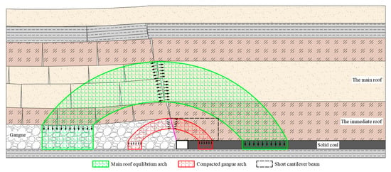
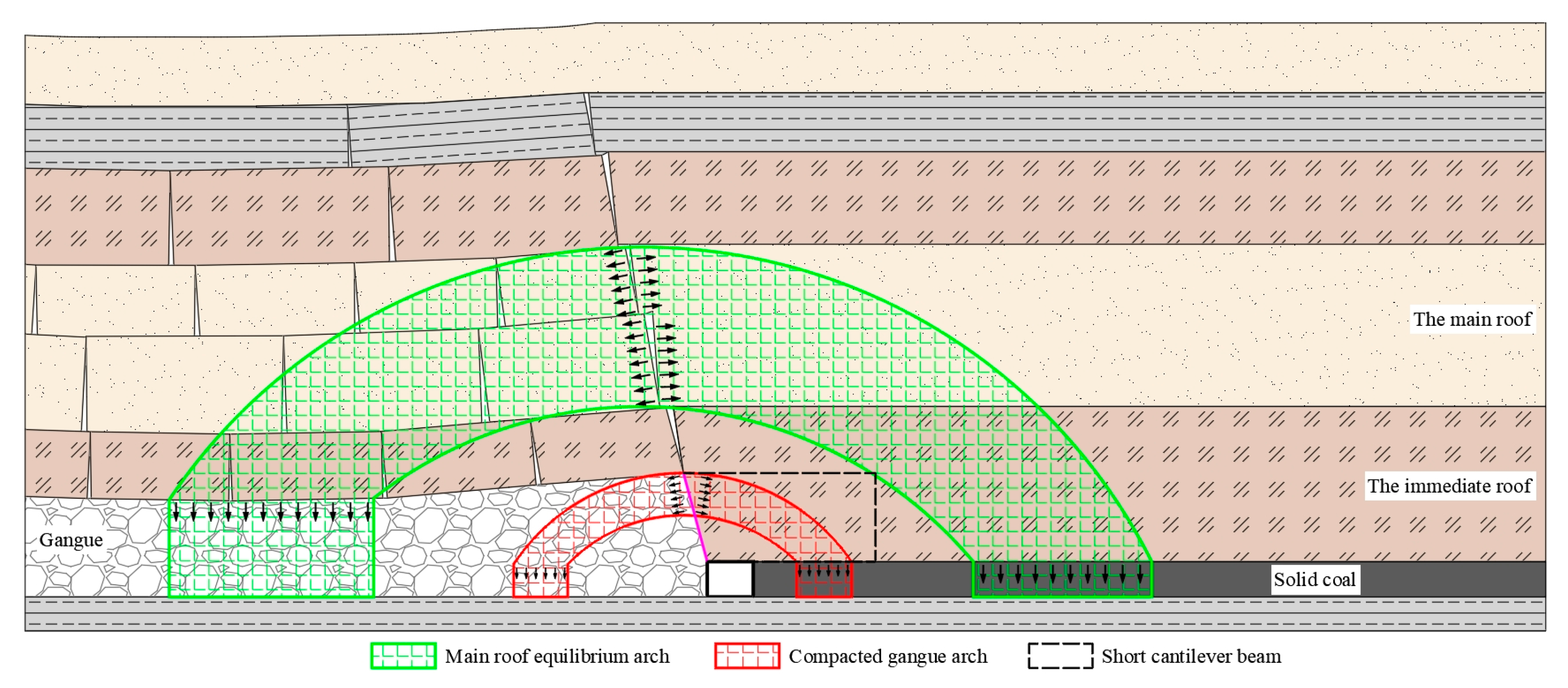
Based on the preceding overburden evolution and mechanical analysis, a conceptual dual-arch bearing model is proposed to interpret the reconstructed load-transfer system after continuous roof-cutting. As gob gangue progressively compacts and the main roof fractures and stabilizes, overburden load evolves from single-stratum dominance to coordinated multilayer bearing. The lower compacted gangue arch is formed by the interaction between the short cantilever beam and compacted gangue, while the upper main-roof equilibrium arch develops through the articulation of fractured main-roof blocks. Together, these two conceptual arches form the proposed dual-arch load-bearing structure above the retained entry, as shown in Figure 15. Specifically, the lower gangue arch primarily supports the immediate roof load and restricts the surrounding rock deformation, whereas the upper equilibrium arch mainly carries main-roof loading and maintains the overall overburden stability.
Figure 15.
Dual-arch collaborative load-bearing structure for roof-cutting entry-retaining.
The structural evolution and stress redistribution of the dual-arch collaborative load-bearing structure exhibit distinct stage-dependent characteristics. Therefore, the evolution process is divided into four stages, and the corresponding formation mechanisms are systematically discussed below.
- (1)
- Roof-cutting Stage
Before working face extraction, directional roof-cutting is performed along the entry in advance. After working face retreat, the immediate roof caves along the pre-cracking line, transforming the original continuous cantilever beam into a short cantilever beam structure.
- (2)
- Formation Stage of the Compacted Gangue Arch
Under overburden loading, gob gangue is progressively compacted, increasing its load-bearing capacity. Together with the short cantilever beam, the compacted gangue contributes to the formation of a lower arch-bearing structure supported by the solid coal and compacted gangue.
- (3)
- Formation Stage of Main-Roof Equilibrium Arch
When the main roof reaches its critical span, it fractures, and the broken rock blocks interlock to form an equilibrium arch. With the solid coal and deep compacted gangue acting as arch feet, this structure becomes an important load-bearing component of the overburden.
- (4)
- Dual-arch Cooperative Bearing Stage
The lower compacted gangue arch and upper main-roof equilibrium arch together constitute the proposed dual-arch coordinated bearing structure, enabling multilevel overburden load transfer, stress redistribution, and energy dissipation, thereby contributing to long-term entry surrounding rock stability.
Under the roof-cutting and entry-retaining condition, the proposed dual-arch collaborative bearing structure provides a conceptual framework for interpreting the reconstruction of the overburden bearing system and load-transfer pathways. In conventional coal pillar mining, overlying strata loads are mainly transferred through the “main-roof–immediate roof–coal pillar (entry)” pathway, resulting in stress concentration around the coal pillar and entry. After roof-cutting, the overburden load is redistributed toward the solid coal and compacted gangue in the gob through the proposed dual-arch load-transfer system. The participation of compacted gangue in bearing capacity reduces the load concentration around the entry and promotes stress migration into deeper strata, thereby contributing to a more distributed stress environment.
In terms of dynamic loading, the proposed dual-arch mechanism suggests that the upper main-roof equilibrium arch can provide initial buffering through the rotation, extrusion, and frictional interaction of articulated blocks, while the lower compacted gangue arch contributes to impact energy dissipation through gangue crushing, fracture closure, and frictional sliding.
Therefore, this conceptual describes a progressive energy regulation process characterized by “upper arch buffering–lower arch transfer–gangue dissipation.” The numerical and field observations support this interpretation by demonstrating reduced stress concentration and more distributed energy release under continuous roof-cutting conditions.
4.3. Stress Transfer and Redistribution
Based on the geological and mining conditions of the 4307 and 4308 working faces in Guotun Coal Mine, a three-dimensional distinct element model was established using 3DEC. The model dimensions were 500 m × 150 m × 115 m along the x, y, and z directions, respectively. The No.3 coal seam, with an average thickness of 2.2 m, was excavated according to the actual mining sequence. Rock mechanics parameters were obtained from the field sample test and are listed in Table 1. The initial stress field was established considering the self-weight of the overlying strata and a vertical stress of 19 MPa applied to the upper boundary to represent the equivalent overburden load above the modeled strata. Normal displacement constraints were applied to the lateral boundaries, and the bottom boundary was fixed vertically.
Table 1.
Mechanical parameters of surrounding rocks.
The rock strata were modeled using the Mohr–Coulomb constitutive model, and interface elements governed by the Coulomb-slip criterion were introduced between rock layers and along the roof-cutting plane. A graded zoning scheme was adopted, with refined blocks assigned to the coal seam, retained entry, and roof-cutting region. The roof-cutting plane was arranged along the gob-side roof of the retained entry, with a cutting depth of 7.5 m and an inclination angle of 15°.
To evaluate the effect of roof-cutting entry-retaining on the surrounding rock stress environment of entries, two comparative schemes were designed. Scheme 1 employed the roof-cutting pressure-relief method, whereas Scheme 2 represented conventional coal pillar mining with a 6 m wide coal pillar retained between the 4307 and 4308 working faces. The excavation sequence followed the actual mining process, including extraction of the 4307 working face followed by the successive extraction of the 4308 working face.
- (1)
- Roof-cutting in the Initial Working Face
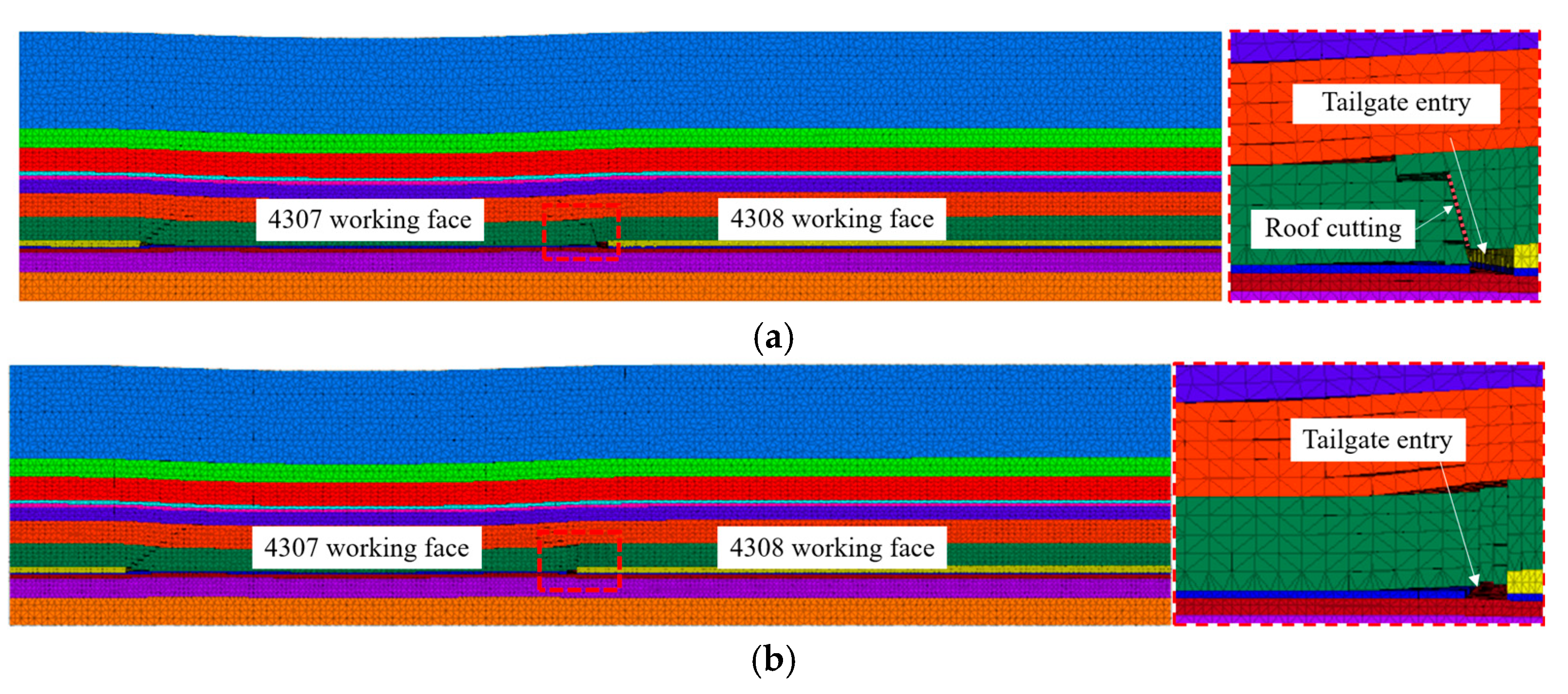
Under the entry-retaining scheme, the retained state of the 4307 tailgate entry after mining is shown in Figure 16a. Following roof-cutting, the overlying strata above the 4307 gob caved along the roof-cutting line. This promoted timely gob filling and mobilized the load-bearing capacity of caved gangue to support the overlying strata.
Figure 16.
Caving characteristics of the overlying strata after extraction of the 4307 working face: (a) roof-cutting above the entry; (b) natural caving of the entry roof.
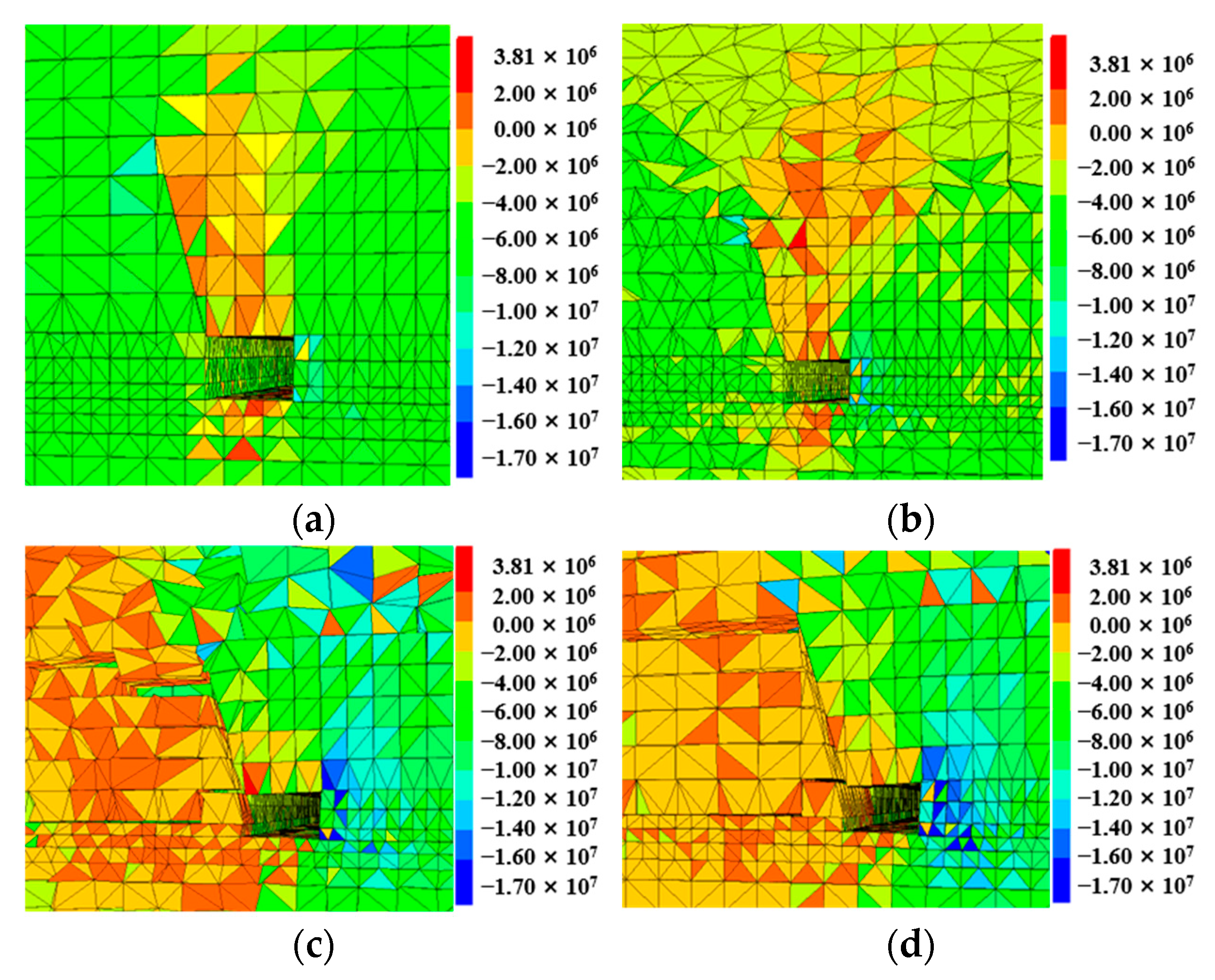
To evaluate the influence of 4307 working face extraction after roof-cutting on the retained entry, the vertical stress distribution around the entry at different locations was analyzed (Figure 17).
Figure 17.
Vertical stress distribution around the retained entry: (a) 20 m ahead of the working face; (b) 5 m ahead of the working face; (c) 5 m behind the working face; (d) 20 m behind the working face.
As shown in Figure 17a,b, the advanced zone ahead of the working face exhibits relatively high lateral abutment pressure on the solid-coal side of the retained entry, and stress concentration increases with face advancement. The distinct vertical stress difference across the roof-cutting plane indicates that the pre-cracking locally interrupts roof load transfer and reduces the load transferred to the retained entry. As shown in Figure 17c,d, behind the working face, lateral abutment pressure on the solid-coal side becomes dominant, resulting in significant stress concentration. With increasing distance behind the working face, the concentrated stress zone gradually migrates deeper into the solid coal.
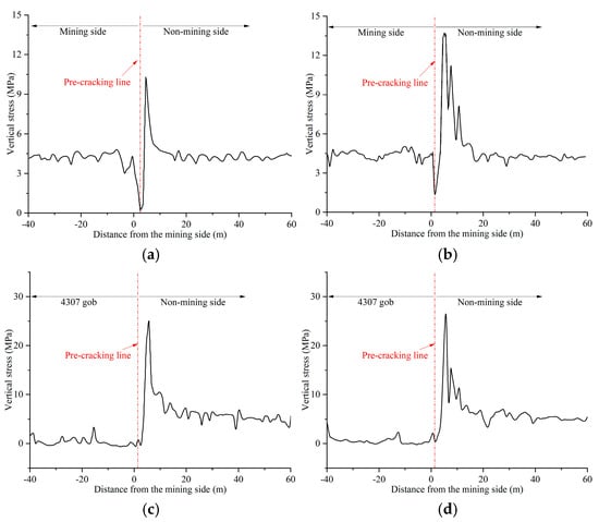
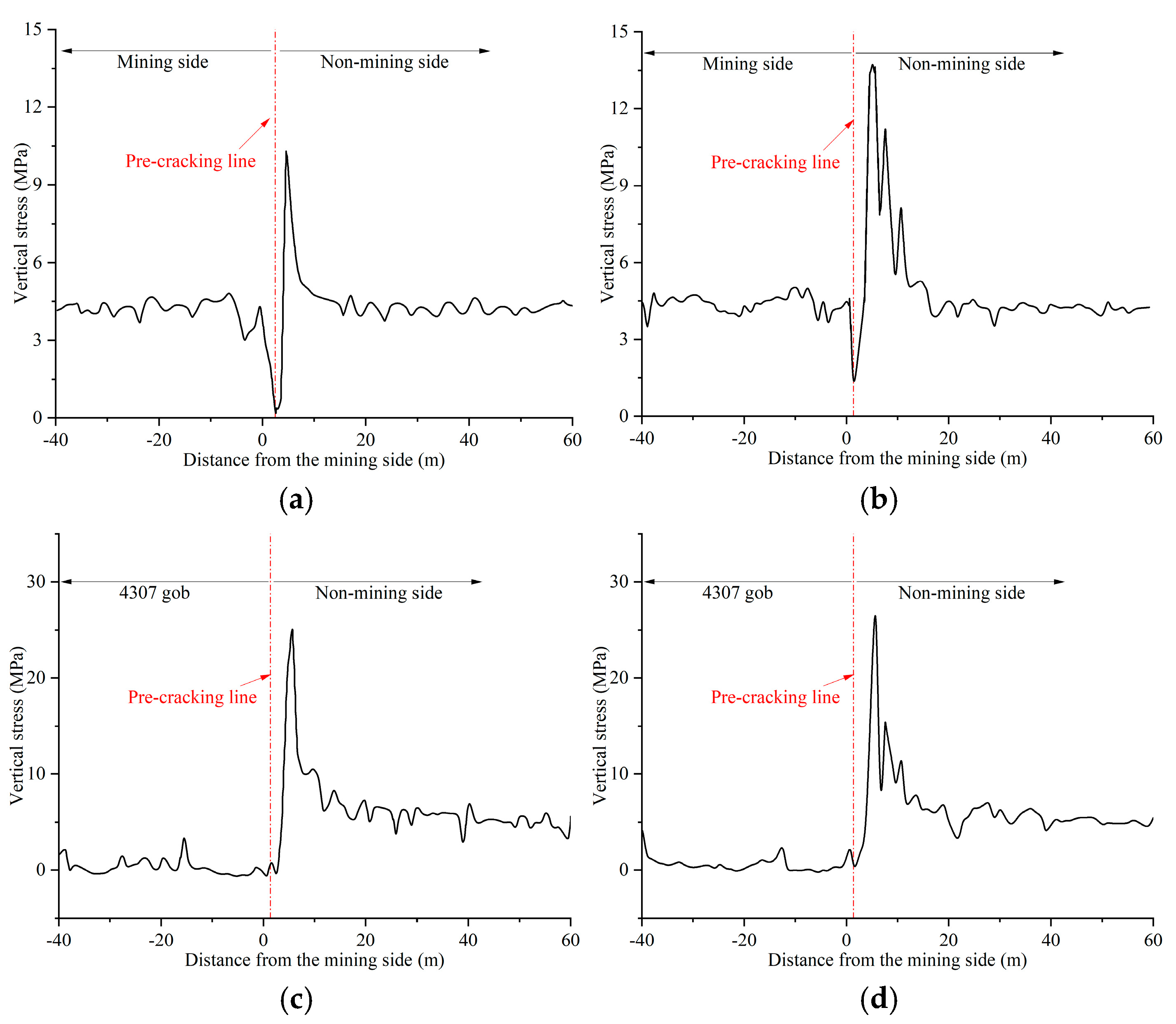
Figure 18 shows the evolution of lateral abutment pressure during the roof-cutting gob-side entry-retaining process. As shown in Figure 18a,b, the abutment pressure on the solid-coal side ahead of the working face is significantly higher than that on the mining side. A low-stress zone develops on the mining side due to roof-cutting-induced pressure relief, indicating that part of the roof load is transferred toward the solid coal after roof-cutting. Considering the advanced abutment pressure, the pressure on the solid-coal side reaches 13.0 MPa at 5 m ahead of the working face. As shown in Figure 18c,d, behind the working face, the abutment pressure on the solid-coal side of the retained entry is significantly higher than that ahead of the working face, reaching a peak value of 26.2 MPa at 20 m behind the working face. Meanwhile, stress recovery occurs progressively within the caved gangue in the gob.
Figure 18.
Distribution of lateral abutment pressure along both sides of the retained entry: (a) 20 m ahead of the working face; (b) 5 m ahead of the working face; (c) 5 m behind the working face; (d) 20 m behind the working face.
- (2)
- The Initial Working Face under Coal pillar Mining
In the conventional coal pillar mining scenario, the overburden caving behavior after extraction of the 4307 working face is shown in Figure 16b. The gob roof on the tailgate-entry side does not cave promptly; instead, it undergoes overall deflection toward the gob, continuously imposing pressure on the chain pillar.
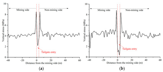
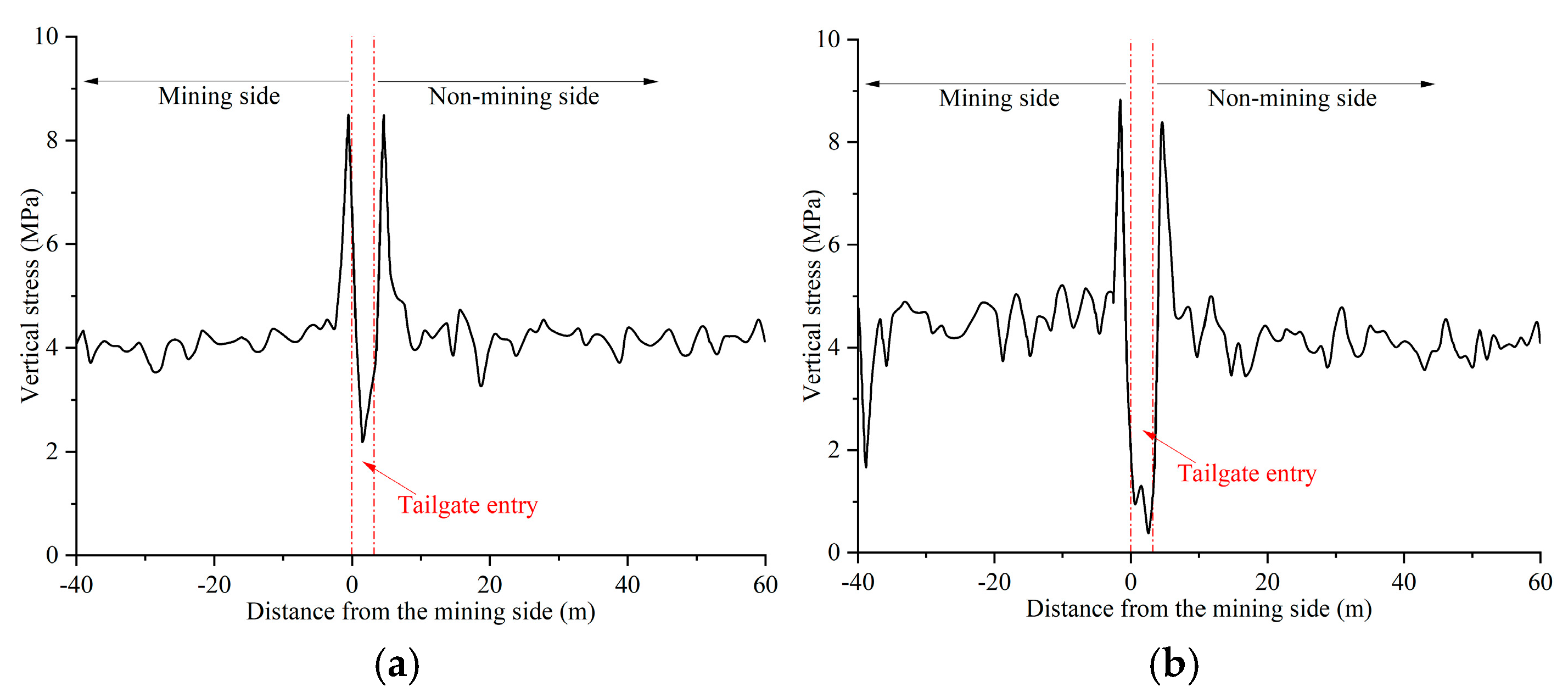
The lateral abutment pressure distribution along the tailgate entry under coal pillar mining is shown in Figure 19. Mining-induced high-abutment-pressure zones develop on both sides of the entry, and the peak pressure increases progressively as the working face approaches. The lateral abutment pressure on the mining side is significantly higher than that under the roof-cutting condition, indicating the pressure-relief effect of roof-cutting.
Figure 19.
Distribution of lateral abutment pressure on both sides of the entry under the pillar retention condition: (a) 20 m ahead of the working face; (b) 5 m ahead of the working face.
- (3)
- The Successive Working Face with Entry Reuse
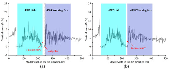
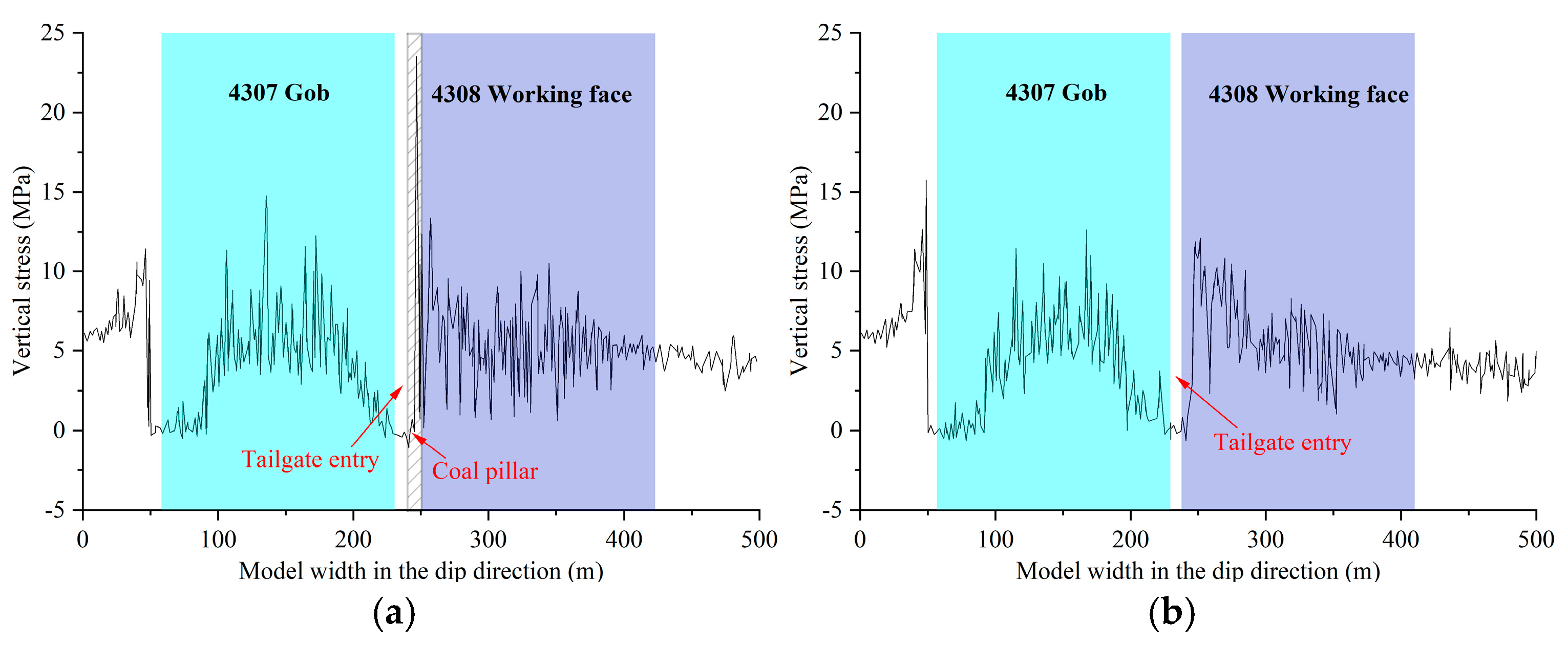
During extraction of the 4308 working face, the 4307 tailgate entry undergoes secondary mining effects. The lateral abutment pressure distribution under the roof-cutting entry-retaining and conventional pillar schemes, affected by the combined action of the 4307 working face lateral abutment pressure and the 4308 working face advance abutment pressure, is shown in Figure 20. Comparison of Figure 20a,b reveals that, at 5 m ahead of the working face, the peak abutment pressure in the coal pillar reaches 23.5 MPa, approximately 1.9 times that of the surrounding rock in the roof-cutting entry-retaining scheme. This results in intense stress concentration within the coal pillar and indicates increased rockburst susceptibility. In contrast, the reused entry under the roof-cutting scheme exhibits a maximum solid-coal-side abutment pressure of 12.1 MPa and a distinct low-stress zone near the entry. These characteristics demonstrate a more favorable stress environment than the coal pillar scheme and contribute to reduced energy accumulation and rockburst risk.
Figure 20.
Lateral abutment pressure distribution at 5 m ahead of the 4308 working face: (a) coal pillar scheme; (b) roof-cutting entry-retaining scheme.
The numerical model focuses on overburden stress redistribution and structural evolution induced by continuous roof-cutting rather than the complete progressive damage process of intact rock. Therefore, the Mohr–Coulomb constitutive model and interface elements were adopted to characterize the elastoplastic response of the rock mass and the discontinuous deformation along the roof-cutting plane based on the geological and mining conditions of the 4308 working face. The simulated overburden deformation and stress redistribution are consistent with the observed structural behavior, and the reduction in peak abutment pressure under the roof-cutting scheme provides numerical evidence for the proposed load-transfer and pressure-relief mechanism.
5. Microseismic Response and Rockburst Risk Assessment Under Continuous Roof-Cutting
5.1. Microseismic Analysis of the 4308 Working Face
Field microseismic monitoring was conducted to characterize the in-situ seismic response during continuous roof-cutting mining and evaluate its consistency with the proposed overburden evolution and stress-transfer mechanism.
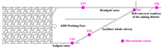
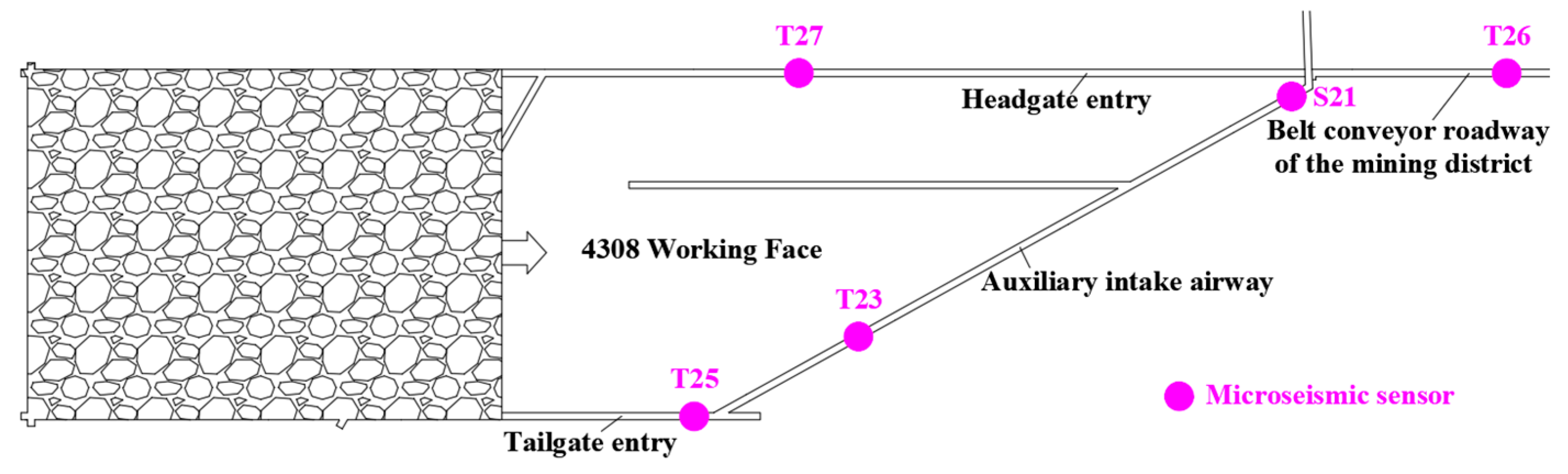
A microseismic monitoring system was established at the 4308 working face during mining. The system consisted of five underground sensors installed in the headgate, tailgate, and surrounding entries, with the sensor layout shown in Figure 21. One sensor was installed in each of the tailgate entry and headgate entries, two sensors were arranged in the auxiliary intake airway of the No. 4 mining district, and one sensor was installed in the corresponding belt conveyor entry. This sensor array effectively covers the face advance zone. The sensor lead distance in both entries ahead of the working face was maintained below 100 m, and the spacing between adjacent sensors was less than 300 m.
Figure 21.
Layout scheme of microseismic sensors for the 4308 working face.
The monitoring period covered the entire mining process from May 2024 to September 2025. Microseismic events were automatically detected and located using the mine microseismic monitoring system based on seismic waves arrival-time differences. Event energy was calculated by the system from the recorded waveform characteristics.
As the working face advanced, microseismic sensors were synchronously relocated to maintain continuous and comprehensive monitoring during continuous mining. Microseismic early-warning indicators were established according to Table 2.
Table 2.
Microseismic monitoring warning criteria during mining of the 4308 working face.
All analyzed microseismic events were recorded after the completion of industrial pre-cracking blasting. All blasting-induced signals were removed according to their occurrence time and waveform characteristics provided by the ESG monitoring system.
5.2. Temporal Evolution Characteristics of Microseismic Activity
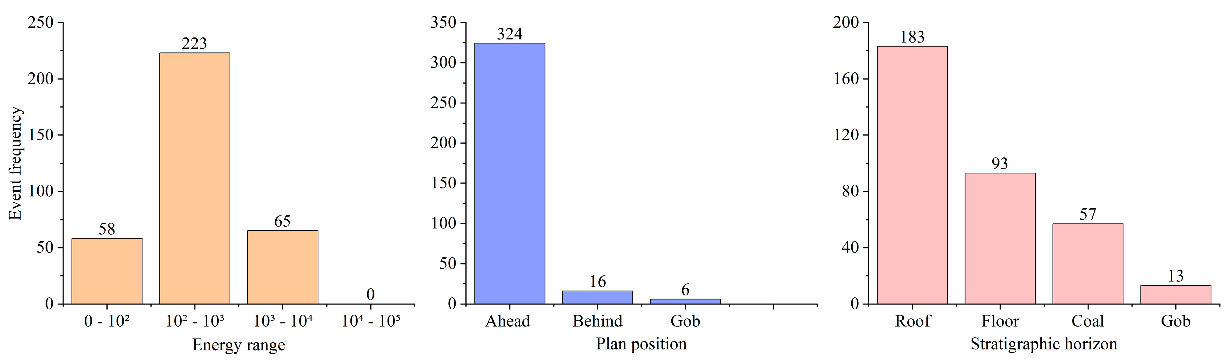
Microseismic sensors arrayed around the working face recorded the energy, planar coordinates, and stratigraphic locations of microseismic events during the mining of the 4308 working face; the corresponding statistical distributions are shown in Figure 22.
Figure 22.
Frequency distribution of microseismic events at different energy levels, plan positions, and stratigraphic horizons.
Figure 22 shows that 58 microseismic events occurred in the 0–1 × 10² J range, accounting for 16.76% of the total events; 223 events fell within the 1 × 10²–1 × 10³ J range (64.45%), and 65 events were within the 1 × 10³–1 × 10⁴ J range (18.79%). The maximum microseismic energy was below 1 × 10⁴ J. According to the warning criteria listed in Table 2, low-energy microseismic events dominated during working face extraction, indicating a relatively low risk of rockburst.
Microseismic events ahead of the 4308 working face accounted for 93.64% of all recorded events during mining, indicating that roof-cutting promoted timely immediate roof caving along the pre-cracking line and reduced stress transfer from the gob roof to the entry roof.
Microseismic events occurring inside the roof strata accounted for 52.89% of the total events during the mining of the 4308 working face, indicating that roof strata were the main region of mining-induced fracturing activity. This spatial distribution is consistent with the effect of continuous roof-cutting in promoting directional roof deformation and fracture development. Furthermore, the subsequent roof movement was characterized mainly by low-energy microseismic events, suggesting that the roof failure process was relatively progressive and that no significant high-energy failure events associated with large-scale roof instability were detected during the monitoring period.
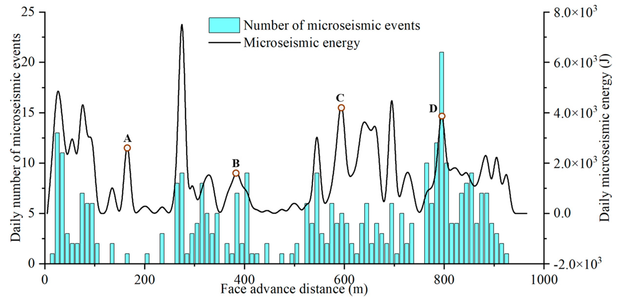
The energy and frequency of microseismic events are commonly used parameters for characterizing mining-induced seismic activity. Generally, higher-energy microseismic events may represent larger-scale rock fracturing and greater local energy release, whereas event frequency reflects the temporal intensity of fracture activity within the monitored area. The daily total energy and frequency distributions of microseismic events during mining were obtained using a one-day statistical interval, as shown in Figure 23.
Figure 23.
Temporal evolution of microseismic event energy (J) and frequency.
According to Figure 23, the microseismic energy exhibited a periodic high–low–high variation pattern. The energy and frequency of microseismic events showed four noticeable distinct concentration stages, which were associated with the single-working-face squaring (Point A), two-working-face squaring (Point B), three-working-face squaring (Point C), and the final mining period (after Point D), respectively. Among these stages, the maximum observed microseismic energy occurred at point C, although it remained below 1 × 10⁴ J. This suggests that mining-induced disturbance associated with the squaring stage was still observable after continuous roof-cutting. This behavior may be related to the progressive roof caving and gob filling promoted by roof-cutting, which is consistent with a relatively gradual evolution of overburden fracture and movement.
The temporal variations in microseismic energy and frequency did not show a fully synchronous evolution during the mining process. During the single-working-face squaring period, microseismic events were characterized by a relatively high-energy and low-frequency response, which may be related to the relatively large initial caving interval of the main roof and the concentrated release of mining-induced energy. During the two-working-face squaring period, microseismic events exhibited a relatively high-frequency and low-energy response, suggesting that fracture activity within the overburden became more active after roof-cutting, while the energy magnitude of individual microseismic events remained relatively limited.
No high-energy microseismic events were detected during the working face squaring period, which may be related to the changes in the roof failure behavior and overburden load-transfer characteristics after continuous roof-cutting. Roof-cutting promoted a transition of the main-roof failure behavior from large-span overall fracturing towards progressive fracture of a short cantilever structure, which may contribute to limiting the energy release associated with individual roof fracture events. Meanwhile, the observed microseismic response was consistent with the proposed development of a dual-arch collaborative bearing structure, in which the overlying load was redistributed and jointly carried by the caved gangue and surrounding coal mass, potentially promoting a more gradual release of mining-induced energy during the working face squaring period.
5.3. Spatial Distribution Characteristics of Microseismic Events
5.3.1. Plan Distribution Characteristics
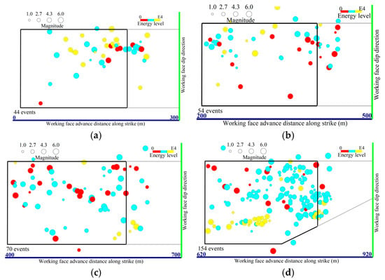
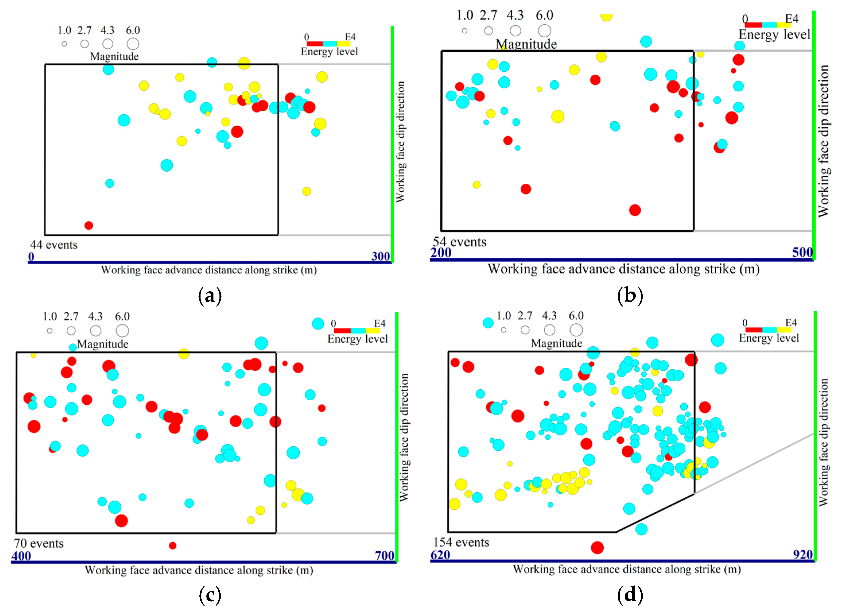
To further characterize the microseismic response under continuous roof-cutting conditions, the planar distribution of microseismic events was analyzed during four representative mining stages, including the single-working-face squaring stage, two-working-face squaring stage, three-working-face squaring stage, and final mining stage, as shown in Figure 24.
Figure 24.
Plan distribution of microseismic events during different mining stages of the 4308 working face: (a) single-working-face squaring stage; (b) two-working-face squaring stage; (c) three-working-face squaring stage; (d) final mining stage.
As shown in Figure 24a, during the single-working-face squaring stage, microseismic events were predominantly concentrated near the working face square position, corresponding to an advanced distance of approximately 210 m. As shown in Figure 24b,c, except for the working face square position, microseismic events exhibited a relatively dispersed distribution, suggesting that fracture activity within the gob-side overburden was more distributed, with no obvious concentration of high-energy fracture events. As shown in Figure 24d, during the final mining stage, as the advance rate decreased and the width of the working face was reduced, microseismic events exhibited a relatively high-frequency and low-energy response, suggesting a more progressive fracture process and distributed energy release under continuous roof-cutting conditions.
Before the working face reached the two-working-face squaring position, relatively high-energy microseismic events were mainly concentrated near the gob side. After entering the three-working-face squaring stage, these events shifted toward the solid coal side. This migration is consistent with the outward adjustment of the main-roof equilibrium arch and the progressive reconstruction of the overburden load-transfer path, which promotes a more coordinated bearing state between the gob and the deep coal mass.
5.3.2. Spatial Distribution Characteristics
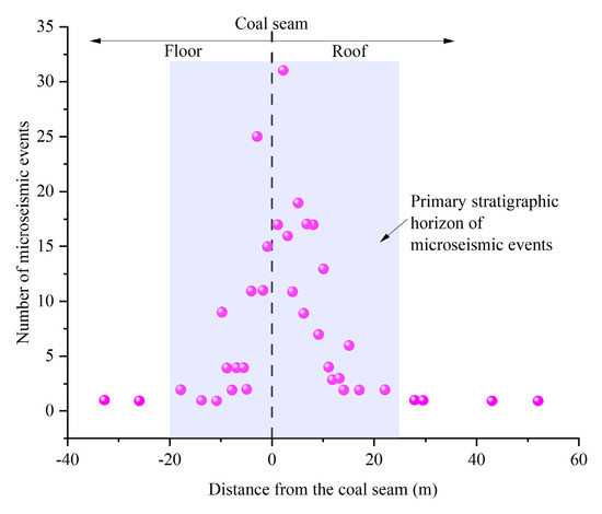
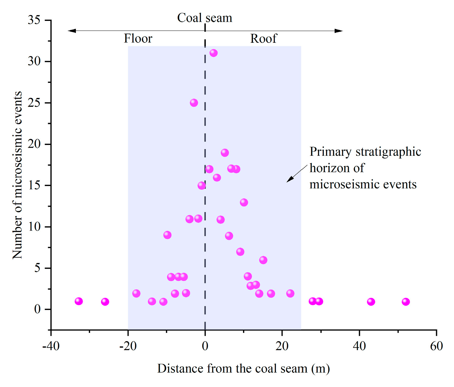
Based on the overburden structural evolution discussed above, the elevation distribution of microseismic events was statistically analyzed to further investigate the influence of continuous roof-cutting on overburden movement at different overburden horizons, as shown in Figure 25.
Figure 25.
Elevation distribution of microseismic events in the working face.
Based on the vertical distribution characteristics of microseismic events, the recorded events were mainly concentrated within a range from approximately 20 m below to 25 m above the coal seam. The larger proportion of roof microseismic events indicates that the dominant fracture activity occurred within the overlying strata. The average roof microseismic development height was approximately 15 m, which was lower than under the coal pillar retention condition. This difference suggests that continuous roof-cutting promoted timely roof failure and load transfer, thereby reducing excessive upward fracture propagation and contributing to the formation of a more stable overburden bearing structure.
Microseismic events were mainly concentrated within the overlying strata above the working face and exhibited an approximately linear distribution pattern. This indicates that roof fracture activity was primarily confined to a limited vertical range rather than developing extensively upward. The stepped spatial distribution of microseismic events reflects the periodic fracture and rotation of roof strata during face advancement, with fracture activity progressively migrating forward and expanding in a cyclic manner.
6. Conclusions
Continuous roof-cutting gob-side entry-retaining provides an effective approach for improving entry stability and mitigating rockburst risks in deep coal mines. However, the mechanism by which continuous roof-cutting reconstructs overburden bearing structure and regulates stress transfer remains insufficiently understood. This study integrates theoretical analysis, numerical simulation, and field microseismic monitoring to investigate overburden structural evolution, stress-transfer mechanism, and rockburst mitigation under continuous roof-cutting conditions. The main conclusions are as follows:
- (1)
- Continuous roof-cutting reshapes the evolution of overburden structures throughout the entire mining process. The overburden evolves from an asymmetric fracture–subsidence structure in the initial working face, to a uniform subsidence structure in the successive working face, and finally to a coordinated subsidence structure in the final working face. This progressive structural evolution promotes coordinated key-strata movement, reduces the development of large-span suspended roof, and improves the overall stability of the overburden system.
- (2)
- Overburden structural evolution alters the mining-induced stress-transfer mechanism. Continuous roof-cutting interrupts the original coal-pillar-controlled load-transfer pathways and promotes the proposed a dual-arch collaborative bearing structure, consisting of an outer main-roof equilibrium arch and an inner compacted gangue arch. Consequently, loads previously concentrated on the coal pillar are redistributed toward the gob and solid coal, promoting stress migration, progressive energy dissipation, and a more uniform stress environment around the retained entry.
- (3)
- Field microseismic observations were generally consistent with the proposed overburden evolution and stress-transfer mechanism. After removal of blasting-induced signals, the monitored working face was dominated by low-energy mining-induced microseismic events, with the maximum recorded event energy remaining below 1 × 10⁴ J. Combined with the numerically observed reduction in abutment stress concentration, these results support the interpretation that continuous roof-cutting promotes progressive roof fracturing and more distributed mining-induced energy release.
The results indicate that an effective roof-cutting operation is the prerequisite for the formation of a stable dual-arch structure. Therefore, roof-cutting should be completed along the entire entry before the extraction of the working face. For hard roofs with poor caving characteristics, pressure-relief measures such as destress blasting and hydraulic fracturing should be adopted to ensure timely roof caving in the gob. For rockburst-prone mines under continuous extraction, microseismic monitoring should be continuously conducted during critical squaring stages to identify abnormal energy concentration and evaluate the effectiveness of roof-cutting pressure relief.
Author Contributions
Conceptualization, M.H. and Z.M.; methodology, Z.M. and Q.Z.; software, H.W.; validation, Z.L., Y.Z. and L.F.; formal analysis, S.Z.; investigation, Z.Y. and L.F.; data curation, Z.M. and H.W.; writing—original draft preparation, H.W.; writing—review and editing, S.Z. and Z.M.; visualization, Y.Z.; supervision, Z.M. and Q.Z.; project administration, Z.M. All authors have read and agreed to the published version of the manuscript.
Funding
This research was funded by Shandong Provincial Natural Science Foundation (No. ZR2024ME257), the National Natural Science Foundation of China (No. 52404155), and the Basic Research Program of Jiangsu (No. BK20231071).
Data Availability Statement
The original contributions presented in this study are included in the article. Further inquiries can be directed to the corresponding authors.
Conflicts of Interest
Author Z.L. was employed by Company: Zaozhuang Mining Group Co., Ltd. Author Y.Z. was employed by Company: Guotun Coal Mine, Shandong Energy Group Luxi Mining Co., Ltd. Author L.F. was employed by Company: Shandong Chengtong Intelligent Equipment Co., Ltd. The remaining authors declare no conflicts of interest.
References
- Wu, W.X.; Gong, F.Q.; Ren, L.; Yu, W.J.; Zhang, Z.X. Dynamic triggering mechanism of rockburst in highly stressed rectangular tunnel under impact load. Tunn. Undergr. Space Technol. 2025, 165, 106908. [Google Scholar] [CrossRef] [Scilit]
- Dai, L.P.; Feng, D.J.; Pan, Y.S.; Wang, A.W.; Ma, Y.; Xiao, Y.H.; Zhang, J.Z. Quantitative principles of dynamic interaction between rock support and surrounding rock in rockburst roadways. Int. J. Min. Sci. Technol. 2025, 35, 41–55. [Google Scholar] [CrossRef] [Scilit]
- Yang, J.; Li, C.J.; Gao, Y.B.; Zhao, Y.; Song, H.X.; Liu, Y.X. Study on failure mechanism and mechanical properties of sliding protection structure in gob-side entry retaining formed by roof-cutting. Rock Mech. Rock Eng. 2025, 58, 6703–6721. [Google Scholar] [CrossRef] [Scilit]
- Yang, D.S.; Guo, Z.B.; Zhao, Y.X.; Gao, J.W.; Li, Y.H.; You, J.L. Geomechanical model test investigation of roof-cutting and roadway maintenance technology under fault structures. Min. Metall. Explor. 2024, 41, 889–908. [Google Scholar] [CrossRef] [Scilit]
- Zheng, R.H.; Hao, B.Y.; Shi, C.Y.; Li, T.X. Study on the ground pressure manifestation patterns of roof-cutting and pressure relief. Appl. Sci. 2025, 15, 6049. [Google Scholar] [CrossRef] [Scilit]
- Cai, M. Rockburst risk control and mitigation in deep mining. Deep Resour. Eng. 2024, 1, 100019. [Google Scholar] [CrossRef] [Scilit]
- Xu, D.; Gao, M.S.; Yu, X. Dynamic response characteristics of roadway surrounding rock and the support system and rock burst prevention technology for coal mines. Energies 2022, 15, 8662. [Google Scholar] [CrossRef] [Scilit]
- Wang, Y.J.; He, M.C.; Wang, Q.; Yang, J.; Wang, J.W.; Liu, H.; Chen, F. Design of equipment system and surrounding rock control for N00 mining method without coal pillar left and roadway excavation. J. China Coal Soc. 2022, 47, 4011–4022. [Google Scholar]
- Zhang, J.; He, M.C.; Yang, G.; Wang, Y.J.; Hou, S.L. N00 method with double-sided roof-cutting for protecting roadways and surface strata. Rock Mech. Rock Eng. 2024, 57, 1629–1651. [Google Scholar] [CrossRef] [Scilit]
- Ni, X. Dynamic evolution characteristics of overburden fractures by non-pillar mining method and conventional mining method. J. Heilongjiang Univ. Sci. Technol. 2026, 36, 548–554. [Google Scholar]
- Zhang, J.; He, M.C.; Shimada, H.; Wang, Y.J.; Hou, S.L.; Liu, B.; Yang, G.; Zhou, P.; Li, H.C.; Wu, X. Similar model study on the principle of balanced mining and overlying strata movement law in shallow and thin coal seam based on n00 mining method. Eng. Fail. Anal. 2023, 152, 107457. [Google Scholar] [CrossRef] [Scilit]
- Sun, R.D.; Zhao, Z.P.; Yang, W.; Li, H.P. Research and application of hydraulic fracturing axial roof-cutting technology for gently inclined hard roof based on abrasive jet. Front. Earth Sci. 2024, 12, 1485210. [Google Scholar] [CrossRef] [Scilit]
- Feng, S.L.; Chen, X.J.; Zhang, R.Q.; Wang, L. Stress regulation and energy dissipation mechanism of roof-cutting in the near-face working area. J. Energy Eng. 2026, 152, 04026054. [Google Scholar] [CrossRef] [Scilit]
- Li, F.; Liu, H.W.; Wang, C.C.; Sun, R.C.; Xiang, G.Y.; Ren, B.R.; Wang, G.H. Stress relief and permeability enhancement with hydraulic fracturing in overlying key strata of deep and soft coal seams. ACS Omega 2023, 8, 12183–12193. [Google Scholar] [CrossRef] [Scilit] [PubMed]
- Xia, Y.X.; Zhang, C.Y.; Du, T.T.; Zhou, J.L.; Sun, R.D.; Lu, C.; Pan, J.F. Process research and application of axial roof-cutting technology of abrasive jet and fracture. J. China Coal Soc. 2024, 49, 36–44. [Google Scholar]
- He, M.C.; Wang, Q.; Wu, Q.Y. Innovation and future of mining rock mechanics. J. Rock Mech. Geotech. Eng. 2021, 13, 1–21. [Google Scholar] [CrossRef] [Scilit]
- Li, H.L.; Liu, H.D.; Liu, C.Y.; Yang, J.X.; Chen, Z.H.; Wu, F.F. Phase field model and numerical simulation study of hydraulic fractures for roadway roof pressure relief. J. China Univ. Min. Technol. 2025, 54, 971–983. [Google Scholar]
- Yang, G.; Yang, X.J.; Huang, R.F.; Kang, X.H.; Zhang, J.; Hou, S.L.; Zhou, P.; He, M.C. Failure mechanism and bulking characteristic of goaf roof in no-pillar mining by roof-cutting technology. Eng. Fail. Anal. 2023, 150, 107320. [Google Scholar] [CrossRef] [Scilit]
- Wang, H.H.; Liu, K.Y.; Shao, Z.J.; Yang, D.S.; Zhang, S.K.; Wang, S.; Guo, Z.B. Mechanism and control strategies of asymmetric floor heave under dynamic pressure in roof-cutting gob-side entry retaining: A case study. Sci. Rep. 2026, 16, 28446. [Google Scholar] [CrossRef] [Scilit] [PubMed]
- Chang, Z.C.; Wang, X.F.; Qin, D.D.; Sun, Y.X.; Yue, Y.P.; Chen, X.Y.; Wang, J.Y. Controlled reconstruction and application research of lateral overlying strata structure in high-gas mines with thick-hard roofs for a fully-mechanized top-caving face. Heliyon 2024, 10, e30705. [Google Scholar] [CrossRef] [Scilit] [PubMed]
- Lv, X.B.; Hu, S.Y.; Nian, J.; Deng, C.S.; Zhao, B.; He, C.; Wang, Y.S.; Zhang, X.T.; Zhang, W. Evolution law of overlying rock fracture field in goaf mining with double-roof-cutting retaining roadway. Sci. Rep. 2025, 15, 4331. [Google Scholar] [CrossRef] [Scilit] [PubMed]
- Zhang, Y.J.; Hu, H.Y.; Liu, Y.S. Study on mining response and control law of deep buried thick and hard roof differential pre-splitting overburden rock. J. Min. Strat. Control Eng. 2026, 8, 261–276. [Google Scholar]
- Liu, J.Z.; Li, D.Y.; Chen, X.J.; Wang, S.; Wang, H.T.; Xu, Y.J. Overburden stress arch elevation effect induced by roof-cutting and destress technique in coal mine longwall panel and its control mechanism to entry surrounding rock. Min. Metall. Explor. 2023, 40, 1237–1252. [Google Scholar] [CrossRef] [Scilit]
- Guo, Z.B.; Wang, H.H.; Ma, Z.M.; Wang, P.F.; Kuai, X.H.; Zhang, X.Z. Research on the transmission of stresses by roof-cutting near gob rocks. Energies 2021, 14, 1237. [Google Scholar] [CrossRef] [Scilit]
- Feng, S.L.; Chen, X.J.; Wang, L.; Li, Y.B. Study on the stress migration law and theoretical model of the stope roof under roof-cutting conditions. Geomech. Geophys. Geo-Energy Geo-Resour. 2026, 12, 19. [Google Scholar] [CrossRef] [Scilit]
- Meng, X.D.; Sui, W.H.; Zhou, C.; Xie, B.L. Unraveling the dynamic failure-stress feedback mechanism in mining overburden through the PIV-DEM synergistic analysis. Int. J. Numer. Anal. Methods Geomech. 2025, 49, 4035–4053. [Google Scholar] [CrossRef] [Scilit]
- Yang, G.Y.; Zhi, B.Y.; Zhang, C.Y.; Liang, S.C.; Xia, Y.X.; Bai, L.; Chen, X.H. Research on the mechanism and effect of sandblasting jet axial roof-cutting technology for rock burst prevention. J. China Coal Soc. 2025, 50, 27−38. [Google Scholar]
- Lu, A.L.; Li, Z.L.; Zhou, C.; Zhou, Y.; He, X.Q.; Song, D.Z.; Li, H.P. Design method of combined cutting parameters for thick-hard roof working face and analysis on rockburst prevention effectiveness. Min. Metall. Explor. 2026, 43, 2669–2682. [Google Scholar] [CrossRef] [Scilit]
- Dong, X.K.; Zhang, J.W.; Liu, J.H.; Zhu, S.T.; Zhang, X.; Zhang, E.H. Failure analysis of rockburst induced by microseismic–stress coupling in deep coal mining with offset open-off cuts under multiple key strata. Eng. Fail. Anal. 2026, 197, 111135. [Google Scholar] [CrossRef] [Scilit]
- Wei, H.; Li, X.X.; Shi, D.Z.; Qin, D.D.; Wang, K. Appearance mechanism and prevention technology of impact energy of roadway floor on additional load. Sci. Rep. 2025, 15, 12882. [Google Scholar] [CrossRef] [Scilit] [PubMed]
- Luo, J.Q.; Yan, S.H.; Yang, T.; Mu, H.Q.; Wei, W.S.; Shen, Y.P.; Mu, H.T. Mechanism of hydraulic fracturing cutting hard basic roof to prevent rockburst. Shock Vib. 2021, 2021, 4032653. [Google Scholar] [CrossRef] [Scilit]
- Hu, B.S.; Wang, T.; Xie, P.S.; Luo, S.H. Prediction of overburden failure on the working face using self-formed roadway mining technology without coal pillars based on microseismic monitoring: A case study. Lithosphere 2024, 3. [Google Scholar] [CrossRef] [Scilit]
- Yang, K.; Zhang, Q.; Zong, T.C.; Cui, P.F.; Jin, Z.S.; Li, H.; Wang, J.Y.; Zhang, R.Y.; Ning, X.Q.; Song, J.H.; et al. Research and application of a new mode of coal mine solid backfill mining and its intelligent key technology. Appl. Sci. 2026, 16, 5264. [Google Scholar] [CrossRef] [Scilit]
- Lai, X.P.; Jia, C.; Cui, F.; Chen, J.Q.; Zhou, Y.P.; Feng, G.G.; Gao, Y.J. Microseismic energy distribution and impact risk analysis of complex heterogeneous spatial evolution of extra-thick layered strata. Sci. Rep. 2022, 12, 10832. [Google Scholar] [CrossRef] [Scilit] [PubMed]
- Guo, W.H.; Liu, H.N.; Jiang, C.R.; Guan, W.M.; Wen, Y.Y.; Cao, A.Y.; Wang, S.W.; Xu, L.Z.; Lv, Z. Study on the mechanisms of hard roof instability and rock burst under faults. Symmetry 2026, 18, 542. [Google Scholar] [CrossRef] [Scilit]
- Tian, H.W.; Jiang, Z.Z.; Ma, Z.Q.; Wen, Z.J.; Zuo, S.J.; Liu, Y.; Li, J.H.; Wang, W.J.; Wang, M.Y.; Jin, Y.C. Microseismic identification and effectiveness assessment of hydraulic-fracturing–induced roof-cutting using an STFT–CNN framework. J. Appl. Geophys. 2026, 246, 106078. [Google Scholar] [CrossRef] [Scilit]








Disclaimer/Publisher’s Note: The statements, opinions and data contained in all publications are solely those of the individual author(s) and contributor(s) and not of MDPI and/or the editor(s). MDPI and/or the editor(s) disclaim responsibility for any injury to people or property resulting from any ideas, methods, instructions or products referred to in the content. |
© 2026 by the authors. Licensee MDPI, Basel, Switzerland. This article is an open access article distributed under the terms and conditions of the Creative Commons Attribution (CC BY) license.