


Abstract
This study presents a comprehensive analysis of the efficiency of periodic metamaterials in attenuating acoustic noise within the audible frequency range of 20 Hz to 20 kHz, in both in-plane (i.e., through the periodicity) and out-of-plane (i.e., through the thickness) directions. This dual assessment is pivotal for understanding the utility of these periodic metamaterials as multi-directional acoustic filters. The present study utilized previously optimized unit cells to construct unidimensional and planar periodic metamaterials, designated as: Optimal Basic-Periodic, Optimal Semi-Periodic, Optimal Tapered-Diverging, and Optimal Tapered-Converging. These unit cells exhibited bandgaps encompassing at least 90% of the audible frequency spectrum. To assess performance, multiple numerical simulations under insertion conditions were conducted, demonstrating that the insertion of metamaterials effectively attenuates at least 54.52 dB of the noise levels within the audible frequency range as sound traverses through both the periodicity and thickness directions, specifically within ranges aligning with bandgaps. Subsequently, a small prototype was fabricated via additive manufacturing, and preliminary experimental validation of through-thickness attenuation was conducted. The measurements showed that the small prototype attenuated within the bandgap ranges and resulted in a 23.74 dB reduction within the audible frequency range.
1. Introduction
Noise pollution due to the vibrations of mechanical systems, prevalent in automotive and aerospace industries, has been an issue of vital concern [1,2]. Examples include the bustling carts used for transporting items within automotive facilities that create considerable noise levels often impacting workers’ well-being [3]. Similarly, noises emanating from different sections of aircraft cabins during flight affect passengers’ overall comfort and safety [4,5,6,7]. These noises have a pronounced negative impact on human health, leading to conditions such as hearing loss, chronic stress, and cardiovascular diseases [1].
Traditional acoustic filters made from mineral wool and fiberglass have been commonly used for soundproofing in the past few decades [8,9,10]. They function by dampening sound waves, leading to a considerable decrease in noise levels. However, the manufacturing of mineral wool and fiberglass has negative implications for both health and the environment. Their production releases harmful particles into the surrounding environment which can cause respiratory diseases when inhaled [11,12,13,14]. Additionally, these materials require high energy consumption during manufacturing and pose disposal challenges due to their non-biodegradable nature [13,15,16].
The emergence of additive manufacturing (AM) offers several advantages, including cleaner, energy-efficient, and more sustainable production technologies, while enabling the creation of highly complex, customized, lightweight, and strong designs with minimal material waste and carbon footprint [17]. It also allows for rapid prototyping, reducing time and cost compared to traditional manufacturing methods. Additionally, AM equipment technology has odor filters to mitigate exposure to harmful emissions and particles. As a result, this technology has made the fabrication of complex geometries including metamaterials usually periodic in nature a great possibility. Moreover, the advancements in AM have opened doors for the exploration of intricate metamaterial designs. Recently, there has been a growing interest in periodic metamaterials as a potential solution for reducing airborne noise and vibration in the automotive and aircraft industries [18]. These materials are engineered with unique properties that differ from those of their raw materials. They have proved promising for applications involving vibration isolation due to their ability to influence elastic waves and their propagation through the presence of elastic bandgaps, which are specific frequency ranges where wave propagation is either prohibited or greatly reduced. Some of the previous research has focused on studying the relationship between these elastic bandgaps and the topology of elastic metamaterials leading to enhancing their designs for vibration isolation applications [19,20,21,22,23,24,25,26,27,28]. Some of these efforts have led to multiple techniques that employ both the conventional optimization methods [29], and machine learning algorithms [30,31,32,33,34].
Building on this success in tuning elastic bandgaps through topological modifications, researchers have explored applying the same concepts to the acoustic spectrum to explore new airborne sound mitigation options. Initial studies primarily focused on the existence and sensitivity of these bandgaps across various design topologies. These studies can be broadly divided into two main categories. The first category encompasses designs characterized by the incorporation of shells and slits [35,36,37,38,39,40,41,42]. Variations in the dimensions, configurations, and spatial distribution of these elements were systematically explored to assess their influences on the acoustic bandgaps’ sensitivity to topological alterations. Results from this category indicated that metamaterials with narrower slit dimensions yielded wider bandgaps that manifest at lower frequency ranges. The second category involves designs predicated on continuous-level surface structures, with a particular emphasis on structures based on Triply Periodic Minimal Surfaces (TPMSs) [43,44,45,46,47,48]. In these designs, the volume fraction was explicitly manipulated to investigate its impact on bandgap topology. Findings suggest that designs with higher volume fraction exhibited broader bandgaps occurring at lower frequency ranges, corroborating observations from the first category whereby an increase in volume fraction (i.e., achieved through narrower slits) corresponded to enhanced bandgap size and a shift to lower frequency ranges.
Following these foundational studies, topology optimization techniques were employed to enhance the acoustic bandgaps. Investigations in this domain can be divided based on two primary objectives. The first objective focused on maximizing the size of the first acoustic bandgap employing both conventional and metaheuristic optimization techniques. Conventional techniques such as Material-Series Field Expansion (MFSE) and Three-Field Floating Projection Topology Optimization (FPTO) approaches were applied to optimize the first acoustic bandgap within two-dimensional density-based design frameworks [49,50,51,52]. Metaheuristic techniques such as Particle Swarm Optimization (PSO) were used to optimize the first acoustic bandgaps in a two-dimensional gear-inspired designs [53]. The second objective focused on maximizing all acoustic bandgaps within a specified frequency range, with bandgap coverage serving as the objective function—a measure of the extent to which bandgaps encompass the desired frequency range. The desired frequency range was the entire audible range (i.e., 20 Hz to 20 kHz). Both shell-slit-based and TPMS-based designs were evaluated using a computationally efficient exhaustive search technique, assessing tens and hundreds of thousands of designs [54,55]. Notably, an optimal unidimensional periodic metamaterial design capable of achieving bandgap coverage of at least 90% across the audible frequency range was identified [54]. These studies underscore the remarkable potential of periodic metamaterials as modern passive acoustic filters for attenuating airborne noise within the audible frequency range.
Other advancements have introduced modern acoustic filters that do not rely on the exhibition of bandgaps and are amenable to fabrication through additive manufacturing techniques. Among these, Sonic Blackholes (SBHs) and acoustic panels have been proposed as modern filters designed to attenuate airborne noise. These filters have demonstrated the capability to manipulate sound waves based on their topological characteristics, akin to the behaviors observed in periodic metamaterials. The design of SBHs is distinguished by a necked geometry, an analogy to the physical appearance of astrophysical black holes. Various SBH configurations have been evaluated, demonstrating their efficacy in attenuating sound waves at specific frequencies [56,57,58,59,60]. For instance, a study which proposed SBH designs featuring both linear and quadratic necking geometries, found that linear-necked SBHs attenuated a broader range of frequencies compared to their quadratic-necked counterparts within the frequency range of 0 Hz to 1.5 kHz [60]. In these SBH filters, attenuation takes place through sound propagation along the neck. Regarding acoustic panels, multiple designs have been explored, with perforated and membrane-type panels being commonly proposed for sound wave attenuation. The geometrical parameters, including size, shape, and pattern of the perforations, were systematically varied to investigate their influence on frequency sensitivity. Examples of perforated panels include those based on hybrid auxetic structures [61], Helmholtz resonators [62], Hilbert fractal inspirations [63], and T/C-shaped resonators [64]. Both hybrid auxetic and Helmholtz-based resonator panels exhibited attenuation across frequency bands ranging from 200 Hz to 1.6 kHz, achieving noise reduction as sound propagated through the thickness. Similarly, T-shaped, C-shaped, and hybrid panels (i.e., combining T- and C-shaped resonators) effectively attenuated noise propagated through the thickness within the frequency ranges of 2.5 to 5.5 kHz and 8.5 to 10 kHz [64]. Panels inspired by Hilbert fractals attenuated noise along their length in the frequency range of 200 Hz to 1.6 kHz [63]. Membrane-type acoustic metamaterials, on the other hand, function by suppressing sound waves through elastic deformations. As an example, a laminated plate-type acoustic panel was proposed to attenuate airborne noise propagated through its thickness within the frequency range of 100 Hz to 800 Hz [65].
These previous studies have elucidated the potential of modern acoustic filters to attenuate audible airborne noise. SBHs and acoustic panels have predominantly been modeled assuming one-dimensional sound propagation [60,61]. However, because in real-world applications, sound propagates in three dimensions, this simplifying assumption can potentially lead to an overestimation of the attenuation efficacy of these filters [66]. Additionally, these filters operate on a singular axis mechanism, either attenuating sound propagation along the length or thickness, but not both [60,64]. In contrast, most periodic metamaterials have been developed based on the premise of three-dimensional sound propagation. Previous research indicated through the numerical computation and experimental measurements of acoustic pressure responses (APRs) that periodic metamaterials effectively attenuate noise at frequency ranges corresponding to the bandgaps as sound propagates along the length (i.e., along the periodicity axis) [35,54,55]. This approach has been used to validate the existence of bandgaps and their relationship with acoustic attenuation in periodic structures. Consequently, the ensuing research should investigate whether periodic metamaterials can attenuate noise propagating through the thickness over frequency ranges that align with the bandgaps. Addressing this question will enhance the understanding of the efficacy of metamaterials as multi-directional acoustic filters for many practical noise attenuation applications. Driven by this inquiry, the present study undertakes a thorough investigation of the acoustic attenuation performance of bandgap-rich unidimensional and planar periodic metamaterials. The selected unit cells constructing these metamaterials were from our previously optimized designs exhibiting bandgaps covering at least 90% of the audible frequency range [54]. The current study also serves as an extension of our previous study through considering planar periodic versions. The present study includes several numerical simulations of the practical noise attenuation scenarios investigating the in-plane (i.e., along the periodicity) and out-plane (i.e., through the thickness) attenuation performance. In addition to conducting numerical simulations, a preliminary fabrication and experimental validation were undertaken. The key contributions are the following:
- (1)
- Investigate the correlation between the in-plane and out-of-plane acoustic attenuation performance of unidimensional and planar periodic metamaterials and their bandgaps by conducting several numerical simulations;
- (2)
- Most importantly, one of the environments considered in these numerical simulations was a surrounding air block encapsulating the metamaterials, enabling the assessment of the efficacy of the metamaterials upon their insertion within a constrained void;
- (3)
- Fabricate a small prototype via additive manufacturing and conduct preliminary experiments demonstrating the out-of-plane attenuation performance and its correlation to bandgaps.
2. Materials and Methods
2.1. Cellular Geometries
The optimal unit cells were identified by selecting the highest coverage of bandgaps across all designs as summarized here. The complete treatment of this subject can be found elsewhere [54]. First, the normalized bandgaps were assessed using FE-Bloch’s Theorem, which was dependent on the unit cell and calculated within a defined region for four different configurations (i.e., along x-axis periodicity which is defined by Γ–X in the 1st Brillouin Zone). Second, the actual bandgaps were determined by varying unit cell sizes (C). Third, optimal designs in each configuration were selected based on their ability to achieve maximum bandgap coverage within the audible frequency range (i.e., 20 Hz to 20 kHz).
Figure 1 and Table 1 display the optimal air unit cell geometries, bandgap-structure, and bandgap coverage [54]. In Figure 1, the grey regions indicate the bandgaps, and the white regions indicate the passbands. This paper chose to represent bandgaps using bandgap-structures rather than the commonly used band-structures (i.e., dispersion curves). For bandgap-dependent studies, such as the one conducted in this paper, bandgap-structures offer a consolidated and more focused plot. This enables the reader to effectively visualize the bandgap details (i.e., its lower and upper bounds). Presenting band-structures is a more effective option for passband- and dual bandgap-passband-dependent studies. It is essential to note that the air unit cells referred to in this work represent the cavity within the solid unit. The analysis revealed that among all optimal unit cells, the Semi-Periodic unit cell had the highest bandgap coverage. Both Basic-Periodic and Tapered-Converging unit cells appear to be almost identical, with Tapered-Converging having a slightly varied neck (see d2/d1 column in Table 1). Consequently, as presented in Figure 1 and documented in Table 1, they have nearly identical bandgap structures and bandgap coverages.
Figure 1.
The bandgap-structure of the optimal designs in x-axis periodicity (i.e., Γ–X) along with their air unit cells presented. The grey regions correspond to the bandgaps while the white ones correspond to the passbands.
Table 1.
Bandgap coverage of the optimal unit cells in the x-axis periodicity (i.e., Γ–X). This table is ranked from the highest to lowest bandgap coverage.
To assess their effectiveness in attenuating sound waves passing within their bandgap frequency range, an excitation and sensing scenario was numerically investigated. The excitation was applied using an external sound source placed at one end of the metamaterial along its tessellation axis (i.e., the longitudinal direction). The metamaterial was excited with sinusoidal acoustic pressure waves of 1 Pa. Three sensing points were distributed across the metamaterial. The results from the Acoustic Pressure Responses (APRs) concluded that unidimensional metamaterial composed from Semi-Periodic unit cells was the most effective one which agreed with the rankings based on the bandgap coverage.
This study employs these unit cells identified in the earlier study [54] to construct unidimensional and planar metamaterials. Subsequently, investigations were conducted to assess the acoustic attenuation performances of these metamaterials in reducing sound levels under various excitation and sensing scenarios. These scenarios will be elaborated upon in subsequent sections.
2.2. Excitation and Sensing Scenarios for the Encapsulation Case
This work investigates the multi-directional acoustic attenuation performance of unidimensional and planar metamaterials constructed from these unit cells. This investigation is performed through conducting excitation and sensing scenarios involving exciting the metamaterials along both their periodicity and thickness. Three excitation and sensing scenarios were considered: one for the unidimensional metamaterial and two for the planar ones. Figure 2 and Figure 3 illustrate these configurations, including the locations of the external sound sources and sensing points. Table 2 and Table 3 provide the coordinates of these points. These coordinates are provided in variable format rather than actual values for generalizability, enabling scalability of these points across different metamaterial dimensions. As shown in Figure 2 and Figure 3, the metamaterials were encapsulated in a block of air. This was mainly performed to ensure identical external sound and sensing points on these metamaterials which were constructed of unit cells with different unit cell sizes (C). The dimensions of the block of air were 500 by 45 by 45 mm for the unidimensional metamaterials and 500 by 500 by 45 mm for the planar ones. The system from this encapsulation is the resultant geometry from both the metamaterial and block of air. The dimensions of the block of air were selected to preserve as much of the metamaterial geometry to have their attenuation performances appear. Although the main objective of this encapsulation was to have identical external and sensing points, investigating such systems brings insights for cases requiring the insertion of the metamaterial in a constrained void.
Figure 2.
The excitation scenario for the unidimensional metamaterials through their thickness. External sound source was positioned at point P and sensing was achieved at points X, Y′, and Z′. Here, LU, WU, and HU, respectively, denote the length, width, and height of the considered block of air surrounding the unidimensional metamaterials.
Figure 3.
The excitation and sensing scenarios for the planar metamaterials. Locations of external sound source (P) for excitations along the x-axis periodicity (A), along the y-axis periodicity (B), and through the thickness (C). (D) Sensing points considered in all the excitation scenarios. Here, Lp, Wp, and Hp, respectively, denote the length, width, and height of the considered block air for planar metamaterials.
Table 2.
The coordinates of the external sound source and sensing points for excitation through the thickness in unidimensional metamaterials. Here, LU, WU, and HU, respectively, denote the length, width, and height of the considered block of air for the unidimensional metamaterials.
Table 3.
The coordinates of the external sound and sensing points for excitation along the periodicity and thickness scenarios in planar metamaterials. Here, Lp, Wp, and Hp, respectively, denote the length, width, and height of the considered block of air for the planar metamaterials.
Figure 2 presents the excitation scenario through the thickness for the unidimensional metamaterials. In this configuration, the external sound source (P) was placed at the bottom centre of the metamaterials. Three sensing points were considered: one at the end along x-axis (denoted as X) and two near the top of the y and z axes, each offset by 75% from the x-axis origin (denoted as Y′ and Z′, respectively).
Figure 3 presents the excitation scenarios for the planar metamaterials along both the periodicity and thickness directions. Figure 3A,B show the external sound sources (P) used for the excitation along the periodicity, positioned at the origins of the x and y axes. The symmetry of the Basic-Periodic, Tapered-Diverging, and Tapered-Converging unit cells results in metamaterials with identical periodicities along x and y axes. Consequently, a single excitation point placed at either origin was sufficient to capture attenuation performance along both periodicity directions. In contrast, the asymmetry of the Semi-Periodic unit cells produces metamaterials with distinct periodicities along x and y axes. Hence, it was required to place separate excitation points at each origin to fully capture the attenuation performance along both periodicities. Figure 3C illustrates the external sound source (P) used for exciting the metamaterials through the thickness. This source was placed at the bottom centre of the metamaterials. Four sensing points were used in both scenarios as illustrated in Figure 3D. Two sensing points were positioned at the ends of the x and y axes (denoted as X and Y). The other two sensing points were positioned at top of the metamaterial along the z axis: one at the midpoint (denoted as Z) and the other offset by 75% from the x-axis origin (denoted as Z′).
Table 4 presents the number of repeated unit cells used to construct the unidimensional and planar metamaterials. The metamaterials were constructed from repeated unit cells based on the dimensions of the air blocks. The dimensions of these air blocks were selected to allow the construction of metamaterials with at least 10 repeated unit cells. This enables bandgaps to dominate attenuation (i.e., greater SPL reductions), since it is generally known that more unit cells yield greater attenuation within bandgap ranges. Admittedly, the current analysis is based on large-scale metamaterials (i.e., composed of many repeated unit cells), and scaling down may show less attenuation in metamaterials that have wider bandgaps but are constructed from fewer unit cells. Such differences are anticipated for designs with comparable bandgaps.
Table 4.
The number of repeated unit cells considered for forming the unidimensional and planar metamaterials in the APR computations.
The excitation for all the scenarios was given through the external sound source (P). Additionally, cases consisting solely of a block of air (i.e., without encapsulating the metamaterial) were analyzed to further investigate the attenuation performance of the metamaterials. Point excitation was used instead of face excitation in this encapsulation case because it serves the study’s purpose with less computational time. Rather than post-processing modeshapes for multiple points in face excitation, modeshapes for a single point were post-processed, which significantly reduces computation time and makes it more practical when comparing these large-scaled (i.e., large dimensions and composed of many repeated unit cells) metamaterials. Following the encapsulation case, full face excitation was applied to the optimal metamaterial, and sound transmission loss (STL) was computed. This is further discussed in Section 3.6.
2.3. Bandgaps Analysis and Acoustic Pressure Response
This subsection details the methodology used to compute both the bandgaps and the acoustic pressure responses (APRs). For both analyses, the solid part is assumed to remain rigid, meaning that the acoustic pressure acting in the air part has negligible influence on causing noticeable deformation of the solid part. This assumption is commonly referred to as impedance mismatch, and the material used to construct the solid part should have a higher acoustic impedance than air. Thus, the physical domain for both analyses is simplified to the air part. The air medium considered to have the density of ρ = 1.2 kg/m3 and the speed of sound of c = 343 m/s.
2.3.1. Bandgap Computation
The previously documented optimal unit cell bandgaps, as determined by Shendy et al. [54], will be applied in this paper. These specific bandgaps are associated with the 1st Brillouin Zone regions [67] and can be seen in Figure 4 within the context of unidimensional and planar metamaterials. In the case of unidimensional metamaterials, only the Γ–X region contains wave numbers that allow for propagation through periodic metamaterial structures. On the other hand, for planar metamaterials, there is a 1st Brillouin zone area consisting of Γ–X–Y–Γ regions as illustrated in Figure 4. Here, Γ–X encompasses wavenumbers allowing propagation along the x-axis periodicity while Y–Γ corresponds to those enabling propagation along the y-axis periodicity. The combined Γ–X–Y–Γ entails a set of wavenumbers permitting wave propagation across all periodicities. Metamaterials constructed from tessellated Basic-Periodic, Tapered-Diverging, and Tapered-Converging unit cells possess unit cell configurations display identical wavenumbers in both directions, attributable to their inherent symmetry. However, when considering metamaterial constructed from tessellated optimal Semi-Periodic unit cells; differences occur between their respective sets of wavenumbers within each direction owing to intentionally designed disparate periodicities.
Figure 4.
The 1st Brillouin zone for the unidimensional and planar metamaterials. (A) Brillouin zone for the unidimensional metamaterials. (B) Brillouin zone for the planar metamaterial composed of tessellated symmetrical unit cells (i.e., Basic-Periodic, Tapered-Diverging, and Tapered-Converging unit cells). (C) Planar metamaterial composed of tessellated asymmetrical unit cells (i.e., Semi-Periodic).
This study aims to calculate the bandgaps of the Semi-Periodic unit cell in the Γ–Y direction, in order to assess the acoustic attenuation performance along the y-axis periodicity. The approach utilizes FE-Bloch’s theorem methodology for determining these bandgaps. This involves solving for the FE-discretized eigen-value problem of the acoustic sound pressure partial differential equation (i.e., Helmholtz equation) [68] within the unit cell by applying Bloch’s theorem. Bloch’s theorem considers the unit cell as the physical domain which captures the bandgaps characteristic of the corresponding periodic structure making the process computationally efficient. This is performed through imposing Periodic Boundary Conditions (P.B.Cs) on the tessellated faces of the unit cell.
In this equation, P is the acoustic pressure while k is the wave number found from the 1st Brillouin zone and ry is the lattice vector along the y-periodicity, ry = 0i + Cj + 0k [69]. Subsequent to considering the P.B.Cs on the tessellated, the FE-discretized eigen-value problem becomes:
−ω(k)2MP + KP = 0
In this equation, M is the mass matrix and K is the stiffness matrix and ω corresponds to the eigenfrequencies. For one design, Equation (2) was solved for each discretized wave number in the 1st Brillouin zone. Twenty-one wave numbers were linearly discretized along the zone of Γ–Y to compute the bandgaps of the Semi-Periodic unit cells along the y-axis periodicity. A commercial FE software package was used (ABAQUS Research 2023). Particularly, Lanczos eigen solver was utilized [70] along with EQUATION function (i.e., used to incorporate the P.B.Cs) to solve Equation (2). AC3D10, ten-node 3D quadratic tetrahedral acoustic elements, were used. Mesh sensitivity analyses showed convergence with the maximum and minimum elements sizing of 3 mm and 0.5 mm, respectively. The mesh sensitivity was based on the maximum relative error of 10−3 in the eigenfrequencies (ω) in 20 Hz to 20 kHz range. Subsequent to these numerical simulations, the eigenfrequencies (ω) were extracted and the band-structure was formed. The band-structure is a plot which presents the eigenfrequencies (ω) over the wave numbers (k). Frequency ranges that are not covered by these eigenfrequencies are referred to as bandgaps. These bandgaps are ranges in which minimal energy is allowed for propagation which leads into significant attenuation when compared to those ranges covered by the eigenfrequencies.
2.3.2. Acoustic Pressure Response Computation
The acoustic attenuation capabilities for modern filters are presented through frequency response functions, commonly referred to as acoustic pressure responses (APRs). The APR plots show the pressure amplitude versus the frequency allowing analysis of the attenuation frequency range. The amplitude in acoustic attenuation is commonly quantified using sound pressure levels and transmission levels (SPLs, STLs) [71,72]. The lower SPL and higher STL over a certain frequency range indicate more attenuation over that range. Both SPL and STL were used to quantify the acoustic pressure for two cases in this work. The SPL was used to quantify the acoustic pressure in a case where the metamaterials are encapsulated in a block of air (see Section 2.2). Here, as mentioned earlier, the physical domain is the coupled geometry comprising the metamaterial and the block of air. The STL was used to quantify the acoustic pressure for a case considering a physical domain comprising only the favorable metamaterial, based on observations from the encapsulation cases. The FE-modal solver was used to compute the acoustic pressure, which is a much faster method than the commonly used FE-direct solver. This enabled the current work to conduct a thorough investigation of large-scale metamaterials by computing acoustic pressure for multiple cases within a realistic timeframe. The FE-modal solver commences with solving the FE-discretized eigen-value problem.
Equation (2) is the version of Equation (3) after applying the Bloch’s theorem. Here, ωn refers to the n-th natural frequency. For simplicity, rigid boundary condition was considered, which is ∇P.n = 0, where ∇ is the gradient and n is the normal vector. Imposing an absorbing boundary condition is necessary if the goal is to predict the actual amplitude of the frequency response for cavities open to air and in far-field situations. Generally, an absorbing boundary condition introduces damping [69], and when comparing its response to that of rigid boundary condition, this damping slightly broadens and suppresses the peak. This feature does not significantly influence the attenuation stemming from bandgaps, which depends on the periodicity of the structure. Because it broadens and dampens the peaks, the absorbing boundary condition may show a wider or slightly shifted attenuation range than the bandgap ranges. Similarly to the treatment of Equation (2), Equation (3) was solved numerically using the same acoustic elements and the LANCZOS solver implemented in ABAQUS. Subsequent to solving Equation (3), both natural frequencies (ωn) and mass normalized acoustic pressure modeshapes (Pm) (i.e., , where I is the identity matrix) were used in the modal solver. The modal solver assumes the response to be a linear combination of the acoustic mode shapes.
P(S) = [Pm][Q(S)]
Equation (4) [54] represents the acoustic pressure response under the assumption of modal solver. Here, Q is the modal acoustic pressure (i.e., a frequency-dependent variable) and S is the discretized frequency domain. The modal acoustic pressure in the frequency domain Q(S) is found algebraically through the following equation.
Equation (5) represents the linear matrix for solving the modal acoustic pressure (Q(S)). Here, Pext refers to the applied external acoustic pressure. Equation (5) shows that the modal acoustic pressure is obtained via the summation of the multiplication of mode shapes and their corresponding external pressure (Pext). This equation was solved for each discretized frequency in the targeted frequency range (i.e., 20 Hz to 20 kHz). Subsequent to this, the acoustic pressure P at the desired points (APRs) are computed using Equation (4).
3. Results and Discussions
3.1. Bandgaps of Semi-Periodic Unit Cell Along Periodic y-Direction
The Semi-Periodic unit cell exhibited a distinct topological feature compared to the other unit cells. This unique feature resulted in a planar metamaterial with different periodicities along the x and y axes, leading to different bandgaps in the two directions. Our previous research focused on obtaining the bandgaps for the Semi-Periodic unit cell along the x-axis, as it primarily studied bandgaps in a unidimensional metamaterial with periodicity along that axis [54]. However, this study investigates the planar metamaterial created from the unit cells and thus aims to assess the bandgaps occurring along the y-axis periodicity of this planar Semi-Periodic metamaterial.
Figure 5 illustrates the bandgap distribution in the y-axis periodicity (i.e., Γ–Y region) of the Semi-Periodic unit cell. The bandgap coverage in this region is found to be 86%, which is lower than that along the x-axis periodicity (i.e., 95.5% as listed in Table 1). A comparison of bandgap frequencies between both axes indicates that the y-axis exhibits narrower and less extensive bandgap coverage compared to the x-axis. However, despite this difference, their bandgap-structures appear similar and cover almost identical frequency ranges, as can be observed in Figure 1 and Figure 5.
Figure 5.
Bandgap-structure of the optimal Semi-Periodic unit cell along y-axis periodicity (i.e., Γ–Y).
3.2. Attenuation Performance of Unidimensional Metamaterials Under Through-Periodicity Excitation for the Encapsulation Case
Our previous study examined the APRs of unidimensional metamaterials constructed of the considered unit cells when excited along the periodicity [54]. Three sensing points were investigated, which will also be considered for the current excitation along the thickness scenario in the unidimensional metamaterials. A construction rule was implemented to create unidimensional metamaterials encapsulated in a block of air, ensuring identical external sound and sensing points as detailed in our previous work. The APRs at these three sensing points were computed using the proposed FE-Modal analysis methodology. Additionally, the APRs of a block of air (i.e., without added metamaterial) at the same three sensing points were calculated to showcase the efficacy of unidimensional metamaterials. The average sound pressure level (SPL) at each location was determined using the centroid method and then used to calculate an overall average SPL by averaging across all considered sensing points. Ranking based on overall average SPLs aligned with bandgap coverage in the x-axis periodicity (i.e., Γ–X direction) revealed that, among other unidimensional metamaterials, Semi-Periodic metamaterial ranked the highest by exhibiting both the lowest overall average SPL and highest bandgap coverage in that direction. The insertion of Semi-Periodic metamaterial had an overall average SPL reduction of 68.63 dB, which is 0.51 dB higher than the Basic-Periodic metamaterial (i.e., an existing topology proposed by Elmadih et al. [36]).
3.3. Attenuation Performance of Unidimensional Metamaterials Under Through-Thickness Excitation for the Encapsulation Case
The present work computed the APRs of unidimensional metamaterials for excitation through the thickness. The computation of the APRs took place at three sensing points, with an external sound source (P) as depicted in Figure 2 [54]. To further explore the noise reduction capabilities of unidimensional metamaterials in attenuating noise in such scenarios, the APRs within a block of air were also examined at the considered sensing points. The amplitudes of the APRs in this and subsequent Section 3.4 and Section 3.5 are quantified as sound pressure levels (SPLs).
In Equation (6), the sound pressure level is the ratio between the acoustic pressure (P) at a sensing location and the reference acoustic pressure Pref = 20 µPa the threshold of human hearing [72]. Subsequently, the average SPL at each sensing point is computed via the centroid method.
Equation (7) presents the centroid method which is the integral of SPL values across the desired frequency range over its size. AdB is the average SPL at a sensing location, this variable will be replaced by the corresponding sensing point (e.g., sensing point X). f is the frequency, while min and max are the subscripts denoting minimum and maximum bounds of the desired frequency range, respectively.
Figure 6A–D display the APRs at sensing point X for the unidimensional metamaterials and block of air while Figures S1–S4 display the APRs at the other sensing points (i.e., Y′ and Z′). In these figures, the corresponding bandgap regions are grey shaded. The average SPL at each sensing point and overall average SPL are presented in Table 5. The APRs of the metamaterials showed that the insertion of the metamaterials in such encapsulation configuration result in attenuation within bandgap ranges. The APRs for the block of air exhibited no attenuation. Additionally, the APRs for the block of air represent the response before inserting the metamaterials and due to rigid boundary conditions imposed, these APRs show closely spaced peaks corresponding to its modes. Table 5 provides rankings of the unidimensional metamaterials from the lowest to the highest overall average SPLs, consistent with the rankings based on the bandgap coverage presented in Table 1. The Semi-Periodic metamaterial achieved an overall average SPL of 2.86 dB, resulting in a 70.42 dB reduction in sound compared to the block of air, and a 1.45 dB reduction compared to the Basic-Periodic metamaterial. All of the metamaterials are comparably effective for noise attenuation when exciting through their thickness.
Figure 6.
The APRs of the unidimensional metamaterials at sensing point X under through-thickness excitation for the encapsulated case. The excitation was performed through giving an external sound source (P) placed at the bottom centre of the metamaterials. (A) Basic-Periodic metamaterial. (B) Semi-Periodic metamaterial. (C) Tapered-Diverging metamaterial. (D) Tapered-Converging metamaterial. The APRs show attenuation in frequency regions corresponding to the bandgaps, demonstrating the efficacy of these unidimensional metamaterials in attenuating noises passing through their thickness.
Table 5.
Average at each sensing point and overall average SPLs obtained from the APRs of the unidimensional metamaterials under through-thickness excitation for the encapsulated case. This table is ranked from the lowest to the highest overall average SPLs.
3.4. Attenuation Performance of Planar Metamaterial Under Through-Periodicity Excitation for the Encapsulation Case
For the excitation through the periodicity scenario, the APRs were computed at the four sensing points while giving at an external sound source (P) located at the periodicity origins of the metamaterial (See Figure 3A,B,D).
Figure 7A–C present the APRs at sensing points X for the Basic-Periodic, Tapered-Diverging, and Tapered-Converging planar metamaterials. While Figures S5, S8 and S9 present the APRs at the other sensing points for these metamaterials. Figure 8 and Figure 9 present the APRs at sensing points X (Panel A) and Y (Panel B) for the Semi-Periodic planar metamaterials when exciting through the x and y axes periodicities, respectively. While Figure S6 and Figure 7 present the APRs at the other sensing points for this metamaterial in these periodicity excitations. Figure 8 and Figure 9 show that these planar metamaterials attenuate differently along x and y axes consistent with their corresponding bandgap-structure. Also, APRs for the metamaterials show significant sound attenuation within the frequency ranges corresponding to the bandgap-structures unlike the block of air with no sound attenuation. Table 6 summarizes the average SPL at each sensing location as well as the overall SPL, sorting planar metamaterials according to their average SPLs. The ranking in Table 6 is different from those in Table 1; this difference is due to the ranking of Table 1 which was based on the bandgap coverage along the x-axis periodicity not both periodicities. While bandgap coverages along both periodicities are identical for the Basic-Periodic, Tapered-Diverging, and Tapered-Converging unit cells, they are different for the Semi-Periodic one (Refer to Figure 1 and Figure 5). Table 6 indicates that the Tapered-Diverging planar metamaterial exhibits a lower overall average SPL compared to all other designs. This is consistent with the fact that the Tapered-Diverging unit cell has the highest bandgap coverage with a value of 94.4% along both the x and y axes periodicities (Refer to Figure 1 and Table 1) than the other unit cells. The insertion of the Tapered-Diverging planar metamaterial achieved a reduction of 67.19 dB, which is 4.42 dB higher than what the planar Basic-Periodic metamaterial could achieve. The Semi-Periodic unit cell shows a reduced bandgap coverage (9.5% reduction) along the y-axis (See Figure 5) compared to its x-axis counterparts and those associated with the Tapered-Diverging unit cells along both periodicities (See Figure 1). This observation is further evident from both average SPLs in Table 6 and attenuated frequency regions in Figure 7, Figure 8, Figure 9 and Figures S5–S9. For instance, for the Semi-Periodic planar metamaterial at sensing point Y, the average SPL is higher by 0.25 dB (excitation through the x-axis periodicity) and 1.06 dB (excitation through the y-axis periodicity) than that for the Tapered-Diverging planar metamaterial. Conversely at sensing point X, the average SPL is lower by 0.47 dB (excitation through the x-axis periodicity) and 1.1 dB (excitation through the y-axis periodicity) than that for the Tapered-Diverging planar metamaterial. It is remarkable that the APRs at the considered sensing points have attenuation regions matching the bandgap-structures along the x and y axes periodicities (See Figure 7, Figure 8 and Figure 9 and compare with Figure 1). This is due to the relative locations of external and sensing points. For instance, sensing point X is placed along x periodicity relative to the external sound point (P) causing the APR to have attenuation regions following the bandgap-structure along x-axis periodicity. Similarly to what was observed for the through-thickness excitation of unidimensional metamaterials, Table 6 also demonstrates that the efficiency of the metamaterials is close, making all of them appealing for excitation along periodicity.
Figure 7.
The APRs of the planar metamaterials constructed from the symmetrical unit cells at sensing point X under through-periodicity excitation scenario for the encapsulated case. The excitation was achieved through an external sound source (P) at the x axis origin. The computed APRs show attenuation in frequency regions matching their corresponding bandgaps. (A) Basic-Periodic metamaterial. (B) Tapered-Diverging metamaterial. (C) Tapered-Converging metamaterial.
Figure 8.
The APRs of the Semi-Periodic planar metamaterials under through-periodicity (along x-axis) excitation scenario for the encapsulated case. The excitation was achieved by an external sound source (P) placed at the x-axis origin. (A) APR at sensing point X. (B) APR at sensing point Y. The computed APRs at both sensing points agree with the corresponding bandgap-structures along both x and y axes periodicities, respectively.
Figure 9.
The APRs of Semi-Periodic planar metamaterials under the through-periodicity excitation (along y-axis) scenario for the y-periodicity case. The excitation was achieved by an external sound source (P) placed at the y-axis origin. (A) APR at sensing point X. (B) APR at sensing point Y. The computed APRs at both sensing points agree with the corresponding bandgap-structures along both x and y axes periodicities, respectively.
Table 6.
Average at each sensing point and overall average SPLs obtained from the APRs of the planar metamaterials under the through-periodicity excitation for the encapsulated case. This table is ranked from the lowest to the highest overall Average SPLs.
3.5. Attenuation Performance of Planar Metamaterials Under Through-Thickness Excitation for the Encapsulation Case
Figure 3C,D show the APRs at the four sensing points for the through-thickness excitation using an external sound source (P) located at the bottom of the metamaterials.
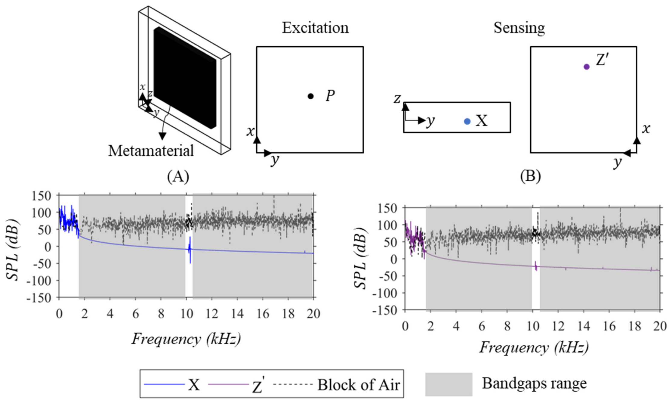
Figure 10, Figure 12 and Figure 13 display the APRs for the Basic-Periodic, Tapered-Diverging, and Tapered-Converging metamaterials at sensing points X and Z′. While Figures S10, S12 and S13 present the APRs for these metamaterials at the other sensing points. Figure 11 presents the APRs for the Semi-Periodic metamaterials at sensing points X, Y, and Z′ and Figure S11 presents the one at sensing point Z. The metamaterials showed attenuation at all sensing points compared to the block of air. APRs at sensing points X, Y, and Z′ showed attenuation in frequency ranges consistent with the corresponding bandgaps. However, in comparison, the APRs at the sensing point Z did show minimal sound attenuation (See Figures S10–S13). Additionally, the APRs at this sensing location did not show an effective attenuation match with the corresponding bandgap-structure, and therefore it was challenging to add grey shaded regions on these plots. This is attributable to the proximity of this sensing point to the external sound source (P) (See Figure 3C,D). This shows that for such an encapsulation configuration, the insertion of metamaterials will effectively attenuate within bandgap ranges at sensing points that are placed at distance from the external source along the periodic axes (i.e., x and y axes). Table 7 presents the average SPL at four sensing points and sorts them based on the overall average SPL. In this excitation scenario, the Tapered-Diverging metamaterial exhibited the lowest overall SPL with value of 10.45 dB which resulted in a reduction of 58.79 dB when compared to the block of air. This reduction is 4.27 dB better than Basic-Periodic metamaterial and 2.51 dB better than the Semi-Periodic (i.e., previous winning unit cell geometry for the unidimensional metamaterials [54]). This observation is aligned with the ones made in planar along-periodicity excitation scenario where Tapered-Diverging metamaterial also exhibited the lowest overall SPLs due to its unit cell having the highest bandgap coverage along both periodicity axes. Therefore, both Table 6 and Table 7 suggest that overall attenuated SPLs correspond to the bandgap coverage along both periodicities. It is notable that while Semi-Periodic showed lower average SPL at X and Z′ sensing points than Tapered-Diverging one, it had a higher average SPL at sensing point Y. This concurs with Semi-Periodic unit cell exhibiting higher bandgap coverage than Tapered-Diverging one along x-axis periodicity but a lower coverage along y-axis periodicity.
Table 7.
Average at each sensing point and overall average SPLs obtained from the APRs of the planar metamaterials under through-thickness excitation for the encapsulated case. This table is ranked from the lowest to the highest overall Average SPLs.
Figure 10.
The APRs of the Basic-Periodic planar metamaterials under through-thickness excitation scenario for the encapsulated case. The excitation was achieved using an external sound source (P) placed at the bottom centre of the metamaterial. (A) The APR at sensing point X. (B) The APR at sensing point Z′. Both computed APRs show attenuation in frequency regions corresponding to the bandgaps, thus verifying the capability of the metamaterial in attenuating noises passing through its thickness.
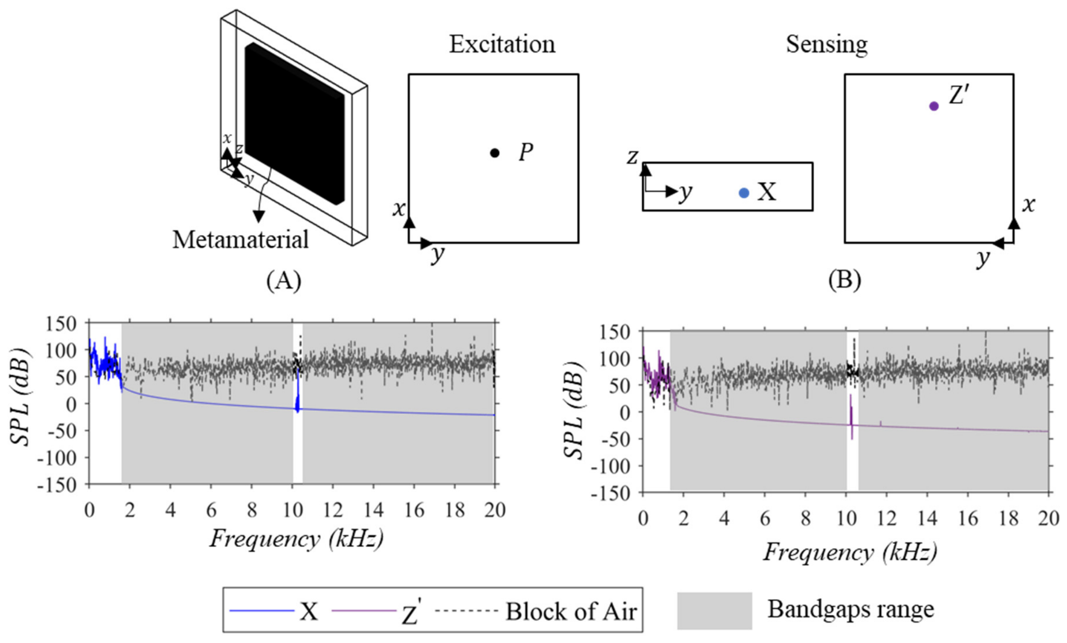
Figure 11.
The APRs of the Semi-Periodic planar metamaterials under the through-thickness excitation scenario for the encapsulated case. The excitation was achieved using an external sound source (P) placed at the bottom centre of the metamaterial. (A) The APR at sensing point X. (B) The APR at sensing point Y. (C) The APR at sensing point Z′. The computed APRs show attenuation in frequency regions corresponding to the bandgaps, thus verifying the capability of the metamaterial in attenuating noises passing through its thickness.
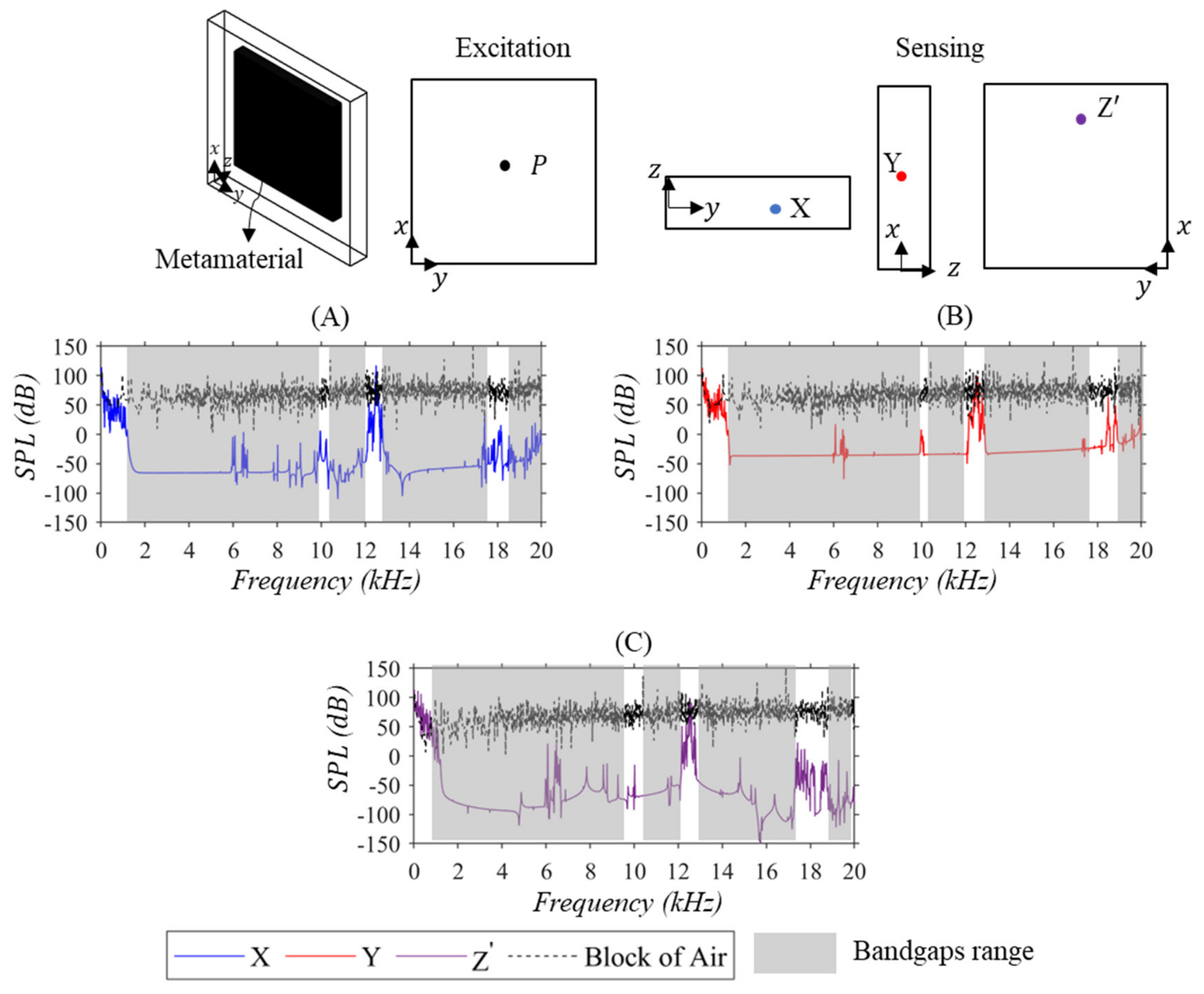
Figure 12.
The APRs of the Tapered-Diverging planar metamaterials under through-thickness excitation scenario for the encapsulated case. The excitation was achieved using an external sound source (P) placed at the bottom centre of the metamaterial. (A) The APR at sensing point X. (B) The APR at sensing point Z′. Both computed APRs show attenuation in frequency region corresponding to the bandgaps, thus verifying the capability of the metamaterial in attenuating noises passing through its thickness.
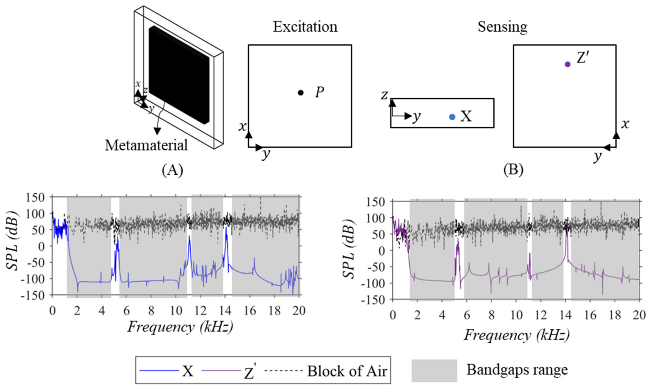
Figure 13.
The APRs of the Tapered-Converging planar metamaterials under the through-thickness excitation scenario for the encapsulated case. The excitation was achieved using an external sound source (P) placed at the bottom centre of the metamaterial. (A) The APR at sensing point X. (B) The APR at sensing point Z′. Both computed APRs show attenuation in frequency regions corresponding to the bandgaps, thus verifying the capability of the metamaterial in attenuating noises passing through their thickness.
3.6. The Sound Transmission Loss for Optimal Metamaterials
The sound transmission loss (STL) for the tapered-diverging unidimensional and planar metamaterials was computed. These STL computations were conducted to further demonstrate the efficacy of the optimal metamaterials. The STL evaluates the acoustic attenuation performance of a structure. The STL is computed through the following:
where:
Equation (8) delineates the equation utilized to calculate the STL, wherein Wi and Wt represent the incident and transmitted acoustic powers, respectively. Equations (9) and (10) elucidate the correlation between the incident and transmitted powers and their respective acoustic pressures, denoted as Pi and Pt, which indicate the incident and transmitted acoustic pressures, respectively. Here, dA refers to the area over which incident and transmitted acoustic pressures are applied.
The unidimensional and planar metamaterials examined in this study were constructed by a total of twelve Tapered-Diverging unit cells. These metamaterials are the ones considered in the above-discussed APRs. However, unlike the APRs investigations, which considered a domain comprising metamaterials encapsulated in a block of air, here, a domain solely comprising metamaterial was considered. Figure 14A–C illustrate the considered domain (i.e., air part of the metamaterial) along with the conducted scenarios. It is crucial to emphasize that the number of repeated unit cells depicted in Figure 14A–C (i.e., appearing to be consisting of four unit cells) does not reflect on the actual number considered (i.e., twelve unit cells) in the STL computations. This was only performed for providing clear visual illustrations on the domains and scenarios considered. Three scenarios were investigated to compute the STL of the optimal metamaterials, as depicted in Figure 14A–C. The first scenario was employed to calculate the STL corresponding to the attenuation performance as noise propagates through the periodicity of the unidimensional metamaterial, as shown in Figure 14A. While Figure 14B,C illustrate the second and third scenarios, in which STLs were determined as the noise propagated through the periodicity and thickness of the planar metamaterial. The excitation source (i.e., incident acoustic pressure Pi in Equation (9)) had a magnitude of Pi = 1 Pa and was applied on one of the metamaterials’ faces and over discretized frequencies in the range spanning from 20 Hz to 20 kHz, with frequency spacing of 10 Hz. For all of the STL scenarios, the excitation was applied on the face rather than on a point as considered in the APRs scenarios. These types of excitation scenarios demonstrate another real-life practical application where the noisy part is fully exciting a surface of the metamaterial (e.g., the bottom surface of the metamaterial in Figure 14C). The acoustic pressures on the sensed faces (i.e., transmitted acoustic pressure Pt in Equation (10)) were considered, unlike the APRs investigations which evaluated the acoustic pressure pertaining to a single point. The STLs were calculated numerically, using the FE-Modal solver to evaluate the acoustic pressures at the sensed faces via Equation (3) and subsequently applying Equations 8 to 10 for computing the STLs.
Figure 14.
The three scenarios considered for computing the STLs. (A) Excitation through the periodicity for the unidimensional metamaterial. (B) Excitation through the periodicity for the planar metamaterial. (C) Excitation through the thickness for the planar metamaterials.
Figure 15A–C present the STLs for the three scenarios considered. All the STLs exhibit increased transmission loss (i.e., attenuation) within frequency ranges corresponding to the bandgap frequency ranges (refer to Figure 1). A comparison between Figure 15B,C reveals that the planar metamaterial achieved greater noise attenuation along the periodicity than through the thickness as expected from the more repeated unit cells along the periodicity directions. Additionally, the negative STL values in both Figure 15B,C correspond to the resonances (i.e., natural frequencies) of the metamaterial which falls under the passband ranges in the corresponding bandgap-structure that are displayed as white ranges in Figure 1.
Figure 15.
The computed STLs of the Tapered-Diverging unidimensional and planar metamaterials for excitation along the periodicity and thickness scenarios. (A) STL of the unidimensional metamaterial for excitation through periodicity. (B) STL of the planar metamaterial for excitation through periodicity. (C) STL of the planar metamaterial for excitation through thickness. These panels show attenuation (i.e., high STL values) within frequency ranges corresponding to the bandgap-structure. Notably, excitation along the periodicity results in greater attenuation than excitation through the thickness, which is expected due to the higher number of unit cells along the periodicity direction.
Comparing Figure 15C with Figure S12B shows that the metamaterials, as a sole domain, can attenuate noise through the thickness within bandgap ranges. However, once coupled with another domain, it is unable to do so. This conclusion may aid in understanding the operability condition of the metamaterials.
3.7. Preliminary Fabrication and Experimental Validation
This section details our preliminary efforts in fabricating and experimentally validating the acoustic attenuation performance of these metamaterial designs. A planar metamaterial fabricated from a 2-by-2 lattice of Tapered-Diverging unit cells was investigated. The metamaterial was additively manufactured via material jetting utilizing a J750 Polyjet 3D printer (Stratasys, Minnetonka, MN, USA). Material jetting is known for its superiority in fabricating intricate structures with a tight tolerance [73]. Briefly, in this method, the printer deposits liquid photocurable resins through the print heads which is later solidified by the attached UV lamps. The selected printer consists of multiple print heads which allows for depositing different resin, thus rendering multi-material structure feasible. This feature was advantageous for this work since the structure and supports were selected to be composed of different materials. VeroClear was the resin used to fabricate the metamaterial. This resin results in a stiff material with the Elastic Modulus of E = 2.5 GPa and density of ρ = 1180 kg/m3 which yield in much higher acoustic impedance than of air, thus satisfying the assumed impedance mismatch. On the other hand, the support was made of a soft (i.e., gel-like) resin named SUP706. Subsequent to printing, the supports were removed through a series of solution soaking (i.e., caustic soda (sodium hydroxide) and sodium metasilicate (Na2SiO3)) and water-jetting. Figure 16 shows the fabricated metamaterial considered for this preliminary investigation.
Figure 16.
The fabricated metamaterial constructed from a 2-by-2 lattice of optimal Tapered-Diverging unit cells.
The preliminary experimental validation was conducted through the considered case study presented in Figure 17. Figure 17A shows the setup and instrumentation used. A computer (Lenovo P52) was used to generate the electrical signal via MATLAB (MATLAB, R2021a, Mathworks, MA, USA) Data Acquisition System (DAQ) toolbox and later converted the recorded sound pressure signal from time to frequency domain using Fast Fourier Transform (FFT) software (BK Connect, 2018.1, Bruel and Kjaer, Naerum, Denmark). A microphone–preamplifier combination (Bruel and Kjaer Type 4189 1/2” Free-Field pre-polarized microphone with preamplifier Bruel and Kjaer Type 2671) was used to record the sound pressure signals. A power audio amplifier (Rolls RA235) was utilized to amplify the electrical signal from the computer to drive a speaker (Dayton Audio PC68-4). A portable DAQ (Bruel and Kjaer Type 2270 Handheld Analyzer) was used to capture the recorded sound pressure signal from the microphone.
Figure 17.
The experimental setup and recording configurations considered. (A) The setup and instrumentation used. (B) The first recording configuration referred to as “Without Meta”, where no metamaterial is placed between the speaker and microphone. (C) The second recording configuration referred to as “With Meta” which placed the metamaterial atop the speaker. The first recording configuration was conducted to compare its measured APR with those obtained in the second one, in order to validate the attenuation performance of the fabricated metamaterial.
The microphone (Bruel and Kjaer Type 4189 1/2” Free-Field pre-polarized microphone with preamplifier Bruel and Kjaer Type 2671) was calibrated using a sound calibrator (Bruel and Kjaer Type 4231), yielding a measured sensitivity of 51.16 mV/Pa. The speaker (Dayton Audio PC68-4) has a frequency range of 20 Hz to 20 kHz. The portable DAQ (Bruel and Kjaer Type 2270 Handheld Analyzer) has a sampling frequency of 48 kHz. 3200 linearly spaced frequency bins were used in the FFT analysis. Each measurement was recorded on three occasions, and the average was documented. For floor noise, because the test was conducted in a laboratory environment, low-frequency noise (i.e., below 100 Hz) from heating, ventilation, and air conditioning (HVAC) systems (e.g., fans and air conditioners) was significant (roughly around 10 dB). This does not contaminate the SPL within the bandgap ranges, which start at 784 Hz.
Figure 17B,C, respectively, show the block of air control and metamaterial stimulation and recording configuration by placing the microphone at a distance from the speaker. In this configuration, the metamaterial was placed atop the speaker to investigate the acoustic attenuation efficacy of the metamaterial as noise passes through its thickness. The first and second configurations are referred to as “Without Meta” and “With Meta”, respectively, in the following. Similar configurations were adopted to experimentally investigate the attenuation performance of a three-dimensional periodic metamaterial [35]. The stimulus signal was a chirp signal ranging from 20 Hz to 20 kHz. For the second configuration, the metamaterial was specifically placed atop the speaker’s frame, which prevents it from loading the speaker’s diaphragm. Consequently, this consideration is expected to enable equal electrical loading for both the first and second configurations, yielding almost identical sound signals.
The selection of a 2-by-2 lattice of unit cells was based on our numerical findings presented in Figure 18A (see the inset in Figure 18A for the excitation and configuration), which showed APR that exhibit attenuation aligning with the bandgap regions. This observation is surprising since from a geometric standpoint, a 2-by-2 lattice of unit cells is not periodic enough to ensure that at least one unit cell has all its boundaries interfacing with those of the adjacent unit cells, which is required for the Periodic Boundary Conditions assumption to be valid. In the meantime, since the 2-by-2 lattice of unit cells shows such an attenuation range, it serves as a good option for experimental validation at a preliminary level. Nevertheless, future work should seek a physical explanation for this observation. Specifically, it seems that for some unit cell designs, a feature of identical bandgaps for decoupled and coupled connectivity modes exists. This means that, for such designs, the bandgaps of a unit cell (i.e., decoupled connectivity mode, which could be one unit cell or a finite structure consisted of a set of disconnected unit cells) are identical to those in a set of connected unit cells (i.e., coupled connectivity mode, a finite structure consisted of a set of unit cells fully connected to each other). That would be an interesting case, where some unit cell designs share identical attenuation features in the two connectivity modes. Figure 18B shows the measured APRs for both configurations. This figure shows the metamaterial significantly attenuated (~23.74 Db in computed via subtracting the overall averages of both configurations, the overall averages were computed via the centroid method presented in Equation (7)) the broadband chirp signal in frequency ranges that are in good agreement with the corresponding bandgap-structure shown in Figure 1.
Figure 18.
(A) Numerical computed APR of the 2-by-2 lattice of unit cells for the excitation and sensing configuration illustrated in the inset. (B) The experimental measured APRs for both recording configurations. The grey shades represent the bandgaps region, and they align well with the attenuation regions in A and B (blue line in A and red line B).
Qualitative comparison of Figure 18A,B shows that the frequency characteristics, specifically the bandgaps, contributed to attenuation. Hypothetically, if bandgaps did not exist within these cavities and the cavities transmitted the speaker’s generated sound with no losses and amplification (i.e., due to resonance), the only attenuation mechanism would be the reduced surface area. Theoretically, using Equation (8), this would lead to a 21 dB reduction (by taking the logarithmic ratio of the speaker’s outer surface area to the cavities’ surface area). This is 2.69 dB lower than the reduction realized by the prototype in the conducted test within the audible frequency range. To illustrate the bandgap effect more precisely, the prototype achieved an average SPL reduction of 36 dB within the third bandgap range (i.e., from 11 kHz to 14 kHz), which is 15 dB higher than the reduction achieved with the reduced surface area (i.e., 21 dB). One could say that the unstructured counterpart (i.e., a solid block made of the same material) would lead to better attenuation. While this is true, the objective of our previous [54] and current work is to optimize porous metamaterial such that it could have comparable attenuation behavior to its unstructured counterparts. The metamaterial is 9% lighter than its unstructured counterparts and is porous. This may open doors to further development of metamaterials for applications requiring weight reduction and proper ventilation.
The presented preliminary experimental data were the first step toward validation. These measurements were not performed in an ideal acoustic environment with reflections from the surrounding walls. These unwanted reflections may be the reason for the narrow-spaced peaks in Figure 18B, making the measurement noisy. Additionally, the metamaterial prototype was small and consisted of only a 2-by-2 lattice. Although measurements showed a good match with the bandgap-structure, a larger lattice should be investigated to further verify agreement. Our future studies will include comprehensive experimental validations employing larger metamaterial prototypes.
4. Conclusions
This study has demonstrated the in-plane and out-of-plane acoustic attenuation performance of bandgap-rich unidimensional and planar periodic metamaterials through thorough numerical simulations and preliminary experimental validation. Most importantly, through multiple numerical simulations, the study has provided insights into the operational conditions of metamaterials for attenuating noise through their periodicity and thickness within bandgap ranges. The results showed the following:
- The insertion of unidimensional metamaterials for a through-thickness point excitation scenario in the encapsulated case resulted in at least 69 dB SPL reduction. In this case, the considered unidimensional metamaterials performed comparably, with the Semi-Periodic design yielding slightly higher SPL reduction due to its higher bandgap coverage;
- The insertion of the planar metamaterials in the encapsulated case resulted in at least 63.77 dB and 54.52 dB SPL reductions for the through-periodicity and through-thickness point excitation scenarios, respectively. In both scenarios, attenuation aligned with bandgap ranges was observed at sensing points located along the x and y axes at distances from the external point source. Similarly to those observed for unidimensional metamaterials, the considered planar metamaterials exhibited comparable SPL reductions. However, for planar configurations, the Tapered-Diverging design yielded higher reductions due to its higher bandgap coverage along the x and y axes;
- STLs were computed for unidimensional and planar Tapered-Diverging metamaterials, considering through-periodicity and -thickness face excitation scenarios. The computed STLs showed that the metamaterials attenuate noise within bandgap ranges for both through-periodicity and -thickness face excitation scenarios. From these findings, it is suggested that the planar metamaterials attenuate noise through their thickness when not interfering with other domains (e.g., a block of air, as observed in the results of the encapsulated case);
- We conducted a preliminary experimental validation of a small prototype constructed from a 2-by-2 lattice of Tapered-Diverging unit cells. Both numerical and measured APRs showed that the prototype attenuated noise within the bandgap ranges, which was an interesting observation to document. Nevertheless, future work should include a physical explanation behind this observation. The measured APRs served as our first step toward experimentally validating our optimized metamaterial designs.
This work provided practical insights into the use of periodic metamaterials as a multi-directional modern acoustic filter.
Supplementary Materials
The following supporting information can be downloaded at: https://www.mdpi.com/article/10.3390/app16199654/s1, The Supplementary Material provides the APRs for several other sensing points in addition to the ones considered in the unidimensional and planar excitation scenarios for the encapsulated case.
Author Contributions
Conceptualization, M.S., A.S. and N.M.; methodology, M.S., A.S. and N.M.; software, M.S.; validation, M.S.; formal analysis, M.S.; investigation, M.S., A.S. and N.M.; resources, A.S. and N.M.; data curation, M.S.; writing—original draft preparation, M.S.; writing—review and editing, N.M. and A.S.; visualization, M.S.; supervision, A.S. and N.M.; project administration, A.S. and N.M.; funding acquisition, A.S. and N.M. All authors have read and agreed to the published version of the manuscript.
Funding
This work was supported by the Natural Sciences and Engineering Research Council of Canada, the Canada Foundation for Innovation, Ontario Research fund and the Federal Economic Development Agency for Southern Ontario (FedDev Ontario) in the Waterloo Institute for Sustainable Aeronautics at the University of Waterloo.
Institutional Review Board Statement
Not applicable.
Informed Consent Statement
Not applicable.
Data Availability Statement
The data that support the findings of this study are available from the corresponding author upon reasonable request.
Acknowledgments
This work was partially conducted using the High-Performance Computing infrastructures of Digital Alliance of Canada.
Conflicts of Interest
The authors declare no conflicts of interest.
References
- Dalton, B.H.; Behm, D.G. Effects of Noise and Music on Human and Task Performance: A Systematic Review. Occup. Ergon. 2007, 7, 143–152. [Google Scholar] [CrossRef] [Scilit]
- Liu, F.; Jiang, S.; Kang, J.; Wu, Y.; Yang, D.; Meng, Q.; Wang, C. On the Definition of Noise. Humanit. Soc. Sci. Commun. 2022, 9, 406. [Google Scholar] [CrossRef] [Scilit] [PubMed]
- Achieving Noise Reduction in Industrial Carts. Available online: https://www.shoplinco.com/blog/whispering-wheels-achieving-noise-reduction-in-industrial-carts/?srsltid=AfmBOorL0hp3U1yDc-1bvkyGxBVyYZtqpYdQtj1HrvmkVCvltbWuRq8d (accessed on 30 October 2024).
- Charakida, M.; Deanfield, J.E. Nighttime Aircraft Noise Exposure: Flying towards Arterial Disease. Eur. Heart J. 2013, 34, 3472–3474. [Google Scholar] [CrossRef] [Scilit] [PubMed]
- Stansfeld, S.A.; Berglund, B.; Clark, C.; Lopez-Barrio, I.; Fischer, P.; Öhrström, E.; Haines, M.M.; Head, J.; Hygge, S.; van Kamp, I.; et al. Aircraft and Road Traffic Noise and Children’s Cognition and Health: A Cross-National Study. Lancet 2005, 365, 1942–1949. [Google Scholar] [CrossRef] [Scilit] [PubMed]
- Bullmore, A.J.; Nelson, P.A.; Elliot, S.J. Theoretical Studies of The Active Control of Propeller-Induced Cabin Noise. J. Sound Vib. 1990, 140, 191–217. [Google Scholar] [CrossRef] [Scilit]
- Ozcan, H.K.; Nemlioglu, S. In-Cabin Noise Levels during Commercial Aircraft Flights. Can. Acoust. 2006, 34, 31–35. [Google Scholar]
- Uris, A.; Llopis, A.; Llinares, J. Effect of the Rockwool Bulk Density on the Airborne Sound Insulation of Lightweight Double Walls. Appl. Acoust. 1999, 58, 327–331. [Google Scholar] [CrossRef] [Scilit]
- Yang, Y.; Li, B.; Chen, Z.; Sui, N.; Chen, Z.; Xu, T.; Li, Y.; Fu, R.; Jing, Y. Sound Insulation of Multi-Layer Glass-Fiber Felts: Role of Morphology. Text. Res. J. 2017, 87, 261–269. [Google Scholar] [CrossRef] [Scilit]
- Padhye, R.; Nayak, R. Textile Science and Clothing Technology Acoustic Textiles; Springer: Berlin/Heidelberg, Germany, 2016. [Google Scholar]
- Kupczewska-Dobecka, M.; Konieczko, K.; Czerczak, S. Occupational Risk Resulting from Exposure to Mineral Wool When Installing Insulation in Buildings. Int. J. Occup. Med. Environ. Health 2020, 33, 757–769. [Google Scholar] [CrossRef] [Scilit] [PubMed]
- Domokos Hancu, B.; Pop, M. Assessment of Health Effects Related to Fiber Glass Exposure in Fiber Glass Workers: Exhaled Biomarkers ECO, FEno And Their Usefulness in the Occuptional Environment Testing. Pulmonol. Clujul Med. 2013, 86, 114. [Google Scholar]
- Yilmaz, N.D. Acoustic Properties of Biodegradable Nonwovens; North Carolina State University: Raleigh, NC, USA, 2009. [Google Scholar]
- Asdrubali, F.; Schiavoni, S.; Horoshenkov, K.V. A Review of Sustainable Materials for Acoustic Applications. Build. Acoust. 2012, 19, 283–312. [Google Scholar] [CrossRef] [Scilit]
- Consultants, P. Eco-Indicator 99 Manual for Designers; Ministry of Housing, Spatial Planning and the Environment: The Hague, The Netherlands, 2000. [Google Scholar]
- Yilmaz, N. Agro-Residual Fibers as Potential Reinforcement Elements for Biocomposites. In Lignocellulosic Polymer Composites: Processing, Characterization, and Properties; Pamukkale University: Denizli, Turkey, 2014; pp. 231–270. ISBN 9781118773574. [Google Scholar]
- Shuaib, M.; Haleem, A.; Kumar, S.; Javaid, M. Impact of 3D Printing on the Environment: A Literature-Based Study. Sustain. Oper. Comput. 2021, 2, 57–63. [Google Scholar] [CrossRef] [Scilit]
- Khalid, M.Y.; Arif, Z.U.; Tariq, A.; Hossain, M.; Umer, R.; Bodaghi, M. 3D Printing of Active Mechanical Metamaterials: A Critical Review. Mater. Des. 2024, 246, 113305. [Google Scholar] [CrossRef] [Scilit]
- Phani, A.S.; Woodhouse, J.; Fleck, N.A. Wave Propagation in Two-Dimensional Periodic Lattices. J. Acoust. Soc. Am. 2006, 119, 1995–2005. [Google Scholar] [CrossRef] [Scilit] [PubMed]
- Alkhader, M.; Iyer, S.; Shi, W.; Venkatesh, T.A. Low Frequency Acoustic Characteristics of Periodic Honeycomb Cellular Cores: The Effect of Relative Density and Strain Fields. Compos. Struct. 2015, 133, 77–84. [Google Scholar] [CrossRef] [Scilit]
- Bayat, A.; Gaitanaros, S. Elastic Wave Propagation in Open-Cell Foams. J. Appl. Mech. Trans. ASME 2019, 86, 051008. [Google Scholar] [CrossRef] [Scilit]
- Spadoni, A.; Ruzzene, M.; Gonella, S.; Scarpa, F. Phononic Properties of Hexagonal Chiral Lattices. Wave Motion 2009, 46, 435–450. [Google Scholar] [CrossRef] [Scilit]
- Wang, P.; Casadei, F.; Kang, S.H.; Bertoldi, K. Locally Resonant Band Gaps in Periodic Beam Lattices by Tuning Connectivity. Phys. Rev. B Condens. Matter Mater. Phys. 2015, 91, 020103. [Google Scholar] [CrossRef] [Scilit]
- Zhao, P.; Zhang, K.; Deng, Z. Elastic Wave Propagation in Lattice Metamaterials with Koch Fractal. Acta Mech. Solida Sin. 2020, 33, 600–611. [Google Scholar] [CrossRef] [Scilit]
- Zhao, P.; Zhang, K.; Zhao, C.; Deng, Z. Mechanism of Band Gaps in Self-Similar Triangular Lattice with Koch Fractal. J. Vib. Acoust. 2022, 144, 031009. [Google Scholar] [CrossRef] [Scilit]
- Zhao, P.; Zhang, K.; Zhao, C.; Qi, L.; Deng, Z. In-Plane Wave Propagation Analysis for Waveguide Design of Hexagonal Lattice with Koch Snowflake. Int. J. Mech. Sci. 2021, 209, 106724. [Google Scholar] [CrossRef] [Scilit]
- Paul, D.; Jayaprakash, K.R. Parametric Analysis of Bandgaps in a General Metachiral Lattice Using Discrete Dynamical Analysis. Wave Motion 2024, 128, 103289. [Google Scholar] [CrossRef] [Scilit]
- Yang, F.; Yang, J.S.; Wang, Y.; Li, S.; Chen, Y.Y. Low Frequency Bandgap Characteristics of a 3D Chiral Acoustic Metamaterial Structure. Wave Motion 2024, 128, 103303. [Google Scholar] [CrossRef] [Scilit]
- Choi, M.J.; Oh, M.H.; Koo, B.; Cho, S. Optimal Design of Lattice Structures for Controllable Extremal Band Gaps. Sci. Rep. 2019, 9, 9976. [Google Scholar] [CrossRef] [Scilit] [PubMed]
- Shendy, M.; Alkhader, M.; Abu-Nabah, B.A.; Jaradat, M.A.; Venkatesh, T.A. Machine Learning Assisted Approach to Design Lattice Materials with Prescribed Band Gap Characteristics. Eur. J. Mech. A/Solids 2023, 102, 105125. [Google Scholar] [CrossRef] [Scilit]
- Shendy, M.; Jaradat, M.A.; Alkhader, M.; Abu-Nabah, B.A.; Venkatesh, T.A. Hybrid Intelligent Framework for Designing Band Gap-Rich 2D Metamaterials. Int. J. Solids Struct. 2024, 304, 113053. [Google Scholar] [CrossRef] [Scilit]
- Wang, Z.; Xian, W.; Baccouche, M.R.; Lanzerath, H.; Li, Y.; Xu, H. Design of Phononic Bandgap Metamaterials Based on Gaussian Mixture Beta Variational Autoencoder and Iterative Model Updating. J. Mech. Des. 2022, 144, 041705. [Google Scholar] [CrossRef] [Scilit]
- Wang, W.; Cheney, W.; Amirkhizi, A.V. Generative Design of Graded Metamaterial Arrays for Dynamic Response Modulation. Mater. Des. 2024, 237, 112550. [Google Scholar] [CrossRef] [Scilit]
- Ha, C.S.; Yao, D.; Xu, Z.; Liu, C.; Liu, H.; Elkins, D.; Kile, M.; Deshpande, V.; Kong, Z.; Bauchy, M.; et al. Rapid Inverse Design of Metamaterials Based on Prescribed Mechanical Behavior through Machine Learning. Nat. Commun. 2023, 14, 5765. [Google Scholar] [CrossRef] [Scilit] [PubMed]
- Bilal, O.R.; Ballagi, D.; Daraio, C. Architected Lattices for Simultaneous Broadband Attenuation of Airborne Sound and Mechanical Vibrations in All Directions. Phys. Rev. Appl. 2018, 10, 054060. [Google Scholar] [CrossRef] [Scilit]
- Elmadih, W.; Chronopoulos, D.; Zhu, J. Metamaterials for Simultaneous Acoustic and Elastic Bandgaps. Sci. Rep. 2021, 11, 14635. [Google Scholar] [CrossRef] [Scilit] [PubMed]
- Jiang, H.; Chen, Y. Lightweight Architected Hollow Sphere Foams for Simultaneous Noise and Vibration Control. J. Phys. D Appl. Phys. 2019, 52, 325303. [Google Scholar] [CrossRef] [Scilit]
- Aravantinos-Zafiris, N.; Kanistras, N.; Sigalas, M.M. Acoustoelastic Phononic Metamaterial for Isolation of Sound and Vibrations. J. Appl. Phys. 2021, 129, 105108. [Google Scholar] [CrossRef] [Scilit]
- Li, G.; Chen, Y.; Chen, W.; Liu, J.; He, H. Local Resonance—Helmholtz Lattices with Simultaneous Solid-Borne Elastic Waves and Air-Borne Sound Waves Attenuation Performance. Appl. Acoust. 2022, 186, 108450. [Google Scholar] [CrossRef] [Scilit]
- Xia, B.; Li, L.; Liu, J.; Yu, D. Acoustic Metamaterial with Fractal Coiling Up Space for Sound Blocking in a Deep Subwavelength Scale. J. Vib. Acoust. 2018, 140, 011011. [Google Scholar] [CrossRef] [Scilit]
- Li, J.B.; Wang, Y.S.; Zhang, C. Tuning of Acoustic Bandgaps in Phononic Crystals with Helmholtz Resonators. J. Vib. Acoust. 2013, 135, 031015. [Google Scholar] [CrossRef] [Scilit]
- Aravantinos-Zafiris, N.; Sigalas, M.M.; Katerelos, D.T.G. Complete Acoustic Bandgaps in a Three-Dimensional Phononic Metamaterial with Simple Cubic Arrangement. J. Appl. Phys. 2023, 133, 0127518. [Google Scholar] [CrossRef] [Scilit]
- Chen, Y.; Yao, H.; Wang, L. Acoustic Band Gaps of Three-Dimensional Periodic Polymer Cellular Solids with Cubic Symmetry. J. Appl. Phys. 2013, 114, 4817168. [Google Scholar] [CrossRef] [Scilit]
- Abueidda, D.W.; Jasiuk, I.; Sobh, N.A. Acoustic Band Gaps and Elastic Stiffness of PMMA Cellular Solids Based on Triply Periodic Minimal Surfaces. Mater. Des. 2018, 145, 20–27. [Google Scholar] [CrossRef] [Scilit]
- Guo, Y.; Rosa, M.I.N.; Ruzzene, M. Topological Surface States in a Gyroid Acoustic Crystal. Adv. Sci. 2023, 10, 2205723. [Google Scholar] [CrossRef] [Scilit] [PubMed]
- Guo, Y.; Ruzzene, M.; Rosa, M. Gyroid-Based Acoustic Materials and Devices. U.S. Patent Application No. 12,469,479, 25 January 2024. [Google Scholar]
- Lu, J.Y.; Silva, T.; Alzaabi, F.; Abu Al-Rub, R.K.; Lee, D.W. Insights into Acoustic Properties of Seven Selected Triply Periodic Minimal Surfaces-Based Structures: A Numerical Study. J. Low Freq. Noise Vib. Act. Control 2024, 43, 208–219. [Google Scholar] [CrossRef] [Scilit]
- Kluge, E.; Bilal, O.R. Ultra-Lightweight Multi-Functional Gyroid-Based Metamaterial for Simultaneous Sound Insulation, Vibration Suppression, and Impact Mitigation in All Directions. Mater. Des. 2025, 259, 114652. [Google Scholar] [CrossRef] [Scilit]
- Jia, Z.; Yan, Y.; Bao, Y.; Luo, Y.; Wang, D.; Zhang, X.; Kang, Z. Maximizing Attenuation of Sound Waves Preserving Air Permeability in Sonic Crystals via Topology Optimization. Appl. Acoust. 2025, 228, 110348. [Google Scholar] [CrossRef] [Scilit]
- Li, W.; Hu, J.; Lu, G.; Huang, X. Topology Optimization of Acoustic Bandgap Crystals for Topological Insulators. Eng. Comput. 2024, 40, 2581–2594. [Google Scholar] [CrossRef] [Scilit]
- Jia, Z.; Bao, Y.; Luo, Y.; Wang, D.; Zhang, X.; Kang, Z. Maximizing Acoustic Band Gap in Phononic Crystals via Topology Optimization. Int. J. Mech. Sci. 2024, 270, 109107. [Google Scholar] [CrossRef] [Scilit]
- Bao, Y.; Jia, Z.; Tian, Q.; Luo, Y.; Zhang, X.; Kang, Z. Phononic Crystal-Based Acoustic Demultiplexer Design via Bandgap-Passband Topology Optimization. Compos. Struct. 2025, 351, 118622. [Google Scholar] [CrossRef] [Scilit]
- Xing, M.; Yao, Z.; Li, L.; Sun, Y.; Zhang, X.; Zhao, C. Gear Acoustic Metamaterial Bandgap Sound Insulation Characteristics and Optimized Design. J. Appl. Phys. 2025, 138, 0276196. [Google Scholar] [CrossRef] [Scilit]
- Shendy, M.; Oluyemi, M.; Maftoon, N.; Salehian, A. An Extensive Parametric Analysis and Optimization to Design Unidimensional Periodic Acoustic Metamaterials for Noise Attenuation. Appl. Sci. 2024, 14, 7272. [Google Scholar] [CrossRef] [Scilit]
- Shendy, M.; Maftoon, N.; Salehian, A. Topology Optimization of One-Dimensional Periodic Acoustic Metamaterial for Airborne Noise Attenuation. In Proceedings of the ASME 2025 44 International Conference on Ocean, Offshore and Arctic Engineering, Vancouver, BC, Canada, 22–27 June 2025. [Google Scholar]
- Bikmukhametov, F.; Glazko, L.; Muravev, I.; Pozdeev, D.; Vasiliev, E.; Krasikov, S.; Krasikova, M. Ventilated Noise-Insulating Metamaterials Inspired by Sonic Black Holes. Appl. Acoust. 2025, 238, 110813. [Google Scholar] [CrossRef] [Scilit]
- Li, Y.; Li, L.; Xiao, L.; Cheng, L.; Yu, X. Enhancing Ventilation Window Acoustics with Sonic Black Hole Integration: A Performance Evaluation. Appl. Acoust. 2025, 229, 110388. [Google Scholar] [CrossRef] [Scilit]
- Du, C.; Gu, Y.; Dong, H.W.; Wei Chin, Y.; Lu, Z. Optimal Design of Acoustic Ventilated Metasurfaces Using Enhanced Whale Optimization Algorithm. J. Build. Eng. 2025, 111, 113370. [Google Scholar] [CrossRef] [Scilit]
- Li, S.; Yu, X.; Cheng, L. Slow Waves in Ducts with External SBH Insertion and Perforated Boundaries. Appl. Acoust. 2025, 236, 110754. [Google Scholar] [CrossRef] [Scilit]
- Mi, Y.; Cheng, L.; Zhai, W.; Yu, X. Broadband Low-Frequency Sound Attenuation in Duct with Embedded Periodic Sonic Black Holes. J. Sound Vib. 2022, 536, 117138. [Google Scholar] [CrossRef] [Scilit]
- Naveed, A.B.; Mubashar, A.; Khan, M.K.; Munir, A.; Khan, K.A. Additively Manufactured Hybrid Auxetic Structures for Enhanced Low Frequency Acoustic Performance through Experiments and Modelling. Sci. Rep. 2025, 15, 23460. [Google Scholar] [CrossRef] [Scilit] [PubMed]
- Ghinet, S.; Bouche, P.; Padois, T.; Pires, L.; Doutres, O.; Charly Kone, T.; Triki, K.; Panneton, R.; Atalla, N. Experimental Validation of Acoustic Metamaterials Noise Attenuation Performance for Aircraft Cabin Applications. Inter-Noise Noise-CON Congr. Conf. Proc. 2020, 261, 222–232. [Google Scholar]
- Comandini, G.; Ouisse, M.; Ting, V.P.; Scarpa, F. Acoustic Transmission Loss in Hilbert Fractal Metamaterials. Sci. Rep. 2023, 13, 19058. [Google Scholar] [CrossRef] [Scilit] [PubMed]
- Tian, Z.; Bennett, J.; Yang, J.; Lawrie, T.; Elmadih, W.; Bardalai, A.; Gerada, C.; Zhu, J.; Chronopoulos, D. Experimental Investigation of Mechanical, Acoustic and Hybrid Metamaterial Designs for Enhanced and Multi-Band Electric Motor Noise Dissipation. Eng. Struct. 2022, 271, 114945. [Google Scholar] [CrossRef] [Scilit]
- Gu, J.; Tang, Y.; Wang, X.; Huang, Z. Laminated Plate-Type Acoustic Metamaterials with Willis Coupling Effects for Broadband Low-Frequency Sound Insulation. Compos. Struct. 2022, 292, 115689. [Google Scholar] [CrossRef] [Scilit]
- Ling, S.; Yu, F.; Sun, D.; Sun, G.; Xu, L. A Comprehensive Review of Tire-Pavement Noise: Generation Mechanism, Measurement Methods, and Quiet Asphalt Pavement. J. Clean. Prod. 2021, 287. [Google Scholar] [CrossRef] [Scilit]
- Brillouin, L. Wave Propagation in Periodic Structures: Electric Filters and Crystal Lattices; Dover Publications: New York, NY, USA, 1953. [Google Scholar]
- Pierce, A.D. Acoustics, 3rd ed.; Springer: Berlin/Heidelberg, Germany, 2019. [Google Scholar]
- Gao, Y.; Song, H.; Zhang, J.; Yao, Z. Comparison of Artificial Absorbing Boundaries for Acoustic Wave Equation Modelling. Explor. Geophys. 2017, 48, 76–93. [Google Scholar] [CrossRef] [Scilit]
- Cornelius, L. An iteration method for the solution of the eigenvalue problem of linear differential and integral operators. J. Res. Natl. Bur. Stand. 1950, 45, 255–282. [Google Scholar] [CrossRef] [Scilit]
- Norton, K.A. Transmission Loss in Radio Propagation. Proc. IRE 1953, 41, 146–152. [Google Scholar] [CrossRef] [Scilit]
- Schomer, P.D.; Swenson, G.W. Electroacoustics. In Reference Data for Engineers, 9th ed.; Middleton, W.M., Van Valkenburg, M.E., Eds.; Newnes: Woburn, MA, USA, 2002; pp. 40-1–40-28. ISBN 978-0-7506-7291-7. [Google Scholar]
- Patpatiya, P.; Chaudhary, K.; Shastri, A.; Sharma, S. A Review on Polyjet 3D Printing of Polymers and Multi-Material Structures. Proc. Inst. Mech. Eng. Part C J. Mech. Eng. Sci. 2022, 236, 7899–7926. [Google Scholar] [CrossRef] [Scilit]
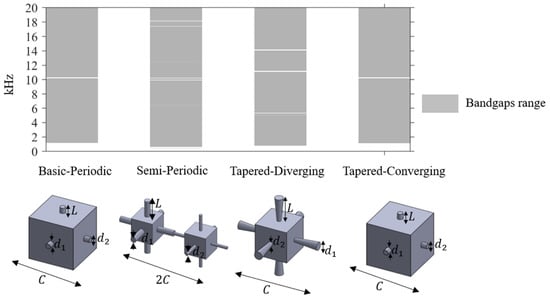
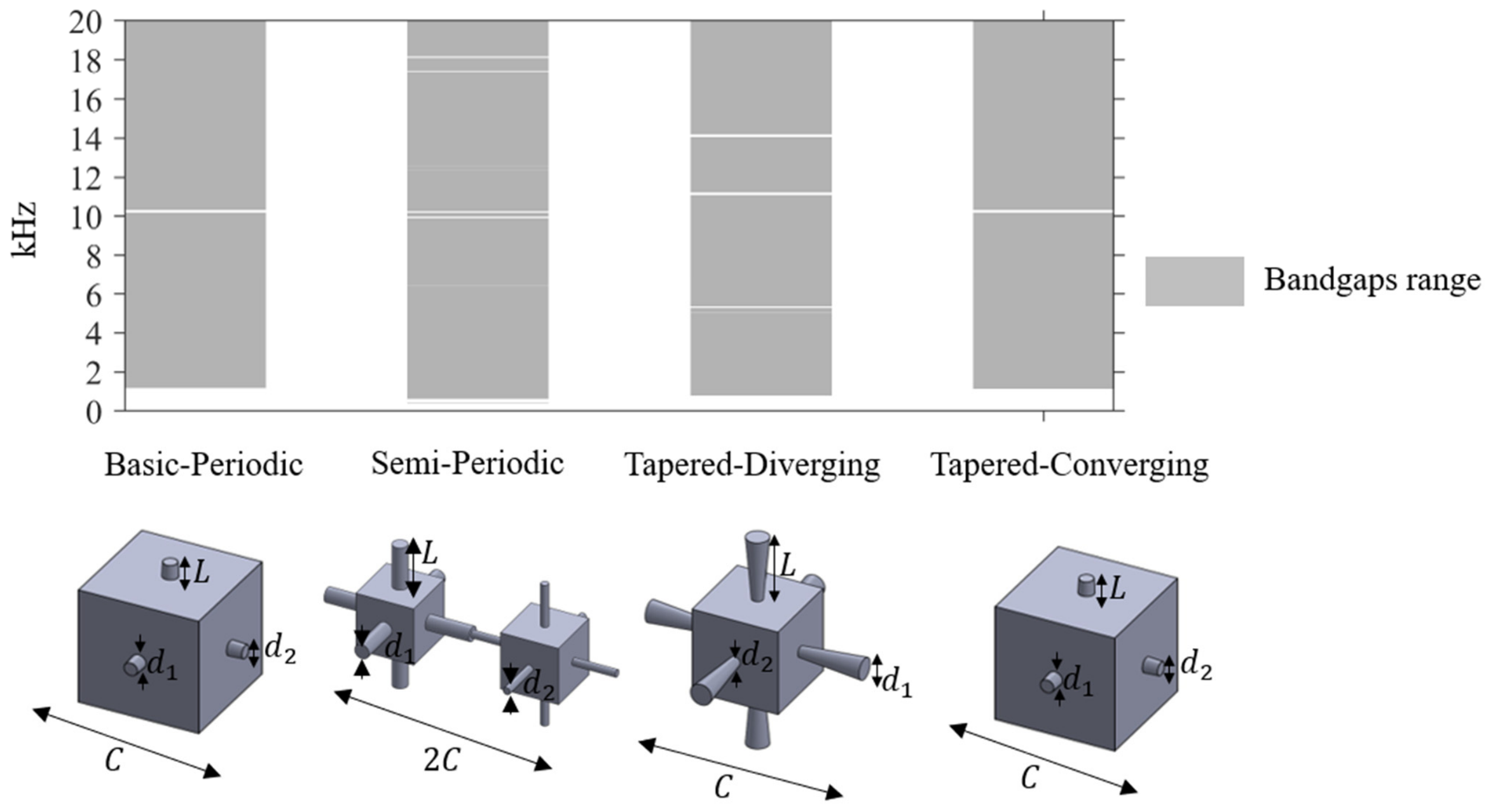
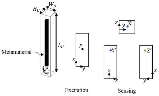
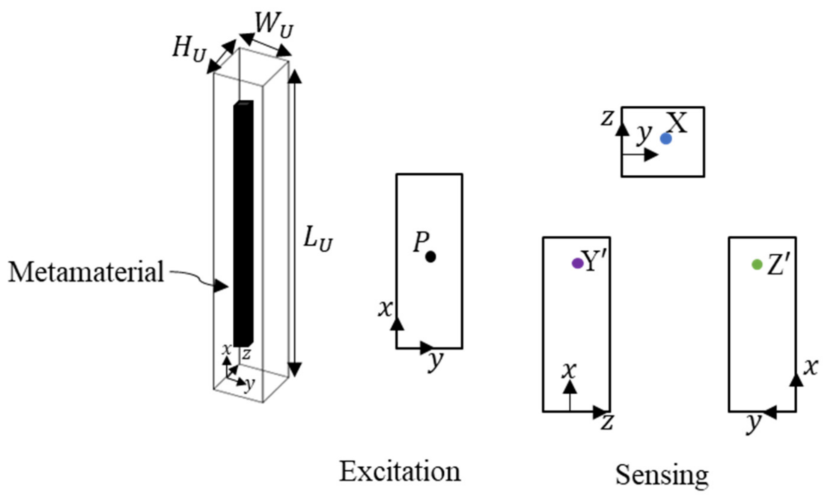
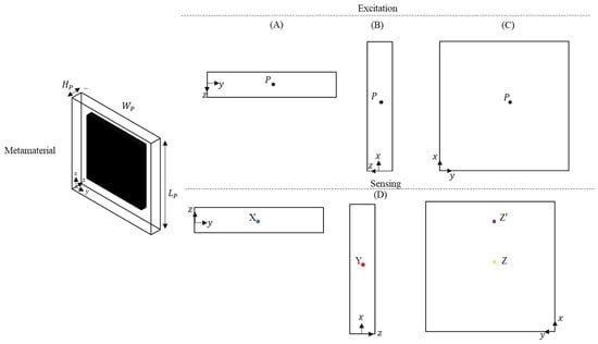
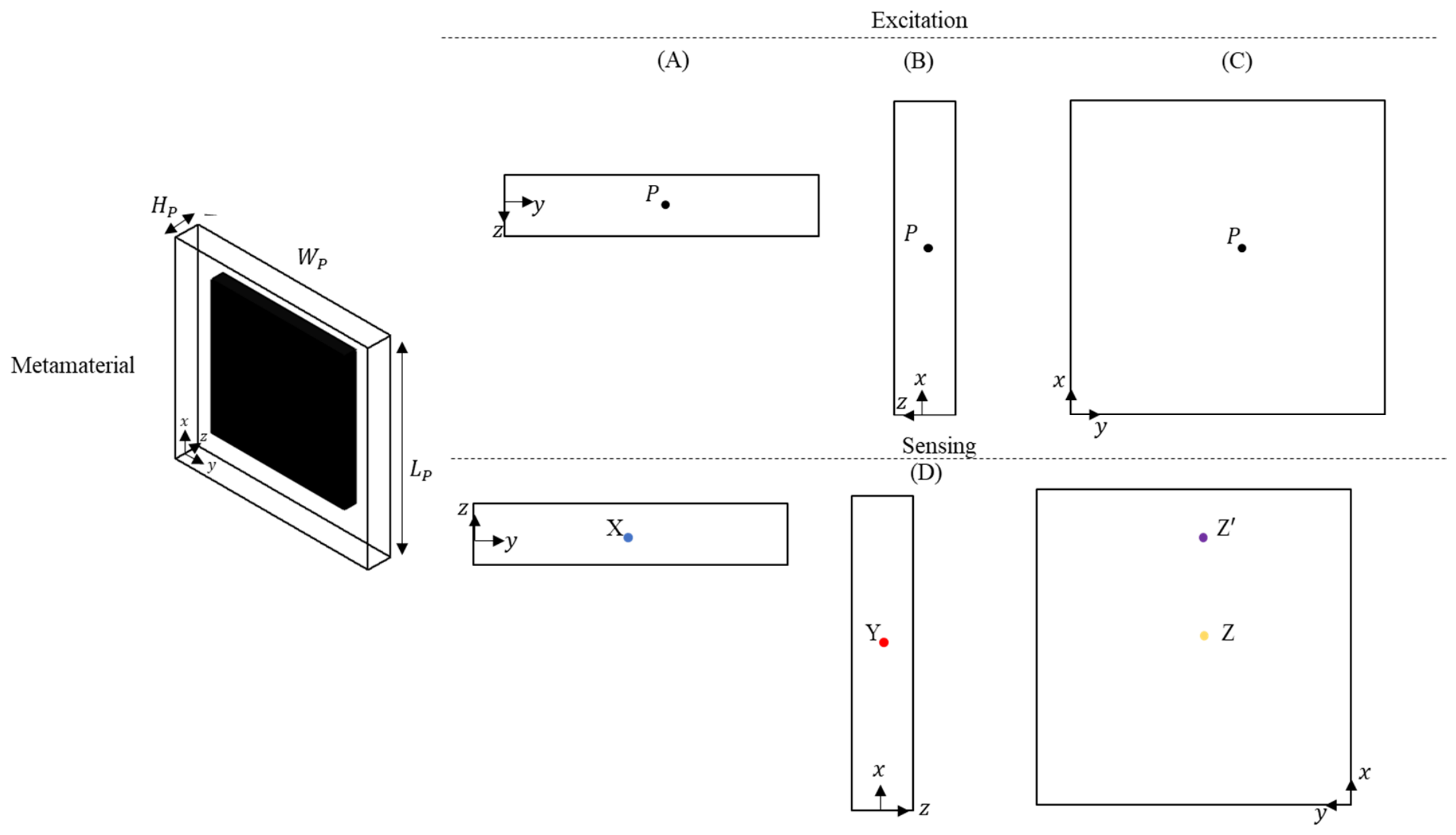
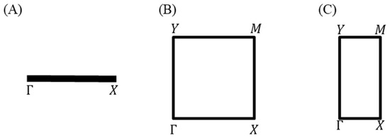
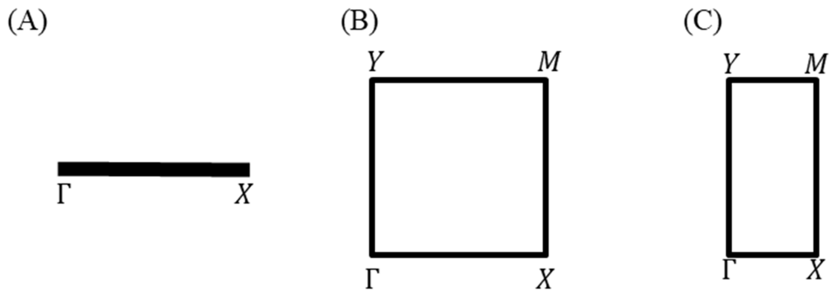
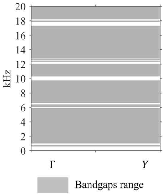
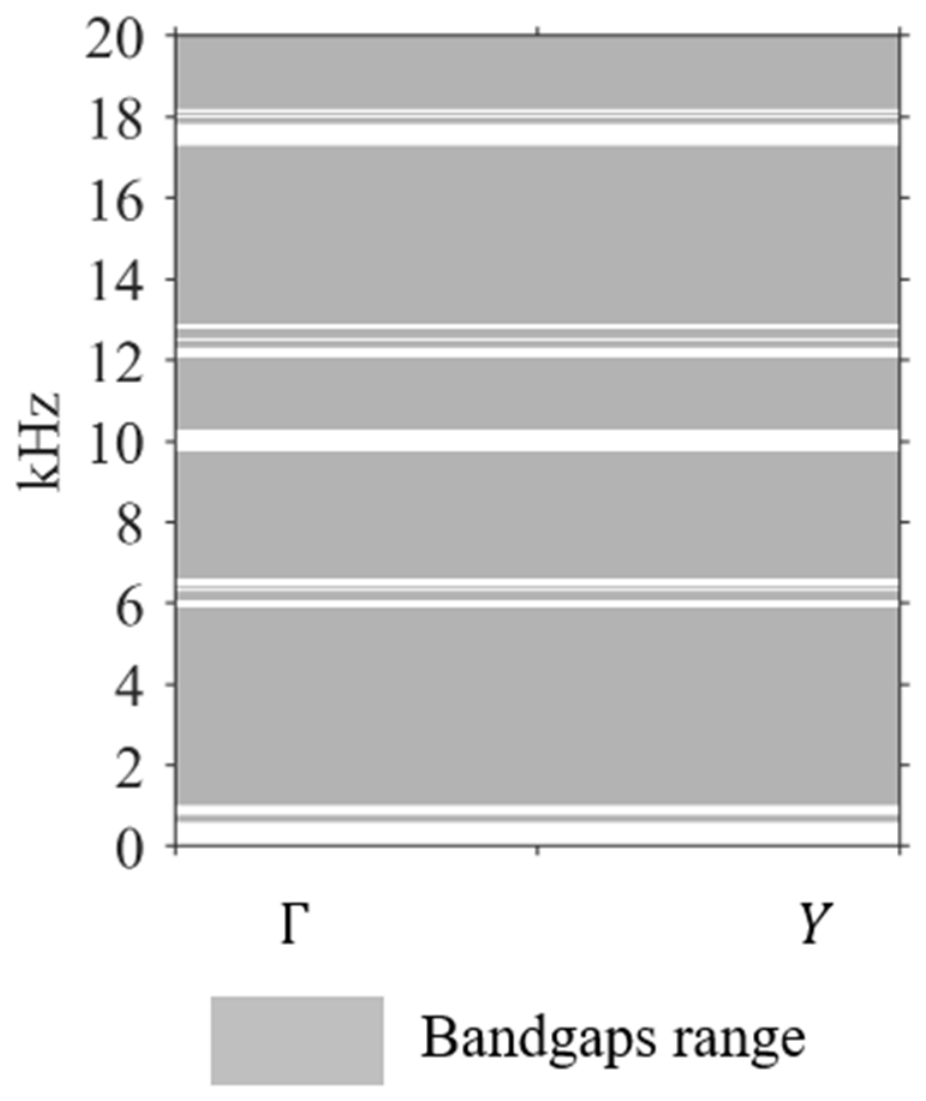
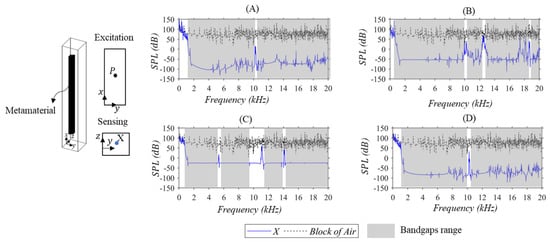
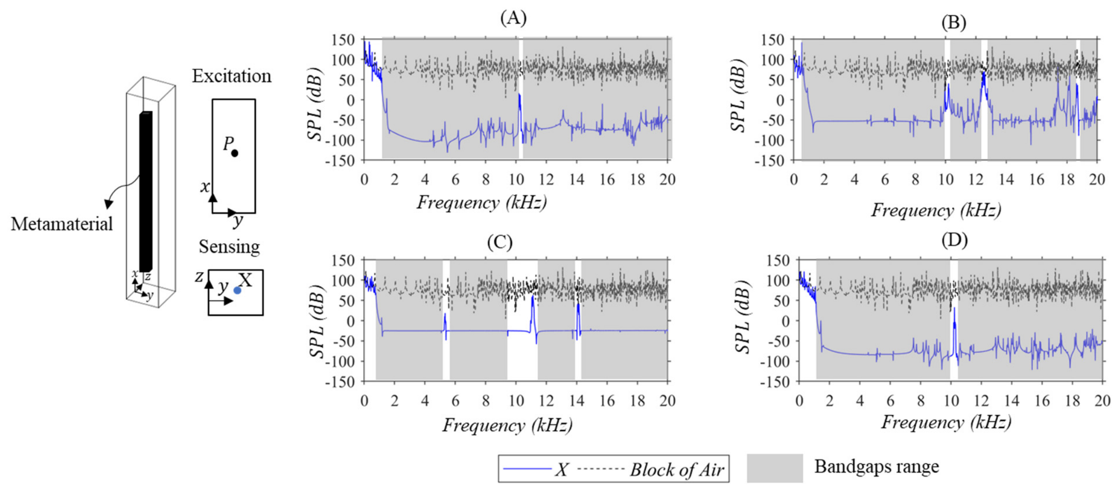
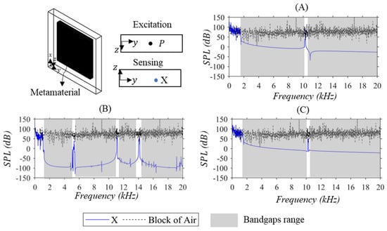
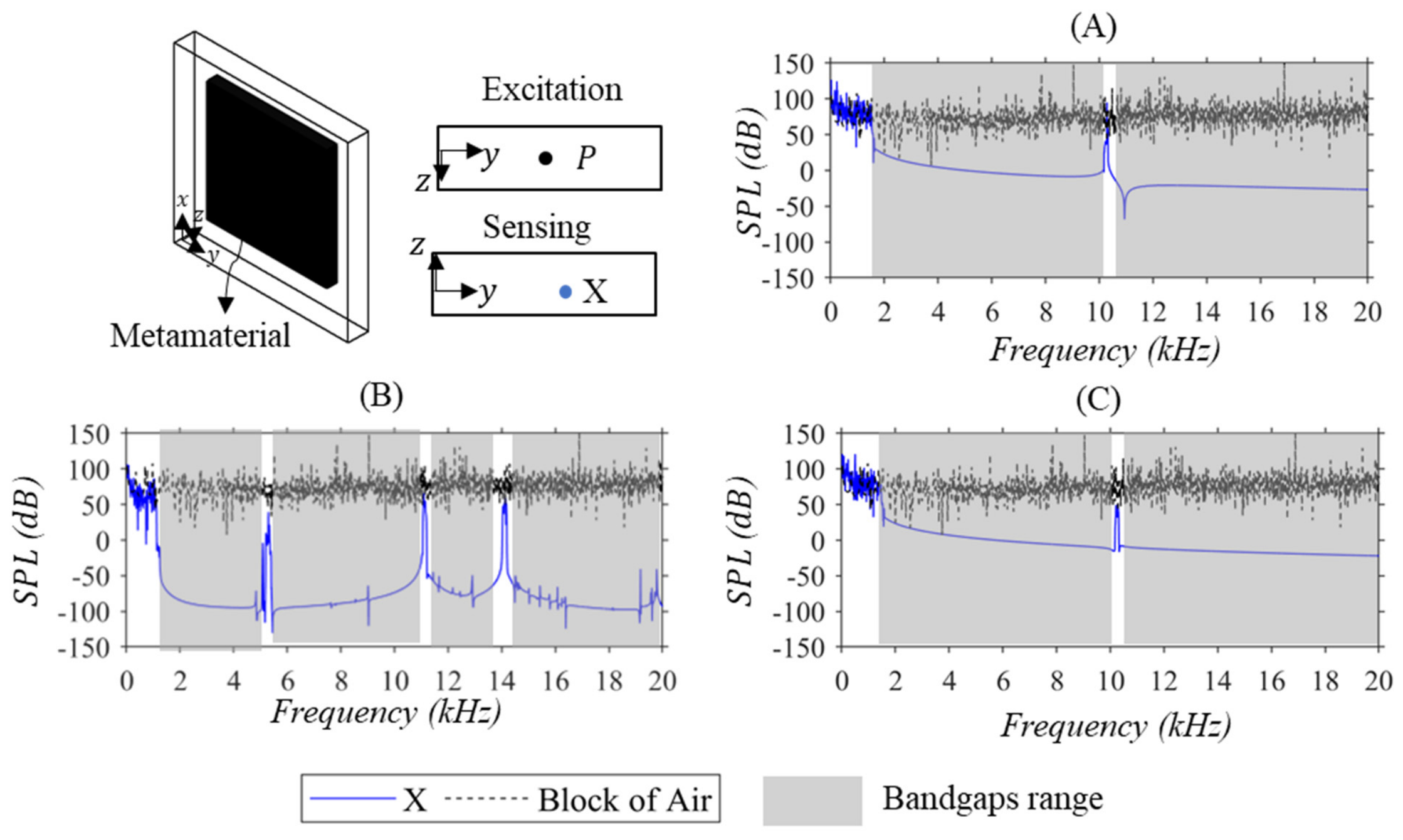
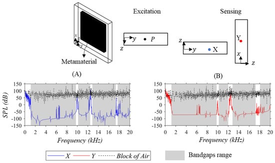
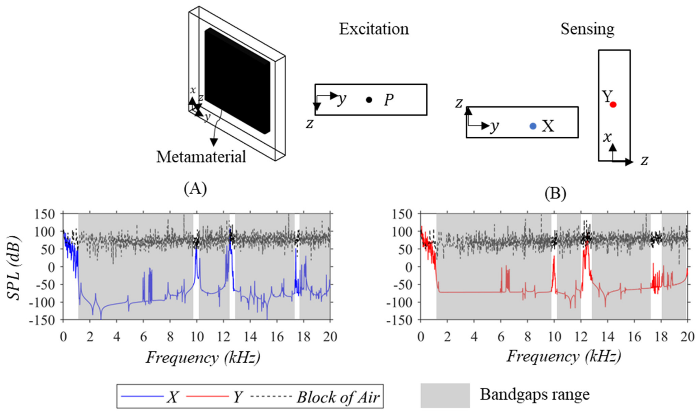
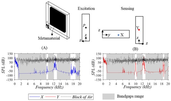
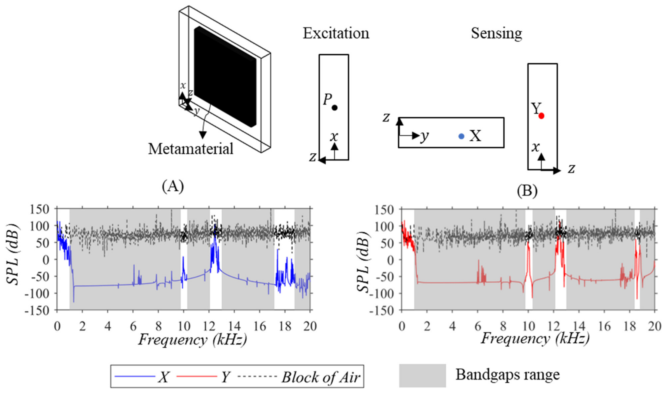
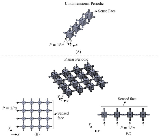
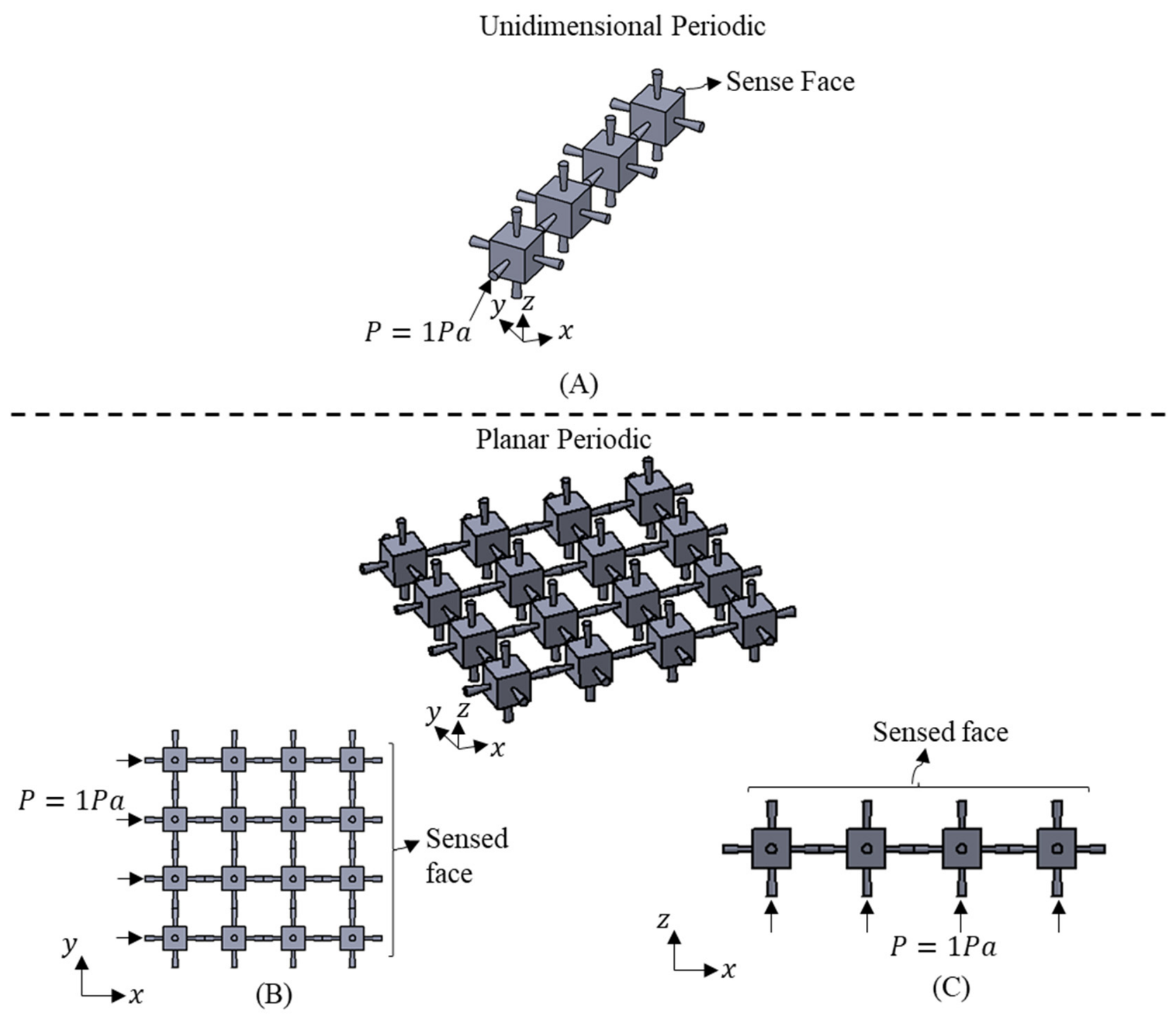
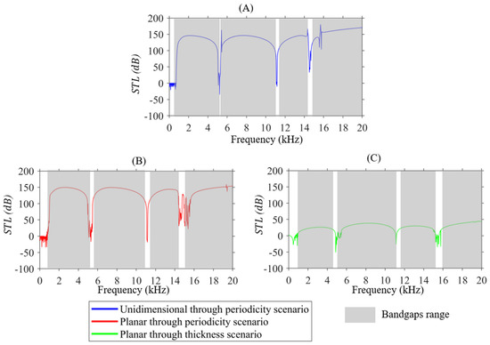
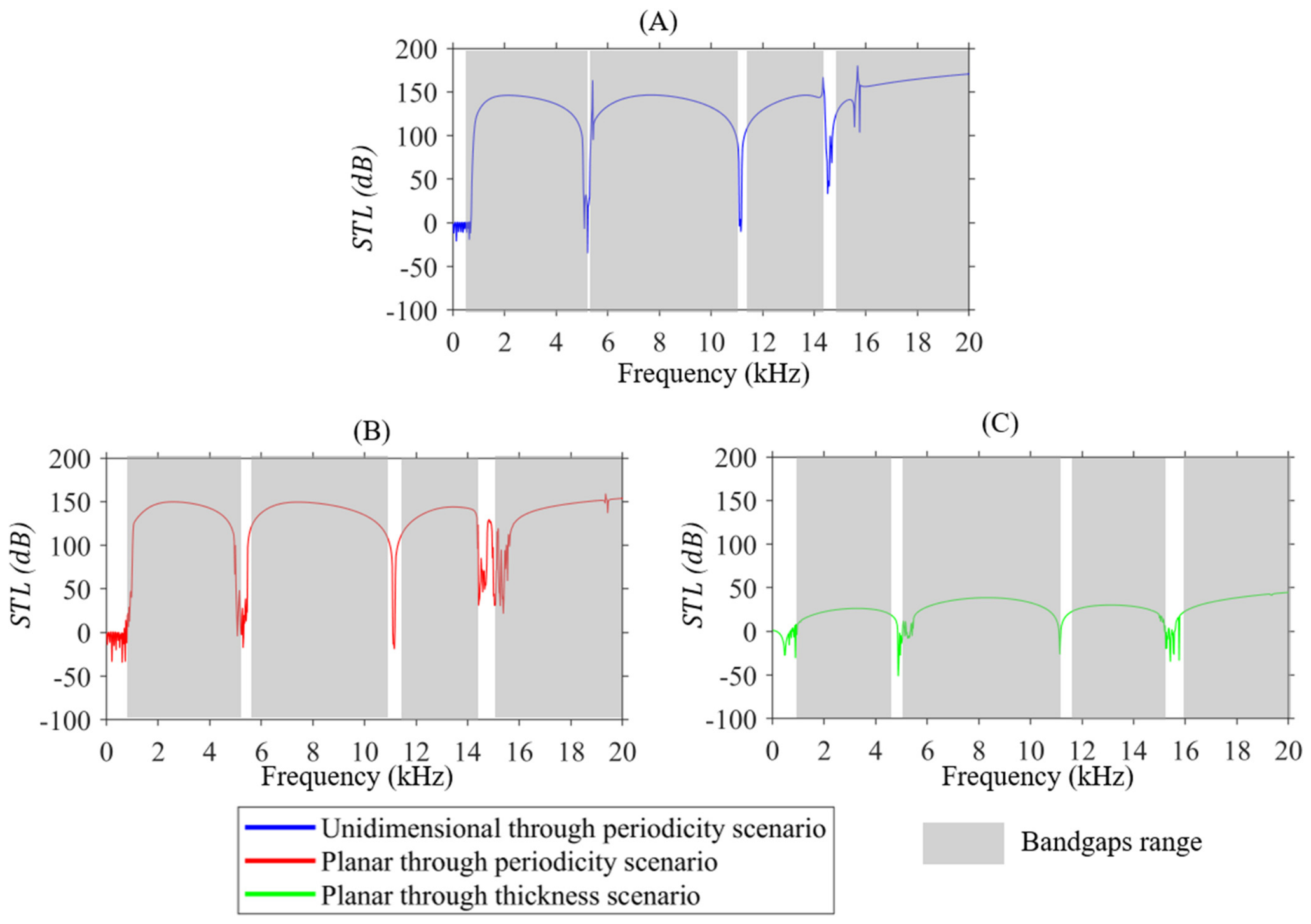
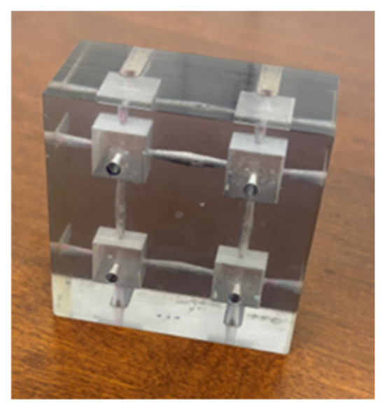
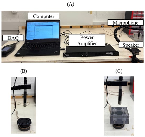
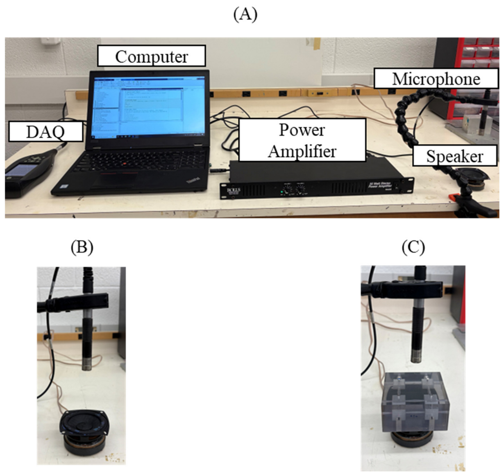
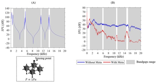
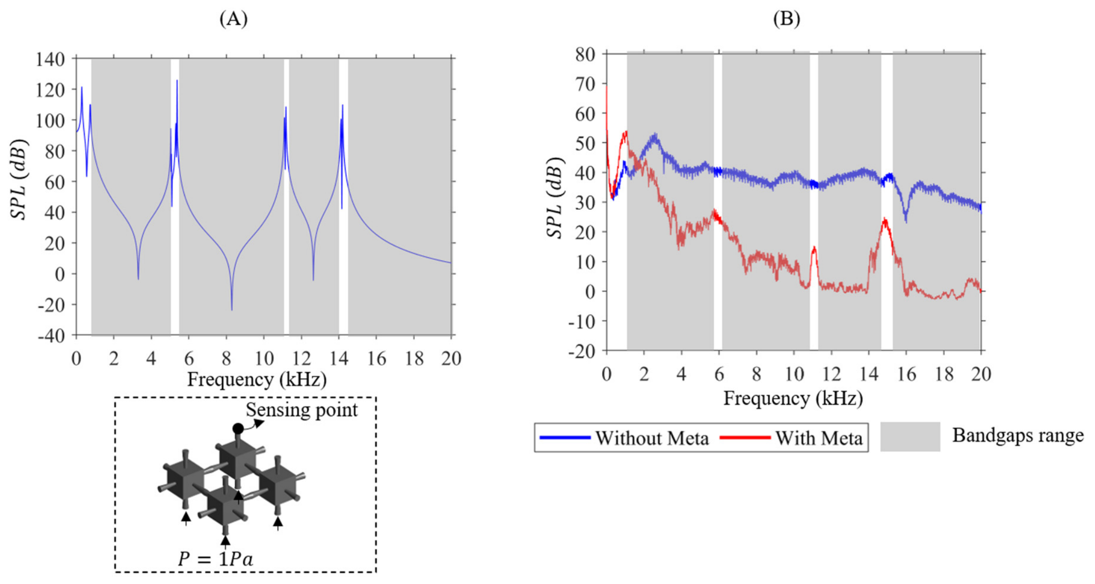

Disclaimer/Publisher’s Note: The statements, opinions and data contained in all publications are solely those of the individual author(s) and contributor(s) and not of MDPI and/or the editor(s). MDPI and/or the editor(s) disclaim responsibility for any injury to people or property resulting from any ideas, methods, instructions or products referred to in the content. |
© 2026 by the authors. Licensee MDPI, Basel, Switzerland. This article is an open access article distributed under the terms and conditions of the Creative Commons Attribution (CC BY) license.