


Featured Application
The findings of this study provide design guidance for impact-resistant structural parts in automotive and aerospace systems, such as hybrid composite drive shafts, energy-absorbing impact boxes, aircraft fuel tanks and housings, and high-pressure gas cylinders. The conducted surface damage assessment offers a practical method for identifying damage mechanisms and structural failures resulting from low-velocity impacts in composite structures.
Abstract
Hybrid composites offer an alternative because the costs of carbon fiber reinforcements are high and the mechanical features of glass and basalt fiber reinforcements are lower than carbon fibers. It is of great importance to use hybrid fiber-reinforced composite tubes to minimize the disadvantages of them and obtain optimum mechanical and impact energy performances according to the working conditions and areas. In this study, basalt fiber reinforcements (BFR) and carbon fiber reinforcements (CFR), [±2]2 BFR/[±2]2 CFR/[±2]2 BFR hybrid, and [±6]2 BFR composite tubes were manufactured using the filament winding process. Low-velocity impact (LVI) experiments were carried out on the BFR/CFR/BFR hybrid and BFR composite tubes under energy levels of 15, 20, and 25 J. As a result of the experiments, liquid penetrant application was carried out to determine the surface damage. To measure the development of damage on the surface, the damaged areas were determined using image processing. No ring-shaped surface damage was observed in the hybrid composites. Although delamination and radial cracks are the most common types of damage in BFR composites, cross-sectional microscopic analyses have revealed that delamination is the predominant damage mode in BFR/CFR/BFR hybrid composites. The hybrid composites exhibited higher maximum loads and lower displacement values at all energy levels.
1. Introduction
Composite materials in thin-walled cylindrical structures have a variety of practical applications in many areas, such as the defense, aviation, marine, space, and energy sectors [1,2]. Filament-wound composite (FWC) tubes are particularly important in the defense and aerospace industries. In the defense industry, rocket bodies, tank gun barrels, rocket launchers, and aircraft and UAV jet fuel tanks and fuselages are manufactured using FWC composites, which exhibit significantly higher internal pressure, fatigue, and impact resistance compared to other composites produced using similar methods. The most preferred fiber reinforcements in FWC composites, depending on their application, are carbon, glass, and basalt fibers, which have emerged as an alternative in recent years [3,4]. The mechanical performance of tubes and tanks produced using the FWC method depends not only on the type of fiber but also on the fiber winding parameters that constitute the production factors, the curing conditions, and the thermomechanical behavior of the layered structure [5]. During the winding of fiber bundles onto a cylindrical mold, the winding tension of the fiber bundles, the uniformity of layer thicknesses, the curing temperature, the viscosity of the resin, the micro-voids formed during winding, the formation of resin-rich and resin-poor areas in the fiber bundles and layers, the quality of inter-laminar adhesion, and the resin’s wettability properties all determine the production quality of FWC composites [5,6]. In addition, the exothermic reactions that occur during the curing process and the differences in the thermal expansion coefficients between the fiber and the matrix lead to permanent internal stresses at the microscale, thereby affecting mechanical performance. Consequently, to control and reduce any residual stresses that may develop during the curing of FWC composites, the curing processes can be carried out at different temperatures and for different durations [7,8].
Carbon fiber reinforcement (CFR) has become the preferred reinforcement material in composite structures, particularly in the aerospace and defense industries, due to its superior properties—such as high strength and stiffness, low weight, and excellent corrosion resistance—compared to other fiber reinforcements [9,10,11,12]. However, the high cost of CFR is a significant disadvantage in terms of the cost-effective production of composites [13,14]. Furthermore, the fact that CFR has high rigidity and a brittle structure imposes certain limitations in terms of formation and progression under impact loading [15,16,17]. For this reason, research into alternative fiber reinforcements that can be hybridized with CFR—thereby conferring deformation capacity to the composite structure whilst maintaining CFR’s superior mechanical properties and reducing costs—is becoming increasingly important [18,19].
In recent years, BFR has emerged as an alternative fiber reinforcement to GFR given its mechanical and cost performance characteristics [20]. Despite the chemical similarity between BFR and GFR, the high levels of ceramic and iron components in BFR provide mechanical properties such as higher strength, impact resistance, and elongation at break compared to GFR, as well as good corrosion, vibration, thermal, and electrical insulation properties [21]. Furthermore, BFR is less expensive than CFR, which makes it an alternative fiber [21,22,23]. These properties make BFR stand out not only as an alternative to GFR but also as a potential reinforcement that can be hybridized with CFR. CFR’s low strain capacity adversely affects fracture toughness and can lead to the development of brittle fracture, particularly in pre-damaged areas of FWC composite pipes following impacts sustained during transport and maintenance [24,25]. In such situations, hybridization with fiber reinforcements possessing high strain capacity can become important in delaying the formation and progression of damage [26,27]. By hybridizing fibers that exhibit brittle behavior and have low deformation with fiber reinforcements that exhibit higher elongation capacity—that is, those with a higher deformation capacity—a hybrid composite structure exhibiting pseudo-ductile deformation behavior can be created [28]. Researchers investigated the initiation and progression of damage during pseudo-ductile deformation behavior under low-velocity impact (LVI) by hybridizing GFR, Kevlar (K), BFR, and CFR fiber reinforcements. It has been established that in hybridized composites, an increase in deformation capacity leads to increased energy absorption and changes in damage behavior. Studies have shown that as deformation capacity increases, fiber fracture damage evolves into delamination and debonding damage [29,30,31,32]. In hybrid composites, different hybrid configurations, layer thicknesses, and fiber winding angles influence mechanical behavior and damage development [2,32,33,34,35]. In FWC tubes, the impact zone directs the development of increasing displacement damage. This leads to a loss of stiffness in FWC tubes. CFR is becoming increasingly important in preventing loss of stiffness. Studies have shown that in hybrid configurations combining GFR and CFR, radial cracks and fiber breakage occur from the surface to the inner layers when the outermost layer is CFR, whilst delamination damage occurs when the CFR is in the middle layer. Studies show that hybrid configurations exhibit pseudo-ductile deformation behavior, resulting in complex damage development and a damage-delaying effect [36,37].
In industrial production, composite hybrid applications are focused on optimal strength and low cost. However, in FWC structures subjected to impact loads or internal pressure, research into the use of hybridization to delay damage propagation, minimize loss of stiffness, maintain structural integrity, and enhance impact resistance has not been sufficiently investigated. Composite cylindrical structures utilized in the defense industry, such as rockets and missiles, may be subjected to damage during transportation, loading onto launch platforms, and the initial launch phase from fighter jets, unmanned aerial vehicles, or helicopters. The reasons for preferring the BFR/CFR/BFR hybrid configuration in this study, and the significant aspects that highlight the originality of the study, are stated as follows.
In the design of hybrid composite tube configurations, BFR is preferred over GFR due to its higher strength and elongation at break. CFR were placed in the middle layers to benefit from their high strength and stiffness, despite their low elongation, which may adversely affect damage progression. The objective of this research is to delay the progression of damage due to the high elongation of BFR in the upper and lower layers. The reason for preferring CFR in the middle layers is to maintain structural integrity thanks to the high rigidity of the composite tubes. FWC tubes can be damaged during their use in rocket bodies while being loaded onto and transported to launch platforms; during the assembly of composite tubes in power transmission lines; and during the assembly and maintenance of aircraft and unmanned aerial vehicle bodies due to drops, impacts from falling objects, collisions with vehicles on the ground, or collisions with birds and drones in the air. In this study, LVI experiments were chosen to simulate these injuries. In studies conducted on FWC tubes, surface damage is generally inspected using macro-scale and micro-scale imaging. However, in general, attempts are not made to quantify and determine the development of surface damage. Despite advances in technology, image processing techniques are not yet effectively used to detect damage growth. This study distinguishes itself from conventional approaches by employing image processing techniques to systematically investigate surface damage growth associated with hybridization configurations. Detailed visualization of surface damage is essential for performing image processing. The dark brown and greenish color of basalt fibers makes normal photographic methods impossible. Therefore, to make it practical in an industrial application and to increase the applicability of the image processing method, the liquid penetrant method and ultraviolet (UV) light application were implemented. This manuscript purposes to contribute to the literature and industry through this method.
In this study, basalt and carbon fibers were hybridized in ±[55°]6 (12) layered composite tubes manufactured through the filament winding process. A comparative analysis was carried out to assess the LVI characterizations of BFR/CFR/BFR hybrid and BFR composite tubes at three energy levels. The main purpose of this research was to assess the effect of CFR reinforcement forming middle layers on the impact responses and damage development of composite tubes. Another objective of our manuscript was to determine the interaction between the damage developments in BFR and BFR/CFR/BFR hybrid composites by examining both the surface damage and damage in the cross-section of the damaged area. Another important part of the study is the use of image processing with a liquid penetrant under ultraviolet (UV) light to quantify the development of surface damage as the energy level is raised. Thus, the areas of damage development were measured through the image processing method. Another important point in the study is the determination of the changes in the predominant damage modes in BFR composites with CFR hybridization.
2. Experimental Procedure
2.1. Materials
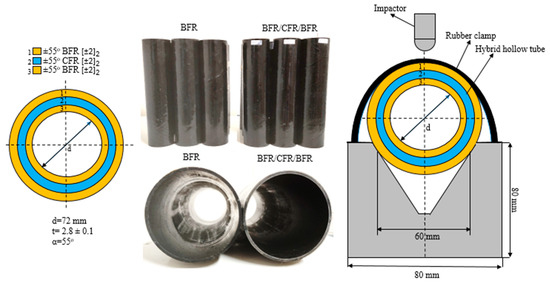
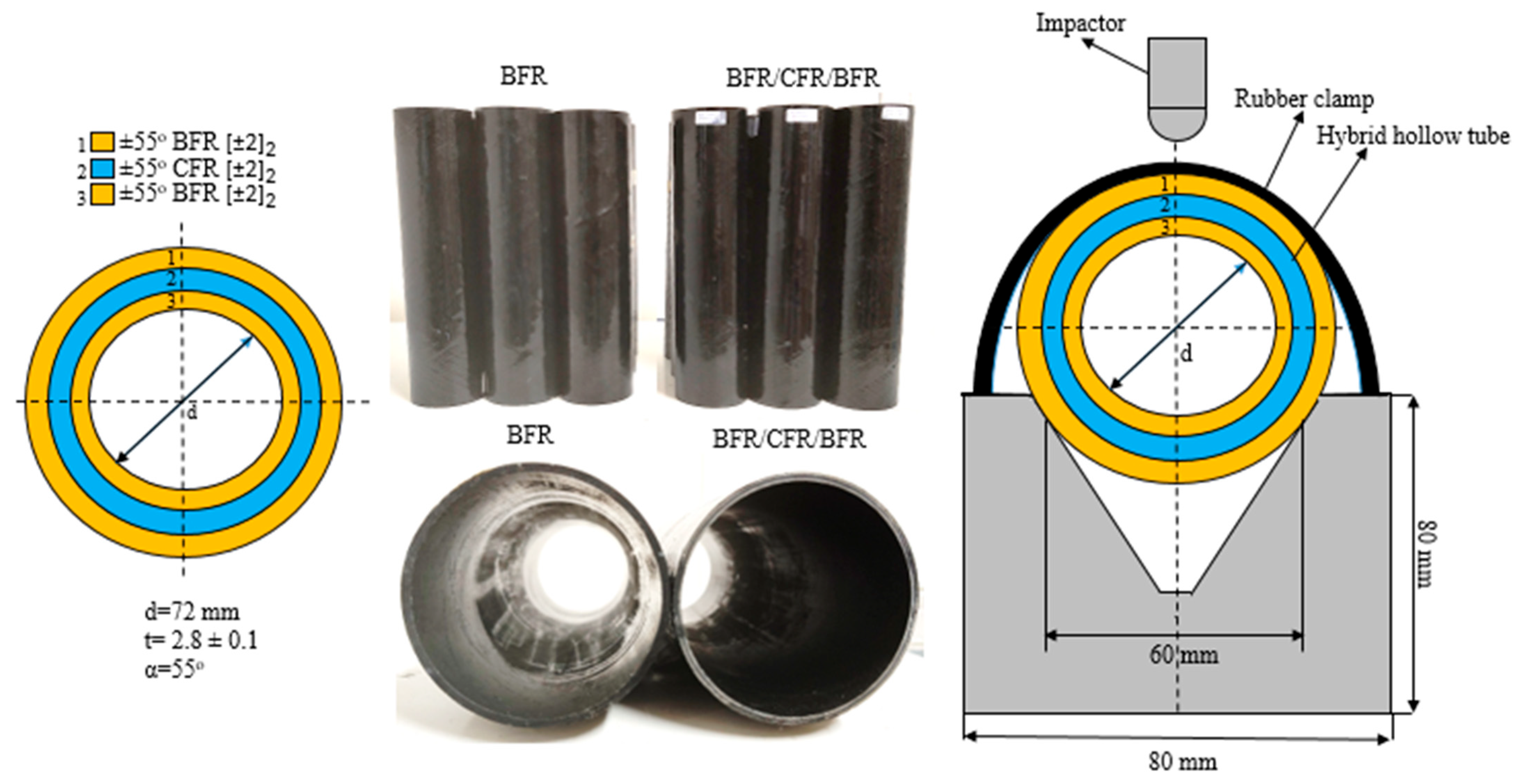
In this study, basalt (Kamenny Vek Dubna Russia, 400 tex/12K, fiber diameter of 11–13 µm) and carbon (Aksa Carbon Yalova Turkey, 400 tex/12K, fiber diameter of 7 µm) fibers were used as fiber reinforcements. For composite cylindrical tubes, these were manufactured on a 72 mm diameter mandrel with ground steel surfaces using an automatic filament winding technique. The composite cylindrical tubes were manufactured on a 72 mm diameter mandrel with ground and polished steel surfaces using an automatic filament winding technique. The polishing process was carried out to ensure that the composite tubes had a smooth and flawless inner surface. A mold release agent was applied to facilitate the easy removal of the manufactured composite tubes from the mandrel. A DGBEA epoxy (Medium-Density, Ciba Geigy Bisphenol A CY22, Basel, Switzerland) was used as the matrix resin. Table 1 presents the properties of the fiber reinforcements and resin used. A winding angle [±55°] and a total of [±6]2 (12) layers were selected as the main production parameters for the production of composite tubes. During manufacture, the fibers were passed through an epoxy resin bath under a tension of 10 N and at a mandrel rotation speed of 20 rpm (fiber velocity of 4.52 m/min), and the impregnation and winding processes were carried out. By heating the resin tank to 40 °C, the wettability of the fibers by the epoxy was improved. A tension of 10 N was applied to the fiber bundles to ensure their optimum wettability and to ensure intimate contact between the layers and a good interface. After the [±6]2 (12) layer winding process was performed, the production of composite tubes was completed with pre-curing and final curing processes at 135 °C and 150 °C for 3 h each. Then, the composite tubes were cut into dimensions of 300 mm (Izoreel Manufacturer Company Izmir Turkey). The average dimensions of the composite tubes are presented in Figure 1. Hybrid composite samples were designed and manufactured with [±2]2 (4) layers of BFR, [±2]2 (4) layers of CFR, and [±2]2 (4) layers of BFR from outer to inner layer. The fiber arrangement of the hybrid composites is schematically illustrated in Figure 1. The same production process has been used for hybrid composite tubes. The manufactured samples exhibited a mean wall thickness of 2.8 ± 0.1 mm.
Table 1.
Mechanical properties of fibers and matrix materials [38].
Figure 1.
BFR/CFR/BFR hybrid configuration and V-bed fixture.
2.2. Test Method
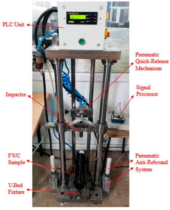
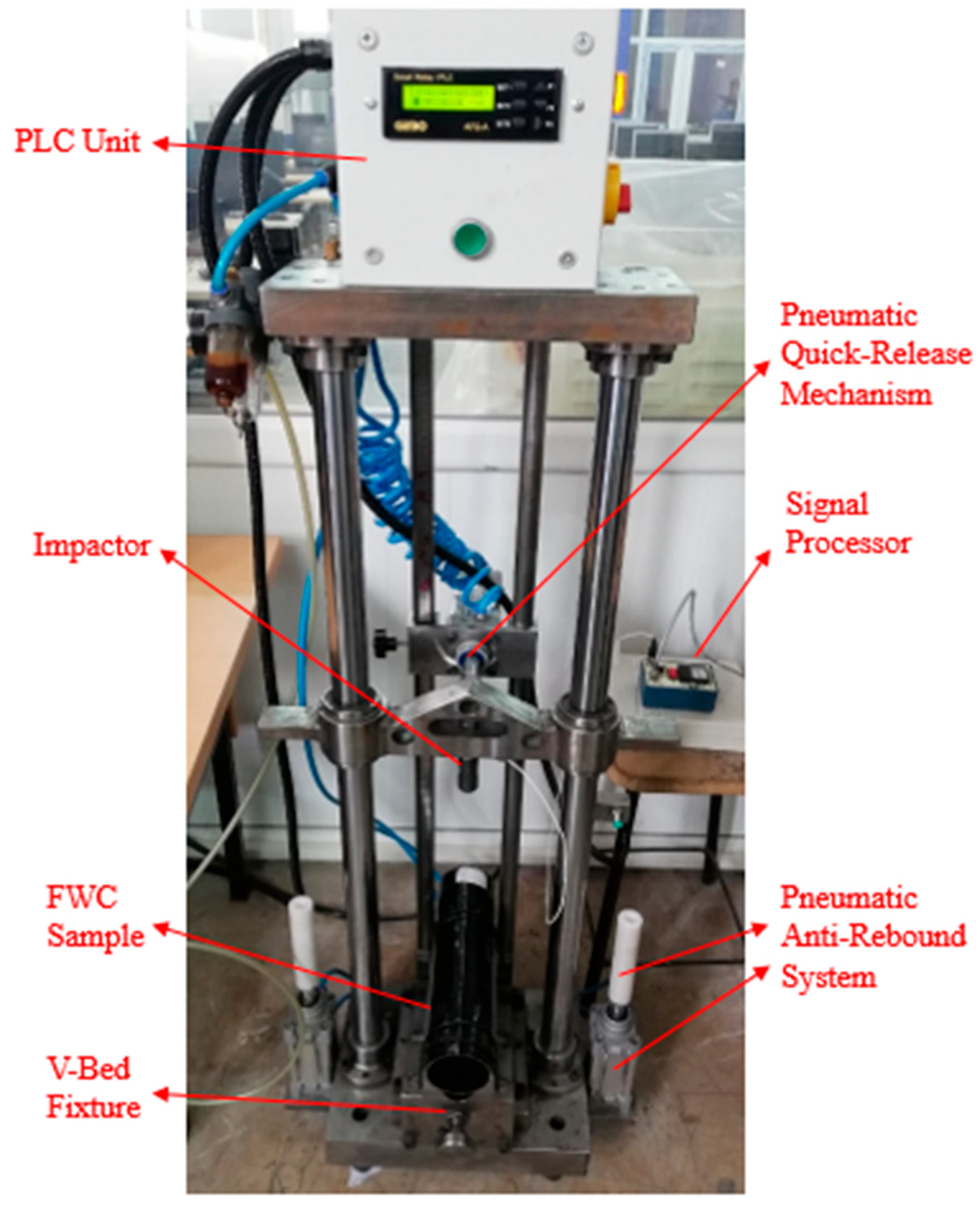
LVI tests were conducted on [±55°]6 BFR and [±55°]6 BFR/CFR/BFR hybrid hollow composite tubes at energy levels of 15 J (2.31 m/s), 20 J (2.67 m/s), and 25 J (2.98 m/s) at ambient room temperature (23 °C) in accordance with ASTM D7136/D7136M [39]. The experimental setup of the universal LVI test unit is presented in Figure 2. During the experiment, load time data were recorded from the load sensor of the LVI unit via the NI signal express program while the impactor was in contact with the composite damaged area. The data sampling rate in the LVI impact unit is 25 kHz. The mass of the impactor is 5.6 kg. A hemispherical impactor tip with a 12 mm diameter was utilized. The composite tubes were meticulously positioned and clamped in the V-bed fixture of the LVI fixture before the experiment. Friction in the V-bed fixture was neglected. Rubber clamps were used in the V-shaped fixture to prevent the specimens from rolling, and the specimen was secured. In the LVI tests, a single impact was applied to each specimen. Thanks to the integrated pneumatic anti-rebound prevention mechanism fitted to the test machine, the impactor was automatically caught at the moment of rebound, thereby preventing secondary impacts from occurring. Following the acquisition of force and time data from the LVI test unit, displacement and energy were calculated based on Newton’s second law. Here, V0 denotes the impact velocity, m is mass, load is F, δ is displacement, and g is the acceleration due to gravity. The equation for the rebound energy is given in Equation (4).
Figure 2.
LVI test setup.
The representative force–displacement and force–time curves presented in the figures—selected from three replicate tests (n = 3) conducted under each condition—were determined using the median response criterion. Specifically, the test specimen whose total absorbed energy and peak displacement values were closest to the arithmetic mean of the triplet was selected to represent typical behavior rather than outlier values. The average values of the specimens tested three times, along with their standard deviations, are presented in Table 2.
Table 2.
Mean values of LVI test results.
The fiber volume ratio of the samples was found to be approximately 0.61 according to the ASTM D2584 burn-off test [40]. Three independent samples were tested for each configuration and energy level, resulting in a total of 18 LVI tests. The statistical results are presented in the section on statistical analysis. Following the impact tests, the damaged surfaces were cleaned. To facilitate macro-scale damage analysis, a penetrating fluid (Pfinder 900, 9.25 mm2/s, bright greenish-yellow fluorescent) was applied to the impact zones of the BFR and BFR/CFR/BFR hybrid composite pipes for 15 min for each energy level via capillary action without applying external injection pressure. The purpose of leaving the penetrant to stand for 15 min is to allow sufficient time for it to penetrate capillary cracks. After penetration, the damaged surface was wiped with a cleaner. Then, the impacted damage zones were illuminated using ultraviolet (UV) light, and high-resolution images were captured. Subsequently, the image processing method was applied to determine the impacted damage zones. To calculate the mean damaged surface zone, image processing was carried out on images captured from the surfaces of three samples subjected to impact at the same energy level. To further identify their types, micro-scale observations (Dino-Lite Microscope, AnMo Electronics Corporation, New Taipei City, Taiwan) were performed on the cross-sections of the impacted zone. For micro image examination, the samples were cut at the centers of the impact damages, and the obtained cross-sections of damaged surfaces were polished by using 1200-grit abrasive paper to achieve smooth surfaces.
2.3. Image Processing Method
LVI tests were performed on [±55°]6 BFR and [±55°]6 BFR/CFR/BFR hybrid composite pipes at energy levels of 15 J, 20 J, and 25 J, in accordance with the ASTM D7136/7136 M standard [39]. Following the application of LVI tests, a penetrating liquid was applied into the damaged area of the composite pipes. This process increased the visibility and contrast of macro cracks on the damaged surfaces. Image processing techniques were used to measure the numerical values of the damaged regions at various time points. The image processing processes applied for surface damage analysis began by capturing raw macro-scale images of the penetrated damaged surfaces under UV light. A standard digital image processing procedure was carried out using ImageJ software (Version 2, National Institutes of Health, Bethesda, MD, USA). The images were photographed under UV light using a reference scale. The RGB images were converted to greyscale, and the yellow-green damage images were isolated. Filtering was performed by applying a binary operation. The area was calculated by converting the number of pixels obtained into mm2. The image processing processes were completed by determining the numerical values of the surface damaged areas. To verify the accuracy of the experimental results, images and image processing were executed three times at each pulse energy level. The results are presented in a table with mean values and standard deviations.
3. Experimental Results
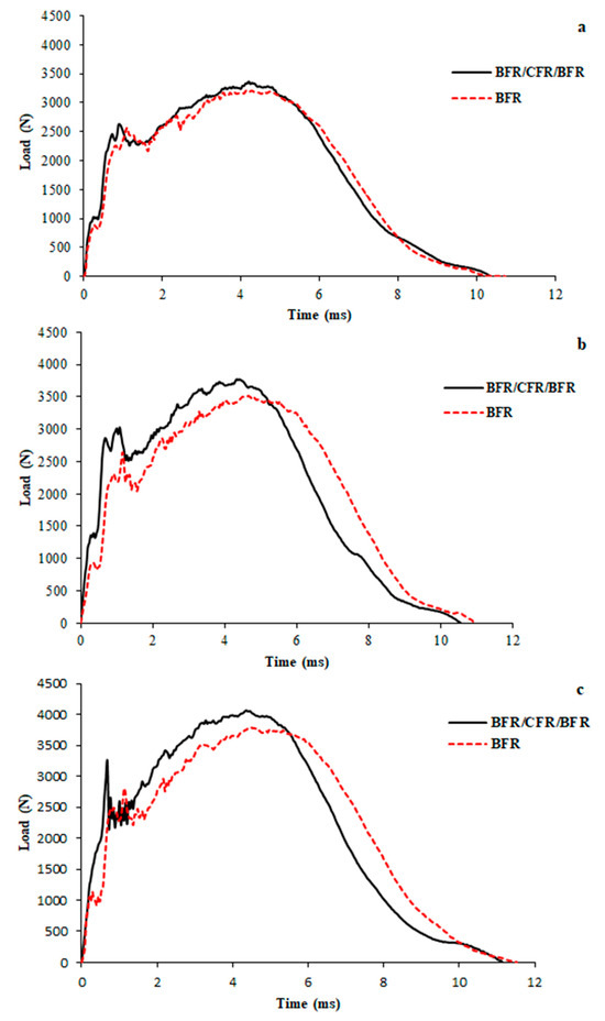
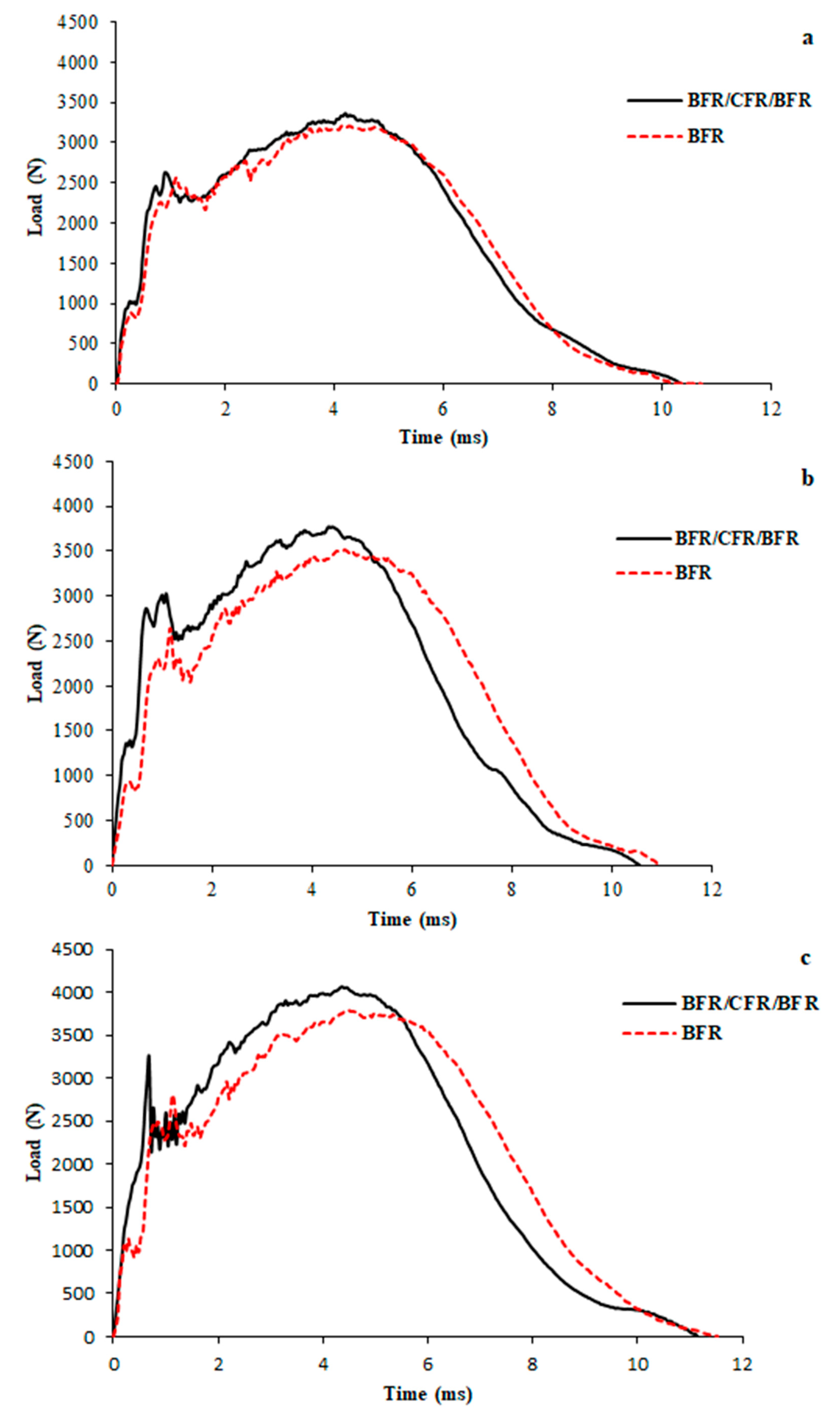
The load–time responses during impact loads of the BFR and BFR/CFR/BFR hybrid composite samples under the three different impact energies are exhibited in Figure 3. When examining the load–time graphs, it can be discerned that the changes in the contact load over time exhibit closed-end curves resembling a bell-shaped curve. Upon contact with the impact load sensor, it can be noticed that the contact load increases upon impact, reaches its maximum, and subsequently decreases due to progressive damage. The load drops can be attributed to stiffness losses in the material resulting from the local delamination damage triggered by matrix cracks. These types of damage, which cause a loss of rigidity, significantly affect load transfer between the fiber reinforcement and the matrix material. When sufficient load transfer occurs, it causes stiffness losses from the matrix material to the fiber reinforcement, affecting the structural integrity of the composite structure. Matrix cracks are types of damage that occur in the matrix material, which is the weakest part of the composite, when the composite is subjected to impact. Debonding occurs when cracks, which cluster and multiply as the impact load is transferred from the matrix material to the fibers, separate the fiber/matrix interface, leading to progression of the damage [23,41]. Debonding intensifies and covers a portion of the fiber surface. As it progresses, it spreads to adjacent fibers within the fiber bundles, multiplies, and tends to coalesce. Thus, debonding that clusters and merges within the layers creates interlayer delamination [42,43,44]. During impact contact, these damages cause localized rigidity losses in the layers subjected to the impact. Local stiffness losses in each layer reduces the load-carrying capacity of the composite tube, resulting in load drops in the load–time curve until the load is transferred to the underlying layer as damage progresses. As damage progresses, the load-carrying capacity (rigidity) of the underlying layers increases up to a critical stress threshold. Associated stress concentrations promote the merging of matrix cracks, leading to interfacial decomposition and subsequent layer separation, ultimately resulting in loss of rigidity. Consequently, this leads to reductions in load values. In general, the elastic region of the impact load curves up to the maximum load point represents the overall stiffness region of composite tubes, and spherical bending occurs within this region under impact loading. After the impact load reaches its maximum value, local bending occurs as a result of the initiation and propagation of damage within the layers. It is thought that minor fluctuations in the contact load within the impact region of the composite samples under impact loading can be attributed to the formation of matrix cracks. In addition, it is considered that the accumulation of matrix cracks may induce fiber–matrix debonding, subsequently leading to local delamination [12,20,22].
Figure 3.
Load–time graphs of BFR and BFR/CFR/BFR hybrid samples at 15 J (a), 20 J (b), and 25 J (c).
In the load–time graphs provided in Figure 3a–c, it can be examined that when the energy level rises, the maximum impact loads and the corresponding maximum time also increase. When the impact load–time responses of the BFR/CFR/BFR hybrid samples are examined with increasing impact energy levels, noticeable variations appear in the local curve behaviors, particularly in the instantaneous load drops observed in the impact regions. This case is particularly true in the instantaneous load drops observed during the initial stages. At an impact energy of 25 J, noticeable variations were observed in the instantaneous load–drop curve within the impact region of the hybrid sample. This response can be related in damage formation and propagation at the interface between the BFR and CFR layers. The damage propagation in this region indicates a rapid transition from matrix cracking to delamination. However, it can be interpreted that during the contact of the force, the CFR intermediate layers, owing to the higher rigidity of CFR compared to BFR, contribute to the increase in force. It can also be stated that the hybrid composite pipe maintains its structural integrity.
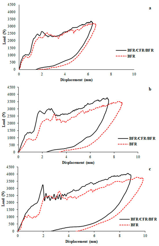
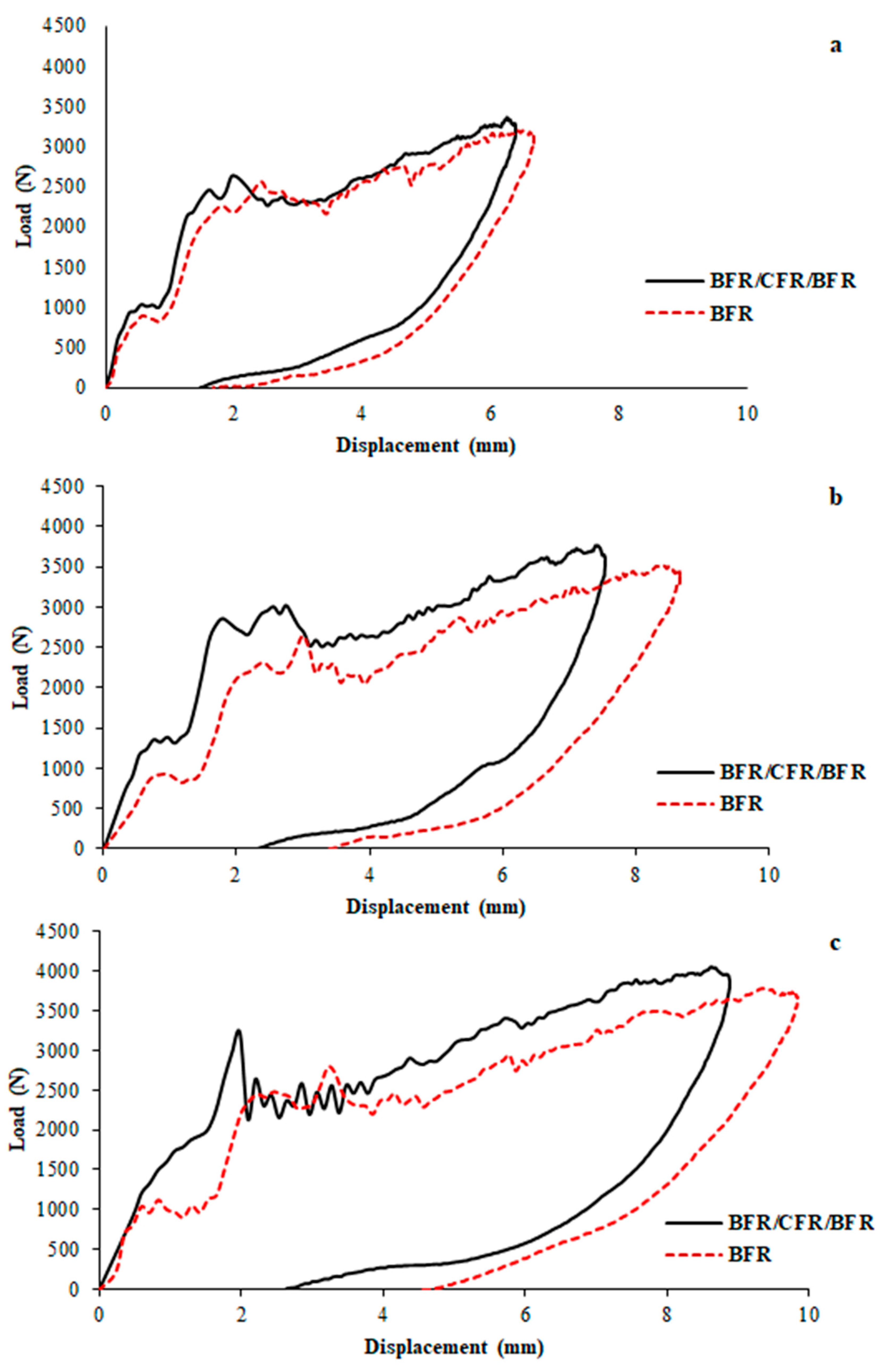
The difference in stiffness between the BFR and CFR layers significantly influences the formation and progression of damage. As seen in the graphs, the hybrid samples exhibit a higher maximum load compared to the BFR samples. In this case, it is revealed that the CFR layers, which have higher stiffness than BFR, have an essential role in increasing the impact load carrying capacity of the hybrid structure. Conversely, BFR samples exhibit a longer contact time, resulting in higher deformation and energy absorption capacity. When comprehensively evaluated, the addition of CFR layers plays a notable function in increasing the maximum load and changing the contact time properties of hybrid composites. Load–displacement plots from LVI tests performed at 15 J, 20 J, and 25 J are introduced in Figure 4. A detailed examination of these plots reveals that the impact load response exhibits distinct two-stage behavior with increasing displacement. The first stage corresponds to the beginning of initial damage through local elastic deformation throughout the pipe wall’s thickness [15,16,20].
Figure 4.
Load–displacement graphs of BFR and BFR/CFR/BFR hybrid samples at 15 J (a), 20 J (b), and 25 J (c).
At 15 J, the load–displacement responses of the BFR/CFR/BFR hybrid and the BFR composite samples exhibit similar overall trends. However, it is pointed out that the BFR samples show more pronounced load fluctuations, indicating a higher degree of local damage development. As mentioned earlier, within the second region of the curve, the intermediate CFR layers in the hybrid samples provide greater resistance to bending loads compared to the BFR samples. The lower displacement values observed in hybrid samples compared to BFR samples are thought to be related to the increased stiffness provided by the CFR interlayers. Figure 4b,c clearly show that as the energy level rises, both the maximum load and the difference between the maximum displacements for the BFR/CFR/BFR hybrid and BFR samples increase. At an impact energy of 25 J, the increase in the difference between maximum displacements is particularly pronounced for the hybrid samples, as given in Figure 4c.
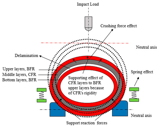
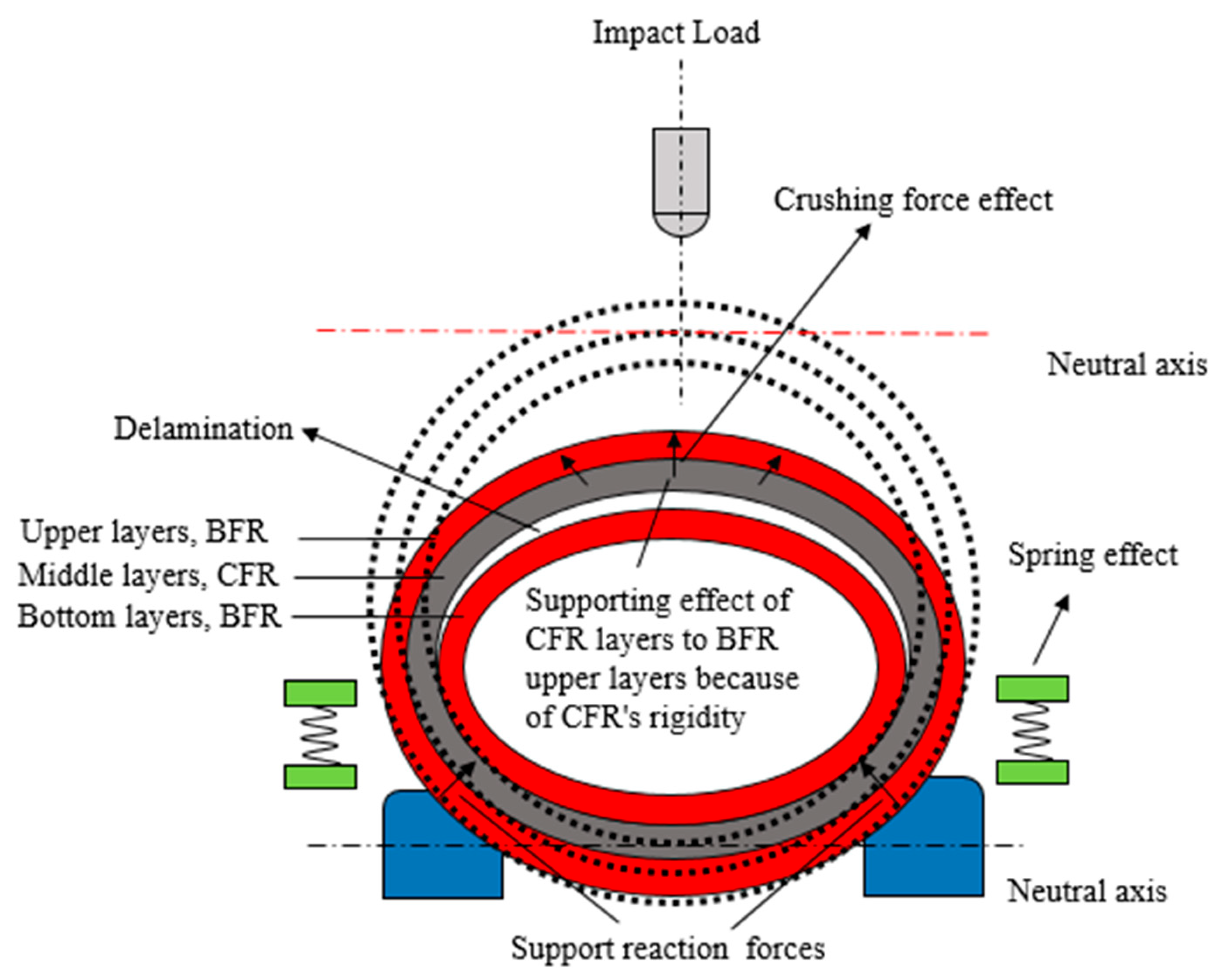
The load–displacement curves at 20 J and 25 J reveal that the hybrid samples exhibit small-scale up and down fluctuations at relatively lower load levels compared to the BFR composites. This behavior is interpreted to be due to the higher stiffness of the intermediate CFR layers than the BFR. From the analysis of force–displacement curves, it appears that small-scale, rapid oscillations are associated with matrix cracking and fiber–matrix separation, while larger-scale oscillations correspond to delamination. This behavior is particularly evident in the BFR/CFR/BFR hybrid samples at 25 J (Figure 4c). The high stiffness provided by the CFR reinforcement reduces deflection along the impact load axis, which is thought to reduce inter-laminar delamination during the impact event. It is interpreted that increased deflection during impact facilitates and accelerates the propagation of delamination damage. This effect is particularly evident in BFR samples. The curves demonstrate that the CFR reinforcement in the middle layer limits delamination by reducing displacement. Furthermore, as schematically illustrated below, delamination in hybrid composites is more likely to occur predominantly in the interface region beneath the CFR layers rather than at the upper BFR/CFR interface. This observation is supported by micrographic analysis and the liquid penetrations of samples following penetration tests.
It is thought that the intermediate CFR layers of the hybrid sample will be forced to crush the layers in the direction of the impact axis at the upper BFR interface, whereas it is forced to separate at the lower BFR interface (Figure 5). Consequently, the upper sections of the CFR layers are exposed to compression, whereas the bottom sections undergo tension. It is considered that this phenomenon becomes apparent as the energy level increases, as shown in Figure 4b,c, at the 20 J and 25 J. When the mid-layers of FWC composite tubes are reinforced with CFR, the approximate mean increase in maximum load at 15 J, 20 J, and 25 J of the hybrid samples is 3.9%, 6.4%, and 7.2%, respectively. The reductions in displacement values at energy levels of 15 J, 20 J, and 25 J are 41.3%, 36.1%, and 50%, respectively. At the same energy levels, CFR reinforcement in the middle layers of BFR composite tubes resulted in an increase in maximum load while significantly affecting displacement and leading to substantial percentage reductions. It is thought that an increase in displacement is a significantly influential parameter in formation and damage growth. It can be interpreted that CFR reduces displacement, which is the major reason for debonding and delamination, thus delaying initiation and damage growth. In this study, when the data obtained for hollow BFR/CFR hybrid tubes are compared with the values applied at 15 J and 20 J to GFR and CFR hybrid FWC tubes under internal pressure in Gemi’s (2018) [36] study, it can be stated that BFR/CFR hybridization exhibits remarkably good impact performance. In Gemi’s study, the best low-velocity load values at 15 J and 20 J were obtained for hybrid tubes with a CFR inner layer. However, it was stated that the experimental results for hybrid tubes with a CFR middle layer showed values similar to those for hybrid tubes with a CFR bottom layer [36]. Despite being subjected to internal pressure, GFR/CFR hybrid tubes exhibit impact load values close to those of hollow BFR and CFR hybrid tubes. In Gemi’s study, as the energy level increased, the impact loads of hybrid tubes with CFR bottom layers and CFR middle layers showed similar values. Maziz et al. (2021) reported in their theoretical and experimental studies on GFR/CFR hybrid FWC tubes that when the GFR layers are located in the lower and middle layers, the displacement value resulting from impact increases [45]. However, the displacement values of hollow CFR/BFR hybrid tubes were found to be lower than those of GFR and CFR. This suggests that BFR exhibits better impact behavior than GFR when hybridized with CFR. Consequently, it reveals that BFR reinforcements are an alternative fiber to GFR. Farhood et al. (2021) applied LVI tests to hybrid FWC tubes with different ratios of CFR and GFR and determined that the greatest damage development occurred in hybrid tubes with a GFR middle layer [46]. Although the top and bottom layers are CFR, the middle layer’s GFR is considered to cause the most damage and its growth due to its low rigidity. In the LVI characterization study of BFR/CFR hybrid FWC tubes, it can be interpreted that the presence of high-rigidity CFR in the middle layer has a damage-delaying effect due to displacement reduction. Changes in dominant damage types and damage delay effects are clearly visible in damage analyses.
Figure 5.
Supporting effect of CFR layers to BFR upper layers because of CFR’s rigidity.
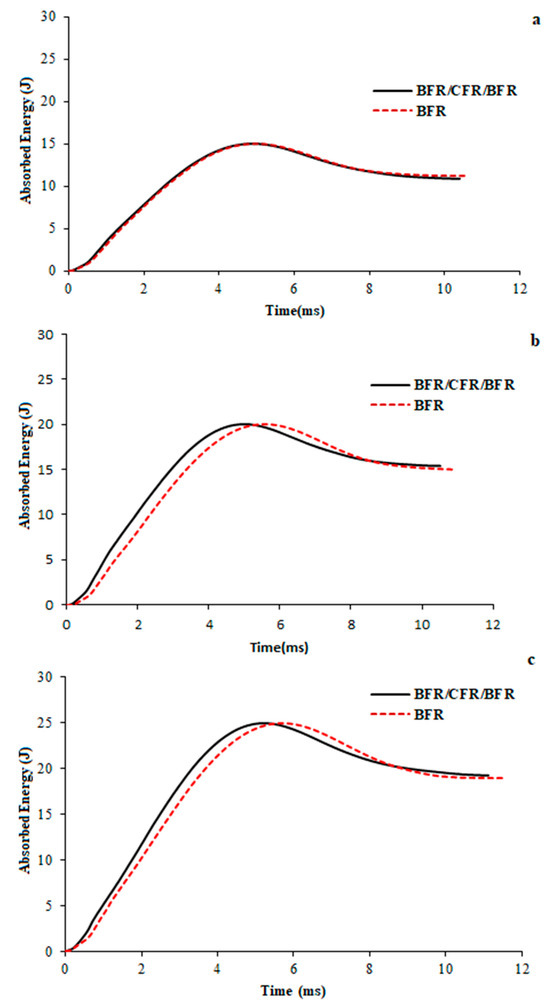
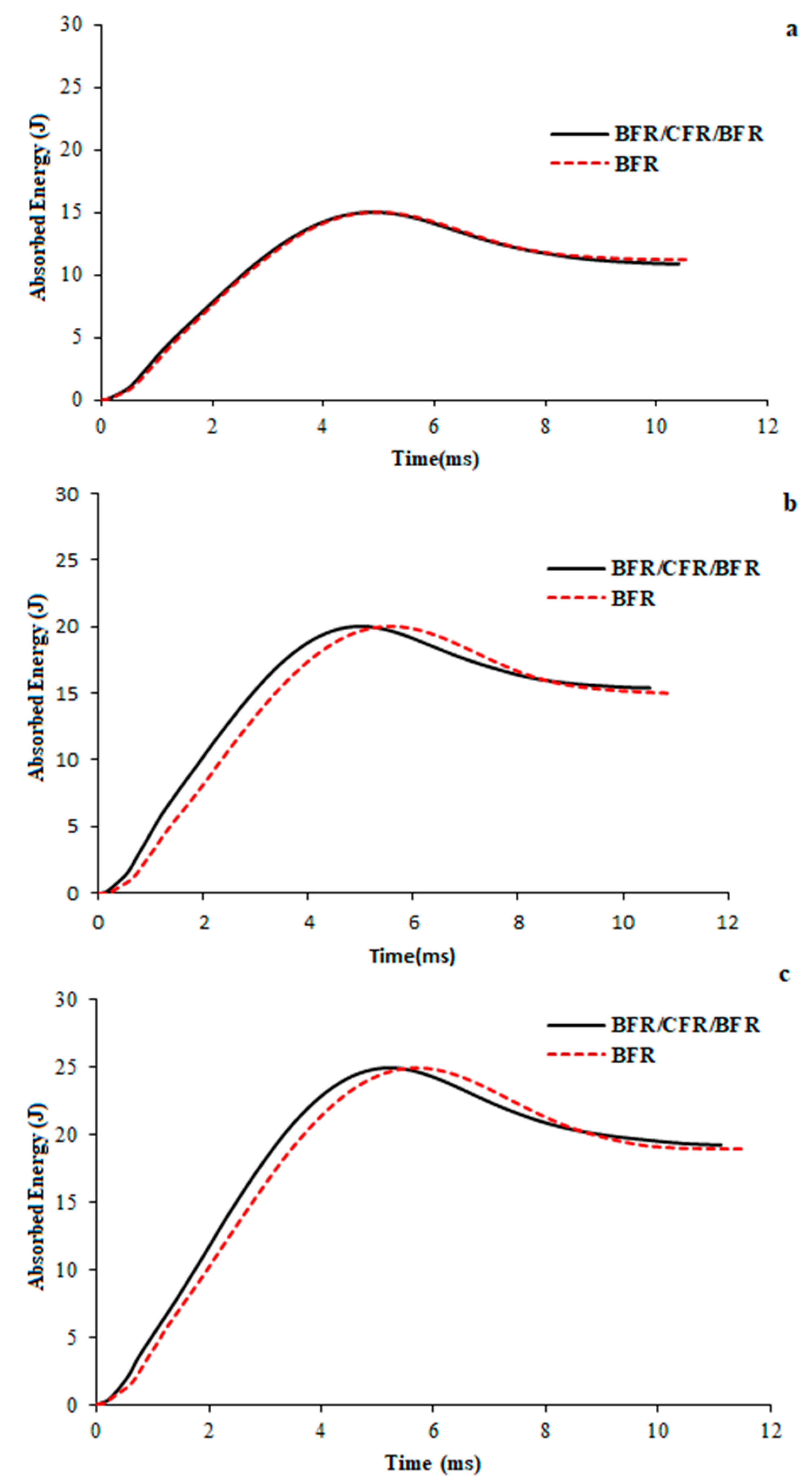
The energy–time graphs in Figure 6 are presented for different impact energy levels. Observing the energy–time plots at each level, it is obviously seen that the rebound energy of the BFR/CFR/BFR hybrid samples is higher than that of the BFR samples. This suggests that the intermediate CFR layers increase the overall stiffness of the hybrid samples. However, the greater displacement occurring during the impact period is interpreted to account for the higher energy absorption seen in the BFR sample. The increase in displacement indicates that more bending occurs along the impact axis in the BFR samples during impact loading. This increased deflection is thought to cause the formation and propagation of delamination between the composite layers around the impact zone. Consequently, it can be concluded that the expansion and progression of the delamination area contribute to the higher impact energy absorption in the BFR samples. The mean values of maximum load, displacement, absorbed energy, and rebound energy for three different energy levels, along with their standard deviations, are reported below.
Figure 6.
Energy–time graphs of BFR and BFR/CFR/BFR hybrid samples at 15 J (a), 20 J (b), and 25 J (c).
4. Surface Damage Propagation Analysis
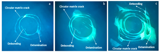
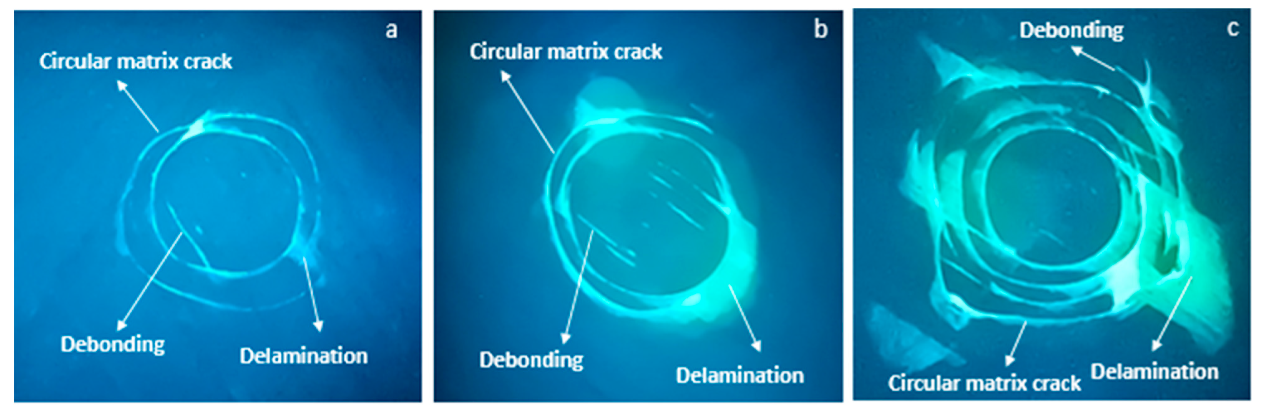
Liquid penetrant and UV light applications were performed to detect surface damage resulting from LVI tests at 15 J, 20 J, and 25 J on BFR and BFR/CFR/BFR hybrid tubes. Surface damage areas resulting from these conditions were then quantitatively determined using an image processing technique. The primary purpose of using liquid penetrant and UV light methods is to obtain high-resolution images of the damage areas to allow for the identification of detailed damage types. Figure 7a–c show the damage zones on the impact surfaces of BFR samples exposed to impact at 15 J, 20 J, and 25 J after the application of liquid penetrant and UV light techniques. When the impact damage area of the BFR sample at 15 J is inspected in Figure 7a, circular matrix cracks and delamination are detected in the central region surrounded by circular cracks. It is interpreted that the delamination damage develops between the concentric circular matrix cracks and propagates towards the outermost crack. As shown in Figure 7b, at 20 J, it is observed that the delamination extends along the junction of adjacent circular matrix cracks. Furthermore, an increase in delamination is detected in the central regions of these circular crack formations. In Figure 7c, an increase in the number of circular matrix cracks is observed at 25 J. Delamination is found to develop between these expanding circular cracks, propagating outward from the outermost crack. It is also interpreted that the delamination occurs along the fiber direction between the circular matrix cracks, with delamination acting as the initiating mechanism.
Figure 7.
Surface damage images of BFR composite samples with penetration at 15 J (a), 20 J (b), and 25 J (c).
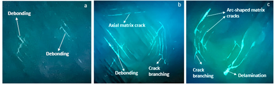
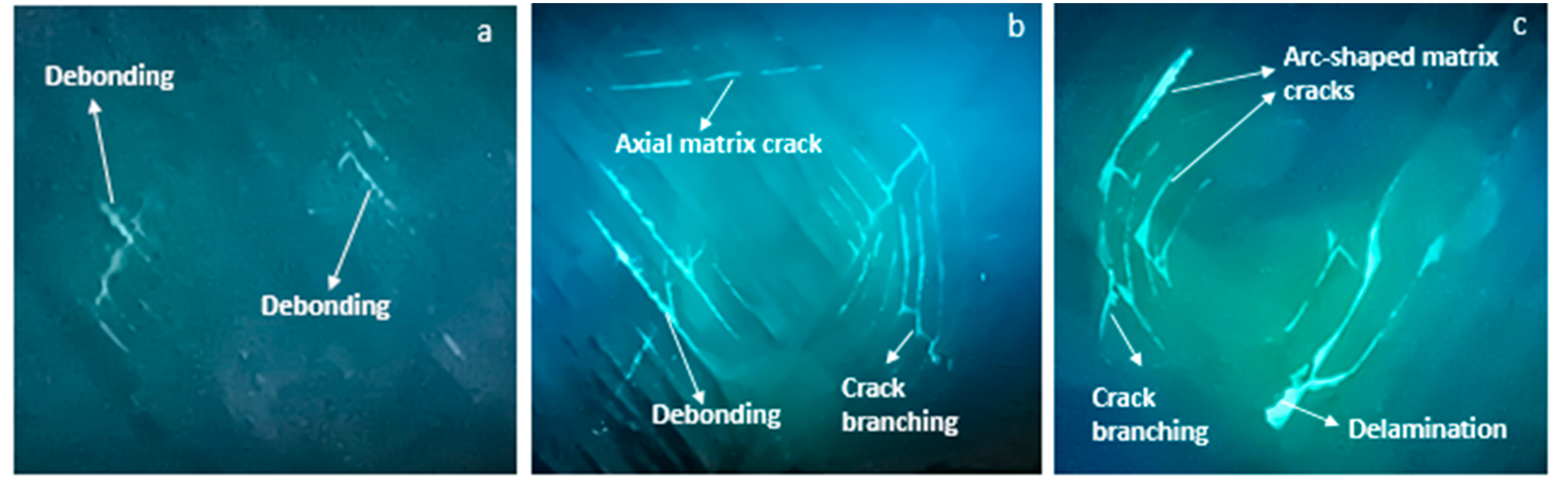
Figure 8a–c show the damage zones formed on the impact surfaces of BFR/CFR/BFR hybrid composite tubes at impact energies of 15 J, 20 J, and 25 J, respectively, after the application of liquid penetrant and UV light techniques. At 15 J, it appears that debonding damage is the main factor triggering the branching of cracks in the damaged area of the surface. At 20 J, the extent of debonding increased within the impact region, accompanied by the formation of axial matrix cracks and evidence of crack branching, as shown in Figure 8b. At 25 J, arc-shaped matrix cracks and more pronounced crack branching were observed in the impact zone, as presented in Figure 8c. Delamination was found to initiate at the tips of these branched cracks due to the interaction between matrix cracking and debonding. The UV-light-illuminated penetrant images further enhanced the visibility of the damaged regions and enabled accurate quantification of the affected surface areas. The corresponding surface damage areas for the BFR/CFR/BFR hybrid samples are presented in the graph below. As shown in Figure 7 and Figure 8, a comparison of surface damage in BFR and BFR/CFR/BFR hybrid samples reveals distinct dominant damage mechanisms. In BFR samples, circular matrix cracks and delamination are the primary damage types, while in BFR/CFR/BFR samples debonding and matrix cracks appear to be the more prevalent damage types. Figure 8 shows that for BFR composites, circular matrix cracks propagate by expanding with increasing impact energy and delamination propagates outward along these cracks. In the BFR/CFR/BFR hybrid samples, debonding and arc-shaped matrix cracks were observed to develop progressively with increasing impact energy. The primary factor influencing the change in dominant damage type seems to be the increase in displacement. In the BFR samples, the greater displacement associated with higher impact energy is considered to lead to the formation and growth of circular matrix cracks and delamination. In the hybrid composites, the intermediate CFR reinforcement increased the overall stiffness of the composite pipe, leading to a reduction in displacement at each impact energy level, as shown in Figure 5. However, due to the higher stiffness of the CFR layers compared to the BFR layers, the upper BFR layers were exposed to crushing under higher impact energies, which influenced the dominant failure mechanism. In other words, the intermediate CFR layers can be considered to provide partial underpinning to the upper BFR layers against the applied impact force (Figure 4). Consequently, crushing damage is primarily concentrated in the upper BFR layers. Microscopic images in Figure 10d,f show radial cracks in the upper layers resulting from crushing. It can also be seen from Figure 8b,c that radial cracks exhibit damage progression through crack branching. In addition to these observations, it can be inferred from the images of surface damage that the contact area of the hemispherical impactor has increased as a result of the rise in energy levels.
Figure 8.
Surface damage images of BFR/CFR/BFR hybrid composite samples with penetration at 15 J (a), 20 J (b), and 25 J (c).
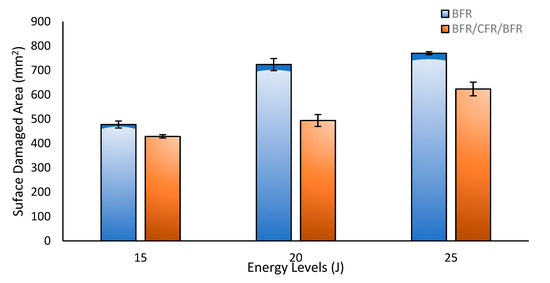
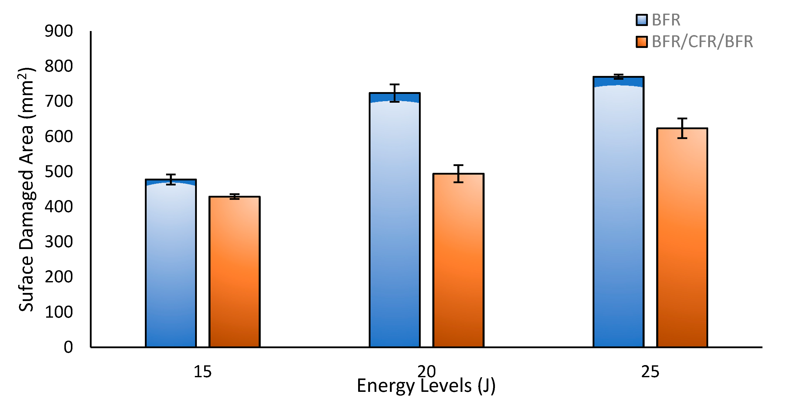
Figure 9 and Table 3 show the surface damage areas in the impact region of BFR and BFR/CFR/BFR hybrid composites obtained using the image processing method, including standard deviations. As shown in Figure 9, the surface damage areas of BFR samples at 15 J, 20 J, and 25 J are larger than those of BFR/CFR/BFR hybrid samples. The graph shows that the difference in surface damage area between BFR composites and BFR/CFR/BFR hybrid composites occurs most at 20 J. This demonstrates that the CFR fiber reinforcement layer is highly effective at this energy level. However, at 25 J, the increase in displacement with rising impact energy is thought to reduce the effectiveness of the CFR reinforcement layer. As a result of LVI tests performed at different energy levels, surface damage was analyzed using image processing, allowing for quantitative measurement.
Figure 9.
Areas of surface damage in the impact zone of BFR and BFR/CFR/BFR hybrid composites.
Table 3.
Mean values of surface-damaged areas after image processing.
5. Intra-Layer and Inter-Layer Failure Analysis
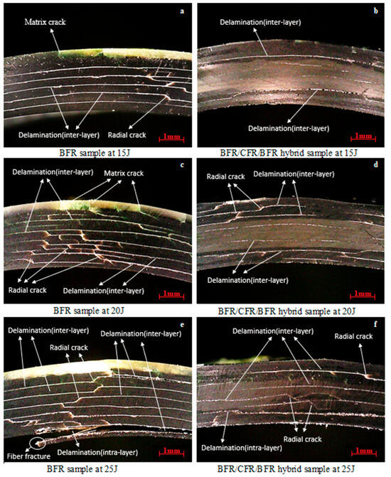
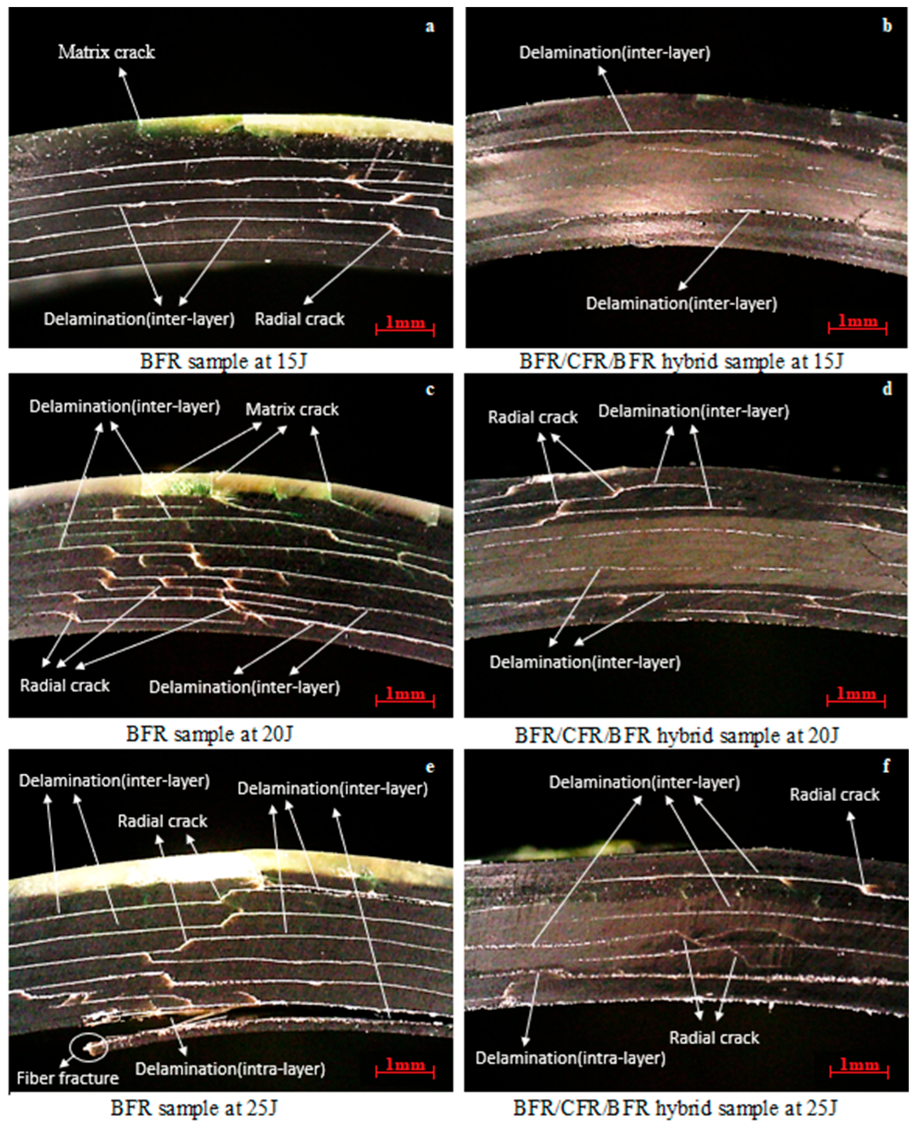
Micro-scale cross-sectional images showing the damage within the layer structures of the impact regions of BFR and BFR/CFR/BFR hybrid composite tubes exposed to low-velocity impacts at 15 J, 20 J, and 25 J are presented in Figure 10. In the micrograph at 15 J, presented in Figure 10a, micro-cracks were detected in the top layer of the BFR samples. Moving from the top layer to the lower layers, interlayer delamination damage was observed between successive layers of the BFR composites. In the middle layers, as shown in Figure 10a, radial cracks formed as a result of the merging of debonding propagating in the radial direction within the layer. In the micrograph of the BFR/CFR/BFR hybrid samples at the 15 J, introduced in Figure 10b, interlayer delamination was identified at the interface between the second BFR layer (constituting the upper ±2 layers) and the top CFR layer (constituting the middle ±2 layers). Similarly, delamination damage was observed at the interface between the lower BFR and the upper CFR layers, which together form the lower ±2 layers. The formation of interlayer delamination damage is believed to result primarily from global bending in the impact region analogous to three-point bending as well as from local bending that increases with the extent of delamination. Moreover, the difference in elastic modulus between the BFR and CFR composite layers can be considered one of the key factors contributing to delamination in the BFR/CFR/BFR hybrid composites at the 15 J. Although the elastic modulus of the BFR layers forming the upper two plies is relatively low during impact, the high modulus of the CFR layers in the middle section provides structural support to the upper BFR layers. Therefore, this supporting role is illustrated in Figure 5, where the CFR layers exert a reinforcing effect on the upper BFR layers. However, it can be inferred that the global bending induced by the impact is effective across the ±4 layers constituting the BFR/CFR structure. Consequently, the interlayer delamination observed at the BFR/CFR interface is considered to play a significant role in its formation. Additionally, the increase in displacement and local bending may contribute to the formation of interlayer delamination at the interface between the middle ±2 CFR and the lower ±2 BFR layers. Both global and local bending generate compressive stresses in the upper layers and tensile stresses in the lower layers.
Figure 10.
Micro-scale cross-sectional images of the damage of BFR samples at 15 J (a), 20 J (c), 25 J (e) and BFR/CFR/BFR hybrid samples at 15 J (b), 20 J (d), and 25 J (f).
These compressive and tensile stresses can act as initiating factors in the formation of interlayer delamination. Micrographs of the BFR and BFR/CFR/BFR hybrid samples are presented in Figure 10c,d. With rising impact energy, the extent of interlayer delamination in the BFR samples increased. As shown in Figure 10c, a noticeable rise in radial cracks was accompanied by an increase in micro-cracks within the upper layer. In Figure 10d, it was observed that in the BFR/CFR/BFR hybrid samples, radial cracks developed alongside delamination in the upper BFR layers when the impact energy reached 20 J. However, no radial cracks were detected in the lower BFR layers. This finding suggests that the formation of radial cracks in the upper BFR layers is attributed to the high elastic modulus of the intermediate CFR layers, which provide a supporting effect and cause the impact load to crush the upper BFR layers. As the impact energy increases, global bending also intensifies due to the rise in displacement. Consequently, interlayer delamination damage is considered to occur between the CFR layers. Figure 10e,f present the microstructural damage images of the BFR and BFR/CFR/BFR hybrid samples at 25 J, respectively. At this energy level, interlayer delamination was observed in the BFR samples, similar to the damage observed at 15 J and 20 J. It is believed that as the energy level rises, the interlayer delamination damage becomes less effective in absorbing energy, leading to the multiplication and propagation of radial cracks throughout nearly all layers during damage progression. Furthermore, these propagating radial cracks are thought to induce intra-layer delamination in the lower layers, eventually resulting in fiber breakage, as shown in Figure 10e. In the damage images of the BFR/CFR/BFR hybrid samples at 25 J, shown in Figure 10f, interlayer delamination was observed throughout all layers. Interlayer delamination originating from the CFR layers, which was not evident at 15 J, first appeared at 20 J. At 25 J, this delamination within the CFR layers became more extensive and widespread. Additionally, as seen in Figure 10f, radial cracks were detected in the CFR layers at 25 J, whereas no such cracks were observed at 15 J or 20 J. Overall, it can be concluded that in the BFR composites, interlayer delamination and radial crack progressively increase from 15 J to 25 J. At 25 J, damage progression results in intra-layer delamination and fiber breakage.
6. Statistical Analysis
In the conducted study, one-way ANOVA statistical analyses were performed to determine the significance of the differences between the experimental results obtained from LVI tests and the results derived from image processing analysis of surface damage. The results of the one-way ANOVA statistical analysis of the experiments are presented in Table 4 and Table 5. In the experiments conducted, the dependent variables are maximum load, displacement, and absorbed energy. The independent variables are the impact energy levels (15 J, 20 J, 25 J) and the hybrid configuration. The sample size is 18 for three replicates for each sample and energy level. The degrees of freedom for Factor (DF = 1), Error (DF = 4), and Total (DF = 5) have been shown in Table 4 and Table 5, together with the corresponding sums of squares (SS), mean squares (MS), F-values, and p-values.
Table 4.
One-way ANOVA analysis of LVI test results for 15 J, 20 J, and 25 J.
Table 5.
One-way ANOVA analysis of imaging processes results for 15 J, 20 J, and 25 J.
In Table 4 and Table 5, the most important parameter is the p-value. When the p-value is less than 0.05, the experimental results indicate statistical significance. When examining the p-values in the tables, it is observed that all experimental results are less than 0.05. The R2 value is important for determining how strong the relationship is between energy variations and the energy levels of the experimental results obtained from LVI and image processing analyses. At all energy levels, the R2 values for the LVI tests indicate a strong statistical relationship, while a very strong statistical relationship is observed at the 25 J energy level, as shown in Table 4. In the image processing analysis results, a strong statistical relationship is observed at the 15 J energy level, while a very strong statistical relationship is observed at the 20 J and 25 J energy levels, as shown in Table 5. The measurement uncertainty for the key performance parameters—maximum load, maximum time, and absorbed energy—remained within the range of approximately 0.2% to 2.8% (CoV). For maximum displacement, CoV values range from 4% to 11.8%. Generally, CoV values fall within the range of 0.2–11.8%. While it is generally accepted that CoV values below 5% indicate very low measurement uncertainty, it is noted that in tests of composites, if the CoV is below 15% according to the literature, the repeatability of the tests is considered acceptable and the experimental variation is low [47,48,49,50,51]. Based on a general evaluation, it was concluded that in BFR/CFR/BFR hybrid composites, the CFR layer limits the increase in displacement and reduces the CoV values and that as the energy level increases, the load-bearing behavior of the carbon layers reduces deflection.
7. Conclusions
LVI tests were conducted on ±[55°]6 BFR and ±[55°]6 BFR/CFR/BFR hybrid samples at 15 J, 20 J, and 25 J. In accordance with the three energy levels, the effects of CFR reinforcement hybridized with BFR samples on impact load, displacement, energy absorption, and rebound energy were analyzed using the corresponding graphs. Damage development on the impact surfaces was examined and quantified using liquid penetrant with image processing techniques. Furthermore, the influences of CFR hybridization on variations in the dominant damage mechanisms were determined. The key findings of the study are summarized below.
In all composite samples, impact force, contact time, and displacement increased with rising impact energy. The maximum impact loads of the BFR/CFR/BFR hybrid samples were higher than those of the BFR samples at all energy levels, while their displacement values were consistently lower. Additionally, the rebound energy was greater in the hybrid composites. These results indicate that CFR-reinforced hybrid samples exhibit stiffer overall behavior compared to pure BFR samples. Examination of the impact surfaces using liquid penetrant revealed that in BFR samples, delamination occurred alongside concentric ring-shaped matrix cracks, with debonding detected in the inner regions of the rings. In the BFR/CFR/BFR hybrid samples, arc-shaped matrix cracks and branched debonding were observed in the damaged areas. Quantitative comparison of the surface damage areas indicated that the BFR samples consistently exhibited larger damage areas than the hybrid samples at all energy levels. In the damaged regions of BFR samples, the dominant damage types were radial cracks and delamination, particularly at 15 J, 20 J, and 25 J. In contrast, for BFR/CFR/BFR hybrid samples, delamination was the primary damage mode.
When the study is assessed as a whole, it has demonstrated that the hybridization of the middle layers of basalt-fiber-reinforced FWC tubes with CFR results in a change in damage modes, thereby delaying damage progression. The integration of the liquid penetration process—used in industrial applications to monitor the development of surface damage—with image processing techniques has, as a new method, facilitated the monitoring and tracking of damage development through numerical values.
In this study, the focus was on investigating the impact behavior and the development and evolution of damage modes in BFR and BFR/CFR/BFR FWC hybrid tubes at the 15 J, 20 J, and 25 J energy levels where the intermediate layer consists of CFR. In future studies, the scope of the research will be expanded by investigating low-velocity impact responses and the formation, development, and evolution of damage modes in hybrid configurations with different fiber reinforcements, winding angles, and geometries.
Funding
This study was supported by the Scientific Research Projects (BAP) Coordination Office at Selçuk University under project number 26601145.
Institutional Review Board Statement
Not applicable.
Informed Consent Statement
Not applicable.
Data Availability Statement
The original contributions presented in this study are included in the article. Further inquiries can be directed to the corresponding author.
Acknowledgments
The low-velocity impact (LVI) tests were performed at the Mechanical Engineering Department with Laboratory of Konya Technical University.
Conflicts of Interest
The authors declare no conflicts of interest.
Abbreviations
The following abbreviations are used in this manuscript:
| FWC | Filament Wound Composite |
| LVI | Low-velocity impact |
| BFR | Basalt Fiber Reinforcement |
| CFR | Carbon Fiber Reinforcement |
| GFR | Glass Fiber Reinforcement |
| CoV | Coefficient of Variation |
References
- Prabhakar, M.M.; Rajini, N.; Ayrilmis, N.; Mayandi, K.; Siengchin, S.; Senthilkumar, K.; Karthikeyan, S.; Ismail, S.O. An overview of burst, buckling, durability and corrosion analysis of lightweight FRP composite pipes and their applicability. Compos. Struct. 2019, 230, 111419. [Google Scholar] [CrossRef] [Scilit]
- Özbek, Ö.; Doğan, N.F.; Bozkurt, Ö.Y. An experimental investigation on lateral crushing response of glass/carbon intraply hybrid filament wound composite pipes. J. Braz. Soc. Mech. Sci. Eng. 2020, 42, 389. [Google Scholar] [CrossRef] [Scilit]
- Zhu, L.; Sun, B.; Hu, H.; Gu, B. Constitutive equations of basalt filament tows under quasi-static and high strain rate tension. Mater. Sci. Eng. A 2010, 527, 3245–3252. [Google Scholar] [CrossRef] [Scilit]
- Avci, A.; Şahin, Ö.S.; Tarakçioğlu, N. Fatigue behavior of surface cracked filament wound pipes with high tangential strength in corrosive environment. Compos. Part A Appl. Sci. Manuf. 2007, 38, 1192–1199. [Google Scholar] [CrossRef] [Scilit]
- Purnomo, H.; Soemardi, T.P.; Budiono, H.D.; Wibowo, H.B.; Ibadi, M. The Filament Winding Method’s Finishing Process Impact on Highfidelity Specimens: Homogenity of Density, Fiber Volume Fraction, Outer Surface Roughness and Tensile Strength. East.-Eur. J. Enterp. Technol. 2023, 126, 43. [Google Scholar] [CrossRef] [Scilit]
- Kang, C.; Zhan, J.; Ye, S.; Liu, Z.; Guo, J.; Deng, B.; Chen, Z. Void stability process window and parametric optimization for filament-wound composite riser. Polym. Compos. 2024, 45, 5590–5606. [Google Scholar] [CrossRef] [Scilit]
- Sambayi, P.M.K.; Heyns, P.S. Effects of multiple post cure cycles on properties of composite carbon fibre and epoxy materials. J. Compos. Mater. 2023, 57, 2467–2481. [Google Scholar] [CrossRef] [Scilit]
- Hiremath, V.; Singh, M.; Shukla, D.K. Effect of post curing temperature on viscoelastic and flexural properties of epoxy/alumina polymer nanocomposites. Procedia Eng. 2014, 97, 479–487. [Google Scholar] [CrossRef] [Scilit][Green Version]
- Stephen, C.; Shivamurthy, B.; Mohan, M.; Mourad, A.-H.I.; Selvam, R.; Thimmappa, B. Low velocity impact behavior of fabric reinforced polymer composites—A review. Eng. Sci. 2022, 18, 75–97. [Google Scholar] [CrossRef] [Scilit]
- Vasudevan, A.; Senthil Kumaran, S.; Naresh, K.; Velmurugan, R. Layer-wise damage prediction in carbon/Kevlar/S-glass/E-glass fibre reinforced epoxy hybrid composites under low-velocity impact loading using advanced 3D computed tomography. Int. J. Crashworthiness 2020, 25, 9–23. [Google Scholar] [CrossRef] [Scilit]
- Karamooz, M.R.; Rahmani, H.; Khosravi, H. Hybrid effects of basalt and kevlar fibers on low-velocity impact behavior of epoxy-based composites. Fibers Polym. 2020, 21, 2590–2598. [Google Scholar] [CrossRef] [Scilit]
- Wang, L.; Ma, W.; Deng, L.; Liu, S.; Yang, T. Mechanical model and mechanical property analysis of fibre-reinforced hybrid composite pipes. Mar. Struct. 2023, 89, 103396. [Google Scholar] [CrossRef] [Scilit]
- Chen, D.; Xiao, S.; Yang, B.; Yang, G.; Zhu, T.; Wang, M.; Zhang, Z. Axial crushing response of carbon/glass hybrid composite tubes: An experimental and multi-scale computational study. Compos. Struct. 2022, 294, 115640. [Google Scholar] [CrossRef] [Scilit]
- Papa, I.; Ricciardi, M.R.; Calzolari, A.; Langella, A.; Tirillò, J.; Sarasini, F.; Lopresto, V. Mechanical behavior and damage degree of hybrid glass/carbon composites at low temperature. Polym. Compos. 2021, 42, 2432–2444. [Google Scholar] [CrossRef] [Scilit]
- Demirci, M.T.; Şahin, Ö.S. Effect of oil pressure upon filament wound basalt/glass fibers hybrid polymer based composite pipes subjected to low velocity impact. Compos. Struct. 2022, 288, 115395. [Google Scholar] [CrossRef] [Scilit]
- Demirci, M.T.; Şahin, Ö.S. Low-velocity impact response and inspection of damage propagation for basalt fiber reinforced filament wound pipes. Polym. Compos. 2022, 43, 4626–4644. [Google Scholar] [CrossRef] [Scilit]
- Demirci, M.T.; Tarakçıoğlu, N.; Avcı, A.; Akdemir, A.; Demirci, I. Fracture toughness (Mode I) characterization of SiO2 nanoparticle filled basalt/epoxy filament wound composite ring with split-disk test method. Compos. Part B Eng. 2017, 119, 114–124. [Google Scholar] [CrossRef] [Scilit]
- Sun, G.; Tong, S.; Chen, D.; Gong, Z.; Li, Q. Mechanical properties of hybrid composites reinforced by carbon and basalt fibers. Int. J. Mech. Sci. 2018, 148, 636–651. [Google Scholar] [CrossRef] [Scilit]
- Meng, Q.; Wang, Z. Modeling analysis of fiber hybridization in hybrid glass/carbon composites under high-velocity impact. Polym. Compos. 2017, 38, 2536–2543. [Google Scholar] [CrossRef] [Scilit]
- Demirci, M.T. Low velocity impact and fracture characterization of SiO2 nanoparticles filled basalt fiber reinforced composite tubes. J. Compos. Mater. 2020, 54, 3415–3433. [Google Scholar] [CrossRef] [Scilit]
- Manikandan, V.; Jappes, J.W.; Kumar, S.S.; Amuthakkannan, P. Investigation of the effect of surface modifications on the mechanical properties of basalt fibre reinforced polymer composites. Compos. Part B Eng. 2012, 43, 812–818. [Google Scholar] [CrossRef] [Scilit]
- Sfarra, S.; Ibarra-Castanedo, C.; Santulli, C.; Paoletti, A.; Paoletti, D.; Sarasini, F.; Bendada, A.; Maldague, X. Falling weight impacted glass and basalt fibre woven composites inspected using non-destructive techniques. Compos. Part B Eng. 2013, 45, 601–608. [Google Scholar] [CrossRef] [Scilit]
- Martens, M.; Ellyin, F. Biaxial monotonic behavior of a multidirectional glass fiber epoxy pipe. Compos. Part A Appl. Sci. Manuf. 2000, 31, 1001–1014. [Google Scholar] [CrossRef] [Scilit]
- Hosur, M.; Adbullah, M.; Jeelani, S. Studies on the low-velocity impact response of woven hybrid composites. Compos. Struct. 2005, 67, 253–262. [Google Scholar] [CrossRef] [Scilit]
- Sayer, M.; Bektaş, N.B.; Demir, E.; Çallioğlu, H. The effect of temperatures on hybrid composite laminates under impact loading. Compos. Part B Eng. 2012, 43, 2152–2160. [Google Scholar] [CrossRef] [Scilit]
- Jusoh, M.; Santulli, C.; Yazid, M.; Hussein, N.; Ahmad, H. Effect of stacking sequence on the tensile and flexural properties of glass fibre epoxy composites hybridized with basalt, flax or jute fibres. Mater. Sci. Eng. Adv. Res. 2016, 1, 19–25. [Google Scholar] [CrossRef] [Scilit]
- Kumar, S.; Satapathy, B.K.; Patnaik, A. Thermo-mechanical correlations to erosion performance of short glass/carbon fiber reinforced vinyl ester resin hybrid composites. Comput. Mater. Sci. 2012, 60, 250–260. [Google Scholar] [CrossRef] [Scilit]
- Sinha, A.K.; Narang, H.K.; Bhattacharya, S. Mechanical properties of hybrid polymer composites: A review. J. Braz. Soc. Mech. Sci. Eng. 2020, 42, 431. [Google Scholar] [CrossRef] [Scilit]
- Dasari, S.; Saurabh, S.; Mahato, K.K.; Prusty, R.K.; Ray, B.C. Mechanical properties of glass/carbon inter-ply hybrid polymer composites at different in-situ temperatures. Mater. Today Proc. 2021, 39, 1192–1197. [Google Scholar] [CrossRef] [Scilit]
- Abolfazli, M.; Bazli, M.; Regmi, S.; Shakiba, M.; Ojo, C.O.; Rajabipour, A.; Hassanli, R.; Shahbazi, R.; Arashpour, M. Impact of Fire-Retardant coating on the residual compressive strength of hybrid Fibre-Reinforced polymer tubes exposed to elevated temperature. Compos. Part A Appl. Sci. Manuf. 2025, 193, 108831. [Google Scholar] [CrossRef] [Scilit]
- Pai, Y.; Pai, K.D.; Kini, M.V. Effect of ageing conditions on the low velocity impact behavior and damage characteristics of aramid-basalt/epoxy hybrid interply composites. Eng. Fail. Anal. 2023, 152, 107492. [Google Scholar] [CrossRef] [Scilit]
- Nisini, E.; Santulli, C.; Liverani, A. Mechanical and impact characterization of hybrid composite laminates with carbon, basalt and flax fibres. Compos. Part B Eng. 2017, 127, 92–99. [Google Scholar] [CrossRef] [Scilit]
- Kumar, C.S.; Arumugam, V.; Santulli, C. Characterization of indentation damage resistance of hybrid composite laminates using acoustic emission monitoring. Compos. Part B Eng. 2017, 111, 165–178. [Google Scholar] [CrossRef] [Scilit]
- Amini, M.; Gazik, R.A.; Honarvar, F.; Montazeri, A. Analysis of failure mechanisms of degraded hybrid glass-carbon composites in acidic medium: Insights from acoustic emission analysis. Eng. Fail. Anal. 2022, 134, 106082. [Google Scholar] [CrossRef] [Scilit]
- Rajan, B.G.; Padmanabhan, S.; Ganesh, R.L.; Chandana, K.M.; Lavanya, E. Low velocity impact analysis of carbon/glass/epoxy hybrid composite pipes. Mater. Today Proc. 2021, 47, 4181–4188. [Google Scholar] [CrossRef] [Scilit]
- Gemi, L. Investigation of the effect of stacking sequence on low velocity impact response and damage formation in hybrid composite pipes under internal pressure. A comparative study. Compos. Part B Eng. 2018, 153, 217–232. [Google Scholar] [CrossRef] [Scilit]
- Shi, L.; Yang, H.; Wu, Z.; Peng, L.; Ni, Q.; Li, Q. Effect of fiber layout on low-velocity impact response of intralaminar hybrid carbon/glass fiber braided composite pipes under internal pressure. Thin-Walled Struct. 2024, 198, 111711. [Google Scholar] [CrossRef] [Scilit]
- Demirci, M.T.; Tarakçıoğlu, N.; Avcı, A.; Erkendirci, Ö.F. Fracture toughness of filament wound BFR and GFR arc shaped specimens with Charpy impact test method. Compos. Part B Eng. 2014, 66, 7–14. [Google Scholar] [CrossRef] [Scilit]
- ASTM D7136/D7136M-15; Standard Test Method for Measuring the Damage Resistance of a Fiber-Reinforced Polymer Matrix Composite to a Drop-Weight Impact Event. ASTM International: West Conshohocken, PA, USA, 2020.
- ASTM D2584-18; Standard Test Method for Ignition Loss of Cured Reinforced Resins. ASTM International: West Conshohocken, PA, USA, 2026.
- Kaynak, C.; Mat, O. Uniaxial fatigue behavior of filament-wound glass-fiber/epoxy composite tubes. Compos. Sci. Technol. 2001, 61, 1833–1840. [Google Scholar] [CrossRef] [Scilit]
- Wolodko, J.D. Biaxial Fatigue and Leakage Characteristics of Fiber Reinforced Composite Tubes; University of Alberta National Library of Canada: Ottawa, ON, Canada, 1999. [Google Scholar]
- Meijer, G.; Ellyin, F. A failure envelope for ±60 filament wound glass fibre reinforced epoxy tubulars. Compos. Part A Appl. Sci. Manuf. 2008, 39, 555–564. [Google Scholar] [CrossRef] [Scilit]
- Demirci, I. Effect of hydraulic-oil aging, GNP reinforcement, and drilling strategy on thermomechanical drilling damage and barely visible drilling damage formation in aramid/Nomex honeycomb sandwich composites. Mater. Today Commun. 2026, 55, 115854. [Google Scholar] [CrossRef] [Scilit]
- Maziz, A.; Tarfaoui, M.; Gemi, L.; Rechak, S.; Nachtane, M. A progressive damage model for pressurized filament-wound hybrid composite pipe under low-velocity impact. Compos. Struct. 2021, 276, 114520. [Google Scholar] [CrossRef] [Scilit]
- Farhood, N.H.; Karuppanan, S.; Ya, H.H.; Sultan, M. Experimental investigation on the effects of glass fiber hybridization on the low-velocity impact response of filament-wound carbon-based composite pipes. Polym. Polym. Compos. 2021, 29, 829–841. [Google Scholar] [CrossRef] [Scilit]
- Tiwari, S.; Lee, J.; Khan, M.F.; Park, N. Statistical Variability and Lower-Tail Performance Assessment of Tensile Properties in Flax, Jute, and Carbon Fiber Composite Laminates. Polymers 2026, 18, 1746. [Google Scholar] [CrossRef] [Scilit] [PubMed]
- Correia, J.R.; Keller, T.; Knippers, J.; Mottram, J.T.; Paulotto, C.; Sena-Cruz, J.; Ascione, L. Design of Fibre-Polymer Composite Structures: Commentary to European Technical Specification CEN/TS 19101: 2022; CRC Press: Boca Raton, FL, USA, 2025. [Google Scholar]
- Amsc, N.; Cmps, A.A. Composite Materials Handbook. Polymer Matrix Composites Materials Usage, Design, and Analysis; SAE International: Warrendale, PA, USA, 2002. [Google Scholar]
- Onoue, S.; Ootsubo, M.; Nagakura, Y.; Sonoda, N. Carbon-Fiber-Reinforced Resin Composite Material. U.S. Patent Application 15/706,853, 4 January 2018. [Google Scholar]
- Martins, A.D.; Rosa, I.C.; Seruti, C.A.; Correia, J.R.; Teixeira, Â.P.; Silvestre, N.; Fernandes, C. Experimental investigation and uncertainty modelling of mechanical properties of a pultruded GFRP material. Compos. Sci. Technol. 2025, 269, 111214. [Google Scholar] [CrossRef] [Scilit]

Disclaimer/Publisher’s Note: The statements, opinions and data contained in all publications are solely those of the individual author(s) and contributor(s) and not of MDPI and/or the editor(s). MDPI and/or the editor(s) disclaim responsibility for any injury to people or property resulting from any ideas, methods, instructions or products referred to in the content. |
© 2026 by the author. Licensee MDPI, Basel, Switzerland. This article is an open access article distributed under the terms and conditions of the Creative Commons Attribution (CC BY) license.