


Abstract
In this work, a novel metamaterial unit cell based on a Modified Cross Dipole has been designed to switch a linear polarized beam into a cross-polarized one. In particular, the unit cell is constituted by two orthogonal wire layers separated by a phase compensator section. This unit cell has been employed for designing a 16 × 16 transmitarray antenna, allowing beamsteering with linear polarization. A 2-bit phase compensation approach has been chosen to improve the phase front of radiated waves. The transmitarray antenna has been fabricated and characterized, providing a measured realized gain of 21.6 dBi. The beamsteering of ±22° with a scan loss of −3 dB in both the E-plane and H-plane was obtained by shifting the primary radiator along the x- and y-axis. The results are in good agreement with the simulations.
1. Introduction
Metamaterials have been employed in the last decade with different aims, such as miniaturization, beamsteering, gain and bandwidth improvement, polarization control, and multi-band operation in the scenario of next-generation communications [1,2,3,4,5,6,7,8,9]. Their capability to manipulate the amplitude, phase, and polarization of electromagnetic waves through subwavelength engineered structures has made them a versatile platform for the development of high-performance microwave and millimeter-wave devices. Among this plethora of applications, metamaterial unit cells can be employed for the fabrication of efficient transmitarray antennas (TAs). TAs have attracted research attention in recent years thanks to their capability to steer beams, avoiding complex beamforming networks. Compared with conventional phased arrays, transmitarrays provide a favorable trade-off between antenna performance, fabrication complexity, and implementation cost, while maintaining a low-profile architecture. These characteristic aspects make them possible candidates for various applications such as satellite communications, radar systems, and 5G/6G wireless networks [2,3,4,5,6,7,8,10,11,12,13,14,15,16,17,18,19,20,21,22,23,24,25].
Typically, a transmitarray consists of multiple dielectric and metallic layers. The overall phase shifting needed for the phase compensation of the transmitted wave allows for front-plane formation. Each unit cell of the array introduces a specific phase delay to the incident wave, thus allowing the control/variation of the direction of the radiated beam. In this way, flexible capabilities of beam steering and multi-beam/high-gain radiation patterns are obtained [6,7,8,10,11]. Moreover, the absence of complex feeding networks significantly reduces feeding losses, particularly at high operating frequencies, contributing to an overall improvement in antenna efficiency.
Recent research has focused on improving the bandwidth, efficiency, and steering range of TAs. As an example, the use of reconfigurable elements, such as liquid crystals or PIN diodes, enables real-time beam steering, overcoming the drawbacks associated with fixed-phase designs [2,6]. Furthermore, transmitarrays leveraging metamaterials and higher-order resonators have been proposed to extend bandwidth and to improve the overall radiation efficiency [4,5,6,7,8,10,11,12,13,14,15,16,17,18,19,20,21,22,23,24,25]. At the same time, considerable efforts have been devoted to the optimization of unit cell geometries in order to achieve wide phase tuning ranges while maintaining high transmission coefficients and low insertion losses over the operating bandwidth. In the context of next-generation communication systems, beam steering at millimeter-wave (mmWave) frequencies is essential for mitigating path loss and ensuring reliable communication links, especially in dense urban environments. Several studies have demonstrated the effectiveness of transmitarrays for beam steering in the mmWave band, showcasing their potential for 5G and 6G applications [7,18,19,20,21,22,23,24,25].
In this work, a novel TA has been designed, fabricated, and experimentally validated. It is based on a Modified Cross Dipole with an Arc to guarantee asymmetric transmission. The proposed 16 × 16 unit cell TA achieves a measured gain , corresponding to a gain enhancement compared with the standalone primary antenna, while providing a high aperture efficiency with a footprint comparable to state-of-the-art solutions. Moreover, beam steering capabilities in both the x- and y-directions have been demonstrated for linear polarization, achieving a maximum measured steering angle of with a scan loss . The proposed TA represents a promising solution for high-gain 5G FR2-band communication systems, offering a compact and cost-effective alternative to conventional phased-array architectures. Future developments will focus on the integration of low-profile feeding antennas and electronically controlled switching circuits to enable fully reconfigurable beam steering without mechanical displacement.
2. Recall of Theory
2.1. Chiral Unit Cell
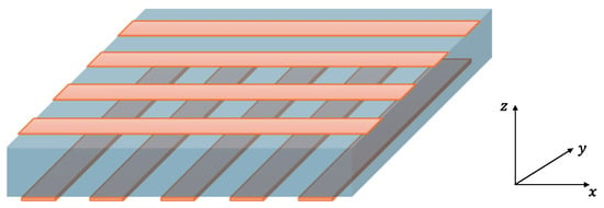
The simplest chiral unit cell is constituted by one dielectric substrate and two metallic layers. This structure allows the conversion of an arbitrarily polarized wave into a linearly polarized wave. More generally, to obtain asymmetric transmission, a chiral geometry must be considered, as reported in Figure 1 [14].
Figure 1.
Scheme of a chiral unit cell (metal parts in orange and dielectric substrate in blue).
Assuming this metamaterial is a homogeneous medium, the incident plane wave, propagating in the z-direction, can be written as [14]:
where is the wave vector, is the angular velocity, and and are the amplitudes in the and direction. The transmitted wave, after the interaction with the metamaterial, can be written as:
The Jones complex matrix allows for relating the amplitudes of the incident field with the amplitudes of the transmitted field as follows:
where the index indicates the forward direction. Applying the reciprocity theorem, it is possible to demonstrate that the T-matrix for backward propagation is:
Asymmetric transmission can be defined as the difference between the intensities of the forward and the backward propagation:
For linear polarization , the following asymmetric transmission relationship can be written:
In order to obtain asymmetric transmission, the unit cell must be designed to ensure that . This condition can be obtained by considering a three-dimensional chiral unit cell [14], and it is obtained in the case of Figure 1.
2.2. Intermediate Phase Control Layer
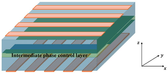
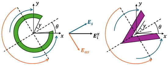
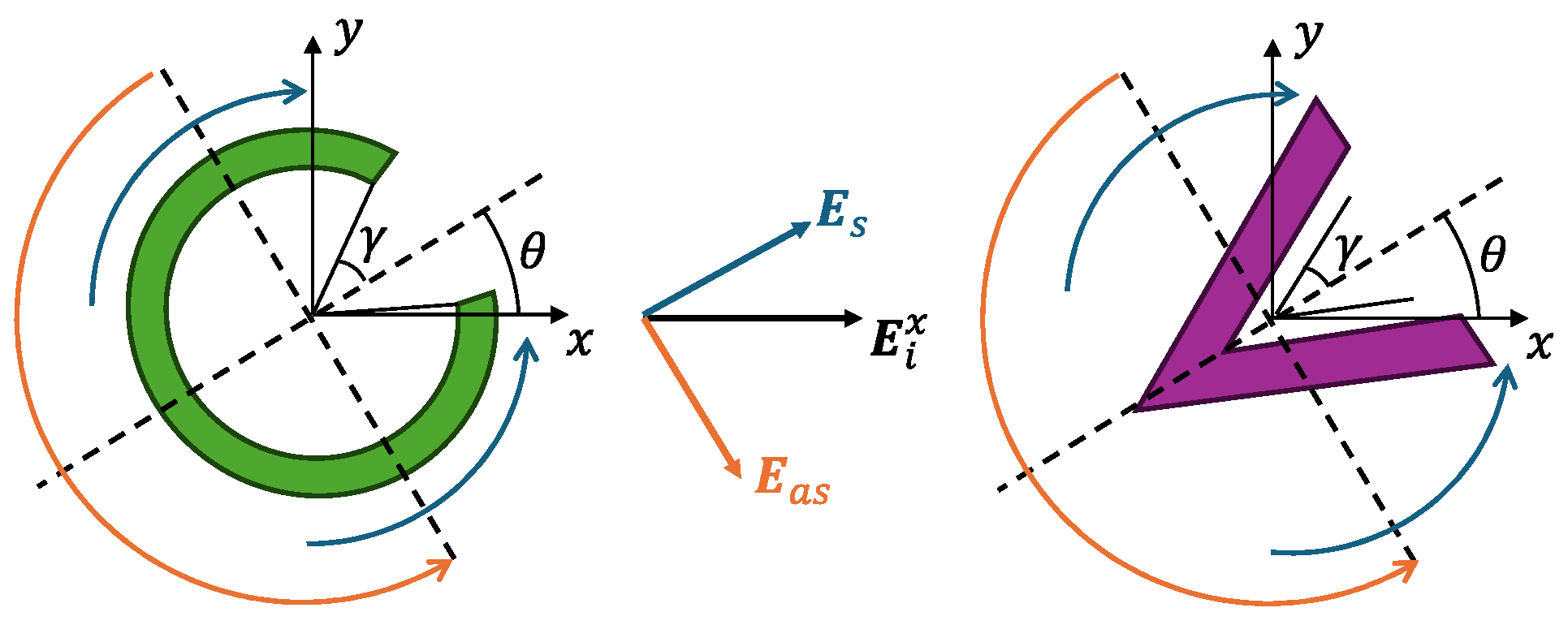
In order to obtain phase control covering the range , an intermediate phase control layer can be considered between the two metallic layers shown in Figure 1, thus obtaining the structure of Figure 2. To obtain the intermediate phase control layer, particular geometries are employed. Among the most common are the V-shape and the C-shape geometries, as shown in Figure 3. These metallic structures allow the decomposition of the normal incident wave into two components: the symmetric mode component and the antisymmetric mode component . In general, considering a -polarized incident wave with amplitude , symmetric and antisymmetric mode amplitudes , and phases , , the angle between the symmetry axis of the unit cell and the -axis, as in Figure 3, it is possible to obtain the transmitted, y-polarized wave according to [26]:
Figure 2.
Scheme of the complete structure allowing asymmetric transmission and the intermediate phase control layer (metal parts in orange, dielectric substrate in blue, intermediate phase control layer in green).
Figure 3.
Scheme of typical C-shaped and V-shaped intermediate unit cell layer for phase control, with symmetric mode and antisymmetric mode excitation of a -polarized incident wave .
Therefore, for , the maximum transmitted amplitude can be obtained.
To allow maximum asymmetric transmission, the unit cell geometry must support both symmetric and antisymmetric modes . Moreover, a suitable phase shift, in order to achieve the desired phase compensation layer, is required.
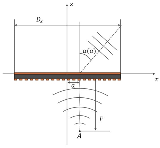
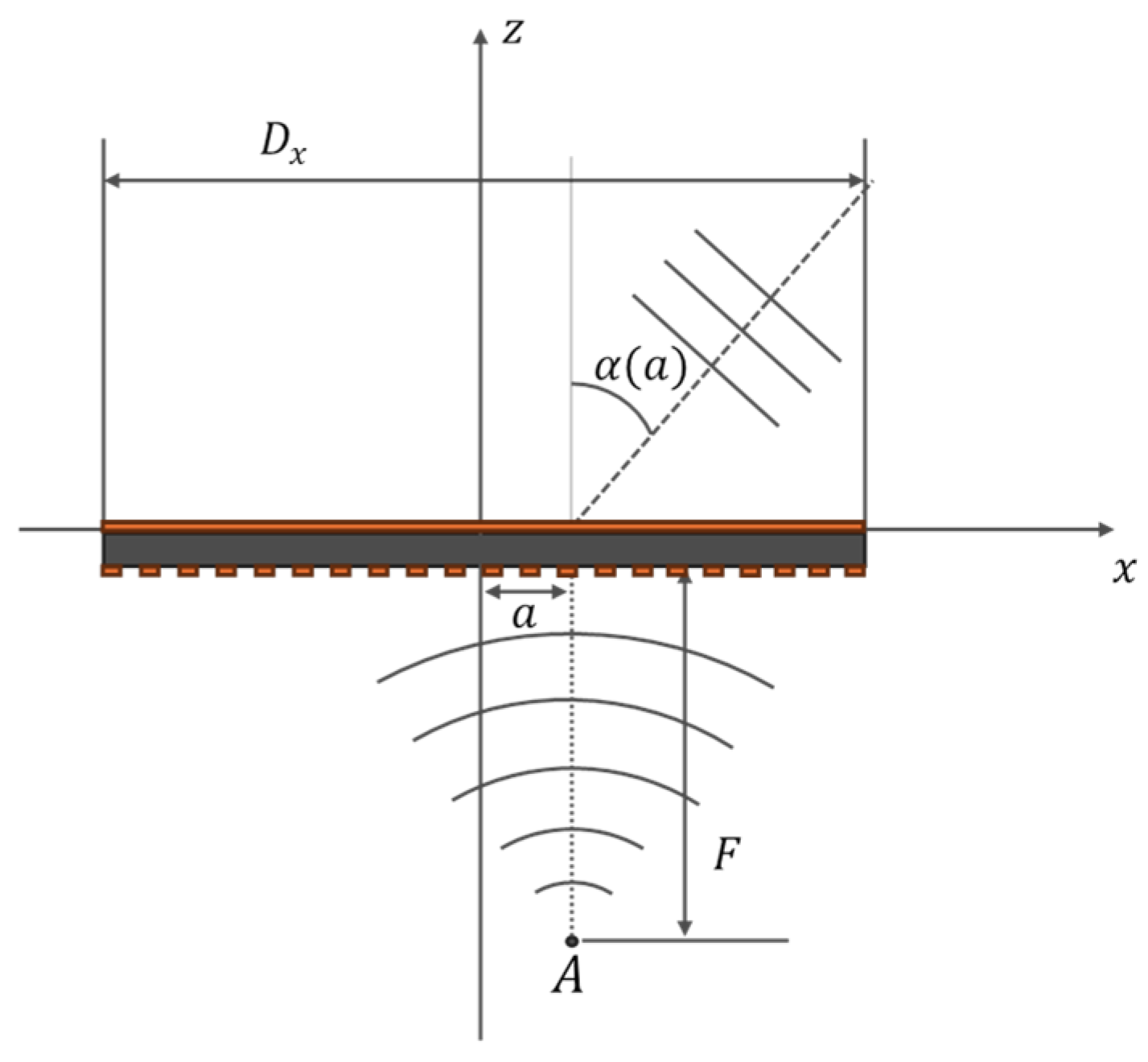
Figure 4 reports the scheme of a transmitarray (grey colored, with metallic parts in orange). The phase compensation distribution can be obtained by considering the following equation [11]:
where is the zenith beam direction, i.e., the z-axis direction, obtained when the primary antenna is placed at the focus ; and are the position of the unit cell; and is the focal distance. For broadside radiation, is chosen.
Figure 4.
Scheme of beamsteering by means of a transmitarray.
As is known from the literature, beamsteering can be obtained with transmitarrays, by shifting the primary antenna . The tilting angle depends on the primary antenna shifting , along the x or y directions, according to [15]:
3. Design of the Transmitarray Antenna
3.1. Unit Cell Design
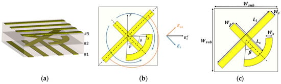
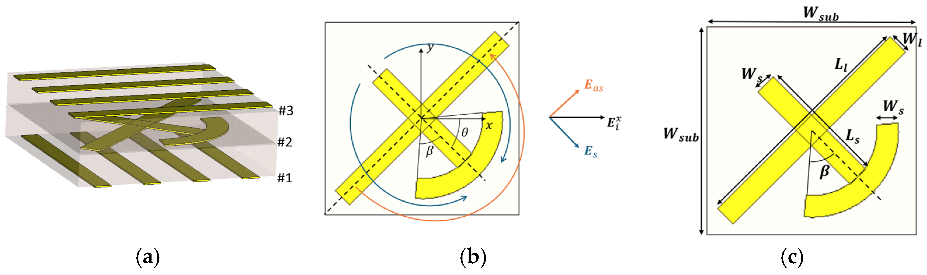
Starting from the theory of Section 2, the proposed unit cell is designed to operate at and consists of two dielectric substrates separated by three metallic layers, as illustrated in Figure 5a. The bottom and top metallic layers, labeled as #1 and #3, respectively, are formed by two identical gratings oriented orthogonally to each other. Together, these gratings constitute a Fabry–Pérot metasurface [14,16]. Their main function is to form a Fabry–Pérot resonant cavity that enhances the interaction between the incident electromagnetic wave and the intermediate metallic element, contributing to the control of the polarization-dependent transmission response.
Figure 5.
(a) Unit cell; (b) symmetric and antisymmetric mode excitation on the MCD-A; (c) geometrical parameters of the MCD-A.
The intermediate metallic layer, labeled as #2, consists of a Modified Cross Dipole with an Arc (MCD-A). The MCD-A element is rotated by an angle with respect to the -axis. This orientation produces a symmetric electromagnetic response along the direction and an asymmetric response along the orthogonal direction. According to Equation (7), this condition is required to maximize the transmitted-wave amplitude and to obtain the desired polarization-conversion mechanism.
In particular, the MCD-A geometry supports the simultaneous excitation of the symmetric and antisymmetric modes, denoted by and , respectively, as shown in Figure 5b. The two components are characterized by different transmission amplitudes and phases through the multilayer structure. By properly adjusting the geometrical parameters of the MCD-A element and the Fabry–Pérot cavity, the relative phase difference and amplitude balance between and can be accurately controlled. Their coherent superposition at the output produces the desired polarization state when the required amplitude ratio and relative phase are achieved. The outer gratings further enhance this mechanism through multiple reflections inside the cavity, increasing the interaction length and improving the overall transmission performance around the design frequency.
The main advantage of the proposed MCD-A unit cell over conventional C-shaped and V-shaped unit cells lies in the larger number of geometrical degrees of freedom available during the optimization process. In addition to the lengths and widths of the individual cross-dipole arms, both the length and width of the arc can be independently varied. These additional geometrical parameters provide further control over the effective inductive and capacitive behavior of the resonant element and allow a more accurate adjustment of its resonance frequency, modal coupling, impedance matching, and transmission phase.
Moreover, the cross-dipole and arc components influence the symmetric and antisymmetric modes in different ways. This provides greater flexibility in controlling the amplitude ratio and phase difference between the two modes without modifying the overall dimensions of the unit cell. Compared with simpler C- and V-shaped geometries, the MCD-A topology therefore enables a finer and more independent tuning of the electromagnetic response. This additional design flexibility is particularly useful for simultaneously achieving high transmission amplitude, the required phase condition, and efficient polarization conversion at the frequency . The described physical mechanism is also confirmed by the current distribution on the metallic elements of the unit cell.
The unit cell is a square with a side . For the design, the dielectric substrate Rogers RT/duroid 5880 ( ) was chosen with a commercial thickness and copper thickness The variation in the geometrical parameters, such as the cross dipole lengths and , the cross dipole widths and , and the angle of the arc , affects the phase shifting caused by the unit cell on the transmitted wave . The unit cell has been designed to provide scattering parameters with a phase step , in order to implement a 2-bit compensation. This phase quantization represents a good compromise between beamforming accuracy and implementation complexity, allowing the realization of efficient transmitarrays with a limited number of phase states. The optimized values are reported in Table 1.
Table 1.
Geometrical parameters employed in the design.
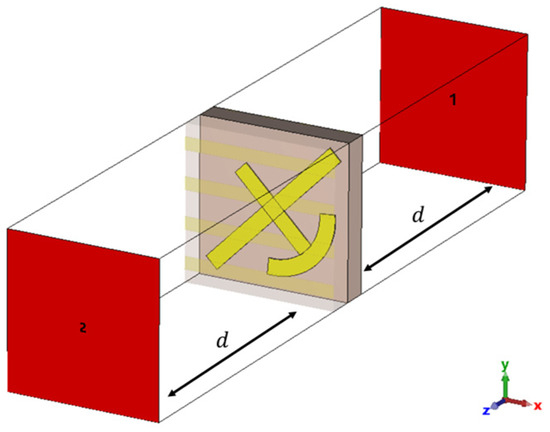
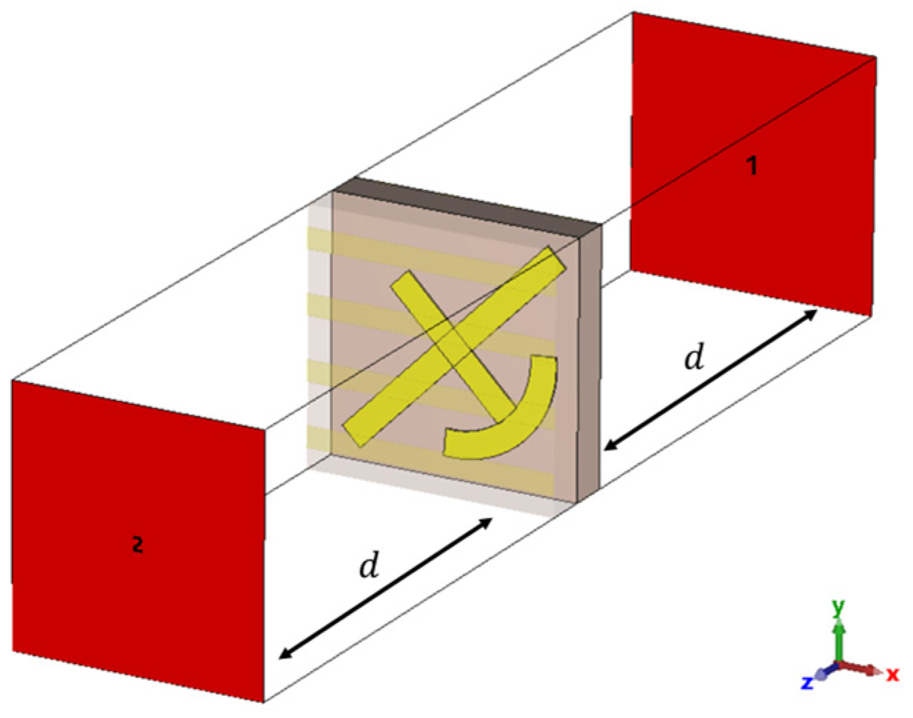
By considering the scheme in Figure 6, where the input (port 1) and the output (port 2) are Floquet ports with the de-embedding distance , the simulation of scattering parameters provides the phase change and the attenuation of the transmitted wave. The use of Floquet ports allows the electromagnetic response of an infinite periodic array to be accurately evaluated under plane-wave excitation, thus representing the actual operating conditions of the transmitarray unit cell. Floquet port 1 was excited with both -polarized and -polarized waves in order to verify the polarization selectivity and the polarization conversion of the unit cell. The transmitted wave is the -polarized wave, converted into an -polarized wave. The simulation was performed considering “unit cell” boundary conditions along the - and -axis, and “open” boundary conditions along the -axis.
Figure 6.
Unit cell excitation by Floquet ports in CST Microwave Studio with de-embedding at distance .
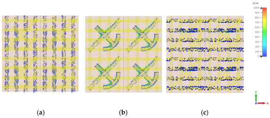
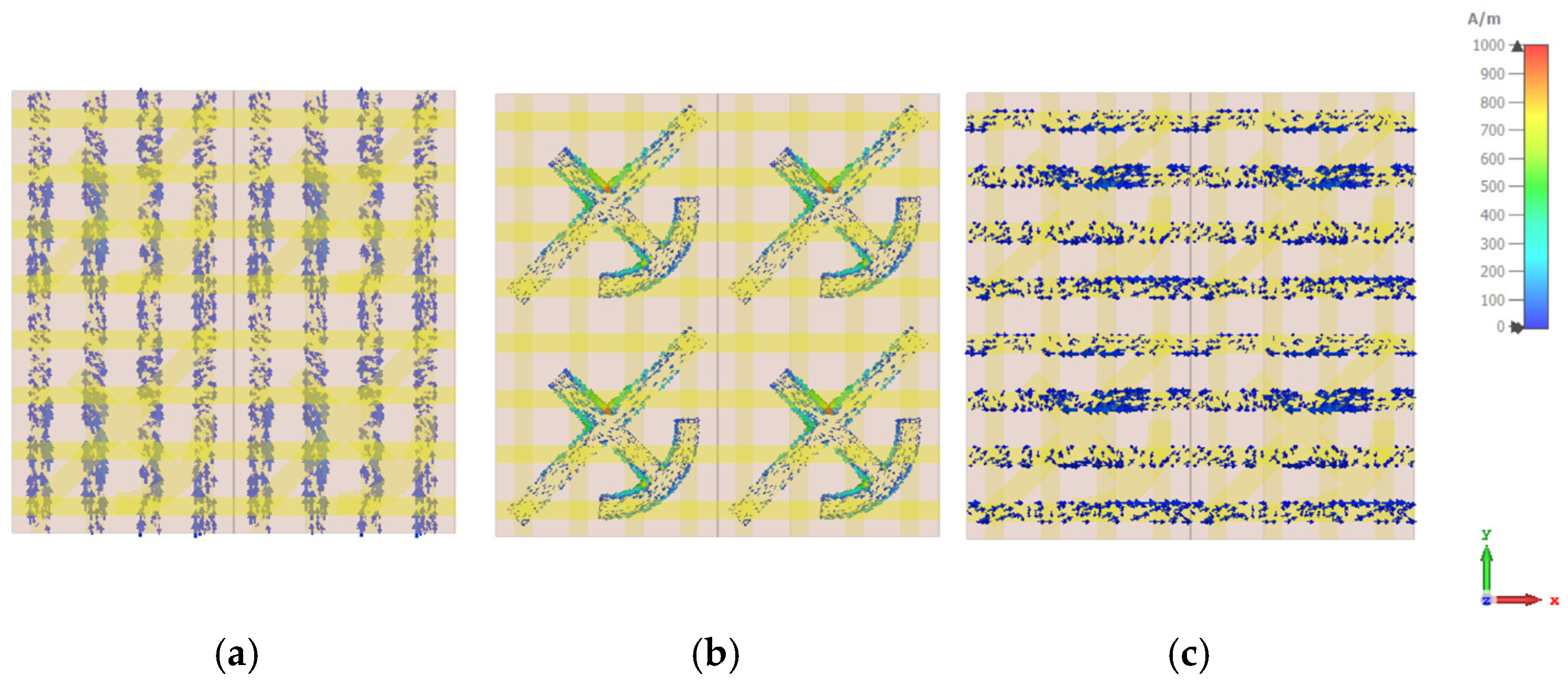
Figure 7 shows the current distribution of unit cell #1 when it is excited by a y-polarized incident wave. In particular, Figure 7a shows the distribution along the y-axis, parallel to the polarization of the incident wave; Figure 7b reports the distribution on the intermediate phase control layer, causing the phase compensation; Figure 7c shows the current distribution along the x-axis, confirming the polarization conversion.
Figure 7.
Current distribution of the unit cell #1 excited with a y-polarized incident wave: (a) bottom layer, (b) intermediate layer, (c) top layer.
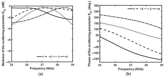
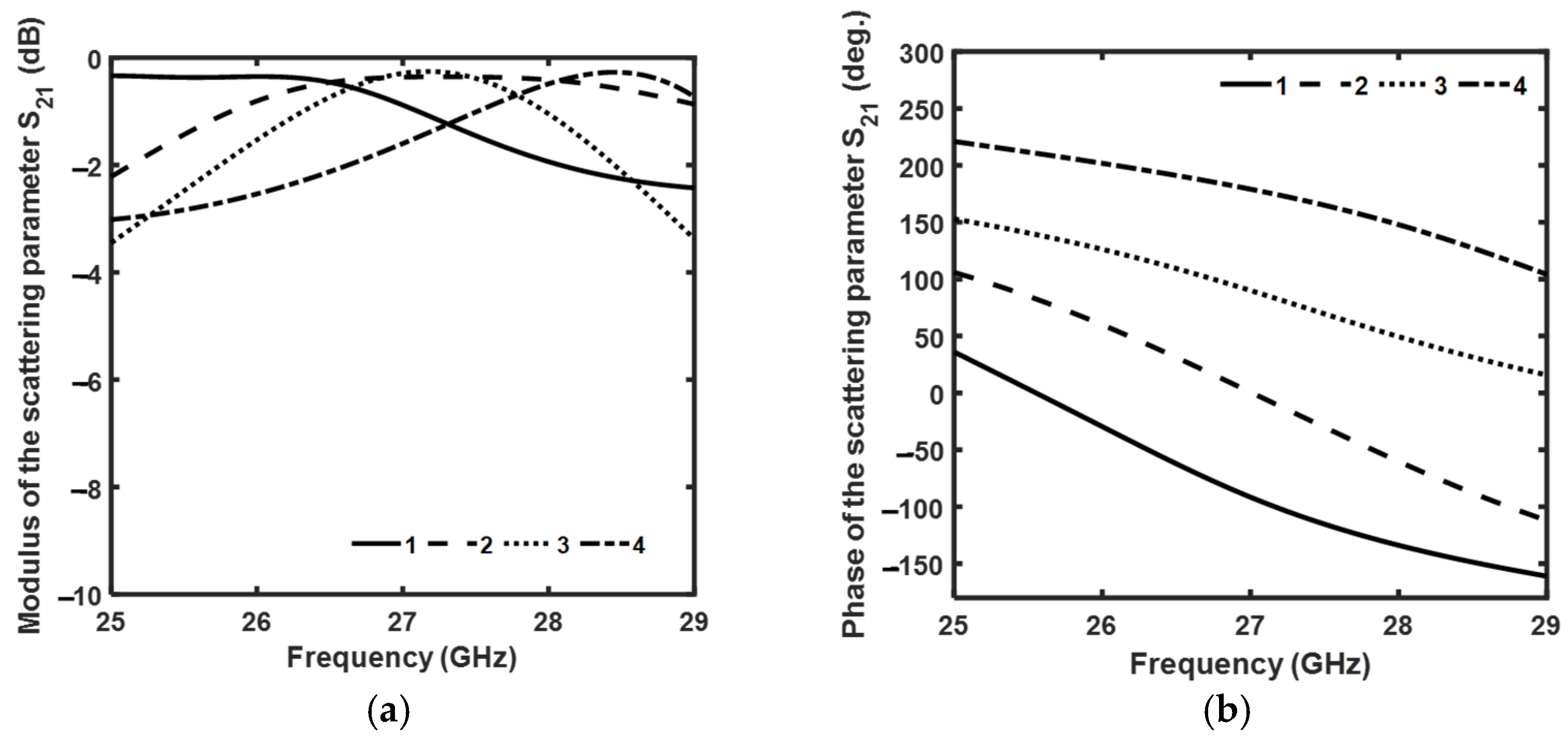
Figure 8a reports the simulated modulus and Figure 8b the simulated phase of the scattering parameters as a function of frequency for the four unit cells when excited with a planar incident wave. The evaluated refers to an input -polarized wave and a transmitted -polarized wave, . For the sake of readability, it has always been referred to as , being the only one considered in the work. In the frequency band , the four unit cells provide a quite constant phase step , while the modulus of the scattering parameters varies in the range in the same frequency band. The obtained results demonstrate that the proposed unit cells preserve the desired phase quantization over the entire operating bandwidth while maintaining low insertion loss, which is a key requirement for efficient transmitarray implementations.
Figure 8.
Simulated (a) modulus and (b) phase of the scattering parameters as a function of frequency for parallel planar excitation.
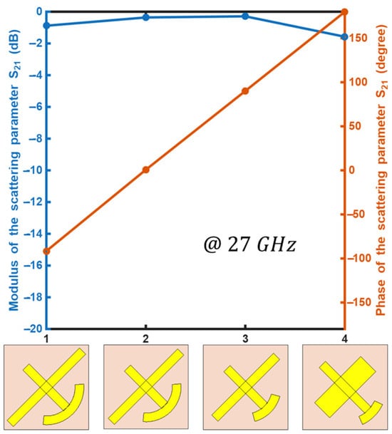
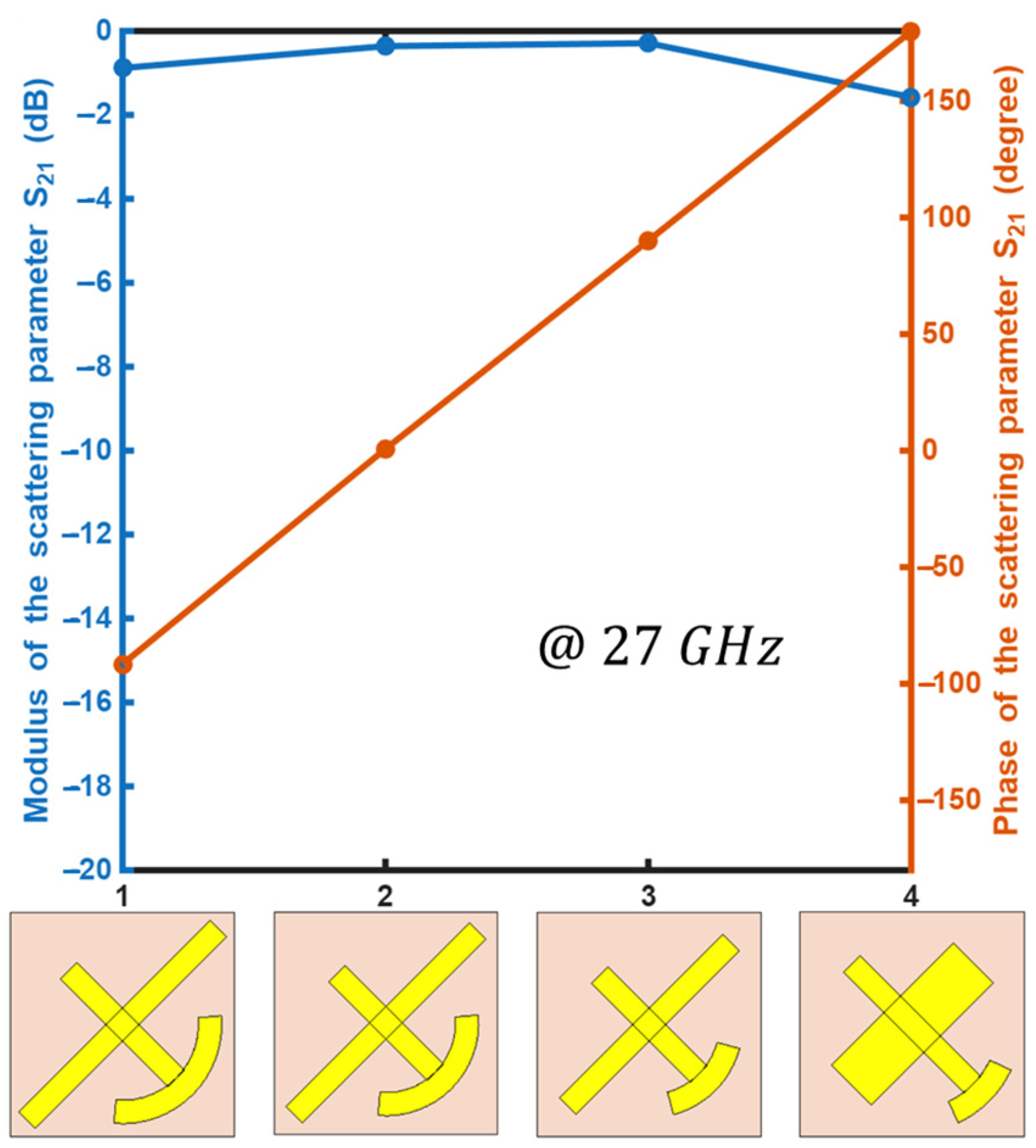
In particular, at the frequency as shown in Figure 9, the magnitude of the scattering parameters of the four unit cells is higher than and exhibits a flat behavior (blue curve); the phases (red curves) linearly increase with respect to the unit cell number, being for the intermediate cell numbers 1, 2, 3, and 4. The excellent agreement with the target phase values confirms the effectiveness of the proposed design methodology and validates the optimization procedure adopted for the unit cell geometry. Furthermore, the limited amplitude variation among the four phase states contributes to reducing aperture efficiency degradation when the unit cells are combined to form the complete transmitarray. The polarization conversion efficiency, defined as , for the four unit cells at frequency , is , , , and .
Figure 9.
Simulated modulus (blue line) and phase (red line) of the scattering parameters at frequency for the four unit cells.
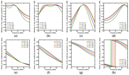
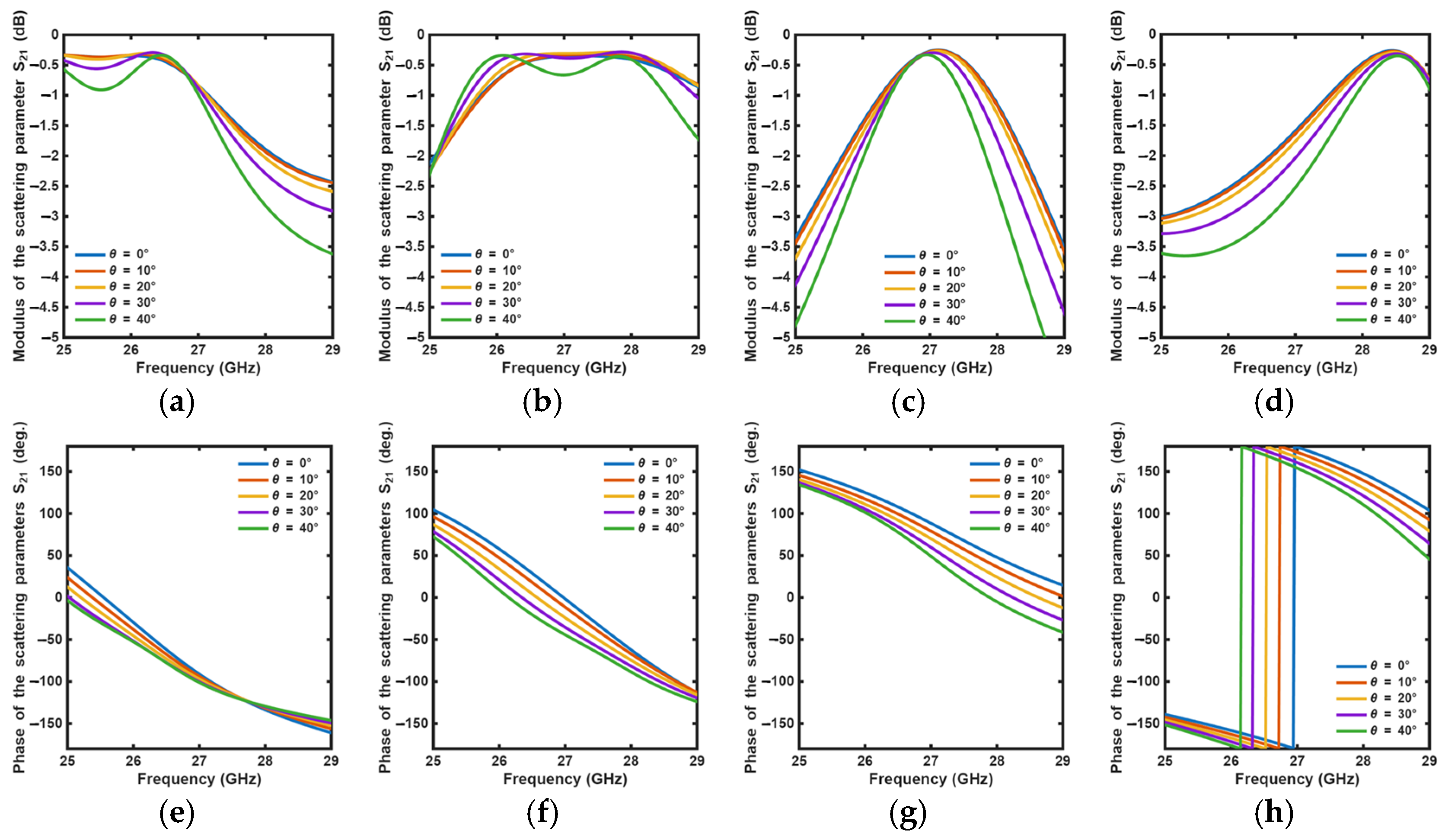
Figure 10 shows the simulated modulus and phase of scattering parameters as a function of the frequency of the four unit cells for different incident angles of the exciting planar wave. Similar results can be obtained for negative angles and for the other unit cells, also ensuring good transmission in case of planar incident waves with different incident angles. This behavior demonstrates that the proposed element is relatively insensitive to the angle of incidence within the investigated range, which is particularly advantageous in practical transmitarray configurations where the feed illuminates the aperture with different incidence angles depending on the element position. The obtained angular stability therefore contributes to preserving the overall radiation performance of the antenna over the entire aperture. The angular dependence of the transmission response is mainly related to the variation in the electromagnetic interaction between the incident wave and the metallic grids under oblique incidence. As the incidence angle increases, the orientation of the incident electric field with respect to the grids and the tangential component of the wave vector change, leading to a different excitation of the induced currents on the two orthogonal grids. As a consequence, both the amplitude and phase of the transmitted field, including the converted -polarized component, are modified with respect to the normal-incidence condition. This effect becomes increasingly significant at large incidence angles, for which the electromagnetic field interacts with the unit cell geometry under substantially different conditions. In the actual transmitarray configuration, the incident wave is also characterized by a finite beamwidth, so that the unit cells across the aperture are locally illuminated with different incidence angles and experience different incident field amplitudes and phases. Nevertheless, the nominal design of the unit cell is carried out under normal-incidence conditions, which are adopted as the reference condition for defining the required transmission phase and amplitude response.
Figure 10.
Simulated modulus of the scattering parameters as a function of frequency for different incident angles of the exciting planar wave, (a) unit cell 1, (b) unit cell 2, (c) unit cell 3, (d) unit cell 4, and simulated phase of the scattering parameters as a function of frequency: (e) unit cell 1, (f) unit cell 2, (g) unit cell 3, (h) unit cell 4 for different incident angles of the exciting planar wave.
3.2. Transmitarray Design
A 16 × 16 unit cell transmitarray has been designed, with a ratio , where is the focal distance and is the maximum dimension of the transmitarray, as reported in Figure 4. The overall aperture size has been selected as a compromise between achievable gain and fabrication complexity. Moreover, the selected ratio provides a good balance between spillover efficiency and phase aberrations, representing a common design choice for high-performance transmitarray antennas.
The dual ridge horn antenna SH4000 by Microwave Vision Group (MVG), working in the frequency range , has been employed as the primary feed. At , it provides a realized gain , a side lobe level , and a half-power beamwidth . The wide operating bandwidth of the horn antenna makes it suitable for the experimental characterization of the proposed transmitarray without introducing significant frequency-dependent distortions. Furthermore, its radiation pattern ensures an adequate illumination of the transmitarray aperture while limiting excessive spillover losses.
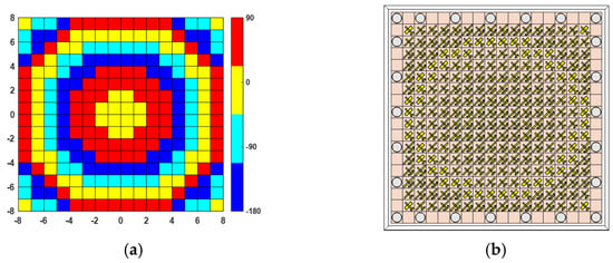
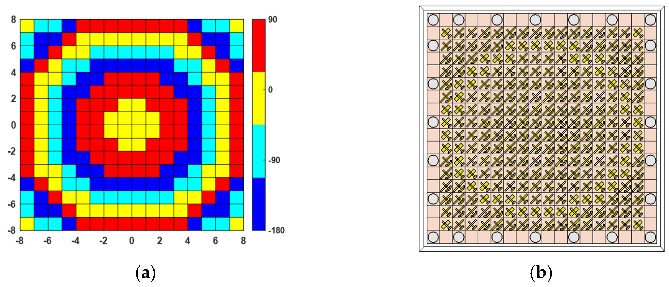
Figure 11 shows the 2-bit phase compensation pattern of the transmitarray, with the focal distance obtained by employing Equation (8). A monofocal phase distribution is considered in order to investigate beamsteering in both the E-plane and H-plane. The phase assigned to each unit cell is determined according to its position within the aperture so that the transmitted wavefront is properly compensated and redirected toward the desired direction. The colorimetric scale (red for 90°, yellow for 0°, cyan for −90°, and blue for −180°/180°) gives an efficient view of the phase change distribution. As expected for a 2-bit implementation, the phase profile is quantized into four discrete states while still closely approximating the ideal continuous phase distribution.
Figure 11.
(a) Monofocal phase compensation pattern for 2-bit compensation with focal distance ; (b) intermediate phase control layer based on the unit cells of Table 1.
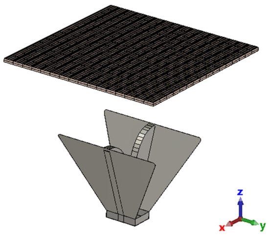
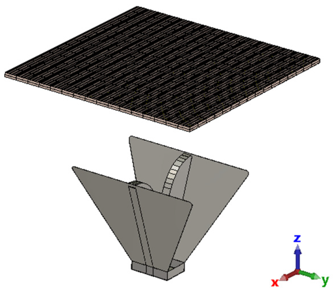
Figure 12 shows the 16 × 16 unit cell transmitarray with the feeding horn antenna placed in the focus, simulated in CST Microwave Studio. The complete numerical model includes both the feeding antenna and the transmitarray in order to account for their mutual electromagnetic interaction and to accurately predict the overall radiation performance of the proposed system. The full-wave simulation was performed considering “open” boundary conditions along the three axes.
Figure 12.
16 × 16 unit cell transmitarray with the feeding horn antenna.
4. Fabrication and Characterization
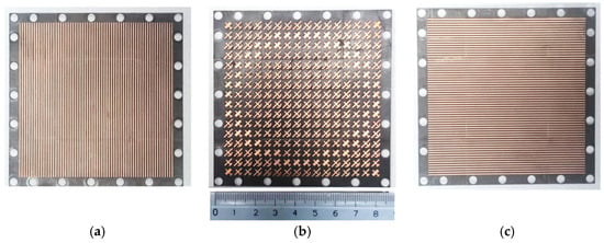
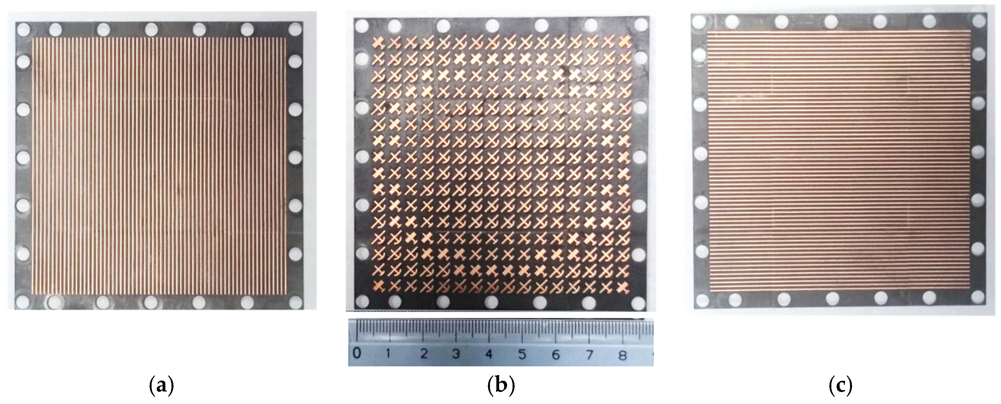
The transmitarray was constructed via the LPKF Protolaser U3 and assembled by means of dielectric screws. The use of a high-precision milling process allows the fabrication of the multilayer structure while preserving the dimensional accuracy required for the correct operation of the unit cells. Figure 13 shows the constructed prototype with the three metallic layers: (a) bottom layer, (b) intermediate phase control layer, (c) top layer.
Figure 13.
Constructed prototype: (a) bottom layer, (b) intermediate phase control layer, (c) top layer.
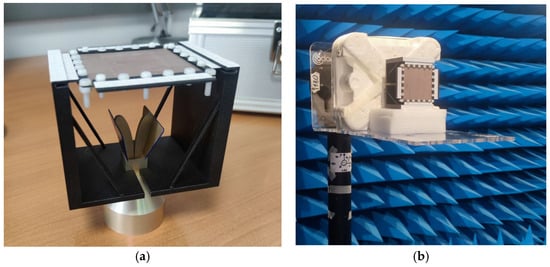
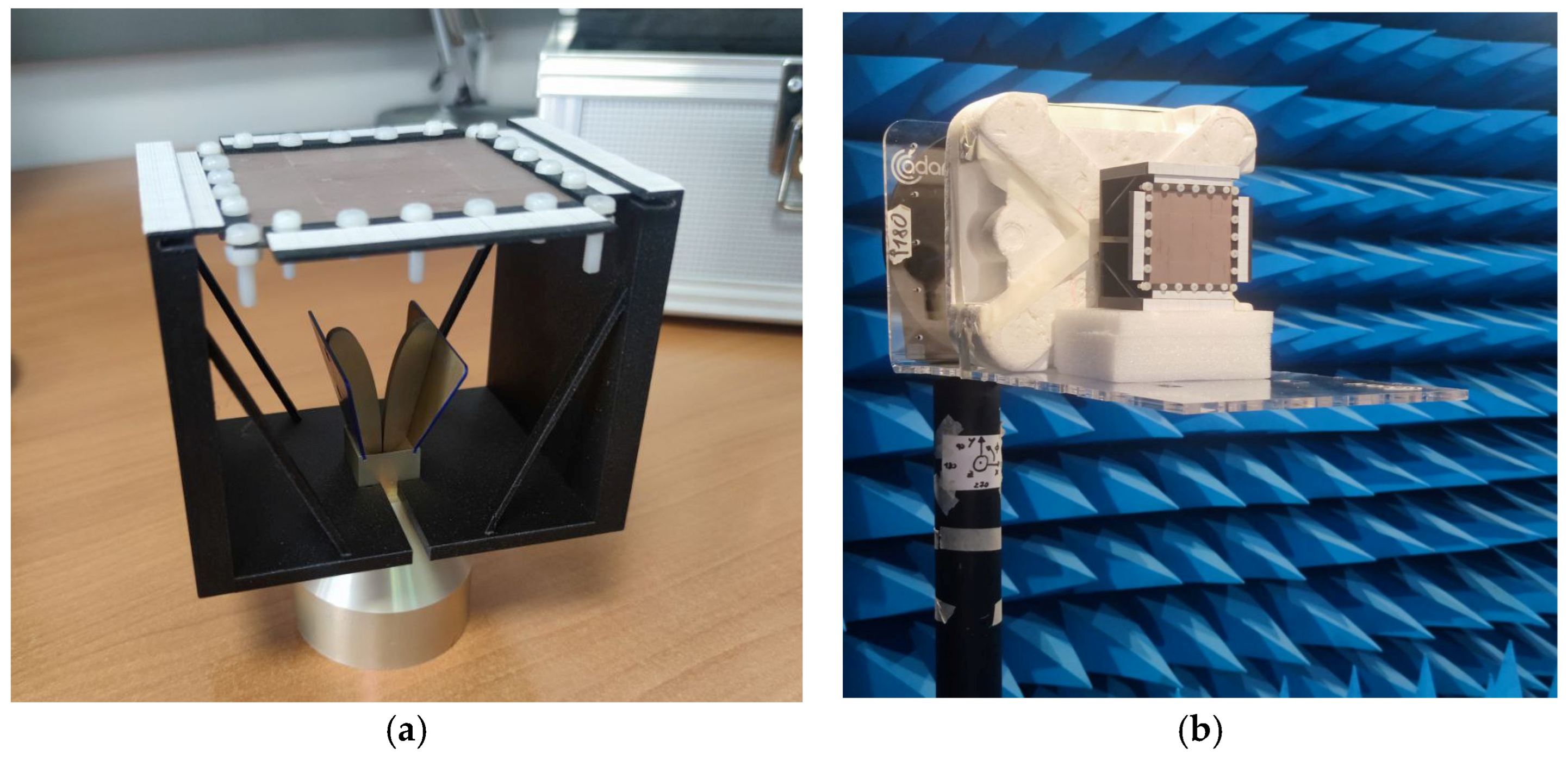
Figure 14a shows the constructed prototype. A 3D-printed support has been employed for maintaining the focal distance and providing the controlled shift in the feeding during the measurements. The dimensions of the horn antenna MVG SH4000 are 51.6 mm × 34 mm × 104.3 mm (H × W × L). The distance between the horn antenna and the transmitarray is 43 mm.
Figure 14.
(a) Constructed prototype; (b) characterization in an anechoic chamber.
The prototype has been characterized by employing the VNA Anritsu MS46122B in an anechoic chamber, as shown in Figure 14b.
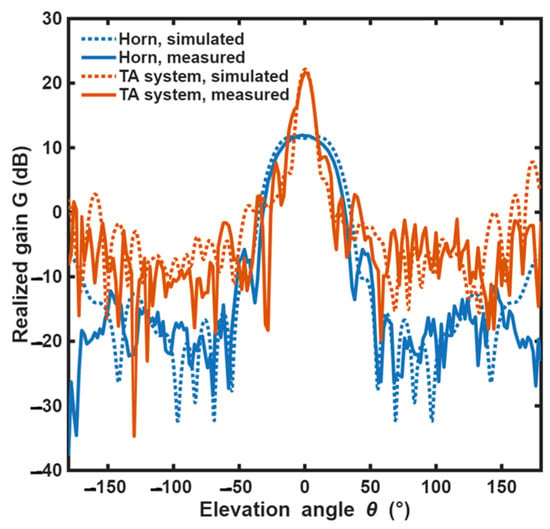
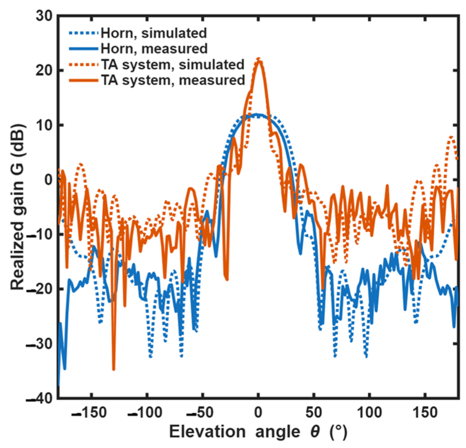
Figure 15 shows the realized gain measured (solid curves) and simulated (dotted curves) as a function of the elevation angle for the transmitarray system (red curves) and the pristine horn antenna (blue curves), for azimuth angle , at the frequency . In the broadside direction, the complete structure provides a simulated gain improvement with respect to the horn , a side lobe level , and a half power beamwidth . These results confirm the capability of the proposed transmitarray to transform the radiation pattern of the feeding antenna into a highly directive beam through the engineered phase compensation provided by the unit cells. It is worth noting how the is significantly reduced after transmission through the metamaterial, and the side lobe level is maintained. This behavior highlights the effectiveness of the proposed design in improving the directivity without introducing a significant degradation of the radiation pattern. Measured realized gain has been obtained, showing good agreement with the simulations.
Figure 15.
Measured (solid curves) and simulated (dotted curves) realized gain as a function of the elevation angle and for the azimuth angle for the transmitarray system (red curve) and the feeding horn antenna (blue curve).
The slight discrepancy between the simulated and measured results demonstrates the robustness of the proposed design and confirms the accuracy of the adopted electromagnetic model and fabrication process. The aperture efficiency of the transmitarray has been calculated following the formula , where is the physical area of the transmitarray and is the realized gain. The simulated aperture efficiency is , and the measured aperture efficiency is .
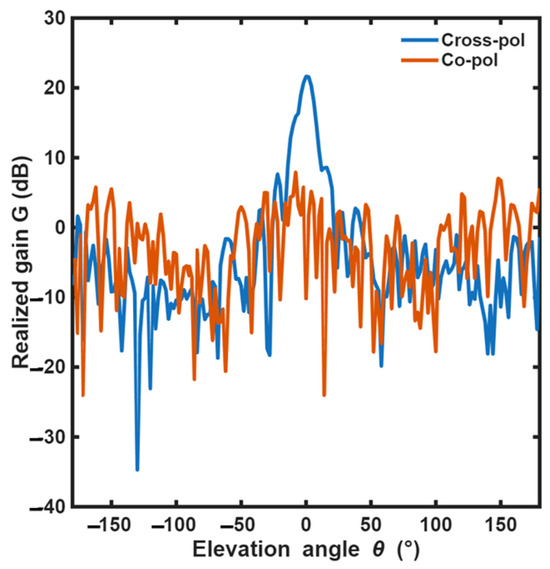
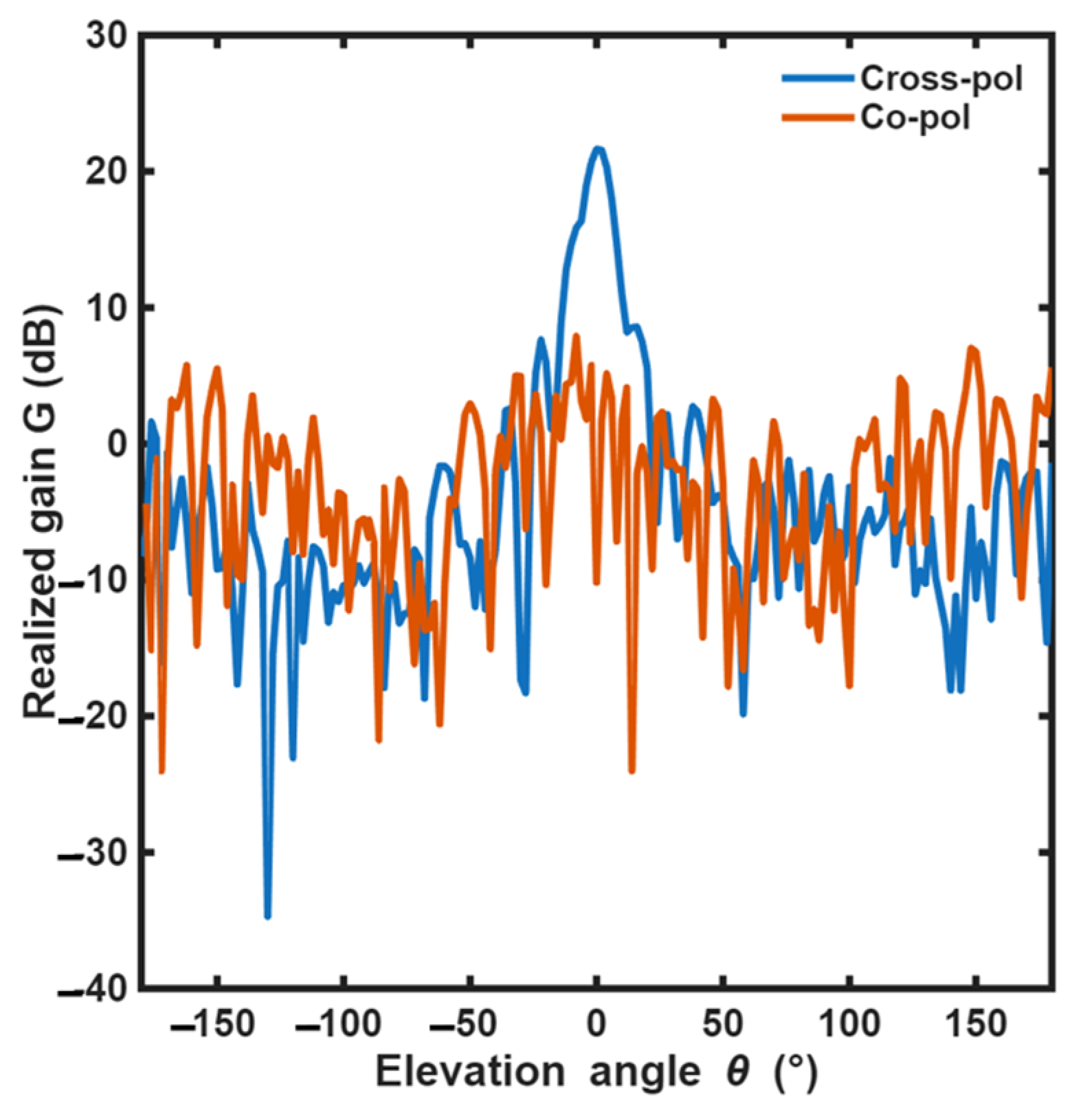
Figure 16 reports the measured realized gain as a function of the elevation angle for . The gain for the cross-polarized component is represented by the blue line and for the co-polarized component by the red line. It is evident that the proposed transmitarray is able to convert the linear polarization provided by the primary feed, i.e., the horn antenna, from the co-polarized component to the cross-polarized component.
Figure 16.
Measured realized gain as a function of the elevation angle for , cross-polarized component (blue line) and co-polarized component (red line).
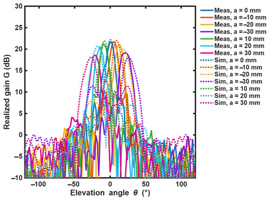
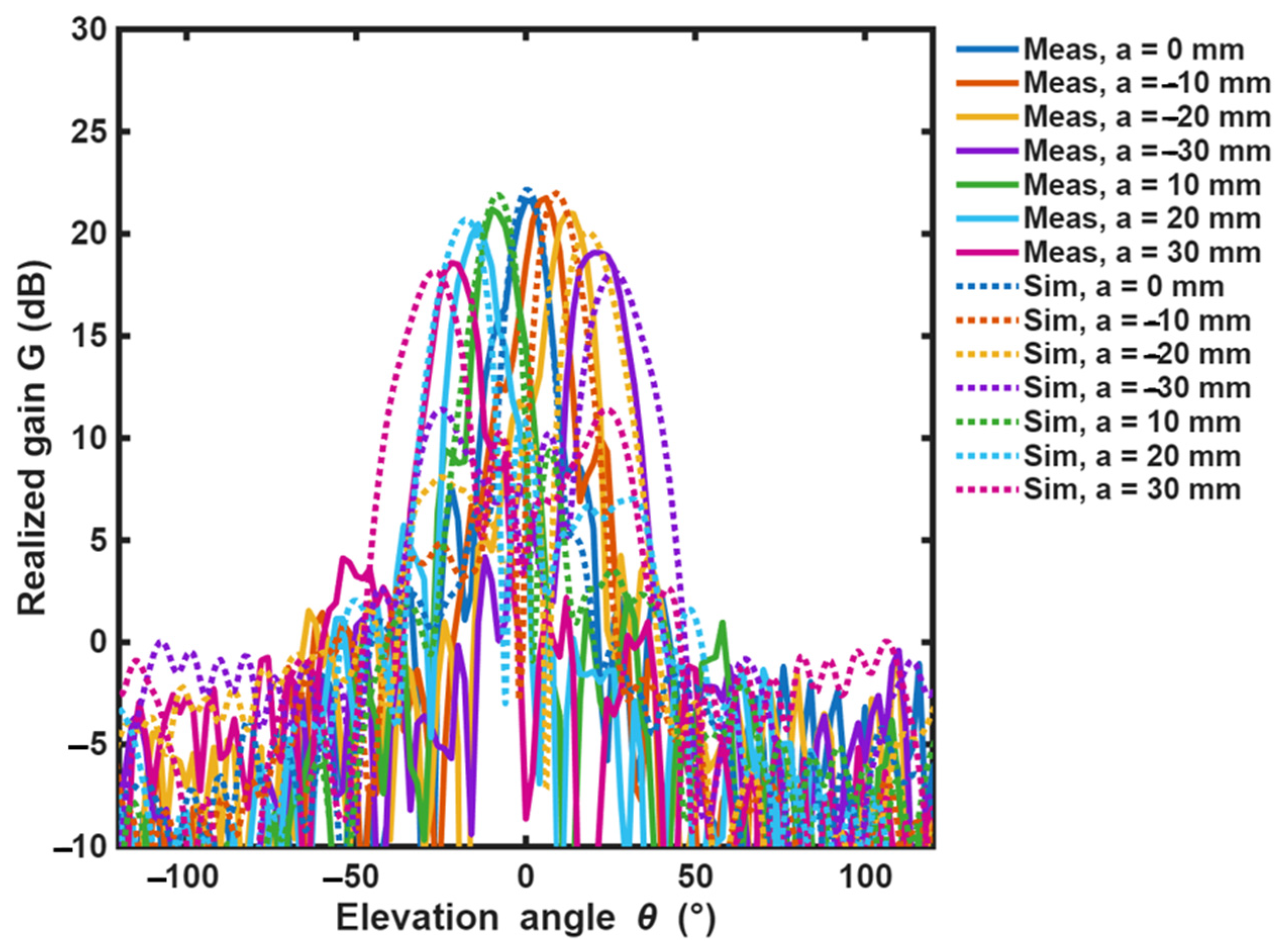
The position of the primary antenna has been shifted along the -direction and the y-direction, evaluating the effect in seven different positions per both directions, in the range with a step shift . Figure 17 shows the measured (solid curves) and simulated (dotted curves) realized gain for the different positions of the primary antenna along the -direction, for azimuth angle , at frequency . The plot of the measured realized gain obtained by shifting the primary feed along the -axis has not been included since it almost overlaps with the plot pertaining to the feed x-displacement, with a maximum difference in gain , which can reasonably be attributed to the TA construction and primary feed positioning tolerances.
Figure 17.
Measured (solid curves) and simulated (dotted curves) realized gain as a function of the elevation angle and at frequency for the transmitarray antenna system.
Good agreement between measurements and simulations can be observed. This confirms the reliability of the adopted electromagnetic model and demonstrates that the proposed phase compensation strategy is able to correctly predict the beam displacement induced by the feed shifting. In particular, simulations promise a slightly wider beamsteering range. The difference in maximum realized gain between measurements and simulations is . The maximum measured realized gain is obtained for and main beam direction . For the maximum shifting of , a main beam direction of has been obtained, with a scan loss . The obtained steering angle demonstrates the effectiveness of the proposed solution in achieving wide-angle beam control while preserving a relatively high gain level over the scanned range.
Table 2 lists the measured elevation angle , the main lobe measured realized gain , the measured side lobe level , and the measured scan loss for different positions The reported parameters provide a comprehensive evaluation of the transmitarray performance during beam scanning, including both the steering capability and the radiation pattern degradation associated with off-axis operation. Negligible differences in scan loss between the positions are due to the asymmetric geometry of the MCD-A unit cell. These results are in line with Equation (9).
Table 2.
Summary of the measured performance at 27 GHz.
Table 3 reports a comparison of the proposed TA with TAs from literature, in terms of maximum gain, scan loss, number of elements, central frequency, aperture efficiency, and total footprint as a fraction of the working wavelength. From the comparison, it is worth noting that the proposed transmitarray provides the highest aperture efficiency and wide scanning, with comparable scan loss if compared to those working at the same frequency [18,25], with a comparable footprint to [18].
Table 3.
Comparison with transmitarrays from the literature.
5. Conclusions
In this work, a novel transmitarray has been designed and fabricated. The complete 16 × 16 unit cell TA provides a measured gain , with a measured gain improvement with respect to the pristine primary antenna. It provides high aperture efficiency with a footprint comparable to the literature. Beamsteering in both the -direction and -direction with linear polarization, for a maximum angle and maximum scan loss , has been obtained. This TA could find application in new 5G FR2 band communications, requiring high gain, as an alternative to phased arrays. Further investigations may include low-profile feeding antennas controlled by a switching circuit for obtaining beamsteering without mechanical shifting.
Author Contributions
Conceptualization, A.M.L.; methodology, A.M.L. and F.A.; software, A.M.L.; validation, A.M.L., F.A. and F.M.; formal analysis, A.M.L.; investigation, A.M.L. and F.A.; resources, A.M.L.; data curation, A.M.L. and F.M.; writing—original draft preparation, A.M.L.; writing—review and editing, A.M.L., F.A., F.M., and F.P.; visualization, F.M.; supervision, F.P.; project administration, F.P.; funding acquisition, F.P. All authors have read and agreed to the published version of the manuscript.
Funding
This work has been partially developed within the research projects: ASI 2024-68-I.0 “Origami Reconfigurable Beam-steering Antennas with METAsurfaces for Communication on Small Satellites—ORBIT-META” under Grant CUP: F93C24000550001; in part by ASI 687/2022—MUR 341 15/03/22 “SPACE IT UP” under Grant CUP: D53C24000570006; and in part by HORIZON-TMA-MSCA-SE HORIZON TMA MSCA Staff Exchanges through “Cr4+:YAG/Polymer nanocomposite as alternative materials for Q-switched lasers: properties, modeling, and applications—ALTER-Q” under Grant 101182995.
Institutional Review Board Statement
Not applicable.
Informed Consent Statement
Not applicable.
Data Availability Statement
The original contributions presented in this study are included in the article. Further inquiries can be directed to the corresponding author.
Conflicts of Interest
The authors declare no conflicts of interest.
References
- Islam, M.M.; Islam, M.T.; Samsuzzaman, M.; Faruque, M.R.I. Compact metamaterial antenna for UWB applications. Electron. Lett. 2015, 51, 1222–1224. [Google Scholar] [CrossRef] [Scilit]
- Wu, G.-B.; Qu, S.-W.; Yang, S. Wide-Angle Beam-Scanning Reflectarray with Mechanical Steering. IEEE Trans. Antennas Propag. 2018, 66, 172–181. [Google Scholar] [CrossRef] [Scilit]
- Nayeri, P.; Yang, F.; Elsherbeni, A.Z. Bifocal Design and Aperture Phase Optimizations of Reflectarray Antennas for Wide-Angle Beam Scanning Performance. IEEE Trans. Antennas Propag. 2013, 61, 4588–4597. [Google Scholar] [CrossRef] [Scilit]
- Bian, C.; Zhou, D.; Zhang, Y.; Lv, D.; Deng, H.; Zhang, D. A Multipolarization Folded Transmitarray Antenna Based on Huygens’ Metasurface. IEEE Antennas Wirel. Propag. Lett. 2023, 22, 2783–2787. [Google Scholar] [CrossRef] [Scilit]
- Ryan, C.G.M.; Chaharmir, M.R.; Shaker, J.; Bray, J.R.; Antar, Y.M.; Ittipiboon, A. A wideband transmitarray using dual-resonant double square rings. IEEE Trans. Antennas Propag. 2010, 58, 1486–1493. [Google Scholar] [CrossRef] [Scilit]
- Liu, S.; Chen, Q. A Wideband, Multifunctional Reflect-Transmit-Array Antenna with Polarization-Dependent Operation. IEEE Trans. Antennas Propag. 2021, 69, 1383–1392. [Google Scholar] [CrossRef] [Scilit]
- Pham, T.K.; Guang, L.; González-Ovejero, D.; Sauleau, R. Dual-Band Transmitarray with Low Scan Loss for Satcom Applications. IEEE Trans. Antennas Propag. 2021, 69, 1775–1780. [Google Scholar] [CrossRef] [Scilit]
- Al-Joumayly, M.A.; Behdad, N. Wideband Planar Microwave Lenses Using Sub-Wavelength Spatial Phase Shifters. IEEE Trans. Antennas Propag. 2011, 59, 4542–4552. [Google Scholar] [CrossRef] [Scilit]
- Portosi, V.; Loconsole, A.M.; Campana, A.; Anelli, F.; Prudenzano, F. A Novel L-Shaped Metalens for Ultra-Wide Band (UWB) Antenna Gain Improvement. Appl. Sci. 2023, 13, 4802. [Google Scholar] [CrossRef] [Scilit]
- Ramazannia Tuloti, S.H.; Rezaei, P.; Tavakkol Hamedani, F. High-Efficient Wideband Transmitarray Antenna. IEEE Antennas Wirel. Propag. Lett. 2018, 17, 817–820. [Google Scholar] [CrossRef] [Scilit]
- Ren, X.; Zhou, Q.; Wang, K.X.; Ouyang, H.; Liu, R.; Xue, Q.; Wong, H. Wideband Circularly Polarized Transmitarray Antenna Based on Differential Unit Cell. IEEE Antennas Wirel. Propag. Lett. 2025, 24, 1689–1693. [Google Scholar] [CrossRef] [Scilit]
- Pham, K.T.; Sauleau, R.; Fourn, E.; Diaby, F.; Clemente, A.; Dussopt, L. Dual-Band Transmitarrays with Dual-Linear Polarization at Ka-Band. IEEE Trans. Antennas Propag. 2017, 65, 7009–7018. [Google Scholar] [CrossRef] [Scilit]
- Yang, H.; Yang, F.; Xu, S.; Mao, Y.; Li, M.; Cao, X. A 1-Bit 10×10 Reconfigurable Reflectarray Antenna: Design, Optimization, and Experiment. IEEE Trans. Antennas Propag. 2016, 64, 2246–2254. [Google Scholar] [CrossRef] [Scilit]
- Menzel, C.; Helgert, C.; Rockstuhl, C.; Kley, E.-B.; Tünnermann, A.; Pertsch, T.; Lederer, F. Asymmetric Transmission of Linearly Polarized Light at Optical Metamaterials. Phys. Rev. Lett. 2010, 104, 253902. [Google Scholar] [CrossRef] [Scilit] [PubMed]
- Lima, E.B.; Matos, S.A.; Costa, J.R.; Fernandes, C.A.; Fonseca, N.J.G. Circular Polarization Wide-angle Beam Steering at Ka-band by In-plane Translation of a Plate Lens Antenna. IEEE Trans. Antennas Propag. 2015, 63, 5443–5455. [Google Scholar] [CrossRef] [Scilit]
- Ge, Y.; Lin, C.; Liu, Y. Broadband Folded Transmitarray Antenna Based on an Ultrathin Transmission Polarizer. IEEE Trans. Antennas Propag. 2018, 66, 5974–5981. [Google Scholar] [CrossRef] [Scilit]
- Li, H.; Li, Y.B.; Gong, C.Y.; Dong, S.Y.; Wang, S.Y.; Wang, H.P.; Cui, T.J. Design of Programmable Transmitarray Antenna with Independent Controls of Transmission Amplitude and Phase. IEEE Trans. Antennas Propag. 2022, 70, 8086–8099. [Google Scholar] [CrossRef] [Scilit]
- Ganie, J.A.; Saurav, K. Two-Dimensional Switchable Beam Transmitarray Antenna for mm-Wave Base Stations and Vehicular Networks. IEEE Access 2023, 11, 34563–34574. [Google Scholar] [CrossRef] [Scilit]
- Liu, Y.; Zhang, H.; Deng, L. Design and Implementation of a Reconfigurable Transmitarray Employing Varactor-Tuned Huygens Elements for Dynamic Beam Shaping. IEEE Antennas Wirel. Propag. Lett. 2025, 24, 1542–1546. [Google Scholar] [CrossRef] [Scilit]
- de Kok, M.; Vertegaal, C.J.C.; Smolders, A.B.; Johannsen, U. A 34- to 36-GHz Active Transmitarray for Ka-Band Tracking Radar Using 5G Tx/Rx Beamforming ICs: Design and 64-Element Demonstrator. IEEE Trans. Antennas Propag. 2023, 71, 3260–3272. [Google Scholar] [CrossRef] [Scilit]
- Park, G.-W.; Lee, J.-H. High-Efficiency Metasurface Transmitarray Antenna Fed by Waveguide Cavity-Backed Slot Array. IEEE Antennas Wirel. Propag. Lett. 2025, 25, 458–462. [Google Scholar] [CrossRef] [Scilit]
- Shin, E.; Oh, J. Beam-Steerable Passive Transmitarray Optimized Based on an Adjacent Algorithm. IEEE Access 2021, 9, 28797–28804. [Google Scholar] [CrossRef] [Scilit]
- Hu, W.; Dong, M.; Luo, Q.; Cai, Y.; Wen, L.; Feng, T.-X.; Jiang, W.; Gao, S. Low-Cost Wide-Angle Beam-Scanning Transmitarray Antennas Using Lens-Loaded Patch Elements: A Proof-of-Concept Study. IEEE Antennas Wirel. Propag. Lett. 2022, 21, 2552–2556. [Google Scholar] [CrossRef] [Scilit]
- Li, T.-J.; Wang, G.-M.; Guo, W.-L.; Xin, K.-W.; Han, J.-Q.; Li, H.-P. Reconfigurable Folded Transmitarray Antenna with Low-Profile Based on Metasurfaces. IEEE Antennas Wirel. Propag. Lett. 2023, 22, 611–615. [Google Scholar] [CrossRef] [Scilit]
- Serup, D.E.; Pedersen, G.F.; Zhang, S. Combined Single-Layer K-Band Transmitarray and Beamforming S-Band Antenna Array for Satcom. IEEE Open J. Antennas Propag. 2022, 3, 1134–1140. [Google Scholar] [CrossRef] [Scilit]
- Liu, L.; Zhang, X.; Kenney, M.; Su, X.; Xu, N.; Ouyang, C.; Shi, Y.; Han, J.; Zhang, W.; Zhang, S. Broadband Metasurfaces with Simultaneous Control of Phase and Amplitude. Adv. Mater. 2014, 26, 5031–5036. [Google Scholar] [CrossRef] [Scilit] [PubMed]
- Cao, Y.; Zhang, M.; Fan, C.; Chen, J.-X. A Broadband Transmitarray Antenna Using a Metasurface-Based Element for Millimeter-Wave Applications. Micromachines 2024, 15, 383. [Google Scholar] [CrossRef] [Scilit] [PubMed]
- De Marco, R.; Arnieri, E.; Greco, F.; Bordbar, A.; Amendola, G.; Boccia, L. Low-Profile Dual-Band Dual-Polarized Transmitarray Antenna Based on Multilayer Frequency Selective Surfaces. IEEE Trans. Antennas Propag. 2023, 71, 7354–7362. [Google Scholar] [CrossRef] [Scilit]
- PourMohammadi, P.; Naseri, H.; Melouki, N.; Ahmed, F.; Zheng, Q.; Iqbal, A.; Denidni, T.A. A wideband beam steering transmitarray antenna for Ka-band applications. Int. J. Electron. Commun. (AEÜ) 2025, 193, 155720. [Google Scholar] [CrossRef] [Scilit]
- Vaquero, A.F.; Teixeira, J.; Matos, S.A.; Arrebola, M.; Costa, J.R.; Felicio, J.M.; Fernandes, C.A.; Fonseca, N.J.G. Design of Low-Profile Transmitarray Antennas with Wide Mechanical Beam Steering at Millimeter Waves. IEEE Trans. Antennas Propag. 2023, 71, 3713–3718. [Google Scholar] [CrossRef] [Scilit]

Disclaimer/Publisher’s Note: The statements, opinions and data contained in all publications are solely those of the individual author(s) and contributor(s) and not of MDPI and/or the editor(s). MDPI and/or the editor(s) disclaim responsibility for any injury to people or property resulting from any ideas, methods, instructions or products referred to in the content. |
© 2026 by the authors. Licensee MDPI, Basel, Switzerland. This article is an open access article distributed under the terms and conditions of the Creative Commons Attribution (CC BY) license.