


Abstract
Slotless permanent magnet synchronous motors (PMSMs) have recently attracted significant attention for robotic and high-speed machine applications because they eliminate cogging torque and reduce iron loss through the absence of stator teeth. However, removing the stator teeth increases the effective airgap, resulting in extremely low synchronous inductance and introducing electrical challenges such as reduced control stability and increased current harmonics during pulse-width modulation (PWM) operation in inverter drive systems. In this paper, the current harmonic characteristics of a slotless PMSM are investigated with respect to switching frequency. Based on the mathematical model, the effects of switching frequency on a slotless PMSM drive system employing a MOSFET inverter are analyzed. In addition, an experimental setup, including a 700 W slotless PMSM and a MOSFET inverter, is implemented to evaluate the current harmonic characteristics under different switching frequencies of 25 kHz, 50 kHz, and 99 kHz. The total harmonic distortion of current at 99 kHz is reduced by approximately 6.73%p and 3.57%p compared with operation at 25 kHz and 50 kHz, respectively. The experimental results demonstrate the influence of PWM operation on the current characteristics of the slotless PMSM and verify the importance of high switching frequency operation for improving current performance.
1. Introduction
Recently, global industries have been undergoing an unprecedented transition to respond to climate change [1,2,3]. Since the 2015 Paris Agreement, the transition toward electrification in the transportation sector has accelerated [4,5]. Due to this trend, the electric vehicle (EV) market is growing exponentially. In addition, the electrical powertrain has become a decisive factor in the overall system’s competitiveness [6]. Due to this trend, electric machines with high torque density, high-power density, and high efficiency are necessary for this application. Although various electric machine topologies have been developed for a wide range of applications, including electric vehicles, drones, aircraft, robotics, and industrial automation, the permanent magnet synchronous motor (PMSM) with rare-earth permanent magnets has become the industrial standard because of its high-power density and superior electromagnetic performance [7,8,9,10,11,12]. Consequently, compared with other machine topologies, such as the induction motor, synchronous reluctance motor, wound field synchronous motor, and switched reluctance motor, PMSMs have been widely adopted in applications requiring compact size, high efficiency, and high dynamic performance [13,14,15,16,17].
Although conventional PMSMs have outstanding advantages, they inherently suffer from mechanical and magnetic limitations, such as cogging torque and torque ripple caused by the slotted stator structure [18,19]. As emerging high-end applications demand ultra-smooth rotation, high precision, and higher operational speeds, overcoming these physical bottlenecks has become a critical engineering challenge [20,21]. To address these limitations, the slotless PMSM topology has emerged as a highly promising alternative [20,22]. Since the stator core teeth in the slotless PMSM are eliminated, the windings are attached to the stator yoke directly or fixed in the airgap with nonmagnetic material. The structural properties provide a uniform magnetic airgap, resulting in the elimination of the cogging torque generated by the interaction between the stator teeth and the permanent magnets of the motor [23]. Additionally, the iron loss and harmonic loss are extremely low because the slotless PMSM does not have variation in the magnetic flux density generated by the stator teeth at high rotating speed [24].
Voltage source inverters are widely employed in motor drive applications. During a switching event, the voltage applied to the motor changes abruptly, generating current ripple. The magnitude of the current ripple is proportional to the DC-link voltage and inversely proportional to both the motor inductance and the switching period. Owing to the absence of stator teeth, slotless machines exhibit a larger effective magnetic airgap than conventional slotted machines, resulting in significantly lower inductance. Although low inductance decreases the time constant and enables a fast current response [25], it also increases current ripple during pulse-width modulation (PWM) operation in a voltage source inverter because the current ripple is inversely proportional to the inductance and switching frequency. Excessive current ripple can lead to current tracking errors, increased losses, and reduced drive-system efficiency [26,27,28].
Several studies have investigated these control challenges and the suppression of the current ripple [29,30,31,32,33,34]. In ref. [29] and [30], LC filters are proposed to reduce the current ripple in motor drive systems. In addition, an embedded inductor is introduced to suppress the current ripple while extending the operating speed range [31]. However, these approaches increase system volume and require additional passive components, resulting in higher cost and lower power density. In ref. [32,33,34], multi-level inverter topologies have been proposed to reduce the current ripple by generating multiple voltage levels. Although multi-level inverters can effectively mitigate current ripple, they require a larger number of switching devices and more complex control schemes, increasing both system cost and implementation complexity.
Another approach to reducing current ripple is to increase the switching frequency to approximately 50–100 kHz [27]. However, conventional silicon (Si)-based insulated-gate bipolar transistors (IGBTs) are typically limited to switching frequencies of approximately 2–10 kHz because of thermal constraints [35,36,37]. As a result, additional passive components, such as external inductors, are often required to suppress current ripple, which limits control bandwidth and system power density. Recently, wide band gap (WBG) materials such as silicon carbide (SiC) and gallium nitride (GaN) have been studied for motor drives, which are suitable for the high-speed PMSM drives due to their superior electric field strength and thermal conductivity compared to the IGBTs [36,37,38,39]. These characteristics enable high-frequency switching operation, making WBG-based inverters particularly suitable for slotless PMSM drives with low inductance. Although slotless machine drive systems have been investigated in previous studies, most existing research has focused primarily on power-electronic aspects. The fundamental mechanism of current-ripple generation and the relationship between switching frequency and current harmonic characteristics in slotless PMSMs have not been sufficiently investigated.
In this paper, the switching frequency effect is investigated in terms of the current ripple and controllability through a mathematical model and experiments under space vector PWM (SVPWM). Through the analytical approach, the relationship between the motor inductance and switching frequency is investigated in terms of the current ripple, controllability, and switching loss. To achieve a high switching frequency, the motor drive system with a slotless PMSM and a MOSFET inverter is implemented to investigate the current harmonics according to the switching frequency. In addition, the current harmonic characteristics of a slotless PMSM with a MOSFET inverter are experimentally investigated, demonstrating that a high switching frequency is required to reduce current harmonic and be controllability in a slotless PMSM with a MOSFET inverter.
This paper is organized as follows. The mathematical model of the slotless PMSM is addressed in Section 2. In Section 3, the switching frequency effect in the slotless PMWM with a MOSFET inverter is investigated. In Section 4, the experiment setup of the slotless PMSM with a MOSFET inverter and the current harmonics in this system are experimentally investigated. Section 5 presents the conclusions.
2. Mathematical Model of Slotless PMSM
A permanent magnet synchronous motor (PMSM) converts electromagnetic energy with the interaction between the current flowing through each phase winding and the magnetic flux of the permanent magnet attached to the rotor. In the 3-phase coordinate system, the voltage equations of each phase are defined as the sum of the voltage drop of winding resistance, the induced electromotive force (EMF) proportional to the rate of change of current and the back EMF %p by the rotor. The voltage equations of each phase can be expressed as follows:
where va, vb, vc are phase voltage, ia, ib, ic are phase current, Rs is stator resistance, Laa, Lbb, Lcc are self-inductance, Mab, Mbc, Mca, are mutual inductance, and λam, λbm, λcm are phase flux linkage by permanent magnet. The entire flux linkage of each phase can be expressed as Equation (2).
where θe is the electrical angle, and λpm is the magnitude of flux linkage by permanent magnet. To eliminate time varying components, Park Transform is applied to convert the stator reference frame into a dq-axis frame. The transformed voltage equations can be expressed as follows:
where vd and vq are d- and q-axis voltage, respectively, id and iq are d- and q-axis current, respectively, and Ld and Lq are d- and q-axis inductance, respectively. Since the surface PMSM has a uniform magnetic airgap, the d-axis inductance is identical to the q-axis inductance (Ld = Lq), leading to zero reluctance torque. The total torque in a surface PMSM can be expressed linearly with the multiple of the q-axis current and the flux linkage of the permanent magnet as expressed in Equation (4).
where Te is the torque, p is the number of pole-pair, and Kt is the torque constant.
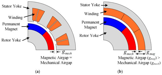
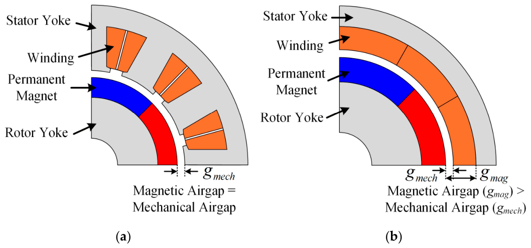
As shown in Equation (4), the torque is directly determined by the q-axis current, indicating that the torque ripple depends on the current ripple. Although the sinusoidal current control is conducted, the current variation still occurs because the applied voltage from the inverter changes according to the switching status of the inverter. This voltage variation generates the current ripple at the switching frequency in PMSM drive system, thereby increasing the torque ripple, as expressed in Equation (4). In addition, the current ripple is affected by the motor parameters, as expressed in Equation (3), which indicates that the current ripple is inversely proportional to the motor inductance. Figure 1 illustrates the configurations of slotted and slotless PMSMs. As shown in Figure 1, the mechanical airgap is identical to the magnetic airgap in a slotted PMSM, whereas the magnetic airgap is larger than the mechanical airgap in a slotless PMSM. Since the motor inductance is inversely proportional to the magnetic airgap, the inductance of a slotless PMSM is lower than that of a slotted PMSM. Consequently, the slotless PMSM exhibits higher current ripple compared to the slotted PMSM. These results demonstrate that current harmonic analysis of a slotless PMSMs under PWM operation is essential because the low inductance leads to significant current harmonics. In the next Subsection, the challenges of motor drive with low inductance are addressed.
Figure 1.
Configuration of slotted PMSM and slotless PMSM: (a) slotted PMSM; (b) slotless PMSM.
3. Challenges of Motor Drive with Slotless PMSM During PWM
3.1. Stability of Control System
Although low inductance can improve the dynamic response of a PMSM, it also introduces control challenges because it requires a high control bandwidth, resulting in stringent requirements for analog-to-digital converter (ADC) sampling speed and PWM switching frequency [40]. The transfer function of the open loop system can be expressed as the product of the controller, the plant, and digital control delay as follows:
where G(s), C(s), and P(s) are the transfer functions of the open loop system, the controller, and the plant, respectively, Td is the digital control delay, and ωcc is the current control bandwidth. The current control bandwidth can be selected based on control theory as follows:
where Kp is the control gain of the proportional controller of current control, and Ls is the phase inductance. Since the slotless machine has low inductance, the current control bandwidth should be enlarged.
Phase margin means how much phase angle is far from 180° when open loop gain is 0 dB. Phase angle of G(s) and phase margin are as follows:
where ∠G(s) is the phase of transfer function and PM is the phase margin.
Since the slotless PMSM has a low inductance compared to slotted PMSM, the current control bandwidth is significantly higher, resulting in sensitivity to the delay. To target a high bandwidth in current control loop, this delay causes a sharp reduction in the phase margin, triggering overshoot or oscillations.
3.2. Current Ripple in PMSM Drive System
Reconfiguring the system into state-space equations to analyze the dynamic characteristics from a control perspective clarifies the impact of inductance. The dq-axes current change rates are as follows:
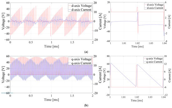
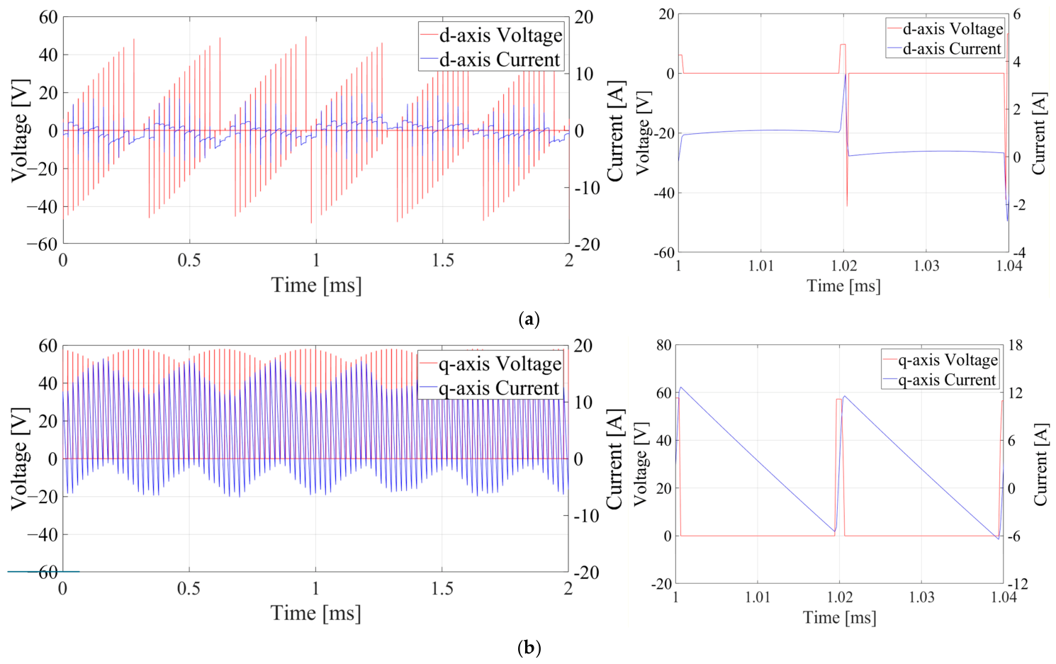
As shown in Equation (8), the current ripple depends on the input voltage and inductance. Since conventional inverters are voltage source-based inverters, the dq-axis voltage should be rapidly changed according to the switching frequency during PMW operation, as illustrated in Figure 2. Since the time variation of dq-axis current is inversely proportional to the inductance, as expressed in Equation (8), the high current ripple in the PWM period is caused and drops down the current following performance of the controller system, as illustrated in Figure 2. That demonstrates that the current ripple dominantly depends on the switching frequency, DC-link voltage, and inductance. Furthermore, because the phase current is measured and controlled by the digital signal processor (DSP) during PWM operation, a low switching frequency increases current distortion and reduces the current-control bandwidth, which may ultimately lead to current-control failure. This characteristic becomes a primary factor that impedes the stability of the system by amplifying the phase delay of the control loop and the sensitivity of the system to analog-to-digital converter (ADC) sampling and computation delays. Therefore, a high bandwidth inverter system and a fast switching frequency strategy are necessary to suppress the electrical sensitivity. Moreover, thermal overload and efficiency degradation can occur because higher current ripple increases the root-mean-square (RMS) current value, resulting in increased stator copper loss and heat generation according to the power equation, thereby reducing the overall system efficiency.
Figure 2.
dq-axis voltage and current under PWM control under switching frequency of 25 kHz: (a) d-axis voltage and current (left: one-period view, right: zoomed-in view); (b) q-axis voltage and current (left: one-period view, right: zoomed-in view).
The low-inductance characteristic of slotless PMSMs causes steep current variations even under small voltage changes. As a result, conventional control systems operating at a switching frequency of 10 kHz cannot maintain a sufficiently stable bandwidth and inherently suffer from high current ripple. This excessive current ripple increases copper loss in the windings and becomes a major factor that reduces energy conversion efficiency. Furthermore, the reduced time constant of the control loop increases the sensitivity to sampling delays, while the reduced phase margin can cause oscillations or even instability in the control response. Therefore, overcoming the electrical and control limitations while preserving the inherent mechanical advantages of slotless motors requires a novel design approach that utilizes the high-speed switching capability of SiC MOSFETs to achieve high control precision.
3.3. Current Ripple Analysis Under SVPWMss
SVPWM generates target voltage by synthesizing discrete active vector and zero vector. In this process, the difference between the inverter output voltage and the idle required voltage from the controller is applied to the winding and makes harmonic current ripple. The error of the voltage vector appears as follows.
where is the difference between pwm voltage and voltage reference, vpwm is the PWM voltage, and is the reference voltage. Assume that the voltage drop in the stator winding is small enough to ignore compared with the voltage drop in the inductance in the motor equivalent circuit, so the voltage drop is fully applied across the synchronous inductance. It becomes the core factor that generates harmonic ripple current, not contributing to the generation of output torque. In an arbitrary switching period, sudden change of current ripple can be expressed as the integral of the voltage error.
where iripple is the current ripple. Assume that the command voltage vector is located in the first sector of the hexagonal space vector to reveal the peak-to-peak value of the ripple current, in a single switching period of SVPWM. In the synchronous 7-segment switching pattern, the voltage application time of each voltage vectors is selected by the modulation index and angle. The modulation index is the ratio between DC link voltage and command voltage. While the zero-voltage vector is applied (V0 or V7), the output voltage of the inverter is zero. At that moment, the error voltage applied to the motor is , and the current rises steeply. The maximum ripple amplitude can be derived mathematically as shown in Equation (11).
where Vdc is the DC-link voltage, and fsw is the switching frequency. Equation (10) shows that current ripple is proportional to the DC link voltage and inversely proportional to synchronous inductance and switching frequency. In the motor drive system, reducing the DC link voltage is impossible because it is directly linked to the output power. Although applying an external inductor to increase the total inductance of the system could be an easy way to solve the problem, it expands the total volume and weight of the system. Consequently, increasing the switching frequency is the solution to reduce the current ripple of the slotless PMSM driving system.
The voltage error generated in the SVPWM process generates harmonic components in the frequency domain, not only the pulse in the time domain. The harmonic frequency generated by the nonlinear switching of inverter consists of the fundamental frequency and the switching frequency. In general, the major voltage harmonic components generated by a 2-level inverter appear as sidebands around integer multiples of the switching frequency, in accordance with Equation (11).
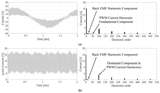
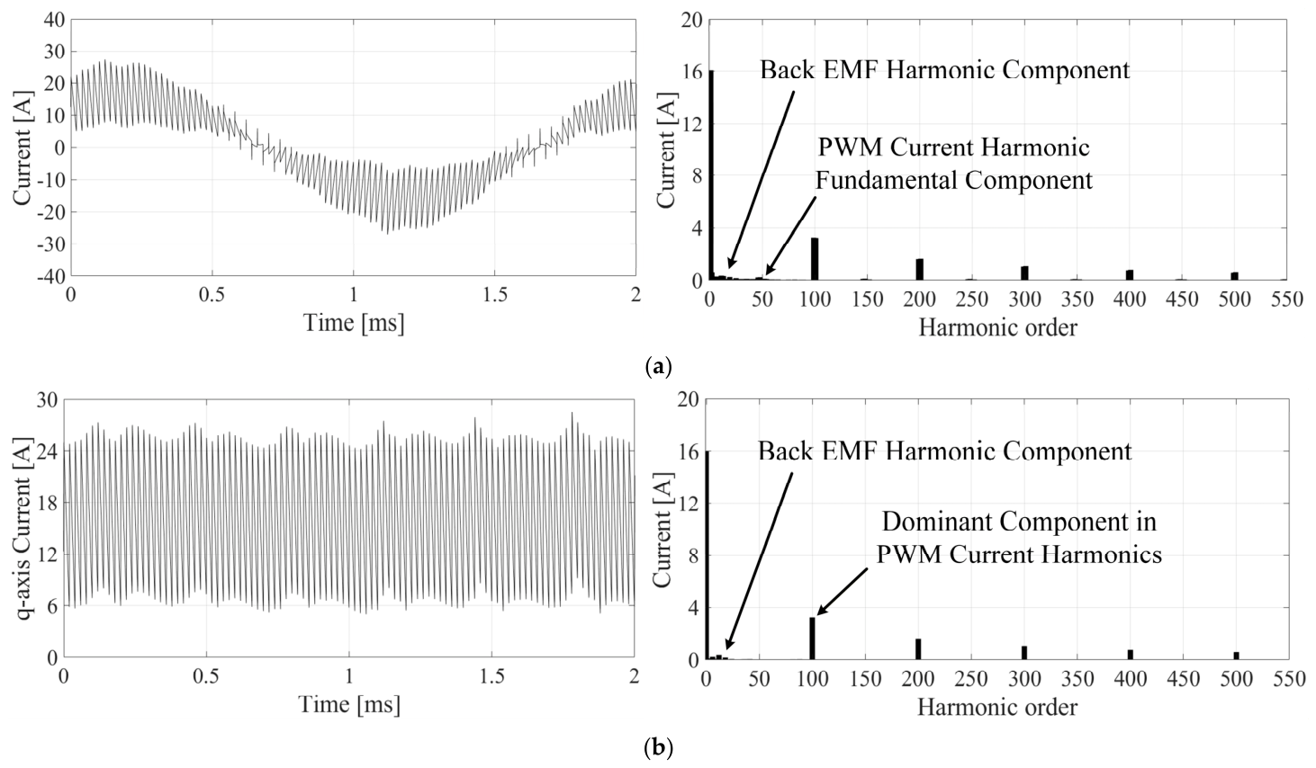
where fh is the harmonic frequency, and fe is the fundamental frequency. Figure 3 shows the current waveform of Phase A under a switching frequency of 25 kHz. Since the fundamental frequency is 500 Hz, the harmonic order of the switching frequency is 50, as illustrated in Figure 3a. Although the harmonic order of the switching frequency is 50, the dominant harmonic order is 100 because symmetric space vector PWM is employed. In the synchronous frame, the q-axis current harmonic depends on the switching frequency, as illustrated in Figure 3b. This harmonic distribution is directly connected to control precision. If at the switching frequency, the central axis of harmonic energy shifts from low bandwidth to high bandwidth, this phenomenon is called spectral shift. It contributes to reducing harmonic components when combined with a low pass filter of the system.
Figure 3.
Current waveform and frequency analysis: (a) Phase A current; (b) q-axis current.
Winding impedance of a slotless PMSM increases linearly with the switching frequency because it is an inductive load. Therefore, if the same harmonic voltage error is loaded, at the higher frequency range, the RMS value of the actual harmonic current decreases inversely, as described in Equation (12).
where Ih is the current harmonic component, Vh is the voltage harmonic component, and Zh is the impedance of high frequency. Equation (12) shows that increasing switching frequency is the way to reduce harmonic current when synchronous inductance is fixed. Because total harmonic distortion (THD) is proportional to the sum of square of each harmonic current, increasing switching frequency leads to an exponential improvement in THD.
where THDi is the current THD. The low inductance system including slotless PMSM does not have filtering capability. It needs to shift harmonic energy to high frequency range.
3.4. Motor Drive Loss and Inductor Design Perspective
Si-based IGBT has stable performance and is advantageous in terms of cost. Due to the tail current of the bipolar transistor, the IGBT has physical limits that allow it to use switching frequency only around 2–10 kHz. However, as a unipolar transistor, MOSFET has fast switching frequency because it does not have minority carrier recombination process, and it allows higher switching frequency more than 20 kHz. The efficiency characteristics of MOSFET-based inverter can be defined in conduction loss and switching loss. While IGBT has a knee voltage characteristic—it needs a small amount of voltage to conduct current—MOSFET has a linear resistance characteristic. The conduction loss can be expressed as Equation (15).
where Pcond is the conduction loss, Irms is the current rms value in switching devices, and RDS(on) is the on-resistance of the switching devices. This resistive characteristic contributes to increased energy conversion efficiency with a small voltage drop in the light load region. Switching loss (Psw) is proportional to the energy loss (Eon, Eoff) during turn on/off and switching frequency, as shown in Equation (16).
where Psw is the switching loss, and Eon and Eoff are the energy loss during turn on and turn off, respectively. As a result, MOSFET inverter maximizes voltage utilization rate and minimizes dead time effect with high switching frequency characteristics. In addition, it provides high resolution voltage control circumstance required for controlling slotless PMSM.
Copper loss of a motor is proportional to the stator winding resistance and RMS of current. In the situation, the RMS of current is defined as the sum of fundamental current and harmonic ripple, as shown in Equation (17).
As derived in Equation (13), the peak-to-peak value of current ripple decreases proportionally to the switching frequency, meaning a decrease in harmonic components. Therefore, high frequency driving can reduce copper loss, generating no torque but heat, and it is linked directly to the efficiency of the driving system.
Applying an external inductor to the system to suppress current ripple compromises the power density of the total system. According to the area product theory, for determining the inductor volume, the volume of inductor is proportional to the inductance and current.
where Ap is the copper area of external inductor, Lext is the inductance of external inductor, Ipeak is the peak value of current, Bmax is the maximum magnetic flux density in inductor, J is the current density, Kw is the winding fill factor, and VL is the volume of the external inductor. According to Equations (18), the additional volume of connecting a few mH unit external inductor to the system is larger than the volume of the motor. This results in a hardware-level negation of high-power density, which is the intrinsic value of the slotless topology adopted for miniaturization and weight reduction. However, SiC-based high frequency drive does not have a volume increase, and it can control current more stably without passive components. Therefore, high frequency control is a proper way to satisfy system specification while preserving mechanical advantages of a slotless motor.
4. Experimental Results
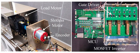
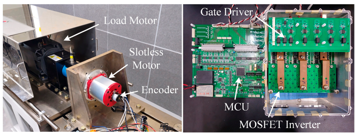
To verify the current characteristics of the slotless PMSM driven by a MOSFET inverter, under different switching frequencies, an experimental setup, consisting of a load motor, a slotless motor with 20 poles, DSP with TMS320F28379D from Texas Instruments, Dallas, TX, USA, and an inverter with N-channel silicon MOSFET (IPB180N10S4-01 from Infineon) was implemented, as illustrated in Figure 4. The specification of slotless PMSM drive system is summarized in Table 1. Control code debugging was performed using Code Composer Studio (CCS) and the EasyDSP interface of the inverter hardware. The inverter output voltage/current and digital-to-analog converter (DAC) signals were monitored using an oscilloscope (HDO8000 from Teledyne Technologies, Thousand Oaks, CA, USA). In addition, carrier-based SVPWM was employed to modulate the inverter output voltage, and a proportional–integral (PI) controller was used for current control, as shown in Table 1. The speed was controlled by the dynamometer, whereas the torque was controlled by slotess PMSM using id = 0 current control, which is widely employed for maximum torque per ampere control of slotless PMSM. In the experiments, the q-axis current command was set to 3, 6, 9, 12, and 16 Apeak corresponding to the rated current of 16 Apeak for slotless PMSM. In addition, the phase current of the slotless PMSM was measured at inverter switching frequencies of 25, 50, and 99 kHz to experimentally investigate the effect of switching frequency on the current harmonic characteristics. The phase currents of phases A, B, and C and the DC-link voltage were measured using oscilloscope probes, while the electrical angle was obtained through the DAC channel. In addition, the output torque, line-to-line voltage, output power, and THD were measured using the dynamometer system and a power analyzer.
Figure 4.
Experimental environment.
Table 1.
Specification of slotless PMSM drive system.
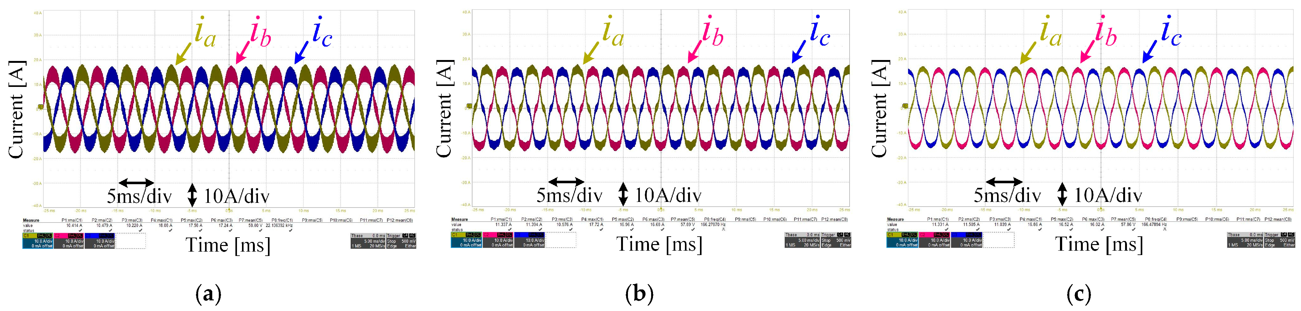
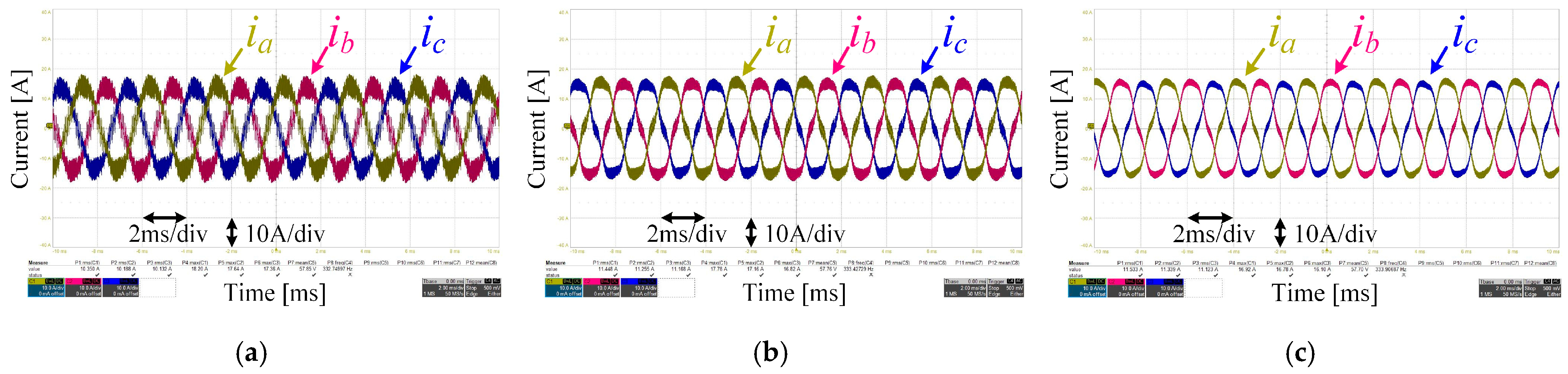
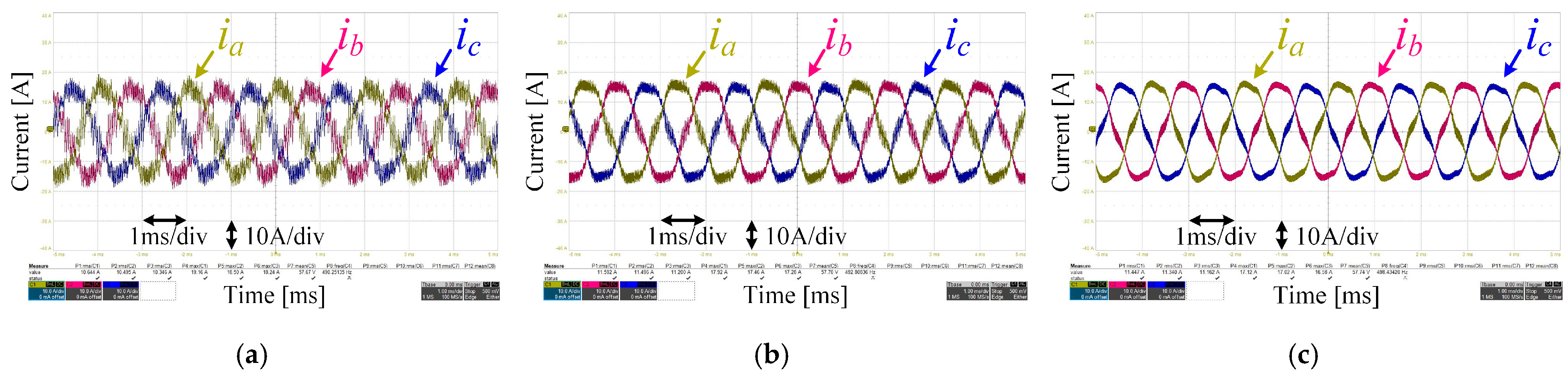
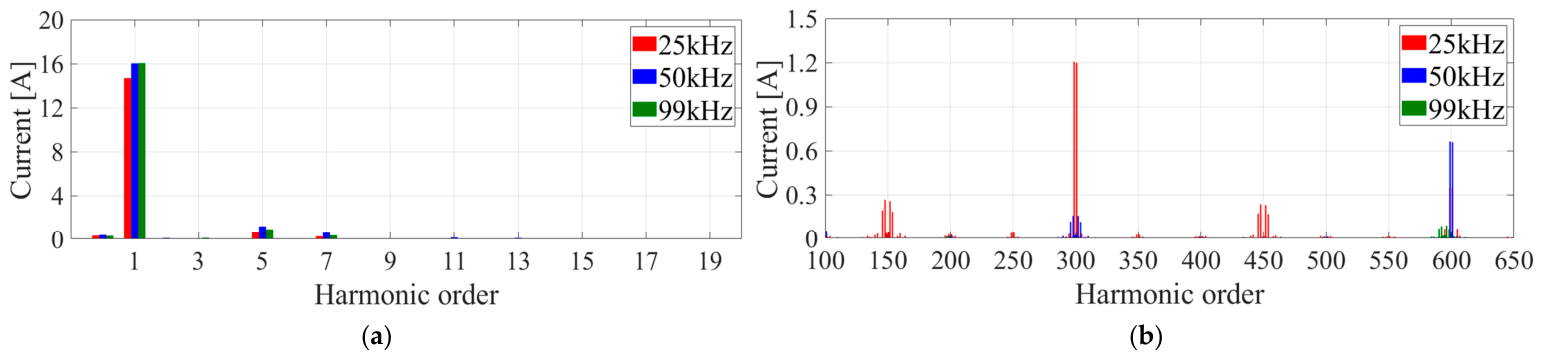
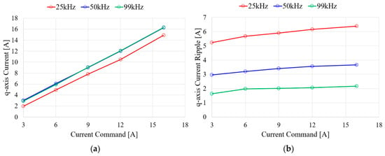
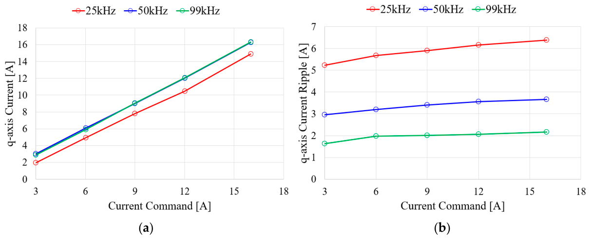
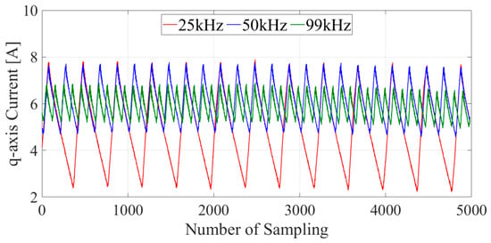
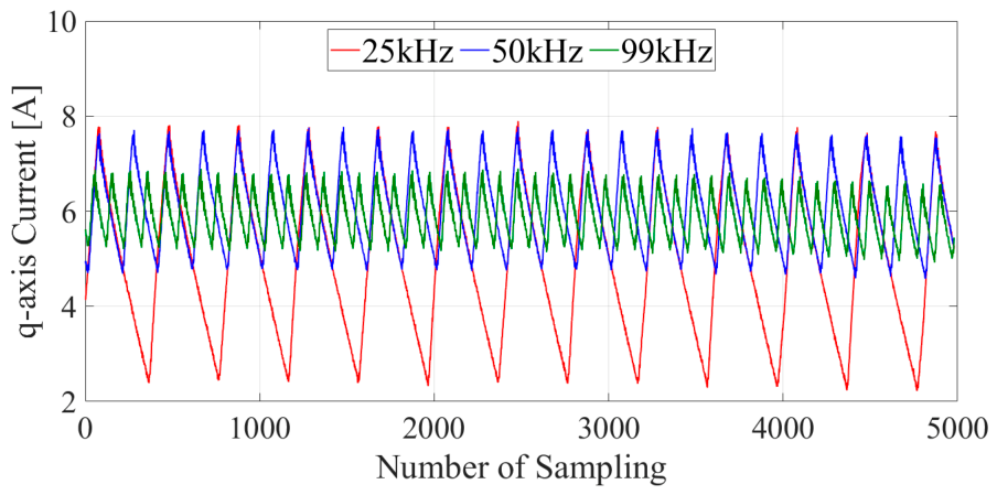
Figure 5, Figure 6 and Figure 7 show the measured current waveforms under 1000 rpm, 2000 rpm, and 3000 rpm, respectively. During PWM operation, current variation occurs, and the current ripple decreases as the switching frequency increases, as discussed in Section 3.3. As shown in Figure 7, the current distortion under 25 kHz is higher compared with other operating conditions because the sampling is not enough to control the current under low switching frequency. The current ripple characteristics under the different switching frequencies are compared at the speed of 1000 rpm, where the current distortion is lower at the switching frequency of 25 kHz, as illustrated in Figure 8, Figure 9 and Figure 10. Figure 8 presents the FFT results of the measured currents at the speed of 1000 rpm. The current harmonic components depend on both the back EMF harmonics and the switching frequency, as illustrated in Figure 8. Under the low-switching-frequency condition of 25 kHz, the current harmonic components become significant, causing the fundamental current component to fail to accurately track the commanded current, as discussed in Section 3.1. In addition, the dominant current harmonic components are strongly related to twice the switching frequency, as shown in Figure 8b. As the switching frequency increases, the current harmonic components are significantly reduced. Table 2 summarizes the current characteristics, including the RMS phase current, fundamental current component, and THD of the phase current. As shown in Table 2, the THD of the phase current at 99 kHz is reduced by approximately 6.73%p and 3.57%p compared with those at 25 kHz and 50 kHz, respectively. Figure 9 shows the q-axis current and current ripple according to the switching frequency at the speed of 1000 rpm. Under low-switching-frequency conditions, the q-axis current fails to accurately follow the commanded current. In contrast, the q-axis current ripple decreases as the switching frequency increases. Figure 10 presents the calculated q-axis current obtained from the measured three-phase currents and rotor position under a q-axis current command of 6 A at the speed of 1000 rpm. As the switching frequency increases, the ripple frequency increases, while the magnitude of the current ripple decreases, as illustrated in Figure 8.
Figure 5.
Output current waveform (iq = 16 Apeak at 1000 rpm): (a) 25 kHz; (b) 50 kHz; (c) 99 kHz.
Figure 6.
Output current waveform (iq = 16 Apeak at 2000 rpm): (a) 25 kHz; (b) 50 kHz; (c) 99 kHz.
Figure 7.
Output current waveform (iq = 16 Apeak at 3000 rpm): (a) 25 kHz; (b) 50 kHz; (c) 99 kHz.
Figure 8.
FFT results of measured current (iq = 16 Apeak at 1000 rpm): (a) low harmonic order; (b) high harmonic order.
Figure 9.
q-axis current comparison at 1000 rpm; (a) average current; (b) q-axis current ripple.
Figure 10.
Current ripple comparison for switching frequency under current command of 6 A at 1000 rpm.
Table 2.
Current characteristics according to switching frequency at 1000 rpm.
5. Conclusions
In this paper, the control challenges arising from the low-inductance characteristics of slotless PMSMs are systematically analyzed. During PWM operation in a voltage source inverter, the voltage applied to the motor continuously changes, resulting in a current ripple which is inversely proportional to the phase inductance. Since slotless PMSMs inherently exhibit low inductance, they experience higher current ripple compared to conventional electric machines. The challenges of slotless PMSM drive systems with a voltage source inverter are discussed in terms of control system stability, current ripple characteristics, and the influence of the drive system. Through the analysis of current ripple, it is demonstrated that PMSMs with low inductance require high switching frequencies to effectively suppress current ripple. The inverter with MOSFET and 700 W slotless PMSM is implemented to experimentally investigate the current ripple at switching frequencies of the inverter, including 25 kHz, 50 kHz, and 99 kHz. The current control fails under low switching frequency of 25 kHz, and the experimental results demonstrate that the current ripple at 99 kHz switching frequency achieve the reduction of 6.73%p and 3.57%p compared with those at 25 kHz and 50 kHz switching frequency, respectively. This study highlights the challenges associated with driving low-inductance slotless machines and demonstrates the potential of next-generation WBG-based motor drive systems for such applications.
For applications requiring ultra-precision and high-response drives, such as humanoid robots, slotless motors offer significant structural advantages, including zero cogging torque, high responsiveness, and lightweight design. However, their practical application has been limited by challenges such as extremely low inductance, severe current ripple, and thermal instability. Therefore, the high-performance motor drive system with high switching frequency enabled by WBG devices can effectively address these limitations while preventing the inherent advantages of slotless machine structure. In addition, the system-level optimization considering system efficiency should be further investigated to clarify the capabilities, limitation, and power level of motor drive system.
Although this study investigated the effect of switching frequency on the current harmonic characteristics of a slotless PMSM drive system, a comprehensive comparison of different modulation methods, including sinusoidal PWM, discontinuous PWM, pulse amplitude modulation, and pulse frequency modulation, remains a subject for future research. Future work will focus on evaluating these modulation strategies in terms of current harmonics, inverter losses, motor losses, and overall system efficiency.
Author Contributions
Conceptualization, I.-G.L.; methodology, I.-G.L.; software, I.-G.L.; validation, I.-G.L. and H.K.; formal analysis, I.-G.L.; investigation, I.-G.L.; resources, I.-G.L.; data curation, I.-G.L.; writing—original draft preparation, I.-G.L.; writing—review and editing, H.K.; visualization, H.K.; supervision, H.K.; project administration, H.K.; funding acquisition, H.K. All authors have read and agreed to the published version of the manuscript.
Funding
This research received no external funding.
Institutional Review Board Statement
Not applicable.
Informed Consent Statement
Not applicable.
Data Availability Statement
The original contributions presented in this study are included in the article. Further inquiries can be directed to the corresponding author.
Conflicts of Interest
The authors declare no conflicts of interest.
References
- Sanguesa, J.A.; Torres-Sanz, V.; Garrido, P.; Martinez, F.J.; Marquez-Barja, J.M. A Review on Electric Vehicles: Technologies and Challenges. Smart Cities 2021, 4, 372–404. [Google Scholar] [CrossRef] [Scilit]
- Un-Noor, F.; Padmanaban, S.; Mihet-Popa, L.; Mollah, M.N.; Hossain, E. A Comprehensive Study of Key Electric Vehicle (EV) Components, Technologies, Challenges, Impacts, and Future Direction of Development. Energies 2017, 10, 1217. [Google Scholar] [CrossRef] [Scilit]
- Liu, C.; Chau, K.T.; Lee, C.H.T.; Song, Z. A Critical Review of Advanced Electric Machines and Control Strategies for Electric Vehicles. Proc. IEEE 2021, 109, 1004–1028. [Google Scholar]
- Khalid, M.R.; Khan, I.A.; Hameed, S.; Asghar, M.S.J.; Ro, J.-S. A Comprehensive Review on Structural Topologies, Power Levels, Energy Storage Systems, and Standards for Electric Vehicle Charging Stations and Their Impacts on Grid. IEEE Access 2021, 9, 128069–128094. [Google Scholar] [CrossRef] [Scilit]
- Kong, P.-Y.; Karagiannidis, G.K. Charging Schemes for Plug-In Hybrid Electric Vehicles in Smart Grid: A Survey. IEEE Access 2016, 4, 6846–6875. [Google Scholar] [CrossRef] [Scilit]
- Krithika, V.; Subramani, C. A Comprehensive Review on Choice of Hybrid Vehicles and Power Converters, Control Strategies for Hybrid Electric Vehicles. Int. J. Energy Res. 2018, 42, 1789–1812. [Google Scholar]
- Zheng, P.; Liu, W.; Gao, Y.; Tong, C.; Sui, Y. Review of Fault Diagnosis and Fault-Tolerant Control Technologies for Permanent-Magnet Synchronous Machine. CES Trans. Electr. Mach. Syst. 2025, 9, 320–339. [Google Scholar] [CrossRef] [Scilit]
- Ocak, O.; Aydin, M. An Innovative Semi-FEA Based, Variable Magnet-Step-Skew to Minimize Cogging Torque and Torque Pulsations in Permanent Magnet Synchronous Motors. IEEE Access 2020, 8, 210775–210783. [Google Scholar] [CrossRef] [Scilit]
- Zhao, J.; Wang, Z.; Liu, H.; Ning, F.; Hong, X.; Du, J.; Yu, M. Modal Analysis and Structure Optimization of Permanent Magnet Synchronous Motor. IEEE Access 2020, 8, 151856–151865. [Google Scholar] [CrossRef] [Scilit]
- Chen, B.; Xiao, Y.; Shi, J.; Hu, Y.; Li, L.; Liu, M. Radial Force Characteristics of a Consequent-Pole Permanent Magnet Synchronous Motor. IEEE Trans. Ind. Appl. 2023, 59, 6664–6673. [Google Scholar] [CrossRef] [Scilit]
- Shi, H.; Zhang, Z.; Chen, Q.; Xu, G.; Liu, G.; Zhao, W. Design and Analysis of a New Inverted-T Shape Permanent Magnet Servo Motor With Irregular Flux Barriers for Low Torque Ripple. IEEE Trans. Ind. Electron. 2025, 72, 9399–9410. [Google Scholar] [CrossRef] [Scilit]
- Gao, H.; Zhang, Z.; Liu, Y.; Huang, W.; Xue, H. Development and Analysis of Dual Three-Phase PMSM With Phase-Shifted Hybrid Winding for Aircraft Electric Propulsion Application. IEEE Trans. Transp. Electrif. 2024, 10, 6497–6508. [Google Scholar] [CrossRef] [Scilit]
- Lee, T.; Hong, D.; Jung, T. High-speed, high-power motor design for a four-legged robot actuator optimized using the weighted sum and response surface methods. CES Trans. Electr. Mach. Syst. 2021, 5, 224–231. [Google Scholar]
- Yang, Z.; Shang, F.; Brown, I.P.; Krishnamurthy, M. Comparative Study of Interior Permanent Magnet, Induction, and Switched Reluctance Motor Drives for EV and HEV Applications. IEEE Trans. Transp. Electrif. 2015, 1, 245–254. [Google Scholar] [CrossRef] [Scilit]
- Krichi, M.; Noman, A.M.; Fannakh, M.; Raffak, T.; Haidar, Z.A. Sustainable Electric Micromobility Through Integrated Power Electronic Systems and Control Strategies. Energies 2025, 18, 2143. [Google Scholar] [CrossRef] [Scilit]
- Xue, H.; Zhang, Z.; Liu, Y.; Gao, H.; Lin, Q.; Lu, C.; Hua, Y. Analysis of Lightweight Dual-Rotor Yokeless-Stator PMSM for Electrified Aircraft Propulsion Considering Thermal Benefits of Heat Pipes. IEEE Trans. Transp. Electrif. 2025, 11, 11030–11040. [Google Scholar] [CrossRef] [Scilit]
- Ibrahim, M.; Järg, O.; Seppago, R.; Rassõlkin, A. Performance Optimization of a High-Speed Permanent Magnet Synchronous Motor Drive System for Formula Electric Vehicle Application. Sensors 2025, 25, 3156. [Google Scholar] [CrossRef] [Scilit] [PubMed]
- Dosiek, L.; Pillay, P. Cogging Torque Reduction in Permanent Magnet Machines. IEEE Trans. Ind. Appl. 2017, 43, 1565–1571. [Google Scholar]
- Zhang, C.; Chen, L.; Wang, X.; Tang, R. Loss calculation and thermal analysis for high-speed permanent magnet synchronous machines. IEEE Access 2020, 8, 92627–92636. [Google Scholar]
- Jiang, B.; Zheng, Z.; Pi, C.; Long, J.; Zhao, T. Torque Ripple Suppression for High-Speed Slotless PMSM Considering Unbalanced Back-EMF and Dead-Time Effect. IEEE Access 2026, 14, 38669–38678. [Google Scholar]
- Liu, J.; Li, H.; Deng, Y. Torque Ripple Minimization of PMSM Based on Robust ILC Via Adaptive Sliding Mode Control. IEEE Trans. Power Electron. 2018, 33, 3655–3671. [Google Scholar] [CrossRef] [Scilit]
- Chu, C.; Huang, Y. Analysis and Verification of the Method of Improving Inductance by Magnetic Endcaps in Slotless Permanent Magnet Motor. Machines 2022, 10, 274. [Google Scholar] [CrossRef] [Scilit]
- Choi, D.-H.; Kim, D.-H.; Han, H.-S.; Jung, D.-H.; Kim, W.-H. Design of a Slotless Structure for Minimizing Cogging Torque and Torque Ripple in a Column Type EPS Motor for Vehicles. IEEE Trans. Magn. 2024, 60, 1–5. [Google Scholar] [CrossRef] [Scilit]
- Islam, M.S.; Mikail, R.; Husain, I. Slotless lightweight motor for aerial applications. IEEE Trans. Ind. Appl. 2019, 55, 5789–5799. [Google Scholar] [CrossRef] [Scilit]
- Krah, J.-O.; Holtz, J. High-performance current regulation and efficient PWM implementation for low-inductance servo motors. IEEE Trans. Ind. Appl. 1999, 35, 1039–1049. [Google Scholar] [CrossRef] [Scilit]
- Jiang, D.; Wang, F. Current-ripple prediction for three-phase PWM converters. IEEE Trans. Ind. Appl. 2014, 50, 531–538. [Google Scholar] [CrossRef] [Scilit]
- Zhang, Y.; Lawhorn, D.; Han, P.; Cramer, A.M.; Ionel, D.M. Electric Drives with Wide Bandgap Devices for Two-Phase Very Low Inductance Machines. In Proceedings of the 2020 IEEE Energy Conversion Congress and Exposition (ECCE), Detroit, MI, USA, 11–15 October 2020; IEEE: New York, NY, USA, 2020; pp. 6125–6129. [Google Scholar]
- Leandro, M.; Bianchi, N.; Molinas, M.; Ummaneni, R.B. Low Inductance Effects on Electric Drives using Slotless Permanent Magnet Motors: A Framework for Performance Analysis. In Proceeding of the 2019 IEEE International Electric Machines & Drives Conference (IEMDC), San Diego, CA, USA, 12–15 May 2019; IEEE: New York, NY, USA, 2019; pp. 1099–1105. [Google Scholar]
- Hsu, C.; Yang, S.; Chen, J. Implementation of Low Inductance Permanent Magnet Machine Drive with LC Filter for Field Oriented Control. In Proceedings of the 2019 IEEE Energy Conversion Congress and Exposition (ECCE), Baltimore, MD, USA, 29 September–3 October 2019; IEEE: New York, NY, USA, 2019; pp. 6140–6146. [Google Scholar]
- He, J.; Li, Y.W. Generalized closed-loop control schemes with embedded virtual impedances for voltage source converters with LC or LCL filters. IEEE Trans. Power Electron. 2011, 27, 1850–1861. [Google Scholar] [CrossRef] [Scilit]
- Isam, M.; Mikail, R.; Husain, I. Field Weakening Operation of Slotless Permanent Magnet Machines Using Stator Embedded Inductor. IEEE Trans. Ind. Appl. 2021, 57, 2387–2397. [Google Scholar] [CrossRef] [Scilit]
- Su, G.J.; Adams, D.J. Multilevel DC link inverter for brushless permanent magnet motors with very low inductance. In Proceedings of the Conference Record of the 2001 IEEE Industry Applications Conference. 36th IAS Annual Meeting (Cat. No.01CH37248), Chicago, IL, USA, 30 September–4 October 2001; IEEE: New York, NY, USA, 2001; pp. 829–834. [Google Scholar]
- Zwyssig, C.; Round, S.D.; Kolar, J.W. An ultrahigh-speed, low power electrical drive system. IEEE Trans. Ind. Electron. 2008, 55, 577–585. [Google Scholar] [CrossRef] [Scilit]
- De, S.; Rajne, M.; Poosapati, S.; Patel, C.; Gopakumar, K. Low inductance axial flux BLDC motor drive for more electric aircraft. IET Power Electron. 2012, 5, 124–133. [Google Scholar] [CrossRef] [Scilit]
- Zhang, L.; Yuan, X.; Wu, X.; Shi, C.; Zhang, J.; Zhang, Y. Performance evaluation of high-power SiC MOSFET modules in comparison to Si IGBT modules. IEEE Trans. Power Electron. 2019, 34, 1181–1196. [Google Scholar] [CrossRef] [Scilit]
- Morya, A.; Moosavi, M.; Gardner, M.; Toliyat, H. Applications of Wide Bandgap (WBG) devices in AC electric drives: A technology status review. In Proceedings of the 2017 IEEE International Electric Machines and Drives Conference (IEMDC), Miami, FL, USA, 21–24 May 2017; IEEE: New York, NY, USA, 2017; pp. 1–8. [Google Scholar]
- Morya, A.K.; Gardner, M.C.; Anvari, B.; Liu, L.; Yepes, A.G.; Doval-Gandoy, J.; Toliyat, H.A. Wide Bandgap Devices in AC Electric Drives: Opportunities and Challenges. IEEE Trans. Transp. Electrif. 2019, 5, 3–20. [Google Scholar] [CrossRef] [Scilit]
- Chulaee, A.; Mohammadi, A.; Cramer, A.; Ionel, D.M. Flexible Control for Wide Speed Range Operation of High Polarity Stator Coreless AFPM Machines with WBG Semiconductor Devices. In Proceedings of the 2023 IEEE Energy Conversion Congress and Exposition (ECCE), Nashville, TN, USA, 29 October–2 November 2023; IEEE: New York, NY, USA, 2023; pp. 4783–4788. [Google Scholar]
- Gulsuna, O.; Tokgoz, F.; Karakaya, F.; Keysan, O. Design and Analysis of a GaN-Based Megahertz Integrated Motor Drive for a PCB Motor. IEEE Trans. Ind. Electron. 2024, 71, 15435–15444. [Google Scholar]
- Chen, X.; Liu, S. Review of Research on Axial Flux Printed Circuit Board Motor Development. IEEE Trans. Transp. Electrif. 2026, 12, 4092–4111. [Google Scholar] [CrossRef] [Scilit]

Disclaimer/Publisher’s Note: The statements, opinions and data contained in all publications are solely those of the individual author(s) and contributor(s) and not of MDPI and/or the editor(s). MDPI and/or the editor(s) disclaim responsibility for any injury to people or property resulting from any ideas, methods, instructions or products referred to in the content. |
© 2026 by the authors. Licensee MDPI, Basel, Switzerland. This article is an open access article distributed under the terms and conditions of the Creative Commons Attribution (CC BY) license.