


Abstract
This paper presents a simulation-based 16-quadrature amplitude modulation (16-QAM) direct current-biased optical orthogonal frequency-division multiplexing (DCO-OFDM) visible-light optical wireless system using a 520 nm InGaN directly modulated laser (DML) and direct detection over 500 m. A 1024-point transform with 511 data subcarriers provides approximately 15 Gb/s gross and 14.82 Gb/s payload rates without external optical modulators or amplifiers. Under the adopted static line-of-sight model, the simulated bit-error rate (BER) falls below at a receiver-side equivalent optical signal-to-noise ratio (OSNR) of about 17 dB and remains below this threshold for beam divergence up to 9 mrad. Gamma–Gamma simulations show that a 5 cm aperture maintains at 20 dB OSNR up to . Pointing-error analysis gives per-axis angular-jitter standard deviations of 0.425, 0.515, and 0.564 mrad at 1% outage for 5, 10, and 15 cm apertures. The clear-air margin is exhausted at , corresponding to , or near 107 mm/h rain. For a 1.5 GHz bandwidth-limited DML, adaptive bit loading reaches 16.5 Gb/s at 28 dB OSNR. The results support a low-complexity medium-range architecture but remain numerical estimates requiring experimental validation under practical device, alignment, and weather conditions.
1. Introduction
The sustained growth of mobile data traffic has pushed researchers to look beyond conventional radio frequency (RF) wireless systems and explore technologies that can support much higher capacity. One reason is fairly clear: as 6G networks continue to develop, the pressure on the RF spectrum is only expected to increase. In that context, optical wireless communication (OWC) has emerged as a particularly promising candidate for meeting the rising demand for wireless data services [1,2]. A large part of that promise comes from the enormous spectral resources available in the visible and infrared (IR) bands, whose combined bandwidth is often described as being more than 2000 times larger than the spectrum currently used for RF communication [3,4].
Within the broader OWC landscape, visible-light optical wireless communication (VL-OWC) has attracted growing attention as a practical and steadily maturing option. By using white light-emitting diodes (LEDs), conventional VL-OWC systems can support illumination and data transmission at the same time [5]. In addition to LED-based implementations, visible laser diodes have attracted interest for higher-speed links because their narrow optical spectra, high modulation bandwidth, and directional emission are well suited to high-data-rate point-to-point transmission [6,7,8].
One of the more appealing features of VL-OWC is that, when designed within applicable optical safety limits, it can provide wireless connectivity without causing electromagnetic interference to sensitive electronic equipment. This makes it attractive for environments such as hospitals and aircraft cabins, where electromagnetic compatibility is important. It also operates in a broad, license-free part of the spectrum, which gives it an obvious advantage over regulated RF bands. Moreover, VL-OWC can be energy efficient because it builds on the low power consumption and long service life of LED-based lighting systems [9,10,11,12,13].
Still, the technology is often associated with short-range indoor use, especially in the context of Li-Fi. There is, however, increasing interest in extending these advantages to medium-range outdoor and industrial links. That shift is not trivial. Once the link distance increases, path loss, alignment sensitivity, and signal degradation become much more difficult to manage, so the modulation scheme begins to matter a great deal.
To deal with these challenges, researchers have studied intensity-modulation and direct-detection (IM/DD) optical orthogonal frequency division multiplexing (OFDM) quite extensively [14,15]. IM/DD-OFDM has been investigated as a cost-effective approach for optical access systems and has shown strong spectral efficiency, particularly when combined with modulation formats such as 16-quadrature amplitude modulation 16-QAM) [16]. Even so, choosing an appropriate modulation method is rarely just a matter of maximizing data rate. In practice, the decision usually involves a trade-off among computational complexity, spectral efficiency, power efficiency, and resilience to noise and channel impairments [17].
OFDM is especially attractive in VL-OWC because of its high spectral efficiency and its robustness in channels affected by multipath reflections. Those properties help reduce inter-symbol interference (ISI) and mitigate distortions caused by environmental reflections. More broadly, OFDM belongs to the family of multicarrier modulation (MCM) schemes, where data are transmitted over many subcarriers in parallel rather than over a single high-rate carrier. That structure offers several advantages, including efficient spectrum usage, good performance in frequency-selective channels, and relatively simple equalization through one-tap processing. Put differently, OFDM breaks a demanding high-speed stream into many lower-rate orthogonal subcarriers, which is often a much more manageable way to maintain link reliability [18].
A considerable body of work has therefore focused on OFDM-based modulation schemes for VL-OWC. Common single-component optical OFDM variants include DC-biased optical OFDM (DCO-OFDM) [19], asymmetrically clipped optical OFDM (ACO-OFDM) [20], pulse-amplitude-modulated discrete multitone (PAM-DMT), and unipolar OFDM (U-OFDM, also known as Flip-OFDM) [21,22,23,24,25,26]. Hybrid schemes have also been proposed to push spectral efficiency further. These include asymmetrically clipped DC-biased optical OFDM (ADO-OFDM), hybrid asymmetrically clipped optical OFDM (HACO-OFDM), and layered ACO-OFDM (LACO-OFDM) [27,28]. In DCO-OFDM, Hermitian symmetry is imposed to produce a real-valued time-domain waveform, while DC biasing and clipping are used to satisfy the non-negativity requirement of IM/DD transmission. That said, these methods differ not only in efficiency, but also in implementation burden, and that distinction becomes important once practical deployment is considered.
Despite the strengths of these modulation schemes, hardware implementation remains a serious bottleneck. Many high-speed OWC systems depend on external optical modulators, such as Mach–Zehnder modulators, in order to reach very high bandwidths. The problem is that these components introduce additional insertion loss, increase transceiver complexity, and raise system cost quite substantially. For large-scale or cost-sensitive deployment, that can be a decisive drawback rather than a minor inconvenience.
In this paper, we present a low-complexity directly modulated optical OFDM communication system intended to bypass those hardware constraints. The proposed architecture, referred to as optical directly modulated direct detection OFDM (DM-DD-OFDM-VL-OWC), is designed, analyzed, and simulated for VL-OWC applications. The system aims to support high data-rate transmission and strong spectral efficiency while avoiding the insertion loss and structural complexity associated with external optical modulators. Unlike many externally modulated optical OFDM implementations, the proposed approach does not require an external optical modulator at the transmitter, nor does it rely on optical pre-amplifiers or inline optical amplifiers along the transmission path. As a result, the overall power budget and physical footprint can be reduced.
1.1. Related Works
Recent work has examined VL-OWC and OWC from several complementary angles. Singh et al. [29], for example, compared multicarrier modulation techniques for IM/DD optical wireless systems and established baseline spectral-efficiency results that are directly relevant to the present study. Alhalabi et al. compared QAM- and PSK-based modulation formats for optical OFDM IM/DD systems in terms of BER [30] and later evaluated a low-cost directly modulated OFDM OWC architecture using multiple QAM formats and performance metrics, including BER, Q-factor, EVM, pointing angle, wavelength, and transmission range [31]. Rehman et al. [32] offered a system-level overview of VL-OWC, with particular attention to practical deployment issues and technical constraints. Lian et al. [33] reviewed indoor VL-OWC networking and applications, including propagation modeling and transceiver design. Visible-light-based indoor positioning has also received attention, as seen in [34], where different methods using LED transmitters are surveyed. At the same time, machine learning has started to shape this field in more visible ways. The review in [35] discusses its use in VL-OWC, including outdoor optimization and federated learning strategies, while [36] investigates deep learning approaches for automatic modulation identification in vehicular VL-OWC under varying channel conditions. More recently, the emerging role of Optical Reconfigurable Intelligent Surfaces (O-RIS) in VL-OWC has been explored in [37], where ray-tracing models are used to determine configurations that satisfy particular error rate and throughput requirements. For outdoor FSO/OWC links, probabilistic pointing-error models that explicitly include beam radius, detector aperture, and jitter variance have also been developed and are particularly relevant to medium-range static links [38]. In parallel, Volterra-series equalization has been investigated for DML-based IM/DD systems as a means of mitigating nonlinear distortion with memory [39].
Beyond these studies, researchers have looked closely at optical-link design and optimization, the effects of environmental factors such as weather and atmospheric turbulence, and methods for improving both reliability and efficiency in optical communication systems. Taken together, this body of work suggests that VL-OWC and OWC may play a meaningful role in future telecommunication networks, especially in regions where conventional infrastructure remains limited or unreliable [40,41]. Still, although many of these contributions focus on protocol design or algorithmic enhancements, optimization at the physical layer remains essential. Hybrid WDM-PON/FSO architectures have also been investigated for high-capacity fronthaul connectivity. Earlier work demonstrated a bidirectional WDM-PON/FSO system for 5G C-RAN fronthaul [42]. More recently, AlQahtani and El-Nahal investigated a coherent WDM-PON/FSO architecture for next-generation cellular fronthaul, combining high-capacity downstream transmission with wavelength reuse and Gamma–Gamma FSO-channel modeling [43]. Mohsin and Murdas [44], for instance, studied an outdoor Li-Fi system based on all-optical OFDM and reported reasonable performance under attenuated channel conditions. Oria et al. [45] proposed a constellation predistorter for linearizing OFDM signals in VL-OWC systems and reducing the required input back-off. Alhalabi et al. [46] investigated SLM-based PAPR reduction in a 40 Gb/s IM/DD optical OFDM system, demonstrating improvements in PAPR, PSD, and BER compared with PTS. A subsequent hybrid whale optimization-based SLM scheme further improved PAPR reduction and BER performance relative to conventional SLM, GA-SLM, and WOA-SLM techniques [47].
Even so, relatively few studies have investigated, within a unified simulation framework, the combined effects of direct modulation, geometric beam spreading, atmospheric turbulence, receiver-aperture averaging, and probabilistic pointing errors on multi-gigabit optical wireless links over medium-range distances. The present work addresses this gap by jointly evaluating these impairments for a 500 m design link and by quantifying their effects on BER, outage probability, received-power margin, and achievable throughput. To support the architectural choices behind the proposed DM-DD-OFDM-VL-OWC system, we compare its expected performance with that of established optical modulation schemes in terms of spectral efficiency, hardware complexity, and power budget. Table 1 summarizes these differences.
Table 1.
Comparative analysis of modulation architectures.
1.2. Key Contributions and Innovations of the Paper
The main contributions of this simulation study are summarized as follows:
- Numerical evaluation of an approximately 15 Gb/s gross line rate over a 500 m VL-OWC design link using a single 520 nm light source, with BER below under the considered operating conditions.
- Optimization of the DC bias level and modulation conditions for 16-QAM DCO-OFDM transmission over a directly modulated laser diode, enabling low-BER operation and stable constellation quality without digital predistortion or external linearization.
- Evaluation of system performance under Gamma–Gamma atmospheric fading, including BER and outage analysis across different turbulence conditions, with results showing that a 5 cm receiver aperture provides useful aperture-averaging gain up to moderate turbulence.
- Introduction of a probabilistic zero-boresight pointing-error model and a receiver-aperture sensitivity study for 5, 10, and 15 cm apertures, quantifying the effects of aperture size and angular jitter on the pointing-induced outage probability.
- Addition of an ITU-R-based adverse-weather attenuation sensitivity analysis for haze, fog, and rain, quantifying the remaining receiver-power margin over the 500 m design link.
- Proposal of an adaptive bit-loading strategy for bandwidth-limited directly modulated lasers, increasing throughput beyond the uniform 16-QAM baseline and approaching the uniform 64-QAM reference limit at high OSNR.
- Assessment of a lower-complexity system architecture that avoids optical pre-amplifiers and external optical modulators, offering a more cost- and power-efficient solution for medium-range optical wireless backhaul.
1.3. Practical Implications
Beyond the power-budget analysis, the proposed architecture is intended as a numerical design study for a potential “wireless fiber bridge” in locations where installing physical fiber is difficult. Possible applications include inter-building, campus, industrial, and temporary recovery links. The pointing-error analysis shows, however, that a static beam does not remove the need for mechanical stability: wind-induced angular jitter, building sway, and residual boresight error can dominate the outage probability even when weak atmospheric turbulence is tolerable. The adverse-weather analysis further shows that link availability can become strongly dependent on local visibility; within the selected first-order cases, low-visibility haze/fog is more restrictive than the evaluated rain rates. Consequently, practical deployment would require rigid mounting, weather-aware link management, and, depending on the site, acquisition, pointing, and tracking, adaptive-rate operation, or a redundant RF/optical backup path. Local visibility and rainfall statistics should therefore be included in site-specific availability planning. The reported 15 Gb/s-class rates should be interpreted as simulated PHY-layer values rather than guaranteed field throughput.
1.4. Paper Organization
The paper is organized as follows. Section 2 presents the proposed system model, including the optical link-budget formulation, OFDM frame structure, transmitter nonlinearity, channel, and receiver models. Section 3 discusses the simulated BER and Q-factor performance, beam-divergence sensitivity, probabilistic pointing error and receiver-aperture sensitivity, analytical link-budget verification, comparison with reported experiments, adverse-weather attenuation, atmospheric turbulence, outage probability, and adaptive bit loading. Section 4 concludes the paper and summarizes the limitations requiring experimental investigation.
2. System Model and Link Budget
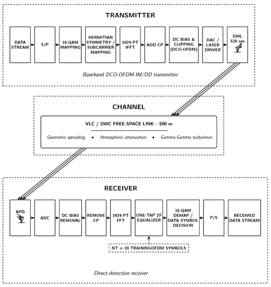
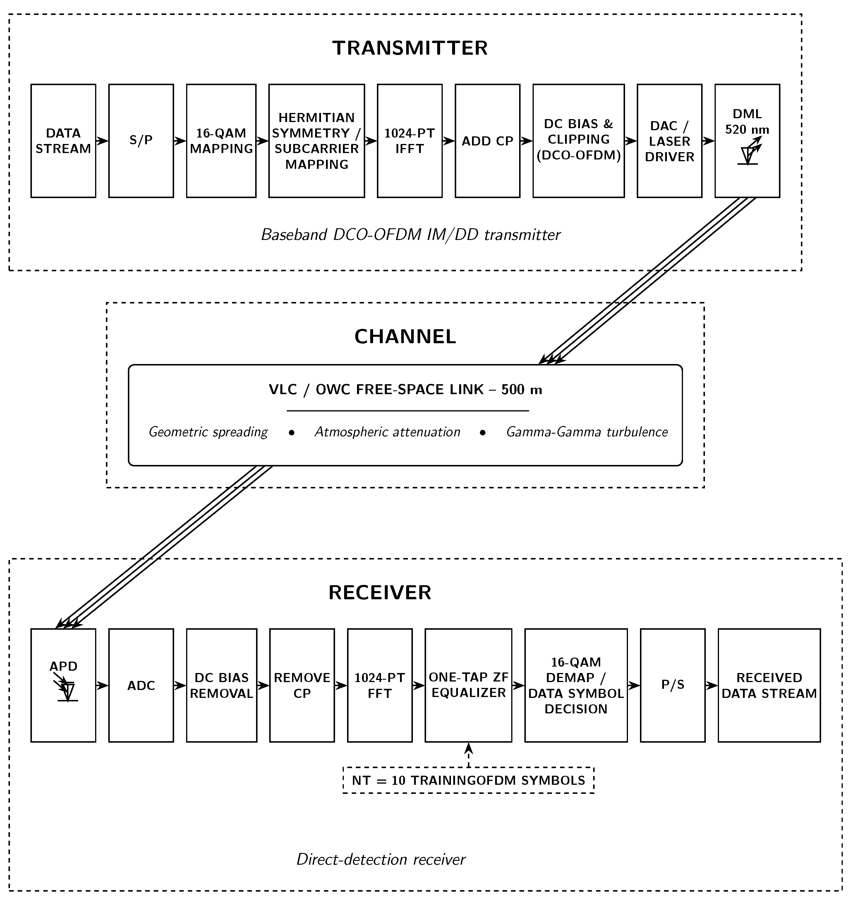
Figure 1 presents the block diagram of the proposed DM-DD-OFDM-VL-OWC system. To design, simulate, and evaluate the system, a custom MATLAB-R2024a-based simulation framework was developed. As illustrated in Figure 1, the overall optical OFDM architecture consists of three main parts: an OFDM transmitter, a VL-OWC channel, and an OFDM receiver. What mainly distinguishes this design from conventional high-speed OWC systems is that it removes the need for both an external Mach–Zehnder modulator (MZM) and an erbium-doped fiber amplifier (EDFA). In standard externally modulated systems, the MZM typically introduces an insertion loss of around 4–6 dB, which can make additional optical amplification necessary. The proposed architecture avoids that “lossy modulator plus high-gain amplifier” configuration and instead adopts a lower-loss direct-coupling approach. As a result, the number of required components is reduced, and the overall system becomes less complex while still maintaining multi-gigabit transmission capability.
Figure 1.
Block diagram of the proposed baseband DCO-OFDM intensity-modulation/direct-detection (IM/DD) DM-DD-OFDM-VL-OWC system. S/P: Serial to Parallel; CP: Cyclic Prefix; DAC: Digital-to-Analog Converter; DML: Directly Modulated Laser; OWC: Optical Wireless Communication; APD: Avalanche Photodiode; ADC: Analog-to-Digital Converter; FFT: Fast Fourier Transform; ZF: Zero Forcing; P/S: Parallel to Serial.
The proposed system is evaluated over a 500 m link. This distance represents a medium-range scenario relevant to large industrial spaces and short inter-building links under clear-weather conditions.
2.1. Optical Link Budget and Path Loss Model
The DM-DD-OFDM-VL-OWC system uses a laser beam to provide wireless connectivity between the transmitter and receiver, with free space serving as the propagation medium. The performance of the link is strongly influenced by geometric beam spreading, atmospheric attenuation, and component losses. For the line-of-sight (LoS) system, the received optical power is expressed as [48]
where and are the receiver and transmitter aperture diameters in meters, respectively, is the full-angle beam divergence in radians, is the transmission range in meters, and is the same range expressed in kilometers. The atmospheric attenuation coefficient is given in dB/km, while , , and denote the transmitter optical loss, receiver optical loss, and additional coupling/alignment losses in dB, respectively. The logarithmic term represents the geometric beam-spreading loss, while the final term accounts for atmospheric attenuation over the link distance.
2.2. OFDM Frame Structure and Data Rate
The system employs a 1024-point IFFT/FFT. To generate a real-valued DCO-OFDM waveform suitable for IM/DD transmission, Hermitian symmetry is imposed in the frequency domain. Consequently, the DC bin and the Nyquist bin are nulled, while the remaining positive-frequency bins carry independent complex QAM symbols; the negative-frequency bins are assigned as their complex conjugates. Using MATLAB one-based indexing, the DC bin () and the Nyquist bin () are set to zero. Each data subcarrier is modulated with 16-QAM ( bits/symbol). The remaining parameters are a cyclic prefix of samples and training OFDM symbols for channel estimation.
With a DAC/ADC sampling rate of , the subcarrier spacing is . The payload data rate, including cyclic-prefix overhead but excluding the negligible training overhead for long data bursts, is calculated as
This corresponds to an approximate gross line rate of 15 Gb/s. The key simulation parameters are summarized in Table 2.
Table 2.
Primary simulation parameters.
2.3. Transmitter
The input bit stream is first mapped onto 16-QAM symbols and then assigned to 511 data-carrying subcarriers. Hermitian symmetry is imposed across the 1024-point IFFT input to obtain a real-valued time-domain DCO-OFDM waveform. A cyclic prefix of 10 samples is then appended to each OFDM symbol. To satisfy the non-negativity requirement of IM/DD transmission, the resulting waveform is DC-biased to approximately four times its RMS value, and any remaining negative excursions are clipped at zero. This clipping corresponds to the lower limit of the optical intensity modulation and keeps the signal compatible with direct optical intensity modulation, although it introduces a controlled level of clipping distortion.
For interpretation of the nonlinear penalties, zero clipping and laser-related distortion are distinguished by their physical origin. Zero clipping is applied after DC biasing and removes the residual negative samples; it therefore represents a deterministic amplitude-domain distortion intrinsic to DCO-OFDM. Laser-induced amplitude distortion occurs after electrical-to-optical conversion and is associated with the finite dynamic range and dynamic response of the directly modulated device. Laser chirp, by contrast, represents a variation in the instantaneous optical frequency rather than an additional clipping mechanism.
At the transmitter, a commercial InGaN green laser diode with a center wavelength of 520 nm is used as the optical source. Compared with diode-pumped solid-state (DPSS) green lasers, which are generally more limited for high-speed direct modulation, InGaN laser diodes are better suited to high-speed current modulation. Experimental studies on GaN/InGaN visible laser diodes have reported multi-gigahertz modulation bandwidths and multi-gigabit-per-second data transmission using formats such as OOK and QAM-OFDM [6,7,8]. For the baseline results presented in Section 3.1 and Section 3.2, the directly modulated laser (DML) is assumed to provide sufficient bandwidth to cover the full one-sided OFDM spectrum of approximately 3.75 GHz. A more bandwidth-limited case, with , is examined separately in Section 3.9.
The DML is represented at the system level using representative semiconductor-laser parameters, including a linewidth-enhancement factor , an adiabatic chirp factor of , and an optical linewidth of 10 MHz. These parameters characterize the assumed laser response under the adopted numerical conditions rather than a device-calibrated prediction for a particular commercial laser. Because the propagation path is free space and chromatic dispersion is negligible, the conversion of laser chirp into received-intensity distortion is expected to remain limited. The cyclic prefix primarily protects against linear time-dispersive distortion and does not directly compensate laser chirp. Furthermore, because information is detected through optical intensity rather than optical phase, the assumed linewidth is expected to have only a limited influence under the present IM/DD link assumptions.
A Volterra-series formulation could provide a complementary description of nonlinear distortion with memory when its kernels are identified for the specific laser device. Such experimentally calibrated modeling is therefore identified as a direction for future work.
2.4. Channel
The optical DCO-OFDM signal is transmitted over a 500 m free-space VL-OWC link. Both the transmitter and receiver use circular apertures with a diameter of 5 cm. The 5 cm receiver aperture is retained as the baseline case, while 10 and 15 cm receiver apertures are evaluated in the sensitivity analysis. A Gaussian beam profile is assumed, with a fixed full-angle divergence of 2 mrad, consistent with the link-budget model in Equation (1). The channel includes deterministic geometric beam spreading and clear-weather atmospheric attenuation, while atmospheric turbulence is introduced separately using the Gamma–Gamma fading model. Probabilistic pointing displacement is also considered separately to represent residual angular jitter and beam misalignment.
Although recent developments in metasurface-based optics have enabled more advanced beam-shaping strategies, including non-diffracting Bessel beams for full-space coverage [49], the present work adopts a simpler static-divergence model. This choice keeps the transmitter architecture less complex while still providing sufficient link margin for the intended transmission scenario. The added pointing-error analysis quantifies the receiver-aperture and tracking requirements under residual alignment jitter.
2.5. Receiver
At the receiver, the avalanche photodiode (APD) converts the incoming optical intensity into a photocurrent. To compensate for the geometric path loss over the 500 m link, a high-sensitivity APD is used instead of a conventional PIN photodiode. At 520 nm, silicon photodiodes can provide an intrinsic responsivity on the order of 0.45 A/W, while the APD additionally provides internal multiplication through the gain factor M. In the present simulation, the APD is modeled with an intrinsic responsivity of 0.45 A/W and a multiplication factor of approximately , giving an effective photocurrent responsivity of about 1.1 A/W. This internal gain helps maintain sufficient receiver SNR without the need for optical pre-amplification such as an EDFA.
The APD is assumed to operate within its linear multiplication region. Receiver impairments are represented at the system level through the adopted SNR-equivalent noise parameterization. A device-specific decomposition into shot noise, thermal noise, background-light-induced current, avalanche-gain variation, and transimpedance-amplifier noise is not independently resolved in the present numerical results. Likewise, APD saturation and nonlinear front-end distortion are not included as separate impairment mechanisms. These effects should be quantified experimentally for the selected APD–TIA front end, particularly because the instantaneous peaks of a high-PAPR OFDM waveform may approach the receiver dynamic-range limit even when the average received power is moderate.
After direct detection, the received electrical signal is sampled by an ADC, the DC bias is removed, the cyclic prefix is discarded, and a 1024-point FFT is applied to recover the frequency-domain subcarriers. Channel distortion is then compensated using one-tap zero-forcing equalization, with channel estimation based on pilot OFDM symbols, before 16-QAM demapping and bit recovery are performed.
3. Simulation Results and Discussion
This section presents the numerical results for the proposed DM-DD-OFDM-VL-OWC system. The analysis first evaluates baseline static line-of-sight BER and Q-factor performance, then examines beam-divergence sensitivity, probabilistic pointing error, and receiver-aperture size. Analytical link-budget verification is distinguished from the contextual comparison with previously published experiments. The study is then extended to adverse-weather attenuation, Gamma–Gamma turbulence, and atmospheric-fading outage probability. Finally, adaptive bit loading is investigated for bandwidth-limited DML operation.
3.1. Baseline BER and Q-Factor Performance
In this simulation, OSNR is treated as a receiver-side SNR-equivalent parameter, defined as the ratio between the average detected DCO-OFDM signal power on the active data-bearing subcarriers and the added white receiver-noise power over the simulated OFDM signal bandwidth, rather than as an optical OSNR referenced to a fixed optical noise bandwidth.
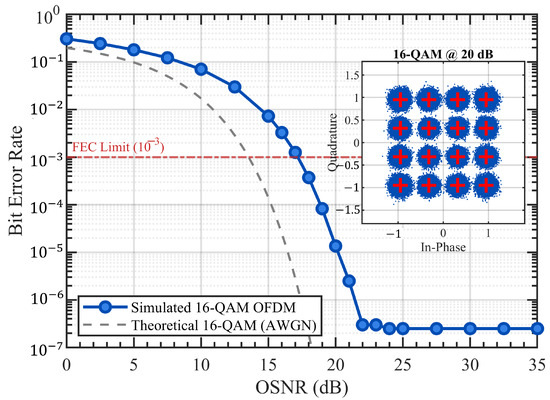
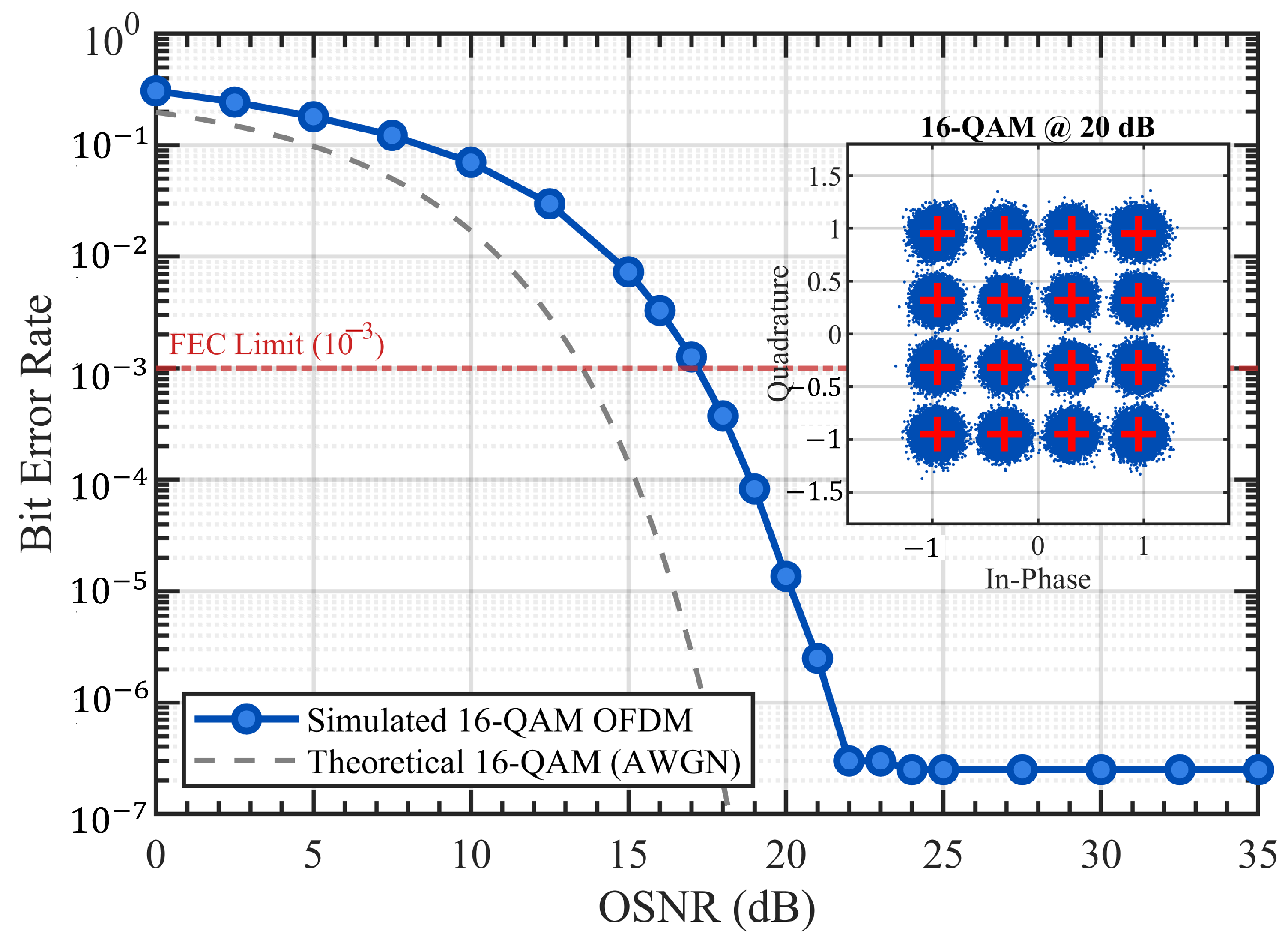
Figure 2 shows the simulated BER performance of the proposed DM-DD 16-QAM OFDM system as a function of OSNR. Each BER value is estimated from transmitted bits. The simulated curve crosses the forward-error-correction (FEC) threshold of at an OSNR of approximately 17 dB. The simulated BER follows the general waterfall trend of the theoretical 16-QAM AWGN reference but shows an implementation penalty due to clipping, laser nonlinearity, and direct-modulation impairments. At higher OSNR values, the BER improvement gradually slows because the system becomes increasingly limited by DCO-OFDM clipping and nonlinear distortion rather than additive noise alone. Since each BER point is estimated using transmitted bits, BER values near the lower plotting limit should be interpreted as simulation-limited rather than exact error-floor measurements. The inset constellation at 20 dB OSNR nevertheless shows clear separation of the 16-QAM symbols near the FEC operating point.
Figure 2.
BER performance versus OSNR for the proposed 16-QAM DCO-OFDM VL-OWC link over 500 m under static LoS conditions. The FEC threshold and theoretical 16-QAM AWGN reference are included for comparison.
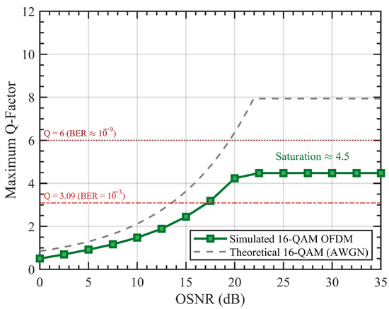
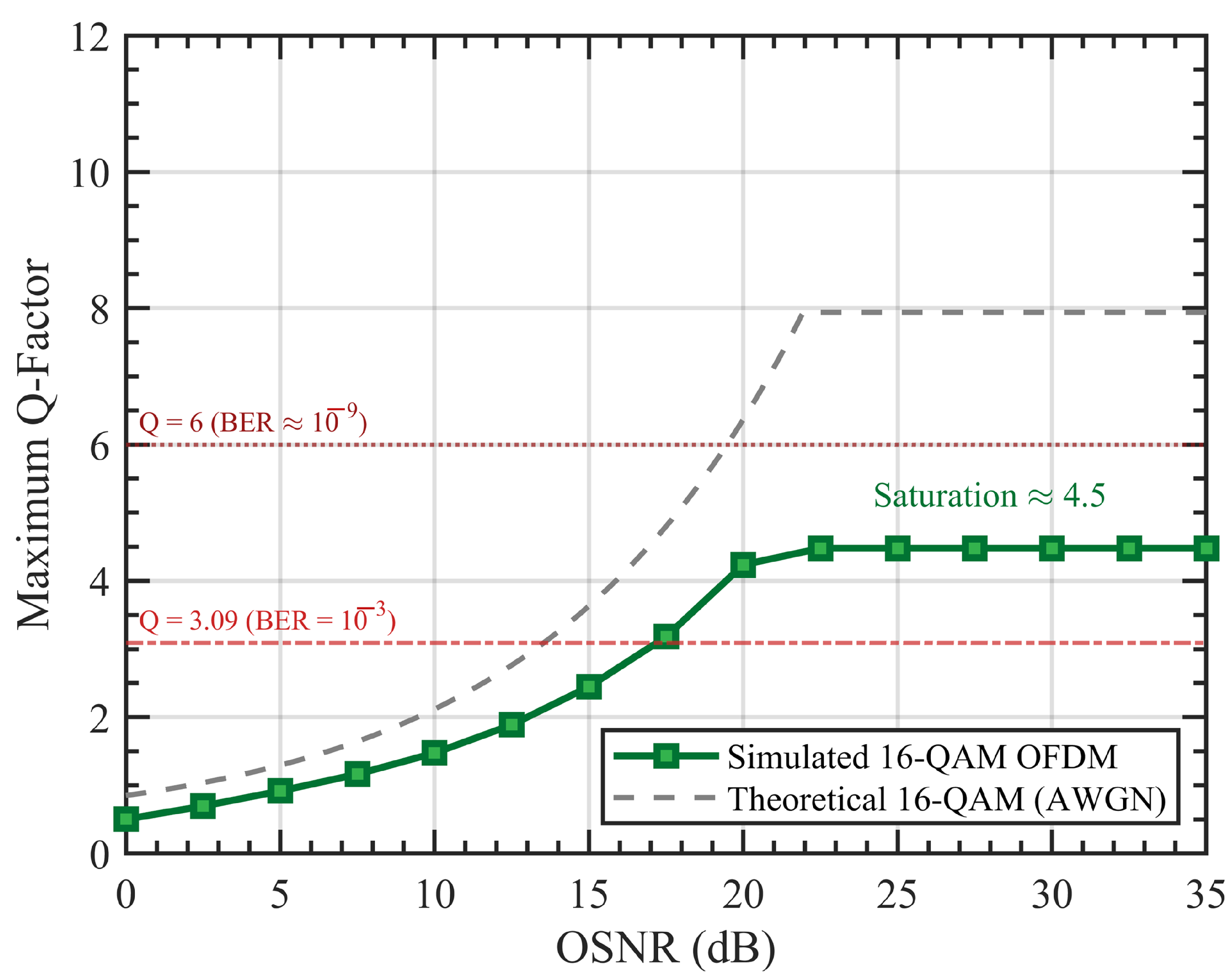
Figure 3 shows the maximum Q-factor as a function of OSNR for the proposed 16-QAM DCO-OFDM link. Although BER remains the main performance metric in this work, the Q-factor is interpreted as a complementary Gaussian-equivalent signal-quality indicator and is used alongside BER to illustrate the transition from noise-limited to distortion-limited operation.
Figure 3.
Maximum Q-factor versus OSNR for the proposed 16-QAM DCO-OFDM link, showing the transition from noise-limited to distortion-limited operation.
As shown in Figure 3, the Q-factor increases with OSNR and reaches the FEC-relevant reference value of , corresponding to a BER-equivalent value of approximately under the Gaussian-equivalent Q-factor convention, at around 17 dB OSNR. This agrees well with the BER behavior observed in Figure 2. At lower OSNR values, the increase in Q-factor reflects improved effective signal quality as additive noise becomes less dominant. Beyond about 20 dB OSNR, however, the simulated Q-factor no longer follows the ideal 16-QAM AWGN trend and begins to level off near 4.5. This flattening indicates that the link is no longer limited primarily by additive noise, but increasingly by signal-dependent distortion associated with the DCO-OFDM waveform and the finite dynamic range or nonlinear response of the directly modulated laser.
More specifically, the high PAPR of the OFDM signal can produce clipping at the lower limit imposed by zero-clipping and compression at the upper end of the laser modulation response. These effects reduce the effective constellation spacing and create a distortion floor, preventing further improvement in Q-factor even as OSNR continues to increase. In this sense, Figure 3 supports the same physical interpretation as Figure 2: the proposed system is mainly noise-limited at low-to-moderate OSNR and becomes distortion-limited at higher OSNR.
To separate the physical origins of the nonlinear impairments, the curves in Figure 2 and Figure 3 are interpreted in terms of clipping, laser-related distortion, and receiver assumptions. The curves represent the combined response of the adopted system model and do not assign a separate numerical penalty to each nonlinear mechanism. The individual contributions can nevertheless be distinguished physically. First, residual negative excursions after DC biasing are removed by zero clipping, producing an amplitude-domain distortion whose severity depends on the bias level and OFDM sample distribution. Second, the high-PAPR electrical drive can excite the finite dynamic range and nonlinear response of the directly modulated laser, producing signal-dependent amplitude distortion in addition to the clipping contribution. Third, laser chirp changes the instantaneous optical frequency; in the present dispersion-free free-space path, its direct conversion into received-intensity distortion is expected to be weaker than the amplitude-domain effects. Finally, the APD is assumed to remain in its linear operating region, so APD saturation and nonlinear front-end distortion are not included in the plotted curves. Consequently, the present results support a qualitative separation of the impairment mechanisms but should not be interpreted as a quantitative impairment-by-impairment penalty budget. Obtaining such a budget would require a device-calibrated ablation study in which clipping, laser amplitude nonlinearity, chirp, and receiver saturation are independently enabled and disabled under otherwise identical conditions.
3.2. Beam Divergence Sensitivity
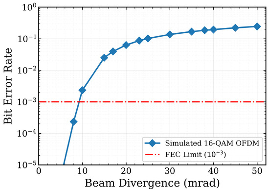
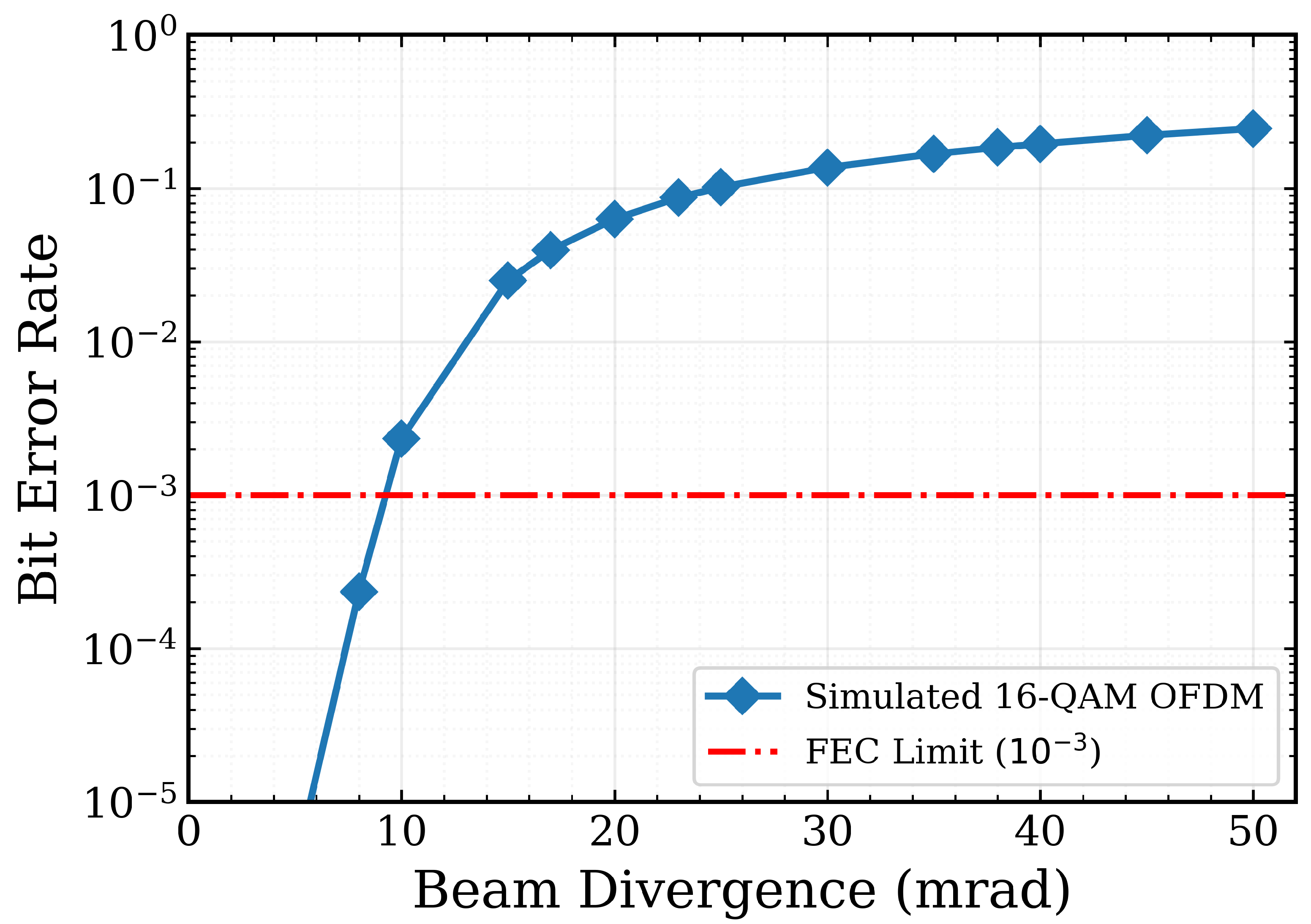
Figure 4 shows the BER as a function of beam divergence angle over a 500 m link under a 20 dB OSNR reference condition. The BER remains below the FEC threshold of for divergence angles up to approximately 9 mrad, after which the performance degrades rapidly because of the increased geometric spreading loss described by Equation (1).
Figure 4.
BER performance as a function of beam divergence angle at 20 dB OSNR over a 500 m link.
This behavior reflects the sensitivity of the received-power margin to beam spreading and indicates the importance of adequate beam collimation. Random beam displacement and angular pointing errors are analyzed separately in Section 3.3.
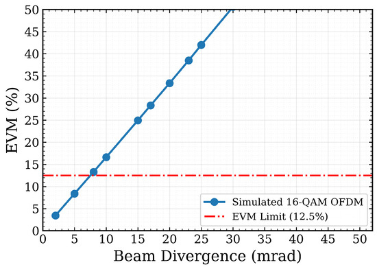
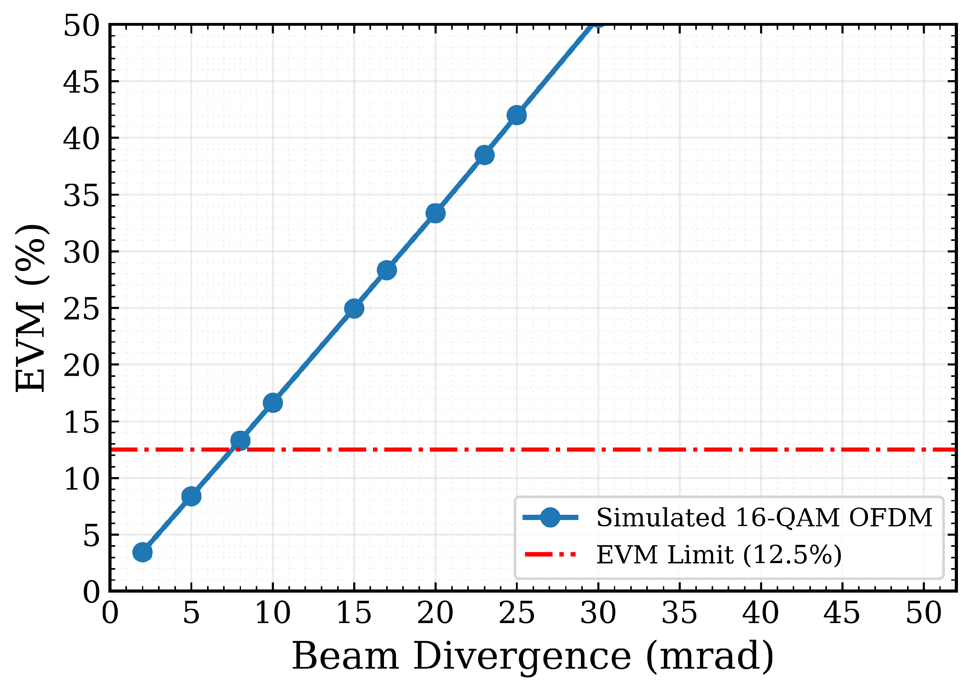
Figure 5 shows the Error Vector Magnitude (EVM) as a function of beam divergence angle. EVM quantifies the root-mean-square deviation of the received constellation symbols from their ideal positions, expressed as a percentage of the reference constellation amplitude. As the beam divergence increases, the EVM rises monotonically because the received signal quality is degraded by increased geometric spreading loss. The EVM remains below the 12.5% reference limit for divergence angles up to approximately 7–8 mrad. This 12.5% value is adopted here as a practical 16-QAM signal-quality benchmark, consistent with commonly used wireless-system EVM limits, rather than as a strict VL-OWC-specific requirement. The fact that the EVM limit is reached slightly before the BER exceeds the FEC threshold provides a useful design margin: the EVM metric indicates impending signal degradation before the BER criterion is violated.
Figure 5.
EVM performance as a function of beam divergence angle, showing the 12.5% 16-QAM reference limit.
3.3. Probabilistic Pointing Error and Receiver-Aperture Sensitivity
The divergence sweep in Figure 4 and Figure 5 assumes that the beam remains centered on the receiver. Following the standard zero-boresight pointing-error model [38,50], the horizontal and vertical receiver-plane displacements are represented by independent zero-mean Gaussian components. Expressing these displacements in terms of the corresponding small angular errors gives
where and are the instantaneous angular pointing errors in the horizontal and vertical directions, respectively, is their common per-axis standard deviation in radians, L is the link distance in meters, and r is the resulting radial displacement of the beam center at the receiver plane in meters. The expression for r uses the small-angle approximation, with the horizontal and vertical receiver-plane displacements given by and , respectively. Because both angular-error components are zero mean, is also the per-axis RMS angular jitter, whereas the RMS magnitude of the two-dimensional angular error is . The model therefore corresponds to the zero-boresight case.
Under these assumptions, the radial displacement r follows a Rayleigh distribution [38] with scale parameter
where is the standard deviation of the corresponding transverse displacement in either Cartesian direction at the receiver plane.
For a circular receiver aperture of radius
where is the receiver-aperture diameter. For consistency with the geometric spot-diameter model in Equation (1), the equivalent Gaussian beam radius at the receiver plane is approximated as
where is the transmitter-aperture diameter and is the fixed full-angle beam divergence in radians. The quantity corresponds to the divergence parameter used in Equation (1) and should not be confused with the random pointing-error components and .
Using the finite-aperture Gaussian pointing-loss approximation developed in [38], the fraction of optical power collected under a radial displacement r is
where is the dimensionless pointing-loss coefficient, is the fraction of optical power collected when the beam is perfectly centered, is the error function, and v is a dimensionless aperture parameter. The equivalent beam radius , which accounts for the finite receiver aperture, is given by [38]
The normalized pointing-loss coefficient is defined as
Accordingly, the received power under pointing displacement, expressed in dBm, is
where is the centered received power calculated from Equation (1) for the considered receiver-aperture diameter.
Pointing-induced outage is defined as
where is the receiver-sensitivity reference used in the pointing-outage analysis. Let denote the radial displacement at which . The corresponding normalized pointing-loss threshold is
and the threshold displacement is
Using the complementary cumulative distribution function of the Rayleigh radial-displacement model [38], the zero-boresight pointing-outage probability is
where denotes the pointing-induced outage probability and denotes probability.
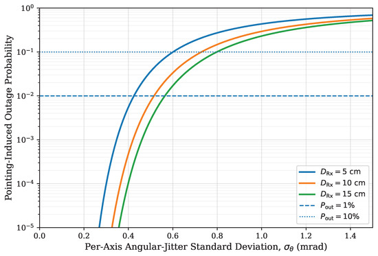
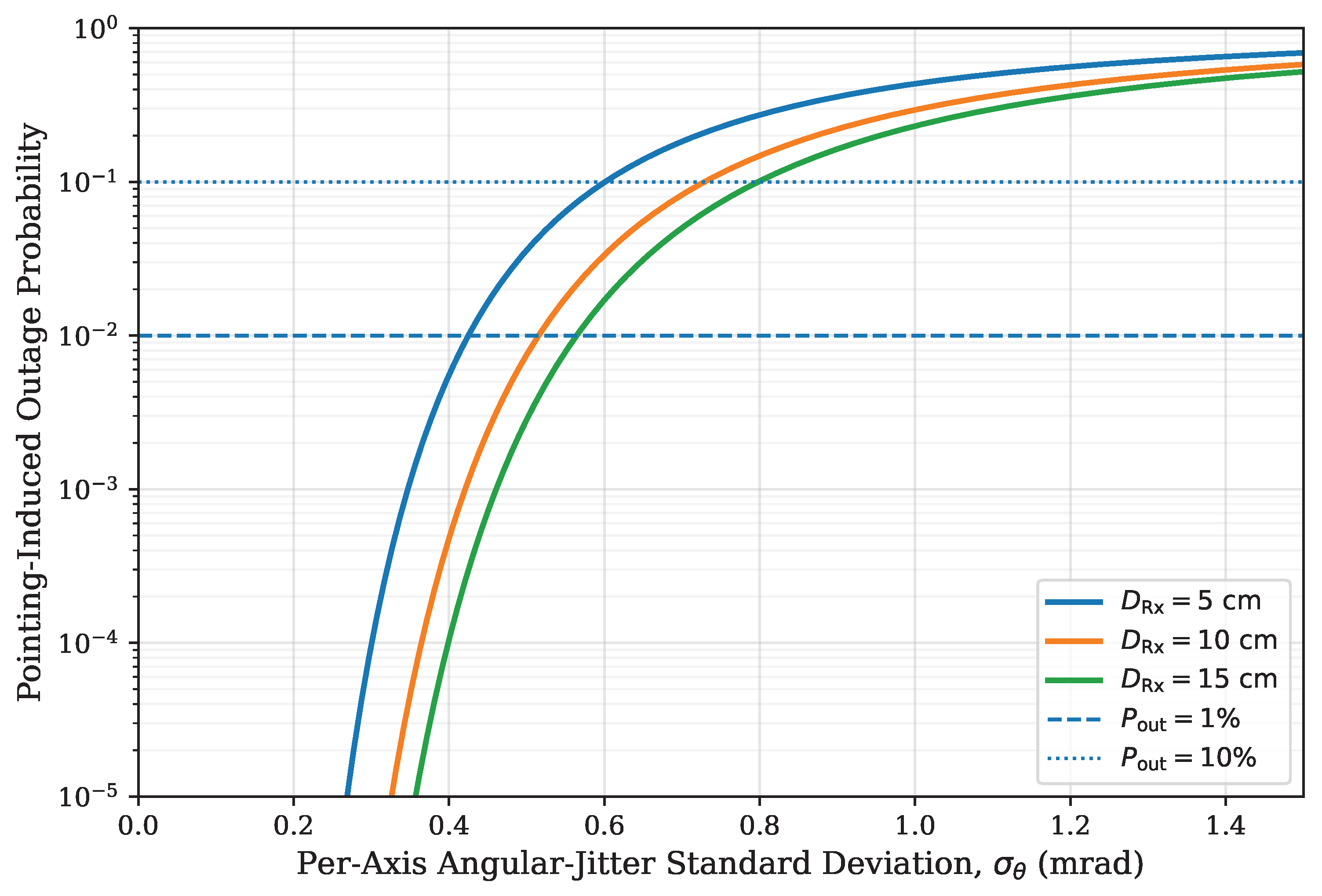
Figure 6 compares the pointing-induced outage probability for receiver-aperture diameters of 5, 10, and 15 cm as a function of the per-axis angular-jitter standard deviation, . The 5 cm baseline reaches the 1% outage level at . Increasing the aperture diameter to 10 and 15 cm raises this limit to approximately 0.515 and 0.564 mrad, respectively. The improvement is driven primarily by the larger centered received-power margin, with an additional contribution from the increased tolerance to radial beam displacement. This sensitivity analysis isolates pointing-induced loss; atmospheric turbulence is evaluated separately in Section 3.7. Nevertheless, the curves show that increasing the aperture alone does not eliminate alignment sensitivity. For per-axis angular-jitter standard deviations approaching 1 mrad, the outage probability becomes substantial for all three apertures. These results support the use of a larger receiver aperture where size and cost permit, while indicating that outdoor deployment may require an active acquisition, pointing, and tracking subsystem.
Figure 6.
Pointing-induced outage probability versus per-axis angular-jitter standard deviation for 5, 10, and 15 cm receiver apertures over the 500 m design link. Outage is defined as received optical power below the adopted dBm receiver-sensitivity reference.
3.4. Analytical Link-Budget Verification
For the power-budget analysis, the received optical power at the APD is calculated using Equation (1), which accounts for transmitted optical power, geometric beam spreading, atmospheric attenuation, and component losses. To avoid unit ambiguity, the propagation range is expressed using two equivalent quantities: in meters for the geometric beam-spreading term and in kilometers for the atmospheric attenuation term. In this model, is treated as the full-angle beam divergence used in the geometric spot-diameter term .
From Table 2, dBm, cm, mrad rad, dB/km, dB, and dB. For the 500 m reference link, m and km. Therefore,
The received optical power at 500 m is then
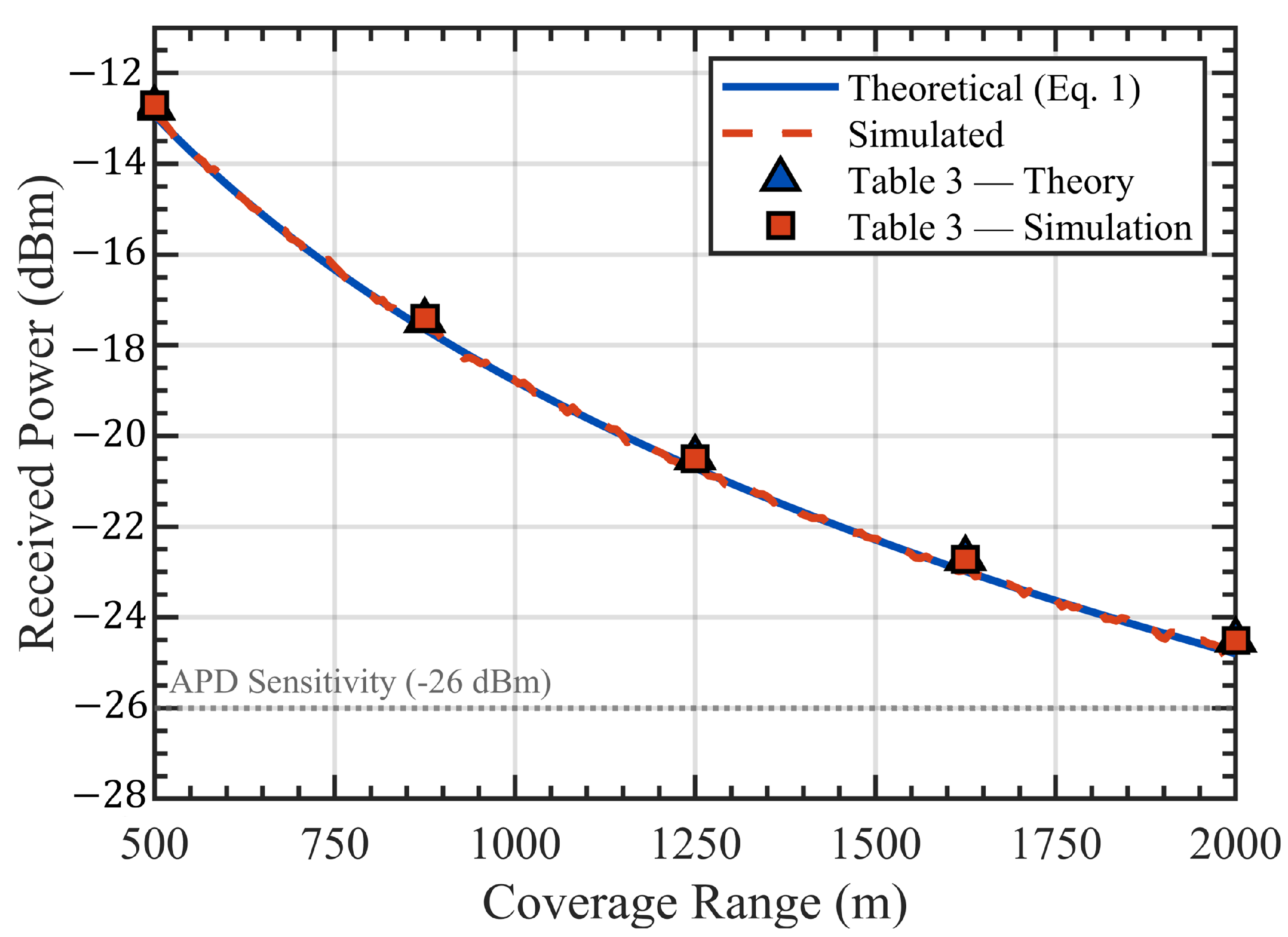
The same procedure is applied for the other link ranges listed in Table 3.
Table 3.
Comparison between theoretically calculated and simulated received optical power values across different link ranges.
Table 3 compares the received optical power obtained from the theoretical link-budget model in Equation (1) with the MATLAB simulation results. The theoretical and simulated values show close agreement over the considered link range. The small residual difference of approximately 0.2–0.3 dB is attributed to numerical rounding, model implementation details, and component-level assumptions not explicitly included in the closed-form link-budget expression. Since the simulated received powers are slightly higher than the theoretical values, this difference should not be described as an implementation loss. Instead, the close agreement confirms that the implemented optical propagation model is consistent with the analytical link-budget calculation.
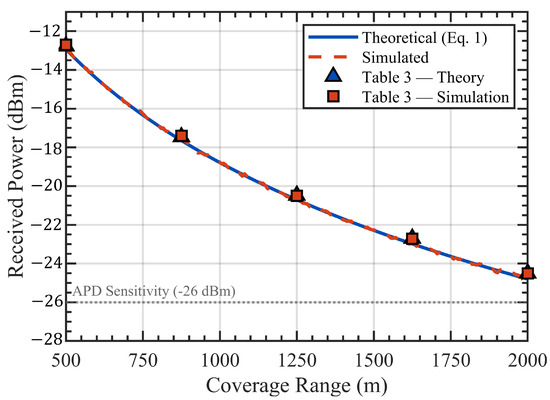
Figure 7 illustrates the received optical power as a function of link range. The APD sensitivity level of dBm is included as a receiver-margin reference. At 500 m, the theoretical received power of approximately dBm provides a link margin of about 13.1 dB relative to the APD sensitivity. At 2 km, the theoretical received power decreases to approximately dBm, leaving a smaller margin of about 1.2 dB.
Figure 7.
Theoretical and simulated received optical power versus link range for the proposed VL-OWC link. The APD sensitivity level is included as a receiver-margin reference.
3.5. Model Verification and Comparison with Reported Experiments
The numerical results are evaluated on two separate tiers. First, the deterministic free-space propagation model is verified by comparing the received-power values generated numerically with those obtained from the closed-form link-budget expression in Equation (1). As shown in Figure 7 and Table 3, the two calculations agree within approximately 0.2–0.3 dB over the considered link distances. This agreement confirms the consistent implementation of geometric beam spreading, atmospheric attenuation, and the specified component losses. It does not, however, evaluate hardware-dependent effects such as laser dynamics, detector noise, background illumination, alignment fluctuations, or atmospheric variability.
Table 4 serves a different purpose. It compares the simulated performance of the proposed system with representative experimental demonstrations of GaN-based visible-laser communication. These reported experiments were conducted over approximately 0.15–5 m and used different wavelengths, modulation formats, receivers, equalization methods, and hardware bandwidths. They therefore provide useful evidence of the achievable data rates of visible laser diodes, but they cannot establish the accuracy of the predicted performance over the 500 m link. Accordingly, the comparison is used to position the proposed system relative to the current experimental state of visible-laser transmission rather than to infer direct scalability from laboratory distances to the medium-range link considered here.
Table 4.
Comparison of the proposed system with representative visible-laser experiments.
Several implementation factors can cause measured performance to deviate from the present numerical predictions. At the transmitter, laser-driver noise, bias drift, device-to-device variation in DML bandwidth and nonlinear response, and temperature-dependent changes in optical power, threshold current, chirp, and modulation efficiency can alter the launched waveform. The electrical interface introduces additional penalties through finite DAC and ADC bandwidth, quantization, sampling-clock jitter, synchronization error, and limited analogue front-end linearity. At the receiver, device-specific uncertainty in APD shot noise, thermal noise, ambient-light-induced background current, avalanche gain, and possible APD or transimpedance-amplifier saturation can reduce the effective SNR relative to the system-level assumptions. Further deviations can arise from connector and coupling losses, aperture truncation, lens contamination or wetting, residual static misalignment, building sway, time-varying pointing jitter, weather-dependent attenuation and turbulence, and imperfect channel estimation and equalization. These effects may interact rather than contribute as independent additive penalties, so their net impact should be established through measurements on a specific transmitter, receiver, and outdoor path.
A rigorous experimental validation procedure would first calibrate the transmitter, receiver, and propagation parameters using a controlled short-range prototype and compare the measured BER, received power, and nonlinear response with the corresponding simulation results. The calibrated model could then be evaluated over progressively longer paths while recording atmospheric attenuation, turbulence strength, beam wander, and pointing jitter. Such measurements would provide the experimental basis needed to assess the accuracy of the present numerical predictions under realistic outdoor operating conditions.
3.6. Adverse-Weather Attenuation Sensitivity
The atmospheric attenuation coefficient used in the preceding results is retained as the clear-air baseline, where denotes the clear-air power-attenuation coefficient per unit distance. The associated clear-air loss is already included in the centered received power . To quantify the additional deterministic loss caused by haze, fog, and rain without changing the other system parameters, a separate weather sensitivity analysis is performed using Recommendation ITU-R P.1814-1 [51].
For suspended particles, including aerosols, haze, fog, and a first-order visibility-based representation of dust, the specific attenuation is
where is the suspended-particle specific attenuation in , is the visibility in kilometres defined using the 2% irradiance threshold, is the operating wavelength in micrometres, and is the reference wavelength. The quantity q is the dimensionless visibility-dependent wavelength exponent given by
The corresponding additional suspended-particle path loss is
where is expressed in decibels and L is the propagation distance in kilometres. The present analysis uses and . For comparison with the conventional meteorological optical range defined at the 5% threshold, ITU-R P.1814-1 gives
where is the corresponding 5%-threshold visibility.
For rain, the specific attenuation is represented as
where is the rain-specific attenuation, R is the rain rate in , and k and a are empirical coefficients determined by the adopted raindrop-size distribution. The distribution-shape parameter is denoted by ; the central case is used here, giving and . These coefficients are adopted at 520 nm as a first-order wavelength-independent sensitivity approximation; experimental calibration would be required for a device-specific visible-light rain model. Under the conservative uniform-path approximation, the additional rain loss is
where is expressed in decibels. The complete ITU-R procedure additionally includes rain-cell path-reduction and forward/multiple-scattering corrections, so site-specific attenuation may be lower than this first-order estimate.
To express the haze/fog and rain cases using common notation, the generic weather-specific attenuation is defined as
and the corresponding additional weather loss is denoted by , where for suspended particles and for rain.
The received power and remaining receiver margin under a weather condition are calculated as
where is the weather-affected received power in dBm, is the centered clear-air received power at 500 m, is the additional weather loss in dB, is the remaining receiver-power margin in dB, and is the adopted receiver-sensitivity reference.
Table 5 shows that haze/fog conditions with – retain approximately 4.3–8.7 dB of receiver-power margin. The margin decreases to approximately 0.8 dB at and becomes negative at . Under the adopted model, the receiver-sensitivity boundary occurs at , corresponding to a conventional meteorological optical range of approximately . Within the selected weather cases and adopted first-order models, low-visibility haze/fog is therefore more restrictive than the evaluated rain rates.
Table 5.
Adverse-weather sensitivity for the 500 m, 520 nm design link. The clear-air attenuation of is already included in . The quantities and represent the additional weather-specific attenuation and the corresponding additional loss over the 500 m path, respectively. Haze/fog inputs use the 2%-threshold visibility .
For the selected rain rates, the receiver-power margin decreases more gradually. Rain rates of 5, 25, and 50 mm/h leave approximately 11.3, 7.9, and 5.1 dB of margin, respectively. At 100 mm/h, the conservative uniform-path approximation leaves approximately 0.55 dB, while the receiver-sensitivity boundary occurs near 107 mm/h. These values should be interpreted as first-order sensitivity estimates at 520 nm rather than as device-specific visible-light rain predictions. Recent visible-laser experiments have likewise demonstrated measurable communication degradation in artificial fog and rain channels, including at wavelengths close to that considered here [52,53].
These values are deterministic link-margin estimates rather than combined BER or outage predictions. They assume a uniform weather condition over the 500 m path and do not simultaneously include Gamma–Gamma scintillation, pointing jitter, wet-window loss, or time-varying background illumination. For campus, industrial, and disaster-recovery deployments, local visibility and rainfall statistics should therefore be used to determine availability. Practical mitigation may include additional fade margin, adaptive modulation and bit loading, aperture enlargement, automatic power or rate control, weather monitoring, and a redundant RF or fibre path. Dust and sand may be represented through the visibility-based suspended-particle model as a first-order estimate, but accurate prediction in arid environments requires local particle-size and concentration measurements.
3.7. Atmospheric Turbulence Analysis
Although the preceding results establish the baseline behavior of the proposed DM-DD-OFDM-VL-OWC link under an ideal static channel, practical outdoor operation is also influenced by atmospheric turbulence. In particular, turbulence introduces random irradiance fluctuations, commonly referred to as scintillation, which can noticeably affect link reliability. To capture this behavior, the atmospheric channel is modeled using the widely adopted Gamma–Gamma (GG) distribution, which is commonly used for weak-to-strong turbulence conditions. In this model, the received irradiance fading coefficient h is normalized such that . Its probability density function is expressed as
where and are the large-scale and small-scale scintillation parameters, respectively, is the Gamma function, and is the modified Bessel function of the second kind. The subscripts in and are used to avoid confusion with the atmospheric attenuation coefficient used in the link-budget equation. For a plane-wave propagation model, the Rytov variance is given by
where is the refractive-index structure parameter, is the optical wavenumber, and L is the propagation distance.
An important practical consideration is aperture averaging. When the receiver aperture diameter is larger than the Fresnel-related scale , the received irradiance fluctuations are spatially averaged over the aperture, reducing the effective scintillation strength. For the proposed system, cm, nm, and m. Therefore,
Since , aperture averaging is expected to noticeably suppress scintillation.
Here, denotes the aperture-averaging factor, which represents the multiplicative reduction applied to the point-receiver Rytov variance, or scintillation strength, when the received irradiance is spatially averaged over a finite circular aperture.
Using the simplified approximation adopted in this work,
Thus, the effective turbulence strength used to obtain the Gamma–Gamma parameters is
For the 5 cm baseline aperture, this approximation gives an approximately one-order-of-magnitude reduction relative to the corresponding point-receiver value.
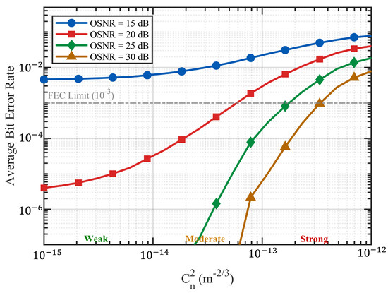
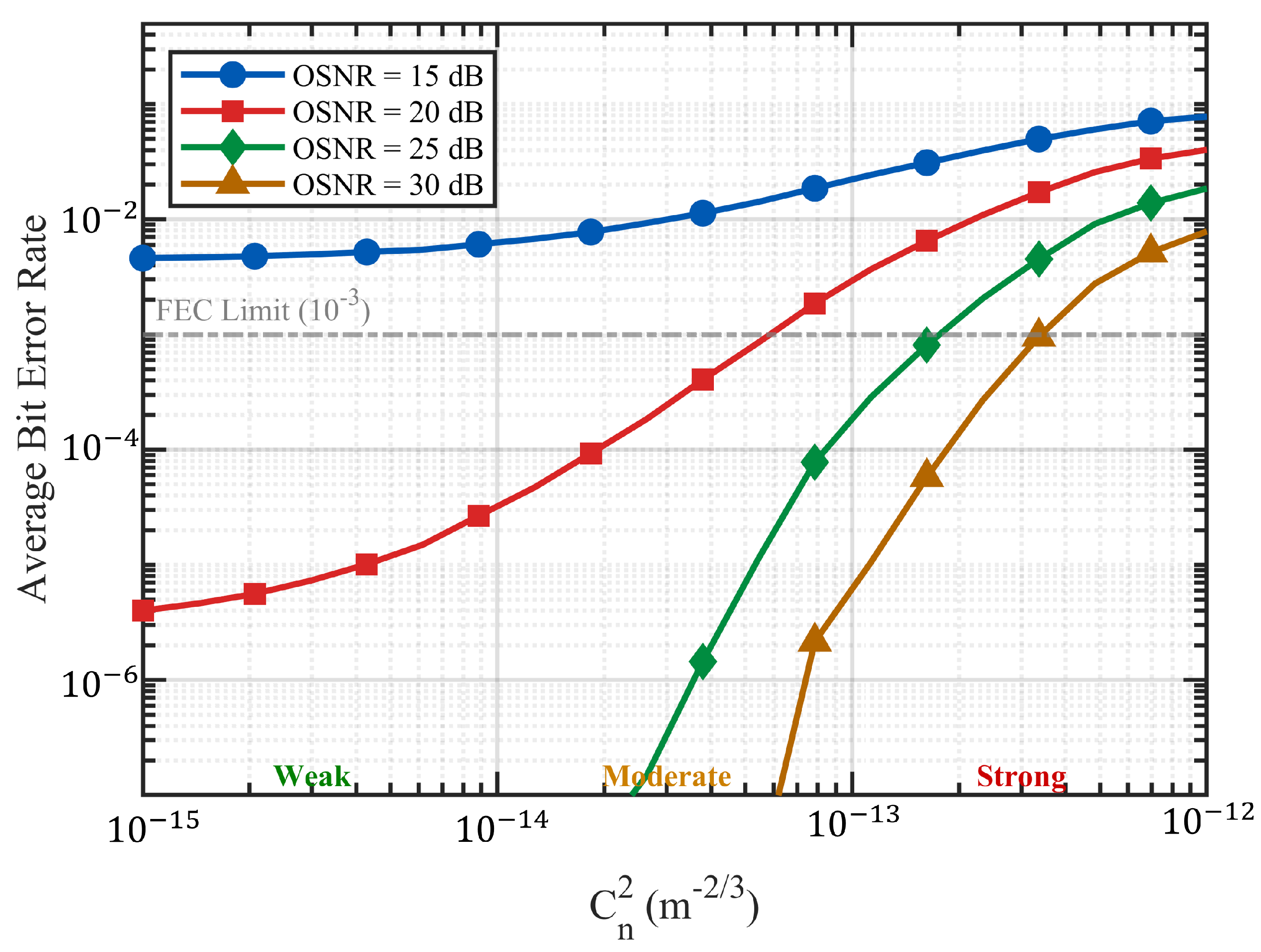
Figure 8 presents the average BER as a function of for four average OSNR values: 15, 20, 25, and 30 dB. The BER values are computed by averaging the instantaneous 16-QAM BER over 50,000 Gamma–Gamma fading realizations. The results reveal several key findings:
Figure 8.
Average BER as a function of atmospheric turbulence strength () under Gamma–Gamma fading for four OSNR levels.
- For weak turbulence ( m−2/3), the BER varies only slightly with increasing turbulence strength, indicating that scintillation-induced degradation is limited in this regime. The BER performance in this region is mainly determined by the available OSNR, with the 15 dB case remaining above the FEC threshold while higher OSNR values provide substantially lower BER.
- At dB, the system maintains up to approximately m−2/3, after which the BER begins to exceed the FEC threshold.
- For stronger turbulence levels, particularly as approaches m−2/3, even the 30 dB OSNR case exceeds the FEC limit. This indicates that additional mitigation strategies, such as spatial diversity, adaptive coding, or stronger FEC, would be required for reliable operation under severe turbulence.
3.8. Outage Probability Analysis
To further characterize the reliability of the proposed system under atmospheric turbulence, we compute the outage probability , defined as the probability that the instantaneous BER exceeds the FEC threshold of . Equivalently, since the instantaneous BER decreases monotonically with received SNR, the outage probability can be written as
where is the instantaneous received SNR and is the effective SNR threshold corresponding to . Based on the baseline BER result in Figure 2, this threshold is approximately dB for the proposed 16-QAM DCO-OFDM link, including the implementation penalty associated with clipping, laser nonlinearity, and direct-modulation impairments.
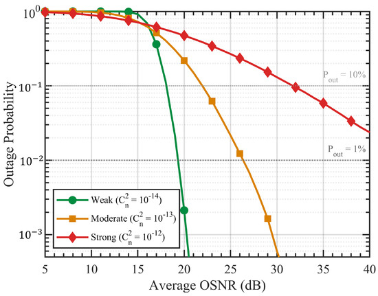
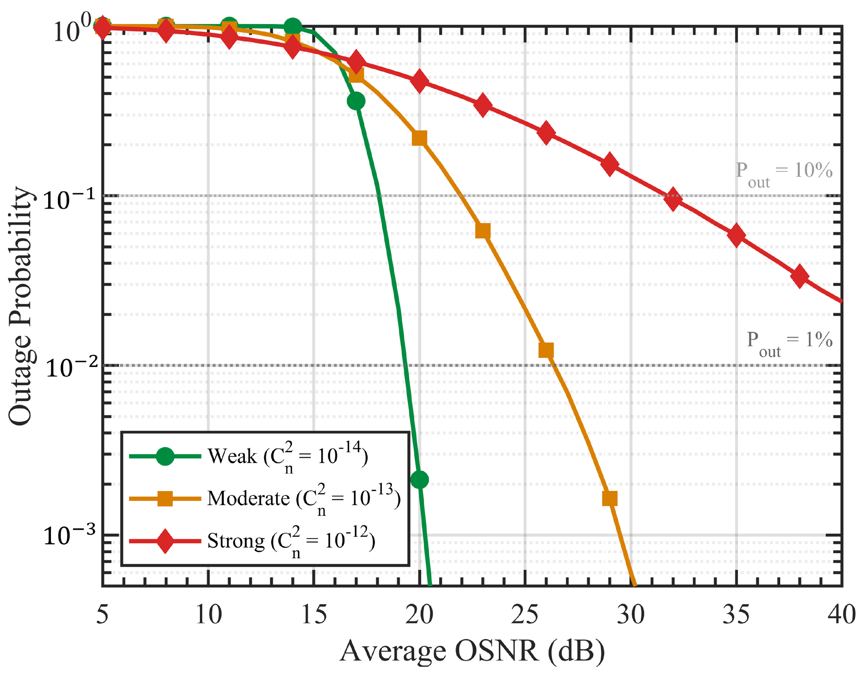
Figure 9 presents the outage probability versus average OSNR for three turbulence regimes: weak ( m−2/3), moderate ( m−2/3), and strong ( m−2/3). The results are computed over 50,000 Monte Carlo fading realizations. Key observations include:
Figure 9.
Outage probability, defined as , versus average OSNR under weak, moderate, and strong Gamma–Gamma turbulence regimes. The 10% and 1% outage reference levels are shown as dotted horizontal lines.
- Under weak turbulence, the system achieves at an average OSNR of approximately 19–20 dB. The steep waterfall behavior indicates that, in this regime, only a small additional OSNR margin above the static-channel threshold is required.
- Under moderate turbulence, achieving requires approximately 26–27 dB average OSNR. This corresponds to an additional penalty of about 7–8 dB relative to the weak-turbulence case, or roughly 10 dB relative to the nominal 17 dB static-link threshold.
- Under strong turbulence, the outage probability decreases much more slowly with increasing OSNR because of the deeper fading events associated with the Gamma–Gamma distribution. Even at 40 dB average OSNR, the outage probability remains above 2%, suggesting that spatial diversity, adaptive coding, or stronger FEC would be required for highly reliable operation under severe turbulence.
3.9. Adaptive Bit-Loading Optimization
One of the main advantages of OFDM over single-carrier modulation is that the modulation order can be adjusted independently for each subcarrier according to its available SNR. This feature becomes especially useful in DML-based systems, where the finite modulation bandwidth of the laser diode produces a frequency-dependent roll-off in subcarrier SNR. In this section, we therefore examine a bandwidth-limited case based on a lower-cost InGaN DML with . This scenario represents the opposite side of the cost–performance trade-off when compared with the wideband baseline considered in the previous sections.
We model the DML frequency response using a first-order low-pass response with a dB bandwidth of GHz, representing the bandwidth limitation of a lower-cost InGaN directly modulated laser diode. The per-subcarrier SNR is given by
where is the center frequency of the kth subcarrier and is the reference average OSNR before applying the DML frequency roll-off. By construction, this response produces a 3 dB SNR reduction at . This model produces a frequency-dependent SNR variation across the full 3.75 GHz one-sided OFDM bandwidth, creating a clear performance disparity between low-frequency and high-frequency subcarriers.
The adaptive bit-loading algorithm assigns the highest-order modulation that satisfies the target BER requirement at each subcarrier. The adopted SNR thresholds are QPSK (≥12 dB), 16-QAM (≥20 dB), and 64-QAM (≥26 dB). Subcarriers below the QPSK threshold are disabled. The resulting adaptive throughput is calculated as
where is the number of allocated bits per symbol on the kth data subcarrier.
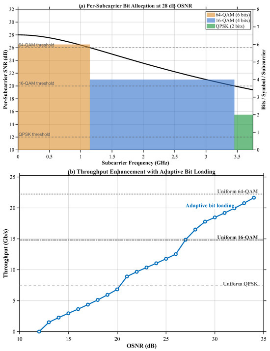
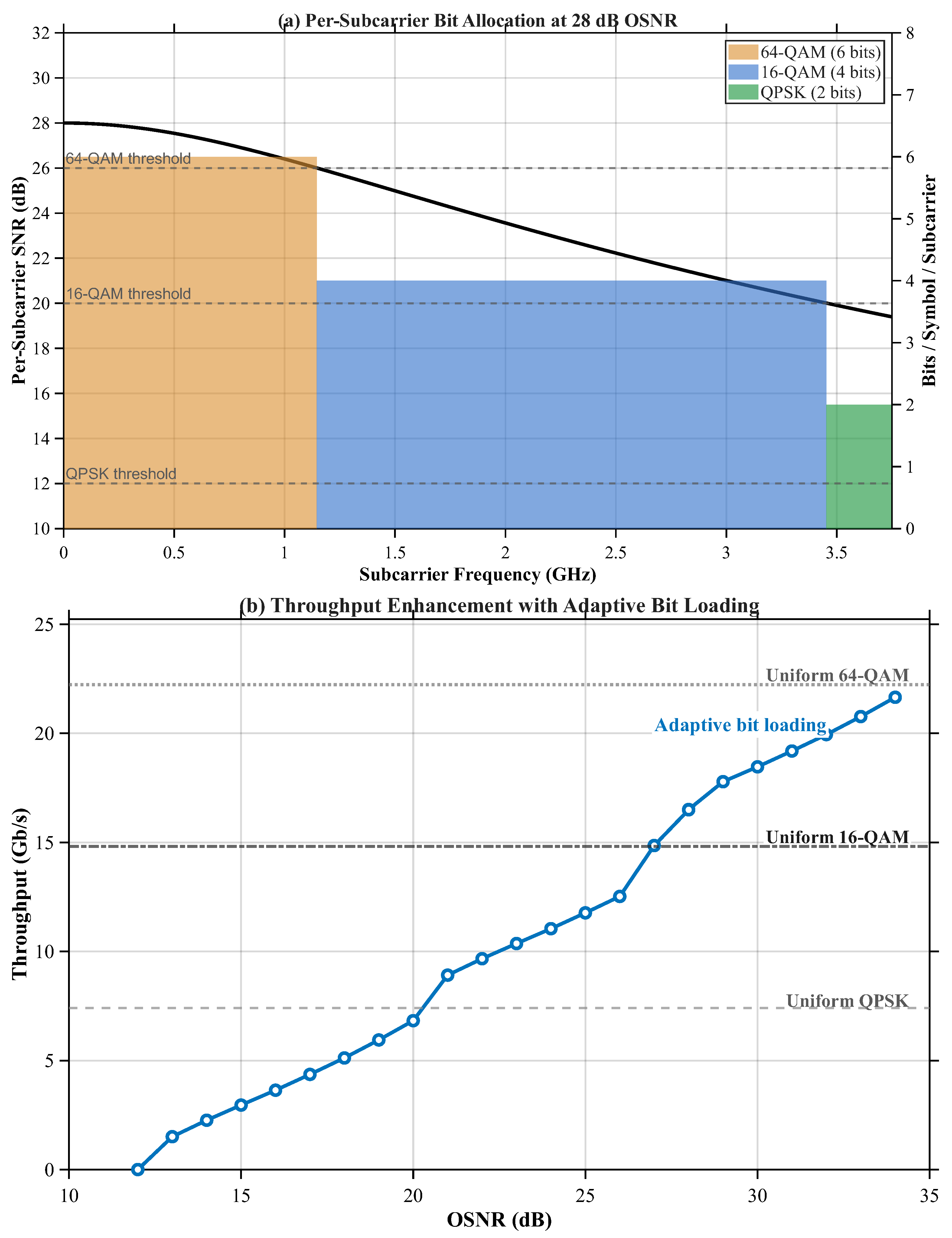
Figure 10a shows the per-subcarrier bit allocation for the full 511-subcarrier OFDM system at dB. The frequency-dependent SNR roll-off caused by the limited DML bandwidth is shown by the black curve. The SNR decreases from approximately 28 dB at the lowest-frequency subcarriers to about 19.4 dB at the highest active subcarrier frequency, approximately 3.75 GHz. Based on the adopted SNR thresholds, the adaptive algorithm assigns 64-QAM (6 bits/symbol) to the 156 lowest-frequency subcarriers where the SNR exceeds 26 dB, 16-QAM (4 bits/symbol) to 315 mid-frequency subcarriers, and QPSK (2 bits/symbol) to the remaining 40 high-frequency subcarriers near the band edge. Therefore, all 511 data subcarriers remain active at this OSNR, while their modulation orders are adjusted according to the available subcarrier SNR.
Figure 10.
Adaptive bit-loading analysis for the full 511-subcarrier OFDM system: (a) per-subcarrier SNR and bit allocation at 28 dB OSNR, showing the frequency-dependent transition from 64-QAM to 16-QAM and then QPSK toward the high-frequency band edge; (b) aggregate throughput comparison between adaptive bit-loading and the uniform QPSK, 16-QAM, and 64-QAM reference limits.
Figure 10b compares the aggregate throughput obtained using adaptive bit-loading with the fixed-throughput reference limits of uniform QPSK, uniform 16-QAM, and uniform 64-QAM over the considered OSNR range. Three operating regimes can be identified:
- Low OSNR (<20 dB): Only the lower-frequency subcarriers have sufficient SNR to support reliable transmission. Adaptive loading therefore assigns low-order modulation or disables weak subcarriers, resulting in a gradual throughput increase with OSNR.
- Mid OSNR (20–27 dB): More subcarriers exceed the QPSK and 16-QAM thresholds, so the adaptive throughput increases rapidly as a larger portion of the OFDM band becomes usable.
- High OSNR (>27 dB): The adaptive scheme exceeds the uniform 16-QAM throughput by promoting the strongest low-frequency subcarriers to 64-QAM while maintaining 16-QAM or QPSK on the weaker high-frequency subcarriers. At 28 dB OSNR, the adaptive throughput is approximately 16.5 Gb/s, compared with 14.82 Gb/s for uniform 16-QAM. At higher OSNR, the throughput approaches the uniform 64-QAM limit of approximately 22.23 Gb/s, and it reaches this limit once all subcarriers exceed the 64-QAM SNR threshold.
4. Conclusions
This work evaluated a low-complexity DM-DD-OFDM-VL-OWC link using a 520 nm directly modulated laser and 16-QAM DCO-OFDM over 500 m. The simulated system provides approximately 15 Gb/s gross and 14.82 Gb/s payload rates without external optical modulators or amplifiers. Under static line-of-sight conditions, the BER falls below at approximately 17 dB OSNR and remains below the adopted threshold for beam divergence up to approximately 9 mrad. The received-power results agree with the analytical link-budget values within 0.2–0.3 dB, confirming the internal consistency of the deterministic propagation implementation.
With Gamma–Gamma turbulence and a 5 cm receiver aperture, the BER remains below at 20 dB OSNR up to . The per-axis angular-jitter standard deviation corresponding to 1% pointing-induced outage is approximately 0.425, 0.515, and 0.564 mrad for 5, 10, and 15 cm apertures, respectively. Larger apertures therefore improve the power margin and alignment tolerance, although active tracking may still be required.
The adverse-weather analysis indicates that the clear-air margin is exhausted at approximately , corresponding to , or near 107 mm/h rain rate under the conservative uniform-path approximation. Within the selected cases, low-visibility haze/fog is more restrictive than the evaluated rain rates. For the 1.5 GHz bandwidth-limited DML case, adaptive bit loading reaches approximately 16.5 Gb/s at 28 dB OSNR, compared with 14.82 Gb/s for uniform 16-QAM.
Overall, the results support the proposed architecture as a potential low-complexity medium-range optical wireless solution. Experimental validation is required to confirm the predicted performance under practical outdoor operating conditions. Future work should combine short-range device calibration with outdoor measurements under recorded weather and pointing conditions, stronger FEC, spatial diversity, and practical alignment control.
Author Contributions
Conceptualization, M.A. and F.E.-N.; methodology, M.A.; software, M.A.; validation, M.A. and F.E.-N.; formal analysis, M.A.; investigation, M.A.; resources, M.A.; data curation, M.A.; writing—original draft preparation, M.A.; writing—review and editing, T.S. and F.E.-N.; visualization, M.A.; supervision, F.E.-N.; project administration, M.A. All authors have read and agreed to the published version of the manuscript.
Funding
This research received no external funding.
Institutional Review Board Statement
Not applicable.
Informed Consent Statement
Not applicable.
Data Availability Statement
The data supporting the findings of this study are available from the corresponding author upon reasonable request.
Acknowledgments
This publication was supported by the Scientific Research Projects Coordination Unit of Istanbul Yeni Yuzyil University.
Conflicts of Interest
The authors declare no conflicts of interest.
References
- Deepa, T.; Suseela, V.; Mani, V.V. Performance analysis of novel precoding matrix techniques for optical OFDM-based visible light communication systems. Opt. Laser Technol. 2022, 154, 108293. [Google Scholar] [CrossRef] [Scilit]
- Béchadergue, B.; Shen, W.-H.; Tsai, H.-M. Comparison of OFDM and OOK modulations for vehicle-to-vehicle visible light communication in real-world driving scenarios. Ad. Hoc. Netw. 2019, 94, 101944. [Google Scholar] [CrossRef] [Scilit]
- Najafi Chabok, S.; Baghersalimi, G.; Goorani, H. Performance optimization of hybrid VL-OWC-PLC systems using OFDM-QAM modulation for high-speed indoor communications. Results Opt. 2026, 22, 100946. [Google Scholar] [CrossRef] [Scilit]
- Kharbouche, A.; Madini, Z.; Zouine, Y.; El-Haryqy, N. Signal demodulation with deep learning methods for visible light communication. In Proceedings of the 2023 9th International Conference on Optimization and Applications (ICOA); IEEE: New York, NY, USA, 2023; pp. 1–5. [Google Scholar] [CrossRef] [Scilit]
- Kharbouche, A.; Madini, Z.; Zouine, Y. Analysis of realistic DS-OCDMA/VLC for V2X communication using OptiSystem. In Proceedings of the 2021 7th International Conference on Optimization and Applications (ICOA); IEEE: New York, NY, USA, 2021; pp. 1–5. [Google Scholar] [CrossRef] [Scilit]
- Chi, Y.-C.; Hsieh, D.-H.; Tsai, C.-T.; Chen, H.-Y.; Kuo, H.-C.; Lin, G.-R. 450-nm GaN laser diode enables high-speed visible light communication with 9-Gbps QAM-OFDM. Opt. Express 2015, 23, 13051–13059. [Google Scholar] [CrossRef] [Scilit] [PubMed]
- Lee, C.; Zhang, C.; Cantore, M.; Farrell, R.M.; Oh, S.H.; Margalith, T.; Speck, J.S.; Nakamura, S.; Bowers, J.E.; DenBaars, S.P. 4 Gbps direct modulation of 450 nm GaN laser for high-speed visible light communication. Opt. Express 2015, 23, 16232–16237. [Google Scholar] [CrossRef] [Scilit] [PubMed]
- Watson, S.; Tan, M.; Najda, S.P.; Perlin, P.; Leszczynski, M.; Targowski, G.; Grzanka, S.; Kelly, A.E. Visible light communications using a directly modulated 422 nm GaN laser diode. Opt. Lett. 2013, 38, 3792–3794. [Google Scholar] [CrossRef] [Scilit] [PubMed]
- Al Hasnawi, R.; Marghescu, I. A survey of vehicular VL-OWC methodologies. Sensors 2024, 24, 598. [Google Scholar] [CrossRef] [Scilit] [PubMed]
- Aghaei, F.; Eldeeb, H.B.; Bariah, L.; Muhaidat, S.; Uysal, M. Comparative characterization of indoor VL-OWC and MMW communications via ray tracing simulations. IEEE Access 2023, 11, 90345–90357. [Google Scholar] [CrossRef] [Scilit]
- Kharbouche, A.; Madini, Z.; Zouine, Y. Performance improvements of a VL-OWC system, in a V2X context, using a different multiplexing technique. TELKOMNIKA Telecommun. Comput. Electron. Control 2023, 21, 725–735. [Google Scholar] [CrossRef] [Scilit]
- Liu, C.B.; Sadeghi, B.; Knightly, E.W. Enabling vehicular visible light communication (V2LC) networks. In Proceedings of the Eighth ACM International Workshop on Vehicular Inter-Networking (VANET ’11); Association for Computing Machinery: New York, NY, USA, 2011; pp. 41–50. [Google Scholar]
- Matheus, L.E.M.; Vieira, A.B.; Vieira, L.F.M.; Vieira, M.A.M.; Gnawali, O. Visible light communication: Concepts, applications and challenges. IEEE Commun. Surv. Tutor. 2019, 21, 3204–3237. [Google Scholar] [CrossRef] [Scilit]
- Han, X.; Wang, W.; Li, P.; Li, G.; Nie, W.; Xie, Z.; Jia, S.; Chang, C.; Liao, P.; Xie, X. Demonstration of anti-diffracting optical pin-like beam enabled 5Gbit/s OFDM underwater wireless optical communication system. Opt. Commun. 2025, 579, 131582. [Google Scholar] [CrossRef] [Scilit]
- Al-Hamiri, M.G.; Abd, H.J. Enhancing the performance of LiFi communication with OSTBC, QAM, and OFDM: High-capacity, low-complexity transceiver design. Results Opt. 2024, 16, 100675. [Google Scholar] [CrossRef] [Scilit]
- El-Nahal, F.I.; Abualoff, N.M. Coherent optical communication systems based on orthogonal frequency division multiplexing. Optoelectron. Lett. 2020, 16, 303–305. [Google Scholar] [CrossRef] [Scilit]
- Camporez, H.; Costa, W.; Pontes, M.; Segatto, M.; Rocha, H.; Silva, J.; Hinrichs, M.; Paraskevopoulos, A.; Jungnickel, V.; Freund, R. Increasing the reach of visible light communication links through constant-envelope OFDM signals. Opt. Commun. 2023, 530, 129179. [Google Scholar] [CrossRef] [Scilit]
- Wen, H.; Chen, H.; Chen, Q.; Luo, K.; Chen, M.; Liu, F. Performance enhanced dual-mode index modulation OFDM with OCT precoding in VL-OWC systems. Opt. Commun. 2023, 530, 129191. [Google Scholar] [CrossRef] [Scilit]
- Mallaiah, R.; Miriyala, G.; Mani, V.V. A low-complex OFDM based DCO-OTFS modulation for VL-OWC systems. Phys. Commun. 2024, 66, 102471. [Google Scholar] [CrossRef] [Scilit]
- Zenhom, Y.A.; Hamad, E.K.I.; Elkarim, M.A.; Elnabawy, M.M. Alleviating high PAPR and noise issues for optimized performance in ACO-OFDM-based VL-OWC systems. Opt. Laser Technol. 2025, 188, 112950. [Google Scholar] [CrossRef] [Scilit]
- Ahmad, F.; Jawaid, M. A review of modulation schemes for visible light communication. IJCSNS Int. J. Comput. Sci. Netw. Secur. 2018, 18, 117–125. [Google Scholar]
- Aliaberi, A.; Sofotasios, P.C.; Muhaidat, S. Modulation schemes for visible light communications. In Proceedings of the 2019 International Conference on Advanced Communication Technologies and Networking (CommNet); IEEE: New York, NY, USA, 2019; pp. 1–10. [Google Scholar]
- Vappangi, S.; Mani, V.V.; Sellathurai, M. Visible Light Communication: A Comprehensive Theory and Applications with MATLAB; CRC Press: Boca Raton, FL, USA, 2021. [Google Scholar]
- Othman, N.; Beson, M.R.C.; Aljunid, S.A.; Endut, R. A review: Outdoor visible light communication on modulation and receiver denoising scheme. AIP Conf. Proc. 2024, 2898, 030038. [Google Scholar] [CrossRef] [Scilit]
- Zhang, X.; Babar, Z.; Petropoulos, P.; Haas, H.; Hanzo, L. The evolution of optical OFDM. IEEE Commun. Surv. Tutor. 2021, 23, 1430–1457. [Google Scholar] [CrossRef] [Scilit]
- Tsonev, D.; Videv, S.; Haas, H. Unlocking spectral efficiency in intensity modulation and direct detection systems. IEEE J. Sel. Areas Commun. 2015, 33, 1758–1770. [Google Scholar] [CrossRef] [Scilit]
- Jativa, P.P.; Azurdia-Meza, C.A.; Canizares, M.R.; Zabala-Blanco, D.; Montejo-Sanchez, S. Performance analysis of OFDM-based VL-OWC schemes in NLOS channels. In Proceedings of the 2020 South American Colloquium on Visible Light Communications (SACVL-OWC); IEEE: New York, NY, USA, 2020. [Google Scholar]
- Sun, Y.; Yang, F.; Gao, J. Comparison of hybrid optical modulation schemes for visible light communication. IEEE Photonics J. 2017, 9, 1–13. [Google Scholar] [CrossRef] [Scilit]
- Singh, R.; O’Farrell, T.; David, J.P. Performance comparison of multi-carrier modulation techniques for intensity-modulated optical wireless communication systems. IEEE Trans. Commun. 2018, 66, 4949–4962. [Google Scholar]
- Alhalabi, M.; El-Nahal, F.I.; Taşpinar, N. Comparison of different modulation techniques for optical OFDM intensity modulation and direct detection IM/DD system. In Proceedings of the 2019 IEEE 7th Palestinian International Conference on Electrical and Computer Engineering (PICECE); IEEE: New York, NY, USA, 2019; pp. 1–4. [Google Scholar] [CrossRef] [Scilit]
- Alhalabi, M.; Taşpınar, N.; Wadi, M.; Salemdeeb, M. Performance analysis of a low-cost directly modulated OFDM-based optical wireless communication systems. Wirel. Pers. Commun. 2026, 146, 1415–1441. [Google Scholar] [CrossRef] [Scilit]
- Rehman, S.U.; Ullah, S.; Chong, P.H.J.; Yongchareon, S.; Komosny, D. Visible light communication: A system perspective—Overview and challenges. Sensors 2019, 19, 1153. [Google Scholar] [CrossRef] [Scilit] [PubMed]
- Lian, J.; Vatansever, Z.; Noshad, M.; Brandt-Pearce, M. Indoor visible light communications, networking, and applications. J. Phys. Photonics 2019, 1, 012001. [Google Scholar] [CrossRef] [Scilit]
- Zhuang, Y.; Hua, L.; Qi, L.; Yang, J.; Cao, P.; Cao, Y.; Wu, Y.; Thompson, J.; Haas, H. A survey of positioning systems using visible LED lights. Sensors 2020, 20, 1382. [Google Scholar] [PubMed]
- Sliti, M.; Mrabet, M.; Garai, M.; Ammar, L.B. A survey on machine learning algorithm applications in visible light communication systems. Opt. Quantum Electron. 2024, 56, 1351. [Google Scholar] [CrossRef] [Scilit]
- Arafa, N.A.; El-Att, S.M.A.; Eldeeb, H.B.; Arafa, M.S. Deep learning-based automatic modulation format identification for I2V visible light communication. In Proceedings of the 2024 41st National Radio Science Conference (NRSC); IEEE: New York, NY, USA, 2024; Volume 1, pp. 191–199. [Google Scholar]
- Eldeeb, H.B.; Qaraqe, M.; Muhaidat, S.; Ghrayeb, A. Reconfigurable intelligent surfaces-assisted I2V-visible light communication. In Proceedings of the 2024 IEEE International Mediterranean Conference on Communications and Networking (MeditCom); IEEE: New York, NY, USA, 2024; pp. 465–470. [Google Scholar]
- Farid, A.A.; Hranilovic, S. Outage capacity optimization for free-space optical links with pointing errors. J. Lightw. Technol. 2007, 25, 1702–1710. [Google Scholar] [CrossRef] [Scilit]
- Feng, Z.; Li, N.; Li, W.; He, P.; Luo, M.; Hu, Q.; Huang, L.; Jiang, Y. A simplified Volterra equalizer based on system characteristics for direct modulation laser (DML)-based intensity modulation and direct detection (IM/DD) transmission systems. Photonics 2023, 10, 1174. [Google Scholar] [CrossRef] [Scilit]
- Alhalabi, M.; Taşpınar, N.; El-Nahal, F. Bidirectional intensity modulated/direct detection optical OFDM WDM-PON system. Optoelectron. Lett. 2023, 19, 83–87. [Google Scholar] [CrossRef] [Scilit]
- Alhalabi, M.; Taşpınar, N.; Wadi, M. PAPR reduction using discrete forest optimization algorithm based on SLM technique in intensity modulated direct detection optical OFDM communication systems. Int. J. Commun. Syst. 2025, 38, e70126. [Google Scholar] [CrossRef] [Scilit]
- El-Nahal, F.; Xu, T.; AlQahtani, D.; Leeson, M. A bidirectional WDM-PON free space optical (FSO) system for fronthaul 5G C-RAN networks. IEEE Photonics J. 2023, 15, 7300208. [Google Scholar] [CrossRef] [Scilit]
- AlQahtani, D.; El-Nahal, F. Coherent WDM-PON and free space optical (FSO) system for front-haul in next-generation cellular networks. Optik 2025, 323, 172212. [Google Scholar] [CrossRef] [Scilit]
- Mohsin, M.J.; Murdas, I.A. Performance analysis of an outdoor Li-Fi system-based AO-OFDM architecture under different FSO turbulence and weather conditions. Optik 2023, 273, 170427. [Google Scholar] [CrossRef] [Scilit]
- Oria, A.C.O.; Becerra, J.A.; Madero-Ayora, M.J.; Lecuyer, V.B.; Crespo-Cadenas, C. Symbol constellation predistortion for DCO-OFDM visible light communications system linearization. Digit. Signal Process. 2025, 165, 105310. [Google Scholar] [CrossRef] [Scilit]
- Alhalabi, M.; Taşpınar, N.; Wadi, M.; El-Nahal, F. Performance enhancement of IM/DD optical OFDM through SLM-based PAPR reduction. Optoelectron. Lett. 2026, 22, 366–372. [Google Scholar] [CrossRef] [Scilit]
- Alhalabi, M.; Taşpınar, N.; Sönmezocak, T. A novel hybrid whale optimization algorithm-based SLM (HWOA-SLM) for PAPR reduction in optical IM/DD OFDM systems. Appl. Sci. 2026, 16, 2349. [Google Scholar] [CrossRef] [Scilit]
- Bloom, E.; Korevaar, E.; Schuster, J.; Willebrand, H. Understanding the performance of free-space optics. J. Opt. Netw. 2003, 2, 178–200. [Google Scholar] [CrossRef] [Scilit]
- Zhang, W.; Jin, Y.; Ren, H.; Liu, J.; Li, L. Full-space programmable metasurface for Bessel beam tailoring. Opt. Express 2022, 30, 15512–15524. [Google Scholar] [CrossRef] [Scilit] [PubMed]
- Borah, D.K.; Voelz, D.G. Pointing error effects on free-space optical communication links in the presence of atmospheric turbulence. J. Lightw. Technol. 2009, 27, 3965–3973. [Google Scholar] [CrossRef] [Scilit]
- International Telecommunication Union. Prediction Methods Required for the Design of Terrestrial Free-Space Optical Links; Recommendation ITU-R P.1814-1; ITU: Geneva, Switzerland, 2025. [Google Scholar]
- Qiu, P.; Cui, G.; Qian, Z.; Zhu, S.; Shan, X.; Zhao, Z.; Zhou, X.; Cui, X.; Tian, P. 4.0 Gbps visible light communication in a foggy environment based on a blue laser diode. Opt. Express 2021, 29, 14163–14173. [Google Scholar] [CrossRef] [Scilit] [PubMed]
- Xiao, Y.; Ai, J.; Chen, X.; Cui, X.; Tian, P. 30 Gbps visible light communication in rainy environments based on laser diodes. Chin. Opt. Lett. 2025, 23, 060604. [Google Scholar] [CrossRef] [Scilit]

Disclaimer/Publisher’s Note: The statements, opinions and data contained in all publications are solely those of the individual author(s) and contributor(s) and not of MDPI and/or the editor(s). MDPI and/or the editor(s) disclaim responsibility for any injury to people or property resulting from any ideas, methods, instructions or products referred to in the content. |
© 2026 by the authors. Licensee MDPI, Basel, Switzerland. This article is an open access article distributed under the terms and conditions of the Creative Commons Attribution (CC BY) license.