


Featured Application
This study provides a quantitative basis for understanding projection-dependent discrepancies in 2D dental images used in CAD/CAM workflows. The findings support the development of AI-assisted image adjustment approaches to improve consistency when integrating 2D photographs with 3D intraoral scan data in digital prosthetic design. Beyond conventional CAD/CAM workflows, the present findings may inform the development of geometry-aware AI systems capable of correcting projection-induced distortion in dental photographs before integration into virtual patient environments, smile design platforms, and automated prosthetic planning systems.
Abstract
This study quantified projection-dependent geometric distortion induced by vertical camera angulation in two-dimensional (2D) dental image acquisition and evaluated its implications for integration with three-dimensional (3D) CAD/CAM and artificial intelligence (AI)-driven workflows. To our knowledge, this study is among the first to use quantitative methods to characterize projection-induced distortion across the dental arch as a function of vertical camera angulation. Fourteen fully dentate casts were photographed at nine standardized vertical angulations using a controlled acquisition setup based on the standardized occlusal plane angle (SOPA). Tooth surface areas were measured through digital tracing and analyzed with a mixed-effects model (α = 0.05). Significant associations were identified between vertical camera angulation and measured tooth surface area for all teeth except canines (p < 0.05 for all except canines). Anterior teeth demonstrated increased apparent surface area at superior camera angulations, whereas posterior teeth were more prominently represented at inferior angulations. Central incisors, lateral incisors, and first premolars exhibited maximal visibility above the occlusal plane, while second premolars and molars were more optimally visualized below it. These findings indicate that vertical camera angulation induces non-uniform, region-specific geometric distortion across the dental arch. From a computational perspective, these distortions represent a systematic source of variability in 2D photographic datasets used in CAD/CAM workflows, virtual smile design, and AI-assisted image analysis. Because modern machine learning systems depend on geometrically consistent input data, uncorrected projection-induced distortion may reduce the reliability and generalizability of downstream algorithmic outputs. Accordingly, the present findings establish a quantitative basis for recognizing projection-induced variability in 2D dental photographs and support future development of geometry-aware calibration strategies for 2D-3D digital integration. AI-assisted correction represents a future translational direction contingent upon explicit alignment between acquisition geometry, image formation, and computational modeling.
1. Introduction
1.1. Digital Dentistry and the Rise of Integrated Virtual Workflows
Digital dentistry has transitioned from analog documentation toward data-driven reconstruction of the patient through integrated CAD/CAM and virtual patient ecosystems. Contemporary workflows routinely merge two-dimensional (2D) photographic data with three-dimensional (3D) intraoral scans (IOS) to generate diagnostic wax-ups, prosthetic simulations, and treatment planning models. These multimodal datasets form the basis of increasingly sophisticated virtual patient representations, in which anatomical, functional, and esthetic parameters are co-registered within an integrated digital environment [1,2,3,4]. Despite the emergence of 3D facial scanning technologies, their clinical adoption remains limited due to cost, accessibility, and workflow complexity [4,5]. Consequently, 2D facial and intraoral photographs remain the most widely utilized and practical modality for esthetic and prosthetic planning [6,7]. Within this evolving landscape, modern reconstructive dentistry increasingly relies on integrated digital systems that require alignment across multiple imaging modalities, computational workflows, and prosthetic design processes [1,2,3,4,8,9]. Integration across imaging modalities has become routine, yet remains dependent on the consistency of input data [1,3,4,10,11,12,13,14].
1.2. Projection Geometry as an Underrecognized Source of Distortion
However, integrating 2D images into 3D computational environments introduces a fundamental yet underrecognized limitation: projection-induced geometric distortion. Unlike true 3D metric data, 2D images are perspective projections of three-dimensional structures and are inherently sensitive to camera positioning parameters. Among these, vertical camera angulation plays a critical role in modulating perceived tooth dimensions, spatial relationships, and occlusal curvature. This dependency reflects well-established principles in computer vision, where image formation is governed by intrinsic and extrinsic camera parameters that influence scaling, foreshortening, and spatial transformation [15,16].
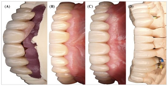
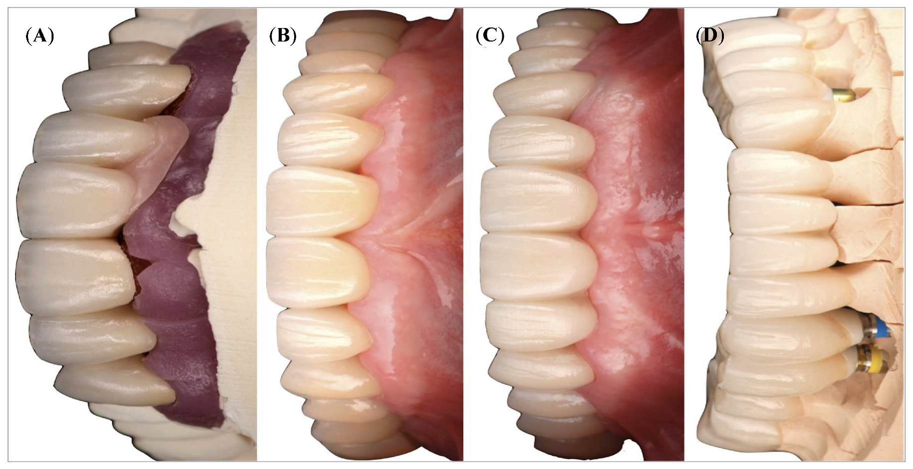
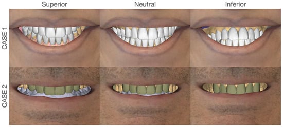
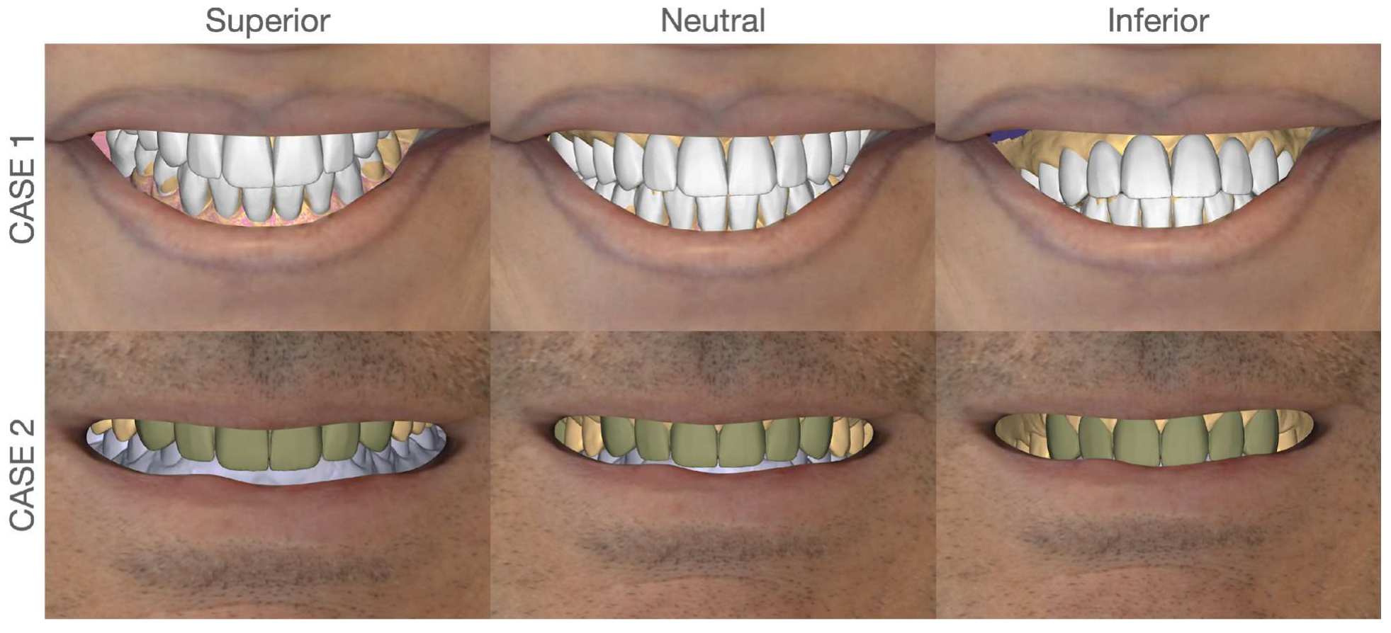
In clinical practice, frontal esthetic images are commonly assumed to approximate a “neutral” representation when the camera is positioned perpendicular to the facial plane [6]. Yet even subtle deviations in vertical angulation can induce nonlinear scaling distortions (Figure 1), altering the apparent surface area and proportional relationships of teeth. Quantitative evidence suggests that variations in vertical camera angulation may introduce non-linear and region-specific distortion patterns, with anterior and posterior teeth exhibiting differing sensitivities to projection geometry [15,16]. When such distorted 2D data are integrated into CAD-based workflows, discrepancies may propagate into prosthetic design [8,9,17,18] (Figure 2).
Figure 1.
Frontal views of maxilla (A–C) and mandible (D) taken at various vertical camera angle positions and their visual variations.
Figure 2.
Angle-dependent geometric discrepancy in 2D-to-3D integration. Simulated interpretations of a single 2D esthetic image within a 3D CAD environment under varying angular assumptions (superior, neutral, and inferior). Although the source image remains identical, differences in the assumed projection angle lead to changes in tooth proportions and spatial distribution. This demonstrates an inherent potential for discrepancy when 2D photographic data are merged with 3D intraoral scan datasets for CAD-based diagnostic and prosthetic workflows.
1.3. Computational Perspective: Data Acquisition Bias in Digital Workflows
From a computational perspective, this phenomenon represents a systematic bias in data acquisition, analogous to calibration errors in imaging systems [15,16]. While digital dentistry increasingly relies on artificial intelligence (AI) and machine learning for automated design and decision support, these systems remain fundamentally dependent on the consistency of input data [1,10,11]. Recent studies have demonstrated the application of image processing and deep learning techniques for tooth detection, classification, and diagnostic analysis, highlighting the growing role of image-based data in dental workflows [19,20,21]. Uncorrected geometric distortions in 2D images introduce variability into downstream workflows.
Recent advances in single-image 3D reconstruction using diffusion-based and deep learning models further demonstrate the potential to recover high-fidelity three-dimensional structure from two-dimensional inputs, including domain-adaptive diffusion approaches capable of maintaining reconstruction fidelity under heterogeneous acquisition conditions [22]. Unlike calibrated imaging systems in computer vision, routine dental photography lacks formalized geometric correction pipelines, thereby introducing unquantified variability into downstream digital workflows [15,16].
1.4. Artificial Intelligence and the Problem of Geometric Inconsistency
In AI-driven dental systems, including automated smile design, tooth segmentation, and prosthetic planning algorithms, input data are implicitly assumed to be geometrically consistent. However, such models are highly sensitive to distributional shifts in input geometry, a phenomenon well-documented in machine learning as a source of reduced model generalizability and performance degradation. In this regard, vertical camera angulation serves as a hidden confounding variable that systematically alters feature representation without explicit annotation [10,11].
This introduces a critical translational challenge: the absence of standardized geometric normalization protocols for 2D dental images prior to integration into computational pipelines [15,16]. Without such correction, projection-induced distortion may be embedded within learned representations as anatomical truth, leading to propagated inaccuracies in both diagnostic interpretation and prosthetic design outputs [10,11]. Furthermore, recent developments in AI-assisted implant planning and automated virtual workflows highlight that even minor inconsistencies in input geometry can influence treatment simulations, reinforcing the need for geometry-aware preprocessing strategies [12,13]. Recent studies further demonstrate the sensitivity of image-based dental AI systems to variations in acquisition conditions, including geometry and imaging protocols [19,20,21].
1.5. Study Rationale and Conceptualization
Accordingly, the present investigation positions vertical camera angulation as a computational variable, bridging dental photography with principles of computer vision, geometric calibration, and data-driven model reliability.
To date, the quantitative relationship between vertical camera angulation and its geometric impact on dental structures has not been rigorously characterized. Therefore, the present study introduces a standardized geometric reference—the standardized occlusal plane angle (SOPA)—and systematically evaluates how deviations from this reference influence the perceived surface area of individual teeth.
Because a single 2D image represents a projection rather than a fixed geometric condition, interpretation varies with viewing angle [15,16]. Beyond establishing evidence-based photographic guidelines, this work aims to provide a computational foundation for future calibration strategies, including AI-assisted correction of 2D image distortion prior to integration into 3D CAD/CAM environments [1,10,11]. The null hypothesis was that vertical camera angulation would not significantly affect the measured tooth surface area.
This study provides a quantitative, tooth-specific characterization of projection-induced distortion and introduces the standardized occlusal plane angle (SOPA) as a reproducible geometric reference for geometry-aware integration.
2. Materials and Methods
2.1. Study Design and Image Acquisition
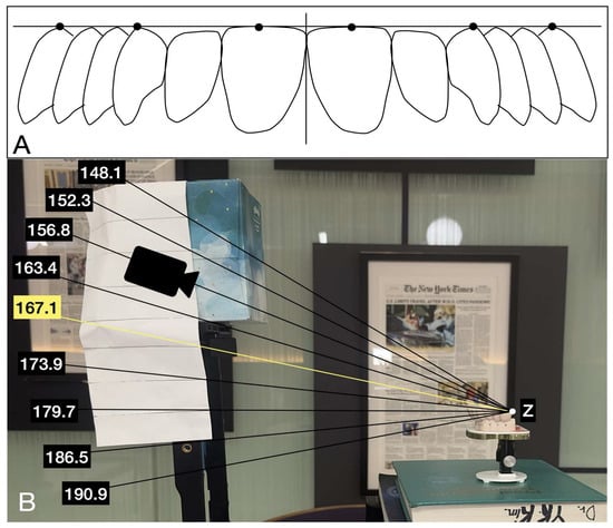
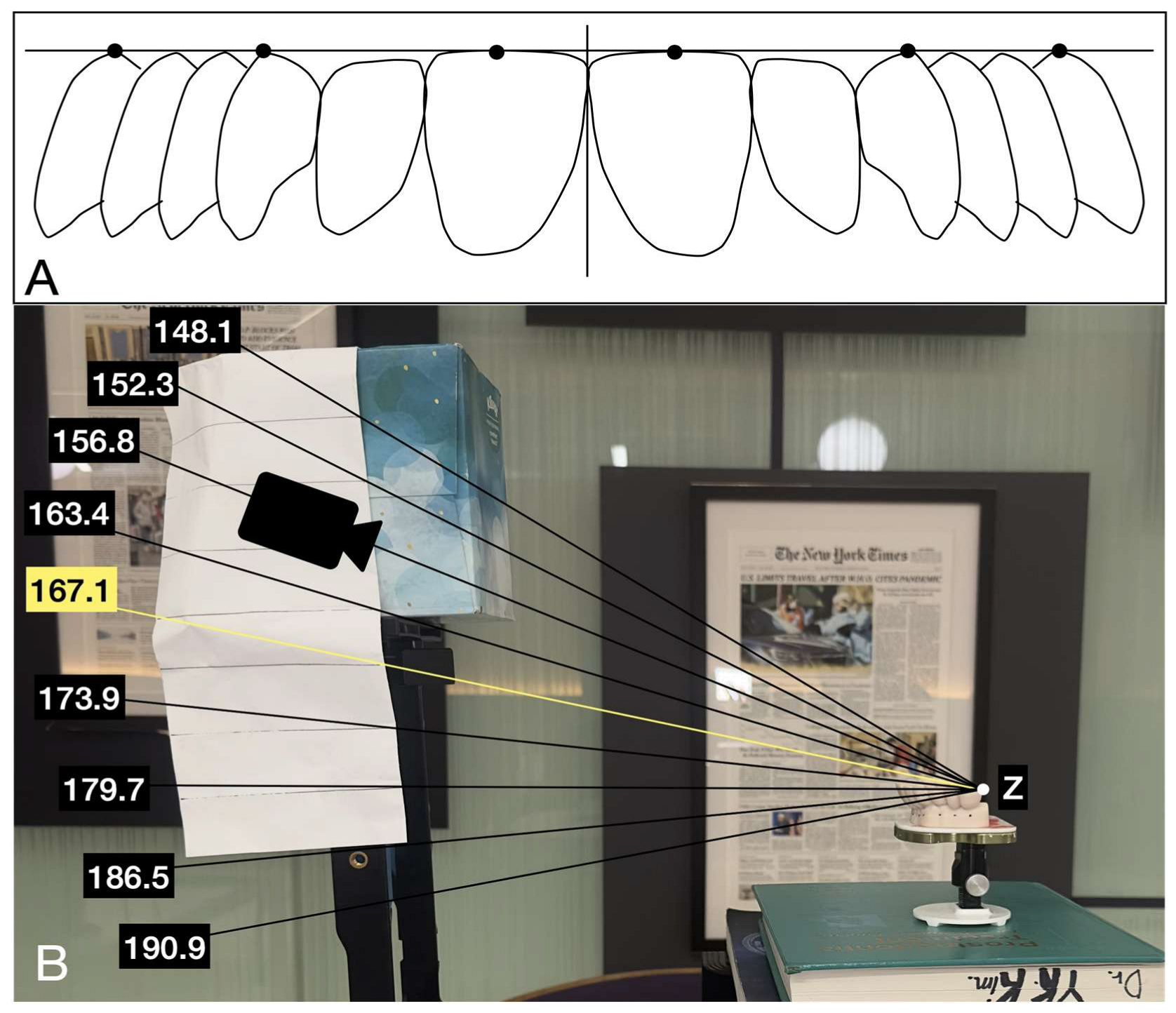
The standardized occlusal plane angle (SOPA) was defined as the angular relationship between the occlusal plane and the camera sensor that produced the most linear and geometrically consistent frontal projection of the dental arch (Figure 3). The occlusal plane was established using clinically identifiable anatomical landmarks, including the incisal edge of the central incisor and the cusp tips of posterior teeth, forming a distributed and stable reference plane for alignment.
Figure 3.
(A) Definition of the standardized occlusal plane angle (SOPA) and its geometric reference framework. (B) Experimental setup illustrating the nine vertical camera angulations relative to the occlusal plane. Angles below the SOPA reference represent inferior camera positioning (infra-occlusal), while angles above represent superior camera positioning (supra-occlusal). Z represents the terminal point of the SOPA plane.
To ensure reproducibility, SOPA was operationally identified as the camera orientation at which these anterior and posterior occlusal reference points demonstrated the smallest apparent vertical deviation relative to a fixed horizontal baseline. Linearity was defined as the configuration in which incisal edges and posterior cusp tips formed the most collinear horizontal relationship with minimal apparent curvature in the frontal projection. This assessment was performed consistently across all samples using the same visual and geometric criteria, allowing standardized identification of the SOPA reference orientation.
Image formation was conceptualized using a simplified perspective projection model, in which three-dimensional dental cast landmarks are projected onto a two-dimensional image plane. In this model, the apparent position and area of a tooth in the image depend on both the object geometry and the camera orientation. Because camera distance, focal setting, sensor orientation, and acquisition environment were held constant, vertical camera angulation was isolated as the primary experimental variable affecting projected surface area.
SOPA was experimentally derived rather than mathematically optimized. Therefore, it should be interpreted as a controlled, clinically reproducible imaging reference rather than a fully automated geometric calibration algorithm. This distinction was intentional because the purpose of the present study was to quantify angle-dependent changes in projection under controlled photographic conditions, not to validate a computer-vision calibration system. Nevertheless, camera positioning and angular control were standardized to minimize acquisition variability and ensure reproducibility across all measurements.
Fourteen fully dentate diagnostic casts were photographed with an iPhone 13 Pro mounted on a vertical tripod. Each cast served as its own control and was evaluated across multiple vertical angulations, allowing for within-subject comparison of measurement variability. A fixed table provided a consistent horizontal reference (Figure 3A). Vertical angulations were defined relative to the occlusal plane, which served as the primary reference plane for all measurements. The angle was measured between the occlusal plane and the camera sensor plane in the sagittal direction. A value of approximately 167.1° corresponded to a near-perpendicular orientation of the camera relative to the occlusal plane (SOPA). Angles less than this reference (e.g., 148.1–163.4°) represented inferior camera positioning (camera positioned below the occlusal plane), whereas angles greater than this reference (e.g., 173.9–190.9°) represented superior camera positioning (camera positioned above the occlusal plane). The tested angulations (148.1°, 152.3°, 156.8°, 163.4°, 167.1°, 173.9°, 179.7°, 186.5°, and 190.9°) were selected to systematically sample both infra-occlusal and supra-occlusal imaging positions (Figure 3B). These nine angulations were not intended to represent default camera settings. Rather, they were experimentally selected positions designed to sample a controlled range below, near, and above the SOPA reference. The same camera position and object distance were maintained throughout the experiment, and angular changes were introduced by controlled vertical repositioning relative to the occlusal reference plane. Thus, the nine positions represent experimental angular sampling conditions rather than clinical camera presets.
2.2. Measurements
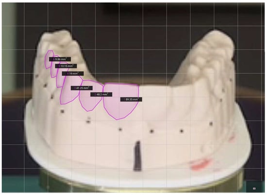
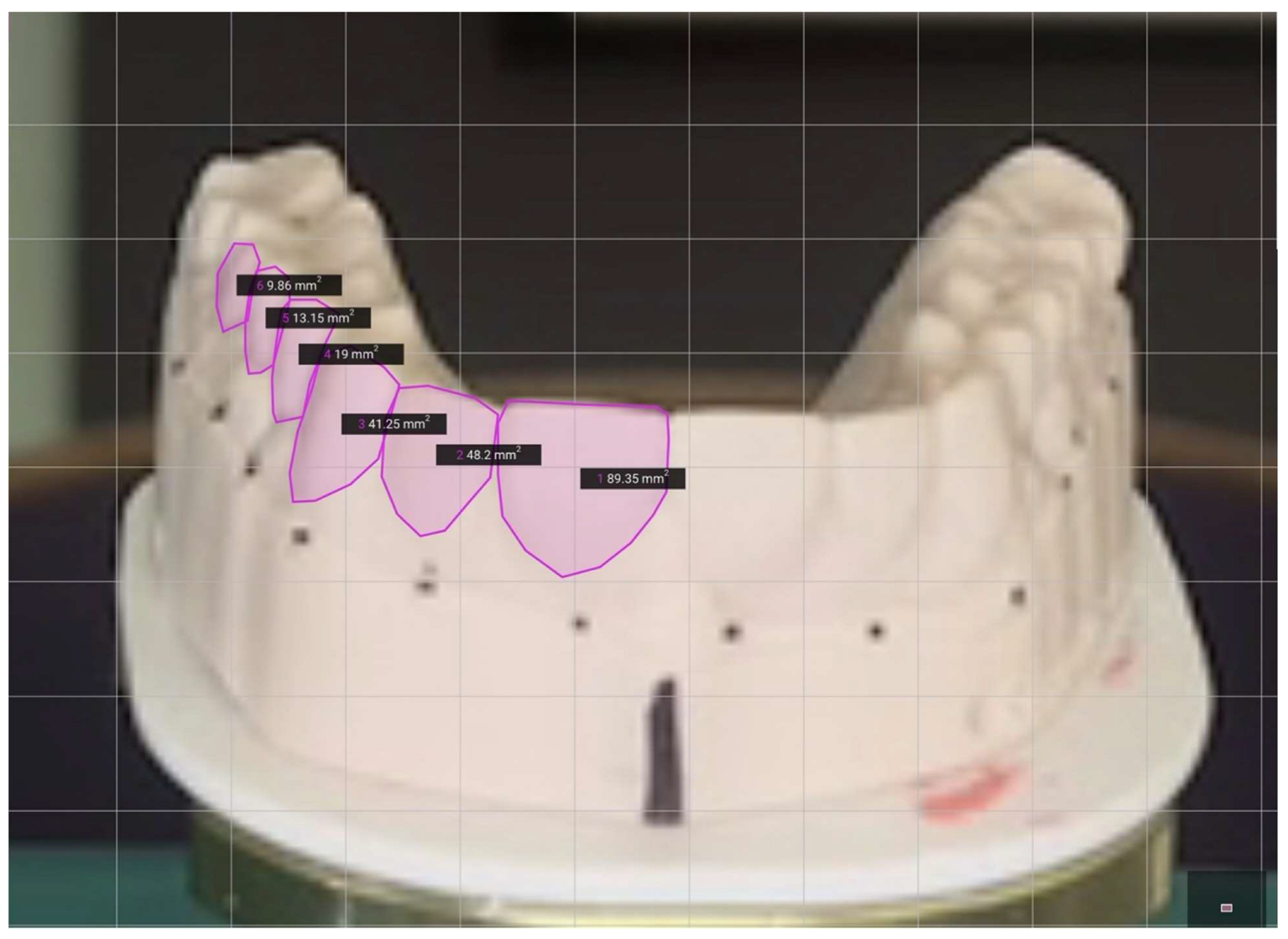
Tooth surface areas for the central incisor, lateral incisor, canine, first (PM1) and second premolars (PM2), and molar were then calculated using SketchAndCalc® (version 5.1.2) based on traced outlines (Figure 4). The vertical-axis values reported in the results represent projected tooth surface area, measured in square millimeters. These values do not indicate true anatomical tooth surface area; rather, they represent the apparent two-dimensional projected area obtained from each photograph under a specific vertical angulation. Scaling was standardized across all images using the fixed base as a reference. The same scaling reference was applied consistently across all images to minimize measurement variability unrelated to vertical angulation. Manual tracing was performed using standardized tooth-outline landmarks, and repeated image acquisition across angulations allowed each cast to serve as its own internal control. Area values were recorded in mm2 and analyzed using SAS (version 9.4). Measurements were obtained for each tooth type at every angulation, and mean values were calculated across all casts to assess trends in dimensional variation.
Figure 4.
Area calculations of different teeth performed using SketchAndCalc® (version 5.1.2; SketchAndCalc™, Palm Coast, FL, USA). Circumferences of the teeth are first traced out based on reference points for the area values generated by the software through the shoelace algorithm in squared millimeters.
2.3. Outcome Measures
The primary outcome measure was the projected two-dimensional surface area of each tooth group as represented in the frontal photograph. Tooth groups included the central incisor, lateral incisor, canine, first premolar, second premolar, and molar. Changes in projected area across vertical angulations were used to quantify projection-induced geometric distortion. Relative change from the SOPA reference angle was calculated to estimate the magnitude of distortion for each tooth type.
2.4. Image Acquisition Control
To ensure experimental reproducibility, all images were acquired under controlled lighting conditions using the same camera, focal length, sensor orientation, tripod system, and object distance. A fixed table and mounting configuration were used to maintain a constant horizontal reference. Vertical angulation was verified before image acquisition, and all casts were photographed using the same sequence of angular positions. Angular positioning was controlled using a digital inclinometer and verified before each acquisition. Repeated positioning confirmed consistency within a narrow tolerance range of approximately ±0.5°. These controls were intended to reduce variability from magnification, lighting, operator handling, and camera-to-object distance, thereby isolating vertical angulation as the principal experimental variable. All clinical photographs presented in this study were obtained in a private practice setting under full patient disclosure and informed consent. Written consent for clinical documentation, academic publication, and educational use of the images was obtained prior to inclusion in the present manuscript.
2.5. Statistical Analysis
Mixed-effects regression models were performed separately for each tooth type to evaluate the relationship between vertical camera angulation and projected tooth surface area. Vertical angulation was modeled as a fixed effect, and cast identity was included as a random intercept to account for repeated measurements within the same cast. This model structure was selected because each of the 14 casts was photographed repeatedly across nine angular positions, creating within-cast correlation that would not be adequately addressed by an independent-samples analysis.
Statistical significance was assessed using Type III tests of fixed effects. Regression coefficients (β), 95% confidence intervals, F-values, p-values, and partial eta squared effect sizes were calculated for each tooth type. Statistical significance was set at α = 0.05. The mixed-effects approach was used to evaluate whether projected tooth surface area varied systematically with vertical angulation, while accounting for inter-cast variability.
Descriptive statistics were also calculated for each tooth type at each angular position and reported as mean projected area ± standard deviation. These descriptive values were used to visualize angle-dependent trends and to identify the angulation associated with maximal projected visibility for each tooth group.
3. Results
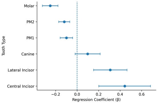
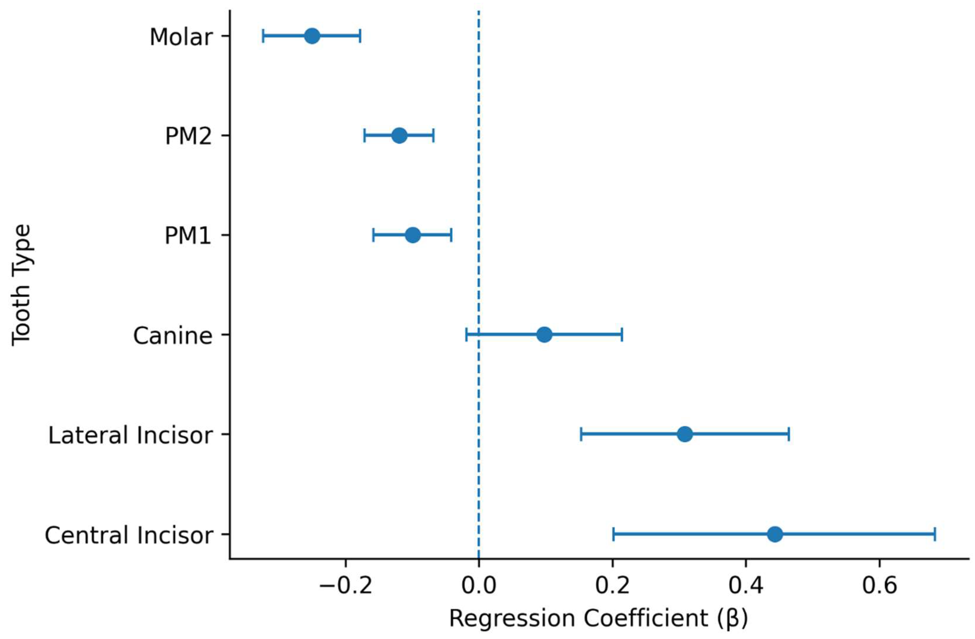
The effect of vertical camera angulation on projected tooth surface area was evaluated using mixed-effects regression models based on traced area measurements (Figure 4). The results are summarized in Table 1. The direction and magnitude of these associations are visually summarized in Figure 5. Representative visual changes across angulations are illustrated (Figure 1).
Table 1.
Mixed-effects model results evaluating the effect of vertical camera angulation on projected tooth surface area.
Figure 5.
Forest plot of mixed-effects regression coefficients for the effect of vertical camera angulation on projected tooth surface area. Points represent regression coefficients (β), and horizontal bars indicate 95% confidence intervals. The vertical dashed line represents the null value (β = 0). Positive coefficients indicate increasing projected surface area with increasing vertical angulation, whereas negative coefficients indicate decreasing projected surface area. The confidence interval for canines crosses zero, consistent with the absence of statistical significance.
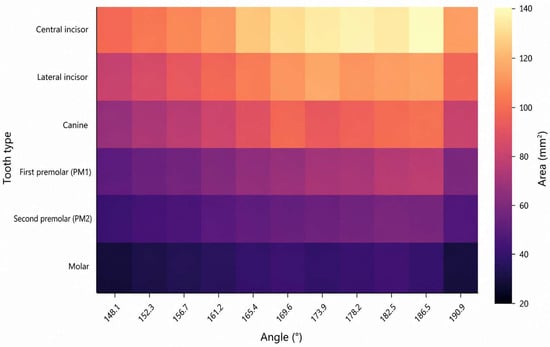
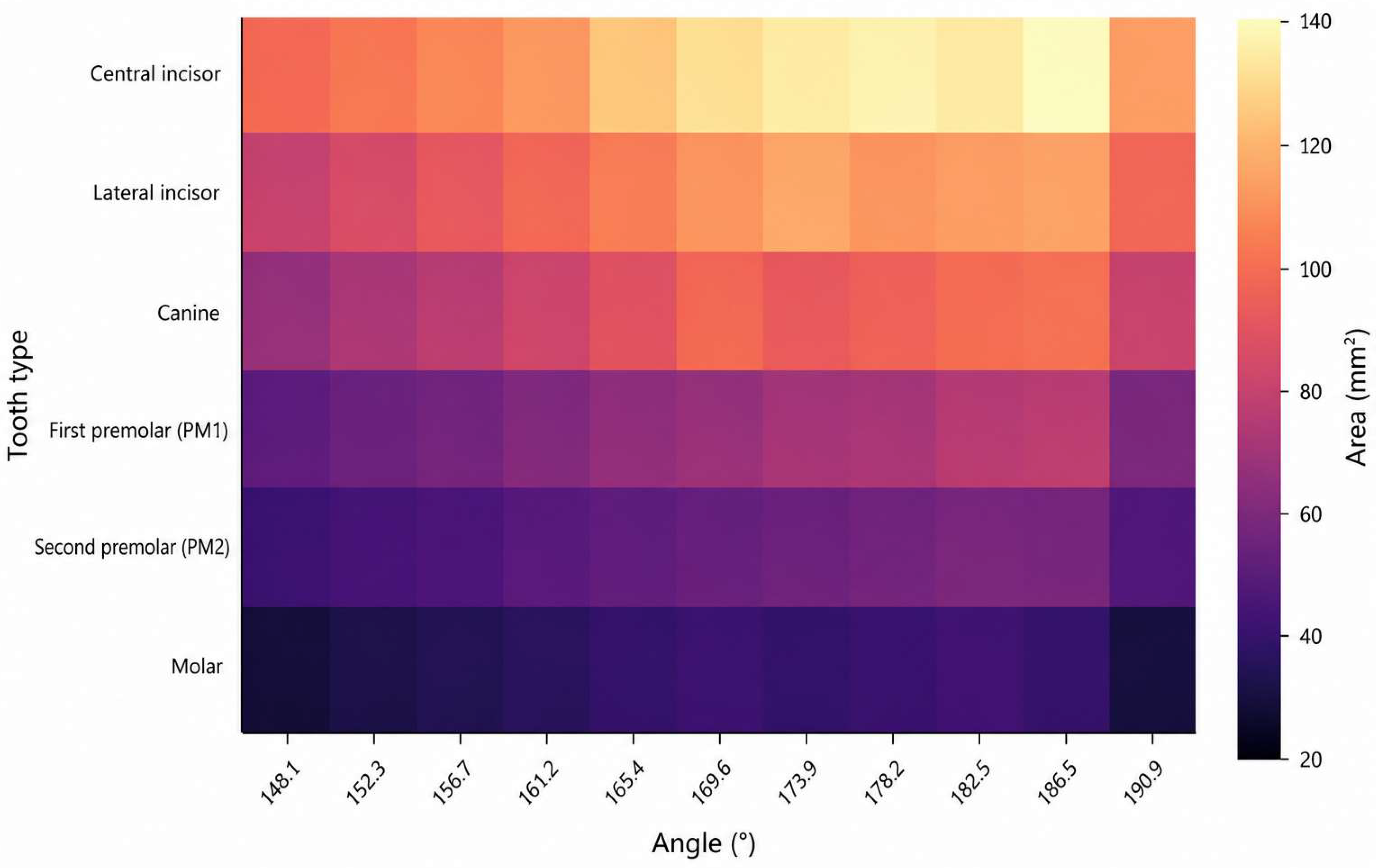
Descriptive statistics for projected tooth surface area across all angulations are presented in Table 2, illustrating non-linear and region-specific variation in projected tooth dimensions. To further characterize this spatially heterogeneous pattern, a heatmap representation is provided (Figure 6). A spatial inversion pattern is observed, with anterior intensity increasing at higher angulations and posterior intensity increasing at lower angulations.
Table 2.
Mean projected tooth surface area (mm2) ± standard deviation by tooth type and vertical camera angulation.
Figure 6.
Heatmap of projected tooth surface area across vertical camera angulations. Color intensity represents the mean projected surface area (mm2) derived from Table 2. The heatmap reveals non-linear, region-dependent variation across the dental arch, with anterior teeth exhibiting greater surface representation at higher angulations and posterior teeth demonstrating relatively greater visibility at lower angulations.
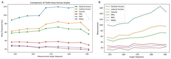
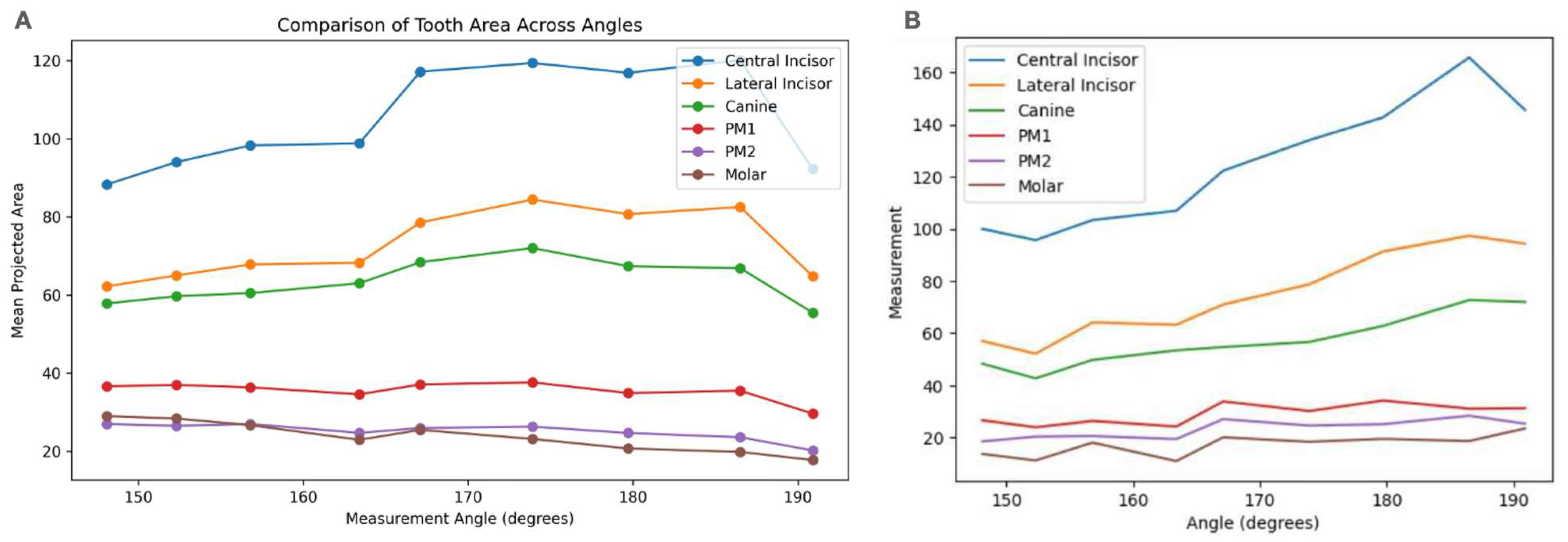
Mixed-effects regression analysis demonstrated a statistically significant association between vertical camera angulation and projected tooth surface area for central incisors, lateral incisors, first premolars, second premolars, and molars (p < 0.05), while canine measurements did not reach statistical significance (p = 0.1015). The magnitude of the angular effect varied by tooth type, with molars demonstrating the largest effect size, followed by second premolars and lateral incisors. These findings are consistent with the descriptive trends illustrated in Figure 7, which show non-linear and tooth-specific variation in projected surface area across the angular range. While Figure 7 presents global trends across all tooth types, region-specific responses are further delineated (Figure 8).
Figure 7.
Visualization of projected tooth surface area across vertical camera angulations. (A) Mean projected surface area (mm2) plotted as a function of angulation, corresponding to descriptive statistics reported in Table 2 and representing absolute projected area measurements. (B) Smoothed representation of angular-dependent trends across tooth types, illustrating non-linear variation in projected surface area across the dental arch.
Figure 8.
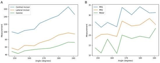
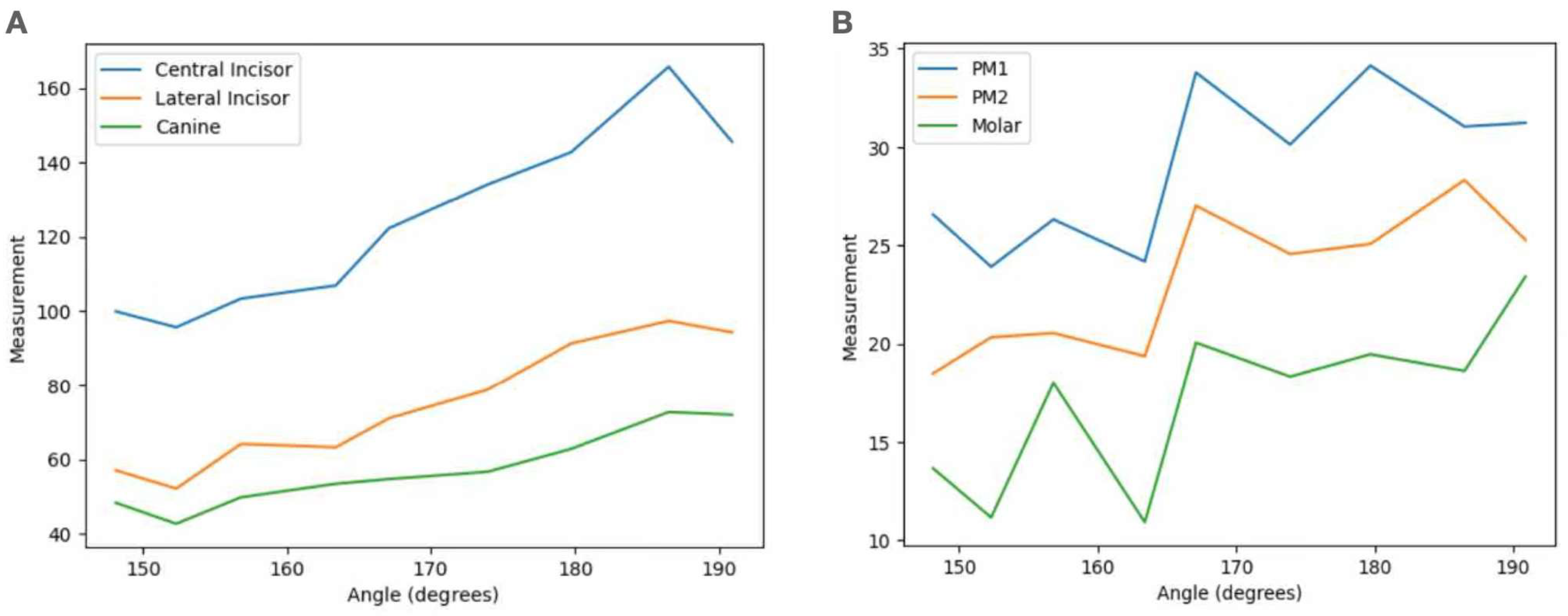
(A) Anterior teeth response to vertical angulation. Measurements of anterior teeth demonstrate a strong increasing trend with angulation, reaching peak values at approximately 186.5°, followed by a slight decline. (B) Posterior teeth respond to vertical angulation. Posterior teeth exhibit less pronounced changes in measurement with angulation, with an earlier plateau and reduced variability compared to anterior teeth.
Central and lateral incisors showed a progressive increase in projected surface area with increasing vertical angulation, reaching peak values at approximately 186.5°. This pattern is clearly illustrated in Figure 8A, where anterior teeth exhibit a steep upward trajectory followed by a plateau at higher angulations, reflecting increased visibility at superior camera positions.
Although graphical trends in Figure 8A suggest a similar directional increase for canines, this relationship did not reach statistical significance. This finding should be interpreted cautiously, as the absence of statistical significance may reflect a smaller effect size, greater variability, or limited statistical power rather than definitive evidence of angular independence.
In contrast, posterior teeth demonstrated a different response pattern. As shown in Figure 8B, first premolars exhibited peak projected surface area within a mid-to-superior angulation range (approximately 169–180°), whereas second premolars and molars reached maximal projected surface area at lower angulations (approximately 152.3°), corresponding to inferior camera positioning.
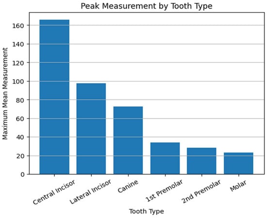
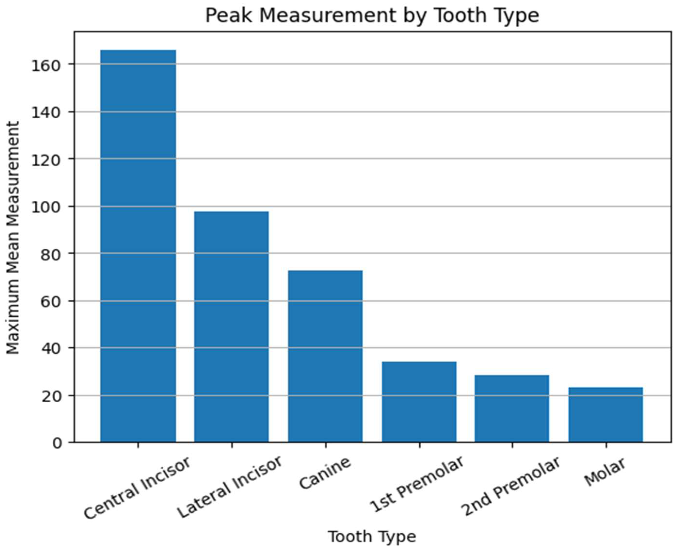
To translate these trends into discrete reference points for each tooth group, the angulations associated with maximal projected surface area in this experimental setting were identified as follows: 167.1° for central incisors, 186.5° for lateral incisors, 173.9° for canines, and 179.7° for PM1. For PM2 and molars, an angle of 152.3° yielded maximal surface visibility (Figure 9). These values correspond to the angles at which the maximum mean surface area was experimentally observed for each tooth type across all casts and should be interpreted as preliminary rather than prescriptive clinical guidelines.
Figure 9.
Bar graph illustrating the maximum mean surface area recorded for each tooth type and the angulation at which peak measurement occurred. Anterior teeth peak at higher angulations (~186.5°), whereas posterior teeth peak at lower angulations.
Collectively, these results demonstrate a spatially dependent response to vertical camera angulation, with anterior teeth (central incisors through first premolars) showing increased projected surface area at superior angulations, and posterior teeth (second premolars and molars) demonstrating greater representation at inferior angulations. This opposing trend across the dental arch is visually summarized in Figure 7.
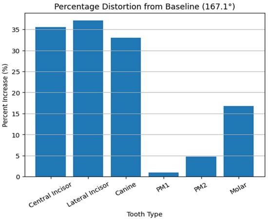
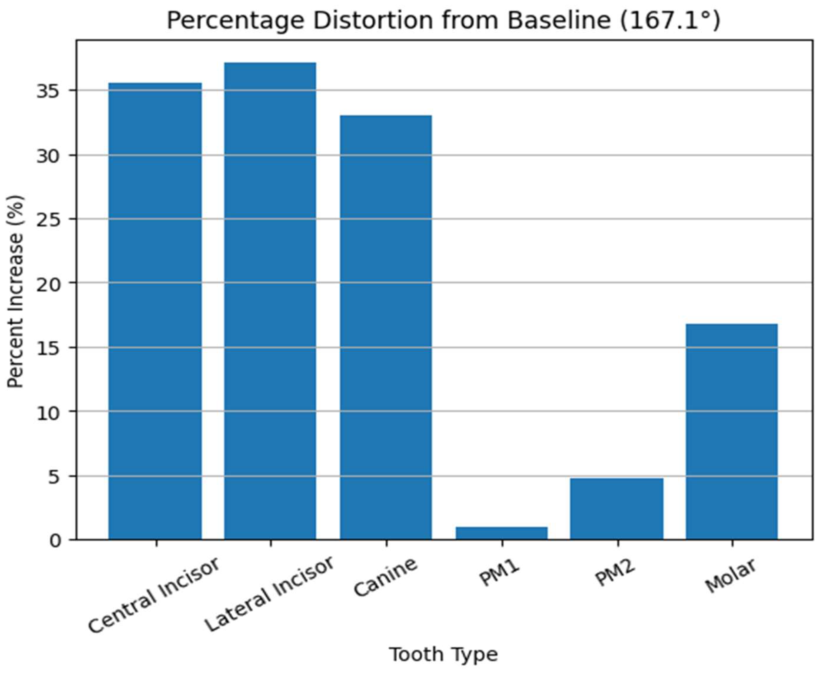
The magnitude of angular influence demonstrated a region-specific pattern, with anterior and posterior segments exhibiting inverse trends relative to the occlusal plane. This suggests that vertical angulation does not uniformly scale the dental arch, but rather induces non-linear, spatially heterogeneous distortion. Relative to the SOPA reference angle (167.1°), anterior teeth demonstrated increases in projected surface area of approximately 30–40%, whereas posterior teeth exhibited more modest changes of approximately 5–20% (Figure 10).
Figure 10.
Bar graph illustrating the percentage increase in measured surface area at peak angulation relative to the baseline (167.1°). Anterior teeth demonstrate substantially greater distortion (approximately 30–40%) compared to posterior teeth (approximately 5–20%), indicating region-specific sensitivity to vertical camera angulation.
Although canine measurements were not statistically significant, the observed trend suggests potential transitional behavior within the dental arch. However, this interpretation remains exploratory and requires confirmation in larger and more diverse samples.
4. Discussion
The findings of this study are based on controlled experimental measurements of projection-induced geometric distortion in two-dimensional dental images. While the implications of these findings extend to digital workflows and artificial intelligence (AI)-assisted systems, it is important to distinguish between results directly supported by the present data and forward-looking conceptual applications. The present study demonstrates that vertical camera angulation is not purely a photographic variable, but a geometric determinant within digital dental workflows. By quantifying the relationship between angulation and perceived tooth surface area, this work establishes that 2D photographic data are inherently angle-dependent representations rather than neutral projections of anatomical reality, providing a quantitative basis for understanding projection-dependent discrepancies in 2D dental images used in CAD/CAM workflows. The findings provide a foundation for the future development of AI-assisted image adjustment methods to improve consistency when integrating 2D photographs with 3D intraoral scan data in digital prosthetic design. Importantly, the present study does not introduce an AI-based correction system, but rather defines the geometric conditions necessary for such systems to operate reliably. This behavior is consistent with perspective projection, where depth variation relative to the imaging plane produces non-uniform scaling across the object [15,16].
From a geometric standpoint, the observed variations in tooth area reflect perspective distortion governed by projection geometry. When the camera is positioned above the standardized occlusal plane angle (SOPA), anterior teeth appear relatively magnified due to reduced foreshortening, whereas posterior structures appear compressed. Conversely, inferior angulation enhances posterior visibility at the expense of anterior proportional accuracy. This bidirectional distortion highlights that no single 2D image can simultaneously preserve geometric consistency across the entire dental arch [15,16].
Importantly, quantitative analysis demonstrated that this distortion is not uniform across the dental arch but exhibits a region-specific magnitude. Anterior teeth showed substantially greater sensitivity to vertical angulation, with relative increases in apparent surface area reaching approximately 30–40% at peak angulations, whereas posterior teeth demonstrated more modest changes, typically ranging from approximately 5–20%. This differential response confirms that projection distortion is both non-linear and tooth-dependent, reinforcing that a single 2D image cannot simultaneously preserve proportional accuracy across anterior and posterior segments (Figure 10).
These findings carry significant implications for CAD/CAM-driven prosthetic design, where 2D images are routinely merged with 3D intraoral scans to guide esthetic planning (Figure 2) [8,9]. In current workflows, clinicians often assume that frontal photographs provide a reliable reference for tooth proportion, gingival architecture, and smile arc design [17,18]. However, the present data indicate that such assumptions may be inherently limited unless camera angulation is rigorously standardized or computationally corrected [8,9]. Within contemporary digital workflows, this limitation becomes increasingly relevant as treatment planning relies on the integration of multiple data sources, including photographic records, intraoral scans, and virtual design environments. Discrepancies introduced at the level of image acquisition may propagate through CAD/CAM processes, ultimately influencing prosthetic design accuracy and esthetic outcomes [1,2,3,4].
More importantly, this limitation carries over into AI-driven dental workflows, where many learning-based systems assume that input images are geometrically consistent. In reality, images are not just flat 2D pictures; they are projections of a 3D structure captured from a specific camera position and angle. When the camera orientation changes, such as with vertical angulation, the same anatomy can appear differently due to perspective effects like scaling and foreshortening. As a result, the learned representations may entangle anatomical structure with acquisition geometry, introducing bias and reducing robustness when models are deployed across images captured under heterogeneous viewing conditions.
Foundational work in neural radiance fields (NeRF) has demonstrated that image formation can be modeled as a continuous function mapping spatial location and viewing direction to radiance and density, enabling reconstruction of scene geometry and synthesis of novel viewpoints [23,24]. Building upon this paradigm, recent 3D-aware generative models have shown that disentangling scene structure from viewpoint is essential for achieving consistent and generalizable representations. For example, StyleNeRF integrates radiance field representations with generative architectures to enable explicit control over camera pose while preserving multi-view consistency [25], while StyleSDF demonstrates that jointly modeling geometry and appearance leads to view-consistent high-resolution synthesis [26]. These approaches collectively highlight that accurate visual understanding depends on preserving geometric coherence across viewpoints, rather than relying solely on pixel-level correlations.
In this context, vertical camera angulation in dental imaging can be interpreted as an unparameterized perturbation in the imaging system, introducing systematic, geometry-induced variability in the observed feature space that is decoupled from the underlying anatomical structure. From a machine learning perspective, this corresponds to a structured domain shift, where identical anatomical structures are encoded differently due to acquisition geometry rather than biological variation. Such discrepancies violate the assumption of feature stability and may reduce model generalizability across datasets acquired under heterogeneous conditions.
This challenge is consistent with broader observations in medical imaging AI, where performance degradation is often attributed to dataset bias, hidden stratification, and variability in acquisition protocols [27,28]. In these settings, models may achieve high aggregate accuracy while failing in clinically meaningful subgroups, highlighting the importance of explicitly modeling sources of variability not represented in the training data.
From an algorithmic standpoint, vertical camera angulation introduces a structured geometric variable that perturbs the image formation process. Unlike stochastic noise, this perturbation follows a deterministic transformation governed by camera pose. Consequently, identical anatomical structures may be mapped to different feature representations depending on the projection angle, effectively introducing systematic encoding inconsistency within the dataset.
In modern neural rendering frameworks, such variability is explicitly modeled through camera-conditioned representations, in which the viewpoint is incorporated as an integral component of the generative process. Geometry-aware neural rendering approaches, including epipolar-based attention mechanisms, leverage known relationships between camera viewpoints to enforce spatial consistency across images [29]. These methods demonstrate that reliable image synthesis and interpretation depend on explicitly encoding geometric relationships, not treating images as independent observations.
Consequently, future AI-driven dental systems may benefit from incorporating geometry-aware preprocessing pipelines that explicitly model the relationship between camera pose and image formation. In addition to geometry-aware preprocessing, domain adaptation strategies may provide a complementary approach to address variability in imaging conditions. Because AI systems are inherently data-driven, their performance depends on the consistency of input data. Variations in angulation, lighting, and acquisition protocols across clinical environments may therefore limit model generalizability. Domain adaptation techniques aim to improve robustness across heterogeneous datasets by aligning feature distributions between domains. For example, domain-adaptive Faster R-CNN frameworks have demonstrated improved cross-domain object detection performance [30], while transformer-based domain adaptation models have shown effectiveness in adapting to diverse imaging environments [31]. Incorporating such strategies into dental imaging pipelines may enhance the reliability and scalability of AI-assisted image correction in clinical practice. In computer vision, this principle is formalized through camera calibration, neural rendering, and hybrid explicit–implicit scene representations, where geometry and appearance are jointly optimized under known projection constraints [32,33].
For example, hybrid generative frameworks decouple feature generation from rendering to preserve both geometric consistency and high-resolution detail, enabling controllable and multi-view-consistent synthesis [32]. Similarly, multi-object scene representations enforce alignment between foreground, background, and camera pose to maintain coherence across views [33]. Translating these principles into dental imaging suggests that projection-induced distortion should not be treated as noise, but as a geometric variable requiring explicit modeling within the computational pipeline.
Furthermore, recent work on neural radiance fields highlights the sensitivity of learned representations to incomplete or inconsistent viewpoint sampling. For instance, RegNeRF demonstrates that sparse or misaligned input views can degrade reconstruction quality, necessitating explicit regularization of geometry and appearance to maintain consistency [23]. This observation is particularly relevant in dental imaging, where photographic acquisition is often limited to a small number of views with variable angulation. Without explicit geometric normalization, such variability may propagate through the learning process and manifest as instability in downstream predictions.
Collectively, these findings indicate that the central challenge in integrating two-dimensional dental photography into AI-driven workflows is not simply data availability, but geometric alignment across the imaging pipeline. Contemporary 3D-aware models demonstrate that consistent representation emerges only when camera pose, scene geometry, and image formation are jointly considered. In the absence of such alignment, projection-induced distortion becomes embedded within learned representations, limiting both model reliability and clinical interpretability. The present study addresses this gap by defining vertical camera angulation as a quantifiable and controllable geometric variable, thereby establishing a foundation for alignment-aware computational foundations in digital dentistry.
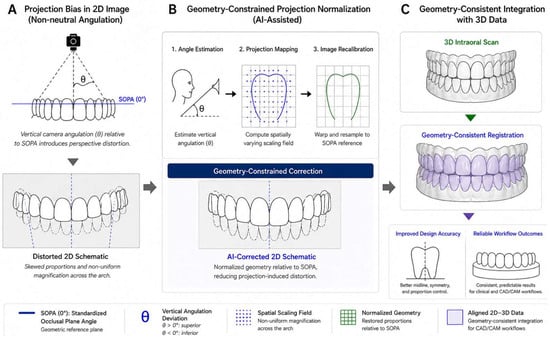
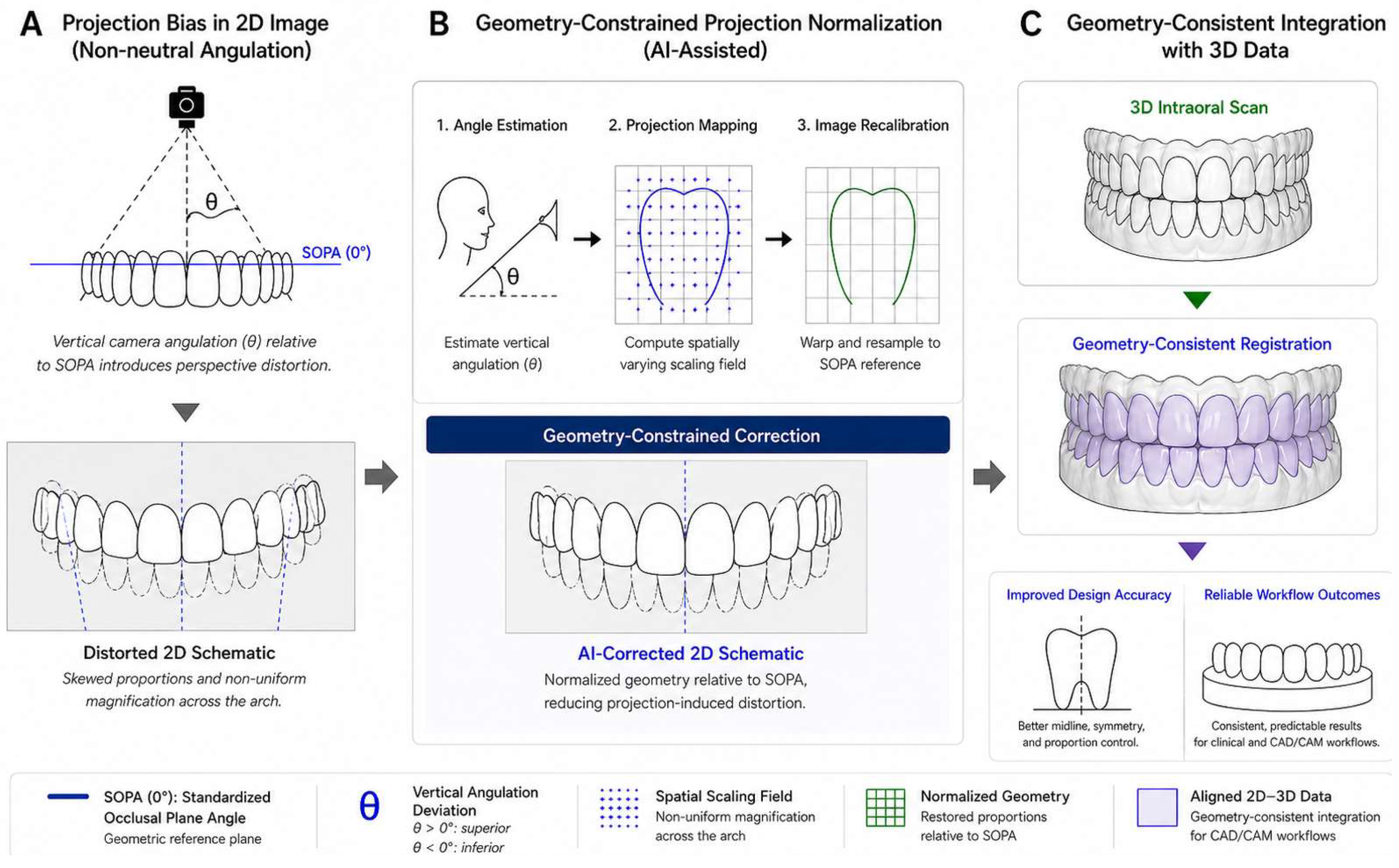
Accordingly, this study introduces a critical opportunity: the development of AI-assisted geometric adjustment strategies for 2D dental images. To conceptualize this translational pathway, a geometry-aware computational workflow for projection correction and 2D–3D integration is illustrated (Figure 11). These observations suggest that dental photography may be reframed as a controllable input variable within digital processing pipelines, rather than a passive documentation modality. By leveraging known geometric references—such as SOPA—and integrating them with IOS-derived 3D data, future systems could perform projection-based adjustment, normalizing distorted images into a standardized geometric space prior to CAD integration [1,10,11]. This would enable more consistent integration of 2D photographs within computational workflows. This approach parallels recent advances in neural rendering and radiance field models, where explicit modeling of viewpoint enables consistent reconstruction and synthesis across varying perspectives [23,24].
Figure 11.
Geometry-aware projection normalization enabling 2D–3D reconstruction in digital dentistry. Schematic representation of a geometry-constrained computational pipeline for correcting projection-induced distortion in two-dimensional (2D) dental images and facilitating integration with three-dimensional (3D) datasets. (A) A frontal photograph acquired under non-standardized vertical camera angulation represents a perspective projection rather than a geometrically neutral view, introducing spatially non-uniform distortion relative to the standardized occlusal plane angle (SOPA). (B) The image is processed through a geometry-aware normalization protocol, in which angular deviation and spatial scaling fields are estimated and corrected to restore geometric consistency; artificial intelligence may assist in parameter estimation but operates within a defined projection model. (C) The normalized 2D representation is subsequently aligned with 3D intraoral scan data, enabling geometry-consistent registration, improved prosthetic reconstruction accuracy, and more reliable CAD/CAM workflow outcomes. This schematic emphasizes that robust 2D–3D reconstruction is contingent upon explicit correction of acquisition-dependent projection geometry.
To further contextualize the computational pathway illustrated in Figure 11, the proposed correction process can be interpreted using principles of perspective projection geometry. Under a pinhole camera model, three-dimensional points are mapped onto a two-dimensional image plane based on intrinsic and extrinsic camera parameters. Variations in vertical camera angulation correspond to changes in camera orientation, resulting in non-uniform scaling across the dental arch. Accordingly, projection-induced distortion may be approximated by estimating the camera pose relative to a known reference, such as the standardized occlusal plane angle (SOPA), followed by applying an inverse transformation to normalize the image. For approximately planar regions, this may be simplified using homography-based mapping, a standard method in computer vision for perspective correction [15,16]. Although a full implementation is beyond the scope of the present study, this formulation establishes a geometric basis for future algorithmic or AI-assisted correction approaches.
At present, although 3D facial scanning technologies offer a more accurate alternative, their adoption remains limited in routine practice [4,5]. Consequently, improving the reliability of 2D image integration represents a high-impact and immediately translatable advancement. The current findings provide the foundational dataset necessary to inform such developments [1,2,3,4].
The lack of statistically significant variation in canine measurements may reflect a smaller effect size or greater variability in this region; however, this observation should be interpreted cautiously and requires confirmation in larger samples. This finding also highlights the potential value of multi-planar imaging strategies, as canine morphology may be more accurately captured in oblique or lateral views. Such projection-dependent variability may represent an unmodeled source of variance in image-based training datasets. Future investigations incorporating multi-view reconstruction and AI-based fusion techniques could further enhance the completeness of digital representations.
Future work may extend this logic toward multi-view reconstruction and AI-based fusion of 2D and 3D datasets, enabling dynamic correction of projection-induced distortion across different imaging modalities. Additionally, integration with real-time feedback systems during image acquisition could allow clinicians to achieve geometrically optimized photographs at the point of care.
Several practical limitations should be acknowledged. The study used static casts under controlled conditions, which may not fully replicate soft-tissue dynamics and patient-specific variability. Additionally, only frontal-plane images were analyzed, whereas real-world workflows often involve multiple photographic perspectives. Furthermore, the use of in vitro casts excludes the influence of soft tissue structures, including lips, cheeks, and gingival dynamics, which may affect visibility, shadowing, and perceived tooth proportions in clinical photography. Patient-related factors such as movement, posture variability, and facial expression were not represented in this controlled setting and may introduce additional variability in real-world image acquisition. Lighting conditions were also standardized in this study to isolate the effect of vertical angulation; however, variations in illumination intensity, direction, and shadow commonly encountered in clinical environments may further influence image-based measurements and should be considered in future investigations. In addition, operator-dependent variability, including camera positioning, angulation consistency, and handling technique, was minimized through controlled acquisition protocols in this study but may represent a significant source of variability in routine clinical practice. In addition, because the sample consisted of 14 fully dentate casts with relatively regular occlusal relationships, the findings may not fully apply to patients with irregular occlusal planes, crowding, rotations, spacing, severe wear, restorations, missing teeth, or altered arch forms. Nonetheless, the controlled design enabled isolation of vertical angulation as a primary variable, establishing a clear causal relationship. It should be emphasized that AI-based correction workflows discussed in this study are conceptual and were not implemented or validated within the present experimental logic.
Ultimately, these findings suggest that dental photography may be reframed as a data-acquisition and interpretation problem within a computational pipeline, not as a purely clinical documentation step. By identifying and quantifying a key source of geometric distortion, it provides a foundation for the future development of standardized, AI-enhanced imaging protocols in digital dentistry.
5. Conclusions
In conclusion, vertical camera angulation introduces measurable geometric distortion in 2D dental images, influencing the apparent representation of dental structures. While certain angulations may enhance visualization of specific regions, these variations can introduce discrepancies when 2D images are integrated with 3D datasets in CAD/CAM workflows. Recognition of this projection-dependent variability may improve consistency in digital treatment planning and provide a quantitative basis for future geometry-aware calibration or AI-assisted image adjustment strategies.
Author Contributions
Conceptualization, Y.K.K. and R.L.; Methodology, L.B. and J.E.; Software, R.S.; Formal analysis, R.S.; Investigation, Y.K.K., L.B. and J.E.; Writing—original draft, G.M.; Writing—review & editing, Y.K.K., L.B., G.M., T.G.W. and R.L.; Supervision, Y.K.K. and R.L.; Project administration, Y.K.K. All authors have read and agreed to the published version of the manuscript.
Funding
This research received no external funding.
Institutional Review Board Statement
Not applicable.
Informed Consent Statement
Not applicable.
Data Availability Statement
The original contributions presented in this study are included in the article. Further inquiries can be directed to the corresponding author.
Conflicts of Interest
The authors declare no conflict of interest.
References
- Alghauli, M.A.; Aljohani, W.; Almutairi, S.; Aljohani, R.; Alqutaibi, A.Y. Advancements in digital data acquisition and CAD technology in Dentistry: Innovation, clinical Impact, and promising integration of artificial intelligence. Clin. eHealth 2025, 8, 32–52. [Google Scholar] [CrossRef] [Scilit]
- Joda, T.; Gallucci, G.O. The virtual patient in dental medicine. Clin. Oral Implant. Res. 2015, 26, 725–726. [Google Scholar] [CrossRef] [Scilit]
- Lepidi, L.; Kim, B.C.; Giberti, L.; Suriano, C.; Li, J.; Grande, F. The 4D virtual patient: A proof of concept in digital dentistry. J. Prosthet. Dent. 2024, 134, 1442–1445. [Google Scholar] [CrossRef] [Scilit]
- Watanabe, H.; Fellows, C.; An, H. Digital Technologies for Restorative Dentistry. Dent. Clin. N. Am. 2022, 66, 567–590. [Google Scholar] [CrossRef] [Scilit] [PubMed]
- Bhambhani, R.; Bhattacharya, J.; Sen, S.K. Digitization and its futuristic approach in prosthodontics. J. Indian Prosthodont. Soc. 2013, 13, 165–174. [Google Scholar] [CrossRef] [Scilit] [PubMed]
- Ahmad, I. Digital dental photography. Part 7: Extra-oral set-ups. Br. Dent. J. 2009, 207, 103–110. [Google Scholar] [CrossRef] [Scilit]
- Bengel, W. Standardization in dental photography. Int. Dent. J. 1985, 35, 210–217. [Google Scholar]
- Galibourg, A.; Brenes, C. Virtual smile design tip: From 2D to 3D design with free software. J. Prosthet. Dent. 2019, 121, 863–864. [Google Scholar] [CrossRef] [Scilit] [PubMed]
- Coachman, C.; Georg, R.; Bohner, L.; Rigo, L.C.; Sesma, N. Chairside 3D digital design and trial restoration workflow. J. Prosthet. Dent. 2020, 124, 514–520. [Google Scholar] [CrossRef] [Scilit]
- Schwendicke, F.; Samek, W.; Krois, J. Artificial intelligence in dentistry: Chances and challenges. J. Dent. Res. 2020, 99, 769–774. [Google Scholar] [CrossRef] [Scilit]
- Krois, J.; Ekert, T.; Meinhold, L.; Golla, T.; Kharbot, B.; Wittemeier, A.; Dörfer, C.; Schwendicke, F. Deep learning for the radiographic detection of periodontal bone loss. Sci. Rep. 2019, 9, 8495. [Google Scholar] [CrossRef] [Scilit] [PubMed]
- Elgarba, B.M.; Fontenele, R.C.; Tarce, M.; Jacobs, R. Artificial intelligence serving pre-surgical digital implant planning: A scoping review. J. Dent. 2024, 143, 104862. [Google Scholar] [CrossRef] [Scilit]
- Elgarba, B.M.; Fontenele, R.C.; Mangano, F.; Jacobs, R. Novel AI-based automated virtual implant placement: Artificial versus human intelligence. J. Dent. 2024, 147, 105146. [Google Scholar] [CrossRef] [Scilit]
- Ding, H.; Wu, J.; Zhao, W.; Matinlinna, J.P.; Burrow, M.F.; Tsoi, J.K. Artificial intelligence in dentistry—A review. Front. Dent. Med. 2023, 4, 1085251. [Google Scholar] [CrossRef] [Scilit]
- Hartley, R.; Zisserman, A. Multiple View Geometry in Computer Vision, 2nd ed.; Cambridge University Press: Cambridge, UK, 2003; pp. 262–278. [Google Scholar] [CrossRef] [Scilit]
- Szeliski, R. Computer Vision: Algorithms and Applications; Springer: London, UK, 2010. [Google Scholar]
- Springer, N.C.; Chang, C.; Fields, H.W.; Beck, F.M.; Firestone, A.R.; Rosenstiel, S.; Christensen, J.C. Smile esthetics from the layperson’s perspective. Am. J. Orthod. Dentofac. Orthop. 2011, 139, e91–e101. [Google Scholar] [CrossRef] [Scilit]
- Kattadiyil, M.T.; Goodacre, C.J.; Naylor, W.P.; Maveli, T.C. Esthetic smile preferences and the orientation of the maxillary occlusal plane. J. Prosthet. Dent. 2012, 108, 354–361. [Google Scholar] [CrossRef] [Scilit]
- Chen, H.; Zhang, K.; Lyu, P.; Li, H.; Zhang, L.; Wu, J.; Lee, C.-H. A deep learning approach to automatic teeth detection and numbering based on object detection in dental periapical films. Sci. Rep. 2019, 9, 3840. [Google Scholar] [CrossRef] [Scilit] [PubMed]
- Lee, J.-H.; Kim, D.-H.; Jeong, S.-N.; Choi, S.-H. Detection and diagnosis of dental caries using a deep learning-based convolutional neural network algorithm. J. Dent. 2018, 77, 106–111. [Google Scholar] [CrossRef] [Scilit]
- Miki, Y.; Muramatsu, C.; Hayashi, T.; Zhou, X.; Hara, T.; Katsumata, A.; Fujita, H. Classification of teeth in cone-beam CT using deep convolutional neural network. Comput. Biol. Med. 2017, 80, 24–29. [Google Scholar] [CrossRef] [Scilit] [PubMed]
- Zhang, S.; Wang, W.; Lu, B.; Lu, Z. High-fidelity 3D Buddhist sculpture reconstruction from single images using domain-adaptive diffusion. npj Herit. Sci. 2025, 13, 670. [Google Scholar] [CrossRef] [Scilit]
- Niemeyer, M.; Barron, J.T.; Mildenhall, B.; Sajjadi, M.S.M.; Geiger, A.; Radwan, N. RegNeRF: Regularizing Neural Radiance Fields for View Synthesis from Sparse Inputs. In 2022 IEEE/CVF Conference on Computer Vision and Pattern Recognition (CVPR); IEEE: Piscataway, NJ, USA, 2022; pp. 5470–5480. [Google Scholar] [CrossRef] [Scilit]
- Schwarz, K.; Liao, Y.; Niemeyer, M.; Geiger, A. GRAF: Generative Radiance Fields for 3D-Aware Image Synthesis. arXiv 2021, arXiv:2007.02442. [Google Scholar] [CrossRef] [Scilit]
- Gu, J.; Liu, L.; Wang, P.; Theobalt, C. StyleNeRF: A Style-based 3D-Aware Generator for High-resolution Image Synthesis. arXiv 2021, arXiv:2110.08985. [Google Scholar]
- Or-El, R.; Luo, X.; Shan, M.; Shechtman, E.; Park, J.J.; Kemelmacher-Shlizerman, I. StyleSDF: High-Resolution 3D-Consistent Image and Geometry Generation. arXiv 2022, arXiv:2112.11427. [Google Scholar]
- Varoquaux, G.; Cheplygina, V. Machine learning for medical imaging: Methodological failures and recommendations for the future. npj Digit. Med. 2022, 5, 48. [Google Scholar] [CrossRef] [Scilit] [PubMed]
- Oakden-Rayner, L.; Dunnmon, J.; Carneiro, G.; Re, C. Hidden stratification causes clinically meaningful failures in machine learning for medical imaging. In CHIL ’20: Proceedings of the ACM Conference on Health, Inference, and Learning; ACM: New York, NY, USA, 2020; pp. 151–159. [Google Scholar] [CrossRef] [Scilit]
- Tobin, J.; Zaremba, W.; Abbeel, P. Geometry-Aware Neural Rendering. Adv. Neural Inf. Process. Syst. 2019, 32, 11559–11569. [Google Scholar]
- Wang, S. Domain-adaptive faster R-CNN for non-PPE identification on construction sites from body-worn and general images. Sci. Rep. 2026, 16, 4793. [Google Scholar] [CrossRef] [Scilit] [PubMed]
- Wang, S. Domain adaptation using transformer models for automated detection of exterior cladding materials in street view images. Sci. Rep. 2025, 16, 2696. [Google Scholar] [CrossRef] [Scilit]
- Chan, E.R.; Lin, C.Z.; Chan, M.A.; Nagano, K.; Pan, B.; de Mello, S.; Gallo, O.; Guibas, L.; Tremblay, J.; Khamis, S.; et al. Efficient Geometry-aware 3D Generative Adversarial Networks. In 2022 IEEE/CVF Conference on Computer Vision and Pattern Recognition (CVPR); IEEE: Piscataway, NJ, USA, 2022; pp. 16102–16112. [Google Scholar] [CrossRef] [Scilit]
- Xue, Y.; Li, Y.; Singh, K.K.; Lee, Y.J. GIRAFFE HD: A High-Resolution 3D-Aware Generative Model. In 2022 IEEE/CVF Conference on Computer Vision and Pattern Recognition (CVPR); IEEE: Piscataway, NJ, USA, 2022; pp. 18445–18454. [Google Scholar] [CrossRef] [Scilit]

Disclaimer/Publisher’s Note: The statements, opinions and data contained in all publications are solely those of the individual author(s) and contributor(s) and not of MDPI and/or the editor(s). MDPI and/or the editor(s) disclaim responsibility for any injury to people or property resulting from any ideas, methods, instructions or products referred to in the content. |
© 2026 by the authors. Licensee MDPI, Basel, Switzerland. This article is an open access article distributed under the terms and conditions of the Creative Commons Attribution (CC BY) license.