


Abstract
This paper studies the influence of laser power and scanning speed through single laser scan tracks on AlNiCo5 and SS 304 substrates. Track morphologies and melt pool geometries were assessed to determine the prevailing melting modes. Cracking was observed only on AlNiCo5 substrates, while SS 304 substrates exhibited crack-free tracks, highlighting the advantages of its ductile FCC structure. Optimal laser powder bed fusion process parameters for AlNiCo5 fabrication were identified as 190 W and 600–900 mm/s for stable conduction melting, while for higher laser power processing, 270 W and 600–800 mm/s provided stable transition melting. Microhardness measurements, nanoindentation, and energy-dispersive X-ray spectroscopy were employed to analyze mechanical properties and compositional variation within the melt pools. Increased laser power led to noticeable dilution of the SS 304 substrate into the AlNiCo5 tracks, reducing the melt pool’s overall microhardness due to altered chemical composition. Nanoindentation analysis further confirmed localized mechanical heterogeneity within the melt pool, with Co- and Al-rich zones showing elevated nanohardness, elastic modulus, and resistance to plastic deformation (H/Er, H3/Er2), while substrate-diluted areas (Cr-enriched) exhibited softening linked to BCC-to-FCC phase transformation.
1. Introduction
Laser powder bed fusion (LPBF) is an additive manufacturing (AM) process that can create complicated structures from metallic powders. AlNiCo alloys have recently received renewed attention because of their rare earth element (REE)-free composition, great heat resistance qualities (up to 600 °C), stable magnetic properties over a wide temperature range, and high corrosion resistance [1,2]. The primary limitation of AlNiCo is its comparatively poor coercivity [3]. Currently, the highest magnetic properties achieved in commercial high-coercivity AlNiCo magnets are Br 8.0 T, Hc 2000 Oe, and (BH)max 6.0 MGOe [4]. To further increase the magnetic properties, additional research on AlNiCo materials is needed. Experimental screening is required to accelerate the development of novel environmentally benign materials, with compositions suitable for AM across multicomponent alloy phase spaces, while leveraging the competitive advantages given by AM, such as form complexities and microstructure engineering [5,6]. These efforts aim to develop novel anisotropic microstructures with enhanced coercivity, targeting (BH)max values exceeding 60 kJ/m3. This work contributes to the development of a more competitive and sustainable European industry by providing novel materials and production processes that bring REE products closer to market readiness while ensuring the cost-effectiveness of REE products [7].
Most hard magnetic alloys, such as NdFeB, are difficult to produce through LPBF because of the formation of cracks induced by the high cooling rates of the AM method [8,9,10,11]. LPBF uses a laser beam to scan a powder bed in order to build a part layer by layer. According to the authors [12,13,14], LPBF processing involves a complex interplay of physical phenomena, such as laser absorption and scattering, heat transfer, phase transitions, melt pool convection influenced by surface tension gradients, and material vaporization and emission. In study [15], it was shown that the balance between thermal conductivity and laser energy absorption during irradiation dictates whether melting occurs in keyhole or conduction mode.
In addition to optimizing the process parameters, it is essential to determine the origin of defects within LPBF components by characterizing their size, morphology, and distribution. The LPBF process involves extremely high thermal gradients (~106 K/m) and rapid solidification rates (~103–107 K/s), resulting in the development of an anisotropic, directionally solidified subgranular microstructure [16]. Because of large temperature gradients and diverse residual stresses, LPBF metallic materials frequently exhibit an anisotropic microstructure, including chemical segregation, non-equiaxed grains, and cellular microstructures [17,18]. This anisotropic microstructure results in a considerable change in mechanical properties compared to traditionally manufactured materials. The thermal gradient in LPBF is strongly influenced by key process parameters, such as laser power, scan speed, hatch spacing, layer thickness, scan strategy, and powder bed temperature [19,20]. The LPBF technology employs advanced metallurgical mechanisms that vary based on process parameters, chemical compositions, and material properties. Variations in parameter settings can markedly alter part quality, affecting both the microstructure and mechanical behavior of the manufactured component.
A very limited number of studies can be found in the literature that are dedicated to the processing of AlNiCo hard magnetic materials with the use of AM technologies, such as Direct Energy Deposition (DED) and Electron Beam Melting (EBM) [5,21]; even fewer studies are focused on the LPBF of AlNiCo5. In the work by Rinko et al. [22,23], a conventional powder processing route, including compaction, was used to produce Co-lean AlNiCo magnets. Fuhui et al. effectively produced AlNiCo5 samples using LPBF with a heated stage at 160 °C, attaining material density in excess of 98% [24,25]. Nevertheless, despite the significant improvements in density, the LPBF-processed AlNiCo5 samples exhibited surface defects, including pores and cracks [25,26]. A comparable condition was found when AlNiCo8 was treated via LPBF with a heated stage at 800 °C, with visible porosity [27,28]. Conversely, Shakirov et al. revealed that rigorous tuning of process parameters, notably employing settings at 190 W and 700 mm/s, produced AlNiCo5 samples with reduced porosity and cracks [26]. These results highlight the critical importance of carefully optimizing process parameters to produce defect-free AlNiCo magnets. In LPBF-manufactured AlNiCo5 with a heated stage of 160 °C, increasing the laser energy density initially increased the compressive strength, followed by a decrease after 65 J/mm3 laser input energy. Meanwhile, hardness continued to rise, reaching a maximum at 100 J/mm3, demonstrating the complex relationship between energy input and the resulting mechanical properties [25]. All samples produced with LPBF initially showed cracks, which were minimized through the adjustment of process parameters. All additively manufactured samples displayed an equiaxed microstructure. Additive manufacturing offers significant potential for further development and processing improvements in AlNiCo materials.
In AlNiCo alloys, a columnar grain structure oriented along the <100> crystallographic direction is especially favorable for achieving enhanced magnetic properties [29,30]. Process factors have a significant impact on the crystallographic structure and grain shape of AM alloys. Platform temperature, laser power, scan speed, layer thickness, and cooling rate are all process characteristics that have a direct impact on the thermokinetics of the process [31,32]. These process parameters determine the solidification rate, melt pool size and shape, and temperature distribution within the melt pool [33]. Optimizing AM process parameters enables control over grain structure and crystallographic texture, producing materials with tailored mechanical and magnetic properties.
This study examines how variations in laser power and scan speed influence the melting and solidification behavior of AlNiCo5 under laser irradiation. The current literature provides limited insight into the response of AlNiCo alloys to laser processing in LPBF. While most existing single-track experiments focus on defect formation and delineating stable melt zones, these studies have broader applications. For instance, they can serve to validate simulation models and assess the feasibility of producing novel powder blends optimized for LPBF, such as cobalt-lean alloys or compositions with minor Ti and Cu additions. Furthermore, this study is carried out to explore the development of cracks resulting from the fusion of the single scan track with the substrate, as well as the influence of powder characteristics (both physical and morphological) on track formation. This approach enhances traditional methods of minimizing cracking in LPBF components by performing extended experiments for parameter optimization.
To evaluate how the AM process influences mechanical performance, localized property measurements are essential. This work is divided into two sections: the first examines fusion lines on AlNiCo5 substrates without powder, and the second examines single tracks produced with powders of AlNiCo5 and stainless steel(SS) 304 substrates. Austenitic stainless steel SS 304 is widely used as a substrate for Fe-based and steel alloys because of its well-established metallurgical compatibility in welding and fusion-based processes. Furthermore, its widespread availability, ease of supply, and relatively low cost make it a practical and efficient choice for substrate material in LPBF. The depth and width of the tracks, as well as the response to varying laser power and scan speeds, were determined. The consistency and uniformity of the scan tracks were also investigated. The micro- and nanohardness of both the melt pools and the substrates were measured and correlated to the microstructure and chemical composition distribution. This paper, therefore, contributes to the available research in the field of AM in novel aspects by filling these gaps in the literature.
A key motivation for this research in LPBF is its potential to produce lightweight, geometrically sophisticated AlNiCo5 magnets that meet the demanding requirements of the aerospace and automotive industries. An additional motive is the need to produce robust and sustainable REE-free permanent magnets (PMs) for emergent energy and mobility applications [34,35]. This concept relies on novel compositions of AlNiCo and hard magnetic high-entropy alloys undergoing similar spinodal decompositions [36,37,38], processed by additive manufacturing (AM).
2. Materials and Methods
2.1. Powder Feedstock
Gas-atomized AlNiCo5 metallic powder was used as the feedstock. The metal powder was supplied by CEIT-BRTA (Technology Centre, Basque Research and Technology Alliance, Donostia-San Sebastián, Spain). The powder was produced based on the typical chemical composition given by the ASTM A1070-16(2022) standard [39] for AlNiCo5 alloy. The chemical composition of the AlNiCo5 powder was verified using electron dispersive spectroscopy (EDS) with 0.1% accuracy, performed on a Phenom ProX (Thermo-Fisher Scientific Inc., Waltham, MA, USA) scanning electron microscope (SEM) operating at an acceleration voltage of 20 kV. The powder particle size distribution (PSD) was also assessed using SEM combined with Phenom ParticleMetric image analysis software (V1.2.2.0, Thermo Fisher Scientific). To ensure statistical significance, 120 SEM micrographs were assessed. The micrographs were acquired through automated image mapping, each with a field of view of 500 μm, and subsequently analyzed using image analysis software.
2.2. LPBF Equipment and Process Development
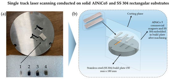
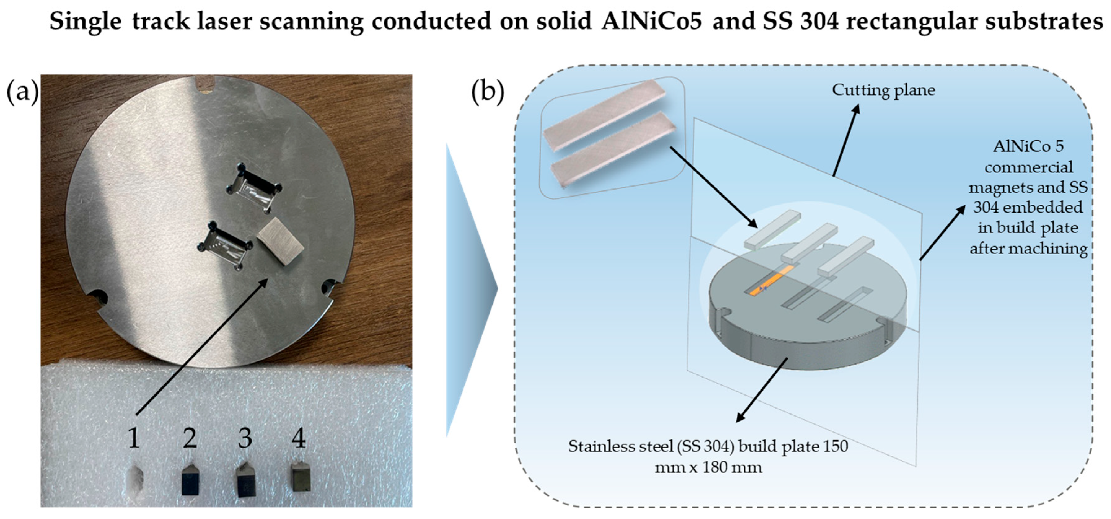
The single-track experiments were performed using an LPBF machine (INTECH, SF1 iFusion150, Intech Additive Solutions Ltd., Bangalore, India), equipped with a 500 W ytterbium-fiber laser operating at 1064 nm and a laser spot size of 80 μm. The single scan tracks were processed on four rectangular substrates, two of them made from AlNiCo5 and the other two from SS 304 with dimensions of 12.4 × 21.6 × 9.2 mm (L × W × H). The rectangular substrates were inserted in slots, specifically machined for the experiments, on a 150 mm diameter platform composed of SS 304 stainless steel, as shown in Figure 1. The chemical composition of the as-received SS 304 stainless steel substrates is presented in Table 1. Two of the AlNiCo5 rectangular substrates was as-cast, and the other two were subjected to thermomagnetic treatment, which promotes spinodal decomposition; hereafter, it will be referred to as ‘finished’.
Figure 1.
Image of the (a) 304 stainless steel machined plate with four rectangular AlNiCo5 magnets used as substrates, 1 and 2 in as-cast condition, 3 and 4 in finished condition (b) schematic illustrating the placement of the AlNiCo5 and SS 304 stainless steel substrates within the machined slots of the 304 stainless steel build plate.
Table 1.
Chemical composition of the SS 304 substrates.
The build plate was maintained at 150 °C, and the chamber was kept under an inert argon atmosphere (Grade 5.0) with oxygen below 0.5 ppm. The linear energy density (LED) was calculated (Equation (1)) to determine the optimal process parameters.
where P is the laser power in W, V is the laser scan speed in mm/s, and t is the layer thickness of the powder in mm. The selection of processing parameters was based on previous studies found in the literature, where laser power and scan speed were varied, as shown in Table 2.
Table 2.
Processing parameters of LPBF Alnico5 grades found in the literature.
A design of experiment (DoE) was carried out, varying laser power from 170 to 210 W and scan speed from 600 to 900 mm/s, to investigate the response of two AlNiCo5 substrates (as-cast and finished) to laser irradiation along single fusion lines. The DoE is analytically presented in Table 3.
Table 3.
Design of experiment and single scan track processing parameters on AlNiCo5 and SS 304 substrates.
The same DoE and set of parameters (Table 3) were used to fabricate single tracks on AlNiCo5 substrates with AlNiCo5 powder to assess the melt pool shape and dimensions of the tracks with powder. For the powder-coated AlNiCo5 substrates, the use of a 40 μm layer thickness was selected as it is a standard thickness used for LPBF processing of various metals and alloys and adopted by the industry. The same set of parameters (Table 3) applied to the AlNiCo5 substrates was also employed for the SS 304 substrate coated with AlNiCo5 powder to evaluate the track morphology and bead dimensions using a different substrate material. Furthermore, a separate DoE was additionally used for the experiments on SS 304 substrate coated with AlNiCo5 powder. A higher range of laser power and scan speed was employed for this experiment, also considering the lower thermal conductivity of SS 304. The selected process parameters are presented in Table 4.
Table 4.
Design of experiment and single scan track processing parameters of AlNiCo5 powder on SS 304 substrate using higher laser power values.
2.3. Metallographic Preparation—Scanning Electron Microscopy (SEM) and Optical Microscopy (OM)
After the single scan tracks were completed on the substrates, they were removed from the slots, and the top views of the tracks were examined in terms of their morphology. The top view of the single scan tracks was depicted using SEM; then, the substrates were cross-sectioned transverse to the single tracks’ length at three locations well away from the two ends of the tracks using a micro-cutting machine (Mecatome T210, precision micro-cutting machine, PRESI, Paris, France). Metallographic preparation was then carried out to reveal the melt pool boundaries of the tracks and to measure the melt pool dimensions. The samples were mounted, ground up to 2000 grit, and polished using a 3 μm diamond paste, followed by a final polish with a 1 μm diamond paste. The final metallographic step involved chemical etching using Nital 6% v/v (6 mL HNO3 and 94 mL C2H5OH) for tracks on the AlNiCo5 substrate and Marble’s Etchant (10 g Copper Sulphate PentaHydrate—CuSO45H2O, 50 mL HCL, 50 mL H2O) for tracks on the SS 304 substrate to reveal the melt pool boundaries. For the dimensional measurements, an Optical Microscope (OM) equipped with an 18 MP Digital Camera from AmScope (United Scope LLC., Irvine, CA, USA) was used, acquiring images at magnifications ranging from 100× up to 500×.
Adopting a comparative approach between single scan track experiments on a bare substrate and a substrate coated with powder presents several advantages in optimizing the LPBF process, as shown in Table 5. Bare substrate experiments facilitate a clear understanding of the thermal and mechanical behavior during the fusion process while minimizing external variables. In contrast, experiments on a powdered substrate provide insights into the interaction between the laser and powder characteristics, revealing how different physical and morphological attributes influence track formation and crack development. This dual setup enables researchers to identify optimal parameters effectively, leading to enhanced component quality, reduced cracking, and overall improved performance in additive manufacturing.
Table 5.
Comparison table between single scan track experiments on a bare substrate and a substrate coated with powder, showing how each setup provides valuable insights into optimizing the LPBF process.
2.4. Microhardness
Microhardness measurements were acquired according to ASTM E384-17 [40], with the use of an Innovatest FALCON 400 G2 machine (INNOVATEST Europe BV, Maastricht, The Netherlands). Vickers microhardness was measured with an applied load of 0.1 Kgf and a dwell time of 10 s. Microhardness measurements were carried out on defect-free and well-formed melt pools, characterized by the absence of cracks and pores. Three measurements were taken per track from three individual cross-sections to assess local uniformity and reproducibility of hardness along the track.
2.5. Nanohardness
Nanoindentation (NI) testing was performed to assess the hardness distribution within and around the melt pool of the track, where chemical inhomogeneities were clearly observed via EDS. Nanoindentation experiments were conducted using a Hysitron TS 77 Select Nanoindenter (Bruker, Minneapolis, MN, USA), equipped with a high-load transducer capable of reaching forces up to 1 N and displacements up to 80 µm. A Berkovich diamond indenter was used for all measurements (half angle: 65.27°, included angle: 142.3°; C0: 24.5; Young’s modulus: 1140 GPa; Poisson’s ratio: 0.07). All tests were performed under load-controlled conditions, with the maximum load set to 200 µN. The loading protocol consisted of 40 s loading, a 3 s hold at peak load, and 40 s unloading, and was applied uniformly across all measurements under ambient conditions.
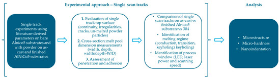
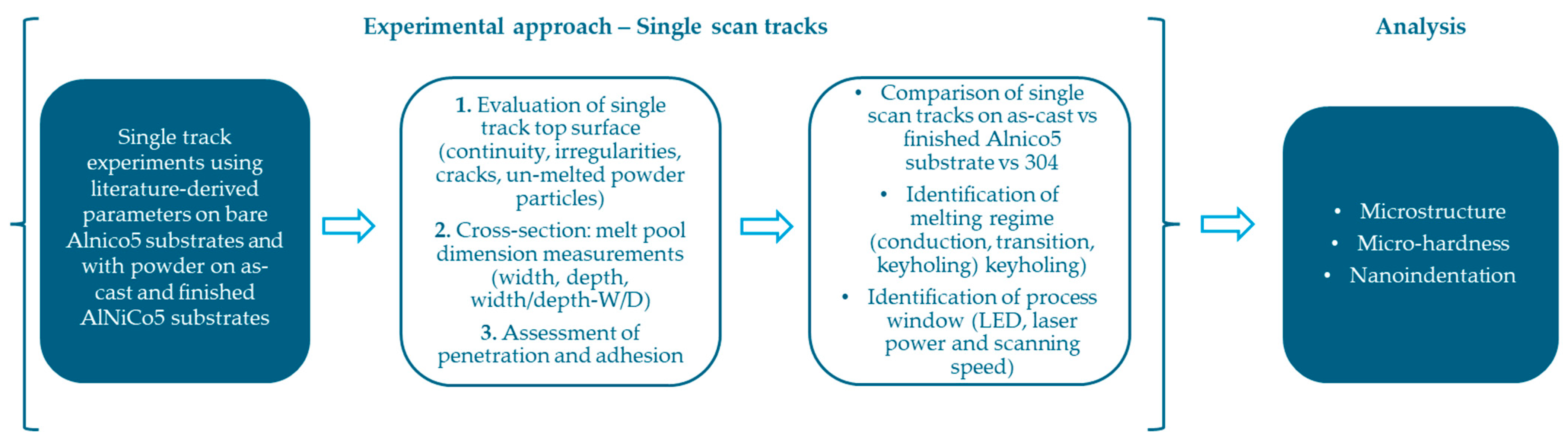
Two distinct regions of the track were investigated. The first targeted the interface between the AlNiCo5 melt pool and the adjacent substrate—referred to here as the AlNiCo5 transition zone—where a 10 × 20 (200 indents) indentation grid was applied with a 10 μm spacing between indents. The second region corresponded to the AlNiCo5-rich zone, located on the top surface of the AlNiCo5 melt pool. In this area, a 3 × 8 (24 indents) array was applied, also with a 10 μm spacing. The number of indents for both regions was selected and applied to ensure consistent spatial coverage and local mechanical mapping. Subsequently, a correlation between SEM/EDS analysis and NI results was conducted by overlapping EDS elemental maps of the melt pool with the NI region, aiming to link the local inhomogeneities with the measured mechanical response. EDS elemental mapping was performed using an acceleration voltage of 20 kV as well as indicative local EDS spot analyses on regions of interest (e.g., substrate, AlNiCo5-rich zone/transition zone). The overall experimental methodology for this study is summarized and presented in Figure 2.
Figure 2.
Graphical illustration of the experimental method and testing implemented in this study.
3. Results
3.1. Powder Feedstock Analysis
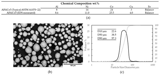
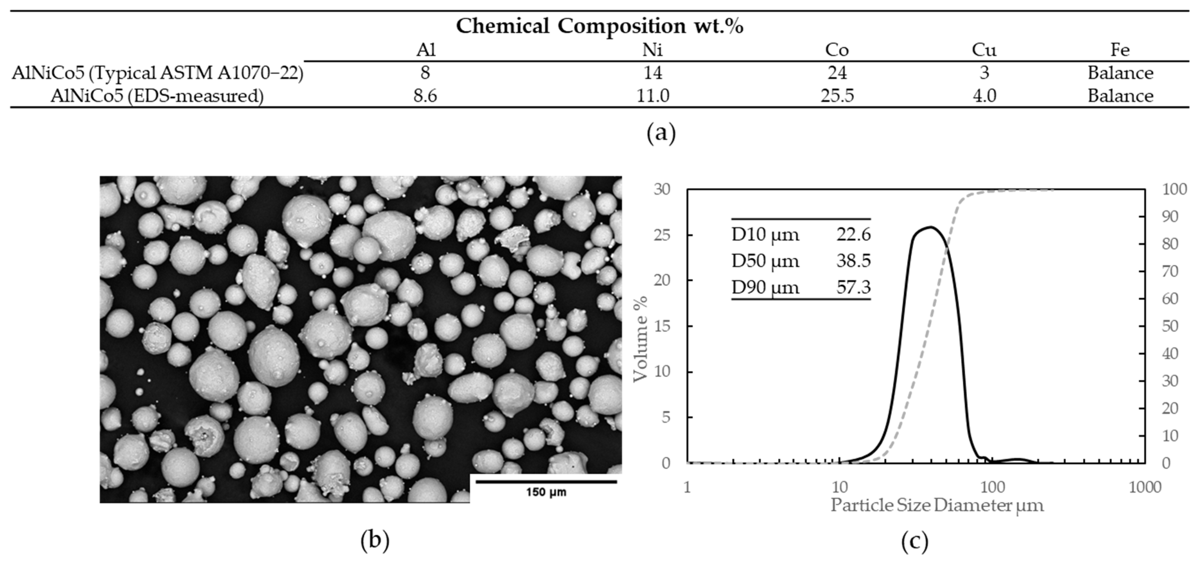
The typical and EDS-measured chemical compositions, as well as the particle size distribution (PSD) of the powder used for the experiments, are presented in Figure 3. The indicative EDS measurement aligns with the typical chemical composition of AlNiCo5 powder, and the powder’s PSD falls within the suitable range (20–53 μm) for LPBF processing.
Figure 3.
(a) Typical and indicative EDS-measured chemical composition of AlNiCo5 powder. (b) SEM micrograph indicating the morphology of AlNiCo5 powder. (c) Particle size distribution (PSD) of AlNiCo5 powder.
3.2. Single Scan Tracks with No Powder (On AlNiCo5 Bare Substrate)
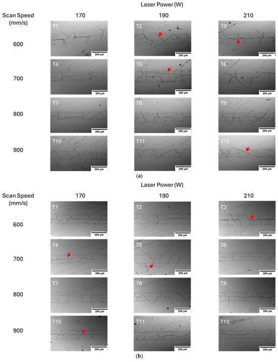
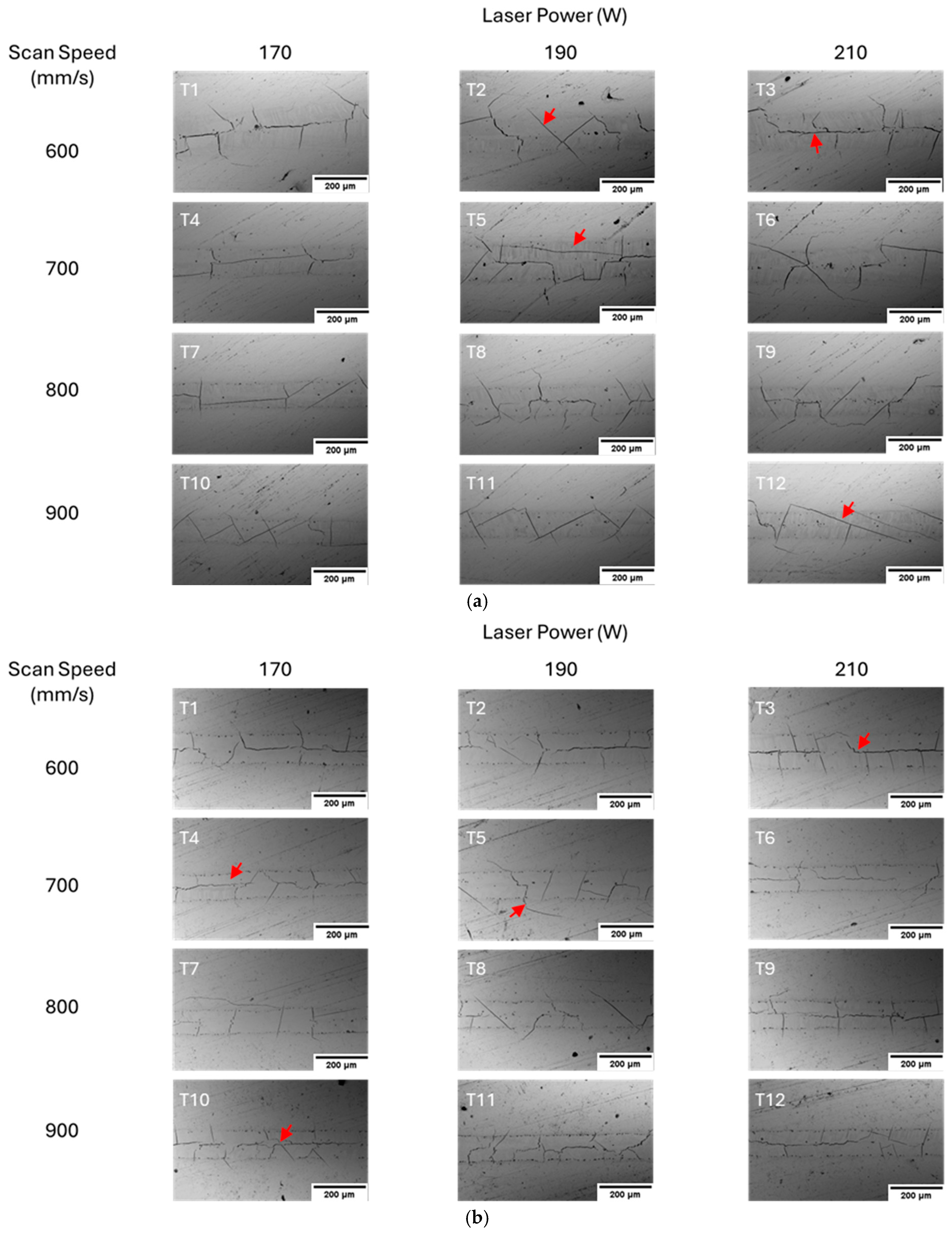
Single scan tracks on bare AlNiCo5 substrates using various laser power and scan speed values were produced by LPBF. The scan track width decreased with increasing scan speed, and the top-view optical images reveal extensive cracking regardless of the process parameters used (Figure 4). Cross-sections of the melt pools are presented in Figure 5. As shown in Figure 5a, most cross-sections on the as-cast AlNiCo5 reveal cracks within the melt pools. Tracks 8, 11, and 12 are the only exceptions with no presence of cracks. Defect-free melt pools are also presented for Tracks 10 and 11 on the finished AlNiCo5 substrate.
Figure 4.
Optical micrographs showing the top view of single scan tracks with no powder on the (a) as-cast AlNiCo5 and (b) finished AlNiCo5 substrates. All tracks feature extensive cracking regardless of the process parameter set. Red arrows indicate cracks.
Figure 5.
Optical micrographs showing the twelve cross-sectioned single tracks on bare AlNiCo5 substrates, (a) as-cast and (b) finished with no powder. The respective melt pools are presented with the dimensions (width and depth) measured for all process parameter sets. Red arrows indicate cracks. The scalebar on all images is 50 μm.
3.3. Single Scan Tracks with AlNiCo5 Powder (AlNico5 Substrate)
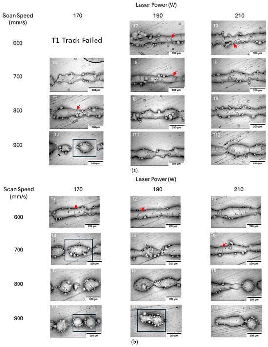
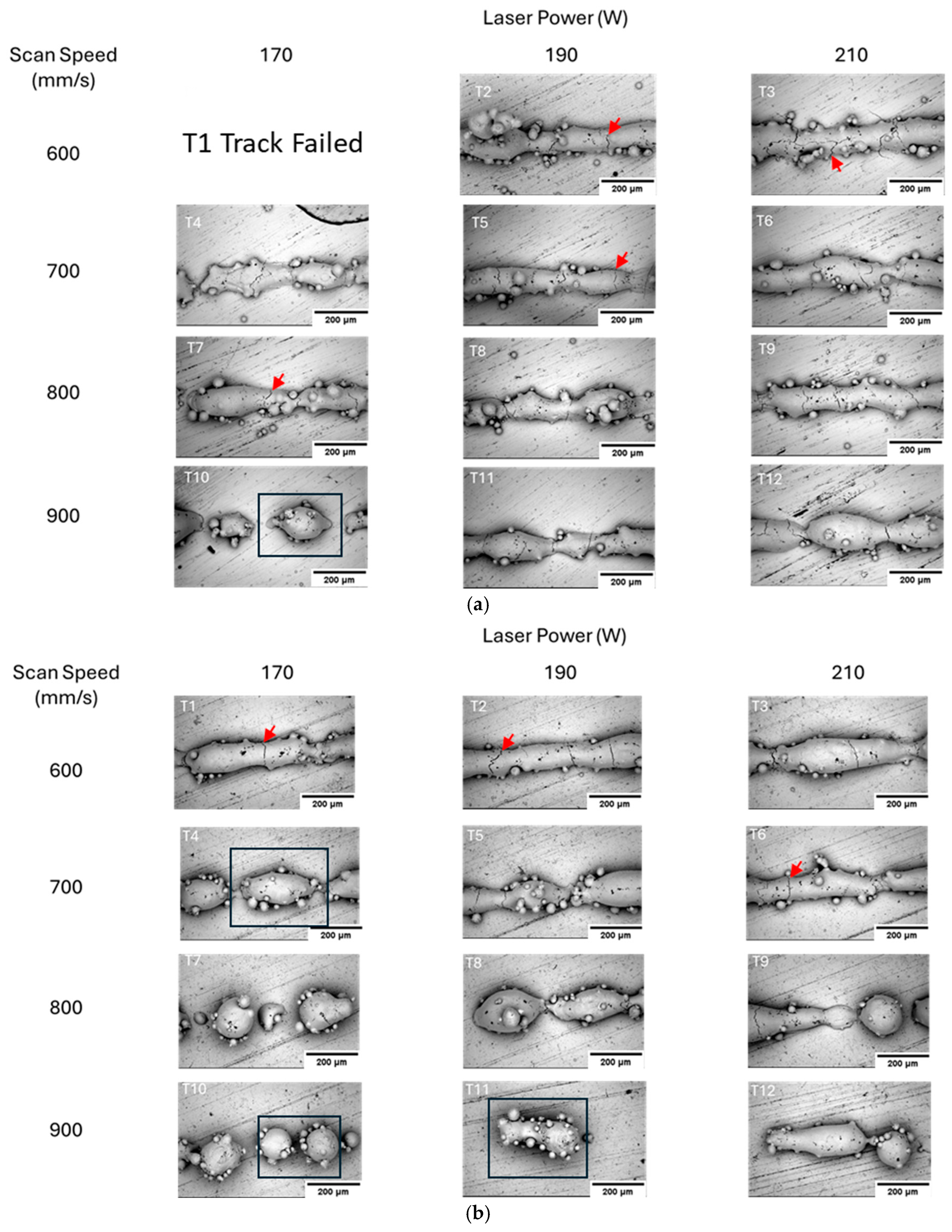
Single scan tracks were generated using AlNiCo5 powder on both the as-cast and finished AlNiCo5 substrates at varying laser powers (170–210 W) and scan speeds (600–900 mm/s). Irregularities such as balling, cracking, and discontinuities were observed across the full range of parameters, as shown in Figure 6.
Figure 6.
SEM micrographs showing top view of twelve tracks processed with AlNiCo5 powder on the (a) as-cast and (b) finished AlNiCo5 substrates. Track T1 failed as it did not consolidate on the substrate. Red arrows indicate cracks and balling phenomenon, and discontinuities are squared. The scalebar on all images is 200 μm.
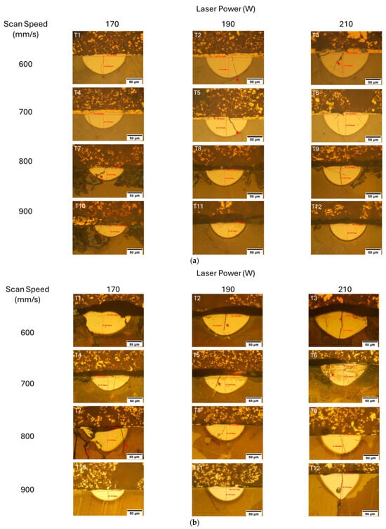
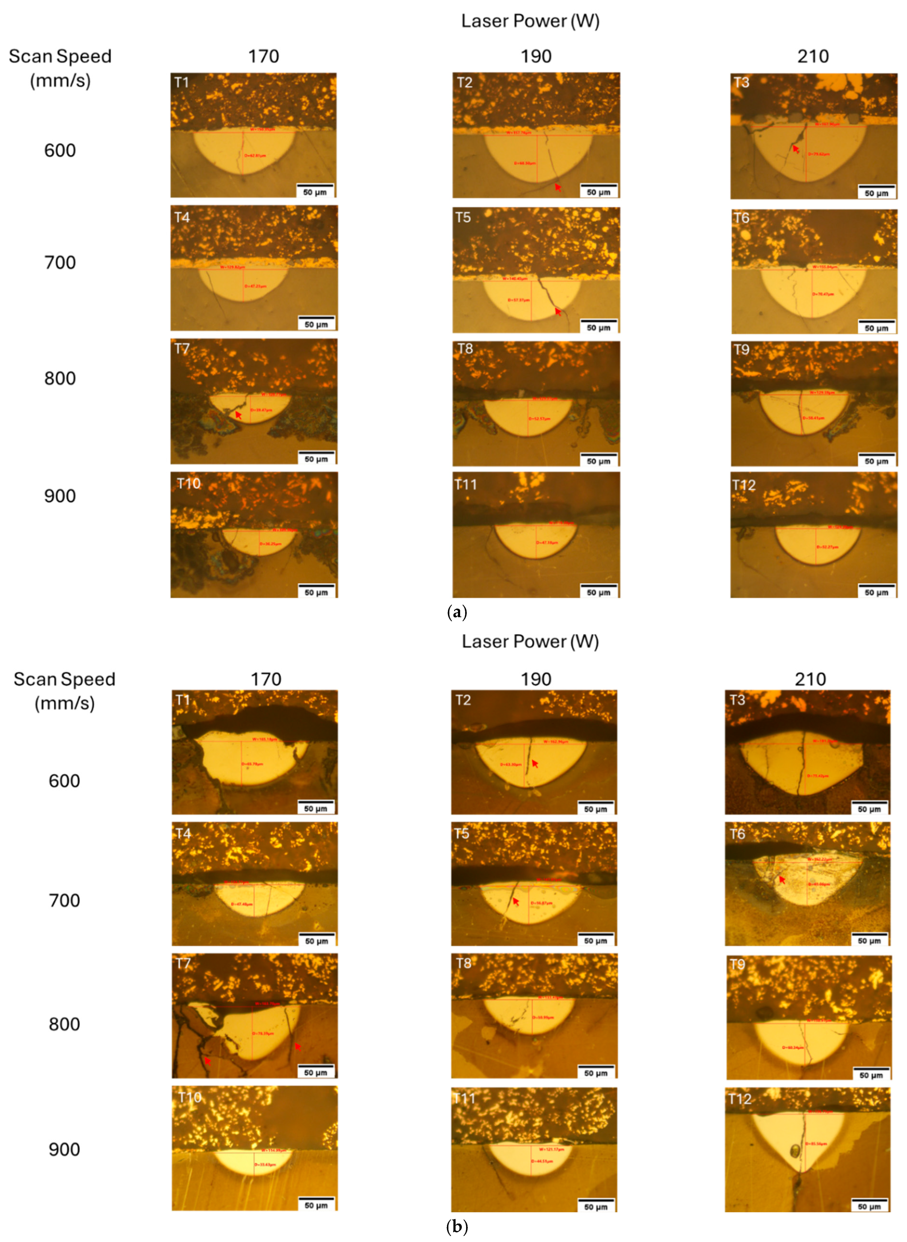
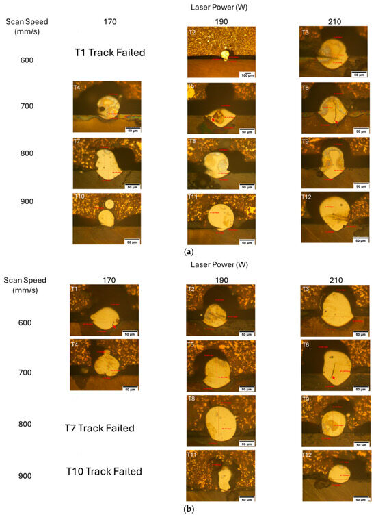
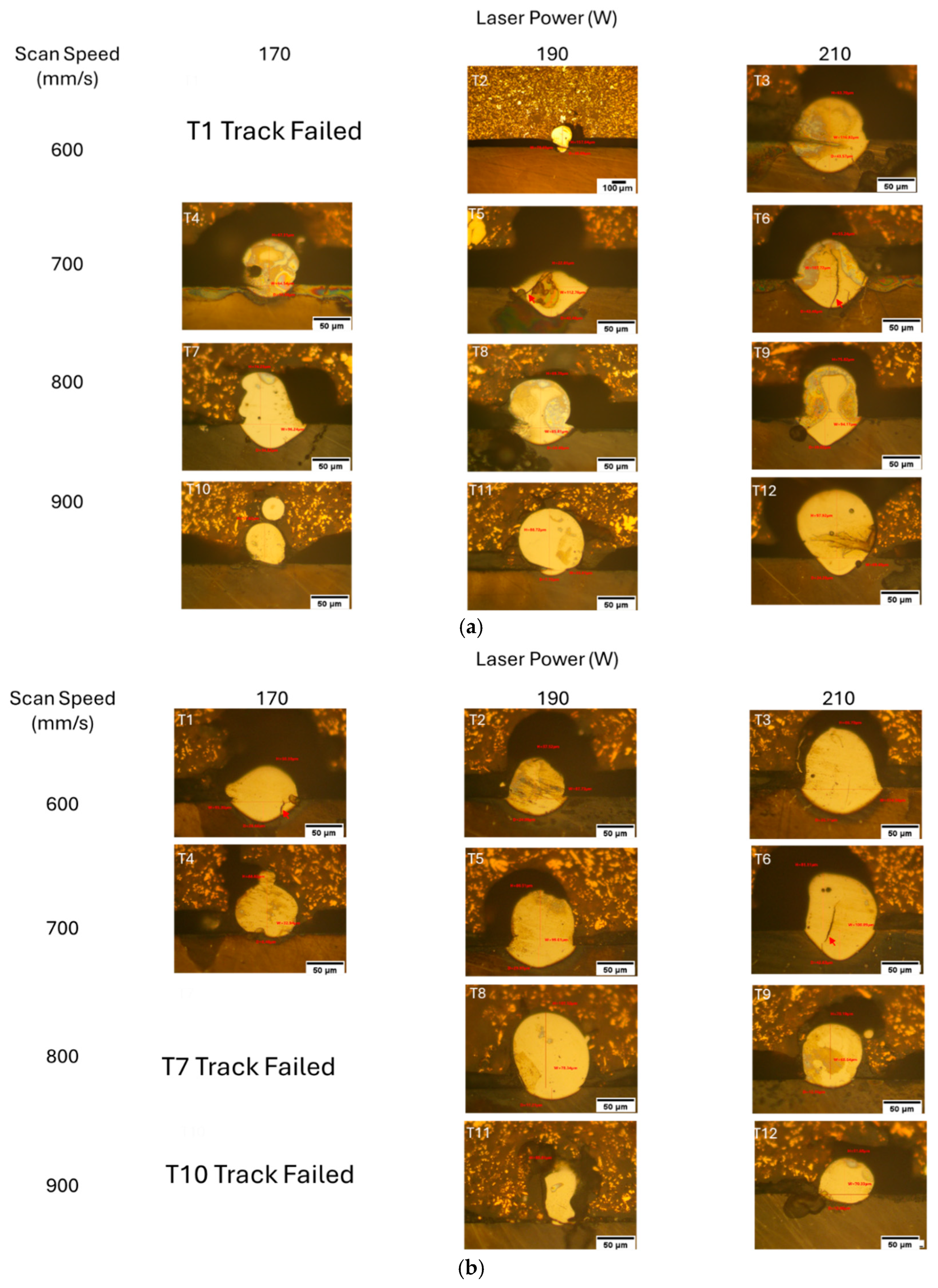
Track T1 could not be formed at 170 W and 600 mm/s on the as-cast substrate due to improper laser positioning (Figure 6). Cracks were predominantly observed transverse to the scan direction, and discontinuities, when present, were marked by separation between segments of the track. Cross-sectional optical micrographs (Figure 7) revealed variable melt pool geometries across different parameter combinations. At 170 W, the melt pools were shallow and irregular. At 190 W and 210 W, deeper and more symmetric melt pools were recorded. Track failures were noted for T7 and T10 on the finished substrate, corresponding to 800 mm/s and 900 mm/s at 170 W, respectively. Cracks were observed in several cross-sections, indicated by red arrows. The melt pool width and depth varied with both scan speed and laser power, and the measured dimensions are annotated in the images.
Figure 7.
Optical micrographs showing the cross-sectioned single tracks on bare AlNiCo5 substrates, (a) as-cast and (b) finished substrates with AlNiCo5 powder. The respective melt pools are presented with the dimensions (width and depth) measured for all process parameter sets. Red arrows indicate cracks. The scalebar on all images is 50 μm.
3.4. Melt Pool Analysis Depth-to-Width Ratio (D/W) for AlNiCo5 Substrate
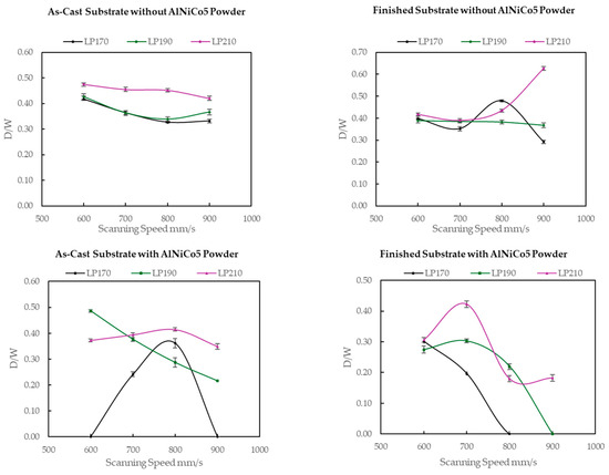
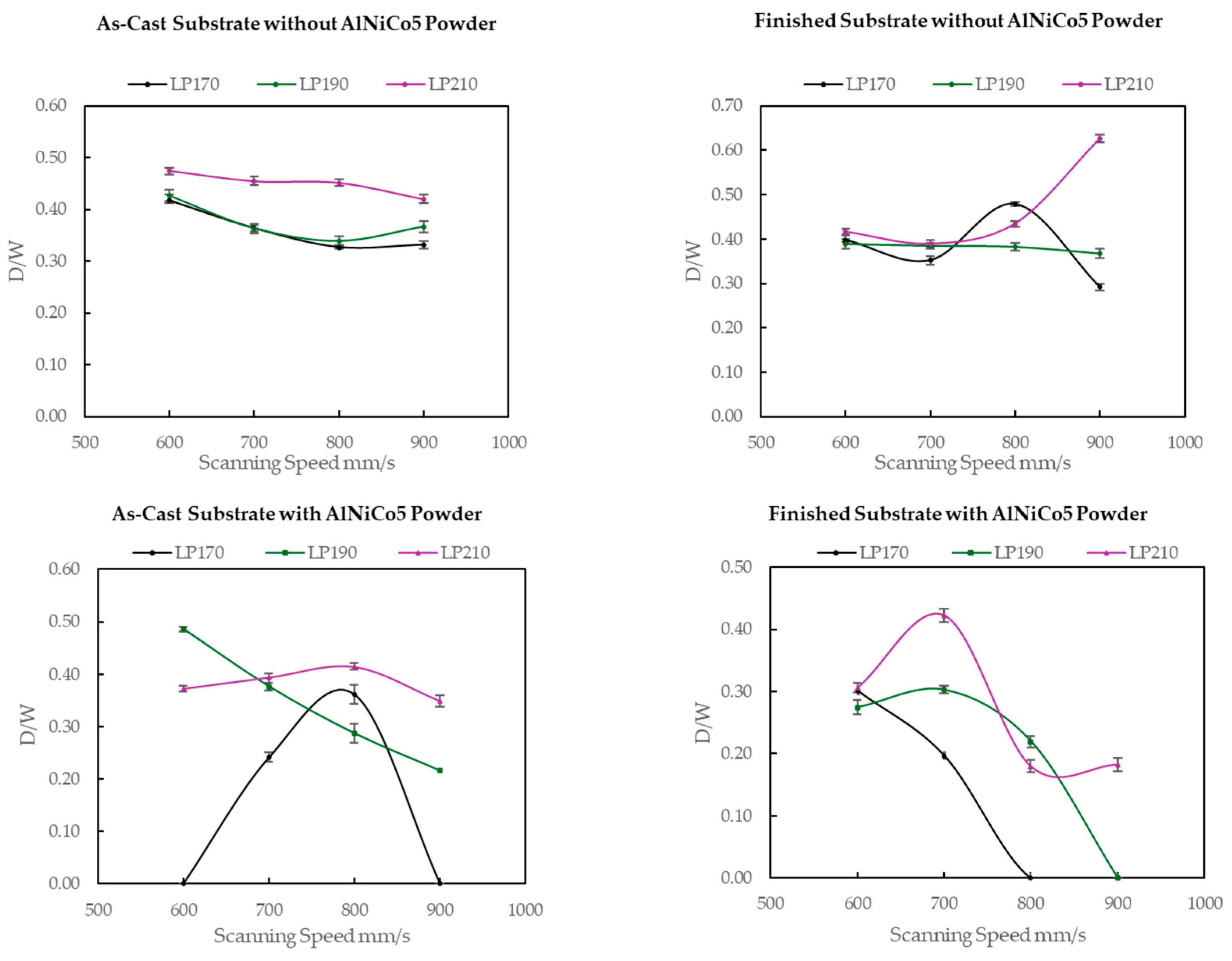
The depth-to-width ratios (D/W) of the melt pools on the AlNiCo5 substrates with and without powder are represented in Figure 8 as a function of scan speed for the utilized laser powers (170–210 W).
Figure 8.
D/W ratio of the melt pools as a function of scan speed for 170 W, 190 W, and 210 W laser power on the as-cast and finished AlNiCo5 substrates with and without AlNiCo5 powder.
3.5. Single Scan Tracks with AlNiCo5 Powder (304 Stainless Steel Substrate)
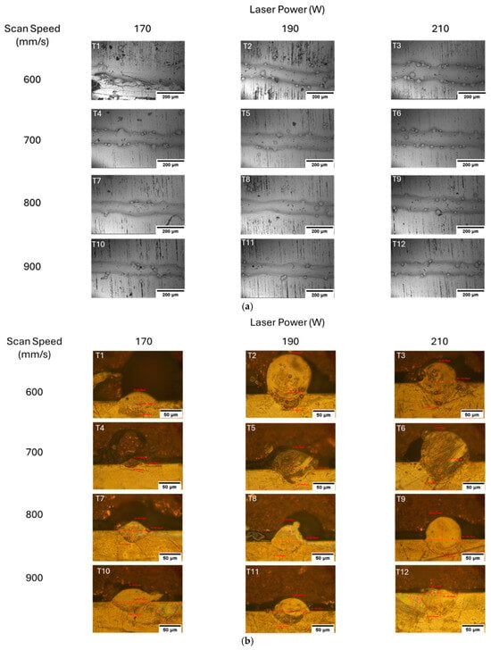
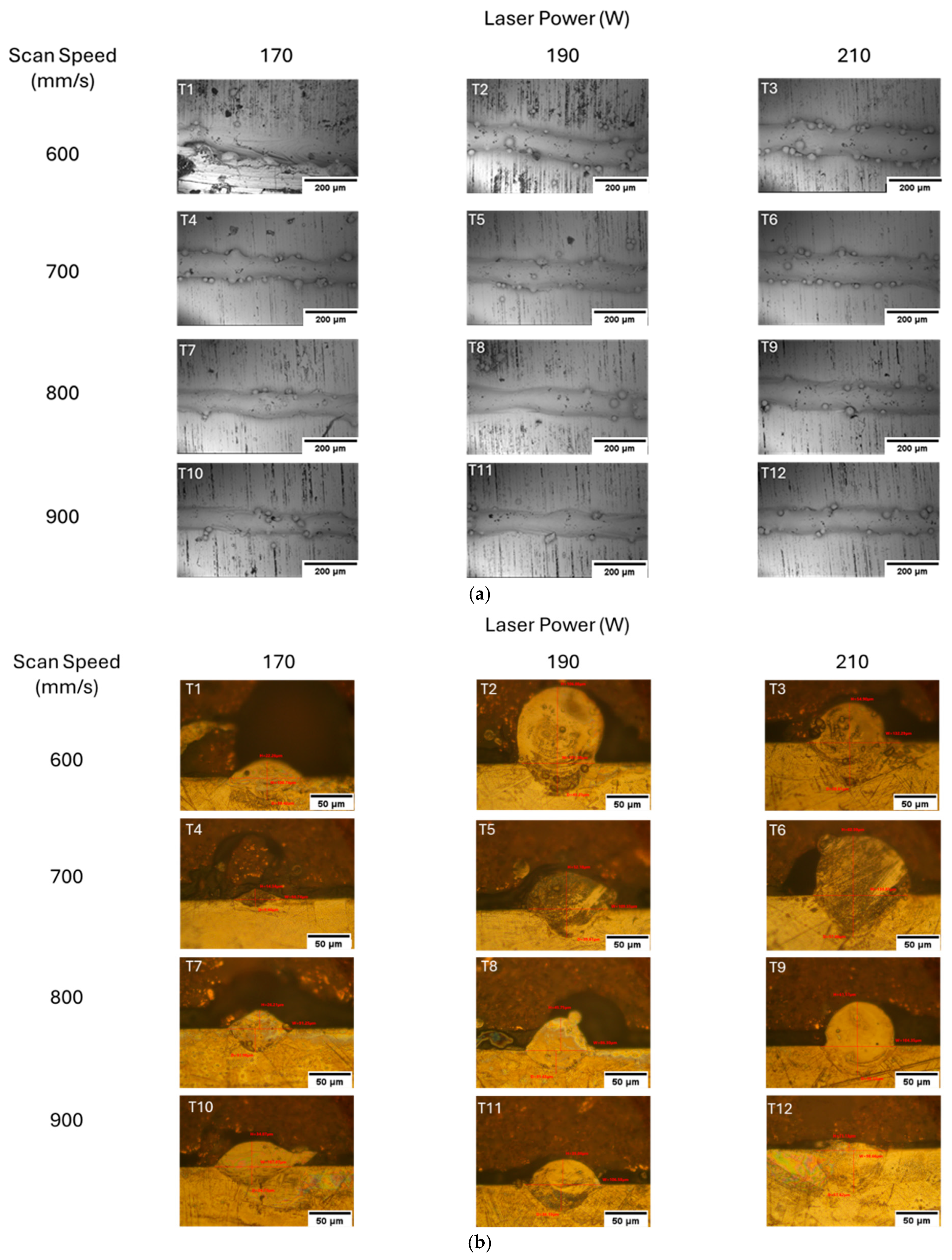
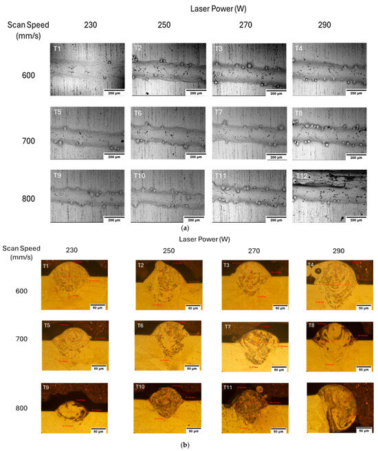
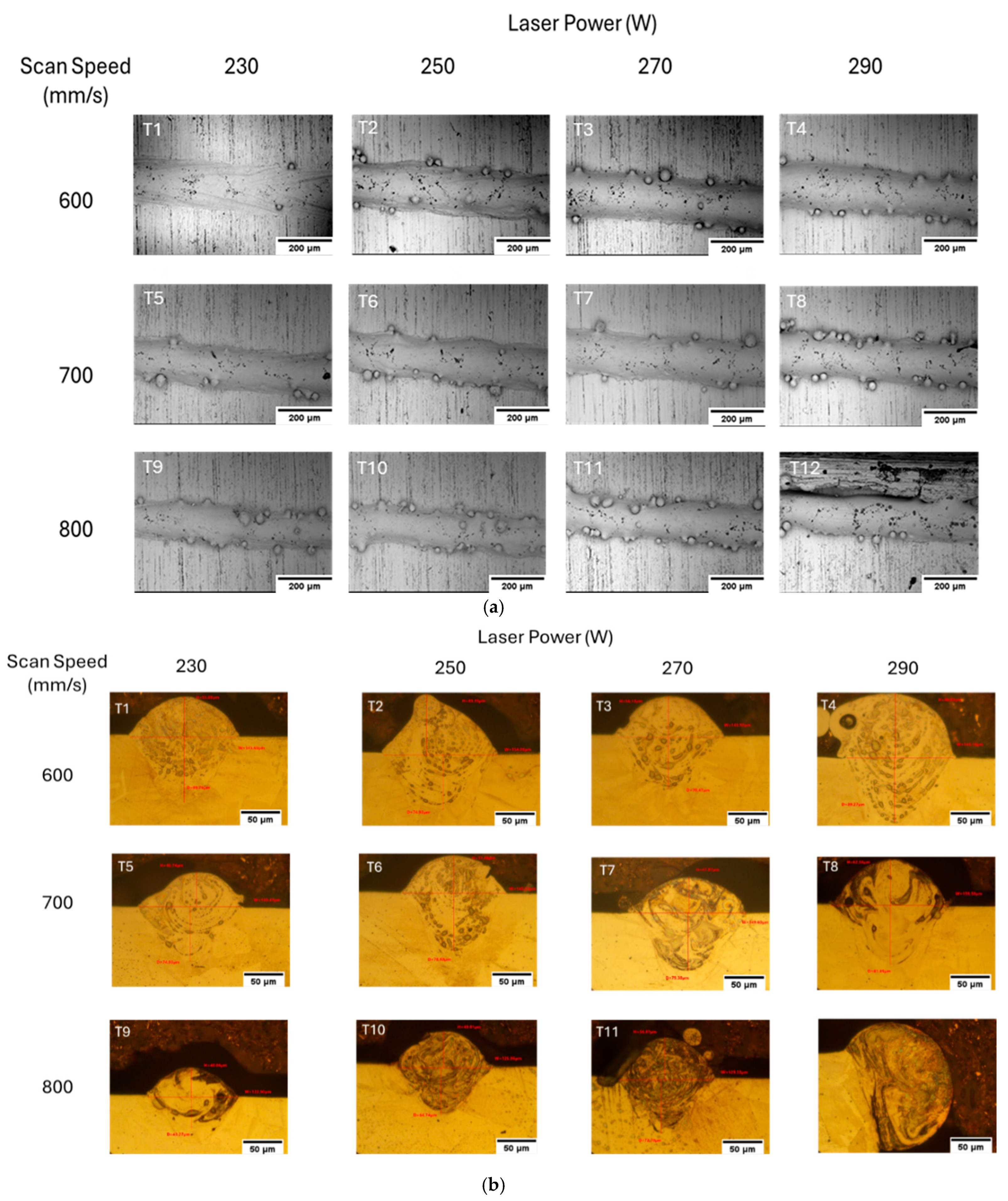
Figure 9 presents top-view SEM images and cross-sectional optical microscopy (OM) images of single tracks formed by AlNiCo5 powder deposited on the SS 304 substrates, processed with laser powers ranging from 190 to 210 W and scan speeds between 600 and 900 mm/s. Figure 10 shows corresponding SEM and OM images of single tracks produced under higher laser powers (230–290 W) and scan speeds between 600 and 800 mm/s.
Figure 9.
(a) SEM micrographs showing top view of twelve tracks processed AlNiCo5 powder on the SS 304 substrate with 190–210 W laser powers and 600–900 mm/s scan speeds, and (b) optical micrographs showing the cross-sectioned single tracks with their respective dimensions. The scalebar on all images is 50 μm.
Figure 10.
(a) SEM micrographs showing top view of twelve tracks processed AlNiCo5 powder on the SS 304 substrate with 230–290 W laser powers and 600–800 mm/s scan speeds, and (b) optical micrographs showing the cross-sectioned single tracks with their respective dimensions. The scalebar on all images is 50 μm.
3.6. Melt Pool Analysis Depth-to-Width Ratio (D/W) for 304 Stainless Steel Substrate
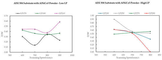
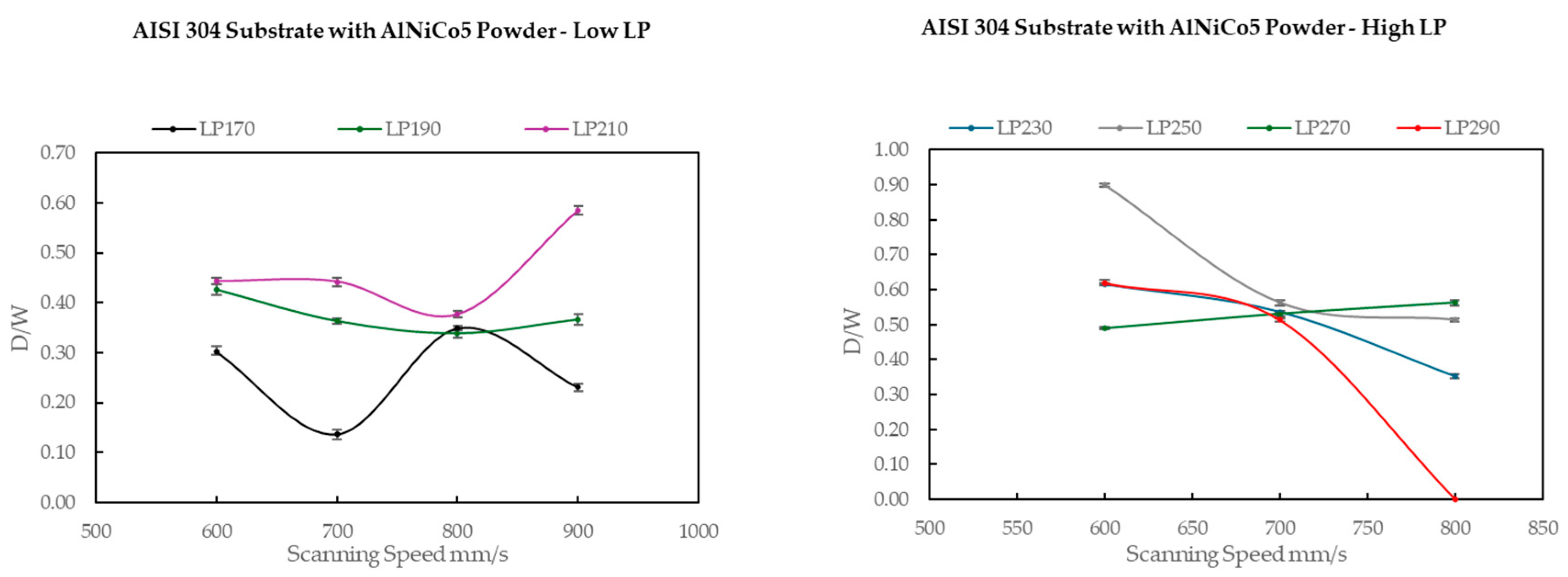
Figure 11 shows the comparison of the D/W ratio of melt pools formed on the SS 304 substrates with AlNiCo5 powder.
Figure 11.
Comparison of the D/W ratio of melt pools formed on the SS 304 substrates with AlNiCo5 powder at low (170–210 W) and high (230–290 W) laser power, as a function of scan speed.
3.7. Micro/Nanohardness of Melt Pools
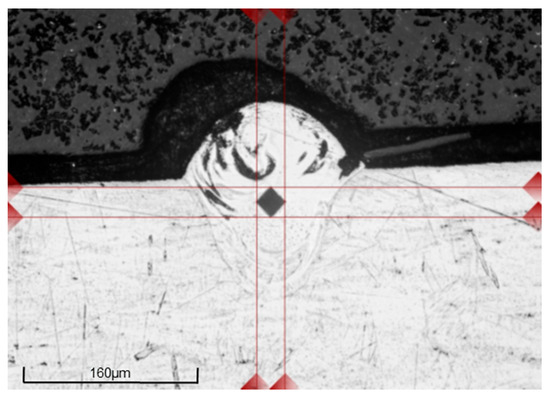
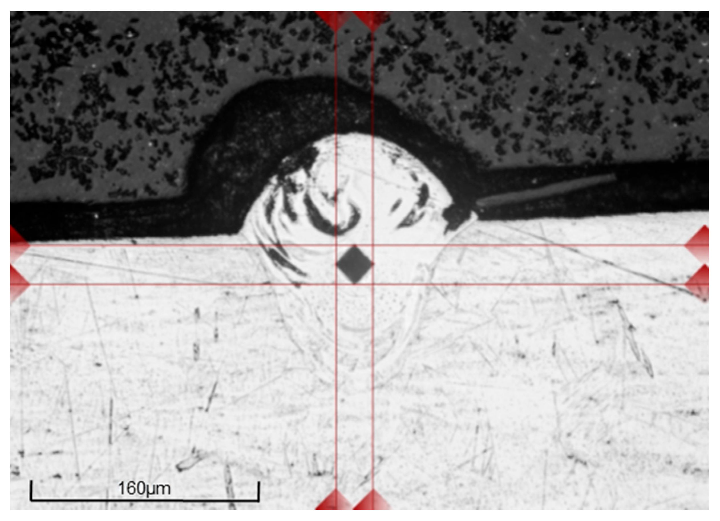
Microhardness testing was conducted on the melt pools of the tracks formed on both the AlNiCo5 and SS 304 substrates, specifically in melt pools where no cracks or other defects were observed (Figure 12). Track 5 from each substrate, with process parameters of 190 W and 700 mm/s, was selected to enable a direct comparison of hardness between the substrate materials under the same processing conditions. Additionally, Track 6 (250 W, 700 mm/s) on the SS 304 substrate was included to evaluate the effect of increased laser power at constant scan speed on the resulting track hardness. The microhardness values for each selected track, along with the corresponding substrate hardness, are summarized in Table 6.
Figure 12.
Representative microhardness indentation 0.1 HV on AlNiCo5 Track 6 formed on the 304 stainless steel substrate with 250 W laser power and 700 mm/s scanning speed.
Table 6.
Summarized Vickers hardness indentation results for the AlNiCo5 and 304 substrates and for the respective single tracks.
The microhardness of the AlNiCo5 substrates was similar. The SS 304 stainless steel substrate was softer (162 HV0.1). The single-track experiment performed at 190 W and 700 mm/s revealed a noticeable difference in microhardness between the melt pools of the as-cast and finished AlNiCo5 substrates. The track deposited on the finished substrate exhibited a higher microhardness (529 ± 5 HV) compared to the as-cast condition (484 ± 7 HV). When AlNiCo5 powder was deposited on the SS 304 substrate using the same processing parameters (190 W, 700 mm/s), the resulting single-track exhibited a hardness of 493 ± 3 HV. This value lies between the hardness values observed on the as-cast AlNiCo5 and the finished AlNiCo5 substrates. At a higher laser power of 250 W, the microhardness of the single track deposited on the SS 304 substrate decreased significantly to 260 ± 5 HV, despite maintaining the scan speed at 700 mm/s. The reduced hardness value indicates that SS 304 has diluted into the melt pool, leading to melt pool softening.
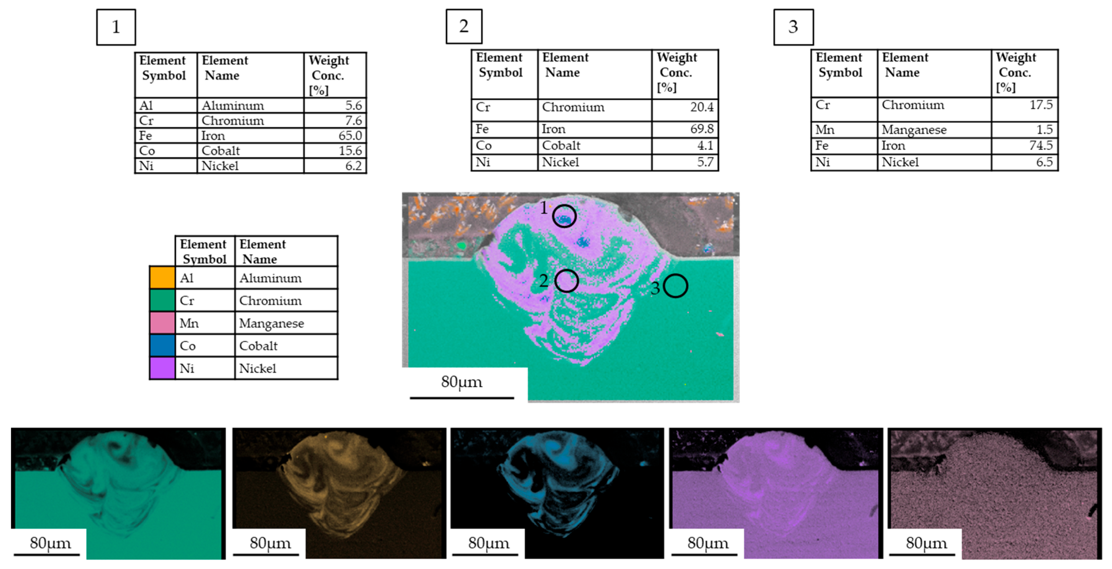
EDS elemental mapping confirmed the dilution of SS 304 stainless steel into the melt pool of Track 6 (250 W and 700 mm/s). The EDS elemental mapping on the melt pool, as well as EDS spot analysis locally within and around (SS 304 substrate) the melt pool, is illustrated in Figure 13. Iron was excluded from the elemental mapping to better visualize the distribution of the other elements, as both AlNiCo5 and SS 304 are iron-based alloys with iron concentrations exceeding 50 wt.%. Including iron would overshadow the presence and distribution of the remaining elements due to its dominant concentration. The chromium of SS 304 stainless steel penetrated the melt pool, significantly altering its chemical composition. Furthermore, the AlNiCo5 elements, such as cobalt, nickel, and aluminum, are concentrated at the same regions within the melt pool. Copper was not identified through this analysis because its concentration is quite low in AlNiCo5 powder. The local EDS spot analysis showed and validated quantitatively the variations in the chemical composition within the melt pool.
Figure 13.
Elemental distribution and local chemical composition within and around the melt pool of Track 6, formed on the SS 304 substrate using 270 W laser power and 700 mm/s scan speed. Dashed arrows indicate the points were measured with EDS spot analysis.
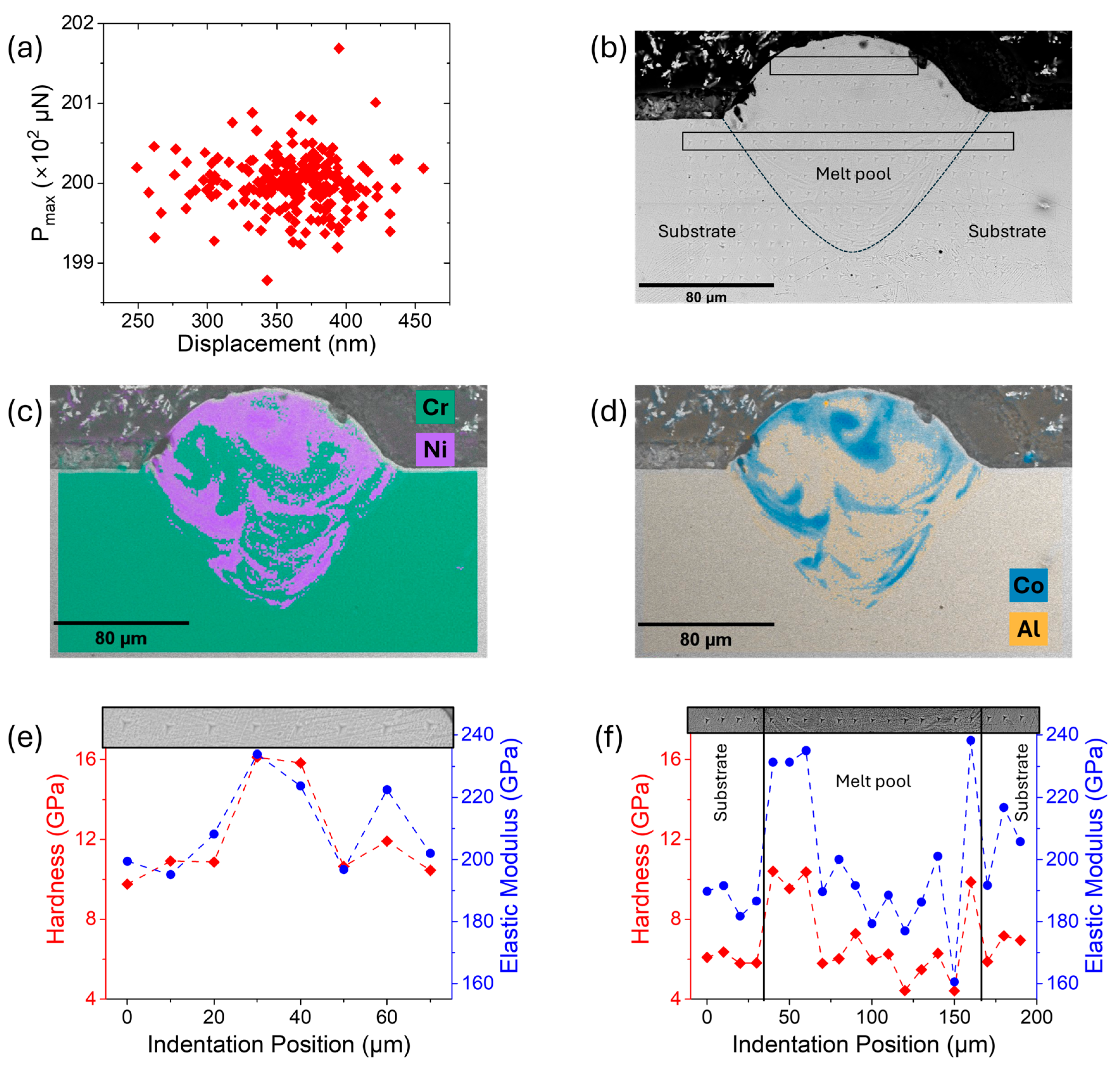
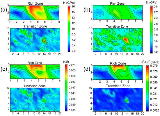
To complement the microhardness testing, nanoindentation was performed on Track 6 to gain high-resolution insight into the localized mechanical behavior of the LPBF-fabricated AlNiCo5 track and substrate system. As shown in Figure 14a, the relationship between the maximum indentation load (Pmax) and contact depth revealed a notable scatter, despite maintaining a constant 200 μN load. This dispersion indicates the microscale heterogeneity in the track and the substrate, arising from local stiffness due to elemental segregation within the melt pool, as well as from the indents placed across the SS 304 substrate (Figure 14b). To further investigate the interplay between composition and mechanical response, Figure 14e focuses on a representative linear indentation path (longitudinally) within the AlNiCo5-rich zone at the top of the track. In this region, the hardness values were consistently higher than those in the transition zone (Figure 14f), with distinct peaks at Co-rich regions, as confirmed by EDS analysis (Figure 14d).
Figure 14.
(a) Maximum indentation load as a function of contact depth for the AlNiCo5 single track. (b) SEM image of the nanoindentation imprints along the AlNiCo5 melt pool and substrate. (c,d) EDS elemental maps of the AlNiCo5 single track with green, magenta, orange, and blue colors corresponding to Cr, Ni, Al, and Co elements, respectively. Hardness (red diamonds) and elastic modulus (blue squares) of a function of contact depth for representative (e) AlNiCo5-rich and (f) transition zones. The insets show the corresponding representative indentation paths.
These spatial correlations are further depicted by the nanohardness contour map over the broader AlNiCo5-rich area, which revealed a marked heterogeneity (Figure 15a). Localized hardness maxima correspond to Co-enriched domains, while regions with increased Cr content showed systematically lower hardness (Figure 14c). This trend suggests that Cr segregation and Co absence introduce a softening effect, highlighting the sensitivity of hardness to microchemical variations within the track [41].
Figure 15.
Spatial contour plots of (a) hardness, (b) elastic modulus, (c) H/Er, and (d) H3/Er2 for the AlNiCo5-rich zone (upper) and transition zone (lower). To ease the comparison, the range of the scale bars is the same for each map.
On the contrary, the mechanical response across the transition zone displayed less pronounced variability (Figure 14f and Figure 15a,b). Along the representative indentation path shown in Figure 14f, the hardness and elastic modulus were initially low within the SS 304 substrate and increased as the path progressed into the melt pool. This behavior is in line with the rise in Co and Ni concentrations (Figure 14c,d). However, deeper into the melt pool, the hardness decreased toward substrate levels, with occasional regions showing locally elevated values attributed to Co enrichment.
Overall, the broader hardness map in the transition zone appeared more spatially uniform but with a lower hardness profile compared to the AlNiCo5-rich zone (Figure 15a). Meanwhile, some discrete regions still exhibited elevated hardness, again associated with Co enrichment, suggesting that while this region exhibits less severe compositional segregation, residual heterogeneities still influence the local mechanical response.
The elastic modulus followed a similar trend to the hardness, varying systematically across the representative indentation path (Figure 14f). However, despite evident chemical variations across the two studied regions of the track, the elastic modulus remained within a relatively narrow range of 170–230 GPa. The slight homogeneity in the elastic modulus is further supported by the spatial contour plots (Figure 15b), which show a relatively uniform distribution across both the AlNiCo5-rich and transition zones, in contrast to the more heterogeneous hardness maps (Figure 15a).
Aside from the hardness and elastic modulus, the H/Er ratio was analyzed to assess the elastic strain to failure of the material (commonly reported as resistance to wear) [42]. As shown in Figure 15c, the AlNiCo5-rich zone exhibited heterogeneous and notably elevated H/Er values, particularly in areas associated with Co enrichment. These regions correspond to zones with enhanced resistance to irreversible deformation, indicating that the material can undergo greater elastic strain before yielding. Since the elastic modulus in these regions remained relatively stable, the variations in H/Er are attributed primarily to hardness fluctuations. These higher H/Er ratios are indicative of improved elastic resilience and limited plasticity [43]. In contrast, the transition zone displayed comparatively lower and more spatially uniform H/Er values, suggesting a more plastically dominated response.
The H3/Er2 ratio (Tresca yield criterion) was also calculated to evaluate the material’s resistance to plastic deformation [42]. In the AlNiCo5-rich zone, a highly localized distribution of this ratio was observed, as shown in Figure 15d. Particularly, at specific indents where mainly cobalt and aluminum enrichment was confirmed by EDS mapping, the H3/Er2 values were notably increased, suggesting an increased resistance to plastic deformation after yielding begins. However, in neighboring areas where Co is absent or significantly lower, the ratio dropped sharply. This sensitivity emphasizes the localized mechanical advantage resulting from Co enrichment. On the other hand, the mechanical response in the transition zone exhibited a more homogenous and overall lower H3/Er2 ratio.
4. Discussion
4.1. Cracking Mechanism
To date, the effects of processing regimes on crack formation have not been sufficiently explored. During laser powder bed fusion (LPBF), cracking mechanisms, such as hot tearing (hot cracking) and cold cracking, are critical issues that can compromise the structural integrity of fabricated components. Hot tearing typically occurs during the final stages of solidification when residual stresses, generated by rapid thermal gradients, exceed the material’s tensile strength at elevated temperatures. This leads to the formation of intergranular cracks, often along grain boundaries, especially in alloys with low ductility or significant elemental segregation. The presence of a liquid film at grain boundaries, insufficient feeding of the interdendritic liquid, and high cooling rates exacerbate hot tearing susceptibility [44]. Hot tears usually form at high-angle grain boundaries and are associated with micron-sized gas pores as well as intermetallic phases in samples [45]. In contrast, cold cracking develops after solidification, primarily due to the accumulation of residual stresses from rapid cooling and cyclic thermal loading inherent to LPBF. These stresses can cause cracks to propagate through the solidified material, particularly in alloys with high hardness or brittle microstructural features, such as coarse precipitates or impurity segregation. Both mechanisms are influenced by alloy composition, process parameters, and microstructural evolution, underscoring the importance of careful material and process design to mitigate cracking during LPBF [46,47].
LPBF cracks are divided into longitudinal and transverse cracks, and they can form fracture networks in three-dimensional (3D) space [48]. Thermal stresses resulting from high cooling rates and steep thermal gradients are the main cause of crack formation in LPBF. This cracking usually occurs in the final stages of solidification (solidification cracking) when the material is partially solid and lacks sufficient liquid flow to relieve thermal stresses caused by shrinkage. Smooth-surfaced cracks and the presence of cavities or pores in the semi-solid zone can initiate these failures. The solidification gradient, which relates temperature to the fraction of solid material, is a critical factor. Lower gradients improve resistance to cracking. While these concepts have been used in welding, they need further validation for AM, particularly given the high cooling rates in LPBF [43]. In other studies, authors have also evaluated thermal stress and residual stress through experiments and simulations using various methodologies, such as the hole-drilling, contour, and neutron diffraction methods [49]. Typically, a material will deform plastically once the external stress exceeds its elastic threshold. Due to the disordered BCC (α1) and brittle ordered BCC-B2 (α2) phases [2], it is quite difficult for AlNiCo5 to dissipate residual stresses created during LPBF, presenting several dislocations generated in the microstructure. Thus, the majority of heat stress is alleviated predominantly through crack development rather than dislocation motion and plastic deformation, resulting in crack formation of AlNiCo5 during LPBF.
There is no clear distinction in the primary cracking mechanism (solidification cracking or cold cracking after solidification) of AlNiCo5 processed through LPBF. The cracking in AlNiCo5 during LPBF may be primarily driven by a combination of solidification cracking and solid-state (cold) cracking mechanisms. The majority of hot cracks (solidification cracks) initiate during the final stages of melt pool solidification, especially along grain boundaries with chemical segregation or weak bonding. These can then propagate as cold cracks into the substrate or within the melt pool due to accumulated residual stresses, since AlNiCo5 alloy lacks sufficient plasticity to dissipate these stresses through deformation. In all cases, long straight cracks along the scanning direction were observed with branching (transverse) cracks extending throughout the length of single tracks.
The samples exhibit a high density of cracks due to the extremely rapid cooling and associated high strain rates, which promote cold crack propagation and reduce the fracture toughness of AlNiCo5. Despite technological advancements (and corresponding controls on laser parameters), identifying effective solutions for accurately predicting densification and reducing crack formation in hard magnetic alloys during LPBF is an emerging field of research. Hot cracking continues to be a key issue in metallic material casting, welding, and additive manufacturing. Hot cracking occurs during metal solidification, when parts of the alloy are simultaneously in liquid and solid states. Although numerous theories and methods have been proposed to assess the susceptibility of different alloys to this defect, no single approach provides universally reliable predictions across all alloys and processing conditions. This persistent challenge highlights the need for continued research, as improved understanding and prevention of hot cracking are essential for ensuring the structural integrity and safety of metal components in industries such as aerospace and construction.
4.2. Morphological Characteristics and Melting Modes of Single Tracks
The single tracks formed on AlNiCo5 substrates without powder resulted in extensive cracking (Figure 4 and Figure 5). When AlNiCo5 powder is used for the formation of single tracks, irregularities and discontinuities are evident for the whole range of scan speeds employed (Figure 6). Track 4, Track 10, and Track 11 featured excessive balling, as shown in Figure 6b for the finished AlNiCo5 substrate. Balling is the disruption of melt pool continuity, where the molten material forms separate spherical droplets instead of a uniform track [50]. However, a more stable regime seems to be achieved when laser power is set at 210 W with balling being reduced, especially for scan speeds below 700 mm/s. It must be noted that the single scan tracks that were formed from AlNiCo5 powder on AlNiCo5 substrates featured cracks only in the transverse direction to that of the scanning direction. Longitudinal cracks parallel to the scanning direction were absent, and this might be attributed to the discontinuities of the tracks. Partially melted or unfused particles could be seen adjacent to the single tracks; however, there was a lack of a denudation zone immediately surrounding the solidified tracks. Track 1 on the as-cast AlNiCo5 substrate could not be formed during the process because the laser scanning was too close to the edge of the rectangular substrate (Figure 6a and Figure 7a). The optical images in Figure 7 reveal the melt pool’s shape and size. It is evident that cracks and dimensionally asymmetric and shallow melt pools were observed both in the as-cast and finished substrates. Melt pool cross-sections could not be illustrated for Track 1 (as-cast substrate), due to incomplete track formation, or for Tracks 7 and 10 (finished substrate), due to the presence of pronounced discontinuities and balling effects. The tracks affected by balling demonstrated increased melt pool heights, likely resulting from inadequate fusion and limited penetration into the substrate material.
The D/W ratio of the melt pool is a key indicator of the melting mode. Ratios below 0.5 indicate conduction mode, values ≥ 0.8 correspond to keyhole mode, and intermediate values (0.5–0.8) represent transition mode [51]. Transition mode is preferred in LPBF as it combines the stable geometry of conduction mode with the penetration depth of keyhole mode. Overall, the melting regime is more stable for the tracks with no powder, as there are smaller deviations in the D/W ratio (Figure 8). When single-track experiments are conducted without powder (i.e., on bare substrates), they typically result in more stable and consistent melt pools, as the laser interacts directly with a solid surface, reducing variability introduced by powder morphology, packing density, and flowability. On the other hand, when using a powder layer, the melt pool behavior becomes less stable due to the heterogeneous nature of the powder bed, but track widths and heights tend to be larger. This is attributed to the higher absorptivity of powder, as multiple scattering among powder particles increases the effective absorption of laser energy [52]. When increasing the scan speed, the D/W ratio decreased (smaller-sized melt pools) in the case of the single tracks on the AlNiCo5 substrates without AlNiCo5 powder. Studies on LPBF single-track experiments have shown that increasing the scan speed, while keeping the laser power constant, leads to a reduction in melt volume due to the lower energy density delivered to the material [53]. In contrast, the trend of size reduction with increasing scan speed is not that evident in the case of single tracks with AlNiCo5 powder. Notably, on the as-cast substrate coated with AlNiCo5 powder, the tracks with 210 W laser power showed stable D/W values (0.35–0.41) across 600–900 mm/s scan speeds, indicating consistent melting. The track with 170 W laser power exhibited the maximum D/W at 800 mm/s, while the D/W of the tracks with 190 W laser power gradually decreased from 0.49 to 0.22 with increasing scan speed. On the finished substrate coated with AlNiCo5 powder, the tracks with 210 W laser power reached a maximum D/W (0.42) at 700 mm/s, reflecting efficient melting at intermediate scan speeds. In contrast, the tracks with 170 W and 190 W laser powers showed decreasing D/W ratios with increasing scan speed, suggesting reduced melt pool penetration. The as-cast substrate demonstrated a more stable processing regime compared to the finished magnet. Both AlNiCo5 substrates coated with AlNiCo5 powder exhibited a highly stable melting regime at ≥190 W laser power and scan speeds of 600 and 700 mm/s (e.g., Tracks 2, 3, 5, and 6 on both AlNiCo5 substrates). Among all these tracks, only single Track 2 on the as-cast substrate, with a D/W ratio of 0.49, approached the range of the transition melting mode. In the case of single tracks fabricated on bare substrates (without AlNiCo5 powder), Tracks 1–11 exhibited D/W ratios below 0.5, indicative of a conduction melting mode. In contrast, Track 12, with a D/W ratio of 0.63, clearly fell within the transition melting mode range. Overall, the majority of the fabricated tracks on the AlNiCo5 substrates, both with and without the presence of AlNiCo5 powder, exhibited a conduction melting mode when processed with laser powers ranging from 170 to 210 W and scan speeds between 600 and 900 mm/s.
Replacing the AlNiCo5 substrate with SS 304 stainless steel (Figure 9 and Figure 10) eliminated the cracks on the single tracks even when applying higher laser powers (230–290 W). The use of the SS 304 stainless steel substrate offers a significant advantage in mitigating cracking during the LPBF processing of AlNiCo5 powder. SS 304 stainless steel is frequently used in both fusion welding and additive manufacturing with iron-based alloys due to its excellent weldability [54,55]. AlNiCo5 can be considered an iron-based alloy since its weight concentration reaches up to approximately 50%. The FCC crystal structure of SS 304 stainless steel imparts high ductility, which enables the substrate to effectively accommodate the thermal stresses induced during the rapid heating and cooling cycles of single-track formation [56]. Additionally, stable and continuous tracks without disruptions and balling phenomena were formed on the SS 304 substrate. The single tracks on the SS 304 substrate exhibited stable melt pools with dimensionally symmetric bead morphology. The higher laser power contributed to the formation of wider and deeper melt pools, ensuring better adhesion between the single tracks and the substrate. No melt pool dimensions were obtained for Track 12 from the high laser power single-track experiments on the SS 304 stainless steel substrate because it was near the edge of the rectangular substrate.
Two conflicting effects influence track height. After laser radiation, the liquid produced can spill over to two sides, capturing neighboring powder particles and dragging them into the molten pool, therefore creating a denudation zone [14]. The denudation zone was reported to grow with laser power [57,58]. Therefore, higher absorbed energy enhances the molten pool’s capacity to incorporate powder particles, leading to a track taller than the initial powder layer. On the other hand, the fluid flow driving forces get stronger and the lifetime of the molten pool extends, causing the molten pool to expand, resulting in a reduced height. As a result, variations in laser power or scan speed do not produce a predictable trend in track height because of these opposing effects.
The tracks with 190 and 210 W laser powers exhibited stable D/W ratios at scan speeds of 600–700 mm/s. Specifically, the tracks with laser powers of 190 W and across all scan speeds (600–900 mm/s) showed the most stable melting regime compared to all tracks fabricated in the SS 304 substrate with 170–210 W laser powers. These were Tracks 2, 3, 5, 6, 8, and 11, resulting in a D/W ratio < 0.50, with Tracks 3 and 6 approaching transition melting mode with a 0.44 D/W ratio. Among the single-track experiments using AlNiCo5 powder on the SS 304 substrate with laser powers ranging from 170 to 210 W, only Track 12 exhibited transition melting mode, characterized by a D/W ratio of 0.58. This track showed the lowest height (Figure 9b), suggesting that an insufficient amount of powder was deposited in this region during the experiment. Consequently, the applied heat input was used to melt a smaller volume of material. The rest of the tracks fabricated on the SS 304 substrate with 170–210 W LP showed conduction melting mode. The increase in laser power values (230–290 W) resulted in increased melt pool dimensions (Figure 10b). Deeper melt pools were predominantly observed at laser powers ≥ 230 W. The melt pool depth must reach at least the selected layer thickness [51]. As shown in Figure 11, the most stable D/W ratios (0.49–0.56) were observed on the tracks with 270 W LP across all scan speeds (e.g., Tracks 3, 7, and 11 for the SS 304 substrate—high LP). Most of the tracks (8 out of 11) fabricated on the SS 304 stainless steel substrate with 230–290 W LP resulted in a D/W ratio that fell into the transition melting mode range. Specifically, Tracks 1, 4, 5, 6, 7, 8, 10, and 11 exhibited transition melting mode, Tracks 3 and 9 showed conduction melting mode, and only Track 2 resulted in a D/W ratio above 0.8, classifying it as a track with keyhole melting mode.
The fabrication of high-density components in LPBF is not only dependent on the prevailing melt pool mode but also on the appropriate selection of process parameters, particularly layer thickness and hatch distance. Thus, a wide process window, including conduction, transition, and keyhole modes, can be effective, depending on the chosen layer thickness, hatch spacing, and specific application goals. Therefore, careful optimization of process parameters in relation to melt pool geometry is essential to ensure adequate bonding between layers and to achieve the desired part quality.
4.3. Microhardness and Nanoindentation
The microhardness measurements showed that while the AlNiCo5 substrates (as-cast and finished) exhibited similar values, the SS 304 substrate was significantly softer due to its ductile FCC microstructure [59]. Notably, the melt pool’s microhardness of the single track on the finished AlNiCo5 substrate was higher compared to that on the as-cast substrate. The difference can be attributed to the microstructural and thermal history of the substrates. The finished AlNiCo5 substrate had undergone annealing and thermomagnetic treatment, resulting in a more homogeneous and transformed microstructure due to spinodal decomposition, with thermal diffusivity changing the distribution of thermal stresses during LPBF processing within the melt pool [60]. This, in turn, may have contributed to a more refined microstructure upon solidification compared to the as-cast substrate melt pool, thereby enhancing the resulting hardness. Changing the substrate to SS 304 and using the same processing parameters, the melt pool’s microhardness of the resulting single track was found to lie between the values of the tracks measured on the as-cast and finished AlNiCo5 substrates. The measured hardness suggests that, under a laser power of 170 W and scanning speed of 700 mm/s, SS 304 did not undergo significant dilution into the melt pool. Increasing the laser power to 250 W resulted in a significant decrease in the microhardness of the single track on the SS 304 substrate by nearly 50%, despite maintaining the scanning speed at 700 mm/s. This pronounced reduction in hardness may be the result of excessive heat input, which led to the over-melting of the powder and the substrate. The increased heat input can also promote coarser grain formation due to slower cooling rates and reduced thermal gradients [61]. Moreover, the increased laser power likely intensified the melting conditions, promoting greater dilution between the AlNiCo5 track and the SS 304 substrate. This may have altered the local composition, subsequently leading to a reduction in hardness. Dilution frequently occurs in laser cladding and powder-fed laser directed energy deposition technologies, where the increase in laser power has been shown to significantly raise the degree of dilution and melt pool depth [62]. EDS elemental mapping and localized spot analysis confirmed the dilution of SS 304 into the melt pool. The major elements of AlNiCo5, such as cobalt and aluminum, were concentrated mainly at the upper region of the melt pool, while chromium and the other elements from the SS 304 substrate were primarily found in the center and lower regions of the melt pool. The dilution of SS 304 into the AlNiCo5 track was more pronounced with an increase in the laser power, which is expected due to an intensified Marangoni effect and stronger capillary forces [63].
Nanoindentation testing showed that local nanohardness was affected by the inhomogeneous distribution of the alloying elements into the melt pool. Regions rich in cobalt and aluminum elements, which are major AlNiCo5 chemical elements, resulted in increased nanomechanical properties, while regions with increased concentrations of SS 304 elements exhibited reduced nanomechanical properties. This trend is consistent with the reported hardening effect of Co either through solid-solution strengthening in Ni-Co alloys or by promoting the formation of hard intermetallic phases in Al-Co alloy systems [64,65]. The observed softening within the melt pool suggests a depletion of AlNiCo5 elements, such as Co and Al, alongside a dominant presence of softer SS 304 substrate elements, particularly Cr and, to a lesser extent, Ni, through interdiffusion during solidification. This compositional shift may lead to the transformation of hard BCC phases into softer FCC. Additionally, Al promotes the formation of hard BCC phases in similar alloy systems, significantly contributing to strength through mechanisms like spinodal decomposition. Its absence can lead to the formation of softer FCC phases [66,67]. Such compositional variations and resulting mechanical heterogeneity are consistent with diffusion-driven elemental mixing during melt pool solidification. The high temperatures and increased diffusivity during LPBF processing promote significant element transport across the substrate–melt pool interface. Moreover, Marangoni convection within the molten pool redistributes elements, disrupting chemical uniformity and contributing to the spatial heterogeneity observed in hardness and modulus values [68]. These thermal and chemical effects are further intensified when using high power. Studies have demonstrated that high laser power—such as that used in this case—can lead to the vaporization of specific elements and promote chemical segregation during solidification [69]. Pei et al. reported that excessive laser energy during LPBF of Al–Si–10Mg resulted in vaporization of volatile elements, altering the chemical composition and inducing spatial variation in nanohardness across the melt pool [70]. Although based on a different alloy system, the chemical heterogeneity is a common feature in LPBF processing and aligns well with our observations [71].
5. Conclusions
In this study, the processability of the hard magnetic alloy AlNiCo5 by LPBF was investigated. Specifically, the formation of single scan tracks with and without powder on AlNiCo5 and SS 304 substrates was examined. The conclusions of this study are summarized below:
- Extensive cracking was observed in most single scan tracks on AlNiCo5 substrates, both with and without AlNiCo5 powder deposition, regardless of the process parameters. This can be attributed to a combination of brittle phases in the AlNiCo5 microstructure, high thermal stresses induced by the rapid cooling and steep thermal gradients of the LPBF process, and solidification cracking during the final stages of melt pool freezing.
- Single tracks on AlNiCo5 substrates with powder exhibited irregularities, discontinuities, and balling, with shallow and asymmetric melt pools.
- Tracks fabricated on SS 304 stainless steel substrates with powder exhibited uniform and continuous morphology, improved wettability and adhesion, and larger, crack-free melt pools. Owing to its high ductility and excellent weldability, SS 304 effectively absorbed thermal stresses during LPBF, making it the most suitable substrate for AlNiCo5 fabrication.
- Most single tracks on AlNiCo5 and SS 304 substrates exhibited conduction melting mode (D/W < 0.5), with stable melting achieved at 190 W and 600–900 mm/s in the DoE with laser powers between 170 and 210 W and scan speeds of 600–900 mm/s.
- At higher laser powers (230–290 W) in single tracks fabricated on SS 304 substrate, the melt pool dimensions increased significantly, especially at 600–700 mm/s. Most tracks exhibited transition melting mode (D/W = 0.5–0.8), a few remained in conduction mode (D/W < 0.5), and only one track showed keyhole melting (D/W > 0.8). The most stable melting in this range was observed at 270 W across all scan speeds, with D/W values of 0.49–0.56.
- The microhardness of the melt pools remained relatively consistent across different substrates when using the same processing parameters. However, increasing the laser power led to greater dilution from the SS 304 substrate into the melt pool, significantly altering its chemical composition and resulting in a significant reduction in hardness.
- Nanoindentation testing revealed significant microscale mechanical heterogeneity across the LPBF-fabricated AlNiCo5 track, strongly influenced by local compositional variations. Higher hardness, elastic modulus, H/Er ratio, and resistance to plastic deformation (H3/Er2) values were observed in Co-enriched and Al regions within the AlNiCo5-rich zone, while Cr-enriched areas and regions affected by SS 304 substrate dilution within the melt pool exhibited softening, likely due to a transition from hard BCC to soft FCC phases driven by elemental interdiffusion during solidification. Hence, careful selection of laser power is essential when depositing AlNiCo5 powder on SS 304 substrates to preserve mechanical integrity during LPBF and avoid delamination and cracks, as adhesion during the first layer of the process is crucial for successful manufacturing of hard magnetic alloys.
Author Contributions
Conceptualization, L.G., E.P.K., and E.K.K.; methodology, L.G., L.K., A.A., E.K.K., and E.P.K.; formal analysis, L.G., L.K., A.A., E.K.K., and E.P.K.; investigation, L.G., L.K., A.A., E.P.K., and E.K.K.; writing—original draft preparation, L.G. and E.K.K.; writing—review and editing, L.G., L.K., A.A., E.K.K., and E.P.K.; supervision, E.P.K. and E.K.K.; project administration, L.G. and E.P.K.; funding acquisition, E.P.K. and E.K.K. All authors have read and agreed to the published version of the manuscript.
Funding
This research was funded by the European Commission under Horizon-CL4-2023-RESILIENCE-01-37 and the European Health and Digital Executive Agency (HADEA) under Grant Agreement Project 101130095—MagNEO (Advanced additively manufactured permanent magnets for New Energy and Mobility Applications). The views and opinions expressed are, however, those of the author(s) only and do not necessarily reflect those of the European Union or HADEA. Neither the European Union nor HADEA can be held responsible for them.
Data Availability Statement
The data presented in this study are available on request from the corresponding author. The data are not publicly available due to privacy restrictions.
Acknowledgments
The authors gratefully acknowledge the contribution of N. Sargioti, from CONIFY, to the experimental design, and Ernesto Urionabarrenechea Gomez, from CEIT, for his contribution regarding the production of feedstock material (gas atomization of metal powder).
Conflicts of Interest
Authors Leonidas Gargalis, Leonidas Karavias, Evangelia K. Karaxi were employed by the company CONIFY. The remaining authors declare that the research was conducted in the absence of any commercial or financial relationships that could be construed as a potential conflict of interest.
Abbreviations
The following abbreviations are used in this manuscript:
| LPBF | Laser Powder Bed Fusion |
| SS | Stainless Steel |
| DoE | Design of Experiment |
| BHmax | Maximum Energy Product |
| Hc | Coercivity |
| Br | Remanent Magnetization/Induction |
| MGOe | Mega Oersted (unit) |
| BCC | Body-Centered Cubic |
| FCC | Face-Centered Cubic |
| SEM | Scanning Electron Microscopy |
| AM | Additive Manufacturing |
| REE | Rear Earth Elements |
| DED | Directed Energy Deposition |
| EBM | Electron Beam Melting |
| EDS | Energy-Dispersive Spectroscopy |
| PM | Permanent Magnets |
| LED | Linear Energy Density |
| PSD | Particle Size Distribution |
| OM | Optical Microscopy |
| 3D | Three-Dimensional |
References
- Cullity, B.D.; Graham, D. Introduction to Magnetic Materials; John Wiley. & Sons, Inc.: Hoboken, NJ, USA, 2009. [Google Scholar]
- Zhou, L.; Miller, M.; Lu, P.; Ke, L.; Skomski, R.; Dillon, H.; Xing, Q.; Palasyuk, A.; McCartney, M.R.; Smith, D.J.; et al. Architecture and magnetism of alnico. Acta Mater. 2014, 74, 224–233. [Google Scholar] [CrossRef] [Scilit]
- Kittel, C.; Nesbitt, E.A.; Schokley, W. Theory of Magnetic Properties and Nucleation in Alnico V. Phys. Rev. 1950, 77, 839–840. [Google Scholar] [CrossRef] [Scilit]
- Sun, Y.L.; Zhao, J.T.; Liu, Z.; Xia, W.X.; Zhu, S.M.; Lee, D.; Yan, A.R. The phase and microstructure analysis of Alnico magnets with high coercivity. J. Magn. Magn. Mater. 2015, 379, 58–62. [Google Scholar] [CrossRef] [Scilit]
- White, E.M.H.; Kassen, A.G.; Simsek, E.; Tang, W.; Ott, R.T.; Anderson, I.E. Net shape processing of AlNiCo magnets by additive manufacturing. IEEE Trans. Magn. 2017, 53, 1–6. [Google Scholar] [CrossRef] [Scilit]
- Coey, J.M.D. Perspective and prospects for rare earth permanent magnets. Engineering 2020, 6, 119–131. [Google Scholar] [CrossRef] [Scilit]
- Gutfleisch, O.; Willard, M.A.; Brück, E.; Chen, C.H.; Sankar, S.G.; Liu, J.P. Magnetic materials and devices for the 21st century: Stronger, lighter, and more energy efficient. Adv. Mater. 2011, 23, 821–842. [Google Scholar] [CrossRef] [Scilit] [PubMed]
- Wu, J.; Korman, O.; Di Nardo, M.; Degano, M.; Gerada, C.; Ashcroft, I.; Hague, R.J.M.; Aboulkhair, N.T. Additive Manufacturing of Nd-Fe-B Permanent Magnets and Their Application in Electrical Machines. IEEE Access 2024, 12, 138921–138931. [Google Scholar] [CrossRef] [Scilit]
- Wu, J.; Aboulkhair, N.T.; Degano, M.; Ashcroft, I.; Hague, R.J.M. Process-structure-property relationships in laser powder bed fusion of permanent magnetic Nd-Fe-B. Mater. Des. 2021, 209, 109992. [Google Scholar] [CrossRef] [Scilit]
- Bittner, F.; Thielsch, J.; Drossel, W.-G. Laser powder bed fusion of Nd–Fe–B permanent magnets. Prog. Addit. Manuf. 2020, 5, 3–9. [Google Scholar] [CrossRef] [Scilit]
- Bittner, F.; Thielsch, J.; Drossel, W.-G. Microstructure and magnetic properties of Nd-Fe-B permanent magnets produced by laser powder bed fusion. Scr. Mater. 2021, 201, 113921. [Google Scholar] [CrossRef] [Scilit]
- Yadroitsev, I.; Gusarov, A.; Yadroitsava, I.; Smurov, I. Single track formation in selective laser melting of metal powders. J. Mater. Process. Tech. 2010, 210, 1624–1631. [Google Scholar] [CrossRef] [Scilit]
- Yadroitsev, I.; Smurov, I. Selective laser melting technology: From the single laser melted track stability to 3D parts of complex shape. Phys. Procedia 2010, 5, 551–560. [Google Scholar] [CrossRef] [Scilit]
- Khairallah, S.A.; Anderson, A.T.; Rubenchik, A.; King, W.E. Laser powder-bed fusion additive manufacturing: Physics of complex melt flow and formation mechanisms of pores, spatter, and denudation zones. Acta Mater. 2016, 108, 36–45. [Google Scholar] [CrossRef] [Scilit]
- King, W.E.; Barth, H.D.; Castillo, V.M.; Gallegos, G.F.; Gibbs, J.W.; Hahn, D.E.; Kamath, C.; Rubenchik, A.M. Observation of keyhole-mode laser melting in laser powder-bed fusion additive manufacturing. J. Mater. Process. Tech. 2014, 214, 2915–2925. [Google Scholar] [CrossRef] [Scilit]
- Casati, R.; Lemke, J.; Vedani, M. Microstructure and Fracture Behavior of 316L Austenitic Stainless Steel Produced by Selective Laser Melting. J. Mater. Sci. Technol. 2016, 32, 738–744. [Google Scholar] [CrossRef] [Scilit]
- Frazier, W.E. Metal Additive Manufacturing: A Review. J. Mater. Eng. Perform. 2014, 23, 1917–1928. [Google Scholar] [CrossRef] [Scilit]
- DebRoy, T.; Wei, H.L.; Zuback, J.S.; Mukherjee, T.; Elmer, J.W.; Milewski, J.O.; Beese, A.M.; Wilson-Heid, A.; De, A.; Zhang, W. Additive manufacturing of metallic components—Process, structure and properties. Prog. Mater. Sci. 2018, 92, 112–224. [Google Scholar] [CrossRef] [Scilit]
- Nandhakumar, R.; Venkatesan, K. A process parameters review on selective laser melting-based additive manufacturing of single and multi-material: Microstructure, physical properties, tribological, and surface roughness. Mater. Today Commun. 2023, 35, 105538. [Google Scholar] [CrossRef] [Scilit]
- Bertoli, U.S.; Wolfer, A.J.; Matthews, M.J.; Delplanque, J.P.R.; Schoenung, J.M. On the limitations of volumetric energy density as a design parameter for selective laser melting. Mater. Des. 2017, 113, 331–340. [Google Scholar] [CrossRef] [Scilit]
- White, E.; Rinko, E.; Prost, T.; Horn, T.; Ledford, C.; Rock, C.; Anderson, I. Processing of alnico magnets by additive manufacturing. Appl. Sci. 2019, 9, 4843. [Google Scholar] [CrossRef] [Scilit]
- Rinko, E.M.; Anderson, I.; Kassen, A.; White, E.; Tang, W.; Zhou, L.; Pries, J.; Kramer, M.J. Investigation of Powder Processing, Heat Treating, and Texturing to Improve Gas-Atomized Alnico Magnets for Use in Electric Drive Motors. In Proceedings of the International Conference on Powder Metallurgy & Particulate Materials, Phoenix, AR, USA, 23–26 June 2019; pp. 500–515. [Google Scholar]
- Rinko, E. Exploring Powder Processing of Cobalt-Lean Alnico Alloy as a Preferred Approach to Produce Full-Scale High-Performance Alnico Magnets with Near-Final Shape. In Proceedings of the Advances in Powder Metallurgy & Particulate Materials, San Antonio, TX, USA, 17–20 June 2018; pp. 385–397. [Google Scholar]
- Li, F.; Meng, X.; Fang, Y.; He, K. Magnetic properties and optimization of AlNiCo fabricated by additive manufacturing. In Proceedings of the IEEE 17th Conference on Industrial Electronics and Applications (ICIEA), Chengdu, China, 16–19 December 2022; pp. 354–358. [Google Scholar]
- Li, F.; Meng, X.; Fang, Y.; He, K. Mechanical properties and optimization of AlNiCo magnetic materials fabricated by selective laser melting. In Proceedings of the IEEE 17th Conference on Industrial Electronics and Applications (ICIEA), Chengdu, China, 16–19 December 2022; pp. 1283–1288. [Google Scholar]
- Shakirov, I.; Zhukov, A.; Perevislov, S.N.; Olisov, A. The Effect of Selective Laser Melting Conditions on the Structure of an Alnico Alloy. Phys. Met. Metallogr. 2022, 123, 227–237. [Google Scholar] [CrossRef] [Scilit]
- Rottmann, P.F.; Polonsky, A.T.; Francis, T.; Emigh, M.G.; Krispin, M.; Rieger, G.; Echlin, M.P.; Levi, C.G.; Pollock, T.M. TriBeam tomography and microstructure evolution in additively manufactured Alnico magnets. Mater. Today 2021, 49, 23–24. [Google Scholar] [CrossRef] [Scilit]
- Kuznetsov, P.A.; Shakirov, I.V.; Mozhayko, A.; Zhukov, A.S.; Bobyr, V.V. Comparison of sequential and circular scanning thermal fields and their influence on microstructure of Alnico alloy produced by laser powder bed fusion. J. Phys. Conf. Ser. 2021, 1967, 012064. [Google Scholar] [CrossRef] [Scilit]
- McCurrie, R. The Structure and Properties of Alnico Permanent Magnet Alloys. In Handbook of Ferromagnetic Materials; Elsevier: Amsterdam, The Netherlands, 1982; pp. 107–188. [Google Scholar]
- Ahmad, Z.; Liu, Z.; Ul Haq, A. Synthesis, magnetic and microstructural properties of Alnico magnets with additives. J. Magn. Magn. Mater. 2017, 428, 125–131. [Google Scholar] [CrossRef] [Scilit]
- Sharma, S.; Joshi, S.S.; Pantawane, M.V.; Radhakrishnan, M.; Mazumder, S.; Dahotre, N.B. Multiphysics multi-scale computational framework for linking process–structure–property relationships in metal additive manufacturing: A critical review. Int. Mater. Rev. 2023, 68, 943–1009. [Google Scholar] [CrossRef] [Scilit]
- Sharma, S.; Krishna, K.M.; Joshi, S.S.; Radhakrishnan, M.; Palaniappan, S.; Dussa, S.; Banerjee, R.; Dahotre, N.B. Laser based additive manufacturing of tungsten: Multi-scale thermo-kinetic and thermo-mechanical computational model and experiments. Acta Mater. 2023, 259, 119244. [Google Scholar] [CrossRef] [Scilit]
- Dahotre, N.B.; Pantawane, M.V.; Sharma, S. Laser-Based Additive Manufacturing: Modeling, Simulation, and Experiments; John Wiley & Sons: Hoboken, NJ, USA, 2022. [Google Scholar]
- Kramer, M.J.; McCallum, R.W.; Anderson, I.A.; Constantinides, S. Prospects for Non-Rare Earth Permanent Magnets for Traction Motors and Generators. JOM 2012, 64, 752–763. [Google Scholar] [CrossRef] [Scilit]
- Popov, V.V.; Koptyug, A.; Radulov, I.A.; Maccari, F.; Muller-Kamskii, G. Prospects of additive manufacturing of rare-earth and non-rare-earth permanent magnets. In Proceedings of the 15th Global Conference on Sustainable Manufacturing, Haifa, Israel, 25–27 September 2017; pp. 100–108. [Google Scholar]
- Zhou, L.; Tang, W.; Guo, W.; Poplawsky, J.D.; Anderson, I.E.; Kramer, M. Spinodal Decomposition in an Alnico Alloy. Microsc. Microanal. 2016, 22, 670–671. [Google Scholar] [CrossRef] [Scilit]
- Campbell, R.B.; Julien, C.A. Structure of Alnico V. J. Appl. Phys. 1961, 32, 192–194. [Google Scholar] [CrossRef] [Scilit]
- Nesbitt, E.A.; Williams, H.J. Mechanism of Magnetization in Alnico V. Phys. Rev. 1950, 80, 112–114. [Google Scholar] [CrossRef] [Scilit]
- ASTM 1070-16(2022); Standard Specification for Cast and Sintered AlNiCo Permanent Magnets 2022. ASTM International: West Conshohocken, PA, USA, 2022. Available online: https://www.astm.org/ (accessed on 17 October 2025).
- ASTM E384-17; Standard Test Method for Microindentation Hardness of Materials. ASTM International: West Conshohocken, PA, USA, 2017. Available online: https://www.astm.org/ (accessed on 17 October 2025).
- Song, Y.; Zhao, D.; Jiang, Y.; Fan, Y.; Zhao, H.; Dong, X.; Guo, C.; Zhang, S. Revealing the role of Cr addition on the microstructure, properties and softening resistance of a pre-aged Cu-Ni-Co-Si alloy. Mater. Sci. Eng. A 2025, 941, 148615. [Google Scholar] [CrossRef] [Scilit]
- Zhu, S.; Zhao, J.; Xia, W.; Sun, Y.; Peng, Y.; Fu, J. Magnetic structure and coercivity mechanism of AlNiCo magnets studied by electron holography. J. Alloys Compd. 2017, 720, 401–407. [Google Scholar] [CrossRef] [Scilit]
- Sun, Z.; Tan, X.; Wang, C.; Descoins, M.; Mangelinck, D.; Tor, S.B.; Jägle, E.A.; Zaefferer, S.; Raabe, D. Reducing hot tearing by grain boundary segregation engineering in additive manufacturing: Example of an AlxCoCrFeNi high-entropy alloy. Acta Mater. 2021, 204, 116505. [Google Scholar] [CrossRef] [Scilit]
- Platl, J.; Bodner, S.; Hofer, C.; Landefeld, A.; Leitner, H.; Turk, C.; Nielsen, M.-A.; Demir, A.G.; Previtali, B.; Keckes, J.; et al. Cracking mechanism in a laser powder bed fused cold-work tool steel: The role of residual stresses, microstructure and local elemental concentrations. Acta Mater. 2022, 225, 117570. [Google Scholar] [CrossRef] [Scilit]
- Wei, S.; Huang, S.; Ng, S.J.; Zhang, L.; Zeng, Y.; Wang, P.; Ramamurty, U. Suppressing cold cracking in laser powder bed fused Al-Fe-V-Si alloy using top-hat laser profile. Mater. Sci. Eng. A 2025, 924, 147858. [Google Scholar] [CrossRef] [Scilit]
- Sun, K.; Mohamed, A.E.-M.A.; Jeong, M.; Head, J.; Lewis, E.R.; Ibrahim, P.; Brooks, O.P.; Sheridan, R.S.; Attallah, M.M. On the origin of cracking in laser powder bed fusion processed LaCe(Fe,Mn,Si)13, and the impact of post-processing. J. Alloys Compd. 2023, 968, 172017. [Google Scholar] [CrossRef] [Scilit]
- Raeker, E.B.; Pusch, K.M.; Forsik, S.A.J.; Zhou, N.; Dicus, A.D.; Ren, Q.-Q.; Poplawsky, J.D.; Kirka, M.M.; Pollock, T.M. Minor Elements and Solidification Cracking During Laser Powder-Bed Fusion of a High gamma prime CoNi-Base Superalloy. Metall. Mater. Trans. A 2023, 54, 1744–1757. [Google Scholar] [CrossRef] [Scilit]
- Li, N.; Wang, T.; Zhang, L.; Zhang, L. Crack initiation mechanism of laser powder bed fusion additive manufactured Al-Zn-Mg-Cu alloy. Mater. Charact. 2023, 195, 112415. [Google Scholar] [CrossRef] [Scilit]
- Zhang, Y.; Yu, W.; Zheng, Z.; Lai, Y. A comprehensive review of residual stress in metal additive manufacturing: Detection techniques, numerical simulation, and mitigation strategies. J. Braz. Soc. Mech. Sci. Eng. 2025, 47, 17. [Google Scholar] [CrossRef] [Scilit]
- Zhou, X.; Liu, X.; Zhang, D.; Shen, Z.; Liu, W. Balling phenomena in selective laser melted tungsten. J. Mater. Process. Technol. 2015, 222, 33–42. [Google Scholar] [CrossRef] [Scilit]
- Bergmueller, S.; Gerhold, L.; Fuchs, L.; Kaserer, L.; Leichtfried, G. Systematic approach to process parameter optimization for laser powder bed fusion of low-alloy steel based on melting modes. Int. J. Adv. Manuf. Technol. 2023, 126, 4385–4398. [Google Scholar] [CrossRef] [Scilit]
- Gargalis, L.; Ye, J.; Strantza, M.; Rubenchik, A.; Murray, J.W.; Clare, A.T.; Ashcroft, I.A.; Hague, R.; Matthews, M.J. Determining processing behaviour of pure Cu in laser powder bed fusion using direct micro-calorimetry. J. Mater. Process. Technol. 2021, 294, 117130. [Google Scholar] [CrossRef] [Scilit]
- Shrestha, S.; Chou, K. Single track scanning experiment in laser powder bed fusion process. Procedia Manuf. 2018, 26, 857–864. [Google Scholar] [CrossRef] [Scilit]
- Mohammed, G.R.; Ishak, M.; Ahmad, S.; Abdulhadi, H. Fiber Laser Welding of Dissimilar 2205/304 Stainless Steel Plates. Metals 2017, 7, 546. [Google Scholar] [CrossRef] [Scilit]
- Chen, X.; Yan, L.; Karnati, S.; Zhang, Y.; Liou, F. Fabrication and Characterization of AlxCoFeNiCu1−x High Entropy Alloys by Laser Metal Deposition. Coatings 2017, 7, 47. [Google Scholar] [CrossRef] [Scilit]
- Zhang, H.; Yang, F.; Hou, J.; Gu, Y.; Li, J.; He, L.; Huang, A. Investigation of microstructure evolution and its effect mechanism on high temperature tensile properties of 304L stainless steel processed by laser powder bed fusion. Mater. Sci. Eng. A 2024, 912, 146969. [Google Scholar] [CrossRef] [Scilit]
- Matthews, M.; Ye, J.; Gargalis, L.; Guss, G.; Khairallah, S.; Rubenchik, A. Absorptivity and energy scaling associated with laser powder bed fusion additive manufacturing. In Proceedings of the Conference on Lasers and Electro-Optics, Washington, DC, USA, 10–15 May 2019; pp. 1–2. [Google Scholar] [CrossRef] [Scilit]
- Matthews, M.J.; Guss, G.; Khairallah, S.A.; Rubenchik, A.M.; Depond, P.J.; King, W.E. Denudation of metal powder layers in laser powder bed fusion processes. Acta Mater. 2016, 114, 33–42. [Google Scholar] [CrossRef] [Scilit]
- Kumar, A.; Sharma, R.; Kumar, S.; Verma, P. A review on machining performance of AISI 304 steel. Mater. Today Proc. 2022, 56, 2945–2951. [Google Scholar] [CrossRef] [Scilit]
- Rudajevová, A.; Buriánek, J. Determination of Thermal Diffusivity and Thermal Conductivity of Fe-Al Alloys in the Concentration Range 22 to 50 at.% Al. J. Phase Equilibria 2001, 22, 560–563. [Google Scholar] [CrossRef] [Scilit]
- Chowdhury, S.; Yadaiah, N.; Prakash, C.; Ramakrishna, S.; Dixit, S.; Gupta, L.R.; Buddhi, D. Laser powder bed fusion: A state-of-the-art review of the technology, materials, properties & defects, and numerical modelling. J. Mater. Res. Technol. 2022, 20, 2109–2172. [Google Scholar] [CrossRef] [Scilit]
- Cuculea, D.C.; Ardelean, G.L.; Stanciu, E.M.; Roata, I.C.; Pascu, A. Dilution in Laser Cladding with Ni-Based Powders. Ann. Dunarea Jos Univ. Galati Fascicle XII Weld. Equip. Technol. 2021, 32, 56–60. [Google Scholar] [CrossRef] [Scilit]
- Siao, Y.-H.; Wen, C.-D. Examination of molten pool with Marangoni flow and evaporation effect by simulation and experiment in selective laser melting. Int. Commun. Heat Mass Transf. 2021, 125, 105325. [Google Scholar] [CrossRef] [Scilit]
- Saeki, R.; Doi, T.; Hayashida, M.; Ohgai, T. Microhardness and tensile strength of electrochemically synthesized nickel-cobalt binary alloy sheets exfoliated from a dumbbell-shaped titanium cathode. Mater. Res. Express 2023, 10, 046504. [Google Scholar] [CrossRef] [Scilit]
- Sfikas, A.K.; Gonzalez, S.; Lekatou, A.G.; Kamnis, S.; Karantzalis, A.E. A Critical Review on Al-Co Alloys: Fabrication Routes, Microstructural Evolution and Properties. Metals 2022, 12, 1092. [Google Scholar] [CrossRef] [Scilit]
- Wang, W.-R.; Wang, W.-L.; Wang, S.-C.; Tsai, Y.-C.; Lai, C.-H.; Yeh, J.-W. Effects of Al addition on the microstructure and mechanical property of AlxCoCrFeNi high-entropy alloys. Intermetallics 2012, 26, 44–51. [Google Scholar] [CrossRef] [Scilit]
- Tung, C.-C.; Yeh, J.-W.; Shun, T.; Chen, S.-K.; Huang, Y.-S.; Chen, H.-C. On the elemental effect of AlCoCrCuFeNi high-entropy alloy system. Mater. Lett. 2007, 61, 1–5. [Google Scholar] [CrossRef] [Scilit]
- Cobbinah, P.V.; Matsunaga, S.; Yamabe-Mitarai, Y. Controlled Crystallographic Texture Orientation in Structural Materials Using the Laser Powder Bed Fusion Process—A Review. Adv. Eng. Mater. 2023, 25, 2300819. [Google Scholar] [CrossRef] [Scilit]
- Wang, J.; Zhu, R.; Liu, Y.; Zhang, L. Understanding melt pool characteristics in laser powder bed fusion: An overview of single- and multi-track melt pools for process optimization. Adv. Powder Mater. 2023, 2, 100137. [Google Scholar] [CrossRef] [Scilit]
- Wei, P.; Wei, Z.; Chen, Z.; Du, J.; He, Y.; Li, J.; Zhou, Y. The AlSi10Mg samples produced by selective laser melting: Single track, densification, microstructure and mechanical behavior. Appl. Surf. Sci. 2017, 408, 38–50. [Google Scholar] [CrossRef] [Scilit]
- Li, H.; Brodie, E.G.; Hutchinson, C. Predicting the chemical homogeneity in laser powder bed fusion (LPBF) of mixed powders after remelting. Addit. Manuf. 2023, 65, 103447. [Google Scholar] [CrossRef] [Scilit]

Disclaimer/Publisher’s Note: The statements, opinions and data contained in all publications are solely those of the individual author(s) and contributor(s) and not of MDPI and/or the editor(s). MDPI and/or the editor(s) disclaim responsibility for any injury to people or property resulting from any ideas, methods, instructions or products referred to in the content. |
© 2025 by the authors. Licensee MDPI, Basel, Switzerland. This article is an open access article distributed under the terms and conditions of the Creative Commons Attribution (CC BY) license (https://creativecommons.org/licenses/by/4.0/).