


Abstract
This paper investigates the problem of attitude tracking in quadrotor unmanned aerial vehicles (UAVs) using a model-free online learning control (MFOLC) scheme. The attitude system, which is represented by unit quaternions, is considered in the presence of uncertain and unknown inertia parameters, time-varying external disturbances, and angular velocity measurement noise. A computationally low-cost control scheme consisting of a model-free baseline controller and a module capable of learning from previous control input is designed. The proposed controller does not require precise inertial parameters and does not involve feedforward terms that use these parameters and true system states. This ensures that the approach can protect the control effort from sensor noise as well as parameter uncertainty. We also show that all the signals in the closed-loop system are uniformly ultimately bounded. Comparative simulations and real-world experiments are conducted for validation, which demonstrate the effectiveness and fine performance of the proposed scheme.
1. Introduction
Multirotor UAVs play an important role in several civil and military fields because of their mechanical simplicity, vertical takeoff and landing capability, and natural stability [1]. The quadrotor is a typical multirotor UAV that is widely used in aerial photography, military reconnaissance, emergency communication, agriculture, surveying and mapping, etc. [2,3,4] Attitude tracking control is fundamental for a quadrotor to complete various tasks, yet it is also a challenging issue. In practical applications, the attitude controller must achieve control accurately and quickly under internal and external uncertainties, such as external disturbances caused by turbulence, inaccurate or even unknown model parameters, and angular velocity measurement noise. Furthermore, due to the limitation of on-board processor performance and the fact that many tasks require running complex programs online (e.g., simultaneous localization and mapping), the attitude control algorithm must utilize inexpensive online computations.
Various efforts have been made in designing quadrotor attitude controllers. Initially, linear methods such as proportional-integral-derivative (PID) and linear quadratic regulator (LQR) methods were widely used for quadrotor attitude control [5,6,7,8]. To improve robustness under unknown external disturbances, disturbance estimation-based approaches have been studied. Controllers employing these approaches consist of a baseline controller and an external disturbance estimation component, which compensate for disturbance. For instance, Chen et al. [9] proposed a disturbance observer to estimate the unknown disturbance, and by using the output of the disturbance observer, a flight controller of the quadrotor was developed to track the given signals which are generated by the reference model. However, in Chen’s work the disturbance is assumed to consist of some harmonic disturbances. More generally, Wang et al. [10] designed a finite-time extended state observer to cope with external disturbances, and a nonsingular terminal sliding-mode control scheme was developed for a quadrotor. In addition, the sliding-mode technique was also used to establish observers to estimate the external disturbances within the appointed settling time [11]. To improve the accuracy of the disturbance estimation, neural networks were integrated into controllers to provide a more accurate estimation of the external disturbances [12,13]. However, neural networks require a large amount of training data, while their generalization abilities in different environments also need to be validated. The idea of disturbance estimation-based control has also been applied to the case of model parameter uncertainty. In such a case, one first designs a baseline controller using a set of nominal parameters, and then estimates and compensates for the parameter uncertainties as external disturbances. Once the output of the estimation component can approximate the true disturbances, the stability of the closed loop system can be theoretically guaranteed. However, when the sensor noise is significant, it is difficult for the estimated disturbances to converge to the true value, and thus it is hard to ensure the stability of the system. Furthermore, the disturbance estimation component requires additional computational consumption and prior information on the quadrotor to build a nominal model.
To address the issue of unknown model parameters, learning-based control has been widely utilized in recent years. This includes offline learning methods such as reinforcement learning and deep reinforcement learning. These methods learn control policies directly from flight data and thus avoid having to use a UAV model [14,15]. However, their generalization remains difficult to ensure, and their performance and stability should be further verified when the scene that generates the data for training differs greatly from the actual scene. Because of this, offline learning methods have only achieved good performance in some static scenarios, such as drone racing [16]. In contrast, online learning approaches combine a model-based controller with a model online-learning mechanism, which can cope with uncertain model parameters or unknown situations [17,18]. This is very similar to disturbance estimation-based methods, which are also essentially a data-based method, and therefore control performance may be hard to guarantee when the measurements are noisy. In addition, the online learning mechanism increases computational consumption.
To achieve accurate and robust attitude control with compact computational power, Zhang et al. [19] proposed an online learning control (OLC) algorithm. This approach achieves robust attitude control for spacecraft by adding the online learning of previous control outputs to a baseline controller. However, a feedforward term that compensates for the gyroscopic moments requires knowing the exact inertia matrix, which is difficult to accomplish in practice.
Motivated by the need for an accurate, robust, and computation-saving attitude tracking controller for quadrotors, the present paper makes several improvements to the original OLC and applies it to a quaternion-based quadrotor attitude dynamical system. The main contributions of this paper are as follows.
- A model-free online learning control (MFOLC) scheme is proposed to achieve the attitude tracking of quadrotors. The closed-loop attitude system is uniformly ultimately bounded (UUB) stable when the control torques and the external disturbances are bounded.
- In contrast to previous studies on the robust attitude tracking control problem for quadrotors, the proposed controller is computationally inexpensive, and does not require accurate model parameters of quadrotors. Both simulation and real-world experiment show that our scheme can achieve attitude tracking in the presence of parameter uncertainties, external disturbances, and noisy angular velocity measurements.
The rest of this paper is organized as follows. In Section 2, we introduce the quaternion-based mathematical model of a rigid quadrotor and a control problem statement. Section 3 presents the control law design and a stability analysis. A comparative simulation and a real-world experiment are given in Section 4. The conclusions and directions for future works are given in Section 5.
2. Model Description and Problem Statement
2.1. Notations
Let denote the set of real numbers, denotes the set of by real matrices, and denote an by identity matrix. For a matrix , denotes its transpose, denotes its 2-norm, where denotes the largest eigenvalue of a symmetric matrix . For any vector , denotes its Euclidean norm. The operator for a vector denotes a skew-symmetric matrix:
In attitude control, we denote the inertial frame as , and the UAV fixed body frame as . The attitude of a quadrotor is defined by the state of relative to . Unit-quaternion is used to present the attitude of quadrotors, where is the scalar part and is the vector part; moreover, . Furthermore, denotes the rotation matrix from to .
2.2. Attitude Model of a Quadrotor
The attitude of the quadrotors is modeled as an airborne rigid body in terms of the unit-quaternion, . Thus, the attitude dynamics are given by the following [20,21]:
where is the angular velocity of the quadrotor expressed in the body frame; denotes the inertia matrix, which is a positive definite constant matrix; is the control torques provided by four rotors; and denotes the time-varying external disturbance torques acting on the vehicle. For the sake of brevity, time stamps will be omitted below when they do not interfere with comprehension, e.g., writing as .
Once given the desired attitude quaternion, , desired rotational speeds and desired rotational accelerations , the attitude tracking error quaternion and angular velocity error can be defined as follows:
where . By directly differentiating and , the tracking error dynamics can be obtained as follows:
where .
Note that the thrust and torsional torque produced by each rotor are bounded; the desired rotational speeds and accelerations given by the user or higher-level controller are also bounded. Therefore, the following reasonable assumptions are made.
Assumption 1.
Control torque is bounded; i.e., there exists such that . and are bounded, and thus and are bounded; i.e., there exist , such that .
Assumption 2.
External disturbance torque is bounded; i.e., there exists such that .
In practice, the inertia matrix is unknown, but it can be estimated by weighting the individual components of the quadrotor and building a physical model [22]. Let denote the total mass of the quadrotor, and denote the approximate distance between the motor and the center of mass, both of which can be practically measured. Similar to the literature [23], we assume that the mass of each motor is and treat the four motors as point masses, then the inertia matrix of this simplified physical model is . This simplified physical model has a larger moment of inertia along each axis than a quadrotor with the same size. Thus, we make the following assumption.
Assumption 3.
Inertia matrix is unknown, but the upper bound of its 2-norm can be estimated by the mass and size of the quadrotor; i.e., we can select such that .
2.3. Problem Statement
The control objective can be stated as follows. Consider the rigid quadrotor attitude system given by (2) and (3), design a control law such that:
- the closed-loop attitude error system given by (6) and (7) is globally stable under Assumptions 1–3.
- the attitude and angular velocity error converge to a small region.
3. Model-Free Online Learning Control Design
3.1. Control Law Design
Considering the control objective, we define the attitude synthesis error , where . It is clear that, as the attitude and angular velocity error converge to a small region, also converges to a small neighborhood of the origin. Then, the model-free online learning control (MFOLC) law is proposed as follows:
where is the baseline controller, , and . is the online learning term, where is the learning intensity matrix, and . is the control input in time , and is called a learning interval.
Remark 1.
Since the ordinary OLC law is
where is the learning intensity, is the control gain, is the feedforward gain. There are two main differences between the proposed MFOLC and the ordinary OLC. (1) The baseline controller of the MFOLC discards the gyroscopic torque compensation term, which enables the controller to be independent of the inertia matrix of quadrotors and to weaken the control saturates. (2) The control parameters of each attitude axis can be adjusted independently, which enhances the control effectiveness for quadrotors with an asymmetric structure.
3.2. Stability Analysis
Substituting (8)–(10) into (7) and combining the result with (6) yields the dynamical equation of attitude synthesis error:
where
The following lemma is given as a preparation for the proof of the MFOLC’s stability.
Lemma 1.
Under Assumptions 1–3, the following inequalities hold:
where
Proof of Lemma 1.
Note that for , , and . According to the Minkowski inequality and Assumptions 1 and 3, we have
It is clear that . Recall that since and , . Therefore,
Then Equation (15) holds. Similarly, according to the Minkowski inequality and Assumption 1,
holds, where . Upon combining Assumptions 2 and 3, we can conclude that
As such, . Therefore, this completes the proof. □
The stability analysis of the closed-loop attitude system can be stated in the following Theorem.
Theorem 1.
Consider the quadrotor attitude system governed by (2) and (3) under Assumptions 1–3. With the application of the control law (8)–(10), we suppose that the control parameters are chosen so that
where , holds. Then, the attitude synthesis error is UUB.
Proof of Theorem 1.
Consider the following Lyapunov function candidate:
Obviously, and if and only if . The derivative of is
Substituting (12) into (25) yields
Note that , and according to Lemma 1, the following inequality holds:
Since and , we have
Substituting (28) into (27) yields
where , and .
It is seen from (25) that when are outside of set . This implies that decreases monotonically outside set . Hence, the attitude synthesis error in the closed-loop system is bounded. Moreover, we can choose a sufficiently small , let , and define set to guarantee that
It can be concluded from (30) that there exists a , such that for . This shows that is UUB from its definition [24].
According to Theorem 2 in [25], when converges to a small region , , , .
This completes the proof. □
Remark 2.
The proposed MFOLC is more intuitive than the ordinary OLC in control parameter tuning. The following steps can be used for parameter tuning in the MFOLC. Firstly, one can set an appropriate according to the quadrotor’s task and estimate through the weight and size of the quadrotor. Secondly, one can find the appropriate according to the system response and then calculate the minimum values of and using Equation (22). Finally, and should be fine-tuned according to the attitude responses of the quadrotor.
4. Validation
4.1. Comparative Simulation
The efficacy of the proposed method is illustrated with numerical simulations. The parameters of the quadrotor are chosen according to a quadrotor developed in [23]. The key parameters for the quadrotor used for simulation are as follows:
- Total mass of the quadrotor: kg;
- The distance from the center of mass to each motor: m;
- The inertia matrix:
To test the robustness of the MFOLC algorithm, the uncertainty of inertia and external disturbances are also considered in the simulation.
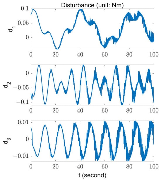
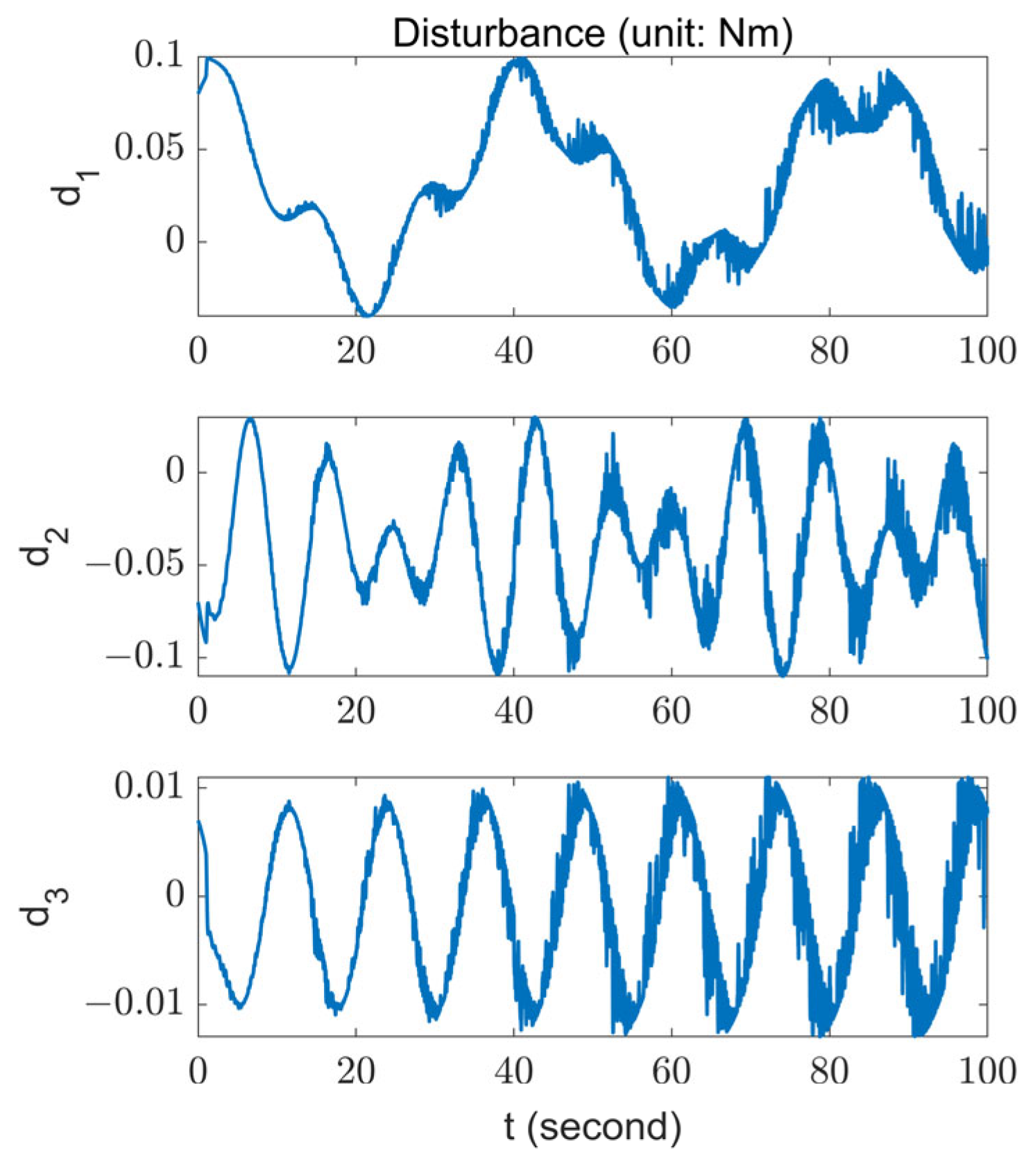
where . The external disturbance is shown in Figure 1.
Figure 1.
The external disturbance used in the simulation.
The proposed MFOLC and the ordinary OLC developed in [19] are compared. The desired attitude quaternion is , which is equivalent to a roll angle, a pitch angle, and a yaw angle. The initial state of the quadrotor is , , and . The simulation starts from and . The control parameters are listed in Table 1.
Table 1.
Control parameters chosen for simulation.
Note that according to Assumption 3, can be selected by , such that . According to Table 1, is also satisfied. In addition, to maintain hover, attitude control torques must be limited, with the maximum roll, pitch, and yaw control torque of 1 Nm, 1 Nm and 0.1 Nm, respectively.
4.1.1. Scenario 1: Without Measurement Noise
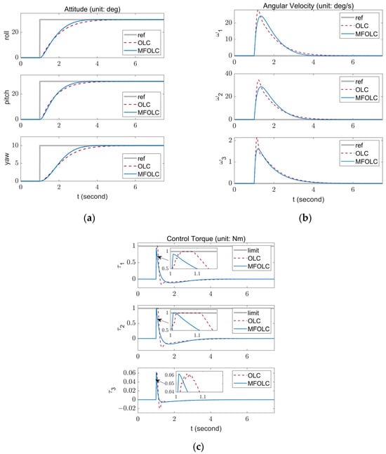
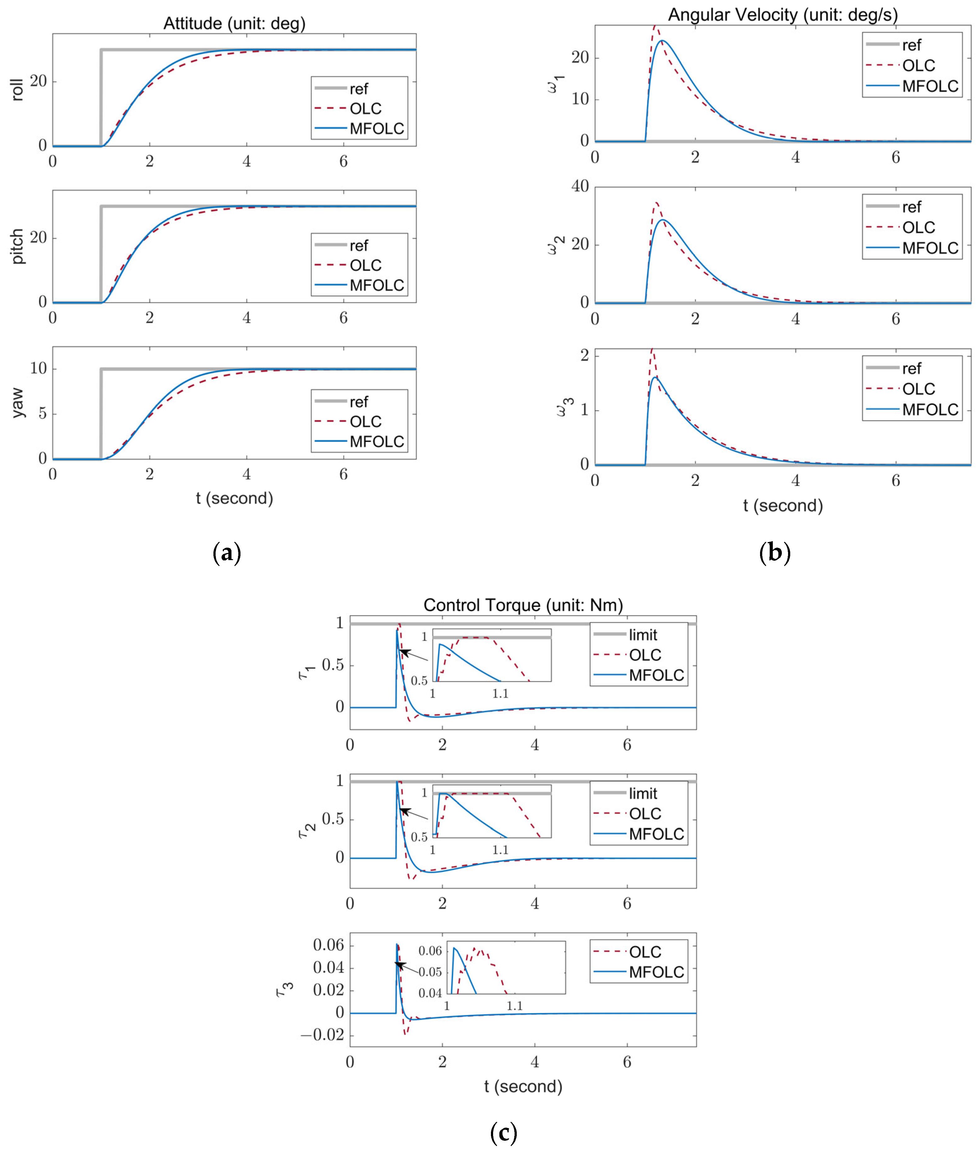
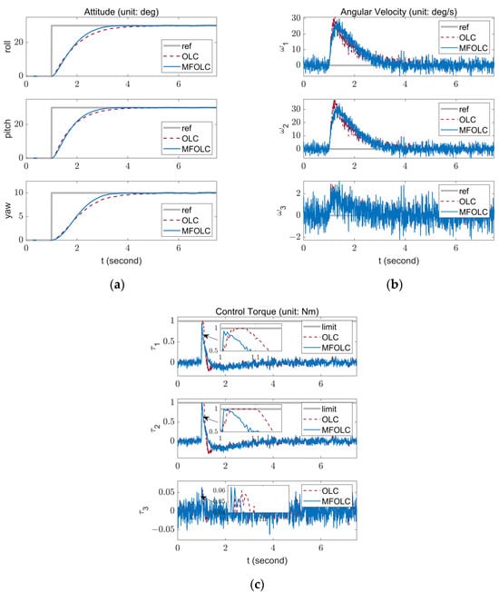
In this scenario, a relative ideal situation is simulated in which only external disturbances are acting on the quadrotor. Figure 2a–c show the simulation results for the attitude angle, the angular velocity, and the control input torque, respectively. The attitude transient-response specifications are listed in Table 2. To compare steady-state performance, the root mean square error (RMSE) of the Euler angles are calculated for both controllers. Table 3 presents the steady state RMSEs of the MFOLC and OLC from 10 to 100 s.
Figure 2.
Evolution of (a) attitude tracking; (b) angular velocity tracking; (c) control torques, without measurement noise.
Table 2.
Attitude transient-response specifications without measurement noise.
Table 3.
Steady state RMSE without measurement noise.
In Figure 2a,b, both the MFOLC and OLC can achieve a control objective within 5 s. In Table 2, the proposed MFOLC has a shorter settling time and a slight overshoot, and a smoother angular velocity trajectory. It is worth noting that the MFOLC achieves such fine performance without priori information, compared to the OLC which uses the exact inertia matrix. This is because the MFOLC uses a more flexible and intuitive parameter system.
In Table 3, the attitude steady-state error of the MFOLC is improved by 87.26% compared to that of the OLC. This is because the OLC algorithm contains the feedforward term that depends on the inertia matrix. Additionally, in the simulation, the inertia matrix has some unknown uncertainty, which affects the steady-state performance of the OLC algorithm.
In Figure 2c, the MFOLC also requests a smaller control torque than the OLC, and the duration of the control torque to reach the limit is significantly less than that of the OLC. This means a lower energy consumption for the quadrotor.
4.1.2. Scenario 2: With Angular Velocity Measurement Noise
In this scenario, not only external disturbances but also angular velocity measurement noise are acting on the quadrotor. For the consideration of engineering applications, the noisy angular velocity measurement is modeled as follows:
where is the angular velocity sensor noise, modeled as zero-mean Gaussian random variables, with variance matrix .
Figure 3a–c show the simulation results for attitude angle, angular velocity, and control input torque, respectively. The attitude transient-response specifications and steady state RMSEs from 10 to 100 s are listed in Table 4 and Table 5, respectively.
Figure 3.
Evolution of (a) attitude tracking; (b) angular velocity tracking; and (c) control torques, with angular velocity measurement noise.
Table 4.
Attitude transient-response specifications with angular velocity measurement noise.
Table 5.
Steady state RMSE with angular velocity measurement noise.
Comparing the simulation results in Section 4.1.1, the addition of angular velocity measurement noise leads to a significant increase in the overshoot and steady state RMSE for both controllers. However, the reduced performances are still in a fine performance range.
Overall, the comparative simulation shows that, both the MFOLC and OLC can realize attitude tracking control of the quadrotor in the presence of angular velocity measurement noise, model uncertainty and external disturbance. However, the MFOLC has better performance in terms of settling time, steady state control accuracy, and energy consumption.
4.2. Real-World Experiment
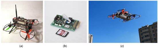
For a real-world experiment, we validate the proposed MFOLC in an outdoor environment. The quadrotor we used in the experiment is shown in Figure 4a. It is a small quadrotor designed by our team. Its power system consists of four sets of Emax RS2205 motors, kangkong 5045 three-blade propellers, and an XRotor 30A electronic speed controller (ESC). The flight controller is also self-developed, based on an STM32F407 microprocessor, as shown in Figure 4b. The onboard angular velocity sensors are three ADXRS646 micro-electro-mechanical system (MEMS) gyroscopes. The quadrotor is powered by a 3-cell LiPo battery and has a total mass of 0.9 kg. Figure 4c presents the outdoor flight picture.
Figure 4.
Photo of (a) the tested quadrotor platform; (b) Photo of the flight controller; and (c) the outdoor flight experiment.
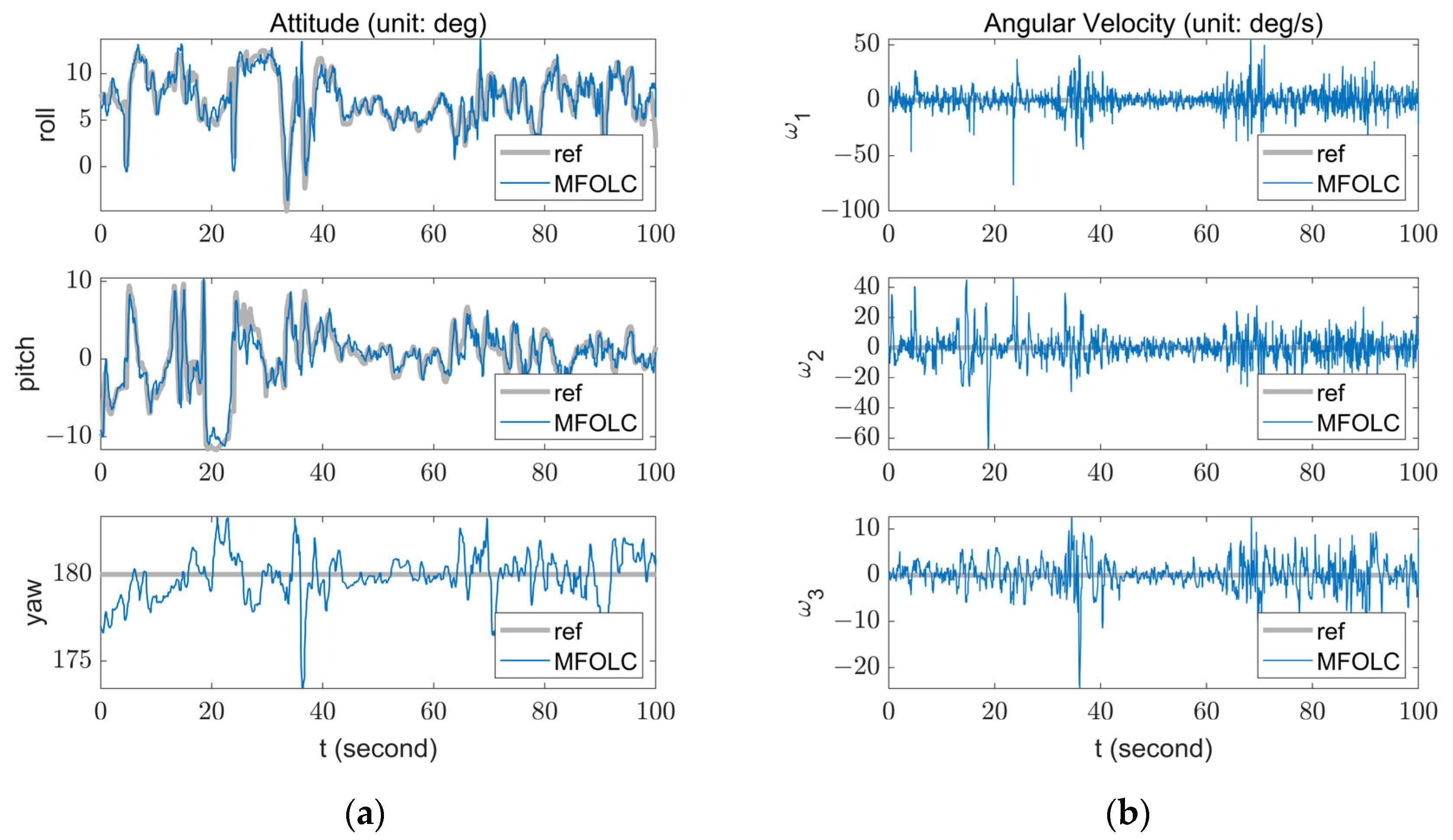
The attitude control loop ran at 200 Hz, and the control parameters were as follows: , . By using an anemometer, the wind speed at the flight field was 3.7 m/s from the east. The quadrotor performed a route flight and the proposed MFOLC tracked the target attitude provided by the position controller, and the target angular velocity and acceleration were always set to zero.
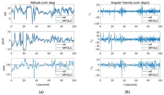
The corresponding experimental results are illustrated in Figure 5. Overall, the MFOLC exhibits a good attitude command tracking performance, while the yaw angle tracking error is relatively large. This is because the yawing torque is produced by the weak reactive torque form each rotor. To maintain hovering and other axial attitude stabilizations, the yawing torque produced by speed difference of rotors is much smaller than rolling and pitching torques, resulting in relatively large attitude tracking errors.
Figure 5.
Evolution of (a) attitude tracking; and (b) angular velocity tracking in a real-world experiment.
5. Conclusions
Although many nonlinear controllers can be used for quadrotor attitude tracking, none of them have addressed external disturbances, uncertain or even unknown model parameters, and low computational consumption simultaneously. In this paper, we developed a novel model-free online learning control scheme to achieve attitude tracking in the presence of time-varying external disturbances, uncertainties in the inertia matrix, and angular velocity sensor noises. The proposed approach guaranteed the closed-loop attitude error system to be uniformly ultimately bounded stable. An accurate inertia matrix and expensive computational consumption were not needed to implement the control law. Thus, the proposed MFOLC is quite suited for small quadrotors with compact arithmetic, which is illustrated by a real-world experiment. A remaining problem of our method is that it is not specifically designed for the input saturation limit case, especially when the quadrotor needs to maintain enough vertical thrust to resist gravity when performing attitude control tasks. Moreover, the control margin that can be allocated to attitude control is limited. Hence, in future work, we intend to further investigate the MFOLC algorithm for the input saturation limit case.
Author Contributions
Investigation, L.T. and S.Z.; Methodology, L.T.; Project administration, G.J.; Resources, L.W.; Software, G.J.; Writing—original draft, L.T.; Writing—review & editing, G.J. All authors have read and agreed to the published version of the manuscript.
Funding
The work was supported by the National Natural Science Foundation of China (No. 61673017).
Institutional Review Board Statement
Not applicable.
Informed Consent Statement
Not applicable.
Data Availability Statement
Data is contained within the article.
Conflicts of Interest
The authors declare no conflict of interest.
References
- Mahony, R.; Kumar, V.; Corke, P. Multirotor Aerial Vehicles: Modeling, Estimation, and Control of Quadrotor. IEEE Robot. Autom. Mag. 2012, 19, 20–32. [Google Scholar] [CrossRef] [Scilit]
- Hsieh, C.S.; Hsiao, D.H.; Lin, D.Y. Contour Mission Flight Planning of UAV for Photogrammetric in Hillside Areas. Appl. Sci. 2023, 13, 7666. [Google Scholar] [CrossRef] [Scilit]
- Li, Y.J.; Qiao, G.; Popov, S.; Cui, X.B.; Florinsky, I.V.; Yuan, X.H.; Wang, L.J. Unmanned Aerial Vehicle Remote Sensing for Antarctic Research: A review of progress, current applications, and future use cases. IEEE Geosci. Remote Sens. Mag. 2023, 11, 73–93. [Google Scholar] [CrossRef] [Scilit]
- Zhao, J.W.; Gao, F.F.; Jia, W.M.; Yuan, W.M.; Jin, W. Integrated Sensing and Communications for UAV Communications with Jittering Effect. IEEE Wirel. Commun. Lett. 2023, 12, 758–762. [Google Scholar] [CrossRef] [Scilit]
- Islam, M.; Okasha, M. A Comparative Study of PD, LQR and MPC on Quadrotor Using Quaternion Approach. In Proceedings of the 7th IEEE International Conference on Mechatronics Engineering (ICOM), Putrajaya, Malaysia, 30–31 October 2019; pp. 1–6. [Google Scholar]
- Khatoon, S.; Gupta, D.; Das, L.K. PID & LQR Control for a Quadrotor: Modeling and Simulation. In Proceedings of the 3rd International Conference on Advances in Computing, Communications and Informatics (ICACCI), New Delhi, India, 24–27 September 2014; pp. 796–802. [Google Scholar]
- Li, Y.B.; Song, S.X. A Survey of Control Algorithms for Quadrotor Unmanned Helicopter. In Proceedings of the IEEE 5th International Conference on Advanced Computational Intelligence (ICACI), Nanjing, China, 18–20 October 2012; pp. 365–369. [Google Scholar]
- Reyes-Valeria, E.; Enriquez-Caldera, R.; Camacho-Lara, S.; Guichard, J. LQR Control for a Quadrotor using Unit Quaternions: Modeling and Simulation. In Proceedings of the 23rd Annual International Conference on Electronics, Communications and Computing (CONIELECOMP), Cholula, Mexico, 11–13 March 2013; pp. 172–178. [Google Scholar]
- Chen, M.; Xiong, S.X.; Wu, Q.X. Tracking Flight Control of Quadrotor Based on Disturbance Observer. IEEE Trans. Syst. Man Cybern. Syst. 2021, 51, 1414–1423. [Google Scholar] [CrossRef] [Scilit]
- Wang, F.; Gao, H.M.; Wang, K.; Zhou, C.; Zong, Q.; Hua, C.C. Disturbance Observer-Based Finite-Time Control Design for a Quadrotor UAV with External Disturbance. IEEE Trans. Aerosp. Electron. Syst. 2021, 57, 834–847. [Google Scholar] [CrossRef] [Scilit]
- Li, B.; Gong, W.Q.; Yang, Y.S.; Xiao, B.; Ran, D.C. Appointed Fixed Time Observer-Based Sliding Mode Control for a Quadrotor UAV under External Disturbances. IEEE Trans. Aerosp. Electron. Syst. 2022, 58, 290–303. [Google Scholar] [CrossRef] [Scilit]
- Bisheban, M.; Lee, T. Geometric Adaptive Control With Neural Networks for a Quadrotor in Wind Fields. IEEE Trans. Control Syst. Technol. 2021, 29, 1533–1548. [Google Scholar] [CrossRef] [Scilit]
- Gao, B.K.; Liu, Y.J.; Liu, L. Adaptive neural fault-tolerant control of a quadrotor UAV via fast terminal sliding mode. Aerosp. Sci. Technol. 2022, 129, 107818. [Google Scholar] [CrossRef] [Scilit]
- Hua, H.; Fang, Y.C. A Novel Reinforcement Learning-Based Robust Control Strategy for a Quadrotor. Ieee Trans. Ind. Electron. 2023, 70, 2812–2821. [Google Scholar] [CrossRef] [Scilit]
- Zhang, Z.Z.; Yang, H.Y.; Fei, Y.Y.; Sun, C.Y.; Yu, Y. Control of UAV quadrotor using reinforcement learning and robust controller. IET Control Theory Appl. 2023, 17, 1599–1610. [Google Scholar] [CrossRef] [Scilit]
- Nagami, K.; Schwager, M. HJB-RL:Initializing Reinforcement Learning with Optimal Control Policies Applied to Autonomous Drone Racing. In Proceedings of the Conference on Robotics—Science and Systems, Electr Network, Virtual, 12–16 July 2021. [Google Scholar]
- Mu, C.X.; Zhang, Y. Learning-Based Robust Tracking Control of Quadrotor With Time-Varying and Coupling Uncertainties. Ieee Trans. Neural Netw. Learn. Syst. 2020, 31, 259–273. [Google Scholar] [CrossRef] [Scilit] [PubMed]
- Lupashin, S.; Schöllig, A.; Sherback, M.; Andrea, R.D. A simple learning strategy for high-speed quadrocopter multi-flips. In Proceedings of the 2010 IEEE International Conference on Robotics and Automation, Anchorage, AK, USA, 3–7 May 2010; pp. 1642–1648. [Google Scholar]
- Zhang, C.; Xiao, B.; Wu, J.; Li, B. On low-complexity control design to spacecraft attitude stabilization: An online-learning approach. Aerosp. Sci. Technol. 2021, 110, 106441. [Google Scholar] [CrossRef] [Scilit]
- Faessler, M.; Franchi, A.; Scaramuzza, D. Differential Flatness of Quadrotor Dynamics Subject to Rotor Drag for Accurate Tracking of High-Speed Trajectories. IEEE Robot. Autom. Lett. 2018, 3, 620–626. [Google Scholar] [CrossRef] [Scilit]
- Tayebi, A. Unit Quaternion-Based Output Feedback for the Attitude Tracking Problem. IEEE Trans. Autom. Control 2008, 53, 1516–1520. [Google Scholar] [CrossRef] [Scilit]
- Powers, C.; Mellinger, D.; Kumar, V. Quadrotor Kinematics and Dynamics. In Handbook of Unmanned Aerial Vehicles; Valavanis, K.P., Vachtsevanos, G.J., Eds.; Springer: Dordrecht, The Netherlands, 2015; pp. 307–328. [Google Scholar]
- Pounds, P.; Mahony, R.; Corke, P. Modelling and control of a large quadrotor robot. Control Eng. Pract. 2010, 18, 691–699. [Google Scholar] [CrossRef] [Scilit]
- Li, Y.M.; Tong, S.C.; Liu, L.; Feng, G. Adaptive output-feedback control design with prescribed performance for switched nonlinear systems. Automatica 2017, 80, 225–231. [Google Scholar] [CrossRef] [Scilit]
- Wu, B.L. Spacecraft Attitude Control with Input Quantization. J. Guid. Control Dyn. 2016, 39, 176–180. [Google Scholar] [CrossRef] [Scilit]

Disclaimer/Publisher’s Note: The statements, opinions and data contained in all publications are solely those of the individual author(s) and contributor(s) and not of MDPI and/or the editor(s). MDPI and/or the editor(s) disclaim responsibility for any injury to people or property resulting from any ideas, methods, instructions or products referred to in the content. |
© 2024 by the authors. Licensee MDPI, Basel, Switzerland. This article is an open access article distributed under the terms and conditions of the Creative Commons Attribution (CC BY) license (https://creativecommons.org/licenses/by/4.0/).