


Featured Application
This paper proposes virtual admittance feedforward compensation and phase correction for average-current-mode-controlled totem-pole PFC converters. It can effectively reduce total harmonic distortion (THD) and improve the power factor (PF) of the converter. The proposed control strategy can be directly used in on-board chargers (OBCs) for electric vehicles, power supplies for server clusters, communication equipment, industrial equipment, etc.
Abstract
This paper explores a current distortion problem in totem-pole bridgeless power factor correction (PFC) converters with average current mode (ACM) control. With in-depth modeling for the current and voltage loops, it was found that the current distortion is caused by the limited current loop bandwidth and input filter capacitor. These factors lead to the presence of a susceptance component in the input admittance, which degrades the power factor (PF) and total harmonic distortion (THD) of the PFC converter. To solve this problem, this paper proposes virtual admittance feedforward compensation (VAFC) and phase correction methods to adjust the input admittance to pure conductance. The VAFC can generate virtual admittance that compensates for susceptance components in the input admittance, while phase correction can generate an equivalent current source that offsets the current in input capacitors. Furthermore, a phase lock loop (PLL) is introduced to realize the VAFC, which reduces the feedforward interference caused by input voltage sampling noise. Finally, an experimental prototype was built to verify the effectiveness of the proposed strategies. According to the test results, the proposed compensation strategy improves the PF by 1.23%, while reducing the THD by 2.52% and achieving a peak efficiency of 98.69%.
1. Introduction
AC-DC power converters are widely used in industry, communication, medical treatment, and consumer electronics. When their power exceeds 75 W, power factor correction (PFC) is necessary in power electronic equipment; otherwise, the equipment will inject harmonic current into the power grid and degrade the power quality [1]. Boost PFC is the most widely used converter because of its small current pulsation and simple control [2,3,4]. However, the large conduction loss of the rectifier bridge in boosting PFC severely degrades power efficiency and induces serious electromagnetic interference (EMI) [5,6,7]. To solve these issues, extensive research has been carried out to explore PFC converter topologies [8,9,10]. Among various topologies, totem-pole bridgeless PFC is attractive owing to its advantages of high device utilization and low conduction loss [11,12,13]. To further improve power efficiency, SiC MOSFET currently tends to replace Si MOSFET in power converters [14,15,16]. However, these improvements bring new challenges to PFC converters and their control strategy.
Traditional average current mode (ACM) control is widely used in high-power applications owing to its advantages of fixed switching frequency and insensitivity to the inductor current sampling noise [17,18]. However, due to the limited current loop bandwidths under continuous conduction mode (CCM) and the influence of input filter capacitors, the input current and voltage have a non-neglectable phase difference, resulting in current distortion and efficiency degradation [19,20]. Additionally, with the phase difference, the PFC converter will operate in discontinuous conduction mode (DCM) near the input voltage zero-crossing point [21]. In this situation, the transfer function of the PFC converter would be different from that of the CCM, which further degrades the current-tracking ability. Moreover, the sampled input voltage is directly used to generate reference current. Thus, input voltage sampling noise and delay directly affect the performance of the current loop [22]. As the load decreases, the PFC converter current decreases and the current distortion becomes more serious [23].
To improve the current loop performance of power converters, feedforward compensation was used [24]. The sampled input voltage is directly used to generate the feedforward term, which induces the sampling noise to input current and degrades the power factor of the PFC converter. To reduce the feedforward interference caused by input voltage sampling noise, the input voltage is reconstructed by detecting its zero-crossing point and storing sinusoidal table in a DSP controller [25]. However, the output of the zero-crossing detection circuit contains multiple high-frequency pulses due to sampling noise, which is even worse under high output power. A voltage-senseless feedforward method is proposed, which calculates the feedforward duty cycle based on the input current [26]. But, it requires a voltage estimator to calculate the input voltage phase, which induces error in the estimation result during mode change and causes incorrect gate driving signals. Conventional feedforward methods cannot solve the problem caused by input voltage sampling noise and do not provide an in-depth theoretical analysis. Moreover, there are few studies in the literature examining the current distortion caused by input filter capacitors.
To solve the above issues, this paper proposes virtual admittance feedforward compensation (VAFC) and reference current phase correction for totem-pole PFC converters. With in-depth modeling for current and voltage loops, it was found that the limited current loop bandwidth and input filter capacitor cause a phase difference between input current and voltage. It leads to the presence of a susceptance component in the input admittance. Furthermore, VAFC and reference current phase correction are proposed to adjust the input admittance to pure conductance. The VAFC generates virtual admittance that compensates susceptance components in the input admittance, while phase correction generates an equivalent current source that offsets the current in input capacitors. A phase lock loop (PLL) is applied to realize the VAFC, to reduce the influence of input voltage sampling noise and delay. Experimental results demonstrated that the proposed method can further improve PF and reduce THD compared to conventional methods. The output voltage was processed using a notch filter to reduce the sampled voltage ripple, to improve the voltage loop bandwidth.
The rest of this paper is organized as follows. Section 2 presents the current-distortion problem in totem-pole bridgeless PFC converters. In Section 3, the virtual admittance feedforward compensation and reference current phase correction are proposed to adjust the input admittance to pure conductance. Section 4 presents the experimental results. Section 5 concludes this paper.
2. Current-Distortion Problem in Totem-Pole Bridgeless PFC Converter
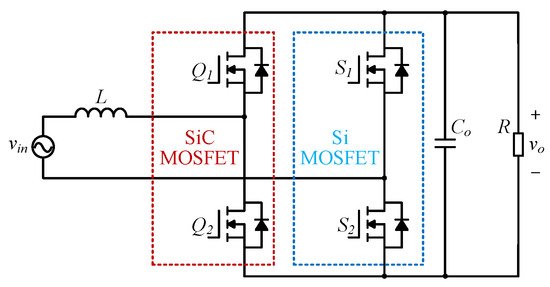
A totem-pole bridgeless PFC converter is widely used in high-power applications owing to its high-power efficiency. The topology is shown in Figure 1, where L is the inductor, Co is the output capacitor, R is the load resistor, vin is the AC input voltage, and vo is the output voltage. SiC MOSFETs Q1 and Q2 are adopted as the main power switch, to reduce the switching losses. S1 and S2 are adopted to realize synchronous rectification, which further improves the power efficiency. The PF of the converter is calculated using
where P is the active power and S is the apparent power. The total harmonic distortion is calculated using
where I1 represents the root mean square (RMS) value of the fundamental frequency component of the input current. I2, I3, …, In represent the RMS values of the harmonic frequency components of the input current, from the second harmonic to the nth harmonic.
Figure 1.
Synchronous rectification totem-pole bridgeless PFC converter based on SiC MOSFET.
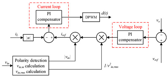
Average current mode control is widely used in totem-pole PFC converters, owing to its advantages of fixed switching frequency and insensitivity to sampling noise. A control diagram of traditional average current control is shown in Figure 2. Due to the limitation of the current loop bandwidth and input filter capacitor, the phase of the inductor current will lead the input voltage, which degrades the PF and THD. The following provides a detailed theoretical analysis from the perspective of input admittance of the PFC converter.
Figure 2.
Control block diagram of traditional average current mode control.
2.1. Current Distortion Caused by Limited Current Loop Bandwidth
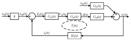
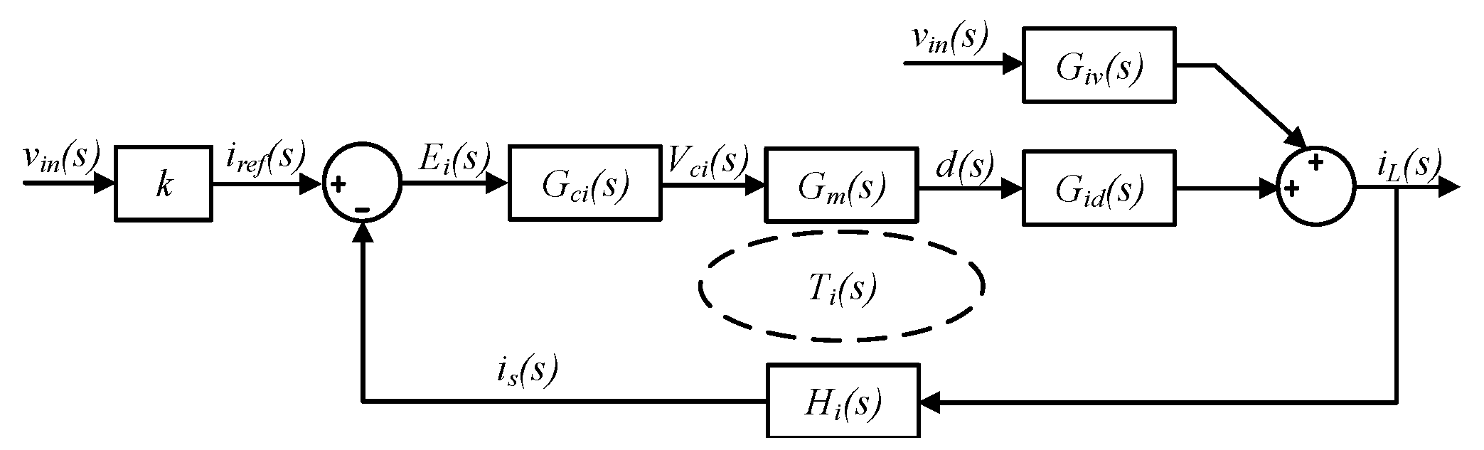
The response of the inner current loop directly determines the key performance of the PFC converter, including PF and THD. The inner current loop compares sampled average inductor current with a given sinusoidal reference. With the obtained current error, a PI compensator is adopted to calculate the duty ratio of the power switch. Then, the driving signal is generated according to the duty ratio. With the above principles, the inner current loop diagram is shown in Figure 3. where Hi(s) is the transfer function of current sampling, Gci(s) is the transfer function of current loop compensator, Gm(s) is the PWM modulation transfer function, Gid(s) is the transfer function from duty ratio to inductor current, and k = 2Po/vin, m2. Based on Figure 3, input admittance of the PFC converter is calculated as follows, to analyze the causes of the phase difference between input current and voltage.
Figure 3.
Current control loop diagram.
Note that since Gm(s) = 1/vm, Giv(s) = 1/sL, and Gid(s) = vo/sL, Equation (3) is simplified as
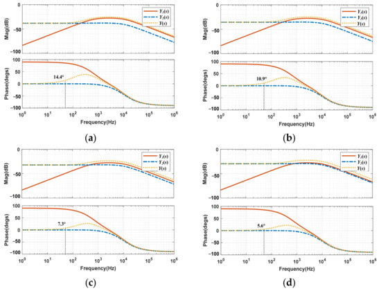
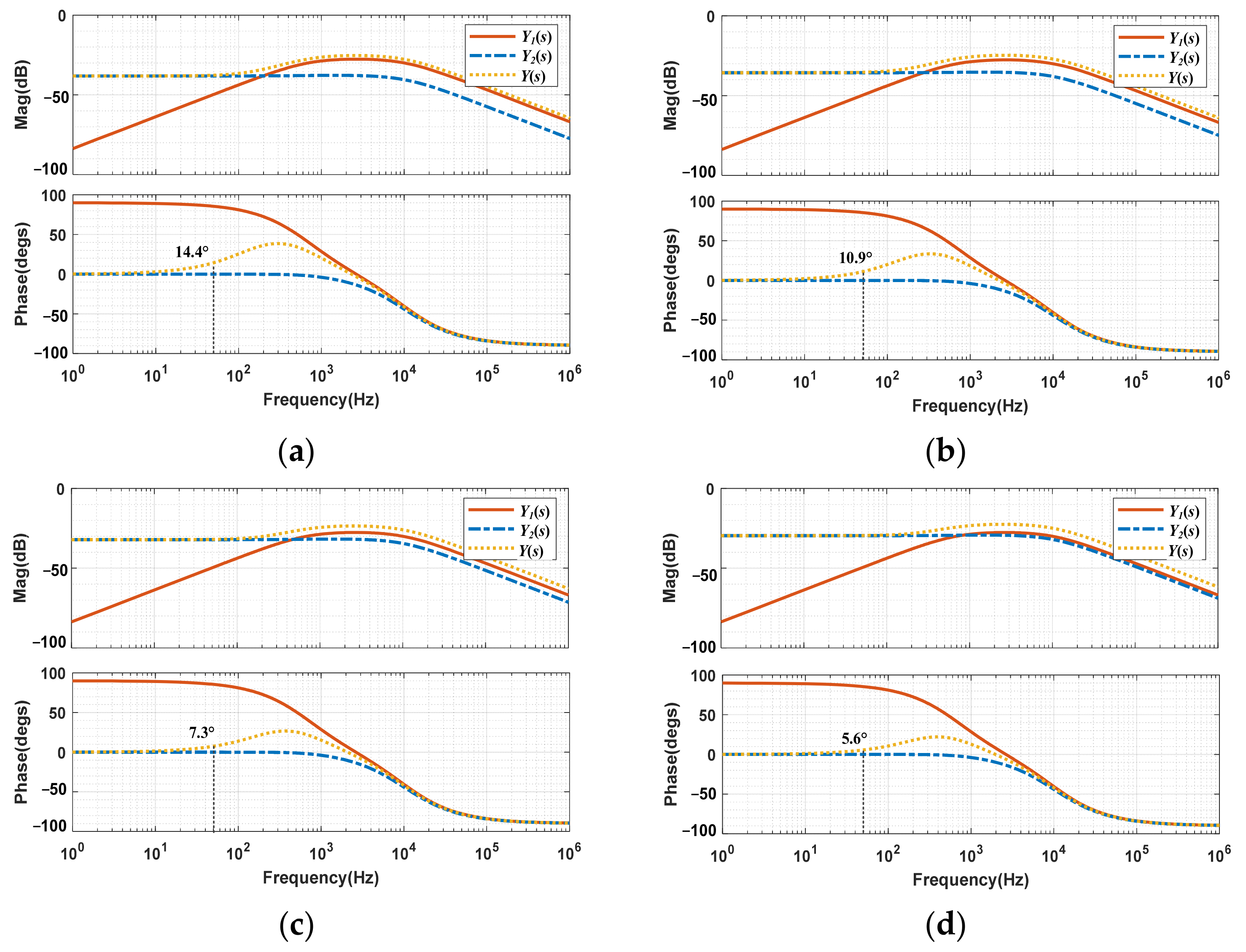
Substituting the experimental parameters into (4), where Gci(s) = 0.06 + 240/s, L = 350 μH, vm = 1, and vo = 400 V, Bode plots of the input admittance under different output power are shown in Figure 4. At 50 Hz, the phases of the input admittance at Po = 600 W, Po = 800 W, Po = 1200 W, and Po = 1600 W are 14.4°, 10.9°, 7.3°, and 5.6°, respectively. It indicates that the input admittance includes a susceptance component, resulting in capacitive current flow, particularly under light load conditions. Therefore, the input current leads the input voltage and degrades the power factor.
Figure 4.
Input admittance characteristics of the PFC converter under different output power (Po). (a) Po = 600 W. (b) Po = 800 W. (c) Po = 1200 W. (d) Po = 1600 W.
2.2. Current Distortion Caused by Input Capacitor
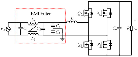
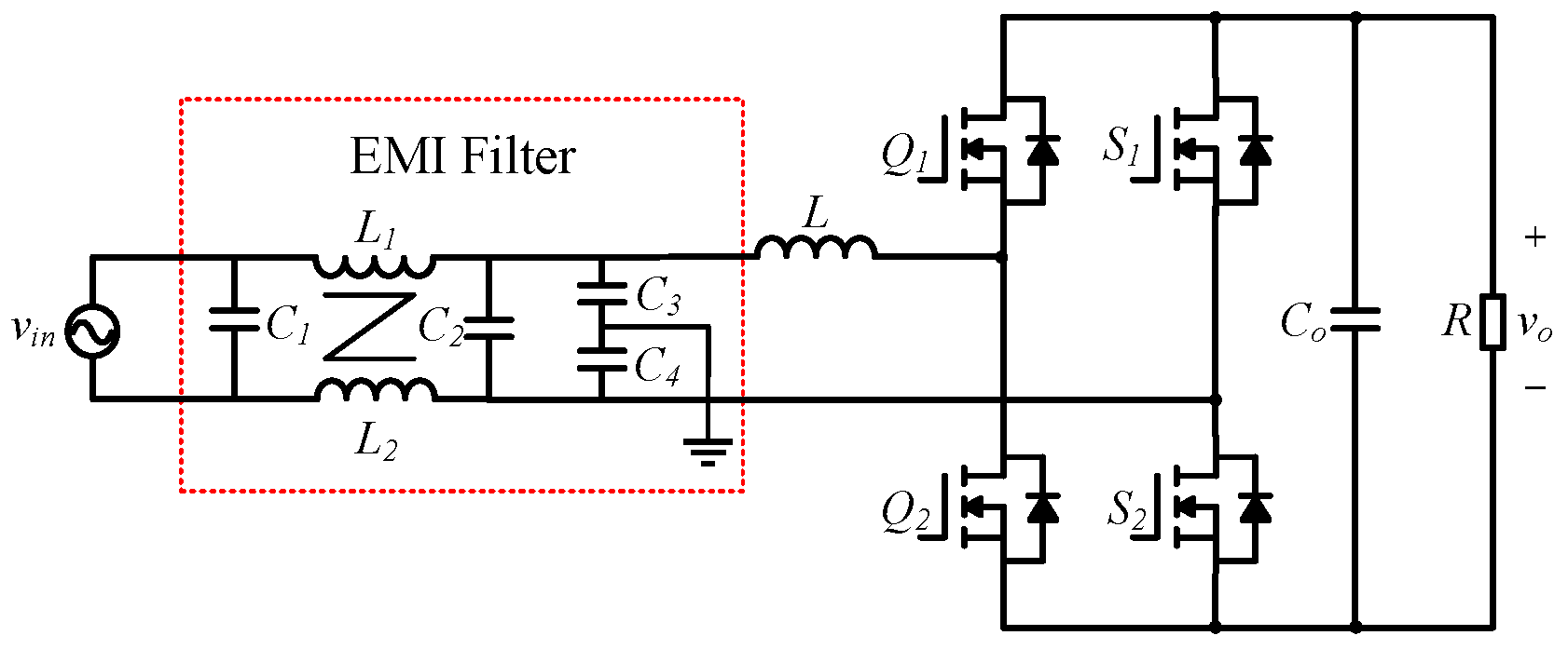
Another factor that affects PF is the input filter capacitor. In PFC converters, the AC input needs an EMI filter to reduce the high-frequency switching harmonics of the inductor current. However, the input filter capacitor generates capacitive current, which leads the input voltage and degrades PF. As shown in Figure 5, the filter adopts a single-stage structure. In this figure, C1 and C2 are X capacitors, while C3 and C4 are Y capacitors. L1 and L2 are common-mode inductors, which have small leakage inductance.
Figure 5.
EMI filter structure.
To simplify the analysis, the following assumptions are made. (a) The influence of Y capacitor is neglected since it is typically much smaller than X capacitor. (b) The equivalent input impedance of the PFC converter is Rin. The input resistance Rin is calculated with the magnitude of input voltage (vin, m) and the magnitude of the input current (iin, m), i.e.,
In this case, the phase difference caused by input capacitance is calculated using
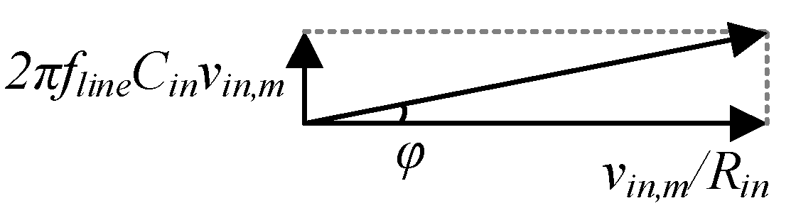
The vector of the total input current is shown in Figure 6. It shows that the input filter capacitor induces a phase difference between input current and voltage. As load power decreases, the phase difference would be even more serious, which severely degrades PF.
Figure 6.
Vector of the total input current.
3. Virtual Admittance Feedforward Compensation and Phase Correction to Reduce Current Distortion
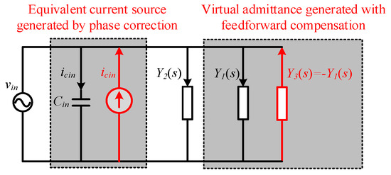
To reduce the phase difference between input current and voltage, this paper proposes VAFC and reference current phase correction. The basic idea is shown in Figure 7. With VAFC and phase correction, the input admittance is adjusted to pure conductance. As shown in this figure, the VAFC can generate virtual admittance that compensates Y1(s). The phase correction can generate an equivalent current source that offsets the current in the input capacitor.
Figure 7.
Equivalent circuit scheme under the proposed VAFC and phase correction strategy.
3.1. Virtual Admittance Feedforward Compensation
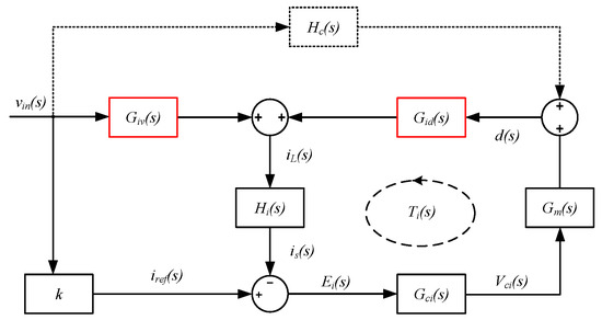
With the analysis in Section 2, the input admittance shows the resistance–capacitance characteristic due to the limited current loop bandwidth. It makes the input current lead the input voltage, which degrades the power factor. To solve this problem and improve the power factor, this paper proposes VAFC to generate virtual admittance, which neutralizes the susceptance component and adjusts the input admittance as pure conductance. Figure 8 shows the current control loop diagram with VAFC.
Figure 8.
Current control loop diagram with the proposed VAFC.
With the proposed compensation method, the input admittance of the PFC converter Y(s) is calculated as
where the virtual admittance Y3(s) is given by
With the input admittance analysis in Section 2.1, the leading phase of Y(s) is mainly caused by Y1(s). Therefore, by setting
the susceptance component is neutralized. By solving (9), the transfer function of the feedforward compensator is given by
Therefore, the feedforward term is calculated using
With the proposed VAFC, the phase difference between input current and voltage is eliminated, and the input admittance of the PFC converter becomes pure conductance. Therefore, the PF and THD of the converter are improved.
3.2. Reference Current Phase Correction
With the analysis in Section 2.2, the input filter capacitor generates capacitive current, which degrades the power factor. To eliminate the influence of the input capacitor, the reference current phase should be lagged by φ, i.e.,
where θ is the phase of the input voltage. Therefore, the total input current is calculated using
Since φ is usually small, the total input current iin,total is simplified as (14), where the input current phase error caused by the input capacitor is eliminated.
3.3. Overall Control Diagram
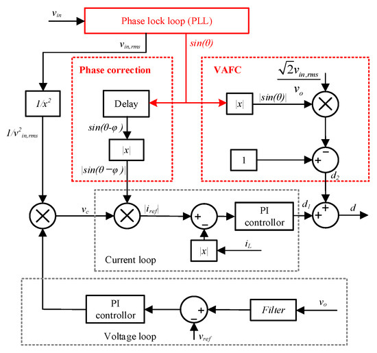
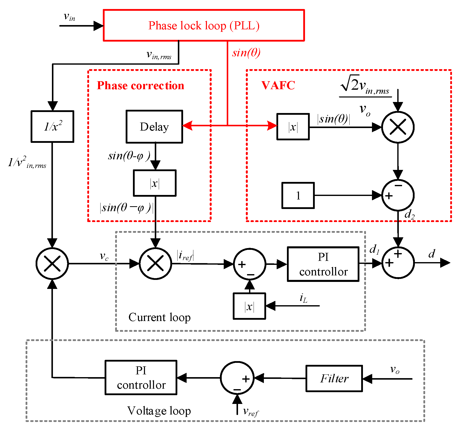
The overall block diagram of the proposed control strategy is shown in Figure 9. By realizing the proposed VAFC, the phase difference between input current and voltage caused by limited bandwidth of the current loop is reduced. The influence of the input capacitor is eliminated with the proposed reference current phase correction. Additionally, a phase lock loop is adopted in the controller, to reduce feedforward interference caused by input voltage sampling noise. A notch filter is adopted to filter line frequency ripple in output voltage sampling.
Figure 9.
Proposed control strategy for CCM totem-pole PFC converter.
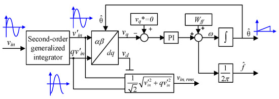
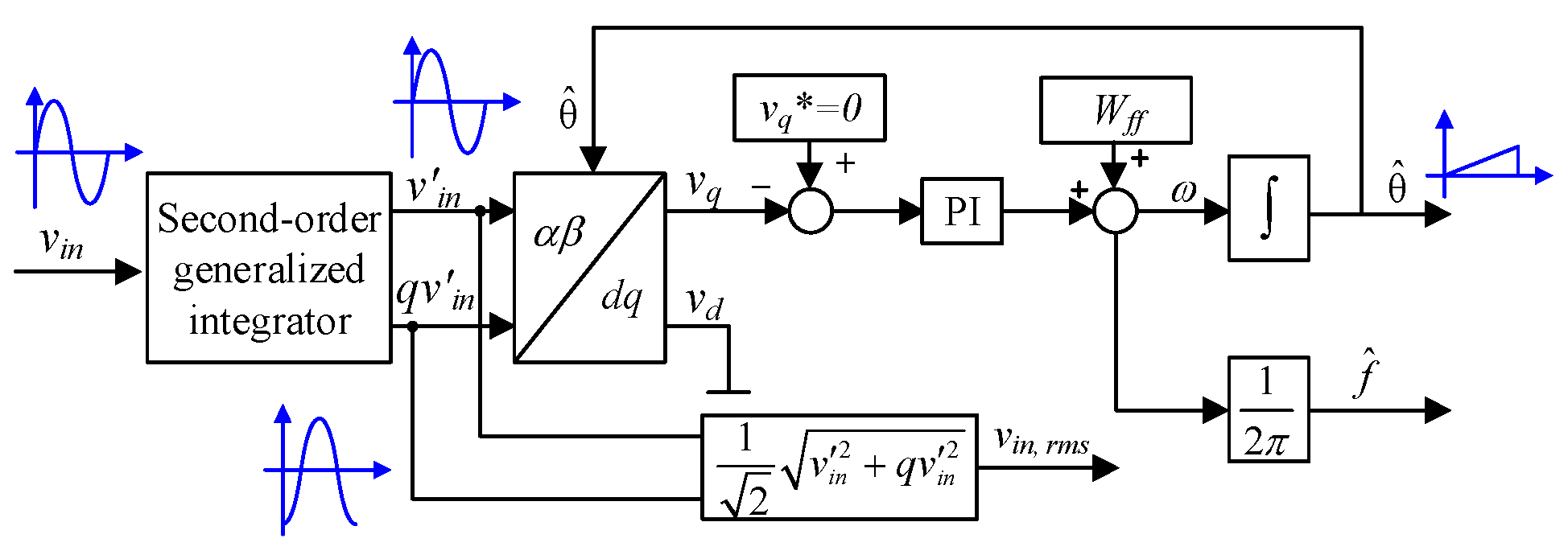
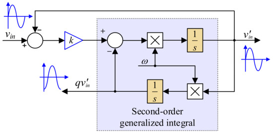
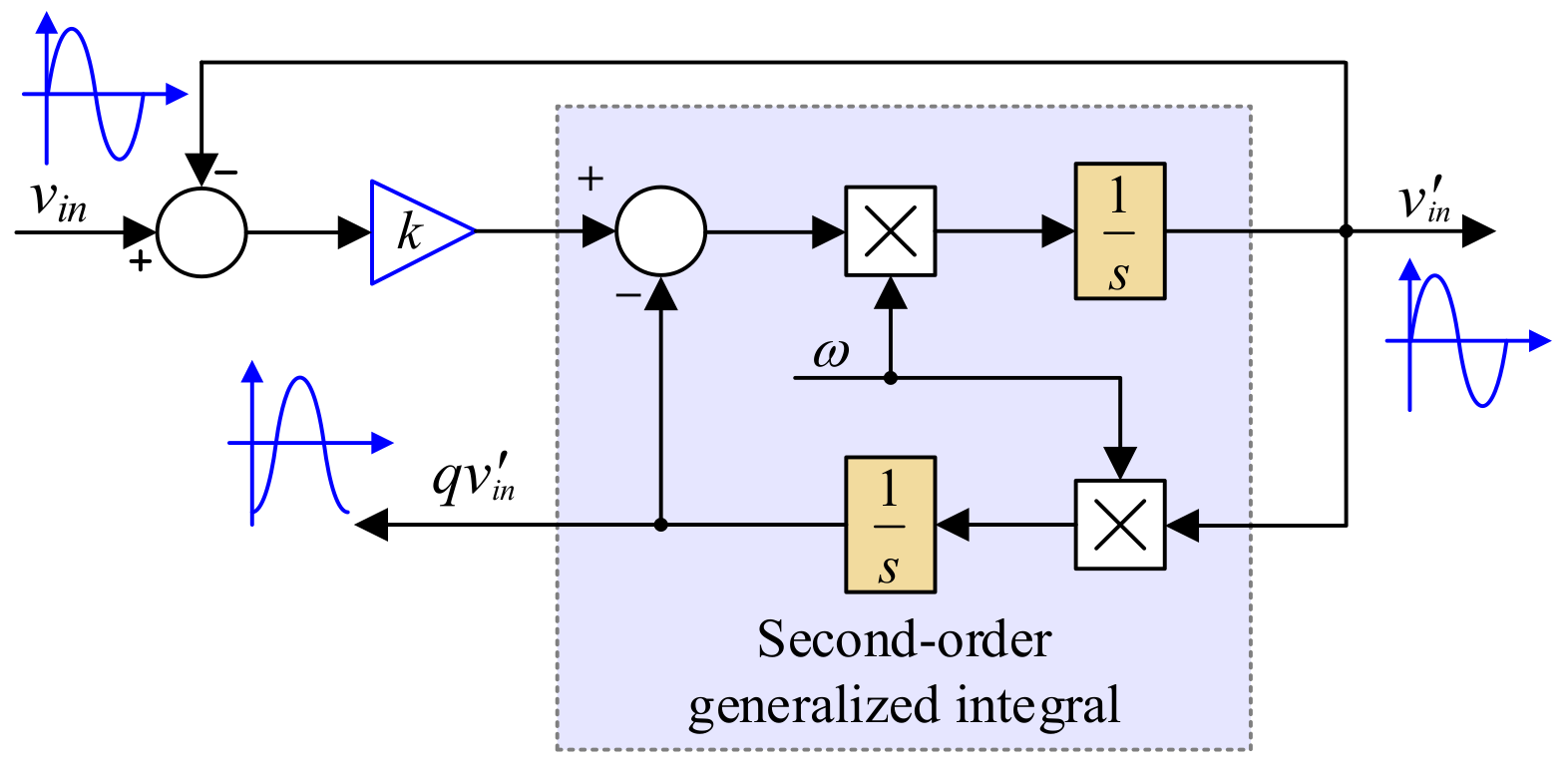
Traditional average current control methods directly use the sampled input voltage to generate reference current, which is sensitive to the delay and disturbance of the sampling circuit. To solve this problem, PLL is adopted to process the sampled input voltage. It generates an ideal sine wave that is in phase with the input voltage. The structure of PLL based on the second-order generalized integral is shown in Figure 10. The principle of the second-order generalized integrator is shown in Figure 11. The second-order generalized integrator generates the signal v’in and the orthogonal signal qv’in, and the d-axis component vd and q-axis component vq are obtained with Park transformation. Then, the q-axis component vq is adjusted to vq* with the PI controller, to realize phase-locking. The output of PLL is an ideal sine wave that is in phase with the input voltage, which is used to generate a current loop reference and solve the problems caused by the delay and disturbance of the sampling circuit. Due to the sampling and calculation delay of the PLL system, the input phase of the Park transformation () lags behind the real system, which induces an error in the Park transformation. However, given that the sampling and calculation frequency (20 kHz) is much higher than the frequency of the input signal (50 Hz), the relative error is small. Specifically, the sampling and calculation delay is 1/20 kHz = 50 μs, and the relative error is calculated as 50 μs/20 ms∙100% = 0.25%.
Figure 10.
PLL structure based on second-order generalized integrator.
Figure 11.
Second-order generalized integrator.
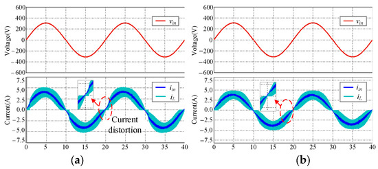
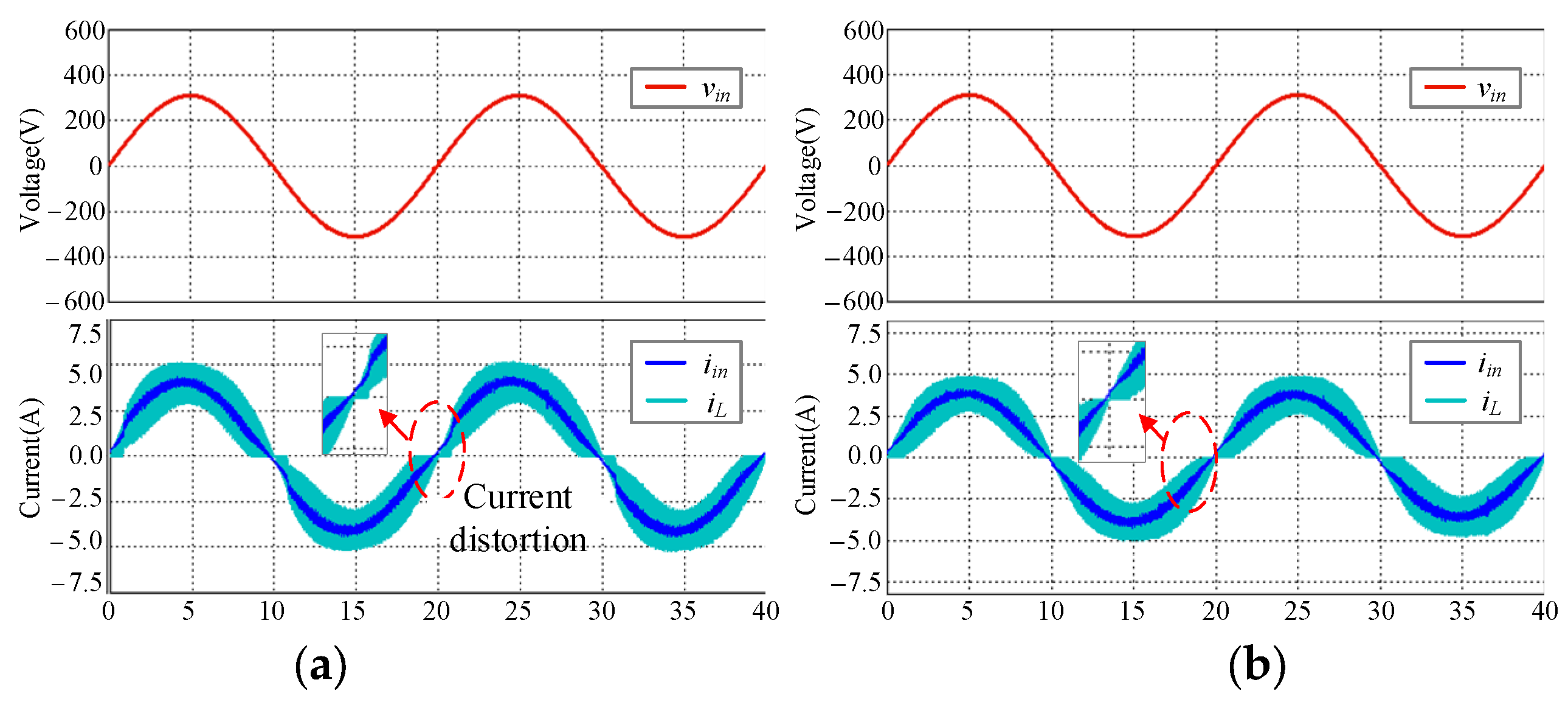
A Saber/Simulink co-simulation model was built to verify the above theory. Figure 12a shows the simulation waveform without feedforward compensation when the input power is 600 W, while Figure 12b shows the simulation waveform with the proposed VAFC. In Figure 12a, the inductor current shows a phase difference where an input voltage and current distortion exists near the input voltage zero-crossing point. With the proposed VAFC, the phase difference and current distortion is almost eliminated and the input current tracking performance is significantly improved. The harmonic analysis results of the input current show that THD is reduced to 6.12%.
Figure 12.
Simulation waveforms of PFC converter at 600 W input power. (a) Without feedforward compensation; (b) with the proposed VAFC.
4. Experimental Results
4.1. Hardware Design of the Totem-Pole Bridgeless PFC Converter
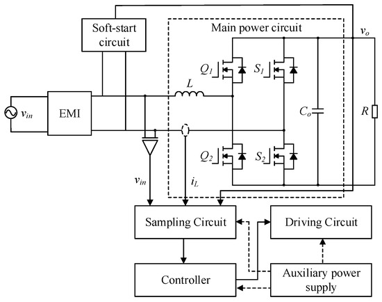
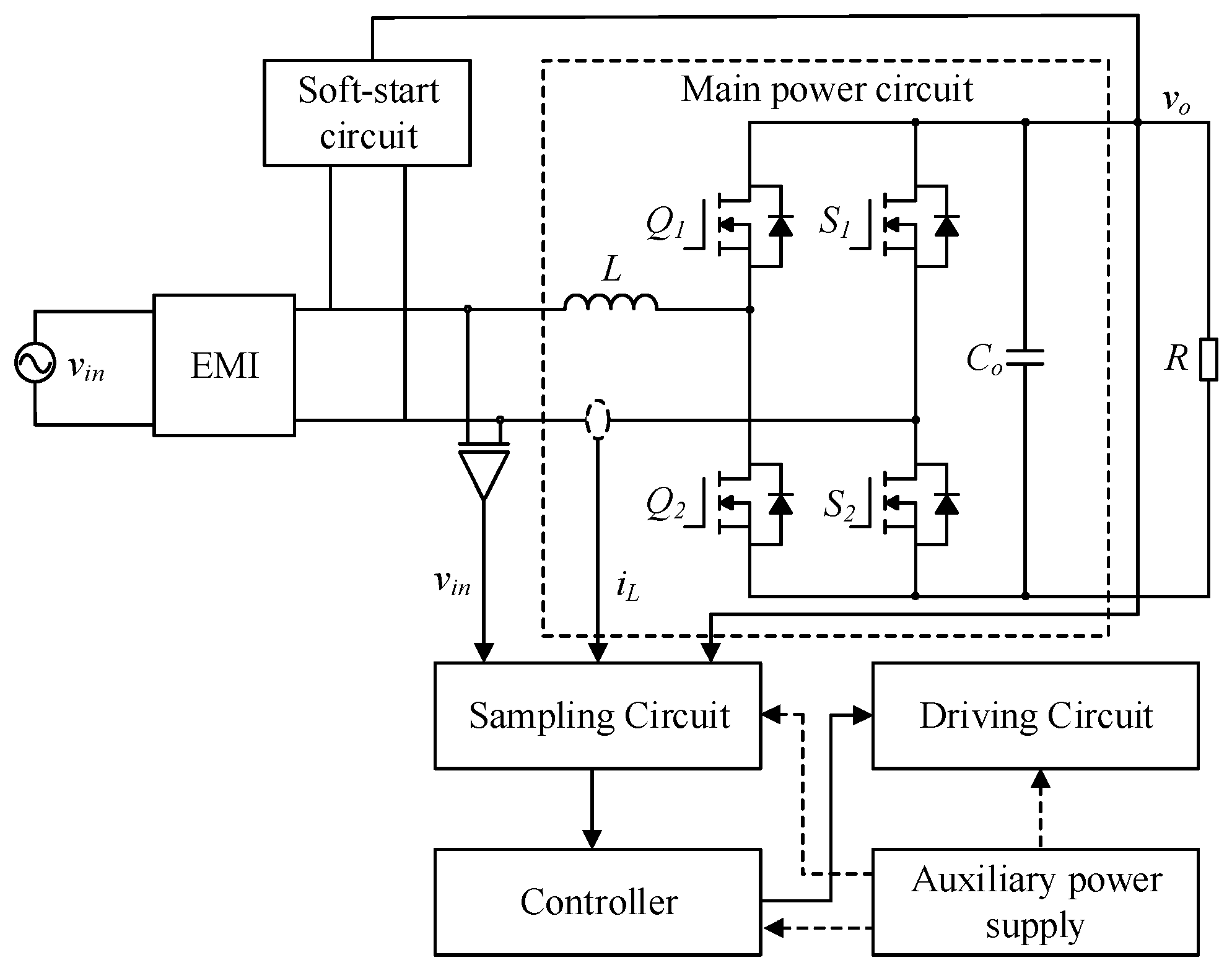
The overall structure of the totem-pole bridgeless PFC converter based on SiC devices is shown in Figure 13, which includes the main power topology, soft-start circuit, current and voltage sampling circuit, gate driving circuit, and controller. The main power topology consists of a PFC inductor, four power switches, and output bus capacitors. To ensure safety, the main power topology is electrically isolated from the control circuit.
Figure 13.
Overall block diagram of totem-pole bridgeless PFC converter.
The main specifications of the totem-pole bridgeless PFC converter designed in this paper are shown in Table 1, where vin = 220 VAC, vo = 400 VDC, Po = 1600 W, and fs = 100 kHz. The SiC MOSFET is C3M0030090K from CREE, while the Si MOSFET is IPW65R045C7 from Infineon. The inductor is 350 μH, and the output capacitor is 7 × 160 μF. The controller is TMS320F280049 from Texas Instruments.
Table 1.
Main specifications of the totem-pole bridgeless PFC converter.
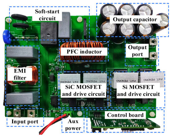
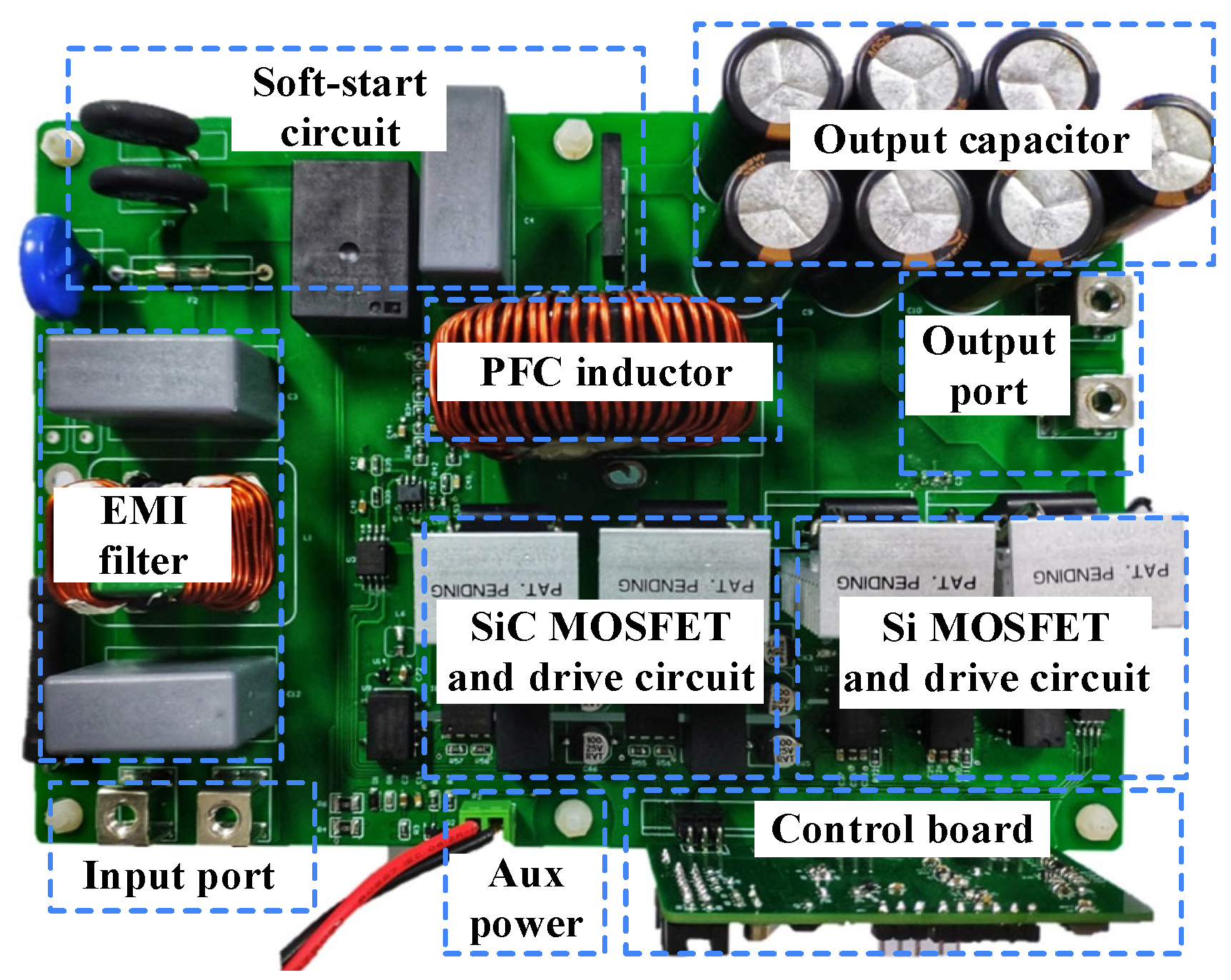
A prototype of the totem-pole bridgeless PFC is shown in Figure 14. It contains a main power board and a control board. The size of the main power board is 20 cm × 10 cm, which includes an EMI filter, soft-start circuit, PFC inductor, SiC and Si switches, a gate driving circuit, and the high-voltage side of the sampling circuit. The size of the control board is 7 cm × 4 cm, which mainly includes the peripheral circuit of the digital controller and the low-voltage side of the sampling circuit.
Figure 14.
Totem-pole bridgeless PFC prototype.
4.2. Performance Test under Different Power Rates
The input voltage is supplied by an AC source IT7326, while the load resistor is realized with electronic load AN23606E-600-420. Waveforms of input voltage, input current, inductor current, and output voltage are measured with an oscilloscope MDO3024. PF, THD, and power efficiency are measured using a power analyzer PA5000H. The input voltage is 220 VAC. The load changes from 266 Ω to 100 Ω, where the output power changes from 600 W to 1600 W. According to the PA5000H data manual, the voltage, current, and power measurement error are shown in Table 2. In the proposed system, the input signal frequency is 50 Hz, and the output signal is direct current (DC). According to Table 2, the measurement error is within 0.05%. Additionally, to ensure the accuracy and credibility of the measurement result, the following steps are carried out. (1) Calibration and verification: regularly calibrate and verify the PA5000H analyzer according to manufacturer guidelines and industry standards. This helps minimize systematic errors and ensures accurate readings. (2) Measurement uncertainty analysis: perform a comprehensive measurement uncertainty analysis for our specific measurement setup. After the analysis, it was found that connecting the input current port to the source ground side can effectively reduce the measurement error.
Table 2.
Voltage, current, and power measurement error of PA5000H.
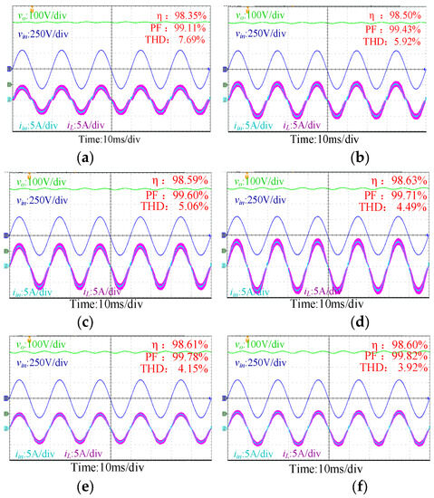
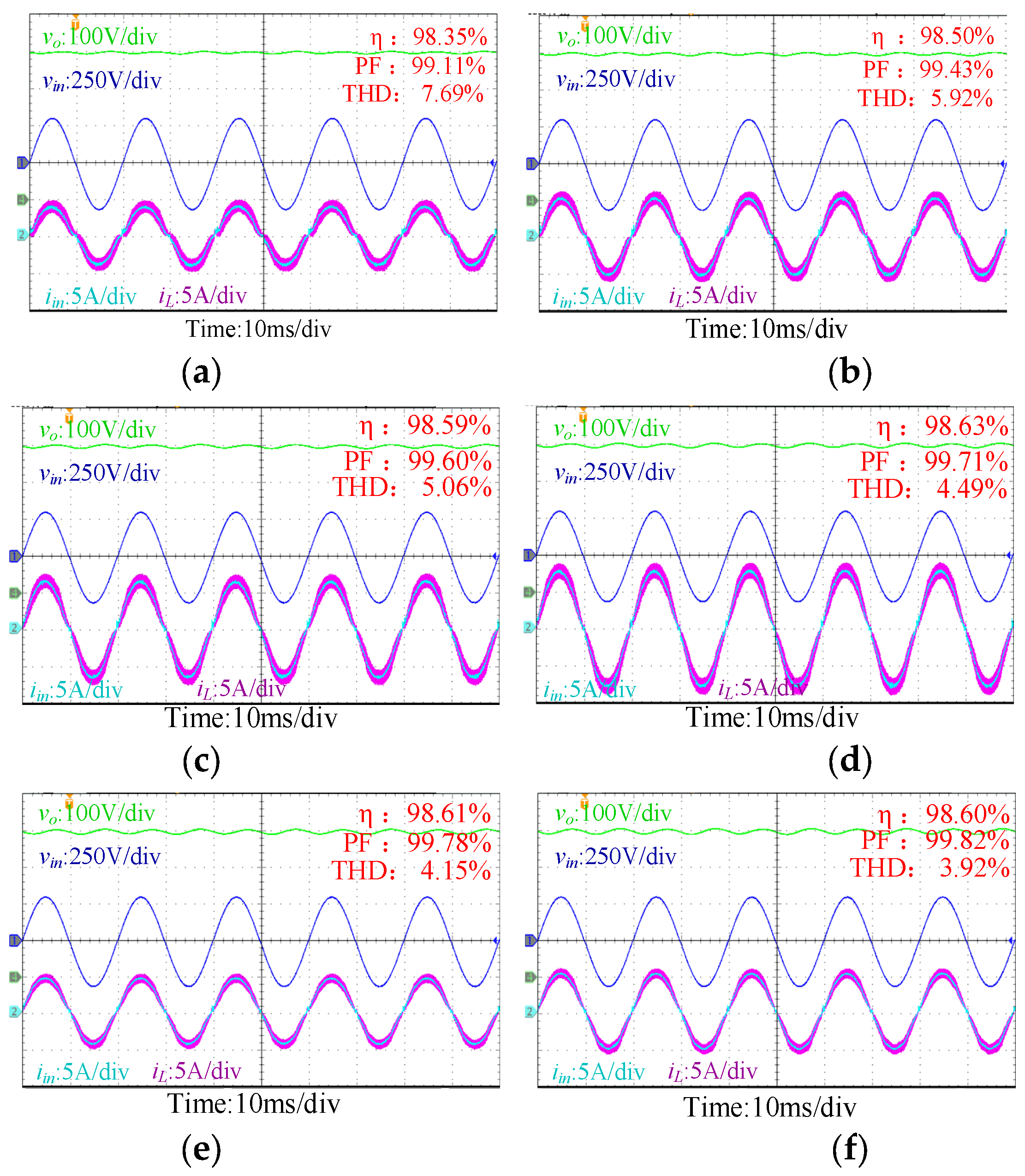
Waveforms and key performance of the PFC converter under different power rates are shown in Figure 15. The power efficiency is above 98.35% over the whole load range and achieves a peak efficiency of 98.69%. As the load power increases from 589 W to 1570 W, PF increases from 99.11% to 99.82% and THD decreases from 7.69% to 3.92%.
Figure 15.
Experimental waveforms of the prototype. (a) Po = 589 W; (b) Po = 784 W; (c) Po = 980 W; (d) Po = 1180 W; (e) Po = 1377 W; (f) Po = 1570 W.
4.3. Waveform Comparisons with and without Feedforward Compensation
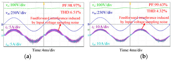
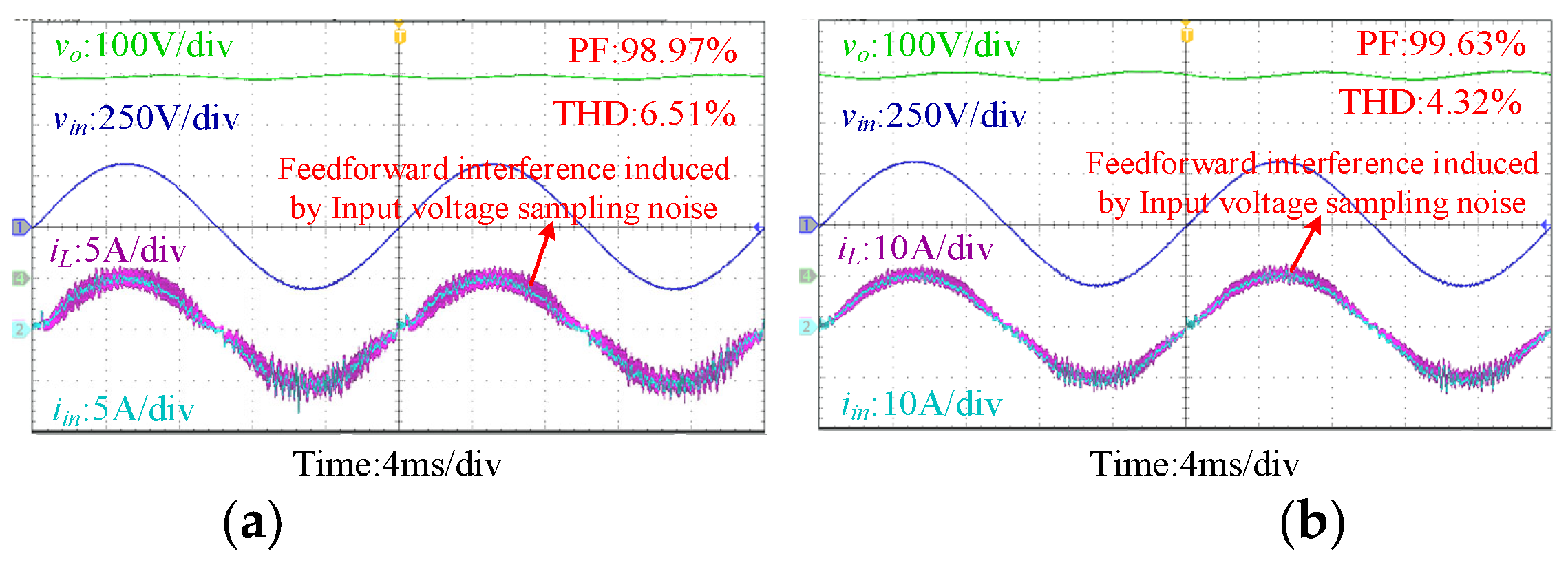
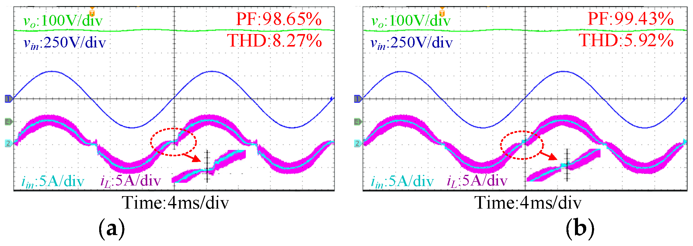
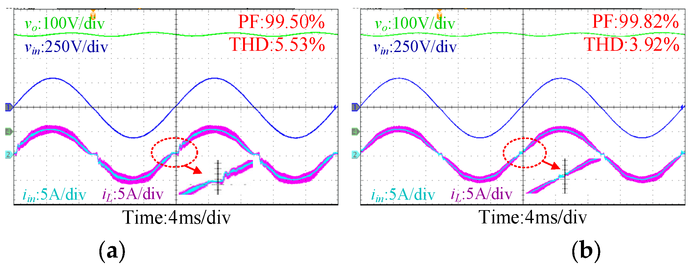
To further verify the effectiveness of the proposed control method, comparative experiments were carried out on the totem-pole bridgeless PFC prototype. The experimental results with direct input voltage feedforward are shown in Figure 16. It shows that the input current is superimposed with high-order harmonics under direct input voltage feedforward, which is induced by sampling the noise of input voltage, whereas with PLL based feedforward, the sampling noises are almost eliminated as shown in Figure 17 and Figure 18.
Figure 16.
Experimental waveforms with direct input voltage feedforward compensation: (a) 784 W; (b) 1570 W.
Figure 17.
Experimental waveforms when Po = 784 W. (a) Without feedforward compensation; (b) with the proposed VAFC.
Figure 18.
Experimental waveforms when Po = 1570 W. (a) Without feedforward compensation; (b) with the proposed VAFC.
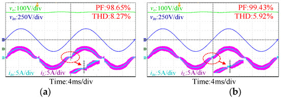
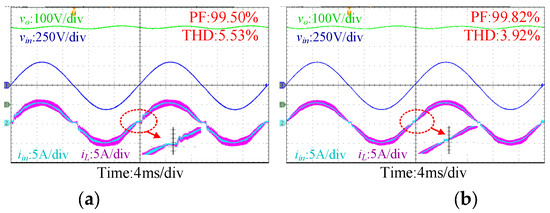
Waveforms of the input voltage, input current, inductor current, and output voltage with proposed control at Po = 784 W are shown in Figure 17. With the proposed VAFC, current distortion near the input voltage zero-crossing point is significantly reduced. PF is increased from 98.65% to 99.43%, while THD is reduced from 8.27% to 5.92%. Figure 18 shows the comparative experimental results at Po = 1570 W. Current distortion near the zero-crossing point is reduced, which improves the THD from 5.53% to 3.92% and improves the PF from 99.50% to 99.82%.
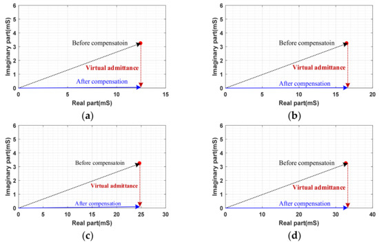
Correlations between input admittance and virtual admittance of the PFC converter at 50 Hz under different output power are shown in Figure 19. It shows that the proposed control method can generate virtual admittance to eliminate the imaginary part of the input admittance, achieving a pure conductance input characteristic. Thus, the PF and THD of the PFC converter can be improved.
Figure 19.
Correlation between input admittance and virtual admittance of the PFC converter under different output power. (a) Po = 589 W. (b) Po = 784 W. (c) Po = 1180 W. (d) Po = 1570 W.
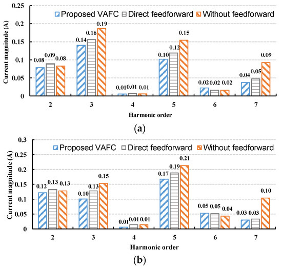
The input current harmonic analysis at Po = 784 W and Po = 1570 W are given in Figure 20a and Figure 20b, respectively. The harmonic distortion of the input current mainly comes from odd harmonic currents. With the proposed VAFC, the odd current harmonic contents, including the third and fifth harmonics of the input current are reduced, which improves PF and reduced THD.
Figure 20.
Input current harmonic analysis at different power rates. (a) Po = 784 W; (b) Po = 1570 W.
4.4. PF and THD Comparisons with and without Feedforward Compensation
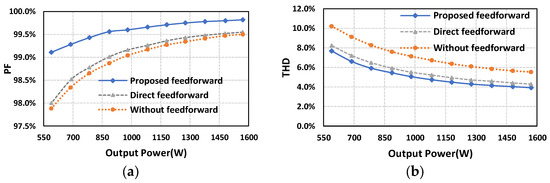
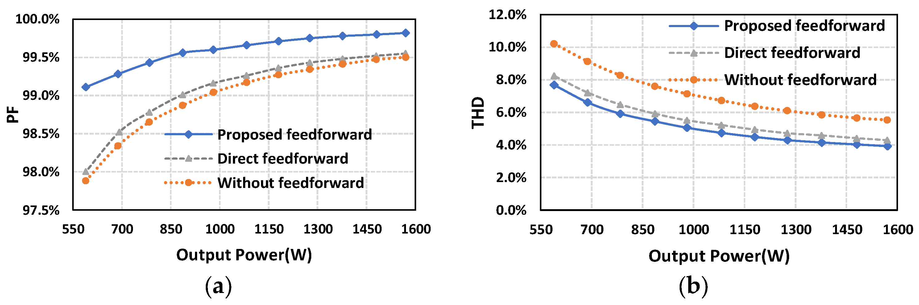
Figure 21 compares the PF and THD of the prototype with the proposed control method, with direct feedforward and without feedforward. In Figure 21a, PF of the prototype is improved via the proposed feedforward over the whole load range. At Po = 589 W, the PF with the proposed feedforward is 99.11%. Compared to direct feedforward, an improvement of 0.41% is obtained. Compared to the control method without feedforward, the PF is improved by 1.23%. At Po = 1570 W, the proposed method improves the PF from 99.50% to 99.82% compared to the control method without feedforward, and an improvement of 0.3% is achieved. In Figure 21b, the proposed method reduces the THD more than 1.61% compared to the method without feedforward. Compared to direct feedforward, the proposed method reduces the THD more than 0.37%. Because of the proposed reference current phase correction, the improvement in the PF is larger than that of THD.
Figure 21.
PF and THD curves of the prototype with respect to power rates under different control (a) PF; (b) THD.
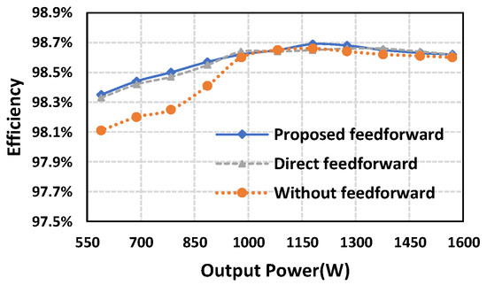
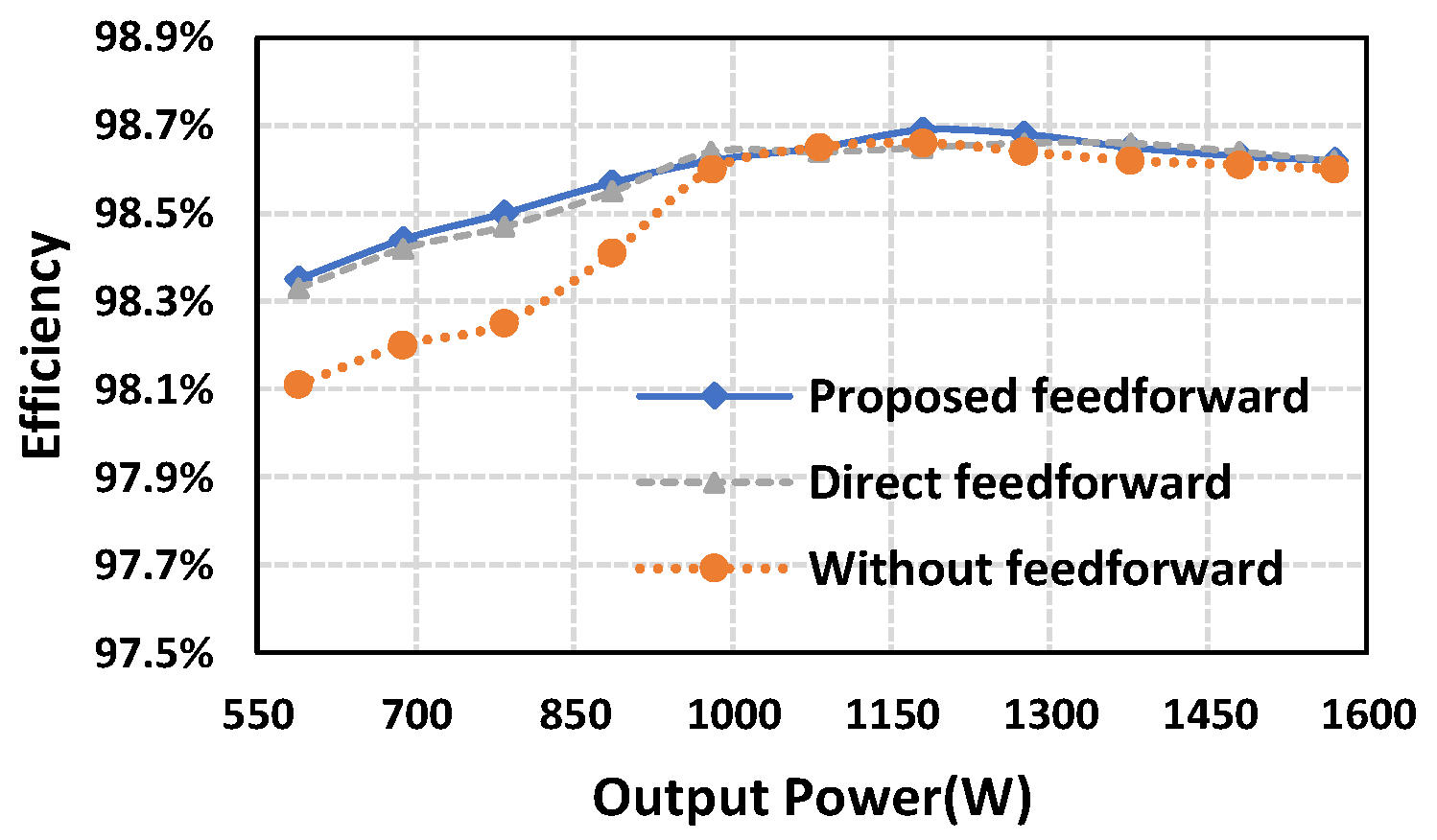
Figure 22 shows an efficiency comparison of the prototype. The efficiency is improved at light load, where an improvement of 0.24% is achieved at Po = 589 W. The peak efficiency is 98.69% at about 1250 W, and the efficiency is 98.62% at rated power.
Figure 22.
Power efficiency of the prototype.
5. Conclusions
This paper proposes virtual admittance feedforward compensation (VAFC) and reference current phase correction to adjust the input admittance of the PFC converter to pure conductance. By thoroughly modeling the current loop and calculating input admittance of the PFC converter, it was found that the current distortion is caused by the limited bandwidth and input filter capacitor. With the proposed VAFC and input current phase correction, the input admittance is tuned as pure conductance, which improves PF and reduces THD. The VAFC is realized based on a phase lock loop, which avoids the interference induced by input voltage sampling noise. A SiC-based totem-pole PFC converter is built to verify the effectiveness of the proposed method. The proposed controller can generate a virtual admittance of 0–3.2 mS, which eliminates the imaginary part of the input admittance under various load power. Thus, the proposed control can achieve a pure conductance input characteristic. Under the proposed control, the phase of the input current is near 0, which improves the PF and THD of the converter.
Author Contributions
Conceptualization, F.Z.; Data curation, H.H.; Formal analysis, D.Z.; Investigation, H.H.; Methodology, H.H.; Project administration, A.Z.; Resources, A.Z.; Software, H.H.; Supervision, X.Z.; Validation, J.Y. and M.W.; Visualization, H.H.; Writing—original draft, H.H.; Writing—review and editing, D.Z. All authors have read and agreed to the published version of the manuscript.
Funding
This work was supported by the Ministry of Industry and Information Technology of the People’s Republic of China; Science and Technology Project of State Grid Corporation of China Headquarters (5700-202258309A-2-0-QZ) Research on low-propagation-delay and high-stability digital gate driver chip technology for high-voltage and high-power silicon carbide (SiC) power device.
Institutional Review Board Statement
Not applicable.
Informed Consent Statement
Not applicable.
Acknowledgments
This work was supported by Huazhong University of Science and Technology and Beijing Institute of Spacecraft System Engineering.
Conflicts of Interest
The authors declare no conflict of interest.
References
- Collin, A.J.; Drapela, J.; Langella, R.; Testa, A. Emission assessment of single-phase switch-mode PFC loads up to 150 kHz: Experimental analysis and modelling. Electr. Power Syst. Res. 2023, 220, 109236. [Google Scholar] [CrossRef] [Scilit]
- Lopez, V.M.; Azcondo, F.J.; de Castro, A.; Zane, R. Universal Digital Controller for Boost CCM Power Factor Correction Stages Based on Current Rebuilding Concept. IEEE Trans. Power Electron. 2014, 29, 3818–3829. [Google Scholar] [CrossRef] [Scilit]
- Rosa, A.H.R.; Morais, L.M.F.; Fortes, G.O.; Seleme Júnior, S.I. Practical considerations of nonlinear control techniques applied to static power converters: A survey and comparative study. Int. J. Electr. Power Energy Syst. 2021, 127, 106545. [Google Scholar] [CrossRef] [Scilit]
- Szekely, N.C.; Salcu, S.I.; Suciu, V.M.; Pintilie, L.N.; Fasola, G.I.; Teodosescu, P.D. Power Factor Correction Application Based on Independent Double-Boost Interleaved Converter (IDBIC). Appl. Sci. 2022, 12, 7209. [Google Scholar] [CrossRef] [Scilit]
- Tiwari, S.; Basu, S.; Undeland, T.M.; Midtgård, O.M. Efficiency and Conducted EMI Evaluation of a Single-Phase Power Factor Correction Boost Converter Using State-of-the-Art SiC Mosfet and SiC Diode. IEEE Trans. Ind. Appl. 2019, 55, 7745–7756. [Google Scholar] [CrossRef] [Scilit]
- Singh, A.; Mallik, A.; Khaligh, A. A Comprehensive Design and Optimization of the DM EMI Filter in a Boost PFC Converter. IEEE Trans. Ind. Appl. 2018, 54, 2023–2031. [Google Scholar] [CrossRef] [Scilit]
- Benyamina, A.; Moulahoum, S.; Colak, I.; Bayindir, R. Design and real time implementation of adaptive neural-fuzzy inference system controller based unity single phase power factor converter. Electr. Power Syst. Res. 2017, 152, 357–366. [Google Scholar] [CrossRef] [Scilit]
- Chen, Z.; Liu, B.; Yang, Y.; Davari, P.; Wang, H. Bridgeless PFC Topology Simplification and Design for Performance Benchmarking. IEEE Trans. Power Electron. 2021, 36, 5398–5414. [Google Scholar] [CrossRef] [Scilit]
- Chen, Z.; Davari, P.; Wang, H. Single-Phase Bridgeless PFC Topology Derivation and Performance Benchmarking. IEEE Trans. Power Electron. 2020, 35, 9238–9250. [Google Scholar] [CrossRef] [Scilit]
- Ortiz-Castrillón, J.R.; Mejía-Ruíz, G.E.; Muñoz-Galeano, N.; López-Lezama, J.M.; Saldarriaga-Zuluaga, S.D. PFC Single-Phase AC/DC Boost Converters: Bridge, Semi-Bridgeless, and Bridgeless Topologies. Appl. Sci. 2021, 11, 7651. [Google Scholar] [CrossRef] [Scilit]
- Huang, Q.; Ma, Q.; Yu, R.; Chen, T.; Huang, A.Q.; Liu, Z. Improved analysis, design and control for interleaved dual-phase ZVS GaN-based totem-pole PFC rectifier with coupled inductor. In Proceedings of the 2018 IEEE Applied Power Electronics Conference and Exposition (APEC), San Antonio, TX, USA, 4–8 March 2018; pp. 2077–2083. [Google Scholar]
- Amiri, P.; Eberle, W.; Gautam, D.; Botting, C. An Adaptive Method for DC Current Reduction in Totem Pole Power Factor Correction Converters. IEEE Trans. Power Electron. 2021, 36, 11900–11909. [Google Scholar] [CrossRef] [Scilit]
- Kumar, V.; Yi, K. Single-Phase, Bidirectional, 7.7 kW Totem Pole On-Board Charging/Discharging Infrastructure. Appl. Sci. 2022, 12, 2236. [Google Scholar] [CrossRef] [Scilit]
- Zhang, C.; Qu, K.; Hu, B.; Wang, J.; Yin, X.; Shen, Z.J. A High-Frequency Dynamically Coordinated Hybrid Si/SiC Interleaved CCM Totem-Pole Bridgeless PFC Converter. IEEE J. Emerg. Sel. Top. Power Electron. 2022, 10, 2088–2100. [Google Scholar] [CrossRef] [Scilit]
- Ali, A.I.M.; Takeshita, T.; Sayed, M.A. In depth mathematical-analysis and experimentation of high-power SiC-FET based single-stage three-phase differential-based flyback inverter with practical design issues for grid-tied applications. Int. J. Electr. Power Energy Syst. 2022, 140, 108041. [Google Scholar] [CrossRef] [Scilit]
- Piriienko, S.; Röser, T.; Neuburger, M.; Balakhontsev, A. Current source gate drivers for 3-phase VSI operated in small-scale wind turbine systems. Int. J. Electr. Power Energy Syst. 2022, 141, 108160. [Google Scholar] [CrossRef] [Scilit]
- Zhang, R.; Liu, S.; Li, B.; Zhao, N.; Wang, G.; Xu, D. Totem-Pole Bridgeless Boost PFC Converter Based on GaN HEMT for Air Conditioning Applications. In Proceedings of the 2018 2nd IEEE Conference on Energy Internet and Energy System Integration (EI2), Beijing, China, 20–22 October 2018; pp. 1–9. [Google Scholar]
- Karaarslan, A.; Iskender, I. Analysis and comparison of current control methods on bridgeless converter to improve power quality. Int. J. Electr. Power Energy Syst. 2013, 51, 1–13. [Google Scholar] [CrossRef] [Scilit]
- Wang, L.; Wu, Q.H.; Tang, W.H.; Yu, Z.Y.; Ma, W. CCM-DCM average current control for both continuous and discontinuous conduction modes boost PFC converters. In Proceedings of the 2017 IEEE Electrical Power and Energy Conference (EPEC), Saskatoon, SK, Canada, 22–25 October 2017; pp. 1–6. [Google Scholar]
- Kim, J.W.; Moon, G.W. Minimizing Effect of Input Filter Capacitor in a Digital Boundary Conduction Mode Power Factor Corrector Based on Time-Domain Analysis. IEEE Trans. Power Electron. 2016, 31, 3827–3836. [Google Scholar] [CrossRef] [Scilit]
- Memon, A.H.; Baloach, M.H.; Sahito, A.A.; Soomro, A.M.; Memon, Z.A. Achieving High Input PF for CRM Buck-Buck/Boost PFC Converter. IEEE Access 2018, 6, 79082–79093. [Google Scholar] [CrossRef] [Scilit]
- Chrin, P.; Bunlaksananusorn, C. Novel Current Feedforward Average Current Mode Control Technique to Improve Output Dynamic Performance of DC-DC Converters. In Proceedings of the 2007 7th International Conference on Power Electronics and Drive Systems, Bangkok, Thailand, 27–30 November 2007; pp. 1416–1421. [Google Scholar]
- Youn, H.S.; Lee, J.B.; Baek, J.I.; Moon, G.W. A Digital Phase Leading Filter Current Compensation (PLFCC) Technique for CCM Boost PFC Converter to Improve PF in High Line Voltage and Light Load Conditions. IEEE Trans. Power Electron. 2016, 31, 6596–6606. [Google Scholar] [CrossRef] [Scilit]
- Sype, D.M.V.d.; Koen De, G.; Bossche, A.P.M.V.d.; Melkebeek, J.A. Duty-ratio feedforward for digitally controlled boost PFC converters. IEEE Trans. Ind. Electron. 2005, 52, 108–115. [Google Scholar] [CrossRef]
- Zhao, W.; Liu, B.; Duan, S.; Sheng, W.; Wu, M.; Song, Z. A Digital Control Method with Feedforward Reconstruction for Improved Sampling Interference Suppression in GaN HEMTs based Totem-pole PFC Converters. In Proceedings of the 2018 1st Workshop on Wide Bandgap Power Devices and Applications in Asia (WiPDA Asia), Xi’an, China, 16–18 May 2018; pp. 1–6. [Google Scholar]
- Park, S.M.; Lee, Y.D.; Park, S.Y. Voltage sensorless feedforward control of a dual boost PFC converter for battery charger applications. In Proceedings of the 2011 IEEE Energy Conversion Congress and Exposition, Phoenix, AZ, USA, 17–22 September 2011; pp. 1376–1380. [Google Scholar]

Disclaimer/Publisher’s Note: The statements, opinions and data contained in all publications are solely those of the individual author(s) and contributor(s) and not of MDPI and/or the editor(s). MDPI and/or the editor(s) disclaim responsibility for any injury to people or property resulting from any ideas, methods, instructions or products referred to in the content. |
© 2023 by the authors. Licensee MDPI, Basel, Switzerland. This article is an open access article distributed under the terms and conditions of the Creative Commons Attribution (CC BY) license (https://creativecommons.org/licenses/by/4.0/).