Abstract
Auxetic structures possess a negative Poisson ratio (ν < 0) as a result of their geometrical configuration, which exhibits enhanced indentation resistance, fracture toughness, and impact resistance, as well as exceptional mechanical response advantages for applications in defense, biomedical, automotive, aerospace, sports, consumer goods, and personal protective equipment sectors. With the advent of additive manufacturing, it has become possible to produce complex shapes with auxetic properties, which could not have been possible with traditional manufacturing. Three-dimensional printing enables easy and precise control of the geometry and material composition of the creation of desirable shapes, providing the opportunity to explore different geometric aspects of auxetic structures with a variety of different materials. This study investigated the geometrical and material combinations that can be jointly tailored to optimize the auxetic effects of 2D and 3D complex structures by integrating design, modelling approaches, 3D printing, and mechanical testing. The simulation-driven design methodology allowed for the identification and creation of optimum auxetic prototype samples manufactured by 3D printing with different polymer materials. Compression tests were performed to characterize the auxetic behavior of the different system configurations. The experimental investigation demonstrated a Poisson’s ration reaching a value of ν = −0.6 for certain shape and material combinations, thus providing support for preliminary finite element studies on unit cells. Finally, based on the experimental tests, 3D finite element models with elastic material formulations were generated to replicate the mechanical performance of the auxetic structures by means of simulations. The findings showed a coherent deformation behavior with experimental measurements and image analysis.
1. Introduction
Some of the major structural advantages of sandwich composites are the high stiffness-to-weight ratio and the high bending strength-to-weight ratio. The sandwich increases the flexural rigidity of structures without adding substantial weight. The design and manufacturing of lightweight composite structures for protective purposes are of interest for both defense and civilian applications, including aircraft, sports, automotive, and consumer goods [1,2]. Sandwich structures demonstrate interesting characteristics, such as high-energy absorption capacity, high strength, and improved stability [3]. A traditional sandwich panel consists of a low-density core, mainly in the honeycomb or porous structures, and two stiff metal or composite faces. Honeycomb matrix structures are favored in sandwich applications due to their impact resistance and energy absorption characteristics [4]. However, in recent years, experiments on sandwich composites with auxetic materials resulted in deformation reduction, higher flexure response, and energy absorption potential when compared with honeycomb structures [5,6].
The main objective of this article is to study, develop, and analyze additively manufactured auxetic cores as an alternative solution to conventional honeycombs in sandwich structures for impact applications. Auxetic structures (ν < 0), in contrast to conventional structures (ν > 0), exhibit enhanced indentation resistance, fracture toughness, and impact resistance as well as an exceptional mechanical response [7,8]. These superior properties established auxetics as ideal materials for a broad range of applications, mainly in the area of light-weight structures, due to their ability to achieve high stiffness and a large surface-to-volume ratio, which are pertinent for applications in defense, sports, and personal protective equipment sectors [1,9,10,11]. From the manufacturing perspective, 2D auxetic structures are simpler and less expensive to fabricate than 3D structures. However, with the advent of additive manufacturing, it has become possible to produce complex shapes that cannot be realized by traditional manufacturing processes. Three-dimensional printing enables easy and precise control of both the geometry and the material composition of complex shapes, which provides an opportunity to explore different geometric aspects of auxetic core structures. Research studies in this field have been performed by [12,13,14] with a variety of core materials.
This study presents different geometrical and material combinations that can be jointly tailored, with the aim to investigate the auxetic effects of 2D and 3D complex structures. This was facilitated by integrating CAD design, FEM modelling approaches, 3D printing, and mechanical testing. The advantages of additive manufacturing were engaged in the simulation-driven design methodology to allow for the identification of unit cell geometrical features with increased auxetic responses. Following this process, auxetic prototype systems were fabricated by means of 3D printing with different polymer material combinations. Then, their auxetic behavior was investigated experimentally by means of compression tests and computationally with the aid of finite element analysis. With the use of such proposed auxetic systems, the mechanical requirements of any sandwich composite structure can be adapted for specific impact and protective applications, primarily for structural protection as well as for personal and sport protective equipment for the head, body, and feet.
A number of auxetic structure geometries were identified through a literature review. Figure 1 provides a comprehensive overview of existing auxetic structures classified into six major categories: chiral (a), re-entrant (b), perforation (c), origami (d) rotating rigid (e), and others (f). For manufacturing purposes, the internal structure of an auxetic material and its deformation mechanism to “design” the macrostructure by tailoring the mechanical properties must be considered [15]. The most common structures of cellular auxetics, in which the deformation mechanism response drives the negative Poisson’s ratio, are designated into re-entrant, chiral, and rotating polygon units, although there may be certain re-entrant structural configurations that do not exhibit auxetic behavior [16]. Regardless of the differences between structures, Poisson’s ratio is dominated by changes in the internal areas. All of the structures expand under tension (internal areas expand), and while under a compressive load, their internal areas tend to enclose. These microstructural effects are responsible for the macroscopically observed negative Poisson’s ratio response. The first re-entrant cellular structure was proposed by Gibson and Ashby in the form of honeycombs [17]. Re-entrants have been used widely to study the controlled mechanisms of the auxetic effect. A variety of re-entrant structures can be found in 3D or in 2D and are formed by hexagonal, star shape, or arrowhead face cells. When these structures are subject to the uniaxial tensile load, the cell ribs tend to increase (moving outward), resulting in the auxetic effect. Lakes [18] and Wojciechowski [19,20,21] proved that a non-centrosymmetric, chiral structure can produce a negative Poisson’s ratio response. The unit cell of this structure can be defined from a central node with six tangentially attached ribs/ligaments. When the uniaxial load is applied, the nodes rotate accompanied by flexure of the ligaments, which rises the auxetic response in the transverse direction. With chiral structures, a Poisson’s ratio close to −1 can be obtained. Grima and Evans [22] presented a new structure that can achieve auxetic response by involving the rotation of rigid squares joined with hinges at their vertices. Many authors extended the square geometry of this rotating mechanism to other polygon geometries to capture auxeticity: rotating tetrahedral [23], triangles [24,25,26], rectangles [27], and rhombi [28]. Likewise, studies have shown that this is the dominant mechanism of the auxetic response of natural materials, such as zeolite and a-cristobalite [29,30]. In addition to, and apart from the above mechanisms, auxetic properties can result from a variety of cooperative phenomena, scaling from micro [31] to macro levels [32]. Overall, there are a variety of other auxetic structures found in the literate that show a vast number of possibilities, through varying patterns and configurations, for achieving the desired auxeticity.
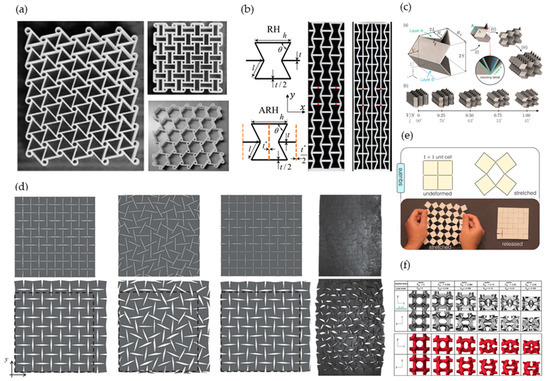
Figure 1.
Literature review and classification of existing auxetic structures: e.g., (a) chiral [33], (b) re-entrant [34], (c) origami [35], (d) perforated [36], (e) rotating rigid [37], and (f) ‘Bucklicrystal’ [38].
The geometrical complexity of auxetic structures makes additive manufacturing technologies unavoidable for their creation. Harnessing additive manufacturing to produce auxetic structures is a natural choice due to their intrinsic geometrical complexity. Table 1 summarizes the types of auxetic structures with the corresponding additive manufacturing technology and the materials used for their creation. In addition to polymer 3D printing, metal additive manufacturing technologies were incorporated to produce auxetic cellular structures [8,39,40,41].

Table 1.
Summary of different types of auxetic structures with corresponding additive manufacturing technology and materials used for their creation [42].
2. Simulation-Driven Parametric Design of Auxetic Structures
Based on the various existing auxetic patterns studied in the literature and their mechanical performance [43], a tetra-petal star-shaped unit cell (Figure 1) [44,45,46] was selected for the design and investigation in this study due to its symmetry and mechanical performance. The auxetic response of petal structures is attributed to a hinge and elastic support system similar to the response of star shape structures, with the advancement of avoiding sharp edges, which lead to stress concentrations and discontinuities during production under additive manufacturing technologies. Furthermore, tetra-petal structures exhibit an enhanced auxetic response compared to tri- and hexa-petal structures, and this behavior is strongly dependent on petal geometrical characteristics, form, and size.
Following the selection of the unit cell form, a numerical parameter study was conducted by varying certain geometrical features of the unit cells, including the angles of petals and between petals, the distance of the base strut from center, and the petal radius and the strut thickness, as shown in Figure 2. Twelve (12) variations of the tetra-petal unit cell were used to explore the lowest Poisson’s ratio that these unit cells could exhibit under compression loads, starting with two different polymers: polylactic acid (PLA) and thermoplastic polyurethane (TPU), which represent the high and low Young’s moduli classes, respectively. Number (8) was the initial design configuration of the tetra-petal unit-cell and is used as a reference. All unit cells exhibited effective Poisson’s ratios that are independent of the generated equivalent strains, i.e., they maintain their auxetic behavior independently from the material’s strain. For the case of the elastomer material, ν = −0.6 was achieved, while for the case of a hard polymer, ν = −0.4 was observed (Figure 3). For both cases, a finite element analysis was conducted, in which symmetry conditions were applied on the bottom and left surfaces of the unit cell, roller boundary conditions on the rear face, and vertical displacement on the upper face. The hard polymer was modeled as von Mises plastic material and the soft polymer as hyperelastic Mooney–Rivlin material (Table 2).
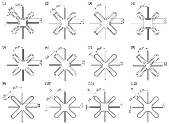
Figure 2.
Twelve (12) geometrical configurations of tetra-petal unit cells with varying angles of petals and between petals, distance of the base strut from center, petal radius and strut thickness, with unit cell (8) used as reference.
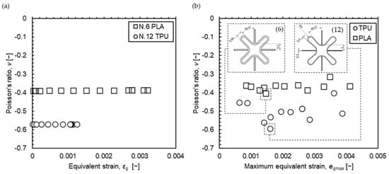
Figure 3.
(a) Calculated Poisson’s ratio of the auxetic unit cell independent of the equivalent strains by varying compression force in the linear regions for hard polymer (PLA) and elastomer (TPU); (b) calculated Poisson’s ratio for twelve (12) unit cells, geometrical variations, and selection of the two optimum configurations for PLA (number 6) and TPU (number 12).
Table 2.
Material properties used for the FE analysis of unit cells: Von Mises plastic material for hard polymer (PLA) and hyperelastic Mooney–Rivlin material for soft polymer (TPU).
3. Fabrication of Prototypes Sample by Means of 3D Printing
After the identification of the most appropriate geometrical variations of unit cells for the PLA and TPU polymer materials, 2D and 3D prototype samples of 3 × 3 unit cell systems were designed for further numerical and experimental investigations. For this purpose, two geometrical variations were favored: one for the 2D samples (Figure 4) and a similar one for the 3D samples (Figure 5) to allow for a direct comparison between different materials for each of the 3D printing processes. Samples were additively manufactured through FDM (2D samples) and SLS (3D samples) technologies. The proposed auxetic systems were created out of the following materials: PLA, PET, TPU through FDM process, and PA12, Duraform Flex® through powder bed fusion (PBF). Table 3 summarizes the various types of the manufactured auxetic samples used for experimental investigation in terms of their auxetic properties under compression.
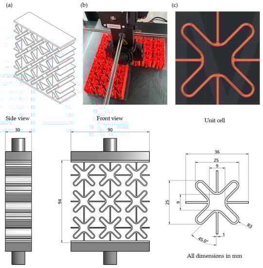
Figure 4.
(a) CAD of the 2D auxetic samples in different views; (b) creation of 2D samples by means of the FDM process; and (c) dimensional details of unit cells.
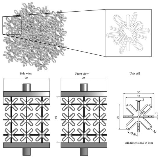
Figure 5.
CAD of the 3D auxetic samples in different views and dimensional details of unit cells.
Table 3.
Auxetic sample types with different materials and 3D printing method.
First, prototype samples of 2D auxetic systems were planned with the same number of unit cells (3 × 3). Three specimens were produced for each selected material (PLA, PET, TPU) using the fused deposition modeling (FDM) technique by means of 3D-printer Raise3D Pro2 Plus. The layer height selected to manufacture these parts was set to 0.2 mm, and the infill percentage was kept to 100%. Table 4 lists the process parameters of the FDM process. All specimens were manufactured along the z-direction, as illustrated in Figure 4, to refrain from using supports with a total size of 90 × 94 × 30 mm.
Table 4.
Process parameters for the FDM process with Raised 3D Pro2 Plus Dual Extruder.
In a similar fashion, two 3D samples with identical geometrical features were fabricated by means of powder bed fusion of polymers with two different materials. The PA12 sample was fabricated on an EOS P 396 SLS machine, while the Duraform FLEX sample was fabricated on a DTM Sinterstation 2500 Plus. The geometrical features of the 3D samples are shown in Figure 5, while the process parameters for the SLS processes are provided in Table 5 and Table 6.
Table 5.
Process parameters for SLS process with PA12 powder (nylon).
Table 6.
Process parameters for SLS process with Duraform Flex powder (rubber).
4. Experimental Mechanical Testing of 3D Printed Auxetic Structures
4.1. Experimental Setup
The sample prototypes created with 3D printing were experimentally tested under compression loading to investigate their auxetic response. All samples were characterized using a universal uniaxial compression tester with a strain rate of 0.04 s−1. Figure 6 shows the experimental setup for the compression testing. The force response during compression was captured with a force sensor as a function of the displacement of the hydraulic pressing punch, which was measured with a linear potentiometer. The measurements were captured by means of a data acquisition system, and the experiment was repeated three times for each auxetic sample type to ensure the repeatability of the recorded measurements.
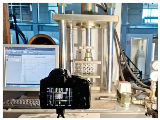
Figure 6.
Experimental setup for compression testing of auxetic samples.
4.2. Experimental Results
Figure 7 illustrates the force-displacement measurements for PLA, PET, TPU materials made by FDM and PA12 material by means of PBF. All four materials showed strong reproducibility. The Duraform Flex rubber 3D sample made by SLS demonstrated only minor force response (less than 2 N) due to very low overall stiffness. Since the measuring accuracy of the available force sensor was unable to capture forces of that range, the results for this material are omitted.
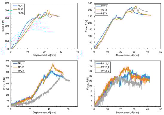
Figure 7.
Experimental measurements of force vs. displacements on auxetic samples.
The experimental study for the 2D auxetic geometries has shown that PLA samples provide the highest stiffness and force response, due to their high elastic modulus, compared to the other materials tested in this experiment. The experiments showed that between 15 mm and 20 mm of travelled compression distance of punch, the FDM 2D samples (PLA, PET, and TPU) produced an increase in the gradient. This elevated stiffness in samples was caused by the contact of the unit cells in the vertical direction during compression. In PLA and PET, the contact took place after the plastic deformation, while for TPU, the contact occurred in the elastic region of the auxetic samples due to the considerably lower Young’s Modulus. The SLS 3D auxetic sample made of PA12 powder indicates that lower levels of stiffness were due to the overall lower utilization of material, as illustrated in Figure 5 compared to the FDM 2D samples (Figure 4). The maximum force measured on the samples follows a trend comparable to the stiffness. This can be justified in a similar manner as the stiffness according to the mechanical properties and the overall geometry configuration between the 2D and 3D auxetic samples. The auxeticity was derived by the observed shrinkage only in the transverse x-direction for the 2D samples over the displacements in the loading z-direction, whereas the shrinkage that occurred in both the transverse plane x- and y-directions was used for obtaining the auxeticity of the 3D samples. Here it is worth mentioning that for all samples, the loading z-direction concurs with the building direction of the 3D printing processes for both FDM and SLS. The lower Poisson’s ratio estimated for the 3D sample compared to the 2D samples can be explained by the 3D nature of the sample and the fact that auxeticity occurred only in one transverse direction (x-direction) for the 2D samples, while shrinkage was observed in both of the plane directions x and y for the 3D probes. Table 7 summarizes the results on the average stiffness and maximum force recorded during the experiments, as well as the average resulting Poisson’s ratios for each auxetic sample. The average Poisson’s ratio for the 2D samples was obtained using the measured length reduction in the transverse x-direction during loading of the three samples for each material. Nevertheless, the average Poisson’s ratio for the 3D auxetic sample was calculated by means of the captured shrinkage in both transverse x- and y-directions with respect to the axial loading direction for three samples. A detailed auxetic response variation as a function of the strains for each sample was captured by image analysis and is illustrated in Figure 8.
Table 7.
The results of the average stiffness and average maximum force for the auxetic samples compared to the bulk mechanical properties of filament and powder materials.
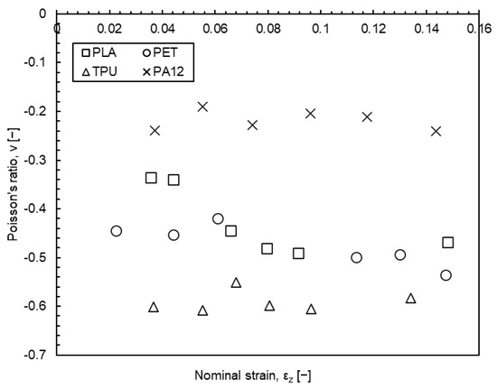
Figure 8.
Poisson’s ratio variation as a function of strains captured by image analysis of each sample at different displacements.
The above experimental results are used to evaluate the FE models, which are defined to replicate the compression tests of the auxetic samples and to allow for the determination of the auxeticity, i.e., Poisson’s ratio, of the samples based on the geometrical features and the material, as presented in the next section.
5. Numerical FE Modelling of Auxetic Systems’ Mechanical Behavior
Using the experimental testing results presented in Section 4 as a reference, finite element models were defined as a means of replicating the auxetic response of the fabricated samples. For this purpose, the 2D auxetic system with PLA and the 3D auxetic system with PA12 were modelled by means of implicit FE analysis, using the commercially available software ABAQUS/Standard of Dassault Systemes [47]. Details of the model geometry are shown in Figure 9, which consists of the auxetic sample, bottom plate, and top plates. The auxetic unit cell has identical geometrical characteristics as that of 3D printed models. For both cases (2D and 3D auxetic systems), the samples were meshed with the element C3D8R (an 8-node linear brick, reduced integration), and the two plates were simulated using discrete rigid surfaces with a reference point at their center. A mesh sensitivity analysis was performed to ensure that the simulations’ results were insensitive to the mesh size (convergence study). The auxetic sample was modeled as an elastic-perfectly plastic material (von Mises) by defining its elastic modulus , Poisson’s ratio ν, and yield point Y values, based on the properties of PLA and PA12 taken from the literature for FDM and SLS processing, respectively [48,49]. General contact conditions were defined between the two plates and the sample, ensuring an accurate calculation of contact stresses at each node. The contact between them introduces moving boundary conditions, which are often discontinuous, and solving the contact requires iterations for updating the model stiffness at every load increment. The contact formulation includes the use of a constrained enforcement method for the pair surfaces of the master (plates)–slave (auxetic sample) and accounts for finite strain, rotations, and sliding. Furthermore, the reference point of the top plate was subjected to a displacement load along the z-direction, while all degrees of freedom of the reference point of the bottom plate were fixed. Regarding all of the simulated studies, it is assumed that the loading rate is slow enough such that static friction can securely model the interface response. The force–displacement curve was calculated by defining the vertical punch compression motion as a function of time-step and the reaction forces at the bottom plate. The FE analysis was conducted for a compressive deformation for which no contact or self-contact occurred between or within unit cells of the auxetic systems.
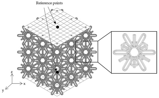
Figure 9.
FE mesh and model setup of the 3D auxetic sample.
The rendered simulation results for the two auxetic systems are presented in Figure 10 and Figure 11. The calculated deformed shape for the 2D auxetic system with PLA (left) as well as for the 3D auxetic system with PA12 (right) demonstrated alignment with the experimental results for progressive compression displacements with a maximum deviation less than 5%. It is also important to explain that the material yield strength did not exceed up to this level of compression and that the commencement of a non-linear behavior captured at the top of the force–displacement curve in Figure 11a is attributed to the buckling effect of the struts with increasing deformation.
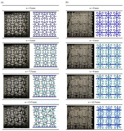
Figure 10.
Comparison of FE calculated deformed shapes with experimental images for progressive compression deformation of (a) the 2D auxetic system with PLA and (b) the 3D auxetic system with PA12.
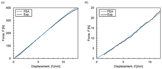
Figure 11.
Force–displacement diagram of the FE calculations compared to experimental measurements for (a) the 2D auxetic system with PLA and (b) the 3D auxetic system with PA12.
6. Discussion and Conclusions
The presented design work on auxetic tetra-petal structures initially aimed to identify the most suitable unit cells that exhibit the highest Poisson’s ratio for specific polymers. Furthermore, based on the selected unit cells, the proposed configurations were fabricated with various 3D printable polymers and evaluated experimentally and numerically. Design aspects for additive manufacturing, 3D printing processes, and materials, as well as characterization tools, were utilized in this study to demonstrate the potentials of 3D printing techniques towards further improvement of the auxetic behavior of such auxetic systems. A Poisson’s ratio increase reaching 28% for hard polymers, i.e., PLA, for the best performing configuration (6) and up to 47% for elastomers, i.e., TPU, for the best performing configuration (12) compared to the reference unit cell configuration (8) of Figure 2 was initially demonstrated by means of FE calculations, by selecting the appropriate geometrical features, as shown in Figure 3b. Furthermore, the 3D printed FDM samples with PLA, PET, and TPU reached Poisson’s ratios of ν = −0.43, −0.47, and −0.59, respectively, as measured from experimental compression tests (Table 7). Hereby, an actual final Poisson’s ratio improvement of 36% for PLA samples was achieved compared to the FE calculated Poisson’s ratio of the reference unit cell (8). On the other hand, the final measured Poisson’s ratio on TPU samples reached the same Poisson’s ratio with the FE simulated unit cell (12). In addition, the possibility offered by powder bed fusion to evolve the auxetic geometry in further directions, thus creating 3D auxetic patterns, was presented demonstrating the auxeticity of ν = −0.22 in two transverse directions, i.e., in x- and y-direction. Finally, the introduced FE models reproduced the auxetic performance of the tested 2D and 3D samples in the elastic region with only marginal deviation compared to experiments. Noticeable deviation is observed in case of the 2D samples at higher deformation due to the buckling effect of the struts.
7. Outlook and Future Research
The current research work has shown promising results, and certain topics have been identified which require further research. More specifically, future research is needed in the context of enhancing the obtained results:
- Use the rendered knowledge for the 3D printing of auxetic structures with metallic alloys by means of powder bed fusion for lightweight energy absorption applications and for human bone implants with adapted stiffness properties;
- Implement material properties in the finite element model derived from the experimental mechanical characterization of samples created by the particular 3D printing process, i.e., FDM or SLS, with specific process parameters, in order to replicate irregularities and possible anisotropy in the real built-up material;
- Enhance the finite element model definition to include contact conditions between and within the auxetic unit cells, plasticity behavior, and fracture criteria;
- Perform experimental testing at higher impact speeds to characterize the auxetic behavior at high strain rates.
Author Contributions
Conceptualization, D.P. and L.P.; methodology, D.P. and L.P.; software, D.P. and L.P.; validation, D.P., S.A., F.S., F.V., O.J. and L.P.; formal analysis, D.P., S.A., F.S., F.V. and O.J.; investigation, D.P., S.A. and L.P.; resources, D.P., S.A., F.S., F.V., O.J. and L.P.; data curation, D.P. and S.A.; writing—original draft preparation, D.P., S.A., F.S., F.V., O.J. and L.P.; writing—review and editing, D.P. and L.P.; visualization, D.P. and S.A.; supervision, L.P.; project administration, D.P., S.A. and L.P.; funding acquisition, D.P, S.A., O.J. and L.P. All authors have read and agreed to the published version of the manuscript.
Funding
This research was funded by the European Commission’s Horizon 2020 research and innovation program under the grant number 768775.
Acknowledgments
This research was funded in the frame of the AMable Project by the European Commission’s Horizon 2020 research and innovation program under the Grant agreement 768775. Project website: http://www.amable.eu (accessed on 30 October 2021).
Conflicts of Interest
The authors declare no conflict of interest.
References
- Imbalzano, G.; Linforth, S.; Ngo, T.D.; Lee, P.V.S.; Tran, P. Blast resistance of auxetic and honeycomb sandwich panels: Comparisons and parametric designs. Compos. Struct. 2018, 183, 242–261. [Google Scholar] [CrossRef]
- Castanie, B.; Bouvet, C.; Ginot, M. Review of composite sandwich structure in aeronautic applications. Compos. Part C Open Access 2020, 1, 100004. [Google Scholar] [CrossRef]
- Tarlochan, F. Sandwich Structures for Energy Absorption Applications: A Review. Materials 2021, 14, 4731. [Google Scholar] [CrossRef]
- Hunady, R. A Sensitivity Analysis of the Dynamic Behavior of Aluminium Honeycomb Sandwich Panels. Am. J. Mech. Eng. 2016, 4, 236–240. [Google Scholar]
- Strek, T.; Jopek, H.; Nienartowicz, M. Dynamic response of sandwich panels with auxetic cores. Phys. Status Solidi 2015, 252, 1540–1550. [Google Scholar] [CrossRef]
- Xiao, D.; Chen, X.; Li, Y.; Wu, W.; Fang, D. The structure response of sandwich beams with metallic auxetic honeycomb cores under localized impulsive loading-experiments and finite element analysis. Mater. Des. 2019, 176, 107840. [Google Scholar] [CrossRef]
- Photiou, D.; Prastiti, N.; Sarris, E.; Constantinides, G. On the conical indentation response of elastic auxetic materials: Effects of Poisson’s ratio, contact friction and cone angle. Int. J. Solids Struct. 2016, 81, 33–42. [Google Scholar] [CrossRef]
- Kolken, H.M.A.; Zadpoor, A.A. Auxetic mechanical metamaterials. RSC Adv. 2017, 7, 5111–5129. [Google Scholar] [CrossRef]
- Foster, L.; Peketi, P.; Allen, T.; Senior, T.; Duncan, O.; Alderson, A. Application of Auxetic Foam in Sports Helmets. Appl. Sci. 2018, 8, 354. [Google Scholar] [CrossRef]
- Duncan, O.; Shepherd, T.; Moroney, C.; Foster, L.; Venkatraman, P.; Winwood, K.; Allen, T.; Alderson, A. Review of Auxetic Materials for Sports Applications: Expanding Options in Comfort and Protection. Appl. Sci. 2018, 8, 941. [Google Scholar] [CrossRef]
- Imbalzano, G.; Tran, P.; Ngo, T.D.; Lee, P.V. Three-dimensional modelling of auxetic sandwich panels for localised impact resistance. J. Sandw. Struct. Mater. 2017, 19, 291–316. [Google Scholar] [CrossRef]
- Guo, C.; Zhao, D.; Liu, Z.; Ding, Q.; Gao, H.; Yan, Q.; Sun, Y.; Ren, F. The 3D-Printed Honeycomb Metamaterials Tubes with Tunable Negative Poisson’s Ratio for High-Performance Static and Dynamic Mechanical Properties. Materials 2021, 14, 1353. [Google Scholar] [CrossRef]
- Dudek, K.K.; Attard, D.; Gatt, R.; Grima-Cornish, J.N.; Grima, J.N. The Multidirectional Auxeticity and Negative Linear Compressibility of a 3D Mechanical Metamaterial. Materials 2020, 13, 2193. [Google Scholar] [CrossRef] [PubMed]
- Fu, Y.; Yu, T.; Wang, X. Study on a Chiral Structure with Tunable Poisson’s Ratio. Materials 2021, 14, 3338. [Google Scholar] [CrossRef]
- Photiou, D. Computational Modeling of Nanoindentation on Emerging Materials: Auxetics, Hard Thin Films and Cohesive-Frictional Solids. Ph.D. Thesis, Cyprus University of Technology, Limassol, Cyprus, 2019. [Google Scholar]
- Bilski, M.; Pigłowski, P.M.; Wojciechowski, K.W. Extreme Poisson’s Ratios of Honeycomb, Re-Entrant, and Zig-Zag Crystals of Binary Hard Discs. Symmetry 2021, 13, 1127. [Google Scholar] [CrossRef]
- Gibson, L.J.; Ashby, M.F. Cellular Solids; Cambridge University Press: Cambridge, UK, 1997; ISBN 9781139878326. [Google Scholar]
- Lakes, R. Deformation mechanisms in negative Poisson’s ratio materials: Structural aspects. J. Mater. Sci. 1991, 26, 2287–2292. [Google Scholar] [CrossRef]
- Wojciechowski, K.W. Constant thermodynamic tension Monte Carlo studies of elastic properties of a two-dimensional system of hard cyclic hexamers. Mol. Phys. 1987, 61, 1247–1258. [Google Scholar] [CrossRef]
- Wojciechowski, K.W. Two-dimensional isotropic system with a negative poisson ratio. Phys. Lett. A 1989, 137, 60–64. [Google Scholar] [CrossRef]
- Wojciechowski, K.W. Non-chiral, molecular model of negative Poisson ratio in two dimensions. J. Phys. A Math. Gen. 2003, 36, 11765–11778. [Google Scholar] [CrossRef]
- Grima, J.N.; Evans, K.E. Auxetic behavior from rotating squares. J. Mater. Sci. Lett. 2000, 19, 1563–1565. [Google Scholar] [CrossRef]
- Alderson, A.; Evans, K.E. Rotation and dilation deformation mechanisms for auxetic behaviour in the $α$-cristobalite tetrahedral framework structure. Phys. Chem. Miner. 2001, 28, 711–718. [Google Scholar] [CrossRef]
- Grima, J.N.; Evans, K.E. Auxetic behavior from rotating triangles. J. Mater. Sci. 2006, 41, 3193–3196. [Google Scholar] [CrossRef]
- Grima, J.N.; Chetcuti, E.; Manicaro, E.; Attard, D.; Camilleri, M.; Gatt, R.; Evans, K.E. On the auxetic properties of generic rotating rigid triangles. Proc. R. Soc. A Math. Phys. Eng. Sci. 2012, 468, 810–830. [Google Scholar] [CrossRef]
- Grima, J.N.; Gatt, R.; Ellul, B.; Chetcuti, E. Auxetic behaviour in non-crystalline materials having star or triangular shaped perforations. J. Non-Cryst. Solids 2010, 356, 1980–1987. [Google Scholar] [CrossRef]
- Grima, J.N.; Alderson, A.; Evans, K.E. Negative Poisson’s ratios from rotating rectangles. Comput. Methods Sci. Technol. 2004, 10, 137–145. [Google Scholar] [CrossRef]
- Grima, J.N.; Gatt, R.; Farrugia, P.-S. On the properties of auxetic meta-tetrachiral structures. Phys. Status Solidi 2008, 245, 511–520. [Google Scholar] [CrossRef]
- Grima, J.N.; Gatt, R.; Alderson, A.; Evans, K.E. On the origin of auxetic behaviour in the silicate α-cristobalite. J. Mater. Chem. 2005, 15, 4003. [Google Scholar] [CrossRef]
- Grima, J.N.; Manicaro, E.; Attard, D. Auxetic behaviour from connected different-sized squares and rectangles. Proc. R. Soc. A Math. Phys. Eng. Sci. 2011, 467, 439–458. [Google Scholar] [CrossRef]
- Narojczyk, J.W.; Wojciechowski, K.W. Elastic properties of degenerate f.c.c. crystal of polydisperse soft dimers at zero temperature. J. Non-Cryst. Solids 2010, 356, 2026–2032. [Google Scholar] [CrossRef]
- Hoover, W.G.; Hoover, C.G. Searching for auxetics with DYNA3D and ParaDyn. Phys. Status Solidi 2005, 242, 585–594. [Google Scholar] [CrossRef][Green Version]
- Alderson, A.; Alderson, K.L.; Attard, D.; Evans, K.E.; Gatt, R.; Grima, J.N.; Miller, W.; Ravirala, N.; Smith, C.W.; Zied, K. Elastic constants of 3-, 4- and 6-connected chiral and anti-chiral honeycombs subject to uniaxial in-plane loading. Compos. Sci. Technol. 2010, 70, 1042–1048. [Google Scholar] [CrossRef]
- Li, X.; Wang, Q.; Yang, Z.; Lu, Z. Novel auxetic structures with enhanced mechanical properties. Extrem. Mech. Lett. 2019, 27, 59–65. [Google Scholar] [CrossRef]
- Harris, J.A.; McShane, G.J. Metallic stacked origami cellular materials: Additive manufacturing, properties, and modelling. Int. J. Solids Struct. 2020, 185–186, 448–466. [Google Scholar] [CrossRef]
- Grima, J.N.; Mizzi, L.; Azzopardi, K.M.; Gatt, R. Auxetic Perforated Mechanical Metamaterials with Randomly Oriented Cuts. Adv. Mater. 2016, 28, 385–389. [Google Scholar] [CrossRef] [PubMed]
- Rafsanjani, A.; Pasini, D. Bistable auxetic mechanical metamaterials inspired by ancient geometric motifs. Extrem. Mech. Lett. 2016, 9, 291–296. [Google Scholar] [CrossRef]
- Babaee, S.; Shim, J.; Weaver, J.C.; Chen, E.R.; Patel, N.; Bertoldi, K. 3D Soft Metamaterials with Negative Poisson’s Ratio. Adv. Mater. 2013, 25, 5044–5049. [Google Scholar] [CrossRef]
- Kolken, H.M.A.; Garcia, A.F.; Du Plessis, A.; Rans, C.; Mirzaali, M.J.; Zadpoor, A.A. Fatigue performance of auxetic meta-biomaterials. Acta Biomater. 2021, 126, 511–523. [Google Scholar] [CrossRef]
- Khan, S.Z.; Masood, S.H.; Cottam, R. Mechanical properties in tensile loading of H13 re-entrant honeycomb auxetic structure manufactured by direct metal deposition. MATEC Web Conf. 2015, 34, 01004. [Google Scholar] [CrossRef]
- Meena, K.; Singamneni, S. A new auxetic structure with significantly reduced stress concentration effects. Mater. Des. 2019, 173, 107779. [Google Scholar] [CrossRef]
- Wang, Z.; Luan, C.; Liao, G.; Liu, J.; Yao, X.; Fu, J. Progress in Auxetic Mechanical Metamaterials: Structures, Characteristics, Manufacturing Methods, and Applications. Adv. Eng. Mater. 2020, 22, 2000312. [Google Scholar] [CrossRef]
- Zhang, J.; Lu, G.; You, Z. Large deformation and energy absorption of additively manufactured auxetic materials and structures: A review. Compos. Part B Eng. 2020, 201, 108340. [Google Scholar] [CrossRef]
- Wang, Z.-P.; Poh, L.H.; Dirrenberger, J.; Zhu, Y.; Forest, S. Isogeometric shape optimization of smoothed petal auxetic structures via computational periodic homogenization. Comput. Methods Appl. Mech. Eng. 2017, 323, 250–271. [Google Scholar] [CrossRef]
- Koutsianitis, P.I.; Tairidis, G.K.; Stavroulakis, G.E. Shunted piezoelectric patches on auxetic microstructures for the enhancement of band gaps. Arch. Appl. Mech. 2021, 91, 739–751. [Google Scholar] [CrossRef]
- Koutsianitis, P.I.; Tairidis, G.K.; Drosopoulos, G.A.; Stavroulakis, G.E. Conventional and star-shaped auxetic materials for the creation of band gaps. Arch. Appl. Mech. 2019, 89, 2545–2562. [Google Scholar] [CrossRef]
- Dassault Systèmes. ABAQUS: Theory Manual; Dassault Systèmes Simulia Corp.: Providence, RI, USA, 2011; Available online: http://130.149.89.49:2080/v6.11/pdf_books/THEORY.pdf (accessed on 30 October 2021).
- Zhao, Y.; Chen, Y.; Zhou, Y. Novel mechanical models of tensile strength and elastic property of FDM AM PLA materials: Experimental and theoretical analyses. Mater. Des. 2019, 181, 108089. [Google Scholar] [CrossRef]
- Lindberg, A.; Alfthan, J.; Pettersson, H.; Flodberg, G.; Yang, L. Mechanical performance of polymer powder bed fused objects—FEM simulation and verification. Addit. Manuf. 2018, 24, 577–586. [Google Scholar] [CrossRef]


Publisher’s Note: MDPI stays neutral with regard to jurisdictional claims in published maps and institutional affiliations. |
© 2021 by the authors. Licensee MDPI, Basel, Switzerland. This article is an open access article distributed under the terms and conditions of the Creative Commons Attribution (CC BY) license (https://creativecommons.org/licenses/by/4.0/).