


Abstract
In helicopter rotor systems, effective suppression of lead–lag vibration requires dampers with reliable load transfer, appropriate stiffness matching, tunable damping, and efficient energy dissipation. However, conventional lead–lag dampers often suffer from limited stiffness–damping adjustability and sealing-related constraints. Here, we developed a magnetorheological fluid elastomeric (MRFE) damper by integrating magnetorheological fluid with a rubber elastomer. An elastomer system with a target shear modulus of 0.72 MPa was obtained through systematic design of the rubber formulation, rubber–metal bonding, and vulcanization process. Dynamic characterization showed that the dissipated energy increased markedly with amplitude but only slightly with frequency, whereas applied current exerted the strongest influence on the MRFE response. As the current increased from 0 to 1.5 A, the dissipated energy, effective stiffness, and equivalent damping coefficient increased by 1901.5%, 491.0%, and 961.1%, respectively. The zero-current effective stiffness of 0.443 kN/mm closely matched the required baseline stiffness of 0.44 kN/mm. For inverse current prediction, the improved Transformer model with hyperparameters optimized using PSO achieved a 72.04% lower RMSE than the differential evolution-assisted one-dimensional long short-term memory (DE-1DLSTM) model. These results suggest the potential of the MRFE for stiffness-matched support, controllable energy dissipation, and data-driven current prediction in rotor lead–lag vibration mitigation.
1. Introduction
Helicopter rotor systems are high-speed rotating flexible structures whose dynamic responses are governed by aerodynamic loads, centrifugal forces, inertial forces, hub constraints, and fuselage vibrations [1]. Under critical operating conditions, such as takeoff, landing, startup, and shutdown, non-uniform aerodynamic loading and inertial imbalance may induce lead–lag vibration within the rotor plane. Insufficient damping of this vibration can intensify blade–fuselage coupling and trigger ground resonance under specific rotor speeds and support conditions [2,3]. Therefore, lead–lag dampers are essential for suppressing in-plane rotor vibration to reduce ground-resonance risk as well as to improve helicopter operational safety [4].
Conventional helicopter rotor dampers mainly include friction dampers, hydraulic dampers, elastomeric dampers, and fluid-elastic dampers [5,6,7,8]. Fluid-elastic dampers provide elastic support through rubber elastomers and dissipate vibration energy through fluid flow and material hysteresis. Although they offer compact structure, high load-carrying capacity, and good reliability, their passive damping characteristics are difficult to adapt to varying flight conditions [3]. High damping is required during startup and shutdown to suppress lead–lag vibration, whereas excessive damping during steady flight may increase hub loads and accelerate structural fatigue [9]. Therefore, advanced dampers with load-bearing capability, stiffness matching, and tunable energy-dissipation performance are required.
Magnetorheological fluid (MRF) is a smart material whose rheological properties can be rapidly and reversibly regulated by an external magnetic field. Owing to its fast response, low power consumption, and fail-safe characteristics, MRF has begun to attract widespread attention for semi-active vibration control in recent years [10]. By combining the field-dependent rheological response of MRF with the elastic support and viscoelastic energy dissipation of rubber elastomers, magnetorheological fluid elastomeric dampers (MRFEs) can provide load-bearing support, vibration isolation, energy dissipation, and tunable damping in a compact structure. Related hybrid magnetorheological systems, including MRF–MRE configurations and MRF–elastomer structures, have been explored for vibration control, sensing, and actuation [11,12,13,14]. For rotor lead–lag applications in particular, MRF-based elastomeric damping structures have demonstrated the feasibility of combining elastic support with controllable damping. Jiang et al. [15] developed a compact MRFE and verified the magnetic-field-dependent modulation of its damping force through dynamic experiments. Hu and Wereley [16] investigated hybrid MR fluid–elastomeric lag dampers for helicopter stability augmentation. Jin et al. [17] proposed an MR fluid–elastomer damper for engine-mount applications and subsequently investigated its dynamic performance through experiments and coupled magnetic–fluid–structural simulations [18]. The later study reported increases of 20.6% in in-phase stiffness and 81.6% in equivalent damping as the applied current increased from 0 to 1.6 A. Quantitative studies of MRFE prototypes for helicopter applications have also demonstrated substantial controllable performance. Ngatu et al. [19] developed a full-scale MRFE helicopter lag damper and reported a damping increase of approximately 200% under low-amplitude lag-motion conditions. Kothera et al. [20] further investigated a semiactive fluid-elastomeric helicopter lag damper and reported an approximately 80–200% increase in energy dissipation over the investigated displacement-amplitude range. These results demonstrate that existing MRFE prototypes can achieve appreciable current-dependent regulation of stiffness, damping, and energy-dissipation performance, although the achievable regulation ranges vary with device configuration and operating conditions. Nevertheless, their practical implementation in rotor systems requires the concurrent achievement of reliable elastic support, appropriate stiffness matching, effective energy dissipation, and stable field-tunable dynamic performance.
Existing studies have mainly focused on the sedimentation stability [21,22], rheological characterization [23], structural design and dynamic testing of the dampers [24,25]. However, the relationships among material-level elastomer design, rubber–metal interfacial integrity, vulcanization quality, stiffness–damping matching, and response prediction remain insufficiently established. In particular, for thick rubber elastomer components, non-uniform heat transfer during vulcanization may lead to spatial variations in curing state, thereby affecting stiffness stability, damping performance, and service reliability [26,27,28]. Temperature monitoring, bubble-point testing, sectional dissection, and layer-by-layer mechanical testing can determine vulcanization conditions, but these experimental methods are time-consuming, costly, and limited in repeatability [29]. Finite element thermo-vulcanization simulation enables the prediction of transient temperature evolution and curing uniformity in rubber components, providing a computational basis for vulcanization-process optimization and manufacturing consistency [30]. Beyond process optimization, accurate response prediction is required to characterize the MRFE behavior. The force output of rotor lead–lag dampers depends on displacement, velocity, applied current, rubber viscoelasticity, and MRF hysteresis, resulting in nonlinear and hysteretic responses [9]. Conventional linear stiffness–damping models are inadequate for such responses, while purely data-driven models may lack robustness under varying conditions [31]. With the advancement of artificial intelligence technology, back propagation (BP) neural network [32,33,34] and long short-term memory (LSTM) models [35] have been successfully applied to the current control of MRF dampers. However, the gradient-based BP neural network suffers from slow convergence and tends to fall into local optimal solutions [36]. When dealing with long sequences, LSTM models based on recurrent architectures often suffer from vanishing gradients and difficulties in capturing long-term dependencies [37]. The Transformer architecture, proposed by Vaswani et al. [38], eliminates recurrent and convolutional operations and employs positional encoding, multi-head attention, residual connections, and layer normalization [39]. Through the self-attention mechanism, the Transformer can efficiently capture global dependencies within input sequences [40]. For the short-duration periodic MRFE signals considered in this study, self-attention is employed to capture interactions among sampling points within each short sequence rather than specifically for long-sequence modelling. Although BP neural networks and LSTM models have been widely used for nonlinear response prediction, they still exhibit inherent limitations, whereas the Transformer architecture has rarely been applied to the dynamic response characterization of magnetorheological dampers.
In this study, based on an MRFE configuration previously proposed by our group [15], a development–characterization–prediction framework was established to reveal how material design, interfacial bonding, and manufacturing uniformity govern stiffness–damping matching, hysteretic energy dissipation, and current-regulated MRFE performance. Rotor-level stiffness requirements were translated into elastomer formulation optimization, rubber–metal bonding design, and thermo-vulcanization control, providing the material and manufacturing basis for prototype development. The fabricated MRFE was dynamically characterized to quantify its energy-dissipation capability, stiffness response, damping behavior, and magnetic-field tunability. An improved Transformer model with hyperparameters optimized using PSO was further developed to predict the required current under multiple operating conditions, thereby supporting data-driven regulation of the damper mechanical response.
2. Elastomer Design for Energy-Dissipating MRFE
2.1. Rotor Requirements and Elastomer Stiffness Target
The dynamic response of the magnetorheological fluid elastomeric damper is governed by the coupling between the magnetically tunable dissipation of the magnetorheological fluid (MRF) and the elastic energy-storage capability of the rubber elastomer. Helicopter rotor lead–lag vibration imposes a periodic mechanical-energy input on the damping path, during which vibration energy is repeatedly transferred from the rotor hub to the MRFE. Accordingly, the damper is designed not merely to attenuate displacement and force fluctuations, but to regulate the pathway through which mechanical energy is transmitted, temporarily stored in the elastomer, and irreversibly dissipated through magnetically tunable damping.
In the proposed damper, the MRF is responsible for field-regulated viscous resistance and yield-force generation, whereas the rubber elastomer provides baseline elastic support, restoring force, displacement transmission, and sealing. The stiffness, deformation capacity, and cyclic stability of the elastomer therefore define the fundamental mechanical boundary conditions for energy transfer within the MRFE. Insufficient elastomer stiffness may compromise the restoring and load-transfer capability of the damper, whereas excessive stiffness may increase hub loads and rubber–metal interfacial stress concentration, thereby limiting the deformation range available for effective vibration-energy dissipation. Therefore, the elastomer must be designed to satisfy rotor-level vibration-reduction requirements and to establish appropriate mechanical conditions for vibration-energy transfer, storage, and dissipation in the MRFE. Given the well-established field-dependent rheology and commercial maturity of MRFs, this study focuses on designing the elastomeric component of the MRFE to achieve the required stiffness compatibility and reliable mechanical energy transfer for rotor lead–lag damping. Establishing an appropriate elastomer stiffness target is therefore a prerequisite for subsequent material formulation and performance evaluation.
The parameter categories and physical definitions required for the stiffness back-calculation were selected with reference to published studies on rotor lead–lag dynamics [41]. The representative values reported in Ref. [41] are summarized in Table 1 solely to illustrate the relevant parameter types and their typical magnitudes, rather than being used as numerical inputs in the present calculations. Instead, rotor-specific values were independently specified for the system considered herein and are withheld because of project-related confidentiality restrictions. Using these system-specific inputs, the target elastomer stiffness was back-calculated to satisfy the prescribed lead–lag natural-frequency requirement.
Table 1.
Representative structural and dynamic parameters of the rotor model reported in Ref. [41].
Accordingly, the rotor-level dynamic requirement was converted into an equivalent stiffness criterion for the MRFE, thereby establishing a mechanical basis for the subsequent analysis of elastic energy storage and vibration-energy dissipation. Specifically, the target first lead–lag natural frequency () of the rotor blade was specified as one half of the rotor rotational speed (), as expressed in Equation (1) [41].
This frequency constraint was subsequently used to determine the additional angular stiffness () required from the MRFE. As expressed in Equation (2), the corresponding lead–lag dynamic relationship accounts for centrifugal stiffening, the rotational stiffness of the elastomeric bearing () and the additional angular stiffness contributed by the MRFE ().
Substitution of the frequency constraint in Equation (1) and the rotor-specific numerical inputs into Equation (2), followed by rearrangement, yielded the additional angular stiffness required from the MRFE . These numerical inputs correspond to the parameter categories illustrated in Table 1 but differ from the representative values reported therein, which were not used in the present calculation.
To establish a device-level design target, was subsequently converted into the equivalent translational stiffness of the MRFE (K′) based on the inter-blade installation geometry, as expressed in Equation (3).
where κ is the configuration coefficient associated with the inter-blade arrangement of the rotor hub MRFEs.
For the rotor-specific inputs adopted in this study, the frequency relation in Equation (1) corresponded to a target first lead–lag natural frequency of 1.73 Hz. Application of Equations (2) and (3) then yielded an equivalent translational stiffness requirement of 0.44 kN/mm for the MRFE. This value defines the device-level stiffness target for elastomer design and serves as a reference for subsequent stiffness matching and performance evaluation.
Figure 1a illustrates the configuration and working principle of the proposed MRFE, which consists of a magnetorheological damping unit arranged in parallel with a cylindrical rubber elastomer–metal assembly. In this configuration, the magnetorheological damping unit provides field-regulated energy dissipation, whereas the rubber elastomer–metal assembly supplies elastic support, restoring force, displacement transmission, and sealing. The magnetic outer cylinder of the damping unit is rigidly connected to the outer cylinder of the elastomer assembly, and the piston divides the internal chamber into two MRF-filled working chambers connected by an annular flow channel. Under lead–lag excitation, the piston-driven axial motion generates relative displacement between the inner and outer cylinders of the elastomer assembly, inducing shear deformation of the rubber elastomer and forming the elastic restoring force and temporary energy-storage path of the MRFE. Simultaneously, the resulting pressure difference between the two working chambers drives the MRF through the annular channel, where the transmitted vibration energy is dissipated through viscous flow resistance. By regulating the excitation current, the magnetic flux density in the flow channel can be adjusted, thereby increasing the yield stress and apparent viscosity of the MRF and producing a field-dependent yield-force component in addition to the viscous damping component. Therefore, the MRFE operates as a coupled elastic-storage and magnetically tunable energy-dissipation element, in which the rubber elastomer determines the baseline stiffness, deformation capacity, and load-transfer path, while the MRF enables controllable dissipation of the transmitted vibration energy. In this coupled energy-transfer and dissipation mechanism, the shear stiffness of the rubber elastomer becomes a critical design parameter, as it governs stiffness matching, elastic energy storage, stable mechanical-energy transmission, and the effectiveness of field-regulated damping within the MRFE.
Figure 1.
MRFE configuration and the preparation and testing of rubber elastomer–metal bonding specimens.
To quantify the contribution of the rubber elastomer to the overall stiffness of the MRFE, its shear deformation is further analyzed. Because of the radial variation in geometry, the shear strain and shear stress are non-uniformly distributed across the elastomer thickness. To describe this non-uniform shear field and to establish the link between elastomer geometry, stiffness, and elastic energy-storage capability, an equivalent radius (Req) was introduced. Based on the force equilibrium of a unit-height annular rubber layer, the shear force and deformation relationships can be expressed as Equation (4).
where F is the shear force per unit height; and are the shear strain and shear stress at the inner radius , respectively; and are the corresponding quantities at the outer radius ; and G* is the complex shear modulus of the elastomer. Based on Equation (4), the expression for the equivalent radius of the annular rubber elastomer can be derived as Equation (5).
The equivalent-radius formulation links the annular elastomer geometry to its shear load-transfer behavior. In the energy-oriented stiffness design of the MRFE, the storage modulus characterizes the recoverable elastic response of the rubber elastomer and thus determines its capacity for temporary elastic energy storage under cyclic lead–lag deformation. The equivalent translational stiffness K′ of the MRFE is therefore related to G′ through the annular shear geometry, as expressed in Equation (6).
By substituting the device-level stiffness requirement of the MRFE and the geometric parameters of the elastomer into Equation (6), the target storage modulus of the rubber elastomer can be determined. In the present design, the outer radius R2, inner radius R1, thickness d, and height L of the cylindrical rubber elastomer were selected as 30 mm, 18 mm, 12 mm, and 50 mm, respectively, yielding a target storage modulus of approximately 0.72 MPa. This modulus translates the equivalent translational stiffness requirement of 0.44 kN/mm into a material-level design criterion for the elastomer. More importantly, it defines the elastic foundation required for stiffness matching, recoverable energy storage, stable load transfer, and vibration-energy transmission within the MRFE. Therefore, the target modulus of 0.72 MPa was adopted as the primary criterion for subsequent elastomer formulation optimization, rubber–metal interfacial bonding design, vulcanization process development, and MRFE prototype fabrication.
2.2. Material and Processing Design
2.2.1. Rubber–Metal Interfacial Bonding Design
The rubber–metal interface plays a critical role in the coupled energy-transfer and dissipation mechanisms of the MRFE. In addition to providing structural continuity, it serves as a key pathway for transmitting cyclic mechanical energy induced by rotor excitation to the elastomer and the MRF damping unit. During operation, repeated shear deformation and localized stress concentrations can develop at the bonded interface. Inadequate interfacial bonding may therefore promote debonding, crack initiation, and rubber-layer delamination, disrupting mechanical-energy transfer and compromising the stability of hysteretic energy dissipation. These interfacial defects can ultimately degrade the vibration attenuation performance of the MRFE. Robust rubber–metal adhesion is thus essential for preserving elastic restoring capability, stable load transfer, sealing integrity, and overall structural reliability under cyclic lead–lag excitation. Accordingly, appropriate design of the rubber–metal bonding process is important for ensuring stable mechanical energy transfer, durable elastic support, and reliable overall performance of the MRFE. The bonding strength between the rubber elastomer and metal substrate was evaluated according to GB/T11211-2009 [42] (Determination of the Adhesion Strength between Vulcanized or Thermoplastic Rubber and Metal—Two-Plate Method). The bonded specimen consists of two parallel cylindrical metal blocks connected by an intermediate rubber layer, with the metal blocks having a thickness of 3.0 ± 0.1 mm and a diameter of 35.0–40.0 mm. To ensure dimensional accuracy, uniform rubber thickness, and consistent loading conditions during testing, a dedicated mold was designed for specimen fabrication. As shown in Figure 1b, the mold consists of upper, middle, and lower sections. The lower mold is used to position the lower metal cylinder, the middle mold defined the molding space of the rubber layer, and the upper mold applies molding pressure while maintaining the coaxial alignment of the two metal cylinders. To prevent secondary damage to the bonding interface during demolding, a specially designed extraction mechanism was developed, as illustrated in Figure 1c. The bonded specimen could be smoothly removed by gradually rotating the extraction knob, thereby minimizing additional disturbance to the rubber–metal interface after vulcanization. The fabrication of the rubber–metal bonded specimen is illustrated in Figure 1d, involving metal surface treatment, adhesive application, mold filling with rubber compound, and vulcanization molding. Prior to bonding, the metal surfaces were cleaned and roughened to remove contaminants and enhance interfacial activity. A primer and cover adhesive were then uniformly applied to form a continuous bonding layer. After partial curing of the adhesive, the rubber compound was placed between the upper and lower metal cylinders, followed by mold assembly and vulcanization at 143 °C and 5 MPa for 10 min. Upon completion of vulcanization, the bonded specimens were carefully removed using the extraction mechanism to preserve the integrity of the rubber–metal interface.
The interfacial bonding strength was measured using the dedicated fixture shown in Figure 1e. During testing, a uniformly distributed shear load perpendicular to the bonded interface was applied at a constant crosshead speed of 25 ± 5 mm/min until failure. The bonding strength was determined from the ratio of the maximum failure load to the bonded area. To identify a bonding process suitable for cyclic energy-transfer applications, the effects of surface pretreatment, adhesive system, and adhesive curing condition were systematically investigated. Specimens prepared using shot blasting and the ChemLok 205/220 adhesive system achieved a bonding strength of 0.8 MPa after adhesive curing at 60 °C for 1 h before vulcanization. Under the same curing condition, replacing the surface treatment and adhesive system with electrical discharge machining (EDM) and the 211/411 adhesive system increased the bonding strength to 3.4 MPa. Further adjustment of the adhesive curing parameters to 100 °C and 20 min increased the bonding strength to 6.8 MPa. The results demonstrate that rubber–metal bonding strength is highly dependent on surface activation, adhesive system, and adhesive curing condition. Specifically, the highest bonding strength of 6.8 MPa was obtained when EDM surface treatment was combined with the 211/411 adhesive system and adhesive curing at 100 °C for 20 min before vulcanization. The enhanced bonding strength provides a robust rubber–metal interface that supports effective load transfer within the MRFE. Accordingly, the developed bonding process provides a reliable manufacturing basis for subsequent MRFE prototype fabrication and dynamic characterization.
2.2.2. Formulation and Processing Parameter Design
To achieve the target shear modulus required for the MRFE, the rubber elastomer was systematically designed through matrix selection, vulcanization control, and carbon black reinforcement. The formulation and processing parameters were adjusted to obtain suitable mechanical properties for subsequent MRFE prototype fabrication and dynamic characterization.
Rubber elastomers were prepared using a conventional mechanical blending process. To investigate the influence of matrix materials on elastomer performance, natural rubber (NR), chloroprene rubber (CR), and high-temperature vulcanized silicone rubber (HTV) were selected as the rubber matrices. The formulation consists of activators, accelerators, antioxidants, reinforcing fillers, plasticizers, adhesives, and curing agents. NR, CR, tetramethylthiuram disulfide (TMTD), and naphthenic oil were supplied by Wuhu Huzhan Rubber Chemical Co., Ltd., Wuhu, China. HTV silicone rubber was obtained from Dongguan Xubai New Material Technology Co., Ltd., Dongguan, China. Zinc oxide (ZnO) and stearic acid (SA) were purchased from Chengdu Kelong Chemical Co., Ltd., Chengdu, China. Accelerator CZ, antioxidants RD and 4010NA, sulfur (S), and carbon black (N660) were supplied by commercial manufacturers and used as received.
The fabrication procedure of the rubber elastomer is illustrated in Figure 2a. Elastomer compounds were prepared through a conventional plastication–mixing–vulcanization process, in which the rubber matrix, reinforcing fillers, curing agents, and other additives were uniformly blended and subsequently vulcanized to form a stable crosslinked network. By varying the matrix material, carbon black content, and vulcanization conditions, the mechanical and viscoelastic properties of the elastomers could be tailored to satisfy the stiffness requirements of the helicopter rotor MRFE. To identify an elastomer system suitable for MRFE development, comprehensive mechanical characterization was performed, including dynamic shear, tensile, interfacial bonding, and low-temperature tests. Dynamic shear properties were measured using a rotational rheometer (MCR302, Anton Paar, Graz, Austria) to determine the shear modulus and damping characteristics under small-amplitude deformation. Tensile properties and rubber–metal bonding strength were evaluated using a universal testing machine (YF-900) through stress–strain and failure analyses. Low-temperature performance was characterized using a dynamic mechanical analyzer (DMA1, Mettler Toledo, Greifensee, Switzerland), from which the glass transition temperature (Tg) was determined. The resulting experimental data were used to evaluate the effects of material composition and processing parameters on elastomer performance, providing the basis for target shear modulus verification, material system optimization, and subsequent MRFE prototype development.
Figure 2.
Fabrication procedure and mechanical characterization of the rubber elastomers. (a) Fabrication procedure; (b,c) dynamic shear and tensile properties of NR, CR, and HTV elastomers; (d,e) interfacial bonding and low-temperature performance of NR and CR elastomers; and (f–i) dynamic shear properties of NR elastomers with varying vulcanization times and carbon black contents.
Figure 2b,c compare the dynamic shear and tensile properties of NR, CR, and HTV elastomers. As shown in Figure 2b, the storage modulus of all elastomers remains nearly constant at low strain levels and decreased progressively with increasing shear strain, indicating the typical Payne effect. The Payne effect values of the CR, NR, and HTV elastomers were 87.1%, 66.8%, and 9.0%, respectively. Among the three materials, the CR elastomer exhibits the highest storage modulus, whereas the HTV elastomer shows the lowest. At a shear strain of 0.1%, the modulus reductions in the CR, NR, and HTV elastomers were 19.8%, 14.1%, and 1.3%, respectively, indicating that the HTV elastomer possesses the widest linear viscoelastic region, whereas the CR elastomer exhibits the narrowest, with the NR elastomer demonstrating intermediate characteristics. The tensile properties of the three elastomers are compared in Figure 2c. The HTV elastomer exhibits relatively low tensile strength, indicating insufficient load-carrying capacity for damper applications. Although the CR elastomer shows a relatively high modulus, its limited elongation at break suggests poor deformation adaptability under large cyclic strains. In contrast, the NR elastomer exhibits a superior balance between strength and ductility, combining high tensile strength with large elongation at break. Given the inadequate dynamic shear stability and tensile load-bearing capacity of the HTV elastomer, it was excluded from further matrix selection for rotor MRFE applications. The remaining NR and CR elastomers were further evaluated in terms of rubber–metal bonding performance and low-temperature adaptability, both of which are important for maintaining interfacial integrity, deformation compliance, and stable load transfer under practical operating conditions, as shown in Figure 2d,e. The bonding strengths of the CR–metal and NR–metal interfaces were 10.7 and 6.8 kN, respectively. Although the CR elastomer exhibits higher bonding strength, the NR elastomer still demonstrated a practically acceptable level of bonding performance based on the our prior experimental experience. In addition, the NR elastomer exhibits a lower glass transition temperature (−54 °C) than the CR elastomer, indicating better flexibility and environmental adaptability under low-temperature conditions. Based on the comprehensive evaluation of dynamic shear behavior, tensile performance, interfacial bonding strength, and low-temperature adaptability, the NR-based elastomer was selected as the preferred matrix material. It combines a suitable linear viscoelastic operating range (strain < 0.1%), a moderate shear modulus (~0.8 MPa), high tensile strength (17.6 MPa), large elongation at break (1097%), adequate bonding strength (6.8 kN), and excellent low-temperature resistance down to −54 °C.
Furthermore, vulcanization temperature was optimized as a key processing parameter governing crosslinking kinetics, network formation, and the stability of recoverable energy storage under cyclic deformation. NR-based specimens were vulcanized at 143, 150, and 160 °C, and the corresponding optimum cure times were determined by rheometric analysis to reveal the temperature-dependent curing behavior. The results showed that increasing the vulcanization temperature from 143 to 160 °C reduces the optimum cure time from 20 to 10 min, indicating an accelerated curing process at elevated temperatures. However, when the curing time was adjusted to match the vulcanization temperature, only minor variations were observed in hardness (59, 59, and 58.5 HA), tensile strength (21.54, 20.67, and 20.69 MPa), and elongation at break (441.70%, 436.59%, and 449.84%), respectively. These results suggest that appropriate matching of curing time and vulcanization temperature can yield comparable mechanical properties over a relatively broad temperature range, providing a practical approach to improving property consistency during MRFE prototype fabrication.
Following the optimization of vulcanization temperature, the practical curing time was further investigated as an important processing parameter affecting the mechanical and viscoelastic behavior of the NR-based elastomer, which is relevant to its energy-storage and energy-dissipation performance. Although the rheometrically determined optimum cure time provides a useful reference, the actual curing process can also be influenced by specimen geometry, heat transfer, and processing conditions. Therefore, NR-based elastomers vulcanized for 3, 5, 7, 10, and 15 min at the same temperature were experimentally evaluated. As shown in Figure 2f,g, all specimens exhibit a strain-dependent decrease in storage modulus, which is characteristic of the Payne effect and is generally associated with the disruption and rearrangement of the filler network. The Payne effect values were 46.5%, 20.6%, 42.6%, 21.9%, and 40.8%, respectively. Notably, the specimens vulcanized for 5 and 10 min exhibit substantially lower Payne effects and smaller modulus reductions at 0.1% strain (4.1% and 3.8%, respectively), indicating enhanced structural stability and a broader linear viscoelastic region. Furthermore, the specimen cured for 5 min exhibits a higher maximum storage modulus (about 0.5 MPa) than that cured for 10 min (about 0.4 MPa), suggesting the formation of a more effective load-bearing network capable of providing greater elastic support. The loss factor results in Figure 2g further reveal the strain-dependent energy-dissipation behavior of the NR-based elastomers. For all curing time, the loss factor increases with shear strain, indicating enhanced viscoelastic energy dissipation under larger deformation. Within the linear viscoelastic region (<0.1% strain), the increase in loss factor was relatively limited. At higher strain levels, however, a pronounced increase was observed, with the loss factor rising by 185–519%, indicating enhanced energy-dissipation behavior under large deformation. Considering the storage modulus, Payne effect, linear viscoelastic range, energy-dissipation response, and processing efficiency, 5 min was selected as the preferred vulcanization time for the 1 mm-thick NR specimens under the investigated conditions. This screening result provides a reference for the subsequent determination of vulcanization conditions for the elastomer used in MRFE prototype fabrication.
With the elastomer matrix and vulcanization conditions established, the carbon black (CB) content was subsequently varied to identify a suitable formulation for achieving the target stiffness of the NR-based elastomer. Accordingly, specimens containing 30, 80, 100, and 110 phr of N660 carbon black were prepared and characterized by dynamic shear testing. As shown in Figure 2h, all formulations exhibit a typical Payne effect, characterized by a gradual decrease in storage modulus with increasing strain. As the N660 loading increases from 30 to 110 phr, the Payne effect increases from 46.5% to 87.0%, indicating a greater strain-dependent reduction in storage modulus at higher filler contents. Correspondingly, the reduction in storage modulus at 0.1% strain increases from 10.7% to 25.1%, further demonstrating enhanced strain sensitivity with increasing carbon black loading. Despite this increased strain sensitivity, higher carbon black loading also produces a substantial increase in elastomer stiffness. Within the linear viscoelastic region, the storage modulus increases from 0.35 MPa at 30 phr to 2.17 MPa at 110 phr, indicating that carbon black content is an effective parameter for tailoring the elastomer stiffness toward the target level. The loss factor curves in Figure 2i show that all carbon-black-filled elastomers exhibit increasing energy-dissipation behavior with increasing shear strain. Only moderate changes were observed within the linear viscoelastic region (<0.1% strain), whereas a pronounced increase occurred at higher strain levels, with the loss factor increasing by 481.8–1798.3%. Comparison of the dynamic shear results with the target shear modulus of 0.72 MPa established in Section 2.1 showed that the formulation containing 80 phr N660 provide the closest match to the design target, with a measured modulus of 0.74 MPa. By contrast, the formulations containing 100 and 110 phr N660 exhibited stiffness values well above the target level. Accordingly, 80 phr N660 was selected as the preferred formulation because its measured stiffness most closely matched the design target.
Based on the above results, the NR-based elastomer containing 80 phr N660 carbon black was selected for MRFE prototype development. The vulcanization time of 5 min determined for the 1 mm specimens served as a reference for establishing the curing conditions for subsequent MRFE prototype fabrication.
3. MRFE Development and Dynamic Characterization
3.1. Transient Thermal Analysis of the Rubber Elastomer
The rubber elastomer in the MRFE is a relatively thick-walled annular component, for which limited thermal diffusivity and heat transfer can result in delayed internal heating and non-uniform temperature fields during vulcanization [43]. Therefore, the optimum cure time (T90) obtained from rotorless rheometry was treated as a material-level curing reference rather than directly applied as the curing condition for the actual elastomer component. A transient thermal analysis was consequently performed to evaluate the temperature evolution within the elastomer–metal assembly and to determine an appropriate vulcanization condition. The simulation procedure was as follows.
- (1)
- Geometric model construction
A two-dimensional axisymmetric transient thermal model of the cylindrical elastomer–metal assembly and curing mold was established, as shown in Figure 3a. The axisymmetric representation was adopted based on the rotational symmetry of the assembly to reduce computational cost while capturing the transient heat-transfer behavior within the elastomer. Temperature monitoring locations were defined along the axial and radial directions to characterize the internal thermal response, and local mesh refinement was applied near the elastomer–metal interfaces to resolve the corresponding temperature gradients.
Figure 3.
Thermo-vulcanization simulation results of the cylindrical rubber elastomer–metal assembly. (a) Geometry model and mesh distribution; (b) temperature–time curves at monitoring points; and (c) temperature distribution during vulcanization.
- (2)
- Governing heat-conduction model
During thermo-vulcanization, heat is primarily transferred by conduction through the mold, metallic components, and rubber elastomer. The rubber–metal interfaces were assumed to be in ideal thermal contact as a modelling simplification, consistent with previous finite-element studies of rubber in-mold vulcanization [44]. In addition, an isothermal DSC test at 143 °C yielded a vulcanization reaction enthalpy of approximately 7.4 J/g, and quantitative evaluation of rubber curing reaction heat has also been reported in previous studies [45]. The measured reaction enthalpy corresponds to a theoretical adiabatic temperature rise of approximately 3.5 °C based on cp = 2.1 J/(g·K). Since this value represents a conservative upper-bound estimate without considering heat transfer to the surrounding metallic components and mold, the contribution of vulcanization reaction heat was considered limited under the present curing conditions and was not explicitly included in the thermal model. Accordingly, under these modelling assumptions, the governing heat-conduction equation was therefore simplified as Equation (7) [46]:
where , , , and denote temperature, time, thermal conductivity, density, and specific heat capacity, respectively. The thermal diffusivity is defined as Equation (8):
Because the upper and lower surfaces of the mold were in direct contact with the heating plates of the plate vulcanizing machine, these interfaces were assumed to be in ideal thermal contact. Accordingly, these surfaces were subjected to a prescribed-temperature (first-type) boundary condition, as given in Equation (9):
The outer surface of the mold was exposed to ambient air, where heat exchange occurred through natural convection and thermal radiation. Therefore, a third-type boundary condition was applied, as expressed in Equation (10):
where is the convective heat transfer coefficient, is the mold surface temperature, is the ambient air temperature, is the surface emissivity, and is the Stefan–Boltzmann constant, with a value of .
- (3)
- Transient thermal simulation and analysis
The cylindrical rubber elastomer–metal assembly and its curing mold were modeled using three material types. The upper, middle, and lower mold parts were assigned the thermophysical properties of structural steel, with a density of , thermal conductivity of , and specific heat capacity of . The outer cylinder was assigned those of aluminum, with values of , and . The rubber elastomer was modeled as natural rubber (NR), with , , and its hyperelastic response was described by the Yeoh model. The heating temperature was set to 155 °C, and the 5-min T90 obtained from the 1-mm-thick rheometer specimens was used as a material-level reference. Considering the substantially greater thickness of the MRFE elastomer and the corresponding increase in heat-penetration time, the thermal response was simulated for 1800 s to ensure that the subsequent temperature evolution could be fully captured.
Figure 3b presents the temperature–time histories at representative axial and radial monitoring locations (H1–H9 and R1–R5) within the elastomer. All monitoring points exhibit similar temperature evolution trends. During the initial heating stage, the temperature rises rapidly and approaches the prescribed curing temperature of 155 °C at approximately 500 s. Subsequently, the temperature variations become relatively small, indicating that the elastomer approaches a thermally stable state under the prescribed heating conditions. The gradual convergence of the axial and radial temperature responses further indicates that the temperature distribution becomes increasingly uniform with continued heating. Figure 3c illustrates the transient temperature fields within the elastomer–metal assembly at the representative curing time. During the initial heating stage, heat is transferred from the surrounding metallic components toward the elastomer, resulting in relatively rapid heating near the elastomer–metal interfaces and a temporary temperature lag in the central region. With continued heating, the thermal gradient progressively decreases and the temperature field becomes more uniform. At approximately 500 s, the elastomer approaches the prescribed curing temperature of 155 °C, after which the temperature distribution remains relatively stable. These results indicate that the designed mold structures provide effective heat-transfer paths to the elastomer and that sufficient thermal exposure is required for the thick-walled component to approach a uniform curing temperature.
Overall, the transient thermal analysis served as a supporting tool for evaluating heat transfer and temperature uniformity within the thick-walled elastomer during vulcanization. The simulated results, together with the material-level T90 obtained from rotorless rheometry and the actual elastomer thickness, provided a basis for determining the vulcanization condition. Accordingly, a curing temperature of 155 °C and a vulcanization time of 1200 s were selected for subsequent MRFE fabrication.
3.2. MRFE Prototype Development
The performance of the MRFE damper depends on the fabrication quality of the cylindrical rubber elastomer–metal assembly and the field-dependent damping characteristics of the MRF. Figure 4a illustrates the configuration of the rubber elastomer–metal assembly and the corresponding curing mold, represented by the gray-blue and gray-white regions, respectively. The rubber elastomer–metal assembly comprises an inner metal cylinder, an outer metal cylinder, and a rubber elastomer, while the curing mold consists primarily of a plunger, a rubber chamber, and a base. During fabrication, the inner and outer cylinders were positioned by the base to maintain coaxial alignment, and the rubber compound was introduced into the annular gap through the rubber chamber. Overflow holes in the rubber chamber and base allowed trapped air and excess rubber compound to escape during molding. Because the rubber elastomer and metal cylinders form an integrated assembly after vulcanization, threaded demolding features were incorporated into the plunger and base. Before vulcanization, these threaded holes were sealed with short screws to prevent rubber ingress. Following vulcanization, the short screws were replaced with longer ones to gradually separate the plunger from the base by mechanical ejection, thereby reducing direct impact on the fabricated assembly during demolding.
Figure 4.
Fabrication process of the MRFE damper prototype. (a) Cylindrical rubber elastomer–metal assembly and curing mold; (b) fabrication process of the cylindrical rubber elastomer–metal assembly; (c,d) state and rheological properties of the MRF; and (e) MRFE prototype.
Figure 4b shows the fabrication procedure of the rubber elastomer–metal assembly. Based on the preceding formulation screening and transient thermal analysis, the elastomer was formulated with natural rubber (NR) and 80 phr N660 carbon black, with vulcanization conducted at 155 °C under 10 MPa for 1200 s. Before vulcanization, the bonding surfaces of the inner and outer metal cylinders were roughened by electrical discharge machining (EDM), followed by application of the 211/411 double-coating adhesive system. After the adhesive had dried, the two cylinders were mounted on the base to form the annular mold cavity. The pre-cut rubber compound was then placed into the cavity, followed by installation of the rubber chamber, addition of rubber compound, and insertion of the plunger to complete the compression-molding assembly. During vulcanization, rubber overflow was observed from both the upper and lower overflow holes, indicating adequate filling of the annular cavity. After vulcanization, the mold was disassembled using the threaded demolding structure, yielding the cylindrical rubber elastomer–metal assembly for subsequent MRFE assembly.
With the elastomeric component fabricated, the rheological response of the MRF was further characterized to assess its suitability for field-dependent damping regulation in the MRFE. The MRF supplied by Chongqing Materials Research Institute Co., Ltd., Chongqing, China was tested using a rotational rheometer. Figure 4c illustrates the field-induced state transition of the MRF under different applied currents. Without current excitation, the MRF remains in a fluid-like state with good flowability, whereas application of a 5 A current produces a pronounced field-induced change in its macroscopic state. The corresponding rheological results are presented in Figure 4d. The shear stress of the MRF increases nonlinearly with increasing shear rate, indicating typical Bingham-fluid behavior. Increasing the applied current, and consequently the magnetic field strength, leads to corresponding increases in the apparent viscosity, yield stress, and normal force of the MRF. These results confirm the field-dependent rheological response of the MRF and provide the material basis for subsequent evaluation of the variable-damping performance of the MRFE.
After confirming the fabrication quality of the cylindrical rubber elastomer–metal assembly and the field-dependent rheological response of the MRF, the MRFE prototype was assembled according to the structural design, followed by filling the damping chamber with a prescribed volume of MRF through a dedicated filling port. After filling, the prototype was positioned with the filling port facing upward and kept stationary for 24 h to allow entrapped air to rise and escape. The filling port was then sealed using a screw coated with sealant. The resulting device, denoted as prototype 1#, is shown in Figure 4e. The developed MRFE combines elastic support with field-dependent damping regulation, providing the structural and functional basis for subsequent characterization of dynamic stiffness, damping behavior, energy dissipation, and response prediction.
3.3. Dynamic Stiffness–Damping and Energy Dissipation
During operation, helicopter rotor lead–lag dampers are subjected to periodic oscillatory excitation and are required to provide stable elastic support and effective damping. For the developed MRFE, the elastomeric structure provides the primary elastic response, while the MRF contributes field-dependent damping through its flow resistance. Accordingly, dynamic tests were conducted to characterize the stiffness response, damping behavior, hysteretic energy dissipation, and field-dependent tunability of the MRFE.
The dynamic tests were performed on an electro-hydraulic servo dynamic fatigue testing machine, as shown in Figure 5a. The test system mainly consists of the testing machine, MRFE damper, current source, force sensor, displacement sensor, and data acquisition and control system. Before testing, the MRFE specimen was carefully mounted and aligned to ensure axial loading accuracy. The excitation amplitude and frequency were specified through the actuator controller, while the applied current was controlled using the current source. All dynamic mechanical tests were conducted at room temperature, and the measured responses reported in this study therefore represent the room-temperature characteristics of the MRFE.
Figure 5.
Dynamic testing system and performance results of MRFE dampers. (a) Test system; (b–d) amplitude response, frequency response and current response of 1# MRFE; and (e,f) equivalent stiffness and equivalent damping coefficient of the 1# MRFE and 2# MRFE.
During testing, a sinusoidal displacement excitation was applied to simulate the lead–lag motion of the helicopter rotor. The displacement input signal is expressed as Equation (11):
where x0 is the displacement amplitude, f is the excitation frequency, x is the excitation displacement, t is time, and ω is the angular frequency. The force and displacement responses were synchronously measured using the force and displacement sensors and recorded through the data acquisition system. All tests were conducted at room temperature. For each test condition, 1000 data points were collected at a sampling frequency of 1000 Hz. The acquired signals were subsequently processed to obtain the force–displacement and force–velocity hysteresis curves. The energy dissipated per cycle was calculated from the enclosed area of the force–displacement loop, as shown in Equation (12) [47].
Figure 5b shows the amplitude-dependent force–displacement hysteretic response of the MRFE damper. As the excitation amplitude increases from 0.8 to 2.0 mm, the force–displacement loops expand in both stroke and load ranges. The enclosed loop area increases accordingly, indicating increased mechanical-energy dissipation. The energy dissipated per cycle increases from 0.606 J at 0.8 mm to 0.993, 1.245, and 1.707 J at 1.2, 1.6, and 2.0 mm, corresponding to increases of 63.9%, 105.4%, and 181.7%, respectively. This result confirms that larger displacement excitation enhances the absolute energy-dissipation capability of the MRFE damper. It should be noted that the measured force represents the overall output response of the MRFE damper, which mainly consists of contributions from the elastic restoring force of the rubber elastomer and the controllable damping force generated by the MR fluid. The field-dependent yield force of the MR fluid exhibits a Coulomb-like characteristic, and its magnitude is primarily governed by the magnetic field induced by the applied current rather than the excitation amplitude. Therefore, the increase in energy dissipation with increasing stroke amplitude is mainly associated with the enlarged displacement range during each loading cycle and the corresponding energy dissipated by the MR fluid damping force. The average slope of the force–displacement loops mainly reflects the effective stiffness contribution of the rubber elastomer. The reduction in the effective stiffness response at larger amplitudes is related to the nonlinear viscoelastic behavior of the rubber elastomer under larger deformation amplitudes. Although the elastomer may contribute to the overall energy dissipation due to its viscoelastic nature, the contribution of MR fluid damping is expected to be predominant in the overall energy dissipation under the tested conditions. In addition, the force–velocity loops expand with increasing excitation amplitude, reflecting the increase in energy dissipation during each loading cycle. This expansion mainly results from the increased motion range at larger deformation amplitudes and the enhanced contribution of the MR fluid damping force. Overall, increasing excitation amplitude increases the absolute energy-dissipation capability of the MRFE damper while reducing its effective stiffness response.
Figure 5c presents the frequency-dependent response of the 1# MRFE damper at an applied current of 0 A and an excitation amplitude of 1.2 mm. As the excitation frequency increases from 0.73 to 3.73 Hz, the force–displacement loops remain highly similar in slope and enclosed area, indicating that the equivalent stiffness and single-cycle energy dissipation exhibit limited sensitivity to frequency within the tested range. The energy dissipated per cycle increases slightly from 0.780 J at 0.73 Hz to 0.842, 0.919, and 0.998 J at 1.73, 2.73, and 3.73 Hz, corresponding to increases of 7.9%, 17.8%, and 27.9%, respectively. Compared with the amplitude-dependent responses, this variation is relatively limited. This suggests that the MRFE maintains a stable hysteretic energy-dissipation behavior under different excitation frequencies. The weak frequency dependence observed in the force–displacement response indicates that the stiffness contribution of the rubber elastomer and the damping contribution of the MR fluid remain relatively stable under zero-current conditions within the investigated frequency range. In contrast, the force–velocity loops expand with increasing frequency due to the increased excitation velocity at a fixed displacement amplitude, reflecting the frequency-dependent variation in the velocity-domain response. Therefore, frequency mainly affects the velocity-domain response, while its influence on the effective stiffness and hysteretic energy dissipation capability of the MRFE damper remains relatively limited under zero-current conditions.
Figure 5d shows the current-dependent dynamic response of the MRFE damper. As the applied current increases from 0 to 1.5 A, the force–displacement loops expand significantly along the load direction, demonstrating a strong magnetic-field-regulated enhancement in force output and hysteretic energy dissipation. The energy dissipated per cycle increases from 1.009 J at 0 A to 3.086, 6.737, 11.252, 16.220, and 20.195 J at 0.3, 0.6, 0.9, 1.2, and 1.5 A, corresponding to increases of 205.8%, 567.7%, 1015.2%, 1507.5%, and 1901.5%, respectively. At 1.5 A, the dissipated energy is approximately 20.0 times the zero-current value, indicating that the applied current is the dominant factor governing the energy-dissipation capacity of the MRFE. The force–velocity curves further show a pronounced current-dependent response. With increasing current, the output force rises rapidly, especially in the low-velocity region, and the curves gradually exhibit a yield-like behavior. This behavior may be attributed to the field-induced formation of particle chains in the MRF. Under the applied magnetic field, magnetic particles align along the field direction and form chain-like structures, thereby increasing the shear yield stress and flow resistance of the fluid. These field-dependent rheological changes contribute to the enhanced damping force and energy dissipation of the MRFE. Overall, compared with excitation amplitude and frequency, applied current plays the most significant role in regulating the stiffness response and hysteretic energy-dissipation capacity of the MRFE.
The first-harmonic method based on the equivalent linear complex-stiffness formulation [48] was used here to characterize the effective stiffness (Keff) and damping stiffness (Kc). The measured force and displacement responses were first expanded into Fourier series, as expressed in Equations (13) and (14):
where anF and bnF are the n-th-order cosine and sine coefficients of the force response, respectively, and anx and bnx are the corresponding Fourier coefficients of the displacement response. For the fundamental harmonic response, the force generated by the MRFE can be decomposed into an elastic component in phase with displacement and a damping component in phase with velocity, as expressed in Equation (15):
where Keff and denote the effective stiffness and damping stiffness of the specimen, respectively. By retaining the first harmonic terms [49] of the measured force and displacement responses in Equations (13) and (14) and substituting them into Equation (15), Equation (16) can be obtained:
Solving the system of equations in Equation (16) yields the expressions for the effective stiffness Keff and damping stiffness , as given in Equation (17):
The damping behavior of the specimen was characterized by the equivalent damping coefficient , which was determined from the energy dissipated by the specimen over one loading cycle. The expressions for and are given in Equation (18) [47]:
To further quantify the equivalent dynamic response of the MRFE, the effective stiffness (Keff) was used to characterize the overall force–displacement response of the MRFE damper, while Ce was used to represent its equivalent viscous damping contribution. Figure 5e summarizes the Keff and Ce values of the 1# MRFE damper under different excitation conditions. In the amplitude-dependent test, as the excitation amplitude increases from 0.8 to 2.0 mm, Keff decreases from 0.522 kN/mm to 0.434 kN/mm, corresponding to a reduction of approximately 16.9%. Meanwhile, Ce decreases from 0.027 kN·s/mm to 0.012 kN·s/mm, corresponding to a reduction of approximately 55.6%. This result is consistent with the amplitude-softening behavior observed in the force–displacement loops, suggesting that the reduction in the effective stiffness response at larger deformation amplitudes may result from the combined effects of the nonlinear viscoelastic response of the rubber elastomer and amplitude-dependent changes in the MR fluid contribution. Although the hysteresis-loop area and the absolute energy dissipated per cycle increase with amplitude, the equivalent damping coefficient decreases because the increase in dissipated energy is insufficient to compensate for the quadratic amplitude normalization in the calculation of Ce. In the frequency-dependent test, as the excitation frequency increases from 0.73 Hz to 3.73 Hz, Keff increases only slightly from 0.432 kN/mm to 0.446 kN/mm, corresponding to an increase of approximately 3.2%. This indicates that the effective force–displacement response is weakly affected by excitation frequency within the tested range. In contrast, Ce decreases from 0.036 kN·s/mm to 0.009 kN·s/mm, corresponding to a reduction of approximately 75.0%. This trend agrees with the force–displacement and force–velocity responses. The force–displacement loops show only minor changes in shape and enclosed area, whereas the force–velocity curves expand mainly along the velocity axis. Therefore, when the energy dissipated per cycle changes only slightly with frequency, the frequency-normalized equivalent damping coefficient decreases. In the current-dependent test, both Keff and Ce increase significantly with increasing applied current, demonstrating pronounced magnetic-field tunability. As the current increases from 0 A to 1.5 A, Keff increases from 0.443 kN/mm to 2.618 kN/mm, corresponding to approximately 5.9 times its zero-current value. Meanwhile, Ce increases from 0.018 kN·s/mm to 0.191 kN·s/mm, corresponding to approximately 10.6 times its initial value. The increase in Keff reflects the enhancement of the overall force–displacement response of the MRFE damper rather than an increase in the intrinsic stiffness of the rubber elastomer. With increasing current, the enhanced field-dependent damping contribution of the MR fluid increases the total output force, which consequently affects the Keff calculated from the overall force–displacement response. Notably, the zero-current Keff of 0.443 kN/mm is close to the required baseline stiffness of 0.44 kN/mm for the target helicopter rotor lead–lag damping system. The applied current further broadens the adjustable range of the overall stiffness response and damping capability of the MRFE damper, demonstrating its semi-active tunability. Moreover, the applied current provides a much stronger regulation effect on the effective stiffness response and damping characteristics than excitation amplitude and frequency. This indicates that the field-dependent rheological response of the MRF is the primary mechanism governing the current-dependent mechanical response of the MRFE damper. As the applied current increases, the strengthened magnetic field promotes particle alignment and the formation of chain-like structures along the field direction, thereby increasing the shear yield stress and flow resistance of the MRF. Consequently, the MR fluid damping contribution increases significantly, leading to higher hysteretic energy dissipation and an increase in Ce. Meanwhile, the enhanced MR fluid force contribution modifies the overall force–displacement response, resulting in an increase in the calculated Keff. At higher current levels, stronger field-induced particle interactions further enhance the resistance of the MRF to shear flow, leading to increased damping force and hysteretic energy dissipation. Accordingly, the MRFE exhibits higher output force, a larger hysteresis-loop area, and increased Keff and Ce, demonstrating the current-dependent tunability of the MRFE damper for semi-active control.
Although the baseline effective stiffness of prototype 1# was close to the design target for the helicopter rotor system, an elastomer formulation with higher stiffness was additionally prepared to investigate the influence of elastomer stiffness on the coupled effective stiffness response, damping, and energy-dissipation behavior of the MRFE. To isolate the effect of carbon black reinforcement, the N660 content was increased from 80 to 100 phr, while the MRF configuration and all other rubber formulation parameters were kept unchanged. A second damper prototype, denoted as the 2# MRFE damper, was then fabricated using the same processing and assembly procedure as the 1# prototype. Figure 5f shows the effective stiffness (Keff) and equivalent damping coefficient Ce of the 2# MRFE damper under different applied currents. Both Keff and Ce of the 2# MRFE damper increase with increasing applied current, indicating that the 2# prototype maintains current-dependent tunability. As the applied current increases from 0 A to 1.5 A, Keff increases from 0.470 kN/mm to 2.881 kN/mm, while Ce increases from 0.021 kN·s/mm to 0.165 kN·s/mm. Compared with the 1# MRFE damper, the 2# MRFE damper exhibits a higher effective stiffness response over the entire current range. Its zero-current Keff increases from 0.443 kN/mm (1#) to 0.470 kN/mm (2#), corresponding to an increase of approximately 6.1%. Its maximum Keff increases from 2.618 kN/mm (1#) to 2.881 kN/mm (2#), corresponding to an increase of approximately 10.0%. This indicates that increasing the N660 content enhances the reinforcing effect and intrinsic stiffness of the rubber elastomer, thereby increasing the overall force–displacement response and effective stiffness level of the MRFE damper. However, the damping response does not increase monotonically with elastomer stiffness. The zero-current equivalent damping coefficient increases slightly from 0.018 kN·s/mm (1#) to 0.021 kN·s/mm (2#), whereas the maximum equivalent damping coefficient decreases from 0.191 kN·s/mm (1.5 A, 1#) to 0.165 kN·s/mm (1.5 A, 2#). Relative to the 1# prototype, Ce of the 2# prototype increases by approximately 16.7% at 0 A and 13.0% at 0.3 A, remains nearly unchanged at 0.6 A, and decreases by approximately 7.8–13.6% over 0.9–1.5 A. This transition suggests a current-dependent coupling between the elastomer response and the field-dependent MR fluid contribution. As the MR fluid contribution becomes more pronounced with increasing current, the lower compliance of the stiffer 2# elastomer may alter the deformation transmitted to the MR fluid region, thereby affecting local flow-gap deformation and effective shear motion. Consequently, increasing elastomer stiffness enhances the effective stiffness response but does not necessarily increase the overall damping performance, particularly at higher current levels. Therefore, the elastomer stiffness should be properly matched with the MRF damping contribution to achieve a balanced stiffness–damping response.
Overall, the developed MRFE exhibited stable hysteretic energy dissipation and effective current-dependent damping regulation over the tested excitation amplitudes, frequencies, and applied currents. Through optimization of the elastomer formulation and rubber–metal bonding process, together with the selection of vulcanization conditions guided by transient thermal analysis, the MRFE showed appropriate baseline effective stiffness and field-dependent damping characteristics. Its zero-current effective stiffness (Keff) closely matched the design requirement of the helicopter rotor lead–lag system, while increasing the applied current substantially extended the adjustable ranges of the overall effective stiffness response and damping capability. Compared with representative MRFE studies discussed in the Introduction, the present MRFE exhibits a comparatively broad current-dependent response under the tested conditions, although differences in device configuration, test conditions, and parameter definitions should be considered. Comparison of prototypes 1# and 2# further showed that increasing the elastomer stiffness enhanced the overall force–displacement response and effective stiffness level, but was accompanied by reductions in the maximum damping coefficient and energy dissipation. These results suggest that the elastomer formulation mainly influences the baseline stiffness characteristics, whereas the applied current mainly regulates the MR fluid contribution to the overall mechanical response. These findings highlight the importance of balancing baseline stiffness, energy dissipation, and current-dependent tunability in MRFE design and provide an experimental basis for subsequent response prediction.
4. Dynamic Response Prediction of MRFE
Accurate current prediction is essential for semi-active regulation of the MRFE because the applied current governs the magnetic-field strength and, consequently, the field-dependent rheological response, damping force, and energy-dissipation behavior of the MRF. Therefore, a data-driven current prediction model was developed to establish the mapping between the measured dynamic response and the required control current.
4.1. Differential Evolution with One-Dimensional Long Short-Term Memory
With the rapid development of deep learning, various neural network architectures, including convolutional neural networks (CNNs), recurrent neural networks (RNNs), and long short-term memory (LSTM) networks, have been increasingly applied to nonlinear system modeling and prediction. For the developed MRFE, the current-dependent nonlinear coupling among displacement, velocity, force, and damping response makes conventional parametric modeling challenging. Data-driven approaches therefore provide an effective alternative for identifying the inverse relationship between the measured dynamic response and the required control current. Among existing studies, Saufi [35] employed a differential evolution-assisted one-dimensional long short-term memory (DE-1DLSTM) model to predict the control current of a magnetorheological damper and reported favorable prediction performance. Following this approach, a DE-1DLSTM model was established in the present study as the baseline model for MRFE current prediction.
4.2. Improved Transformer Model Optimized by Particle Swarm Optimization
To improve the prediction accuracy of the current prediction model, this paper develops an improved Transformer model based on the original Transformer model. Compared with the original model proposed by Vaswani, this work discards the multi-layer stacked encoder and decoder architectures. A hybrid network is constructed with a self-attention layer, BiLSTM, dropout layers, etc. In addition, the particle swarm optimization (PSO) algorithm is adopted to optimize the hyperparameters of the improved Transformer model. Figure 6 illustrates the PSO-ITransformer-based current prediction framework, and the detailed procedure was described as follows.
Figure 6.
Flowchart of PSO-ITransformer-Based Current Prediction for the MRFE.
(1) The experimental data are calculated to construct a new dataset S = {vi, Fi, xi, θi, Ii}. vi and Fi represent the velocity and force obtained from experimental test, respectively. Ii denotes the current under different vi and Fi. The displacement xi is calculated using the velocity vi. The formula is given as Equation (19) [50].
where t denotes the sampling time.
The phase angle θi is calculated based on vi and xi, as shown in Equation (20) [51].
(2) Define the optimization variables and their ranges. The optimization variables consist of the number of neurons in BiLSTM, initial learning rate, L2 regularization coefficient, dropout probability, and the dimension of the self-attention layer.
(3) Initialize the population parameters and randomly generate an initial particle swarm.
(4) The root mean square error (RMSE) of each particle is calculated via the improved Transformer model. A total of 90% of samples from the dataset are allocated as the training set to train the improved Transformer model. The sequence input layer receives the input sequences, and the addition layer sums the input sequences with the positional encoding generated by the position embedding layer. Subsequently, the fused data are fed into the self-attention layer to extract self-attention features. The extracted features are further processed through the indexing 1D and BiLSTM layers. A dropout layer is then adopted to randomly mask partial hidden neurons to mitigate overfitting. Finally, the fully connected layer and regression layer perform feature transformation and regression output. After training, the remaining 10% of samples are utilized as the test set for prediction, and the corresponding RMSE value is computed.
(5) Calculate the personal best Pbest value and global best Gbest value.
(6) Update the velocity and position of each particle.
(7) Judge whether the algorithm reaches the maximum number of iterations. If the termination condition is satisfied, output the optimal hyperparameters and the corresponding prediction results. Otherwise, return to Step (4).
4.3. Prediction Performance and Model Validation
Figure 7 compares the convergence behavior and current prediction performance of the DE-1DLSTM and PSO-ITransformer models. The DE-1DLSTM model exhibited relatively slow convergence, with the RMSE gradually stabilizing after approximately 10 iterations. By contrast, the PSO-ITransformer converged more rapidly, as its RMSE decreased sharply during the initial iterations and subsequently fluctuated only slightly within a narrow range.
Figure 7.
Comparison of convergence curves and prediction results for the two models. (a,b) Convergence curves of DE-1DLSTM and PSO-ITransformer, respectively; (c,d) current prediction comparisons of DE-1DLSTM and PSO-ITransformer, respectively.
The DE-1DLSTM model exhibits consistently higher RMSE values, ranging from 0.046 to 0.053 throughout the optimization process. In contrast, the RMSE of the PSO-ITransformer model decreases rapidly from an initial value of 0.055 to approximately 0.016. This pronounced improvement indicates that PSO-based hyperparameter optimization effectively enhances the prediction performance of the ITransformer model. Quantitatively, the PSO-ITransformer achieved a 72.04% reduction in RMSE compared with the DE-1DLSTM model. As shown in Figure 7c,d, direct comparison with the experimentally measured current indicates that the PSO-ITransformer predictions show closer agreement with the experimental data than those of the DE-1DLSTM model. The PSO-ITransformer model can accurately predict current values under various conditions, with only minor deviations at a few discrete points. Although the DE-1DLSTM algorithm can capture the overall variation trend of current, its predicted results show obvious discrepancies with the experimental data. For PSO-ITransformer, self-attention layer is used to extract nonlinear correlation features among sampling points for the MRFE response. BiLSTM layer is then adopted to perform bidirectional temporal feature mining. Meanwhile, PSO is introduced to optimize the hyperparameters of the model. These results indicate that the proposed PSO-ITransformer model can reliably predict the required current under different operating conditions, providing a basis for subsequent semi-active regulation of MRFE stiffness and energy dissipation.
5. Conclusions
We characterized the dynamic stiffness–damping evolution, hysteretic energy-dissipation performance, and current prediction capability of an MRFE damper for helicopter rotor lead–lag vibration reduction. A rubber elastomer system with a target shear modulus of 0.72 MPa was obtained through formulation design, rubber–metal bonding development, and transient thermal analysis. Dynamic tests showed that the MRFE exhibited stable force–displacement hysteresis and effective energy dissipation. As the excitation amplitude increased from 0.8 to 2.0 mm, the dissipated energy increased by 181.7%, whereas increasing the frequency from 0.73 to 3.73 Hz caused only a 27.9% increase. More significantly, increasing the current from 0 to 1.5 A increased the dissipated energy by 1901.5%, while the effective stiffness and equivalent damping coefficient increased by approximately 491.0% and 961.1%, respectively. The zero-current effective stiffness differed from the required baseline stiffness of 0.44 kN/mm by only 0.68%, demonstrating close stiffness matching. For current prediction, the proposed PSO-ITransformer achieved a 72.04% reduction in RMSE compared with the DE-1DLSTM model. The ITransformer also exhibited marked sensitivity to hyperparameter settings, with the RMSE varying by up to 76.55% during hyperparameter optimization. Overall, the developed MRFE suggests the potential for stiffness-matched support, current-tunable energy dissipation, and data-driven current prediction in rotor lead–lag vibration mitigation.
Author Contributions
Conceptualization, L.F. and S.Z.; methodology, L.F. and H.Z.; validation, Z.L. and W.L.; resources, G.G. and L.Z.; data curation, W.O.; writing—original draft preparation, L.F. and S.Z.; writing—review and editing, L.F. and S.Z.; funding acquisition, L.F. and H.Z. All authors have read and agreed to the published version of the manuscript.
Funding
This research was funded by the National Natural Science Foundation of China (No. 12302165 and No. 12302064).
Institutional Review Board Statement
Not applicable.
Informed Consent Statement
Not applicable.
Data Availability Statement
The data presented in this study are available upon reasonable request from the corresponding author.
Acknowledgments
The authors are grateful to the National Natural Science Foundation of China (No. 12302165 and No. 12302064).
Conflicts of Interest
The authors declare no competing interests.
References
- Sarker, P.; Chakravarty, U.K. On the dynamic response of a hingeless helicopter rotor blade. Aerosp. Sci. Technol. 2021, 115, 106741. [Google Scholar] [CrossRef] [Scilit]
- Nair, S.S.; Haradev, G.S.; Mohan, R. Ground resonance: Nonlinear modeling and analysis. IFAC-PapersOnLine 2020, 53, 441–446. [Google Scholar] [CrossRef] [Scilit]
- Warrier, J.; Ali, S.F. Nonlinear dynamics and control of helicopter ground resonance. J. Vib. Control 2022, 28, 1486–1501. [Google Scholar] [CrossRef] [Scilit]
- Jayatilake, S.; Wu, J.; Titurus, B. Tendon-inerter-damper helicopter blade augmentation for improved dynamic performance. J. Sound Vib. 2023, 547, 117509. [Google Scholar] [CrossRef] [Scilit]
- Bauchau, O.A.; Van Weddingen, Y.; Agarwal, S. Semiactive Coulomb friction lead-lag dampers. J. Am. Helicopter Soc. 2010, 55, 012005. [Google Scholar] [CrossRef] [Scilit]
- Zhang, J.; Xia, P. Air resonance of bearingless rotor helicopter with elastomeric damper in forward flight. J. Aircr. 2017, 54, 2393–2397. [Google Scholar] [CrossRef] [Scilit]
- Huang, Z.; Liu, C.; Sun, Q. Dynamics analysis and multi-objective optimization for a dry friction damper. Int. J. Mech. Sci. 2025, 287, 109930. [Google Scholar] [CrossRef] [Scilit]
- Ngatu, G.T.; Singh, H.J.; Wereley, N.M.; Kothera, C.S. Hydromechanical analysis of fluid–elastomeric lag dampers including subzero temperatures. J. Aircr. 2014, 51, 1056–1061. [Google Scholar] [CrossRef] [Scilit]
- Wang, J.; Liu, Y.; Qin, Z.; Ma, L.; Chu, F. Nonlinear characteristic investigation of magnetorheological damper-rotor system with local nonlinearity. Chin. J. Aeronaut. 2023, 36, 111–126. [Google Scholar] [CrossRef] [Scilit]
- Fakir, P.N. Review magnetorheological fluids and their automotive applications. Int. J. Sci. Res. Eng. Manag. 2025, 9, 1–9. [Google Scholar] [CrossRef] [Scilit]
- Bastola, A.K.; Li, L.; Paudel, M. A hybrid magnetorheological elastomer developed by encapsulation of magnetorheological fluid. J. Mater. Sci. 2018, 53, 7004–7016. [Google Scholar] [CrossRef] [Scilit]
- Song, B.-K.; Yoon, J.-Y.; Hong, S.-W.; Choi, S.-B. Field-dependent stiffness of a soft structure fabricated from magnetic-responsive materials: Magnetorheological elastomer and fluid. Materials 2020, 13, 953. [Google Scholar] [CrossRef] [Scilit] [PubMed]
- Ali, A.; Salem, A.M.H.; Muthalif, A.G.A.; Ramli, R.B.; Julai, S. Development of a performance-enhanced hybrid magnetorheological elastomer-fluid for semi-active vibration isolation: Static and dynamic experimental characterization. Materials 2022, 15, 3238. [Google Scholar] [CrossRef] [Scilit] [PubMed]
- Park, Y.-J.; Choi, S.-B. Sensors and sensing devices utilizing electrorheological fluids and magnetorheological materials—A review. Sensors 2024, 24, 2842. [Google Scholar] [CrossRef] [Scilit] [PubMed]
- Jiang, R.; Rui, X.; Wang, G.; Yang, F.; Zhu, W.; Wei, M. Design and modeling of an innovative magnetorheological fluid-elastomeric damper with compact structure. J. Intell. Mater. Syst. Struct. 2020, 31, 2088–2100. [Google Scholar] [CrossRef] [Scilit]
- Hu, W.; Wereley, N.M. Hybrid magnetorheological fluid–elastomeric lag dampers for helicopter stability augmentation. Smart Mater. Struct. 2008, 17, 045021. [Google Scholar] [CrossRef] [Scilit]
- Jin, Z.; Liu, Y.; Rui, X.; Yang, F. A design of magnetorheological-fluid elastomer damper for engine mount. IET Conf. Proc. 2022, 2022, 1300–1304. [Google Scholar] [CrossRef] [Scilit]
- Jin, Z.; Yang, F.; Rui, X.; Jiang, M.; Wang, J. Design, modeling, and vibration control of a damper based on magnetorheological fluid and elastomer. Actuators 2024, 13, 241. [Google Scholar] [CrossRef] [Scilit]
- Ngatu, G.T.; Hu, W.; Wereley, N.M.; Kothera, C.S. Adaptive snubber-type magnetorheological fluid-elastomeric helicopter lag damper. AIAA J. 2010, 48, 598–610. [Google Scholar] [CrossRef] [Scilit]
- Kothera, C.S.; Ngatu, G.T.; Wereley, N.M. Control evaluations of semiactive fluid-elastomeric helicopter lag damper. J. Guid. Control Dyn. 2011, 34, 1143–1156. [Google Scholar] [CrossRef] [Scilit]
- Choi, S.B. Sedimentation stability of magnetorheological fluids: The state of the art and challenging issues. Micromachines 2022, 13, 1904. [Google Scholar] [CrossRef] [Scilit] [PubMed]
- Mousa, R.Y.K.; Ibrahim, M.Z.; Hayyan, A.; Hizaddin, H.F. Sedimentation and yield stress of magnetorheological fluids: Challenges and new directions. Rheol. Acta 2026, 65, 113–151. [Google Scholar] [CrossRef] [Scilit]
- Choi, S.B. Thermal conductivity and temperature dependency of magnetorheological fluids and application systems—A chronological review. Micromachines 2023, 14, 2096. [Google Scholar] [CrossRef] [Scilit] [PubMed]
- Hu, G.; Ying, S.; Qi, H.; Yu, L.; Li, G. Design, analysis and optimization of a hybrid fluid flow magnetorheological damper based on multiphysics coupling model. Mech. Syst. Signal Process. 2023, 205, 110877. [Google Scholar] [CrossRef] [Scilit]
- Rahman, M.; Ong, Z.C.; Julai, S.; Ferdaus, M.M.; Ahamed, R. A review of advances in magnetorheological dampers: Their design optimization and applications. J. Zhejiang Univ. Sci. A 2017, 18, 991–1010. [Google Scholar] [CrossRef] [Scilit]
- Adam, Q.; Behnke, R.; Kaliske, M. A thermo-mechanical finite element material model for the rubber forming and vulcanization process: From unvulcanized to vulcanized rubber. Int. J. Solids Struct. 2020, 185–186, 365–379. [Google Scholar] [CrossRef] [Scilit]
- Traintinger, M.; Kerschbaumer, R.C.; Lechner, B.; Friesenbichler, W.; Lucyshyn, T. Temperature profile in rubber injection molding: Application of a recently developed testing method to improve the process simulation and calculation of curing kinetics. Polymers 2021, 13, 380. [Google Scholar] [CrossRef] [Scilit] [PubMed]
- Loksupapaiboon, K.; Suvanjumrat, C. Curing analysis of rubber film on a hand-shaped former in the manufacturing of rubber gloves through novel OpenFOAM solver. Int. J. Heat Fluid Flow 2024, 108, 109476. [Google Scholar] [CrossRef] [Scilit]
- Erfanian, M.R.; Anbarsooz, M.; Moghiman, M. A three-dimensional simulation of a rubber curing process considering variable order of reaction. Appl. Math. Model. 2016, 40, 8592–8604. [Google Scholar] [CrossRef] [Scilit]
- Skomorokhova, A.I.; Glebov, A.O. Numerical study of the effect of temperature conditions and heat-treatment time of rubber products of various thicknesses on the vulcanization process. Models Syst. Netw. Econ. Technol. Nat. Soc. 2025, 4, 139–152. [Google Scholar] [CrossRef] [Scilit]
- Delijani, Y.M.; Cheng, S.; Gherib, F. Sequential neural network model for the identification of magnetorheological damper parameters. Smart Mater. Struct. 2024, 33, 015002. [Google Scholar] [CrossRef] [Scilit]
- Jia, L.; Wang, C.; Tian, Y.; Yang, J.; Liu, Z.; Zhang, X. Design of a semi-active suspension control method based on an enhanced inverse model for nonlinear magnetorheological dampers. J. Theor. Appl. Mech. 2024, 62, 695–711. [Google Scholar] [CrossRef] [Scilit] [PubMed]
- Wang, W.J.; Yan, B.; Xu, F.H.; Dong, D.W. Establishment and optimization of a neural-network model for a magnetorheological damper. Mach. Des. Manuf. 2021, 7, 66–70. [Google Scholar] [CrossRef]
- Bhowmik, S.; Weber, F.; Høgsberg, J. Experimental calibration of forward and inverse neural networks for rotary type magnetorheological damper. Struct. Eng. Mech. 2013, 46, 673–693. [Google Scholar] [CrossRef] [Scilit]
- Mohd Saufi, M.S.R.; Asrar bin Ahmad, Z.; Firdaus Isham, M.; Ab Talib, M.H. Magnetorheological damper modelling with a non-parametric approach of one-dimensional LSTM and differential evolution. Mech. Time-Depend. Mater. 2026, 30, 30. [Google Scholar] [CrossRef] [Scilit]
- Hu, B.; Zhang, B.; Lin, J.G. Simulation of a fuzzy neural-network controller based on a genetic algorithm. J. Nanjing Univ. Chem. Technol. Nat. Sci. Ed. 2001, 23, 53–56. [Google Scholar]
- Yan, L.; Li, J.; Li, H.C.C.; Tao, L. A long-term vehicle trajectory prediction model based on local self-attention Transformer. J. Geo-Inf. Sci. 2026, 28, 194–208. [Google Scholar]
- Vaswani, A.; Shazeer, N.; Parmar, N.; Uszkoreit, J.; Jones, L.; Gomez, A.N.; Kaiser, Ł.; Polosukhin, I. Attention is all you need. Adv. Neural Inf. Process. Syst. 2017, 30, 5998–6008. [Google Scholar]
- Liu, H.B.; Wang, Z.X.; Liu, H.F.; Luo, D.T.; Qi, F.L.; Zhang, L.G.; Xue, D.Q. Study on a structural-health-monitoring data-prediction method for coastal high-piled wharves based on an MSWOA-Transformer-LSTM hybrid neural network. J. Vib. Shock 2026, 45, 144–154. [Google Scholar]
- Wang, Z.X.; Liu, L.R.; Yuan, Q.; Li, W.B.; Wang, D.W.; Qiu, C.; Pan, J.T.; Zhao, D.; Zhao, Y.X. Prediction and control of oxygen concentration in the upper corner based on LSTM-Transformer. J. Mine Autom. 2026, 52, 166–175. [Google Scholar]
- Wu, S.; Yang, W.D. Design analysis and experimental research of rotor fluid-elastic dampers. Noise Vib. Control 2012, 32, 173–177. (In Chinese) [Google Scholar]
- GB/T 11211-2009; Adhesives—Determination of Tensile Shear Strength of Rigid-to-Rigid Bonded Assemblies. Standardization Administration of China: Beijing, China, 2009.
- Rafei, M.; Ghoreishy, M.H.R.; Naderi, G. Development of an advanced computer simulation technique for the modeling of rubber curing process. Comput. Mater. Sci. 2009, 47, 539–547. [Google Scholar] [CrossRef] [Scilit]
- Jia, Y.; Wang, X.; Feng, L.; An, L. Integrated processing–structure–property analysis on rubber in-mold vulcanization. Eur. Polym. J. 2009, 45, 1759–1764. [Google Scholar] [CrossRef] [Scilit]
- Juma, M.; Bafrnec, M. Experimental determination of rubber curing reaction heat using the transient heat conduction equation. Chem. Pap. 2004, 58, 29–32. [Google Scholar]
- Tsega, E.G. Numerical solution of three-dimensional transient heat-conduction equation in cylindrical coordinates. J. Appl. Math. 2022, 2022, 1993151. [Google Scholar] [CrossRef] [Scilit]
- Milašinović, D.D. Rheological–dynamical analogy: Prediction of damping parameters of hysteresis damper. Int. J. Solids Struct. 2007, 44, 7143–7166. [Google Scholar] [CrossRef] [Scilit]
- Hu, W.; Wereley, N.M. Distributed rate-dependent elastoslide model for elastomeric lag dampers. J. Aircr. 2007, 44, 1972–1984. [Google Scholar] [CrossRef] [Scilit]
- Hu, W.; Wereley, N.M.; Chemouni, L.; Chen, P.C. Semi-active linear stroke magnetorheological fluid-elastic helicopter lag damper. J. Guid. Control Dyn. 2007, 30, 565–575. [Google Scholar] [CrossRef] [Scilit]
- Cheng, Y.; Tao, D.; Ma, Q.; Xie, Q.; Wang, L. Realization of strong-earthquake data-processing technology based on MATLAB. Seismol. Geomagn. Obs. Res. 2019, 40, 148–153. [Google Scholar]
- Shen, Q.L.; Xie, J.J.; Chen, S.S.; Han, L.L.; Fan, W. Microwave measurement of rotating BTC beyond the half-wavelength using dynamic calibration and phase accumulation. Chin. J. Sci. Instrum. 2026, 47, 32–41. [Google Scholar]
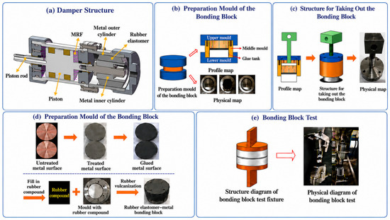
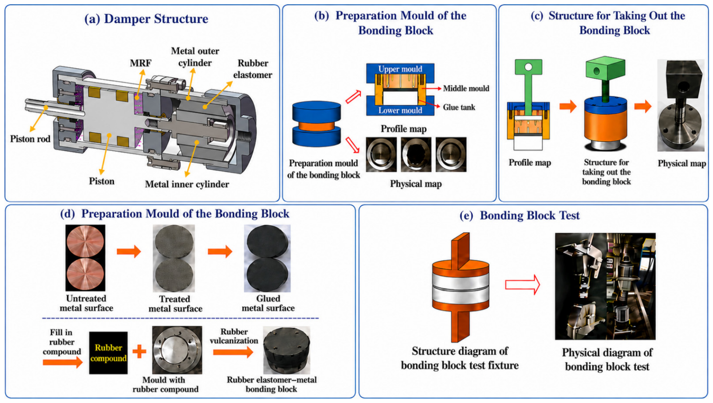
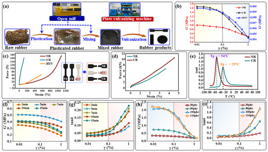
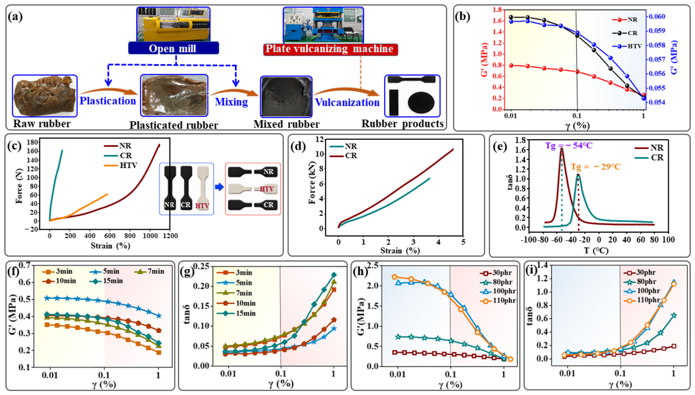
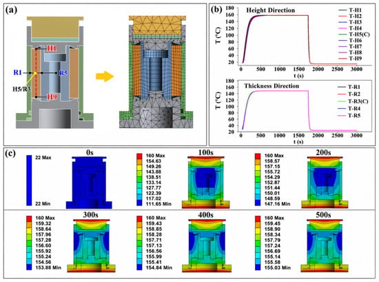
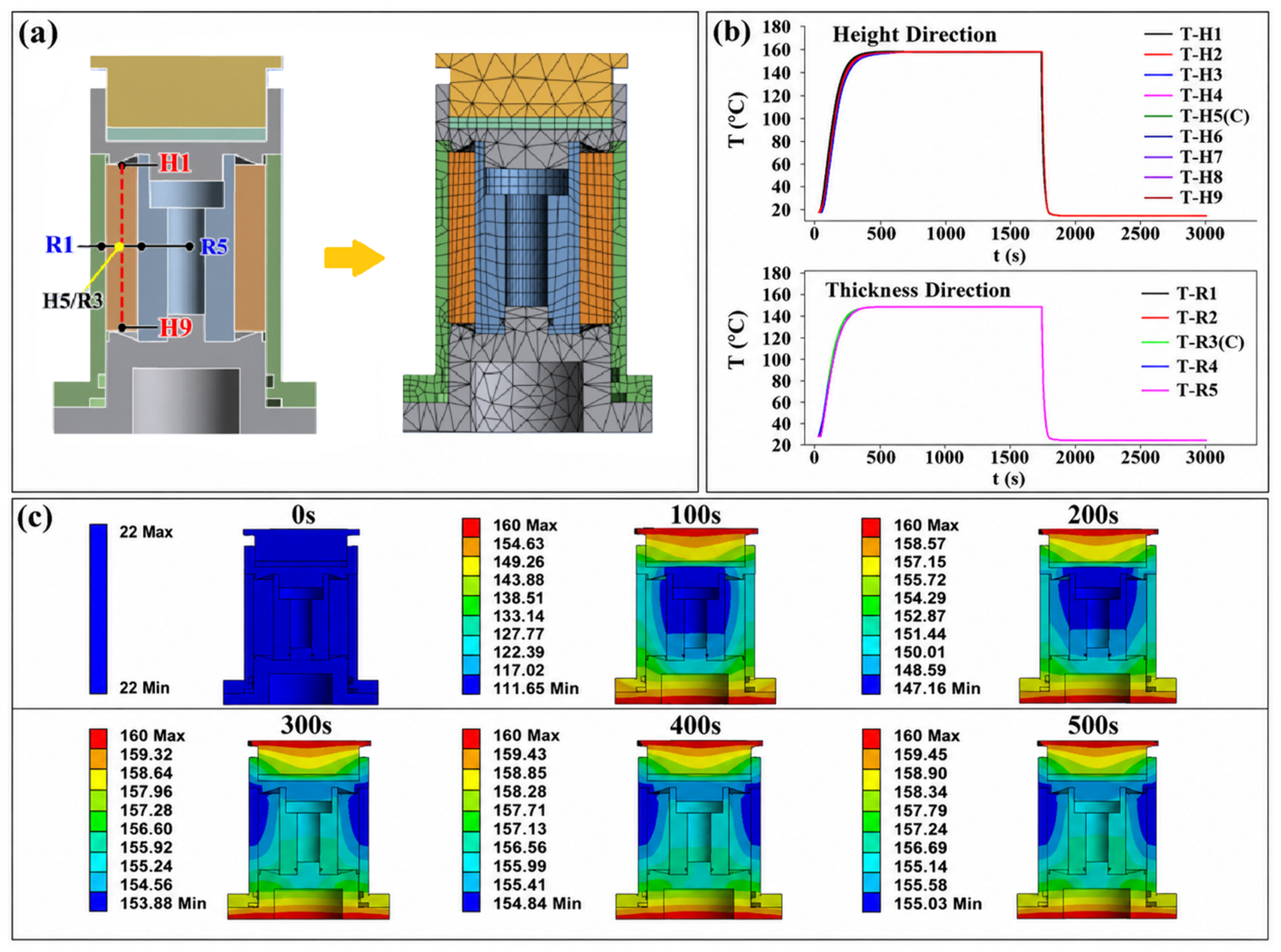
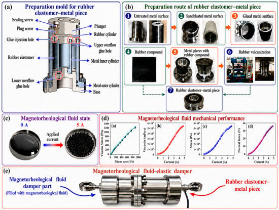
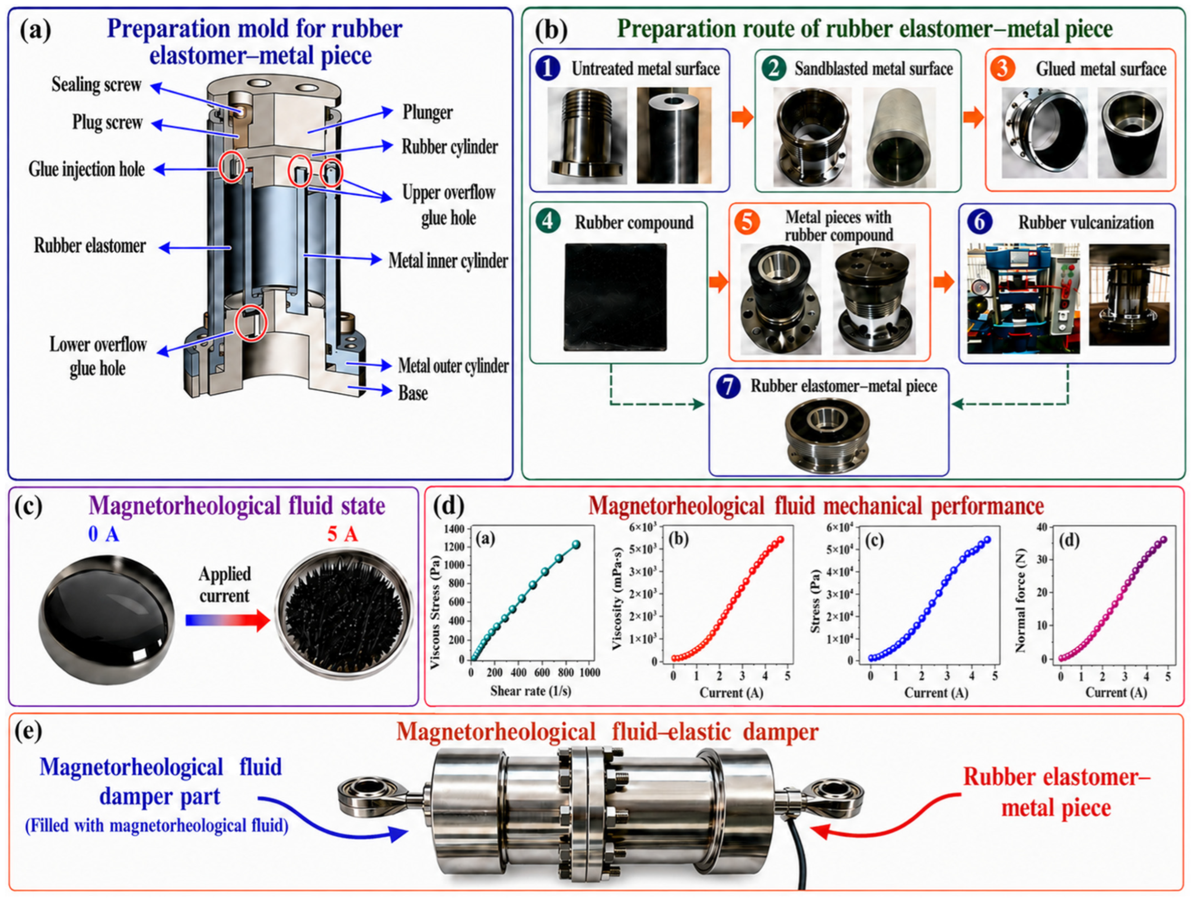
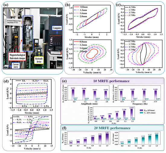
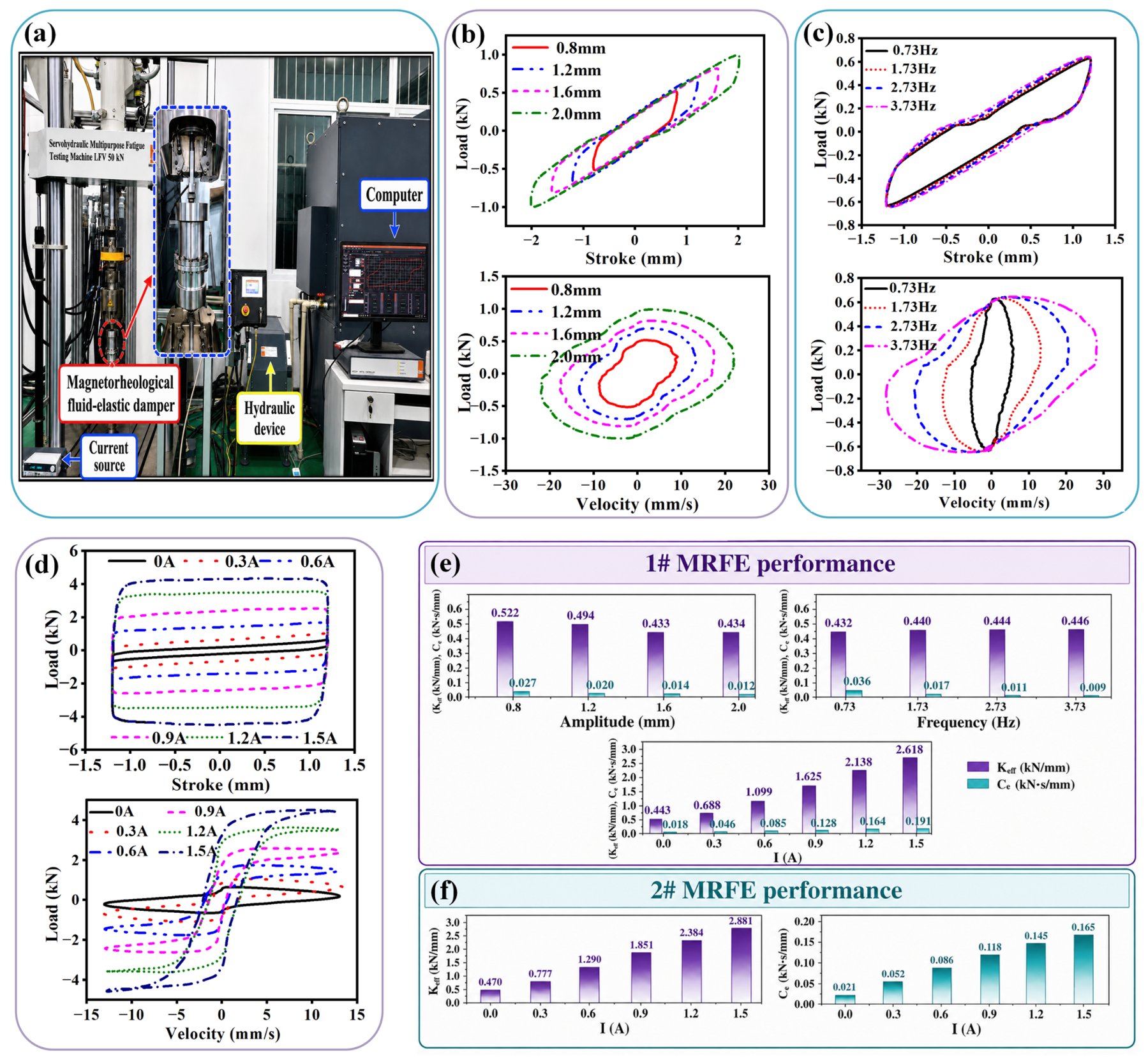
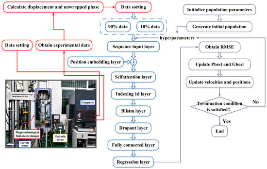
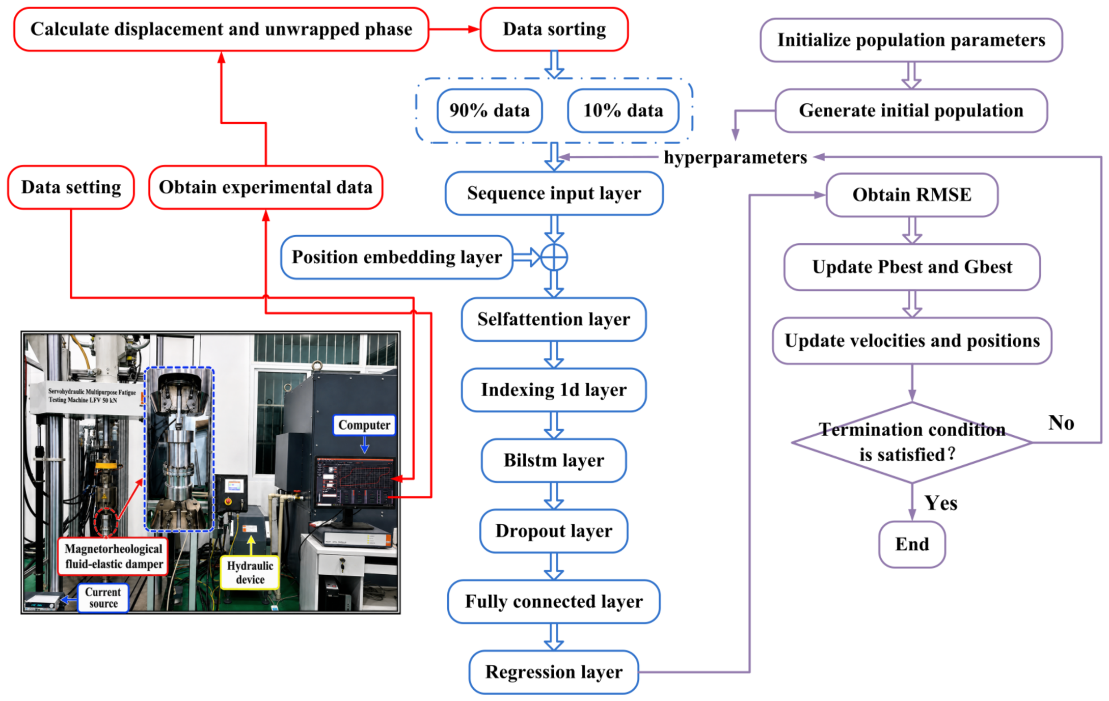
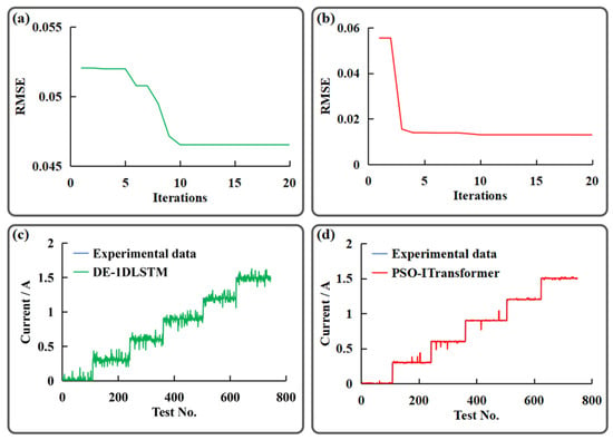
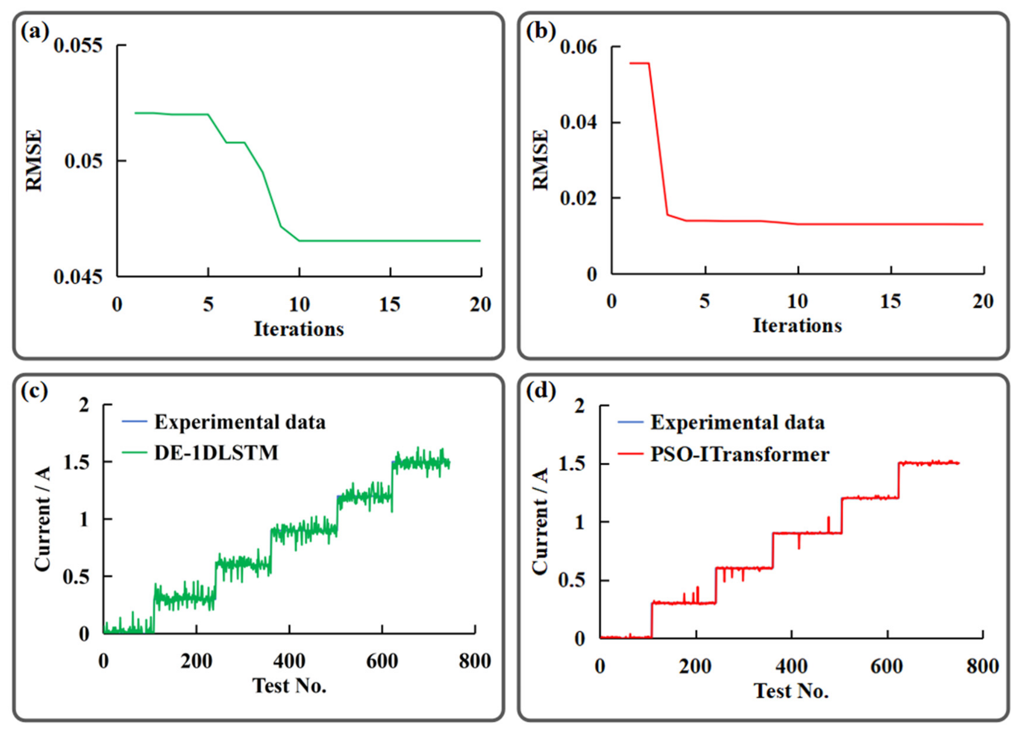

Disclaimer/Publisher’s Note: The statements, opinions and data contained in all publications are solely those of the individual author(s) and contributor(s) and not of MDPI and/or the editor(s). MDPI and/or the editor(s) disclaim responsibility for any injury to people or property resulting from any ideas, methods, instructions or products referred to in the content. |
© 2026 by the authors. Licensee MDPI, Basel, Switzerland. This article is an open access article distributed under the terms and conditions of the Creative Commons Attribution (CC BY) license.