


Abstract
Digital twin (DT) technology has become a transformative engineering paradigm for metal-cutting machine tool systems and materials-processing equipment, enabling real-time synchronisation, predictive analytics, and intelligent decision-making throughout the entire production cycle. This systematic review summarises the latest advances in the engineering-oriented implementation of digital twins, with a focus on their modelling frameworks, tool condition monitoring, compensation for geometric, kinematic, thermal and dynamic errors, fault diagnosis and adaptive control, and on the application of this technology to lathes, milling machines and grinding machines. The search for and selection of literature were carried out in accordance with the PRISMA 2020 guidelines. In total, 680 records were identified in Google Scholar in May 2026, of which 197 studies met the inclusion criteria and were synthesised narratively within six thematic sections. The analysis demonstrates that modern digital twin architectures integrate multiphysics modelling, multi-sensor data fusion, and machine learning to create high-precision virtual replicas of physical assets. Predictive maintenance and fault diagnosis systems use machine learning and deep learning to detect incipient faults in feed systems, spindles, and other critical components before failure. The review also analyses existing challenges and outlines future research directions for reliable industrial digital twins.
1. Introduction
Until the end of the 18th century, industry relied mainly on manual labour supplemented by mechanical devices. The Industrial Revolution, which began in the second half of the 18th century in Great Britain, facilitated the transition from manual labour to machine-based production. However, this fundamental shift occurred in several stages, as illustrated in Figure 1. The history of industry dates back to the 18th century, beginning with the mechanisation phase around 1780, which was characterised by the introduction of water and steam power into manufacturing. Later, in the 1870s, the era of electrification in industry began with the introduction of electricity and mass production methods. The third stage is automation, which emerged in the 1970s. This stage enables industry to adopt programmable logic controllers (PLCs) and information technology (IT) systems to automate production processes [1].
Figure 1.
Industrial revolution from Industry 1.0 to Industry 4.0 [1].
Thus, the foundations have been laid for the fourth industrial revolution, commonly referred to as Industry 4.0 or the Connected Era, which focuses on the use of the Internet of Things (IoT), artificial intelligence (AI), and digital technologies for intelligent automation and advanced data exchange in manufacturing. In this revolution, digital twins have become key elements in the evaluation and optimisation of production processes and systems. Historically, each industrial revolution has given new impetus to industrial growth, and in the era of Industry 4.0, digital twins are becoming one of the main technologies driving this growth.
Digital twins are particularly important in the context of Industry 4.0, as they act as a bridge between the physical and digital worlds. A digital twin is, in essence, a high-quality digital replica of a physical object. This physical object can be a product, process, or system that enables real-time monitoring, modelling, and analysis. The virtual model reflects the physical object in every respect, including its operational states, performance metrics and environmental conditions. Through continuous data collection and feedback loops, digital twins enable predictive maintenance, improved operational efficiency, and process optimisation in ways that were previously unattainable with traditional methods [2].
Originally developed for military and aerospace applications [3], digital twins are currently being actively applied across a wide range of sectors: in industry, in medicine (for the treatment of diseases, healthcare management and sports planning), in the energy sector, in smart cities, in aerospace engineering, and in the business world (offline sales and online sales) [4].
Digital twins are also widely used to represent individual pieces of equipment in a virtual environment and to model large-scale systems, such as workshops, factories, cities, and the logistics of entire regions and countries.
Consequently, much of the research and development on digital twins for industrial applications focuses on solving specific tasks, such as monitoring and controlling technological processes, improving product quality, analysing the condition of equipment and its components, and identifying maintenance requirements. By increasing equipment efficiency and reducing unplanned downtime, these applications directly contribute to sustainable industrial growth.
In many modern applications, however, the goal of a digital twin is not to create a virtual copy of an object but to monitor and control technological processes and equipment. For this purpose, sensors determine the necessary process and/or equipment parameters. The digital twin analyses these parameters and controls the actuators via controllers. The sensors, in turn, monitor the performance of the actuators. In this way, a closed-loop control system is created, in which the digital twin plays a key role.
Machine tools are the primary production assets of modern manufacturing, often referred to as the ‘mother machines’ of industry, as they determine the geometric accuracy, surface quality and productivity of the machined parts [5].
Geometric and thermal errors are important for high-precision machining. This is because machine tools generate volumetric errors due to thermal deformation, spindle runout and structural distortions. This results in reduced precision and consistency of the finished parts.
In addition to dimensional accuracy, a machine’s reliability depends on the early detection of faults and degradation. Tool condition monitoring and wear prediction have become central to digital twins for Computer Numerical Control (CNC) machine tools. Engineering-focused digital twins also support commissioning and the communications infrastructure. Virtual commissioning of machine tools enables testing of control logic, motion programmes, and process parameters using a virtual replica prior to physical start-up, thereby reducing risks and shortening lead times [6].
In this context, the article aims to provide a systematic analysis of the application of digital twins to monitor and compensate for actuator errors in metal-cutting machine tools, such as the spindle, workpiece feed mechanism, cutting tool, and grinding wheel.
This review examines the application of digital twins specifically designed for machine tool systems and materials-processing equipment, drawing on the expanding literature on digital twin modelling, machine intelligence, and data-driven predictive maintenance. It synthesises the latest advances in architectural modelling, monitoring of wear, vibrations and tool condition, thermal error control, fault diagnosis, predictive maintenance, virtual commissioning and communication infrastructure. The studies reviewed cover CNC machine tools, milling and grinding operations, robotic machining equipment and production lines in stone factories, reflecting the breadth of the industry whilst maintaining a focus on engineering implementation.
Particular attention is paid to research that combines machine learning with physical models and integrates real-time sensors with virtual replicas. Focusing on machine tools and associated equipment for materials processing, this review aims to provide a comprehensive, systematic overview of how digital twins are used to improve accuracy, reliability, productivity and adaptability in manufacturing operations.
In this context, the article first examines the industrial revolutions. Then, it outlines the role and applications of digital twin technology. Particular attention is paid to the use of digital twins to compensate for geometric and thermal errors in metal-cutting machine tools, to monitor tool condition, and to predict wear and vibrations.
Metal-cutting machine tools constitute the technological foundation of mechanical engineering and the automotive and energy industries, through which raw stock is transformed into precision components. The full spectrum of tasks and functions performed by digital twins of metal-cutting machine tools has been systematised and structured, ranging from the selection of equipment for constructing a machine-tool twin to the analysis of successfully implemented solutions for correcting various classes of machine-tool errors. On this basis, an algorithmic chain of tasks has been constructed that can serve as the foundation for developing a digital twin that accounts for all essential factors influencing machining accuracy. Accordingly, one of the prospective directions for further research and development on digital twins has been identified, namely, the formulation of a universal algorithm of tasks for the construction of digital twins of machine tools.
The structure of the article is as follows: Section 2 presents the methodology for searching and analysing the literature. Section 3 consists of six subsections. Section 3.1 describes the concept of digital twins, and Section 3.2 covers equipment for the digital twins of metal-cutting machine tools. Section 3.3 analyses physics-based and data-driven DT models. Section 3.4 covers machine tool errors that DTs monitor and correct. Section 3.5 describes DTs for analysing machine anomalies and predicting machine failure, and Section 3.6 covers the application of DTs to metal-cutting machine tools. Section 4 discusses the potential of using digital twin technology for machine tools, highlights the need to move from narrow-task to multi-task digital twins and to integrate them with machine learning and artificial intelligence, analyses the challenges of implementing digital twins, and identifies directions for future research in this area.
2. Methodology
This systematic review was conducted in accordance with the PRISMA 2020 guidelines [7]. PRISMA 2020 was used to ensure transparency and reproducibility in the identification, screening and selection of relevant literature on digital twins. Consequently, the literature reviewed covers sensors and measuring instruments, modelling approaches, diagnostics and forecasting, real-time control and integration, and software architectures.
The literature search was conducted using Google Scholar as the primary academic database, as it offers a broad interdisciplinary coverage of literature on engineering and manufacturing. In particular, it indexes IEEE and ASME conference proceedings, journal articles and open-access publications, aggregating records from all major publishers in the field, including Elsevier, Springer Nature, IEEE and MDPI. The use of this database as the single principal source was therefore considered sufficient for the topic of this review, and its known limitations were additionally compensated by citation searching, as described below. The database search was carried out in May 2026 with the publication-year filter set to 2023–2026. Only English-language peer-reviewed journal articles and conference papers were considered eligible.
To mitigate the limitations of using a single database, both backwards and forward snowballing were applied. The citation searching was completed in June 2026. The reference lists of the most frequently cited retrieved papers were manually screened. In addition, the “Cited by” feature of Google Scholar was used to identify subsequent relevant works. All retrieved records were imported into the Zotero reference management software (version 7, Corporation for Digital Scholarship) for deduplication, screening, and thematic classification.
The search queries were organised into seven functional categories. These categories reflect the functional components of a machine-tool digital twin: general scope, conceptual framework, sensing and instrumentation, modelling, diagnosis and PHM, control and integration, and software architecture. This category-based strategy was adopted for a clear reason. The components serve distinct functional roles, ranging from data acquisition and modelling to diagnostics, control, and system integration. Consequently, they require different search keywords.
Thus, each query was created as a combination of the core term “digital twin” with a target-system term such as machine tool, CNC, actuator, servo drive, spindle, feed drive, machining, or manufacturing. In total, thirty-four distinct search queries were constructed. For each query, the first 20 records in the Google Scholar relevance ranking were retrieved for initial screening. The full list is presented in Table 1.
Table 1.
Search strings used in the review, grouped by functional category.
The selection process followed a two-stage PRISMA-compliant workflow conducted by the first author, with uncertain cases resolved by discussion with the co-authors. The complete PRISMA flow of the selection process is shown in Figure 2. The first stage involved screening the studies by title and abstract. During this stage, 34 search queries were conducted, resulting in 680 sources being retrieved (34 queries with up to 20 records each). After removing duplicate sources, the number of publications was reduced to 520. Then, the number of sources was reduced to 455 by excluding studies that were clearly outside the scope of manufacturing or machine tools. During the second stage, 190 publications were selected based on the four criteria listed below. Together with seven additional studies identified through backwards and forward snowballing, this yielded the final corpus of 197 included studies. The complete list of the 197 included studies is provided in Table S1 of the Supplementary Materials. These 197 publications include 180 primary sources (157 research articles, 22 conference papers, and 1 dissertation) and 17 review articles. The review articles were used only as background sources for the conceptual sections and as starting points for citation searching and were not treated as primary evidence in the technical synthesis.
Figure 2.
The complete PRISMA flow.
The reviewed corpus includes both primary studies and review articles, since conceptual issues such as definitions and taxonomies are mostly synthesised in review papers rather than in experimental works. The four criteria listed below were applied to primary studies during full-text assessment. Review articles do not present original validation by their nature; therefore, the validation criterion was not applicable to them. Such articles were retained as background sources for the conceptual sections of this review and as starting points for citation searching. The first criterion was that the definition and scope of the digital twin had to be clearly stated. Second, the methodological description had to be adequate, including the modelling approach, the sensor configuration, and the validation method. Third, the study had to include experimental or simulation-based validation. Fourth, the study had to be relevant to actuator-level systems in manufacturing. In parallel, citation searching (snowballing) identified 7 additional relevant studies, all of which met the eligibility criteria described above and were retained. Thus, 197 sources were identified, 190 through database searches and 7 through a cited sources search. This also explains the presence of 2022 publications in the corpus, despite the search filter being set to 2023–2026.
Since formal risk-of-bias tools developed for clinical research are not applicable to engineering literature, a descriptive quality assessment was performed instead. Each candidate primary study was assessed against the four criteria listed above. Each criterion was assessed in a binary manner, that is, met or not met, and only studies that met all four criteria were included. Studies that scored low on these criteria, for example, purely conceptual papers without a technical methodology or validation, were excluded during the full-text screening stage. The results of this assessment informed the interpretation of the evidence, in particular, the discussion of the reproducibility of validation protocols and the need for open benchmarks presented in Section 4.
The complete PRISMA flow of the selection process is shown in Figure 2.
A standardised data extraction form was used to record the following variables for each included study. The form covered bibliographic information (authors, year, title, and source) and document type (research article, review article, conference paper, and dissertation). It also covered the methodological approach (physics-based, data-driven, or hybrid modelling) and experimental or simulation-based validation. In addition, the form recorded the technical focus (sensing and instrumentation, modelling, diagnosis and PHM, control and integration, or software architecture) and the target actuator system (servo feed drive, spindle system, multi-axis CNC, robotic manipulator, or general machine tool). Finally, the key findings and contributions were recorded. Data extraction was performed by the first author and verified by the co-authors.
The 197 included studies were published between 2022 and June 2026 (Figure 3): 7 studies in 2022, 39 in 2023, 61 in 2024, 59 in 2025, and 31 in the first half of 2026. This distribution is partly shaped by the design of the search: the year filter favoured publications from 2023 onward, studies from 2022 entered the corpus only through snowballing, and the year 2026 is covered only partially. Figure 3, therefore, characterises the composition of the reviewed corpus rather than the publication dynamics of the field as a whole.
Figure 3.
Distribution of the included studies by year of publication.
The five most frequent sources account for 72 studies, or 36.5% of the corpus. These are the International Journal of Advanced Manufacturing Technology (24 studies), the Journal of Intelligent Manufacturing (17), the Journal of Manufacturing Systems (13), Robotics and Computer-Integrated Manufacturing (9), and Machines (9). The next most frequent sources are Mechanical Systems and Signal Processing (5), IEEE Access (5), Digital Twin (5), Scientific Reports (4), and Procedia CIRP (4). Together, the ten most frequent sources cover 95 studies, or 48.2%. At the publisher level (Figure 4), Springer Nature (58 studies, 29.4%) and Elsevier (52 studies, 26.4%) together account for more than half of the corpus. They are followed by MDPI (25, 12.7%), IEEE (12, 6.1%), Taylor & Francis (9, 4.6%), and SAGE (3, 1.5%). The remaining 38 studies (19.3%) originate from smaller or society publishers.
Figure 4.
Distribution of the included studies by publisher.
3. Results
3.1. Digital Twin Concepts
3.1.1. Definition of Digital Twin
General issues of the digital twin concept have been considered at a sufficient level in many studies and review articles and are not the central topic of this review, but are necessary for understanding the content of the presented studies. Therefore, it is advisable to take a short excursion into the interpretation of the definition of a DT, its taxonomy and the architecture of the DT used for machine tools.
A digital twin is a virtual representation of a physical asset, process, or system that mirrors its behaviour and remains synchronised with it through continuous data exchange [8,9].
The concept of a digital twin originated in product lifecycle management, where the initial 2003 formulation divided the DT into three parts: the physical product, the corresponding virtual product, and the data linking them. In 2012, the concept was significantly refined, with the DT understood as an ultra-high-precision, multi-physics, multi-scale, probabilistic simulation that reflects the state of its physical counterpart by integrating historical data, real-time sensor streams, and physics-based models.
A production-oriented interpretation is provided by a definition that characterises the DT as “the real-time digital coupling of the state of a physical asset or process with a virtual representation and functional output” and breaks it down into six highlighted parts [10]: live, digital coupling, state, physical product or process, virtual product, and functional output. The data connections between these elements are illustrated schematically in Figure 5.
Figure 5.
Schematic of the data connections of digital twins.
Consequently, a DT is formally defined as a digital representation of an observed element, with synchronisation between the element and its digital representation [6], whilst consolidated terminology regards a DT as a type of digital asset rather than merely a digital representation [9].
Standardisation and interoperability remain central engineering challenges. Standardisation has consolidated the terminology. In the ISO 23247 [11] series, a manufacturing digital twin is defined as a digital representation of an observable manufacturing element, corresponding to its intended purpose, with synchronisation between that element and its representation. Shao [8] links the popularity of digital twins to standardisation. He emphasises that DTs form the basis of digital transformation and smart manufacturing, while the IoT, the cloud, and intelligent sensors are key factors.
In the context of machine tools and metalworking equipment, this physical–virtual link is the key mechanism underpinning the intelligent capabilities of machine tools, ranging from geometric and kinematic modelling to the optimisation of manufacturing processes and lifecycle management. Qin and Pan [12] describe DT as a technology that accurately replicates physical objects and establishes a seamless connection between them and their virtual counterparts, thereby supporting understanding, optimisation, and prediction. Nele and Mattera [13] add that digital twins combine real-time data and simulation to improve the performance of physical assets, with machine learning being used to optimise applications at various scales. They propose to describe the structure in terms of three levels: perception, digital objects, and applications. This three-level structure is illustrated in Figure 6.
Figure 6.
The layered framework of a digital twin.
The layered framework of a digital twin facilitates data collection, prediction, and advanced analytics for applications such as visualisation, anomaly detection, classification, feedback control, and optimisation [13].
These conceptual foundations are further reinforced by Duane and Gao [9], who analysed the definitions and concepts of DTs, as well as by Li and Go [14], who developed a DT for a three-dimensional (3D) gear-based measurement system, illustrating how a DT acts as a ‘bridge’ between information and physical spaces.
3.1.2. Taxonomy of DTs
Whilst the conceptual literature centres on merging physical and virtual data, there is less consensus on how to classify digital twins. Taxonomic studies are crucial for engineering-oriented development, as they distinguish descriptive DT research from prescriptive frameworks that guide system design, data integration and model selection. Thus, Aurich and Mertes [15] proposed one of the most comprehensive manufacturing-oriented taxonomies, classifying DTs across level of data integration (digital models, digital shadows, and DTs), application purpose (analysis, monitoring and control, and prediction), and manufacturing system hierarchy (factory, machine, and process), and utilised model type (white-box, black-box, and grey-box). Ozkaya and Turunc [16] supplement this by presenting a classification framework specifically designed for digital twin tools, which helps to compare the capabilities of different DT platforms and simulation environments. In another study, Li and Yang [17] apply a multifaceted energy-efficiency forecasting system to processing systems, demonstrating how classification by process type and function can support sustainable development objectives.
Within this taxonomy, DT objectives are divided into three functional classes: analysis, monitoring and control, and forecasting. In machining, these functions are implemented in several ways. Examples include multifaceted prediction of energy efficiency with intelligent alerts based on machine, workpiece, tool and process factors [17]. Further examples are deformation forecasting and control for thin-walled components [18], forecasting the remaining service life of spindle bearings, motors and cooling systems [19], analysis of measurement errors in gear metrology [14], and augmented reality (AR)-supported monitoring of gearbox condition [20].
A digital model represents a physical object in virtual space, but cannot be automatically updated based on sensor readings. In contrast, the digital shadow is automatically updated via a one-way data flow from the physical space. The digital twin achieves the highest level of integration, in which an automated two-way data flow also enables the virtual model to control the physical system. The distinction between the digital model, the digital shadow and the digital twin is illustrated in Figure 7. This real-time bidirectional interaction distinguishes a DT from an offline simulation, as the twin operates online. Consequently, it continuously integrates up-to-date data received in real time from actual equipment and technological processes.
Figure 7.
Distinction between digital model, digital shadow and digital twin based on integration level [15].
3.1.3. DT Architecture
The taxonomic literature is accompanied in parallel by a growing body of work on reference architectures for machine tools and CNC systems. These architectures typically organise DTs into sensor, communication, data, model and application layers. They also define how data from physical equipment is mapped to virtual models. Yu and Yu [21] developed a DT architecture for CNC systems based on edge intelligence. Their architecture and deployment strategy bring real-time inference closer to the machine controller. Deployment platforms span edge and cloud infrastructures. Edge-intelligence approaches partition and select models for real-time response. Kia et al. [22] presented real-time DT simulation platforms that leverage graphics processing units (GPUs), field-programmable gate arrays (FPGAs), and personal computer (PC) clusters for virtual testing and ageing assessment of electrical machines. Open challenges include data availability, compatibility, scalability, and portability of PHM solutions [23].
The canonical DT architecture consists of three interacting elements [12]: the real space, the virtual space, and the communication flows between them.
The real space contains physical objects such as machines, equipment, spindles, power axes, and plants that exist and operate in the real world, continuously generating data in real time [5]. The virtual space is its digital replica, in which the characteristics and behaviour of the physical object are reproduced using computer modelling [12]. Communication flows act as a bridge: they collect and transmit data in real time from the real space to the virtual space for analysis and modelling, and feed the results of virtual-space optimisation back into the real space to control real-world operations and decision-making. In industrial applications, this bridge is most commonly implemented via OPC UA, which is effectively the standard communication protocol for manufacturing processes [24].
Beyond the canonical three levels of DT architecture, the structure varies by application area. A DT on a machine tool consists of four dynamically interacting components [5]. These are the machine tool object (mechanical structure, CNC and servo drive systems, external sensors, and time-varying coupling coefficients such as cutting force), the DT model, the decision-making and control system, and data. The architecture of this system is illustrated in Figure 8. Together, they form a closed-loop perception-modelling-prediction-control system.
Figure 8.
Four-component architecture of the digital twin of the machine [5].
Subject-specific implementations either extend the stack or break the virtual model itself down into functional layers. The stack can have up to eight layers, for example, for a stone-processing production line [24]. A multi-level architecture of this kind is illustrated in Figure 9. Functional layers include dimension, connection, motion and error layers, as well as user-defined layers built on the Unity3D platform for a gear measurement system [14].
Figure 9.
The multi-level architecture for supporting the digital twin [22]. The circled numbers 1–8 indicate the eight layers of the architecture, from the physical twin (1–3) through the middleware and databases (4–6) to the user interfaces (7) and data processing (8).
Thus, the group of studies discussed centres on several open challenges. These include consensus on definitions, interoperability, real-time virtual–physical synchronisation, and hybrid modelling. Together, they define the research directions for digital twins in machining.
3.2. Equipment for Machine Tool Digital Twins
The equipment used to implement digital control on machines will be considered in accordance with such classes as sensors, communications equipment, controllers, drives, output devices, and computing infrastructure.
The physical layer of the machine tool digital twin is best introduced through its sensors. Cao [25] divides them into six widely used categories, each measuring a distinct physical quantity. Dynamometers measure cutting forces along three axes and torque. Strain-gauge designs cover the low-kilohertz range, while piezoelectric designs reach approximately 10 kHz. A stationary dynamometer is mounted between the workpiece and the table. A rotating one, in contrast, is mounted on the spindle [25]. However, their high cost, size constraints, and impact on machine rigidity limit their practicality in industry [26].
Accelerometers are used when force cannot be measured directly. They are available in piezoelectric and Micro-Electro-Mechanical Systems (MEMS) versions and provide high-frequency vibration signals. In addition, they are valued for their cost-effectiveness, ease of retrofitting, and installation without shutting down the equipment [25,27]. Because the cutting zone is difficult to access, they are typically mounted on the spindle housing or near the tool.
A further category is the acoustic emission sensor. It detects elastic waves generated by deformation and fracture. Continuous signals indicate plastic deformation and wear on the side surfaces, whereas pulsed signals indicate crack initiation, fracture, and chip formation [25].
Displacement sensors come in three types: Linear Variable Differential Transformer (LVDT), eddy-current, and laser. They monitor geometric errors, surface quality, and thermal deformation. Machine vision systems complete the picture. They measure flank wear and surface roughness directly and online, but require interrupting the process and controlling the illumination [28]. Comparative assessments show that force and vibration measurements are the most sensitive to changes in the cutting edge’s condition. In contrast to force and vibration signals, acoustic and spindle/feed current signals are often distorted by production noise.
Selecting the right monitoring configuration is therefore important, as it can save up to 40 percent on tooling costs [26]. Beyond these categories, spindle vibration is measured with piezoelectric tool-mounted sensors or with smart sensors that output acceleration, velocity, or displacement [29]. Natarajan et al. [30] captured machining sound with an ordinary USB microphone.
A second distinction, beyond the choice of the measured quantity, separates internal from external sensing. The machine manufacturer installs internal sensors, which do not affect the manufacturing process. However, they may be insufficiently sensitive to changes in tool condition [31]. External sensors are therefore mounted close to the tool and the workpiece [32]. Typical examples are dynamometers, accelerometers, acoustic emission sensors, thermocouples, and cameras. An integrated alternative is the smart tool developed by Zhang et al. [33].
It is a tool holder with embedded force, acceleration, and temperature sensors, as well as on-board electronics. Its analogue signals are digitised in an analogue-to-digital converter (ADC) pipeline of sampling, quantisation, holding, and encoding. The data are then buffered in a ping-pong scheme and streamed via a Serial Peripheral Interface (SPI) and Wi-Fi over Transmission Control Protocol/Internet Protocol (TCP/IP) to a host computer. On the host computer, the LabVIEW application reconstructs and displays in real time the cutting force, vibration, and temperature.
Tonejca et al. [34] followed a similar idea. They coupled a sensorised tool holder with containerised Python applications on a modern edge device. Standard protocols provided comparable capabilities and independence from the host operating system.
A complementary line of work addresses big-data environments, in which virtual sensors replace failed physical channels. Manuja et al. [35] demonstrated virtual sensor recovery on an aero-engine test bed with roughly 600 sensors for temperature, pressure, vibration, strain, and lubrication. Their virtual sensors combine historical and current measurements to mimic the physical sensors during multiple simultaneous failures.
On the modelling side, a formal connection model [36] classifies virtual sensors into geometric, physical, behavioural, and rule categories. It also defines an ontological sensor model covering configuration, interface, collection object, and accuracy. Finally, it organises physical sensors, virtual sensors, and aggregation nodes to convert operational technology data into information technology data.
Once the signals are captured, they are acquired and transmitted through a layered protocol landscape, using communications equipment. It is classified here as the second class of equipment. Here, OPC UA functions as the de facto standard for production data exchange [36,37]. OPC UA uses a client-server architecture. The server receives, manages, and exposes production data as nodes in its address space. Client applications, in turn, issue read and write requests to feed upper-level applications [36,38]. In five-dimensional architectures, OPC UA channels link CNC systems with DT applications [39].
Protocol interoperability has been examined from two directions. Barnard [40] compared the Asset Administration Shell (AAS), OPC UA, and AutomationML in terms of architecture, data modelling, scalability, and security. Braunisch et al. [41], in turn, presented a model-driven mapping that generates OPC UA node sets from the formalised AAS metamodel for lossless exchange. Among the practical limitations of OPC UA are the complexity of data retrieval and restrictions on the frequency of Application Programming Interface (API) calls in large-scale systems. These limitations have therefore spurred the development of open-source servers and web-based digital terminals [42].
Complementary protocols address different segments. For example, Cabral et al. [43] transmitted data from machine tools to cloud platforms via MTConnect, using Message Queue Telemetry Transport (MQTT) in publish mode. This eliminates the need for client-side polling, and MQTT ensures real-time transmission with low latency. Alongside it, NC-Link reveals the internal state of CNC systems [44]. In addition, EtherCAT, combined with the Automation Device Specification (ADS) data distribution protocol, links the CNC and the DT to provide adaptive force control [45].
The choice of protocol often depends on the pair of devices between which communication is to take place. For example, the Modbus protocol is used for communication between sensors and computers, Profinet for communication between computers and controllers, and OPC UA for communication between controllers and actuators [46]. In the case of more complex systems, such as robotic cells, a combination of fieldbus options such as Profibus and Modbus, Ethernet variants such as Profinet, EtherCAT and Modbus TCP, and wireless communication channels, can be utilised [47]. Socket-based TCP/IP communication supports synchronous mapping between robots and their twins [48], while HTTPS with WebSocket serves spindle-twin communication [49]. Mazen et al. [50], for instance, used Azure IoT Hub to stream position data and simulated signals from an old lathe. Open CNC ecosystems such as LinuxCNC provide a pipeline that covers acquisition, processing, and distribution, together with a Unity-based virtual representation, at a mean response time of 50.46 ms [51]. Finally, Mertes et al. [52] validated private standalone 5G networks with edge computing as a suitable industrial communication for machine tool DTs. However, instability, expertise requirements, and high costs currently hinder their use in closed-loop, real-time systems.
Controllers and CNC systems form the third equipment class. Programmable logic controllers coordinate gantry milling workstations and lathe twins through TCP/IP and OPC connections [53,54]. In the grinding twin developed by Li et al. [55], a Programmable Multi-Axis Controller (PMAC) receives Numerical Control (NC) codes from an industrial PC and drives servo axes with high-precision grating-scale feedback. At the same time, the machine Programmable Logic Controller/Programmable Machine Controller (PLC/PMC) supplies electrical, mechanical, load, and state signals together with counters and timers. Qiu et al. [56] took a different route. They combined the CNC with a high-performance motion controller to enable servo-drive self-excitation. The drives inject identification signals for modal parameters during normal operation, which reduces the need for external instrumentation.
Open controllers also play a role. Pantelidakis and Mykoniatis [51] validated a small and medium-sized enterprise (SME)-oriented twin built on LinuxCNC over more than 230 machining cycles. Petru et al. [57] closed the X, Y, and Z loops of a small CNC centre using open-source microcontroller boards and stepper drivers, driving direct current (DC) servomotors with encoders. The Proportional-Integral-Derivative (PID) parameters were pre-tuned in a co-simulation combining Simulink and Simscape. Thermal compensation systems, in turn, couple directly with machine operating systems, such as the machine’s CNC, over Ethernet [58].
Closing the loop, actuators and drive systems constitute the fourth class. They serve both as objects of twinning and as the means by which twin decisions act on the process. Chiou et al. [59] represented servo feed drives using discrete dual mass-spring-damper models. The position- and velocity-loop parameters were identified from frequency-sweep tests using particle swarm optimisation. Xie et al. [60] built a servo experimental platform combining NX Mechatronics Concept Designer, PLCSIM Advanced, and the TIA Portal. The platform achieves seamless synchronisation with the real production system for servo parameter design. Hsieh and Smith [61] presented an augmented-reality-assisted self-adjusting twin of a servomechanism. It updates its own internal model parameters and reproduces angular velocity under load torque with high accuracy.
The fifth class includes machine drives. At the process level, the twin acts through the machine’s actuators. Excessive tool wear triggers a tool-change command issued to the CNC through G-code feedback, and the machine replaces the tool from its magazine [62]. Detected tooth breakage, in turn, triggers an immediate feed stop [63].
Actuation-level implementations, however, extend well beyond tool management and protective interlocks to continuous process control on this and other equipment. In milling, closed-loop twins adjust the feed rate in real time to hold the cutting force at a reference level [45] or to maximise it within contour-error limits [64], and in Carbon Fiber Reinforced Polymer (CFRP) drilling the twin continuously updates the critical feed rate to suppress exit delamination [65]. Grinding twins issue compensation instructions directly to the machine [66] and correct process parameters autonomously in real time [67], whereas outside metal-cutting machine tools, such as a rolling-mill-stand twin, couples drive-system behaviour with the vibration response of the rolls for virtual commissioning and process-parameter optimisation [68].
On the experimental side, Chaiprabha and Chancharoen [69] developed a linear-stage rig that executes a Simscape model on an embedded single-board computer in parallel with the physical stage. The rig supports open-loop experiments with programmable voltage and closed-loop experiments with programmable stiffness, both under a stiff Proportional-Derivative (PD) controller.
Augmented reality interfaces also serve as shop-floor output devices. For example, Pitzalis et al. [20] overlaid twin outputs directly on the physical equipment. The displayed information included gearbox condition, internal component views, operating-parameter plots, and maintenance instructions. They implemented the interface with Vuforia Studio and ThingWorx on affordable hardware.
The computing infrastructure closes the equipment stack. Edge-intelligence approaches partition and select models so that CNC DT functions meet real-time constraints on resource-limited edge devices [21]. Building on this idea, Wang et al. [70] demonstrated the interaction between the cloud and the periphery. This was done to ensure a balance between response time, computational load and data privacy for tool condition prediction and performance management services. In similar deployments, intelligent functions are located at different levels of the hierarchy. Edge servers host thermal-error compensation models close to the machine [71], fog layers run error prediction, and the cloud retrains improved models such as the Improved Bat Algorithm—Gated Recurrent Unit (IBA-GRU) [72]. In another study, Chehrehzad et al. [73] run digital shadows on industrial edge devices that infer drill flank wear directly from machine-side signals. More experimental arrangements combine bidirectional DTs with mobile edge computing in metaverse environments. There, local and global twin engines must cope with twin desynchronisation, migration, and catastrophic forgetting, which they address through continual learning [74]. Finally, Wu et al. [75] organise distributed deployments with an edge server at the physical level and a cloud server at the digital level. Data are collected through OPC UA or vendor DLLs and subjected to validation, filtering, and mean imputation.
3.3. Physics-Based and Data-Driven Models of Digital Twins
Digital twin models are categorised into three main types: physics-based (white-box), data-driven (black-box) and hybrid (grey-box) [15]. Physics-based models are built from first principles and explicit mathematical relations. Thus, they offer interpretability and physical consistency. However, they have high computational cost, weak real-time adaptability, and dependence on simplifying assumptions. Data-driven models, in contrast, learn input–output mappings from measured data. Hybrid models combine the two.
A widely adopted physics-based model system is the four-model virtual product proposed by Zhang et al. [76]. It comprises geometric, physical, behavioural, and rule models. These models are validated through Verification, Validation and Accreditation (VV&A). The geometric model describes shape and size through parameters such as length, diameter, radius, and width, together with position and orientation. Its static parameters are verified once, whereas its dynamic parameters are continuously updated, typically via event-driven strategies with object-specific thresholds. The physical model reflects kinetic, thermodynamic, and electrical properties through formulas or finite element (FE) models built from mechanism or experience. Because some parameters depend on environmental factors, the physical model must be updated by correcting adjustable parameters from measured data. The behaviour model captures the temporal sequence of actions and state transitions. One example is a spindle that accelerates to working speed, machines the workpiece, decelerates, and stops. The behaviour model is updated by changing elements, relations, or both. The rule model expresses constraint and association rules, such as the rotation ranges of robot axes. It is updated by deleting inapplicable rules, adding missing ones, or retuning thresholds.
In the architecture of Zhang et al. [76], these updates are orchestrated across four layers: the physical layer, the perception layer, the model update layer, and the virtual layer. A model is left unchanged while it matches reality, and it is iteratively corrected once a mismatch is detected. As a result, not all four model types must be updated simultaneously.
Beyond this four-model scheme, application-specific twins expand the virtual side into specialised submodels. For grinding, Li et al. [55] refine the virtual model into five submodels. The first is a hybrid motion model of motor, controller, and load. The second is a geometric model covering wheel geometry, interference, material removal rate, and topography. The third is a material model with elastic-plastic damage and mechano-thermal coupling. The fourth is a behaviour model combining constitutive laws with work hardening and thermal softening. The fifth is an environment model of humidity, voltage, oil pressure, and temperature.
Wu et al. [77] decompose the virtual model of a five-axis gantry-mill twin into geometric, logic, and data models. For milling robots, Zhu et al. [76] reproduce the machining process geometrically through material-removal algorithms based on mesh deformation. Heide et al. [78], in contrast, rely on Dexel-based process simulation environments that balance Dexel density against cycle time and accuracy.
Cutting mechanics provides the physics-based core for predicting force, temperature, and wear. Yang et al. [79] build on the Oxley model, which describes plastic deformation in the chip-formation zone as a function of shear effects, tool geometry, workpiece material characteristics, cutting conditions, and shear angle. They reformulate it as a semi-Oxley model that reduces the computational burden to meet DT real-time requirements. Within the same framework, the Usui wear model is extended to encompass both abrasive and adhesive mechanisms, with adhesion occurring at elevated interface temperatures and pressures. The model predicts wear from the same mechanical quantities [79]. Machining temperature is also predicted analytically from the predicted cutting force, under the assumption that machining energy converts to heat at the tool–workpiece interface [79]. Tong et al. [45] feed Cutter-Workpiece Engagement (CWE), extracted from Boolean solid-model operations, into a five-axis force model. They complement it with Kalman-filter indirect force estimation from feed-drive current. In the Digital Twin with a Dynamic Mechanistic Simulation Core (DMSC-DT) of Han et al. [80], a mechanistic cutting-force and wear core is paired with an adaptive extended Kalman filter. This filter auto-calibrates wear coefficients from minimal signals, which yields a Root Mean Square Error (RMSE) reduction of more than 10%. It also dynamically adjusts the undeformed chip thickness in response to vibration, with an R2 gain of about 12%. Milling-force models explicitly account for tool wear [81]. In addition, libraries of high-precision mechanistic wear models are matched to cutting conditions and fused through particle filters [82]. Physical wear models, combined with machine learning, form multi-dimensional twins with self-adaptive particle filtering and statistical process control-stage segmentation [83]. Deterministic cutting-process models predict tool wear and remaining life [84]. Li et al. [85] apply finite element approaches to resolve the chip contact area and contact stress cloud under different spindle speeds, depths of cut, and feeds, explicitly accounting for tool wear through Abaqus secondary development. A coupled Computational Fluid Dynamics and Finite Element Method (CFD-FEM) scheme first computes the thermal behaviour of a nano-fluid minimum-quantity-lubrication spray. It then applies the resulting temperature-dependent convection coefficients as a boundary film in the machining simulation to predict cutting temperature and force [32]. The FEM also simulates workpiece surface deformation in real time [54], while thermomechanical coupling in skiving maps cutting parameters to force and temperature through discrete-element theory [86]. Jamshidi and Budak [87] represent grinding through geometric-physical simulation of a stochastic abrasive wheel. In their approach, grain-trajectory kinematics identify active grains and the undeformed chip thickness per grain. The simulation produces surface topography, local forces and temperatures, and material deformation, and updates the grinding-constraint charts as the wheel wears. Transferable digital-twin frameworks link process design to part quality in abrasive finishing operations [88]. An inverted measurement model for the Maximum-Performance Cutting-Force (MPFC) concept compensates for rotational disturbances and identifies the cutter’s angular position of maximum engagement at each toolpath position [89]. Hu et al. [68] reproduce rolling-mill dynamics in a digital twin of the mill stand, coupling drive-system behaviour with vibration response. This twin supports virtual commissioning and process-parameter optimisation. For slender-workpiece turning, Lu et al. [90] demonstrate that analytical dynamics with three excitations predict deflection and vibration. These excitations are the static cutting load, self-excitation, and harmonic excitation. FE-based twins, however, achieve higher accuracy than analytical ones.
Machine and drive dynamics are likewise modelled physically. Irino et al. [91] combine an FE model with model-order reduction to compute fast temperature distributions. In this way, a convective temperature-change coefficient maps only four in-structure temperature sensors to thermal displacement. Royandi et al. [92] formulate a Two Degrees of Freedom (2-DOF) milling dynamics model in the feed and normal directions that incorporates regenerative delay and process damping. Modal mass, stiffness, and damping are identified from impact-hammer Frequency Response Functions (FRF) tests and integrated in Simulink. Digital twins also analyse turning oscillatory systems with structural flexibility and regenerative delayed feedback [93]. The goal is to construct stability lobe diagrams in depth-speed coordinates, incorporating feed rate effects via process damping. Servo feed drives are modelled as discrete dual mass-spring-damping systems, with particle-swarm identification of position- and velocity-loop parameters from frequency-sweep tests [59]. Kim and Okwudire [64] develop a physics-based servo-dynamics model of the feed drive that separates motion-induced errors from cutting-force-induced errors. Motion-induced errors include limited bandwidth, flexible structures, nonlinear friction, and backlash, and both error groups grow with speed. Zhang and Xie [94] apply recursive least squares with a variable forgetting factor in a dual-axis feed mechanism model. As a result, the load-disturbance compensation error stays within a few percent. Kinematic and dynamic models of a drilling end-effector are validated through simulation and experimental frequency-response analysis, with joint stiffness and damping identified [95]. A multi-body dynamic model of a ball screw with support bearings, derived from Hertz contact theory, supplies the physical constraint for a physics-informed neural network [96]. Finally, Xue et al. [97] implement a Modelica multi-domain spindle model that couples mechanical, electrical-control, and heat-transfer subsystems. The model covers motion, control mechanism, and heat generation and dissipation.
Thermal physics-based models address heat generation, conduction, and deformation in motorised spindles, bearings, ball screws, and machine structures. Representative formulations include thermal-resistance networks with heat-balance equations and corrected thermal-network models whose parameters are identified through finite element analysis (FEA) and thermal-behaviour experiments. Further examples are thermal boundary-condition models of joint surfaces and bearing heat generation, multi-link thermal-error decompositions, magnetic-thermal coupling models, and load models that predict cooling demand from the Computer-Aided Manufacturing (CAM) tool path. Together, these models provide the mechanistic basis for the thermal-error monitoring and compensation examined in Section 3.4.2.
Physics-based models, however, are limited by computational cost, simplifying assumptions, and environmental dependence. Their adjustable parameters must therefore be updated from measured data [98,99]. Zhang et al. [76] advocate a mechanism-dominant scheme. In this scheme, the physics-based model acts as the dominant model, and sensor-based estimates iteratively update its parameters. One example is a back-propagation network that maps current signals to flank wear. A large discrepancy between expected and estimated wear then indicates probable equipment faults.
In contrast to physics-based models, data-driven models construct their internal logic directly from experimental data, historical records, and operational parameters. They use statistical learning and artificial intelligence to approximate complex nonlinear relationships. Thus, they do not require explicit knowledge of the underlying mechanisms [98].
These black-box models offer fast real-time inference, adaptive learning, and strong nonlinear fitting capabilities. Thus, they are used for predicting complex nonlinear processes such as tool wear and surface quality. However, they suffer from strong data dependency, weak generalisation beyond training conditions, and limited interpretability. These drawbacks constrain their use in high-stakes industrial settings. Surveying this landscape, Kaur et al. [100] organise AI, machine learning, and deep learning in machining into thematic clusters.
Classical machine learning remains widely used for tasks such as tool wear classification, surface roughness prediction, and energy consumption estimation. For milling AISI 304 steel, Mohanraj et al. [101] report accuracies ranging from approximately 91% to 97% for support vector machines (SVMs), discriminant analysis (DA), naive Bayes (NB), and bagged trees (BAs). In turn, Khan et al. [102] predict surface roughness using random forests (RFs) and energy consumption using XGBoost, achieving R2 values of about 0.94 and nearly 0.99, respectively. XGBoost builds residual-error-compensation models within a DT-Based Contour-Error-Prediction Approach (DT-CEPA) [103]. An Adaptive Neuro-Fuzzy Inference System (ANFIS) optimised by genetic algorithms achieves a minimum surface roughness of about Ra 0.34 µm [104]. Decision trees integrate prior knowledge in hybrid learning [105]. Ahmed et al. [106] reduce surface roughness prediction error from about 11% to under 1% with a neuro-fuzzy adaptive inference system. Finally, Wei et al. [107] combine the Fuzzy Analytic Hierarchy Process with Fuzzy Comprehensive Evaluation (FAHP-FCE) to assess the applicability of DT.
Deep learning architectures dominate recent data-driven twin implementations. Sun et al. combine a knowledge-embedded Kolmogorov–Arnold Time-Integrated Convolutional Network (KA-TCN) with a Bayesian-Inference Conditional Variational Autoencoder (BI-CVAE) for missing-data imputation. Their method outperforms classical methods by roughly a fifth in milling and by about three-quarters in grinding [108]. A hybrid deep learning approach uses a fully connected neural network to estimate cutting force from fast-tool-servo signals. The 1D signal is then converted to a 2D image, and a Convolutional Neural Network (CNN) achieves over 85% wear-state accuracy [109]. CNNs also reduce dimensionality and extract features for stiffness coefficient regression, while Long Short-Term Memories (LSTMs) predict stiffness and force-distribution coefficients for the next grinding pass [66]. Xu et al. [110] optimise a Temporal Convolutional Network (TCN) with Bidirectional Long Short-Term Memory (BiLSTM) using Bayesian methods, reducing the tracking mean absolute error (MAE) by roughly half to three-quarters. A Gated Recurrent Unit (GRU) network reduces laser-focus error by approximately one-half to two-thirds [111]. A physics-informed generative deep neural network with Bayesian optimisation enables self-evolution under non-stationary data streams [112]. LSTM-generated synthetic data from several hundred simulated machining runs are used to train five machine learning (ML) models [113]. Finally, Vishnu et al. [114] apply Multilayer Perceptron (MLP) and CNN architectures to predict energy consumption and surface roughness Key Performance Indicators (KPIs) from experimental CNC milling data.
Transfer learning and domain adaptation address the generalisation limitations of data-driven models. Zhu et al. [48] couple a CNN and LSTM with the two-stage TrAdaBoost.R2 algorithm to adapt a trained model to new machines and tools with minimal additional data. Ma et al. [115] further introduce a Convolutional LSTM network (C-LSTMN) with Multi-Kernel Joint Maximum Mean Discrepancy (MK-JMMD) that adapts to variable conditions. A data-twin with Pre-Training And Fine-Tuning (PTFT) fuses with mechanism models through particle filtering [82]. At the factory level, Padmavati and Kanimoji [116] combine DT with edge AI and federated learning to enable real-time, physics-based collaborative modelling in smart factories.
Bridging the two paradigms, hybrid models combine physics-based and data-driven approaches to leverage their complementary strengths. Fusion strategies include physics-guided loss functions, structure designs that embed physical information, and physics-guided stochastic processes such as Gaussian process regression and Wiener processes [99]. Hybrid approaches also encompass parameter correction and calibration, physics-informed learning, and state-estimation-based intelligent control using Kalman or particle filters. Through these techniques, the DT evolves from a virtual monitor to an autonomous self-optimising agent [98]. Physics-informed machine learning (PIML) mitigates the need for deep system knowledge and large balanced datasets [22,117]. A Multi-Channel Ensemble Algorithm using Physical Mechanisms (MCEA-PM) integrates with a DT Thermal Error Compensation Model (DT-TECM) [118]. A physics-informed generative deep neural network combines with surrogate-based evolutionary optimisation [112]. Zhou et al. [82] use particle filtering to integrate data twins with mechanism model libraries for tool wear. Dai et al. [83] integrate ensemble learning of ML and physical models with self-adaptive particle filtering and Statistical Process Control (SPC)-based adaptive stage segmentation in a multi-dimensional DT. Deterministic cutting-process models combine with data-driven inference in a stepwise fusion scheme [84]. Qin and Hu [119] pair a physics-based machine model with an LSTM predictor and a constraint-aware optimisation controller. This combination reduces mean dimensional error by roughly 40–60% compared with PID. Mechanism models combine with CNN-LSTM predictions of stiffness and force-distribution coefficients [66]. Hybrid learning deeply integrates AI with domain-expert knowledge in machining and decision trees [105]. Overall, hybrid models are regarded as the most viable path forward [18]. Particularly promising are Physics-Informed Neural Networks (PINNs) and machining-process DTs that integrate modelling, monitoring, prediction, and optimal control [120].
Taken together, the trade-offs between physics-based and data-driven models centre on interpretability versus adaptability, computational cost versus real-time capability, and physical consistency versus data dependency. Physics-based models provide transparency and physical insight, but they are computationally expensive and weakly adaptive. Data-driven models offer fast inference and adaptive learning, but they require extensive training data and generalise poorly. Hybrid models, therefore, represent the most promising direction. They embed physical knowledge into data-driven architectures or fuse both paradigms through filtering and optimisation frameworks. In this way, they combine the interpretability of physics with the adaptability of machine learning.
3.4. Equipment Errors Monitored and Corrected with Digital Twins
Machine tool errors directly determine machining accuracy and surface quality. They are therefore one of the principal application targets of digital twins (DTs) in manufacturing. Among the various error sources, thermal errors account for the largest share of the total machining error. They exceed the contributions of geometric and force-induced errors [121]. To manage such errors systematically, five stages are commonly followed. These are identification, modelling, traceability, separation of multi-source errors through causal analysis, and prediction with compensation or control. Correspondingly, Fu et al. [122] argue that DTs provide five key functions for error management. These are real-time high-precision error identification, multi-source data-driven error modelling, error traceability and separation via causal analysis, real-time error prediction and interaction, and adaptive control with feedback compensation. Together, these functions form a closed-loop technological chain. Within this chain, corrective actions such as parameter adjustments, tool replacements, or process refinements are executed automatically or semi-automatically.
Within this framework, the errors addressed by DTs can be grouped into four broad classes [123]. The first class comprises geometric and kinematic errors arising from structural inaccuracies and servo dynamics. The second comprises thermal errors caused by heat generation and non-uniform temperature fields. The third comprises errors induced by progressive tool wear. The fourth comprises dynamic errors associated with vibration, chatter, and process instability. The following subsections examine each class in turn.
3.4.1. Geometric and Kinematic Errors of Machine Tools
Geometric errors are defined as the deviation between the nominal and actual position or orientation of the tool relative to the workpiece. They constitute one of the main sources of machining errors. Their measurement relies on laser interferometry for linear and rotary axes, capacitive sensors with sub-nanometre resolution, inductive sensors robust to electromagnetic interference, double ball-bar tests for rotary axes, and on-machine measurement systems. In ultra-precision machine tools, geometric errors interact with motion-control errors that originate from vibration, servo dynamics, and even air turbulence. This interaction produces cross-talk between error sources [124]. Beyond static deviations, kinematic and servo-related errors manifest as tracking errors of individual axes and as contour errors of the tool-tip position and tool orientation [103,125]. To capture both aspects simultaneously, a synchronous DT evolution approach associates dynamic and static errors within a single internal model [126]. The approach uses machining-trajectory-oriented high-precision mapping and multi-scenario semantic mapping to handle heterogeneous perception data. For low-precision robotic machining systems, multi-source errors are addressed by maintaining stage-wise update consistency [127].
Building on this measurement foundation, volumetric error modelling provides a comprehensive representation of geometric errors across the machine workspace. In a complementary prediction-oriented direction, Ji et al. [103] developed a DT-based Contour Error Prediction Approach (DT-CEPA). It builds a digital model of each feed-drive unit to predict actual axis positions. An XGBoost-based residual error compensation model complements a parametric model of feed-axis dynamics. An incremental-learning update strategy is adaptively triggered on sparse tabular CNC interface data. Along similar lines, an internal DT model incorporating static geometric errors supports multi-scenario semantic mapping and feedback compensation toward product-quality requirements [126].
Wu et al. [128] demonstrated that a geometrically modelled virtual sensor establishes three-dimensional position-information mutuality between the physical and virtual sides. The sensor compares the actual and target positions in a closed-loop data alignment, reducing positioning error by about 80%.
For contour-error estimation specifically, Peng et al. [129] applied multi-information dynamic time warping that fuses temporal information and geometric features for five-axis machining. A linear-segment mapping model reduces DTW singularity and achieves superior performance in high-curvature and sharp-corner regions. Extending compensation to the toolpath itself, Chen et al. [130] presented an integrated compensation of contour error and nonlinear cutter-contacting point trajectory error from rotary axes. This method reduces surface roughness from above one micrometre to a fraction of a micrometre.
At the servo level, acceleration and jerk feedforward employs an error-prediction function shaped as a plane in the differential-characteristics space [131]. This function indicates servo-tuning quality and fully compensates acceleration- and jerk-dependent errors. Alternatively, support vector machines have been used to estimate geometric errors directly from machining forces [124].
These compensation strategies exploit the twins’ predictive capability in several complementary ways. In the combined contour-error control scheme of Wang et al. [125], the DT interpolates the toolpath and pre-compensates modelled errors. A real-time controller, in turn, estimates and corrects unmodelled errors in each cycle. Real-time data on axis position, speed, and current are fed back to the twin. This yields reductions of roughly 80% in position contour error and over 80% in orientation contour error.
To reduce the tracking error deviation by approximately half or more on both axes, Xu et al. [110] proposed a DT architecture comprising a G-code interpreter, a deep learning model, and a feedforward G-code compensation application. The application uses a TCN-BiLSTM network with Bayesian hyperparameter optimisation.
In robotic machining, DT-driven virtual commissioning with autonomous NC-code tuning also reduces contour-error deviations dramatically and brings mean errors down by an order of magnitude [127].
These methods rely on the kinematic chain of CNC machines, which comprises three elements [123]. An interpreter parses G-code according to ISO 6983 [132], an interpolator computes real-time intermediate points, and a servo controller executes the motion. Error compensation targets geometric, thermal, and dynamic errors through high-order interpolation and smoothing, which improves toolpath quality and surface finish. In parallel, servo control has evolved from cascade Proportional and Proportional-Integral (P-PI) structures to advanced strategies that address tracking accuracy, settling time, and disturbance rejection [123].
To determine the total dynamic error both inside and outside the servo loop, including systematic and stochastic components, Luo et al. [133] combined a predictive DT with explainable AI. The system achieves high surface-form and phase accuracy together with a substantial efficiency improvement.
Real-time corrections, proactive adjustment of tool speed and feed, and AI-based adaptive control of spindle speed and feed compensate for changes in material properties, tool wear, and environmental variations [124].
Cai et al. [134] introduced a DT-based approach to tuning CNC interpolators for five-axis machining. It builds a virtual machine model via automatic servo tuning, optimises servo parameters for five-axis servo matching, and tunes jerk limits and a centripetal-acceleration coefficient in standard cutting tests.
To address cornering errors, Wu et al. [75] applied adaptive local quintic-polynomial interpolation. This method approximates corner trajectories with controlled node count, iterations, and error bounds. In this way, it mitigates sudden changes in velocity and acceleration at corners that would otherwise cause motor vibration and tool overcut.
Finally, for slender-workpiece turning, workpiece deflection produces diametral and dimensional errors. Lu et al. [90] applied wavelet-packet decomposition to separate approximation signals, which monitor dimensional inaccuracy, from detail signals, which monitor instability. FE-based twins again proved more accurate than analytical models.
3.4.2. Thermal Errors and Their Compensation
As noted in Section 3.4, thermal errors constitute the largest share of the total error budget of CNC machine tools. They exceed geometric and force-induced contributions. The heat sources of a motorised spindle are the motor and bearings, as well as external sources [135]. The motor generates copper and iron losses in the stator and rotor, while the bearings generate friction of rolling elements, rings, cage, and lubricant. Heat propagates by conduction, convection, and radiation. This causes differential thermal expansion, changes in fits, and ultimately loss of accuracy. In the machine structure, heat generated by the spindle, motor, and Z-axis ball screw propagates via conduction, producing non-uniform temperature fields. Thermal processes exhibit memory and hysteresis. In other words, the current error depends on the machine’s thermal history [136]. Machines without force-balancing experience significant column heating even in standby, which produces overlapping spindle and column deformations [118]. A volumetric view unifies geometric and thermal errors as a single time-varying error source [137], while thermal deformations of the feed system map directly to the tool-centre-point (TCP) error [138]. The spindle is both the dominant thermal load and the largest consumer of cooling energy in the machine [139].
To capture these effects, measurement infrastructures combine temperature and displacement sensors, and temperature-sensitive points are carefully selected. Measurement-point optimisation uses fuzzy clustering combined with grey correlation analysis [135], and FEM simulation guides sensor placement [136]. A convective temperature-change coefficient enables the prediction of thermal displacement using only four in-structure temperature sensors [91]. These sensors cover the ambient environment, spindle cooling, and the machining chamber. Direct measurement devices capture thermal displacements in the X and Y directions in real time on five-axis machines [58]. Multiple temperature sensors distributed across the machine, together with axis positions, feed volumetric calibration procedures. In addition, controlled heat sources support automated calibration [137].
On this measurement basis, physics-based thermal models provide the mechanistic foundation. Thermal-resistance networks with heat-balance equations cover preload, lubricant viscosity, heat-load intensity, thermal contact resistance, and convection coefficients [140]. A fractal surface representation and a quasi-static bearing heat load complement them. The thermal error is then expressed as an exponential function of running time, time constants, and initial and steady-state errors. Corrected thermal-network models, whose parameters are identified through FEA and thermal-behaviour experiments, predict the transient temperature field [49,141].
Yi and Fan [142] formulated a thermal boundary-condition model that incorporates contact thermal resistance of joint surfaces and bearing heat generation. BPNN-based online correction achieves accuracies above 96–98% for temperature and thermal deformation. Bani-Hani and Hanenkamp [139] developed a load model that combines material-removal process, spindle control, and thermal-network models. The model predicts cooling demand and required evaporator temperature from the CAM tool path. FEA transient thermal analysis of the machine head, Z-axis ball screw, and column feeds a dynamic reduced-order model with real-time heat-flux correction [143]. Zheng et al. [144] decomposed a multi-link thermal-error model using Taylor decomposition with an equivalent-area method for the linear part. Finally, magnetic-thermal bidirectional twin models capture the effects of temperature on spindle materials [145,146].
Complementing these mechanism-based approaches, data-driven thermal-error models exploit the memory characteristics of thermal processes. Ma et al. [136] presented a Bayesian-optimised LSTM that excludes critical temperatures as inputs to avoid collinearity and auto-updates with incoming error data. When the predicted error exceeds the set machining error, the control components are recalculated into machining instructions. Ma et al. [147] also introduced a Distance-Guided Domain Adversarial Network (DGDAN). It uses DT-generated temperature-field data as the source domain and partially collected physical data as the target domain, which enables prediction with few or no labelled samples. In a related transfer approach, a Convolutional LSTM Network (C-LSTMN) extracts spatial features from temperature, current, and power signals, and temporal features via an LSTM [115]. Domain adaptation is provided by multi-kernel joint maximum mean discrepancy. Lu et al. [121] fused DT predictions with experimental data through particle swarm optimisation, combining theoretical thermal error from the twin with LSTM predictions. An improved LSTM operates with a basic, cost-effective sensor set, and the mechanism-based temperature-field model enriches the ML input [144]. Zheng et al. [144] predicted the nonlinear residual after linear decomposition using a multi-module LSTM. Qi et al. [71] developed a Long Short-Term Feature Pyramid Network (LSTFPN). It combines thermal- and dynamic-aware temporal encoding, which captures thermal conductivity, memory hysteresis, and multi-scale temporal patterns, with a physics-weight-driven graph convolutional network for spatial distribution.
A Mechanism-Informed Multi-Output Broad Learning System (MI-MO-BLS) integrates physical knowledge [138], and a two-stage approach combines a Physics-Informed Temperature-Mapping Network (PI-TMN) with a Multi-Task Error-Prediction Network (MT-EPN) [148]. Liu et al. [143] presented an LSTM-CNN-Attention network with Elastic Weight Consolidation continual learning (LL-LCA) that prevents catastrophic forgetting. A Sparrow Search Algorithm-Back Propagation (SSA-BP) network trains on historical data [44]. Liu et al. [72] applied an Improved Bat Algorithm-GRU (IBA-GRU) that performs prediction at the fog level with cloud retraining. Finally, adaptive thermal-error prediction based on compact-form Model-Free Adaptive Control (CS-MFAC) has been formulated under a DT framework [149].
Once errors are predicted, compensation follows four stages: data collection, temperature-point optimisation, error modelling, and compensation [135]. The predicted value is sent to the CNC through feedback-interrupt or coordinate-origin-offset methods. Closed-loop implementations send compensation commands from the virtual interaction layer back to the physical layer [138], and thermal error compensation models link directly to the CNC in real time [148]. Zou et al. [58] coupled a compensation system with the machine’s CNC operating system via Ethernet for five-axis impeller machining. Application-specific systems compensate for the linear axis of a face-gear grinding machine [150] and of a large gear profile grinder [72]. Heating errors can be reduced through active and passive cooling, lubricants, and low-expansion ceramics and composites. To reduce bearing wear and engine aging, Fan and Liu [19] developed a spindle lifecycle twin that corrects thermal boundary conditions from measured and simulated temperatures at key thermal points. The twin also includes life-prediction models for the bearings, motor, and cooling system.
Finally, DT architectures for thermal error management span several patterns. A five-dimensional architecture separates the Physical, Virtual, Data, Service, and Communication dimensions, with data preprocessing and HTTPS/WebSocket transmission [49].
A three-layer scheme distinguishes a physical entity layer, a DT prediction layer, and an interaction-service layer for error calculation, visualisation, and machine interaction [118]. A four-module decomposition comprises mechanism modelling, dynamic model updating, two-stage error prediction, and error compensation modules [148].
A four-layer implementation separates the Physical, Data (NC-Link and MQTT), Virtual (Unity3D), and Application layers [44]. This framework is illustrated in Figure 10.
Figure 10.
Digital twin framework for CNC machine tools.
Computing infrastructures adopt physical-edge-cloud structures [141] and cloud-edge collaborative computing with edge server deployment [71]. A comprehensive machine model is split into a dynamic DT with high sampling for the machining process and a thermal DT with low sampling for structural deformation [91]. A Digital Twin System for Thermal Error Compensation (DTS-TEC) framework combines physics-based and data-driven models with continual learning [143]. Finally, twin databases with service platforms support bidirectional magnetic-thermal interaction [145,146].
3.4.3. Errors Caused by Tool Wear
Tool wear degrades accuracy and surface quality, lengthens machining cycles, and ultimately damages both tool and workpiece [151,152]. Mechanistically, changes in cutting temperature and cutting force alter the hardness and frictional conditions at the cutting interface, thereby driving wear. The wear rate depends on the tool material and geometry, the working environment and cooling method, and cutting parameters such as cutting speed, feed, and the workpiece material. Wear is categorised into abrasive, adhesive, diffusion, fatigue, and chemical types [76]. At the microscale, wear originates from shear-stress-induced slip of crystal grains along crystallographic planes. This slip accumulates into plastic deformation of the tool material [85]. Because excessive temperatures accelerate wear and shorten tool life, cutting-temperature prediction is treated as an integral part of wear assessment.
Tool wear measurement methods fall into direct and indirect classes [153]. Direct methods employ measuring instruments, microscopes, CCD cameras, or machine vision systems. They offer high, intuitive accuracy. However, they impose strict environmental requirements, such as illumination, and, crucially, require that the cutting process be interrupted. This makes them unsuitable for real-time industrial applications [28]. Indirect methods infer wear from the wear mechanism or from sensor signals acquired during cutting, such as current, vibration, acoustic emission, force, and sound. They are subdivided into model-based, data-driven, and hybrid approaches [26]. A model-feature approach extracts frequency features from sensor data for diagnosis. In this way, it overcomes the low adaptability and complexity of signal-feature approaches [10].
DT architectures for tool condition monitoring are organised into layered stacks. Pei et al. [154] constructed a four-layer framework. This framework is illustrated in Figure 11. It comprises a requirement layer spanning problem, solution, and functional domains, a representation layer with geometric, physical, behaviour, and rule models, an interaction layer with data collection, processing, and management modules, and an implementation layer with functional verification, machining monitoring, and tool prediction modules.
Figure 11.
Construction method of the CNC Machine Tool Digital Twin Model based on the four-layer framework.
Lu et al. [62] separated a five-layer milling stack into a physical layer, an edge computing layer for denoising and alignment, a DT layer split into an interactive frontend and a computational backend, a deep learning layer, and a cloud database layer. Wang et al. [155] organised a four-layer wear-monitoring architecture. It comprises a physical perception layer with microsecond-synchronised data acquisition, a twin data layer transmitting over OPC UA on Time-Sensitive Networking (TSN) with sub-10 ms latency, a virtual modelling layer in Unity3D, and an intelligent service layer. This architecture is illustrated in Figure 12.
Figure 12.
Structure model of digital twin system for CNC machine tool.
Robotic milling extends this into a five-dimensional architecture with socket-based TCP/IP communication [48].
Finally, a comprehensive architecture distinguishes a physical system, a cyber system, and a digital thread that closes the loop [46].
Physics-based wear models draw on the cutting mechanics described in Section 3.3. The semi-Oxley cutting-force formulation, the extended Usui wear model, and analytical machining-temperature prediction provide the first part of this basis. Finite element resolution of the chip contact area and contact stress, Common Weakness Enumeration (CWE)-based five-axis force models with Kalman-filter indirect force estimation, mechanistic wear-model libraries fused through particle filters, and deterministic cutting-process models complete it. Together, they provide the physics basis for wear and remaining-life estimation.
Data-driven wear models span a broad spectrum of machine learning architectures. Pei et al. [154] employed a CNN-LSTM-Attention network to determine the wear state within a four-layer DT. Lu et al. [62] used a dual-channel CNN-Transformer to classify wear by using the difference between measured and twin-predicted cutting forces, thereby eliminating the need for training samples under every cutting condition. Wang et al. [155] achieved robust recognition with a Multi-Scale CNN with Bidirectional LSTM and Cross-Scale Dual-Attention (MSCNN-BiLSTM-CS-DAM). A Denoising Transformer Auto-Encoder Enhanced ResNet (DTAE-ResNet) extracts noise-invariant features [153]. Zhang et al. [31] recognised wear states from smart tool data using convolutional networks. Classical classifiers, such as SVM, k-nearest neighbours, random forest, naive Bayes, and multilayer perceptrons, operate on statistical features [156,157]. For Inconel 625 milling, Natarajan et al. [28] achieved wear detection accuracy between 83% and 91% using probabilistic neural networks, random forests, SVMs, k-nearest neighbours (k-NN), and naive Bayes. Gaussian process regression infers drill wear from axial thrust features [65], and Zi et al. [151] stabilised single-cutter wear prediction through ensemble learning. Chehrehzad et al. [73] enabled drill flank-wear prediction in a digital shadow using Bi-LSTM and Bi-GRU networks. Christiand et al. [158] fused decision-tree variables with real-time data using an extended Kalman filter to monitor micro-milling wear. Dai et al. [83] combined ensemble learning of ML and physical models with a self-adaptive particle filter and SPC-based stage segmentation. Due to this, they achieved stage-wise errors of a few micrometres. Contrastive learning achieves high training accuracy, which decreases only moderately under varying conditions [81]. Tool Condition Characteristics (TCCs) support anomaly detection and wear-cycle analysis using contrastive learning without additional sensors [159]. Finally, the discrete wavelet transform with statistical features feeds ML classifiers [156].
Data processing is a prerequisite for reliable wear models. Pei et al. [154] cleaned, transformed, and integrated raw machining data. Abnormal data were detected and removed, and missing values were restored through linear interpolation, nearest-neighbour interpolation, or mean-value imputation. Sun et al. [108] ensured data quality with a multi-sensor fusion and validation module, in which missing wear values are imputed by the BI-CVAE.
Beyond monitoring, the twin closes the loop by converting the recognised wear state into control actions. Wear compensation in turning employs an aggregate of a lathe DT, which captures manufacturing conditions, and a tool DT [160]. A heritage process allows a new tool DT to reuse data from the old tool DT. Predicted wear drives dynamic compensation of the motion axes via the digital thread, enabling the machine to self-optimise the process for the next cutting path [46]. Feedforward information on cutter-workpiece engagement, dependent on tool wear, enables adaptive control of the cutting load [161]. Here, spindle current is normalised by the simulated cutting area and fused with cumulative chip thickness to estimate wear and detect breakage. In impeller blade milling, an iterative model links milling force to position-dependent machining error under evolving tool wear [85]. Multi-objective optimisation then adjusts spindle speed, feed per tooth, and axial and radial depths of cut. In CFRP drilling, a Gaussian-process wear estimate and a mathematical thrust model feed an optimisation function that computes the time-varying critical feed rate. This suppresses exit delamination in real time [65]. Twin-based decision support adjusts cutting speed, feed, and depth of cut to avert tool breakage and quality loss [157]. On-machine image detection with a UR10 robot improves efficiency by about a tenth with negligible joint error [28], and tool wear monitoring services alert operators to preventive or corrective replacement [158]. Finally, multi-tool collaborative wear compensation coordinates multiple tools [108].
Reviews of tool wear monitoring synthesise physics-based, data-driven, and hybrid approaches [99]. Their authors note that physics-based models struggle to capture diverse real-world cutting conditions, while data-driven models fit only the training data. Reviews of thin-walled milling emphasise that DTs overcome hysteresis and empirical thresholds through high-fidelity virtual representations dynamically synchronised at the micron level. At the same time, their authors highlight the need for generalised wear models [162].
3.4.4. Vibration Monitoring, Stability, and Process Dynamics
Vibration, particularly self-excited regenerative chatter, constitutes a major source of machining errors. It degrades surface quality, accelerates tool wear, generates noise, and limits the achievable depth of cut. Chatter can arise from a combination of factors, including low thin-wall stiffness [163], flexible boring bars [164], and configurations in which tool rigidity is lower than workpiece rigidity [165]. In addition, position-dependent dynamics vary along the toolpath [90].
Dynamic and stability models provide the physics-based foundation for vibration control. Stability Lobe Diagrams (SLDs) are derived from modal parameters and milling-force coefficients [165]. Real-time SLDs incorporate time-varying workpiece modal parameters. For this purpose, receptance coupling substructure analysis (RCSA) computes the tool-tip receptance, and a precomputed workpiece modal library is indexed by the removed material volume [163]. Sundaram et al. [164] represented boring with a 2-DOF finite element model in which the tool and workpiece are 1-DOF spring-mass-damper systems. Their frequency-domain linear stability analysis was validated against analytical solutions, and the workpiece damping ratio had no significant effect on the stability lobes. To reproduce full field vibration using sparse measurements, Qiu et al. [56] combined structural finite element models with dynamic modal updating, frequency-response-function synthesis, and variational mode decomposition with modal superposition. Jauhari et al. [166] used time-domain SLD simulation to generate training data for chatter classification, and Crequy et al. [167] embedded SLDs as analytical tools alongside machine learning.
Vibration monitoring relies on accelerometers mounted near the spindle or tool tip, complemented by force sensors and microphones. A dimensionless energy-ratio indicator computed from the high- and low-frequency bands of force, acceleration, or sound signals detects chatter [161]. A sliding Fast Fourier Transform (FFT) of machining sound provides an alternative indicator [63]. Vibration thresholds are correlated with surface-roughness limits and stability boundaries [56]. Multiparametric vibration diagnostics employ a machine dynamic model, operational data, and machine-learning methods [168,169]. These methods include LSTM-based short-term vibration-trend forecasting and state classification covering outer- and inner-race wear, cage defects, rotor imbalance, and rolling-bearing defects.
Machine learning methods classify chatter states from vibration signals. Jauhari et al. [166] combined variational mode decomposition with continuous or synchrosqueezed wavelet transforms to generate scalograms. To achieve this, transfer learning was used with modified pre-trained CNNs, such as AlexNet and SqueezeNet. Then, it was used to classify the scalograms into stable, slight chatter, and severe chatter states. Crequy et al. [167] validated unsupervised methods against stability lobe diagrams. These methods include autoencoders, PCA, K-means, DBScan, and OneClassSVM. In addition, neural networks process noisy vibration signals [168].
Reduction of vibration intensity and vibration control close the loop. Retuning spindle speed and feed into stable regions reduces the intensity of chatter [63], and Sundaram et al. [164] fed the optimal stable parameters back to the machine. Crequy et al. [167] proposed automatic cutting-parameter corrections validated against the SLD through a DT decision-maker. Deep reinforcement learning with proximal policy optimisation forms a closed loop of resonance warning, error prediction, and active control [170]. Royandi et al. [92] employed DT-generated vibration signals to replace measured signals for surface-roughness prediction through power-law regression.
DT architectures for vibration monitoring span several patterns. Lu et al. [165] organised a four-layer architecture comprising a physical device layer, an edge computing layer, a DT layer with a Unity3D frontend and backend, and a cloud layer. Zhou et al. [163] distinguished a three-component architecture. This architecture is illustrated in Figure 13. It consists of the physical process, the DT with two submodels for parameter optimisation and chatter detection, plus a monitoring window and database, and wired data transfer.
Figure 13.
The digital twin framework of the thin-walled part milling process.
Royandi et al. [92] implemented a Simulink architecture with three modules for the DT model, vibration prediction, and roughness prediction, and a learning digital twin [171,172] automates time-varying SLD construction. Finally, Nonlinear Autoregressive with eXogenous inputs (NARX) neural networks identify ball-screw feed systems, with vibration-sensor patterns supporting real-time fault prediction [173].
3.5. Digital Twins for Anomaly Analysis and Failure Prediction of Machine Tools
The maintenance paradigm for machine tools is shifting from reactive to proactive strategies. Digital twins (DTs) form the technological basis of Predictive Maintenance (PdM) through condition monitoring, fault diagnosis, and remaining useful life (RUL) prediction [107,117,174]. Spindle units are the most failure-prone and precision-critical assemblies, and they have attracted a dedicated body of DT research. Reviews synthesise well over a hundred publications on spindle DT modelling, monitoring, and life prediction [175].
A persistent challenge is the scarcity of fault data. Production equipment operates predominantly in normal states, and dedicated fault experiments are expensive and risky [96,176,177,178]. DTs address data scarcity by generating labelled synthetic fault data. Zeynivand et al. [176] developed a real-time twin that injects mechanical faults (bearing wear and misalignment), electrical faults (motor overload and inverter frequency drift), and thermal faults (cooling failure) into electro-mechanical models of axis drives and electro-spindles. The twin was validated through hardware-in-the-loop simulation on a real-time platform with OPC UA cloud communication. ANOVA-based analysis shows that faults increase energy consumption by up to 12%, and the framework produces labelled synthetic datasets for AI-based diagnostics.
Xue et al. [97] constructed a twin-model library comprising 25 models of different fault modes and severity degrees. The library is built on a Modelica multi-domain spindle model that couples mechanical, electrical-control, and heat-transfer subsystems. In addition, it is paired with a Classification and Regression Tree (CART) decision-tree selector trained on twin-generated and real sensor data. Thus, the system achieves diagnostic error rates below 5% for spindle stiffness degradation. This physics-based generation contrasts with synthetic generation using Generative Adversarial Network (GAN) and Conditional Variational Auto-encoder with Generative Adversarial Network (CVAE-GAN) approaches, which ignore real operating conditions. Dong and Li [177] applied a DT model to generate missing fault data under various conditions for a table feed system. They trained a multi-scale parallel CNN with Wasserstein-distance regularisation to above 95% accuracy. Zeynivand et al. [178] also presented a physics-based real-time twin that simulates automated bearing-fault scenarios across a range of speeds and severities. It produces synthetic datasets for a two-stage classifier that combines online detection with fault-type identification. Finally, multiple physical models of feed drives generate synthetic data across various states and configurations, which are used to train machine learning models [23].
Diagnostic architectures and methods exploit the twins’ mirror capability in several ways. Gupta and Kundu [179] presented a four-layer ball-screw DT spanning physical, virtual, interaction, and decision-making layers. This framework is illustrated in Figure 14.
Figure 14.
Proposed digital twin framework for condition monitoring. The arrow colors distinguish the information flows: brown arrows show model-based data from the virtual layer, green arrows show the feedback that updates the dynamic model, blue arrows show measured data from the physical system, and yellow arrows show decisions and maintenance actions directed to the physical system.
A comparable layered organisation is adopted for spindle units, but the diagnostic emphasis shifts from the framework itself to the neural networks trained on the mirrored signals. Li et al. [180] structured a CNC spindle twin into a physical sensor layer, a virtual information application layer, and a data transmission layer. This three-layer structure is illustrated in Figure 15.
Figure 15.
Overall structure of DTM for spindle systems in CNC machine with three layers [180].
They followed a five-stage construction procedure: reliability analysis, parameter acquisition, data transmission and preprocessing, model training and evaluation, and optimisation. As the spindle signals contain substantial noise that masks fault features, the twin is trained using a Deep Residual Shrinkage Network (DRSN) with integrated soft thresholding and a wavelet transform. This network demonstrates higher efficiency and robustness than conventional CNNs.
Wang et al. [181] implemented anomaly detection for industrial robots with multiple physics-informed hybrid convolutional autoencoders. In their system, trained neural-network weight files serve as digital assets, and physics-informed constraints grounded in multi-energy models and multi-joint dynamics improve fidelity. Anomalies are identified through the Kullback–Leibler divergence between twin-estimated and measured motor current. Juliet et al. [182] combined IoT data collection with reinforcement learning in an intelligent DT framework. The framework consists of six components: data collection, imbalance-aware preprocessing, a virtual model, Bayesian neural networks for uncertainty quantification, reinforcement learning (RL)-based adaptive optimisation, and closed-loop feedback. It addresses the extreme imbalance between normal and failure conditions. Yuce et al. [173] applied NARX neural networks to identify ball-screw feed systems, using vibration patterns to support real-time fault prediction and cause identification.
As a result of malfunctions, the interaction between machine components deteriorates, for example due to wear of the tool or bearings, which often leads to vibrations. Multiparametric vibration diagnostics combine a machine dynamic model, operational data, and machine-learning methods with LSTM short-term forecasting [168,169]. These systems classify states such as race wear, cage defects, and rotor imbalance. Kimmle et al. [27] demonstrated online detection of material defects using high-frequency accelerometers. Kausar [183] presented a hybrid DT combined with explainable AI. It achieves over 95% anomaly-detection accuracy, reduces false alarms by more than three-quarters, and provides counterfactual and natural-language explanations. Finally, Zhang and Xie [96] validated a causal-aware GRU physics-informed neural network constrained by a multi-body ball-screw dynamic model derived from Hertz contact theory.
Failure prediction and RUL estimation close the prognostic chain. Sova et al. [184] developed a spindle-bearing RUL model that updates the ISO 281 [185] L10h life rating with the real monitored load distribution and a correction factor derived from the current vibration state. The model reduces the deviation from expert estimates from roughly 40% to below 10%.
Spindle bearing faults are diagnosed from synthetic twin-generated datasets [178] and multiparametric vibration patterns [169]. Fan and Liu [19] constructed a motorised spindle lifecycle twin with three life-prediction models based on component heat generation. The models cover the bearings, the motor, and the cooling system. Degradation is quantified using the Kullback–Leibler divergence between the twin-estimated and measured quantities [181].
Patent reviews consolidate life-prediction techniques for critical components, particularly cutting tools, alongside workpiece factors in thermal error modelling [186]. Systematic reviews identify three main PdM application areas and the roles of machine learning in building virtual spaces and physical models [174]. Asset-management reviews cover spindle, linear and rotary feed drives, tool changers, and cooling systems [117]. They identify cutting tools as the most-worn components and highlight challenges of data privacy, data volume, and development time. Legacy machines are integrated through threshold-based safe, warning, and danger states for vibration, spindle speed, current, and tool position [50]. Finally, neuromorphic technologies are identified as a future direction [187].
3.6. Application of Digital Twins to Metal-Cutting Machine Tools
Digital twins (DTs) are applied across the full spectrum of metal-cutting machine tools. Implementations range from monitoring and visualisation to autonomous optimisation and control. This section organises the reviewed applications by machine type (turning, milling, grinding and other production equipment) and, within each type, by the tasks they solve. For each study, the purpose of the twin and its characteristic engineering solutions are highlighted.
Among metal-cutting machine tools, DTs are developed most widely for lathes and milling machines, which together account for the bulk of the reviewed corpus. At the same time, the number of publications on other production equipment, though smaller in number, is growing steadily. Considerable attention is also paid to grinding machines, driven by the accuracy demands of finishing operations.
Turning applications are considered first, grouped into error management, surface-quality and parameter optimisation, and monitoring-oriented implementations. Machining-error management provides the natural starting point, since turned parts, especially thin shafts, are highly sensitive to deflection and vibration. At the general machine-tool level, Fu et al. [122] systematise this field into five DT functions: error identification, modelling, traceability and separation, prediction, and compensation with control. Complementarily, Seid Ahmed and Amorim [124] consolidate geometric-error measurement and compensation, from laser interferometry and capacitive sub-nanometre sensing to AI-based error estimation from machining forces. Building on such foundations, Lu et al. [90] addressed the simultaneous monitoring of diametral errors and early vibration onset in slender-workpiece turning. Their twin couples a general analytical turning-dynamics model with a data-driven model based on wavelet-packet decomposition of displacement signals. The dynamic model includes three excitations: static cutting load, self-excitation and harmonic excitation. Approximation signals monitor dimensional inaccuracy, whereas detail signals monitor machining instability, and the FE-based twin proved more accurate than the analytical one.
A second group of turning studies pursues surface-quality prediction and process-parameter optimisation. Ramesh et al. [104] predicted and minimised surface roughness in dry turning of Ti-6Al-4V. An Adaptive Neuro-Fuzzy Inference System (ANFIS) model, trained on an ANOVA-built dataset of cutting force, roughness, chip thickness and flank wear, was coupled with a genetic algorithm. The optimum regime yielded a minimum roughness of about Ra 0.34 µm, with roughness decreasing at higher spindle speeds and increasing at higher feeds. Huang et al. [105] targeted real-time workpiece-quality monitoring across turning, milling and drilling with a hybrid-learning DT. A digital thread contextualises design, planning, production and quality-inspection data, and decision-tree hybrid learning embeds domain knowledge into AI development. The actual tool centre point is reconstructed as axis positions superimposed with machine-, tool- and workpiece-induced deviations extracted from simulation models and production data. Optimisation of the cutting regime itself is addressed by Lu et al. [188], who minimise total machining time and cost on a data-based process model with an improved artificial bee colony algorithm. Wu et al. [75] monitor trajectory, velocity and acceleration in real time to suppress velocity and acceleration jumps at the corners of small linear segments. Their adaptive local quintic-polynomial interpolation mitigates motor vibration and tool overcut, and the underlying architecture places an edge server at the physical level and a cloud server at the digital level, with data validation, filtering and mean imputation.
A third group concerns monitoring, visualisation and the construction of lathe twins, including legacy equipment. Ali and Kamal [53] formulated a nine-step methodology for industrial lathes, from Computer-Aided Design (CAD) import, rigid-body and joint definition and motion constraints, through sensor and actuator integration, input/output (I/O) mapping and operation sequencing, to OPC connection, validation against cutting force and tool wear, and iterative refinement. Mazen et al. [50] retrofitted a legacy lathe for real-time monitoring, effectively at the digital-shadow level of integration. X/Z position sensors and simulated operational streams are transmitted to Azure IoT Hub, and a 3D visualisation displays sensor widgets with threshold-based colour-coded alerts marking safe, warning and danger ranges of vibration, spindle speed, current and tool position. At the actuator level, Chaiprabha and Chancharoen [69] validated the DT concept on a mechanical linear stage rather than a complete machine. A Simscape digital model executes in real time on an embedded board in parallel with the physical stage, supporting anomaly detection and adaptive control under a stiff PD controller. Extending from individual machines to cells, Hu et al. [189] built a virtual simulation, monitoring and optimisation system for a flexible manufacturing cell producing brake discs. The cell integrates a CNC lathe, a machining centre and a robot within a three-level architecture; an OPC UA information model unifies data access, Unity3D provides synchronous simulation with collision detection, and Eliminate, Combine, Rearrange, Simplify (ECRS)-based analysis optimises the process.
Milling applications constitute the largest cluster in the corpus. The problems solved with DTs fall into four groups: design-stage modelling and parameter optimisation, accuracy and error compensation, cutting-force and thermomechanical control, and process simulation with visual monitoring.
At the design stage, Wu et al. [77] applied a DT to a five-axis crossbeam mobile gantry milling machine. The twin supports the selection of motion components, the design of motion mechanisms and the verification of the physical prototype, thereby shortening the development cycle. Its architecture comprises the physical machine, a virtual machine with geometric, logic and data models, a service system, twin data and connections. During operation, Kim and Okwudire [64] maximised feed rate within contour-error limits. A physics-based servo-dynamics model separates motion-induced errors from cutting-force-induced errors, and an online-updated data-driven model corrects unmodelled dynamics and disturbances in iterative predict, optimise and correct cycles. Vishnu et al. [114] predicted energy consumption and surface roughness from experimental CNC milling data. MLP and CNN architectures link cutting parameters to machining time, quality and energy, supporting informed parameter selection. Related implementations optimise machining conditions with genetic algorithms under force constraints [190] and reduce cycle time with an uncertainty-aware twin within a model-predictive control framework [191].
Accuracy and error compensation form the second group of tasks. Irino et al. [91] compensated volumetric error under varying ambient temperatures with a comprehensive machine model. The model is split into a dynamic DT with high sampling for the machining process and a thermal DT with low sampling for structural deformation. FE model-order reduction accelerates temperature-field computation, and a convective temperature-change coefficient maps only four in-structure temperature sensors to thermal displacement. Ji et al. [103] predicted contour errors of a vertical machining centre from sparse CNC-interface time series, which lack real-time interpolation data. A hybrid feed-drive model combines a parametric model with XGBoost residual-error compensation, and an incremental-learning update is adaptively triggered to maintain twin–machine consistency at reduced update cost.
The third group of tasks addresses cutting force and thermomechanical control. Tong et al. [45] implemented cutting-force adaptive control that remains reliable under abrupt changes in cutting geometry. A real-time EtherCAT channel with the ADS protocol links the CNC and the twin, cutter–workpiece engagement is extracted from Boolean solid-model operations, and cutting force is indirectly estimated from feed-drive currents via Kalman filters. The adaptive controller then adjusts feed rate to hold the force at the desired level, which prevents transient overloads and tool breakage. Zhang et al. [86] dynamically predicted the thermomechanical coupling of gear skiving, where cutting force fluctuates strongly and temperatures are high. A mechanism-and-data multiphysics model based on discrete-element theory maps cutting parameters to cutting force and temperature, maintaining dynamic consistency between the digital and physical spaces.
Process simulation and visual monitoring close the milling cluster. Wang et al. [54] built a DT platform for a small gantry milling workstation that integrates a process-parameter simulation solution. Bidirectional TCP/IP communication with an S7-1200 PLC provides real-time visualisation, monitoring and control, whilst FEM-based simulation reproduces workpiece surface deformation during machining. Zhu et al. [192] targeted milling robots, whose trajectory planning is time-consuming and safety-critical. A Unity3D five-dimensional twin with a mesh-deformation material-removal algorithm reproduces the machining process geometrically and provides motion simulation with 3D visual monitoring. Virtual machining is further supported by six-component simulation systems with G-code parsing [152], and digital surface twins predict machined topography in ultra-precision cutting [193]. For micro-milling, Wang et al. [194] developed a digital-twin-based tool-wear monitoring system in which an LSTM network predicts tool wear with a relative error below 4%. Reduction of vibration intensity and stability control in milling, together with tool-wear monitoring, are covered in Section 3.4.3 and Section 3.4.4 and are not repeated here.
Considerable attention is also paid to grinding machines. Grinding is typically the final operation, combining high specific energy and temperature in the contact zone with tight tolerances, so no subsequent operation can correct its errors. DT research therefore focuses on monitoring the grinding process, condition selection and accuracy improvement.
Li et al. [55] developed a Data–Mechanism Hybrid DT System (DMH-DTS) for cross-scale online monitoring of grinding state and workpiece form accuracy. The architecture of this system is illustrated in Figure 16. The system runs exclusively on internal CNC signals and requires no external sensors. Its five-dimensional architecture hosts a virtual model of five submodels: motion, geometric, material, behaviour and environment. Multi-source heterogeneous data are classified into target, machine and twin data and fused across material, energy and information flows. The surface error is decomposed into principal grinding error, machine-motion error and elastic–plastic deformation with recovery, which enables the causes of workpiece errors to be traced.
Figure 16.
Five-dimensional architecture of the DMH-DTS for cross-scale grinding-state monitoring.
A second group optimises the grinding conditions themselves. Jamshidi and Budak [87] selected grinding conditions proactively with a geometric–physical simulation of the stochastic abrasive wheel. Grain-trajectory kinematics identify active grains and the undeformed chip thickness per grain, from which surface topography, local forces and temperatures are predicted. Grinding-constraint charts are updated as the wheel wears, and for CBN B126 wheels, the optimal regime maximised the material removal rate. Shen et al. [195] optimised composite-grinding procedures with procedure time as the objective under rationality and safety constraints. The twin maps workpiece parameters, machining requirements, wheel parameters and state, and machine motion position to the optimisation model, so the procedure is re-optimised in time as conditions change.
The third group improves accuracy and automates control. Wang et al. [66] enhanced large-shaft grinding accuracy, where key quantities cannot be measured directly. CNNs regress stiffness and grinding-force-distribution coefficients from acceleration and spindle-power signals for the current pass, and LSTMs predict them for the next pass. The corrected twin then generates compensation instructions for the grinder. Park and Tran [67] stabilised double-side grinding of brake discs with a hybrid digital twin and artificial neural network (DT–ANN) autonomous system. Machine elements receive geometric, physical and behavioural attributes, a control mechanism computes grinding force from the engineering twin model, and cognitive agents within a Metaverse planning environment correct process parameters in real time, eliminating burn marks.
Beyond the three dominant machine types, DT applications are also considered for other production equipment, although the number of publications is smaller. For robotic drilling, Farhadi et al. [47] proposed a reference DT architecture. This reference architecture is illustrated in Figure 17.
Figure 17.
Reference architecture of the digital twin for industrial robotic drilling [47].
It comprises a physical space with the manipulator, tool, workpiece, controller and sensors; a cyberspace hosting machine, product and process twins; and a communication network spanning fieldbus, Ethernet-based and wireless options, with OPC UA monitoring of robot-axis motion. Real-time visualisation of drilling parameters demonstrated the first implementation step. Drilling-focused studies additionally diagnose drill-bit faults with hybrid MLP–CNN classifiers [196], monitor hole quality and tool condition in robotic CFRP drilling [197], and suppress exit delamination in real time [65].
For rolling mills, physics-based twin models support online vibration monitoring of the roll system and bearings [198], and a twin of the mill stand couples drive-system behaviour with vibration response to support virtual commissioning and process-parameter optimisation [68]. For printing equipment, Daraba et al. [199] synchronised 150 CNC printing machines in real time. An SQL database with Android and .NET interfaces supports predictive maintenance and decision-making, reducing production time by 10%. Reconfigurable DT architectures have also been reported for woodworking machining centres [200].
Several factors, in the authors’ view, explain why turning, milling and grinding dominate DT publications. First, these processes account for the largest share of the machine-tool park and of machined parts, so improvements there have the widest industrial effect. Second, they are the most instrumented and best-modelled cutting processes: force, vibration, current and temperature signals are readily accessible, and cutting mechanics is mature enough to supply physics-based twin cores. Third, the economic leverage is direct: in turning and milling, tool wear and process errors drive tooling costs and cycle times, whereas in grinding, thermal and stiffness-induced errors scrap nearly finished, high-value parts, so prediction and compensation pay off most. By contrast, drilling is usually performed on machining centres and is studied within milling research. Rolling mills and printing machines, in turn, belong to other industrial branches with their own research communities and more restricted data access, which limits the flow of DT publications.
4. Discussion and Conclusions
Digital twin technology is being increasingly adopted across all industries and serves as an indicator of technological progress within organisations. Numerous examples of digital twin applications demonstrate the high effectiveness of this technology. Despite this, digital twins remain a relatively new but rapidly evolving technology. The growing number of scientific publications evidence this. This research interest is largely driven by the recognition of digital twins as an important factor in industrial growth, which stimulates scientific studies and applied developments in this field.
Many of these studies describe the application of digital twins in specific production settings to solve particular problems. A large part of these problems relates to monitoring the production process or the condition of equipment. Based on the classification of digital twins by level of integration, even digital shadows can easily handle this task.
Digital models can be used effectively to manage equipment. To achieve fully automated control and maintenance, whilst allowing for human oversight, it is essential to establish two-way communication between the virtual environment and the physical object.
In the authors’ view, digital twins will be developed in ever-growing numbers, and the next stage of this evolution will be dominated by the highly integrated digital twin, in line with the classification by level of data integration. The digital model and the digital shadow, by contrast, represent merely transitional stages of this evolution. As full bidirectional integration becomes standard engineering practice, the demand for such standalone solutions will gradually disappear, and they will remain in the history of the technology as its formative stages, absorbed within mature twins as their constituent levels of integration.
Given the relative novelty of the digital twin and the efforts of various developers and researchers to refine this technology, the number of publications on this subject is growing year on year. The publication of achievements in digital twins, in turn, is generating increasing interest both in the scientific community and in applied fields, and is also contributing to the adaptation of digital twins for other applications, such as smart cities, energy monitoring and management, healthcare, logistics and others. An indicator of progress in the development and application of DT technology is the emergence of review articles in this field. At present, their number is growing, and the reviews are becoming more comprehensive, aiming to summarise research and development in this area.
In contrast to many existing reviews, which are devoted to general issues of the development and implementation of digital twins, the present review is focused on digital twins of metal-cutting machine tools. They merely reiterate the general principles of DT, whilst contributing only a small number of new discoveries. This can be explained by the continuing interest in the history of the concept’s development, its classification and the principles underpinning its construction as a whole. Despite the need to develop general principles for the creation and operation of the DT, which are analysed in most review articles, the authors believe that different issues must be addressed for each application of this technology. Given that metal-cutting machine tools are subject to increasingly stringent requirements for product quality, and that the work of turners, millers, and the like is labour-intensive and requires a high level of training, this review focuses on analysing the application of DT to metal-cutting machine tools.
Most studies describe the effectiveness of DTs in solving specific problems. This is precisely the principle on which these publications are based. However, solving certain problems using DTs does not address other issues. For example, when using a DT to compensate for geometric errors, thermal errors of the spindle or dynamic errors associated with vibrations are practically ignored, whilst when creating a DT to compensate for thermal errors, limited attention is paid to other error types. DTs for diagnostics also address highly specialised tasks. In some studies, this narrow specialisation of DTs is attributed to their limited computational capabilities and to data transfer protocols at this stage of development. However, the need for technological advancement may serve as a powerful stimulus for their further development.
The analytical approach adopted in this review provides a comprehensive examination of the tasks assigned to diagnostic control systems, ranging from the principles of their design, the analysis of processing errors and equipment diagnostics, to examples of their application in metal-cutting machine tools, such as lathes, milling machines, drilling machines, grinding machines and others.
Thus, the following challenges in implementing DT for metal-cutting machine tools and potential solutions can be identified.
- This review describes the development of digital twins for metal-cutting machine tools as a progressive shift from monitoring and visualisation towards optimisation and autonomous closed-loop control via predictive maintenance. However, the analysis shows that in a large share of the reviewed publications, digital twins are used for monitoring, for assessing the condition of tools and equipment, or for predicting their behaviour. Studies in which a virtual model controls a physical object remain rare [33,60,61]. Thus, the formally advanced state of the DT concept, which consists of controlling physical objects, is realised only to a limited extent in practical applications. This gap should be recognised as one of the central challenges of the technology.
- The second issue concerns the imprecision of the terminology used in the literature. A comparison of the systems described in the publications with the taxonomy of data integration levels [15] shows that in these systems, data is transferred from a physical object to the virtual environment. According to the classification of digital data by integration level, this corresponds to digital shadows. Nevertheless, the authors refer to digital twins or digital models. Such imprecision complicates the comparison of results, masks the absence of a closed-loop system, and obscures the system’s engineering requirements. It would therefore be advisable for authors of publications and reviews to use the terminology of digital twins in accordance with the accepted ISO 23247 standard [6]. The terminology should be used not in a declarative sense but operationally, as a classification tool.
- The third set of issues relates to twin modelling. The review confirms the trade-offs involved in selecting models for digital twins. Physical (white-box) models ensure interpretability and physical consistency, but they are computationally expensive and lack adaptability. Data-driven (black-box) models, on the other hand, offer fast inference and flexibility. However, they depend on the volume and representativeness of the training data and generalise poorly beyond the training conditions [96,97]. Hybrid (grey-box) approaches have emerged as the consensus solution to these trade-offs. They range from mechanistically dominated architectures with iterative parameter correction based on measurements [74] to physics-informed machine learning and fusion via Kalman and particle filters [22,117]. However, despite the wide variety of such solutions, there is no unified methodology for their verification.
- As a result, the claimed advantages cannot be guaranteed, because the validation protocols for hybrid models are difficult to reproduce. A consequence of this dichotomy is a trade-off between result accuracy and processing time. Real-time data transmission requires more computing power. Therefore, some studies directly indicate a decrease in accuracy when switching to real-time processing [201]. At the same time, more complex functions implemented in a virtual environment also increase the time required to process data. The computational demands on the digital control system can be reduced in three ways. The first is simplifying mechanistic models, for example, by transitioning from the Oxley model to a semi-analytical formulation [79]. The second is reducing the order of finite-element models [91]. The third is offloading computations to edge devices [21,73]. It can therefore be concluded that, when developing a DT, it is necessary to take into account not only its accuracy but also its temporal characteristics relative to the DT’s computational capabilities. The robustness of these indicators to operational disturbances must also be considered. Current practice is limited to directly comparing methods, for example, in terms of wear detection accuracy ranging from 83–91 percent [30] to 97 percent [101]. Such comparisons without evaluating other parameters are incorrect. They highlight an urgent need for open benchmarks and publicly available datasets.
- Another pressing issue is obtaining sufficient data to predict the condition of tools and equipment. Equipment is predominantly operated in good working order, while targeted destructive tests are costly and risky [96,97,176]. To train diagnostic models, the missing data on fault states can be generated by the DT itself. Possible approaches are fault model libraries [97], the injection of mechanical, electrical and thermal failures [176,178], and generative approaches [177]. This approach addresses the lack of diagnostic data. However, it raises questions about the representativeness of the synthetic data. Validation using data generated by the same model may not reflect the real-world object and risks becoming trapped in a self-confirming cycle.
- A similar problem concerns data transferability from one physical machine to another. Transfer learning and domain adaptation methods can be adapted to new machine tools and cutting tools [48,115,147], but universal transfer models do not exist, and the authors of the review [162] highlight the need for them.
- An analysis of the distribution of research efforts reveals a marked imbalance in the objects studied. Machine tool actuators, such as cutting tools and spindle assemblies, have been studied most extensively. In contrast, feed drives, tool-changing devices, and auxiliary systems have been studied only piecemeal. Locating and clamping devices for workpieces and cutting tools, which are essential for the reliable behaviour of digital twins of the machine-tool system, have likewise received little attention. This point is also noted in the review on asset management [117].
- In terms of machining types, turning and milling dominate, while drilling, grinding, and other production equipment have been studied to a very limited extent.
- In the analysis of machine tool errors, the greatest attention is paid to spindle thermal errors [121]. This is where the most comprehensive range of solutions has been developed. The solutions range from thermal resistance networks and boundary-condition models to architectures that involve continuous learning and compensation via direct communication with the CNC [143,148]. The success of this area stems from a combination of easily formalised physics and the availability of measurements. Its methodological experience, such as the two-loop separation of fast and slow processes and physics-informed features, holds promise for transfer to less well-studied classes of errors.
- Finally, the review outlines emerging issues. One of these is the twins’ lifecycle [74,143]. The quality of service provided by the digital twin throughout the machine’s lifetime affects the machine’s performance and service life. However, little attention is paid to this topic in the research literature.
- Among studies focusing on the security and privacy of production data, only solutions based on federated learning have been identified [100,116]. Other researchers ignore this aspect.
It is also worth noting the limitations of this review. Two of them concern the scope of the review. First, digital twins in manufacturing can be applied at different levels, for example, at the operational, technical, or strategic level. This review deliberately adopts a technical perspective and focuses on actuator-level systems of metal-cutting machine tools, whereas the influence of digital twins on the management of production itself is not considered. The conclusions drawn here therefore cannot be transferred directly to factory-level or supply chain applications. Second, this review treats the individual machine tool and its machining process as the system boundary. In industrial practice, however, machine tools are usually integrated into production lines and cells, where they interact with industrial robots, handling devices, and transport systems. The coordinated operation of such multi-machine systems by means of interconnected twins lies outside the scope of this review and represents a natural direction for future research. Beyond these limitations of scope, the body of literature analysed is inevitably biased towards successful laboratory implementations. Moreover, the lack of comparability between metrics and experimental datasets makes it impossible to conduct a quantitative meta-analysis. As a result, the conclusions are more qualitative than quantitative. The predominance of studies on milling and thermal errors reflects the current state of the field, but it limits the generalisation of the conclusions to other processes.
Nevertheless, the body of results considered makes it possible to formulate a research agenda with four points. The first is the creation of open benchmarks and datasets with uniform metrics, including latency and implementation costs. The second is the development of reference architectures with mandatory certification of integration levels and VV&A procedures for hybrid models. The third is a methodology for transferring models between machines and operating conditions. The fourth is economic studies on the return on investment for digital twins. Without these steps, the transition from bench-top demonstrations to industrial scale will remain difficult.
Future research on digital twins for machine tools should address three directions. The first is standardisation. Unified reference architectures, consistent terminology, and interoperable data models and interfaces (OPC UA, MTConnect, ISO 23247) are needed to make twins portable across machines, vendors, and production sites.
The second direction is the integration of physics-based and data-driven models, which must mature further. This integration ranges from physics-informed learning, transfer learning, and uncertainty quantification to self-updating twins. Such twins must remain accurate under varying machines, tools, and operating conditions, despite scarce and imbalanced industrial data.
The third direction is real-time DT, resource-efficient deployment. It requires edge-cloud infrastructures, computationally lightweight models, and secure closed-loop control. Through these steps, twins can evolve from monitoring and prediction tools into autonomous, self-optimising agents integrated throughout the machine tool lifecycle.
Supplementary Materials
The following supporting information can be downloaded at https://www.mdpi.com/article/10.3390/act15090468/s1: Table S1: List of the 197 included studies.
Author Contributions
Conceptualization, O.S. and V.I.; methodology, O.S. and S.S.; software, O.S.; validation, S.S. and A.P.; formal analysis, S.S. and A.P.; investigation, O.S., V.I., S.S. and A.P.; resources, A.P.; data curation, O.S., V.I., S.S. and A.P.; writing—original draft preparation, O.S. and S.S.; writing—review and editing, V.I. and A.P.; visualization, S.S. and A.P.; supervision, V.I.; project administration, O.S.; funding acquisition, V.I. All authors have read and agreed to the published version of the manuscript.
Funding
This work was created within the project “Research of Advanced Technologies for Increasing the Efficiency of Multivalent Energy Systems for Sustainable Industrial Development”, ITMS21 +code: 401101C504, co-funded by the European Union under the Programme Slovakia.
Data Availability Statement
Data are contained within the article and the Supplementary Materials.
Conflicts of Interest
The authors declare no conflicts of interest.
References
- Jamil, S.; Rahman, M.; Fawad. A comprehensive survey of digital twins and federated learning for industrial Internet of things (IIoT), Internet of vehicles (IoV) and Internet of drones (IoD). Appl. Syst. Innov. 2022, 5, 56. [Google Scholar] [CrossRef] [Scilit]
- Jawad, M.S.; Chandran, P.; Ramli, A.A.B.; Mahdin, H.B.; Abdullah, Z.B.; Rejab, M.B.M. Adoption of digital twin for sustainable manufacturing and achievements of production strategic-planned goals. MethodsX 2022, 9, 101920. [Google Scholar] [CrossRef] [Scilit] [PubMed]
- Liu, Y.; Xu, H.; Liu, D.; Wang, L. A digital twin-based sim-to-real transfer for deep reinforcement learning-enabled industrial robot grasping. Robot. Comput.-Integr. Manuf. 2022, 78, 102365. [Google Scholar] [CrossRef] [Scilit]
- Guo, J.; Lv, Z. Application of digital twins in multiple fields. Multimed. Tools Appl. 2022, 81, 26941–26967. [Google Scholar] [CrossRef] [Scilit] [PubMed]
- Zhang, L.; Liu, J.; Zhuang, C. Digital twin modeling enabled machine tool intelligence: A review. Chin. J. Mech. Eng. 2024, 37, 47. [Google Scholar] [CrossRef] [Scilit]
- Wang, J.; Niu, X.; Gao, R.X.; Huang, Z.; Xue, R. Digital twin-driven virtual commissioning of machine tool. Robot. Comput.-Integr. Manuf. 2023, 81, 102499. [Google Scholar] [CrossRef] [Scilit]
- Page, M.J.; McKenzie, J.E.; Bossuyt, P.M.; Boutron, I.; Hoffmann, T.C.; Mulrow, C.D.; Shamseer, L.; Tetzlaff, J.M.; Akl, E.A.; Brennan, S.E.; et al. The PRISMA 2020 statement: An updated guideline for reporting systematic reviews. BMJ 2021, 372, n71. [Google Scholar] [CrossRef] [Scilit] [PubMed]
- Shao, G. Manufacturing digital twin standards. In Proceedings of the ACM/IEEE 27th International Conference on Model Driven Engineering Languages and Systems, Linz, Austria, 22–27 September 2024; ACM: New York, NY, USA, 2024; pp. 370–377. [Google Scholar]
- Duan, H.; Gao, S.; Yang, X.; Li, Y. The development of a digital twin concept system. Digit. Twin 2025, 2, 2530298. [Google Scholar] [CrossRef] [Scilit]
- Liu, Z.; Lang, Z.-Q.; Gui, Y.; Zhu, Y.-P.; Laalej, H. Digital twin-based anomaly detection for real-time tool condition monitoring in machining. J. Manuf. Syst. 2024, 75, 163–173. [Google Scholar] [CrossRef] [Scilit]
- ISO 23247-1:2021; Automation Systems and Integration—Digital Twin Framework for Manufacturing—Part 1: Overview and General Principles. International Organization for Standardization: Geneva, Switzerland, 2021.
- Qin, B.; Pan, H.; Dai, Y.; Si, X.; Huang, X.; Yuen, C.; Zhang, Y. Machine and deep learning for digital twin networks: A survey. IEEE Internet Things J. 2024, 11, 34694–34716. [Google Scholar] [CrossRef] [Scilit]
- Nele, L.; Mattera, G.; Yap, E.W.; Vozza, M.; Vespoli, S. Towards the application of machine learning in digital twin technology: A multi-scale review. Discov. Appl. Sci. 2024, 6, 502. [Google Scholar] [CrossRef] [Scilit]
- Li, M.; Guo, L.; Guo, X.; Yang, Y.; Zou, J. Research on the construction of a digital twin model for a 3D measurement system of gears. IEEE Access 2023, 11, 124556–124569. [Google Scholar] [CrossRef] [Scilit]
- Aurich, J.C.; Mertes, J.; Wagner, M.; Schmitz, M.; Klar, M.; Ravani, B. Digital twins in manufacturing: A taxonomy for manufacturing applications. Digit. Twin 2025, 2, 2496645. [Google Scholar] [CrossRef] [Scilit]
- Ozkaya, M.; Turunc, A. Towards a classification framework for the digital twin tools: A taxonomy. In Proceedings of the 13th International Conference on Model-Based Software and Systems Engineering, Porto, Portugal, 26–28 February 2025; SCITEPRESS—Science and Technology Publications: Setúbal, Portugal, 2025; pp. 263–272. [Google Scholar] [CrossRef] [Scilit]
- Li, J.; Yan, W.; Zhang, M.; Zhu, S.; Jiang, Z.; Fan, Z. Digital twin-based multi-view energy efficiency prediction for machining systems. Digit. Twin 2026, 6, 2634493. [Google Scholar] [CrossRef] [Scilit]
- Wang, Y.; Zhao, Z.; Qian, N.; Ding, W.; Su, H. The digital twin-enabled deformation prediction and control methodologies for thin-walled parts in intelligent manufacturing: A review. Digit. Twin 2026, 6, 2614885. [Google Scholar] [CrossRef] [Scilit]
- Fan, K.; Liu, J. Digital twin-driven lifecycle management for motorized spindle. Int. J. Adv. Manuf. Technol. 2024, 135, 443–455. [Google Scholar] [CrossRef] [Scilit]
- Pitzalis, R.F.; Giordano, A.; Di Spigno, A.; Cowell, A.; Niculita, O.; Berselli, G. Application of augmented reality-based digital twin approaches: A case study to industrial equipment. Int. J. Adv. Manuf. Technol. 2025, 138, 3747–3763. [Google Scholar] [CrossRef] [Scilit]
- Yu, H.; Yu, D.; Wang, C.; Hu, Y.; Li, Y. Edge intelligence-driven digital twin of CNC system: Architecture and deployment. Robot. Comput.-Integr. Manuf. 2023, 79, 102418. [Google Scholar] [CrossRef] [Scilit]
- Hedayati Kia, S.; Dunai, L.; Antonino-Daviu, J.A.; Razik, H. Real-time digital twins for intelligent fault diagnosis and condition-based monitoring of electrical machines. Energies 2025, 18, 4637. [Google Scholar] [CrossRef] [Scilit]
- Gupta, H.; Kundu, P. Digital twin development for feed drive systems condition monitoring and maintenance planning. Phm Soc. Eur. Conf. 2024, 8, 4. [Google Scholar] [CrossRef] [Scilit]
- Francisco, D.; Ribeiro, R.; Rodrigues, N.; Gonçalves, A.; Marto, A.; Ferreira, I. Scalable system to support a digital twin of a stone factory production line. IEEE Access 2025, 13, 15585–15603. [Google Scholar] [CrossRef] [Scilit]
- Cao, Y. Multisensor data fusion-driven digital twins in computer numerical control machining: A review. Machines 2025, 13, 921. [Google Scholar] [CrossRef] [Scilit]
- Muthuswamy, P.; K, S. Artificial intelligence based tool condition monitoring for digital Twins and industry 4.0 applications. Int. J. Interact. Des. Manuf. 2023, 17, 1067–1087. [Google Scholar] [CrossRef] [Scilit]
- Kimmle, J.; Lucke, D.; Von Leipzig, K. Digital twin based online material defect detection for CNC-Milled workpieces. Procedia CIRP 2024, 130, 774–779. [Google Scholar] [CrossRef] [Scilit]
- Xia, W.; Liu, X.; Yue, C.; Li, H.; Li, R.; Wei, X. Tool wear image on-machine detection based on trajectory planning of 6-DOF serial robot driven by digital twin. Int. J. Adv. Manuf. Technol. 2023, 125, 3761–3775. [Google Scholar] [CrossRef] [Scilit]
- Liu, S.; Bao, J.; Zheng, P. A review of digital twin-driven machining: From digitization to intellectualization. J. Manuf. Syst. 2023, 67, 361–378. [Google Scholar] [CrossRef] [Scilit]
- Natarajan, S.; Thangamuthu, M.; Gnanasekaran, S.; Rakkiyannan, J. Digital twin-driven tool condition monitoring for the milling process. Sensors 2023, 23, 5431. [Google Scholar] [CrossRef] [Scilit] [PubMed]
- Wen, D.L.W.; Soon, H.G.; Senthil Kumar, A. Micro-milling digital twin for real-time tool condition monitoring. Manuf. Lett. 2024, 41, 1231–1236. [Google Scholar] [CrossRef] [Scilit]
- Nouzil, I.; Eltaggaz, A.; Deiab, I.; Pervaiz, S. Numerical CFD-FEM model for machining titanium Ti-6Al-4V with nano minimum quantity lubrication: A step towards digital twin. J. Mater. Process Technol. 2023, 312, 117867. [Google Scholar] [CrossRef] [Scilit]
- Zhang, J.; Li, C.; Deng, C.; Luo, T.; Deng, R.; Luo, D.; Tao, G.; Cao, H. Toward digital twins for intelligence manufacturing: Self-adaptive control in assisted equipment through multi-sensor fusion smart tool real-time machine condition monitoring. J. Manuf. Syst. 2025, 82, 301–318. [Google Scholar] [CrossRef] [Scilit]
- Tonejca, L.; Mayer, C.; Trautner, T.; Mauthner, G.; Bleicher, F. CNC machine tool focused edge computing in manufacturing. Procedia CIRP 2024, 126, 111–116. [Google Scholar] [CrossRef] [Scilit]
- Manuja, A.; Anilkumar, S.; Varun, V.V.; Mathew, A.; Sureshkumar, S.P.; George, R. Multi-Sensor Failure Recovery in Aero-Engines Using a Digital Twin Platform: A Case Study. In Intelligent Computing; Arai, K., Ed.; Lecture Notes in Networks and Systems; Springer Nature: Cham, Switzerland, 2023; Volume 711, pp. 734–741. ISBN 978-3-031-37716-7. [Google Scholar] [CrossRef] [Scilit]
- Wang, C.; Liu, X.; Zhu, M.; Zhu, C.; Lv, F.; Ni, Z. Digital twin connection model based on virtual sensor. Int. J. Adv. Manuf. Technol. 2023, 129, 3283–3302. [Google Scholar] [CrossRef] [Scilit]
- Ji, T.; Xu, X. Exploring the integration of cloud manufacturing and cyber-physical systems in the era of industry 4.0—An OPC UA approach. Robot. Comput.-Integr. Manuf. 2025, 93, 102927. [Google Scholar] [CrossRef] [Scilit]
- Wang, Z.; Zhao, W.; Zhang, Z.; Zhang, Y. Research on data acquisition and remote monitoring system based on digital twin and OPC UA technology. In Proceedings of the 2023 3rd International Conference on Digital Society and Intelligent Systems (DSInS), Chengdu, China, 10–12 November 2023; IEEE: Piscataway, NJ, USA, 2023; pp. 304–309. [Google Scholar] [CrossRef] [Scilit]
- Zhang, X.; Lin, X.; Zhou, R.; Hu, Y. Research on the digital twin architecture and application of CNC system. J. Syst. Simul. 2025, 37, 183–198. [Google Scholar] [CrossRef]
- Barnard, A. Digital twin frameworks: A comparative study of AAS, OPC UA, and AML. In Proceedings of the 2024 International Conference on Electrical, Computer and Energy Technologies (ICECET), Sydney, Australia, 25–27 July 2024; IEEE: Piscataway, NJ, USA, 2024; pp. 1–6. [Google Scholar] [CrossRef] [Scilit]
- Braunisch, N.; Schmidt, U.; Proskurin, E.; Ristin, M.; Wollschlaeger, M.; Van De Venn, H.W.; Bischoff, T. AAS meets OPC UA: A unified approach to digital twins. In Proceedings of the 2025 IEEE 8th International Conference on Industrial Cyber-Physical Systems (ICPS), Emden, Germany, 12–15 May 2025; IEEE: Piscataway, NJ, USA, 2025; pp. 1–6. [Google Scholar] [CrossRef] [Scilit]
- Stefanone, A.; Rossoni, M.; Colombo, G. A framework for digital twin development in manufacturing. In Proceedings of the Volume 1: Acoustics, Vibration, and Phononics; Advanced Design and Information Technologies, Portland, OR, USA, 17–21 November 2024; American Society of Mechanical Engineers: New York, NY, USA, 2024; p. V001T02A028. [Google Scholar] [CrossRef] [Scilit]
- Cabral, J.V.A.; Gasca, E.A.R.; Alvares, A.J. Digital twin implementation for machining center based on ISO 23247 standard. IEEE Lat. Am. Trans. 2023, 21, 628–635. [Google Scholar] [CrossRef] [Scilit]
- Wang, R.; Chen, W.; Gu, Z. Research on thermal error prediction of CNC machine tool spindles based on digital twin technology. In Proceedings of the 2025 4th International Conference on Advanced Sensing, Intelligent Manufacturing (ASIM), Changzhou, China, 31 October 2025—2 November 2025; IEEE: Piscataway, NJ, USA, 2025; pp. 1–5. [Google Scholar] [CrossRef] [Scilit]
- Tong, X.; Liu, Q.; Zhou, Y.; Sun, P. A digital twin-driven cutting force adaptive control approach for milling process. J. Intell. Manuf. 2025, 36, 551–568. [Google Scholar] [CrossRef] [Scilit]
- Yuan, D.; Guo, H.; Lin, X.; Zhu, K. Hybrid knowledge-based digital twin for cutters of machine tools. IEEE Trans. Ind. Inform. 2025, 21, 5612–5621. [Google Scholar] [CrossRef] [Scilit]
- Farhadi, A.; Lee, S.K.H.; Hinchy, E.P.; O’Dowd, N.P.; McCarthy, C.T. The development of a digital twin framework for an industrial robotic drilling process. Sensors 2022, 22, 7232. [Google Scholar] [CrossRef] [Scilit] [PubMed]
- Zhu, Z.; Zhu, W.; Huang, J.; He, B. An intelligent monitoring system for robotic milling process based on transfer learning and digital twin. J. Manuf. Syst. 2025, 78, 433–443. [Google Scholar] [CrossRef] [Scilit]
- Zhang, L.; Wan, S.; Li, X.; Guo, H.; Zou, Z. Research on visualization and thermal characteristics analysis of spindle driven by digital twins. In Proceedings of the 2025 8th International Conference on Enterprise Systems (ES), Cardiff, UK, 12–13 April 2025; IEEE: Piscataway, NJ, USA, 2025; pp. 1–7. [Google Scholar] [CrossRef] [Scilit]
- Mazen, A.; Barber, A.; DeVries, J.; Linenberg, N.; VanAlstine, A.; Yazdipaz, K. Developing a digital twin for lathe machine real-time monitoring. In Proceedings of the 2025 3rd International Conference on Artificial Intelligence, Blockchain, and Internet of Things (AIBThings), Mt Pleasant, MI, USA, 6–7 September 2025; IEEE: Piscataway, NJ, USA, 2025; pp. 1–6. [Google Scholar] [CrossRef] [Scilit]
- Pantelidakis, M.; Mykoniatis, K. Extending the digital twin ecosystem: A real-time digital twin of a LinuxCNC-Controlled subtractive manufacturing machine. J. Manuf. Syst. 2024, 74, 1057–1066. [Google Scholar] [CrossRef] [Scilit]
- Mertes, J.; Schellenberger, C.; Yi, L.; Schmitz, M.; Glatt, M.; Klar, M.; Ravani, B.; Schotten, H.D.; Aurich, J.C. Experimental evaluation of 5G performance based on a digital twin of a machine tool. CIRP J. Manuf. Sci. Technol. 2024, 55, 141–152. [Google Scholar] [CrossRef] [Scilit]
- Ali, A.R.; Kamal, H. Real-time digital twin-driven optimization of industrial machinery. In Proceedings of the 2025 15th International Conference on Electrical Engineering (ICEENG), Cairo, Egypt, 12–15 May 2025; IEEE: Piscataway, NJ, USA, 2025; pp. 1–6. [Google Scholar] [CrossRef] [Scilit]
- Wang, H.; Yang, Z.; Zhang, Q.; Sun, Q.; Lim, E. A digital twin platform integrating process parameter simulation solution for intelligent manufacturing. Electronics 2024, 13, 802. [Google Scholar] [CrossRef] [Scilit]
- Li, G.; Lu, H.; Wang, H.; Ran, Y.; Ji, R.; Liu, Y.; Zhang, Y.; Cai, B.; Yin, X. A visualization method for cross-scale online monitoring of grinding state based on data-mechanism hybrid-driven digital twin system. Mech. Syst. Signal Process 2025, 225, 112293. [Google Scholar] [CrossRef] [Scilit]
- Qiu, Y.; Mao, X.; Gao, C.; Xu, Y.; Liu, H. Structural dynamics-driven digital twin framework for real-time vibration modelling of machine tools. Mech. Syst. Signal Process 2025, 240, 113406. [Google Scholar] [CrossRef] [Scilit]
- Petru, C.-D.; Morariu, F.; Breaz, R.-E.; Crenganiș, M.; Racz, S.-G.; Gîrjob, C.-E.; Bârsan, A.; Biriș, C.-M. Development of a small CNC machining center for physical implementation and a digital twin. Appl. Sci. 2025, 15, 5549. [Google Scholar] [CrossRef] [Scilit]
- Zou, Z.; Zhou, Q.; He, L.; Gao, Z.; Yang, Y.; Ma, J. Study on new thermal error compensation method for complex surface five-axis machining based on new experimental strategy. Adv. Mech. Eng. 2024, 16, 16878132241288006. [Google Scholar] [CrossRef] [Scilit]
- Chiou, S.-J.; Chen, C.-T.; Yu, B.-F. Investigation of a discrete model for servo feed drive system in machine tool. Sens. Mater. 2023, 35, 4459. [Google Scholar] [CrossRef] [Scilit]
- Xie, X.; Zhang, X.; Sun, Z.; Song, Y.; Huang, H. Digital twin experimental platform for the parameter design of a servo system of computer numerical control machine tools. Exp. Technol. Manag. 2024, 41, 113–120. [Google Scholar] [CrossRef]
- Hsieh, T.-C.; Smith, S. An innovative AR-Assisted self-adjusting digital twin for speed control of a servomechanism. Comput. Ind. Eng. 2024, 193, 110328. [Google Scholar] [CrossRef] [Scilit]
- Lu, Y.; Yue, C.; Liu, X.; Y.Liang, S.; Dong, S.; Dou, X.; Yue, Z. Research on an online monitoring system for tool wear status based on digital twin. Mech. Syst. Signal Process 2026, 252, 114249. [Google Scholar] [CrossRef] [Scilit]
- Bai, L.; Zhang, J.; Yan, J.; López De Lacalle, L.N.; Muñoa, J. Cutting model integrated digital twin–based process monitoring in small-batch machining. Int. J. Adv. Manuf. Technol. 2025, 136, 109–121. [Google Scholar] [CrossRef] [Scilit]
- Kim, H.; Okwudire, C.E. Intelligent feedrate optimization using a physics-based and data-driven digital twin. CIRP Ann. 2023, 72, 325–328. [Google Scholar] [CrossRef] [Scilit]
- Chen, J.; Li, S.; Teng, H.; Leng, X.; Li, C.; Kurniawan, R.; Ko, T.J. Digital twin-driven real-time suppression of delamination damage in CFRP drilling. J. Intell. Manuf. 2025, 36, 1459–1476. [Google Scholar] [CrossRef] [Scilit]
- Wang, D.; Wang, L.; Yang, H.; Zhang, Y.; Li, X. Deep learning enhances digital twin of machine tools: A case study on improving grinding accuracy for large shaft. Digit. Twin 2025, 2, 2553129. [Google Scholar] [CrossRef] [Scilit]
- Park, H.-S.; Tran, N.-H. Hybrid model based autonomous system for controlling double side grinding process. Int. J. Precis. Eng. Manuf.-Smart Technol. 2024, 2, 191–208. [Google Scholar] [CrossRef] [Scilit]
- Hu, Y.; Zhang, Y.; Ma, X.; Du, X.; Wang, W.; Zhang, H. Virtual commissioning and process parameter optimization of rolling mill based on digital twin. Int. J. Adv. Manuf. Technol. 2024, 130, 705–716. [Google Scholar] [CrossRef] [Scilit]
- Chaiprabha, K.; Chancharoen, R. A deep trajectory controller for a mechanical linear stage using digital twin concept. Actuators 2023, 12, 91. [Google Scholar] [CrossRef] [Scilit]
- Wang, C.; Guo, R.; Yu, H.; Hu, Y.; Liu, C.; Deng, C. Task offloading in cloud-edge collaboration-based cyber physical machine tool. Robot. Comput.-Integr. Manuf. 2023, 79, 102439. [Google Scholar] [CrossRef] [Scilit]
- Qi, X.; Ma, C.; Li, M.; Liu, J.; He, J.; Totis, G.; Hua, C.; Wang, L.; Cui, G.; Li, G.; et al. A novel thermal error compensation framework towards precision manufacturing: Integrating digital twin technology and edge server deployment. J. Intell. Manuf. 2026. [Google Scholar] [CrossRef] [Scilit]
- Liu, J.; Gui, H.; Ma, C. Digital twin system of thermal error control for a large-size gear profile grinder enabled by gated recurrent unit. J. Ambient. Intell. Human. Comput. 2023, 14, 1269–1295. [Google Scholar] [CrossRef] [Scilit]
- Chehrehzad, M.; Kecibas, G.; Besirova, C.; Uresin, U.; Irican, M.; Lazoglu, I. Tool wear prediction through AI-Assisted digital shadow using industrial edge device. J. Manuf. Process 2024, 113, 117–130. [Google Scholar] [CrossRef] [Scilit]
- Yu, J.; Alhilal, A.; Hui, P.; Tsang, D.H.K. Bi-directional digital twin and edge computing in the metaverse. IEEE Internet Things Mag. 2024, 7, 106–112. [Google Scholar] [CrossRef] [Scilit]
- Wu, C.; Zhang, L.P.; Yu, D. A simulation and optimization method for machine tool motion trajectory based on digital twins. In Proceedings of the 2024 13th International Conference of Information and Communication Technology (ICTech), Xiamen, China, 12–14 April 2024; IEEE: Piscataway, NJ, USA, 2024; pp. 467–472. [Google Scholar] [CrossRef] [Scilit]
- Zhang, H.; Qi, Q.; Ji, W.; Tao, F. An update method for digital twin multi-dimension models. Robot. Comput.-Integr. Manuf. 2023, 80, 102481. [Google Scholar] [CrossRef] [Scilit]
- Wu, C.; Tao, T.; Wang, Q.; Wang, L.; Zhao, P.; Zhang, Y. Digital Twin Modeling of a Five-Axis Linkage Crossbeam Mobile Gantry Milling Machine. In Advances in Transdisciplinary Engineering; Xu, J., Davim, J.P., Eds.; IOS Press: Amsterdam, The Netherlands, 2023; ISBN 978-1-64368-420-8. [Google Scholar] [CrossRef] [Scilit]
- Heide, K.M.; Denkena, B.; Winkler, M. A bidirectional digital twin system for adaptive manufacturing. JMMP 2025, 9, 400. [Google Scholar] [CrossRef] [Scilit]
- Yang, S.M.; Choe, J.-H.; Kim, J.; Kim, D.M.; Park, H.W. Intelligent digital twin process for the end-milling simulation combined with a multi-physical model. J. Intell. Manuf. 2026, 37, 3335–3352. [Google Scholar] [CrossRef] [Scilit]
- Han, Z.; Liang, X.; Luo, W.; Tian, J.; Yang, C.; Gui, W.; Wang, X.; Zhang, M. Digital twin with dynamic mechanistic simulation core for milling tool wear prediction. J. Manuf. Process 2025, 149, 1138–1150. [Google Scholar] [CrossRef] [Scilit]
- Yue, C.; Yue, Z.; Lu, Y.; Liu, X.; Liu, Z. Research on tool wear monitoring based on digital twin and contrastive learning. J. Manuf. Syst. 2026, 86, 1272–1289. [Google Scholar] [CrossRef] [Scilit]
- Zhou, T.; Zhang, M.; Hu, T.; Meng, L.; Yi, M.; Zhang, J.; Xu, C. Research on the online monitoring method of cutting tool wear based on the mechanism-data fusion concept of digital twin. J. Manuf. Process 2025, 148, 386–407. [Google Scholar] [CrossRef] [Scilit]
- Dai, W.; Liu, S.; Lv, S.; Hu, J.; Wang, X. Multi-stage tool wear prediction method based on multi-dimensional digital twin. J. Intell. Manuf. 2026, 37, 597–614. [Google Scholar] [CrossRef] [Scilit]
- Guo, M.; Gong, D.; Huang, Z.; Guo, W.; Jiang, X.; Lv, D. Physics-informed deep adaptive denoising and multi-scale feature fusion method for tool wear prediction. J. Intell. Manuf. 2026. [Google Scholar] [CrossRef] [Scilit]
- Li, R.; Wang, S.; Wang, C.; Wang, S.; Zhou, B.; Liu, X.; Zhao, X. Research into dynamic error optimization method of impeller blade machining based on digital–twin technology. Machines 2023, 11, 697. [Google Scholar] [CrossRef] [Scilit]
- Zhang, L.; Liu, J.; Wu, X.; Zhuang, C. Digital twin-based dynamic prediction of thermomechanical coupling for skiving process. Int. J. Adv. Manuf. Technol. 2024, 131, 5471–5488. [Google Scholar] [CrossRef] [Scilit]
- Jamshidi, H.; Budak, E. A digital twin-based framework for selection of grinding conditions towards improved productivity and part quality. J. Intell. Manuf. 2024, 35, 161–173. [Google Scholar] [CrossRef] [Scilit]
- Mo, H.; Chen, X.; Guo, L.; Zhang, Z.; Chen, X.; Chu, J.; Wang, R. A transferable digital twin-driven process design framework for high-performance multi-jet polishing. Micromachines 2026, 17, 226. [Google Scholar] [CrossRef] [Scilit] [PubMed]
- Ochudlo, P.; Rueppel, A.K.; Schmidt, L.; Bergs, T.; Vallery, H.; Stemmler, S. Model predictive force control in five-axis positional milling using a table dynamometer. J. Intell. Manuf. 2026. [Google Scholar] [CrossRef] [Scilit]
- Lu, K.; Li, Z.; Longstaff, A. In-process surface quality monitoring of the slender workpiece machining with digital twin approach. J. Intell. Manuf. 2025, 36, 2039–2053. [Google Scholar] [CrossRef] [Scilit]
- Irino, N.; Kobayashi, A.; Shinba, Y.; Kawai, K.; Spescha, D.; Wegener, K. Digital twin based accuracy compensation. CIRP Ann. 2023, 72, 345–348. [Google Scholar] [CrossRef] [Scilit]
- Royandi, M.A.; Lin, W.-Z.; Hung, J.-P.; Lai, Y.-S.; Su, Z.-M. Physics-informed digital twin of a milling system for vibration prediction and surface roughness modeling. Machines 2026, 14, 579. [Google Scholar] [CrossRef] [Scilit]
- Petrakov, Y.; Okhrimenko, O.; Pasichnik, O. Digital twin development of a turning machine for designing a stability diagram. Mech. Adv. Technol. 2026, 10, 44–56. [Google Scholar] [CrossRef] [Scilit]
- Zhang, X.; Xie, X. A data model-driven prediction and compensation strategy for load disturbances in CNC machine tool feeding systems via digital twin technology. Proc. Inst. Mech. Eng. Part C J. Mech. Eng. Sci. 2025, 239, 09544062241309251. [Google Scholar] [CrossRef] [Scilit]
- Kazemiesfahani, M.; Dilfanian, E.; Monsarrat, B.; Hajzargarbashi, S. Design, analysis, and prototyping of a multifunctional digital twin-enabled aerospace drilling end-effector deployable by a collaborative robot. Sensors 2025, 25, 7504. [Google Scholar] [CrossRef] [Scilit] [PubMed]
- Zhang, X.; Xie, X. Fault diagnosis model of digital twin technology for CNC machine tool feed system based on CA-GRU-PINN. Int. J. Adv. Manuf. Technol. 2025. [Google Scholar] [CrossRef] [Scilit]
- Xue, R.; Zhang, P.; Huang, Z.; Wang, J. Digital twin-driven fault diagnosis for CNC machine tool. Int. J. Adv. Manuf. Technol. 2024, 131, 5457–5470. [Google Scholar] [CrossRef] [Scilit]
- Mun, C.H.; Han, J.W.; Park, H.W. Manufacturing digital twin: Hybrid modeling of machining process, challenges, and future directions. JKSPE 2026, 43, 247–255. [Google Scholar] [CrossRef] [Scilit]
- Zhang, H.; Jiang, S.; Gao, D.; Sun, Y.; Bai, W. A review of physics-based, data-driven, and hybrid models for tool wear monitoring. Machines 2024, 12, 833. [Google Scholar] [CrossRef] [Scilit]
- Kaur, R.; Kumar, R.; Aggarwal, H. Systematic review of artificial intelligence, machine learning, and deep learning in machining operations: Advancements, challenges, and future directions. Arch. Comput. Methods Eng. 2025, 32, 4983–5036. [Google Scholar] [CrossRef] [Scilit]
- Mohanraj, T.; Suresh, G.; Praveen Kumar, T.; Pramanik, A.; Siarry, P. Tool condition monitoring in the milling process using a data-driven digital twin framework. Measurement 2026, 275, 121233. [Google Scholar] [CrossRef] [Scilit]
- Khan, T.; Khan, U.; Khan, A.; Mollan, C.; Morkvenaite-Vilkonciene, I.; Pandey, V. Data-driven digital twin framework for predictive maintenance of smart manufacturing systems. Machines 2025, 13, 481. [Google Scholar] [CrossRef] [Scilit]
- Ji, S.; Ni, H.; Hu, T.; Sun, J.; Yu, H.; Jin, H. DT-CEPA: A digital twin-driven contour error prediction approach for machine tools based on hybrid modeling and sparse time series. Robot. Comput.-Integr. Manuf. 2024, 88, 102738. [Google Scholar] [CrossRef] [Scilit]
- S, S.C.; Ramesh, A. Digital twin-enabled surface quality prediction and optimization in dry turning of Ti6Al4V using ANFIS and genetic algorithm. J. King Saud. Univ.—Eng. Sci. 2025, 37, 17. [Google Scholar] [CrossRef] [Scilit]
- Huang, Z.; Fey, M.; Liu, C.; Beysel, E.; Xu, X.; Brecher, C. Hybrid learning-based digital twin for manufacturing process: Modeling framework and implementation. Robot. Comput.-Integr. Manuf. 2023, 82, 102545. [Google Scholar] [CrossRef] [Scilit]
- Seid Ahmed, Y.; ElMaraghy, W.; ElMaraghy, H. Adaptive digital twin for product surface quality: Supervisory controller for surface roughness control. Int. J. Adv. Manuf. Technol. 2024, 135, 2117–2130. [Google Scholar] [CrossRef] [Scilit]
- Wei, Y.; Hu, T.; Wei, S.; Ma, S.; Wang, Y. Digital twin technology applicability evaluation method for CNC machine tool. Int. J. Adv. Manuf. Technol. 2024, 131, 5607–5623. [Google Scholar] [CrossRef] [Scilit]
- Sun, J.; Wang, D.; Liu, Z.; Qiu, C.; Liu, H.; Sa, G.; Tan, J. Tool digital twin based on knowledge embedding for precision CNC machine tools: Wear prediction for collaborative multi-tool. J. Manuf. Syst. 2025, 80, 157–175. [Google Scholar] [CrossRef] [Scilit]
- Wu, L.; Sha, K.; Tao, Y.; Ju, B.; Chen, Y. A hybrid deep learning model as the digital twin of ultra-precision diamond cutting for in-process prediction of cutting-tool wear. Appl. Sci. 2023, 13, 6675. [Google Scholar] [CrossRef] [Scilit]
- Xu, Z.; Zhang, B.; Li, D.; Sze Yip, W.; To, S. Digital-twin-driven intelligent tracking error compensation of ultra-precision machining. Mech. Syst. Signal Process 2024, 219, 111630. [Google Scholar] [CrossRef] [Scilit]
- Kang, C.; Li, B.; Ma, C.; Wang, J.; Rusch, R.R. Research on error prediction and pre-compensation method of six-axis laser cutting machine tool based on digital twin. Proc. Inst. Mech. Eng. Part B J. Eng. Manuf. 2026, 240, 09544054261427874. [Google Scholar] [CrossRef] [Scilit]
- Wang, K.; Guo, Y.; Zhang, L.; Wang, T.; Zhang, L.; Niyato, D.; Zhang, S.; Cheng, H.; Lu, H.; Huang, G.Q.; et al. Bayesian optimization driven data-physics hybrid digital twin self-evolution modeling method for tool wear prediction. IEEE Trans. Evol. Comput. 2026, 1. Early access. [Google Scholar] [CrossRef] [Scilit]
- Anbalagan, A.; Zanhar, W.Y.; George, S.; Kauffman, M.; Long, T. Lightweight CNC digital process twin framework: IIoT integration with Open62541 OPC UA protocol. Prod. Manuf. Res. 2025, 13, 2544981. [Google Scholar] [CrossRef] [Scilit]
- Vishnu, V.S.; Varghese, K.G.; Gurumoorthy, B. A data-driven digital twin framework for key performance indicators in CNC machining processes. Int. J. Comput. Integr. Manuf. 2023, 36, 1823–1841. [Google Scholar] [CrossRef] [Scilit]
- Ma, S.; Leng, J.; Chen, Z.; Li, B.; Zhang, D.; Li, W.; Liu, Q. A novel adaptive deep transfer learning method towards thermal error modeling of electric spindles under variable conditions. J. Manuf. Syst. 2024, 74, 112–128. [Google Scholar] [CrossRef] [Scilit]
- Padmavathi, V.; Kanimozhi, R.; Saminathan, R. Digital twin driven smart factories: Real time physics based co-simulation using edge a.i. and federated learning. Sci. Rep. 2025, 15, 43373. [Google Scholar] [CrossRef] [Scilit] [PubMed]
- Sicard, B.; Wu, Y.; Gadsden, S.A. Digital twin enabled asset management of machine tools. In Proceedings of the 2024 IEEE International Conference on Prognostics and Health Management (ICPHM), Spokane, WA, USA, 17–19 June 2024; IEEE: Piscataway, NJ, USA, 2024; pp. 285–292. [Google Scholar] [CrossRef] [Scilit]
- Zheng, Y.; Yang, H.; Jiang, G.; Hu, S.; Tao, T.; Mei, X. Data-mechanism fusion modeling and compensation for the spindle thermal error of machining center based on digital twin. Measurement 2025, 250, 117152. [Google Scholar] [CrossRef] [Scilit]
- Qin, C.; Hu, G. Digital-twin-driven adaptive control for high-precision machining under dynamic disturbances. In Proceedings of the 2025 International Conference on Mechatronics, Automation and Intelligent Control (MAIC), Zhanjiang, China, 19–21 December 2025; IEEE: Piscataway, NJ, USA, 2025; pp. 348–352. [Google Scholar] [CrossRef] [Scilit]
- Zhang, C.; Zhou, G.; Xu, Q.; Wei, Z.; Han, C.; Wang, Z. A digital twin defined autonomous milling process towards the online optimal control of milling deformation for thin-walled parts. Int. J. Adv. Manuf. Technol. 2023, 124, 2847–2861. [Google Scholar] [CrossRef] [Scilit]
- Lu, Q.; Zhu, D.; Wang, M.; Li, M. Digital twin-driven thermal error prediction for CNC machine tool spindle. Lubricants 2023, 11, 219. [Google Scholar] [CrossRef] [Scilit]
- Fu, X.; Song, H.; Li, S.; Lu, Y. Digital twin technology in modern machining: A comprehensive review of research on machining errors. J. Manuf. Syst. 2025, 79, 134–161. [Google Scholar] [CrossRef] [Scilit]
- Lim, J.-M.; Song, W.; Lee, J.-S.; Park, J.-M.; Shin, H.-M.; Oh, I.-W.; Hwang, S.-H.; Jeong, S.; Kang, S.; Lee, C.-Y.; et al. Recent advances in CNC technology: Toward autonomous and sustainable manufacturing. Int. J. Precis. Eng. Manuf. 2025, 26, 2311–2344. [Google Scholar] [CrossRef] [Scilit]
- Seid Ahmed, Y.; Amorim, F.L. Advances in computer numerical control geometric error compensation: Integrating AI and on-machine technologies for ultra-precision manufacturing. Machines 2025, 13, 140. [Google Scholar] [CrossRef] [Scilit]
- Wang, L.; Yang, R.; Lv, S.; Yang, Z.; Xin, S.; Liu, Y.; Liu, Q. Combined contour error control method for five-axis machine tools based on digital twin. Sci. Rep. 2025, 15, 17809. [Google Scholar] [CrossRef] [Scilit] [PubMed]
- Sa, G.; Sun, J.; Hou, M.; Jiang, Z.; Liu, Z.; Mao, H.; Huang, K.; He, L.; Tan, J. A digital twin synchronous evolution method of CNC machine tools associated with dynamic and static errors. Int. J. Adv. Manuf. Technol. 2024, 134, 2753–2763. [Google Scholar] [CrossRef] [Scilit]
- Ni, H.; Hu, T.; Deng, J.; Chen, B.; Luo, S.; Ji, S. Digital twin-driven virtual commissioning for robotic machining enhanced by machine learning. Robot. Comput.-Integr. Manuf. 2025, 93, 102908. [Google Scholar] [CrossRef] [Scilit]
- Wu, Z.; Yao, Y.; Liang, J.; Jiang, F.; Chen, S.; Zhang, S.; Yan, X. Digital twin-driven 3-D position information mutuality and positioning error compensation for robotic arm. IEEE Sens. J. 2023, 23, 27508–27516. [Google Scholar] [CrossRef] [Scilit]
- Peng, B.; Hu, Z.; Li, J.; Li, Y. Five-axis contour error estimation based on multi-information dynamic time warping. IEEE Trans. Autom. Sci. Eng. 2025, 22, 3196–3209. [Google Scholar] [CrossRef] [Scilit]
- Chen, L.; Xu, H.; Huang, Q.; Wang, P. An integrated method for compensating and correcting nonlinear error in five-axis machining utilizing cutter contacting point data. Sci. Rep. 2024, 14, 8763. [Google Scholar] [CrossRef] [Scilit] [PubMed]
- Kombarov, V.; Fojtu, P.; Sulitka, M.; Aksonov, Y.; Sveda, J.; Tsegelnyk, Y.; Sorokin, V.; Plankovskyy, S. Prediction and compensation of motion differential characteristics influence on position error in CNC machine tools. Int. J. Adv. Manuf. Technol. 2025, 137, 5951–5981. [Google Scholar] [CrossRef] [Scilit]
- ISO 6983-1:2009; Automation Systems and Integration—Numerical Control of Machines—Program Format and Definitions of Address Words—Part 1: Data Format for Positioning, Line Motion and Contouring Control Systems. International Organization for Standardization: Geneva, Switzerland, 2009.
- Luo, X.; Liu, Q.; Madathil, A.P.; Xie, W. Predictive digital twin-driven dynamic error control for slow-tool-servo ultraprecision diamond turning. CIRP Ann. 2024, 73, 377–380. [Google Scholar] [CrossRef] [Scilit]
- Cai, B.-H.; Lin, M.-T.; Li, Y.-Z.; Lin, G.-Y. CNC interpolator tuning based on digital twin of five-axis machines. In Proceedings of the 2023 IEEE 5th Eurasia Conference on IOT, Communication and Engineering (ECICE), Yunlin, Taiwan, 27–29 October 2023; IEEE: Piscataway, NJ, USA, 2023; pp. 390–395. [Google Scholar] [CrossRef] [Scilit]
- Cheng, Y.; Cui, Y.; Jin, S.; Zhai, W.; Zhou, X. Thermal error control technology for high-speed motorized spindles: A review. J. Therm. Anal. Calorim. 2026, 151, 1121–1144. [Google Scholar] [CrossRef] [Scilit]
- Ma, C.; Gui, H.; Liu, J. Self learning-empowered thermal error control method of precision machine tools based on digital twin. J. Intell. Manuf. 2023, 34, 695–717. [Google Scholar] [CrossRef] [Scilit]
- Iñigo, B.; Colinas-Armijo, N.; López De Lacalle, L.N.; Aguirre, G. Digital twin for volumetric thermal error compensation of large machine tools. Sensors 2024, 24, 6196. [Google Scholar] [CrossRef] [Scilit] [PubMed]
- Zheng, Y.; Yang, H.; Ma, C.; Jiang, G.; Shi, H.; Tao, T.; Mei, X. Mechanism-enabled digital twin system for thermal error prediction and compensation in the feed system. Adv. Eng. Inform. 2026, 69, 104085. [Google Scholar] [CrossRef] [Scilit]
- Bani-Hani, M.; Hanenkamp, N. Enhancing energy efficiency in machining through digital twin technology: Predictive modeling of thermal loads in machine tool spindles. Procedia CIRP 2025, 133, 662–667. [Google Scholar] [CrossRef] [Scilit]
- Liu, J.; Ma, C.; Yuan, Q. Spindle unit thermal error modeling and compensation based on digital twin. Int. J. Adv. Manuf. Technol. 2024, 132, 1525–1555. [Google Scholar] [CrossRef] [Scilit]
- Yang, Y.; Lv, J.; Xiao, Y.; Feng, X.; Du, Z. Enhanced modeling method of thermal behaviors in machine tool motorized spindles based on the mixture of thermal mechanism and machine learning. J. Intell. Manuf. 2025, 36, 221–242. [Google Scholar] [CrossRef] [Scilit]
- Yi, H.; Fan, K. Co-simulation-based digital twin for thermal characteristics of motorized spindle. Int. J. Adv. Manuf. Technol. 2023, 125, 4725–4737. [Google Scholar] [CrossRef] [Scilit]
- Liu, Q.; Chen, Z.; Wu, Q.; Wang, H.; Zhang, X. A digital twin system for thermal error compensation of numerical control machine tools based on multi-algorithm collaborative modeling. J. Intell. Manuf. 2026. [Google Scholar] [CrossRef] [Scilit]
- Zheng, Y.; Tao, T.; Mei, X.; Tian, W.; Hu, S.; Du, H. Modeling of thermal errors in electric spindle based on a hybrid approach of thermal deformation theory and data drive. J. Intell. Manuf. 2026, 37, 679–695. [Google Scholar] [CrossRef] [Scilit]
- Wang, Z.; Zhu, J.; Zhao, J.; Ke, Z.; Wang, Z. Research on the thermal characteristics of motorized spindle under magnetic–thermal coupling based on digital twin. Trans. Can. Soc. Mech. Eng. 2024, 48, 393–411. [Google Scholar] [CrossRef] [Scilit]
- Wang, Z.; Zhao, R.; Zhu, J.; Wang, Z. Research on the magnetic-thermal coupling dynamic characteristics of motorized spindle based on digital twin. J. Mech. Sci. Technol. 2025, 39, 1767–1789. [Google Scholar] [CrossRef] [Scilit]
- Ma, S.; Leng, J.; Zheng, P.; Chen, Z.; Li, B.; Li, W.; Liu, Q.; Chen, X. A digital twin-assisted deep transfer learning method towards intelligent thermal error modeling of electric spindles. J. Intell. Manuf. 2025, 36, 1659–1688. [Google Scholar] [CrossRef] [Scilit]
- Yang, H.; Mei, X.; Zheng, Y.; Jiang, G.; Tao, T.; Shi, H. Digital twin-enabled thermal error prediction and compensation system for CNC machine tool feed systems. Mech. Syst. Signal Process 2026, 250, 114192. [Google Scholar] [CrossRef] [Scilit]
- Du, L.; Lyu, F.; Yu, Y. Adaptive prediction method of thermal error of CNC machine tool based on CS-MFAC under digital twin. Comput. Integr. Manuf. Syst. 2025, 31, 2402–2411. [Google Scholar] [CrossRef]
- Li, M.; Ma, C.; Liu, J.; Totis, G. Digital twin driven thermal error control of linear axis for face gear grinding machine tool. Procedia CIRP 2025, 133, 436–441. [Google Scholar] [CrossRef] [Scilit]
- Zi, X.; Gao, S.; Xie, Y. An online monitoring method of milling cutter wear condition driven by digital twin. Sci. Rep. 2024, 14, 4956. [Google Scholar] [CrossRef] [Scilit] [PubMed]
- Guo, M.; Fang, X.; Hu, Z.; Li, Q. Design and research of digital twin machine tool simulation and monitoring system. Int. J. Adv. Manuf. Technol. 2023, 124, 4253–4268. [Google Scholar] [CrossRef] [Scilit]
- Wang, H.; Wang, S.; Sun, W.; Xiang, J. Multi-sensor signal fusion for tool wear condition monitoring using denoising Transformer auto-encoder Resnet. J. Manuf. Process 2024, 124, 1054–1064. [Google Scholar] [CrossRef] [Scilit]
- Pei, F.; Chen, S.; Li, Q.; Guo, S.; Xi, Y.; Huang, P. Construction method of CNC machine tool digital twin model based on the four-layer framework. IEEE Access 2025, 13, 70211–70227. [Google Scholar] [CrossRef] [Scilit]
- Wang, S.; Yu, Z.; Lu, C.; Li, C. A digital Twin-Enabled hybrid deep learning approach for tool wear monitoring in CNC milling based on Multi-Sensor fusion. J. Eng. 2026, 2026, e70180. [Google Scholar] [CrossRef] [Scilit]
- Kotha Amarnath, S.; Inturi, V.; Rajasekharan, S.G.; Priyadarshini, A. Combining sensor fusion and a machine learning framework for accurate tool wear prediction during machining. Machines 2025, 13, 132. [Google Scholar] [CrossRef] [Scilit]
- Ganeshkumar, S.; Singh, B.K.; Suresh Kumar, R.; Haldorai, A. Digital twin framework for lathe tool condition monitoring in machining of aluminium 5052. Def. Sc. J. 2023, 73, 341–350. [Google Scholar] [CrossRef] [Scilit]
- Christiand, C.; Kiswanto, G.; Baskoro, A.S.; Hasymi, Z.; Ko, T.J. Tool wear monitoring in micro-milling based on digital twin technology with an extended Kalman filter. JMMP 2024, 8, 108. [Google Scholar] [CrossRef] [Scilit]
- Ströbel, R.; Bott, A.; Wortmann, A.; Fleischer, J. Monitoring of tool and component wear for self-adaptive digital twins: A multi-stage approach through anomaly detection and wear cycle analysis. Machines 2023, 11, 1032. [Google Scholar] [CrossRef] [Scilit]
- Bolyn, A.; Béchet, E. Digital Twin for Tool Wear Monitoring and Compensation in Turning; Interreg EMR: Liège, Belgium, 2023. [Google Scholar]
- Bakhshandeh, P.; Mohammadi, Y.; Altintas, Y.; Bleicher, F. Digital twin assisted intelligent machining process monitoring and control. CIRP J. Manuf. Sci. Technol. 2024, 49, 180–190. [Google Scholar] [CrossRef] [Scilit]
- Gao, S.; Zhang, X.; Yu, F.; Wen, L.; Yu, T. Review of tool condition monitoring in milling of thin-walled parts based on digital twin technology. J. Braz. Soc. Mech. Sci. Eng. 2026, 48, 471. [Google Scholar] [CrossRef] [Scilit]
- Zhou, G.; Zhou, K.; Zhang, J.; Yuan, M.; Wang, X.; Feng, P.; Zhang, M.; Feng, F. Digital modeling-driven chatter suppression for thin-walled part manufacturing. J. Intell. Manuf. 2024, 35, 289–305. [Google Scholar] [CrossRef] [Scilit]
- Sundaram, S.; Puthenveetil, F.; Nair, V.S.; Krishnaswamy, R. The influence of material stiffness and damping on machining stability in boring tool–workpiece systems using finite element simulation to implement digital twin. Int. J. Interact. Des. Manuf. 2024, 18, 6765–6784. [Google Scholar] [CrossRef] [Scilit]
- Lu, Y.; Yue, C.; Liu, X.; Wang, L.; Liang, S.Y.; Xia, W.; Dou, X. Research on digital twin monitoring system during milling of large parts. J. Manuf. Syst. 2024, 77, 834–847. [Google Scholar] [CrossRef] [Scilit]
- Jauhari, K.; Rahman, A.Z.; Al Huda, M.; Widodo, A.; Prahasto, T. Building digital-twin virtual machining for milling chatter detection based on VMD, synchro-squeeze Wavelet, and pre-trained network CNNs with vibration signals. J. Intell. Manuf. 2024, 35, 3083–3114. [Google Scholar] [CrossRef] [Scilit]
- Crequy, S.; Noirot, G.; Le Roux, S.; Chiementin, X.; Demirci, I. Method for machining monitoring using accelerometry coupled with a hybrid dynamic digital twin brick for smart manufacturing. Int. J. Adv. Manuf. Technol. 2026, 143, 3851–3866. [Google Scholar] [CrossRef] [Scilit]
- Qin, Y.; Liu, H.; Mao, Y. Faulty rolling bearing digital twin model and its application in fault diagnosis with imbalanced samples. Adv. Eng. Inform. 2024, 61, 102513. [Google Scholar] [CrossRef] [Scilit]
- Zhang, P.; Chen, R.; Yang, L.; Zou, Y.; Gao, L. Recent progress in digital twin-driven fault diagnosis of rotating machinery: A comprehensive review. Neurocomputing 2025, 634, 129914. [Google Scholar] [CrossRef] [Scilit]
- Liu, S. Intelligent control for dynamic errors of aspherical grinding machines via digital twin. In Proceedings of the 2026 IEEE 15th International Conference on Communication Systems and Network Technologies (CSNT), Al-Khobar, Saudi Arabia, 7–9 April 2026; IEEE: Piscataway, NJ, USA, 2026; pp. 1087–1092. [Google Scholar] [CrossRef] [Scilit]
- Zhou, Z.; Walther, M.; Verl, A. Learning digital twin: A case study on chatter suppression based on a time-varying stability lobe diagram. Int. J. Adv. Manuf. Technol. 2025, 137, 2563–2577. [Google Scholar] [CrossRef] [Scilit]
- Huang, Y.; Yi, J.; Guo, Y. Physics-driven real-time, intelligent digital twin for adaptive milling chatter control. CIRP Ann. 2026, 75, 503–507. [Google Scholar] [CrossRef] [Scilit]
- Yuce, B.; Li, H.; Wang, L.; Sucala, V.I. Digital twin-based smart feeding system design for machine tools. Electronics 2024, 13, 4831. [Google Scholar] [CrossRef] [Scilit]
- Chen, C.; Fu, H.; Zheng, Y.; Tao, F.; Liu, Y. The advance of digital twin for predictive maintenance: The role and function of machine learning. J. Manuf. Syst. 2023, 71, 581–594. [Google Scholar] [CrossRef] [Scilit]
- Sapon, S.P.; Dzyuba, D.I. Digital twin of spindle units. Review. Visnyk KNTU 2024, 148–158. [Google Scholar] [CrossRef] [Scilit]
- Zeynivand, M.; Esmaili, P.; Cristaldi, L.; Gruosso, G. A novel approach to digital twin-based energy efficiency monitoring and failure analysis in industrial applications. J. Manuf. Syst. 2025, 83, 612–625. [Google Scholar] [CrossRef] [Scilit]
- Dong, Y.; Li, Y. Fault diagnosis of computer numerical control machine tools table feed system based on digital twin and machine learning. Diagnostyka 2024, 25, 2024414. [Google Scholar] [CrossRef] [Scilit]
- Zeynivand, M.; Kermansaravi, A.; Vahedi, H.; Gruosso, G. Digital twin synthetic dataset for bearing fault diagnosis in industrial spindles. IEEE Access 2026, 14, 29369–29386. [Google Scholar] [CrossRef] [Scilit]
- Gupta, H.; Kundu, P. Digital twin-driven condition monitoring: Development for ball screw feed drive systems. In Proceedings of the 2024 Prognostics and System Health Management Conference (PHM), Stockholm, Sweden, 28–31 May 2024; IEEE: Piscataway, NJ, USA, 2024; pp. 380–386. [Google Scholar] [CrossRef] [Scilit]
- Li, X.; Wang, J.; Wang, J.; Wang, J.; Chen, J.; Kan, Y.; Guo, Y. The research of digital twin models for CNC spindle systems based on deep residual shrinkage network. J. Phys. Conf. Ser. 2024, 2921, 012023. [Google Scholar] [CrossRef] [Scilit]
- Wang, S.; Tao, J.; Jiang, Q.; Chen, W.; Qin, C.; Liu, C. A digital twin framework for anomaly detection in industrial robot system based on multiple physics-informed hybrid convolutional autoencoder. J. Manuf. Syst. 2024, 77, 798–809. [Google Scholar] [CrossRef] [Scilit]
- Juliet, A.H.; Malathi, P.; B, G.; Kumar, S.S.; Vijayalakshmi, V. Intelligent digital twins for CNC machining optimization using reinforcement Learning and IoT data. In Proceedings of the 2026 9th International Conference on Electronics, Materials Engineering & Nano-Technology (IEMENTech), Kolkata, India, 6–8 February 2026; IEEE: Piscataway, NJ, USA, 2026; pp. 1–6. [Google Scholar] [CrossRef] [Scilit]
- Kausar, M.A. Digital twin-enabled anomaly detection for industrial IoT using explainable AI. IJCA 2025, 187, 47–55. [Google Scholar] [CrossRef] [Scilit]
- Sova, J.; Kolar, P.; Burian, D.; Vozabal, P. Remaining useful life estimation of spindle bearing based on bearing load calculation and off-line condition monitoring. Machines 2023, 11, 586. [Google Scholar] [CrossRef] [Scilit]
- ISO 281:2007; Rolling Bearings—Dynamic Load Ratings and Rating Life. International Organization for Standardization: Geneva, Switzerland, 2007.
- Li, Z.; Sun, H. Recent patents on digital twin technology predict the life of machine tool components. Curr. Artif. Intell. 2025, 3, E29503752358434. [Google Scholar] [CrossRef] [Scilit]
- Kombaya Touckia, J.V.; Henry, S. Towards accurate digital twins: A review of calibration methods using event-based and neuromorphic vision. Int. J. Adv. Manuf. Technol. 2026, 144, 4599–4619. [Google Scholar] [CrossRef] [Scilit]
- Lu, H.-S.; Lu, Y.; Li, H.-X.; Zhang, J.-X.; Wang, H.-Y.; Wang, S.-Y.; Lu, D.-H.; Liu, Y. Optimization method of CNC machining parameters based on digital twin. J. Comput. 2024, 35, 309–325. [Google Scholar] [CrossRef] [Scilit]
- Hu, F.; Zou, X.; Hao, H.; Hou, P.; Huang, Y. Research and application of simulation and optimization for CNC machine tool machining process under data semantic model reconstruction. Int. J. Adv. Manuf. Technol. 2024, 132, 801–819. [Google Scholar] [CrossRef] [Scilit]
- Sim, B.; Lee, W. Digital twin based machining condition optimization for CNC machining center. Int. J. Precis. Eng. Manuf.-Smart Technol. 2023, 1, 115–123. [Google Scholar] [CrossRef] [Scilit]
- Kim, H.; Kontar, R.A.; Okwudire, C.E. Intelligent feedrate optimization using an uncertainty-aware digital twin within a model predictive control framework. IEEE Access 2024, 12, 49947–49961. [Google Scholar] [CrossRef] [Scilit]
- Zhu, Z.; Lin, Z.; Huang, J.; Zheng, L.; He, B. A digital twin-based machining motion simulation and visualization monitoring system for milling robot. Int. J. Adv. Manuf. Technol. 2023, 127, 4387–4399. [Google Scholar] [CrossRef] [Scilit]
- Schönemann, L.; Riemer, O.; Karpuschewski, B.; Schreiber, P.; Klemme, H.; Denkena, B. Digital surface twin for ultra-precision high performance cutting. Precis. Eng. 2022, 77, 349–359. [Google Scholar] [CrossRef] [Scilit]
- Wang, Z.; Zhang, Z.; Zhao, Y.; Zhu, Z.; Zeng, F.; Lu, X. Digital twin-based tool wear monitoring of micro-milling process. Int. J. Adv. Manuf. Technol. 2026, 142, 3075–3088. [Google Scholar] [CrossRef] [Scilit]
- Shen, N.; Wu, Y.; Li, J.; He, T.; Lu, Y.; Xu, Y. Research on procedure Optimisation for composite grinding based on digital twin technology. Int. J. Prod. Res. 2023, 61, 1736–1754. [Google Scholar] [CrossRef] [Scilit]
- Rajakannu, A.; Ramachandran, K.P.; Vijayalakshmi, K.; Kamarudeen, M. Intelligent fault diagnosis of drill bit using digital twin assisted deep learning classifiers of MLP, CNN, hybrid MLP-CNN, and hybrid CNN-MLP with PCA algorithm. In Proceedings of the 2024 5th International Conference on Computers and Artificial Intelligence Technology (CAIT), Hangzhou, China, 20–22 December 2024; IEEE: Piscataway, NJ, USA, 2024; pp. 552–559. [Google Scholar] [CrossRef] [Scilit]
- Hau, S.L.K. Real-Time Digital Twin and Machine Learning Solutions for Hole Quality and Tool Condition Monitoring in Robotic Drilling of Composite Materials. Ph.D. Thesis, University of Limerick, Limerick, Ireland, 2024. [Google Scholar]
- Zhang, Y.; Wang, W.; Zhang, H.; Li, H.; Liu, C.; Du, X. Vibration monitoring and analysis of strip rolling mill based on the digital twin model. Int. J. Adv. Manuf. Technol. 2022, 122, 3667–3681. [Google Scholar] [CrossRef] [Scilit]
- Daraba, D.; Pop, F.; Daraba, C. Digital twin used in real-time monitoring of operations performed on CNC technological equipment. Appl. Sci. 2024, 14, 10088. [Google Scholar] [CrossRef] [Scilit]
- Dimic, Z.; Zivanovic, S.; Pavlovic, D.; Furtula, M.; Djurkovic, M.; Rakic, A.; Kokotovic, B. Reconfigurable open architecture control system with integrated digital twin for 3-Axis woodworking milling machine. Wood Mater. Sci. Eng. 2024, 19, 1295–1304. [Google Scholar] [CrossRef] [Scilit]
- Dominguez-Caballero, J.; Ayvar- Soberanis, S.; Curtis, D. Intelligent real-time tool life prediction for a digital twin framework. J. Intell. Manuf. 2026, 37, 1491–1511. [Google Scholar] [CrossRef] [Scilit]
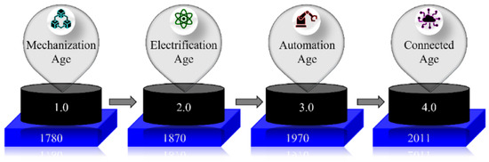
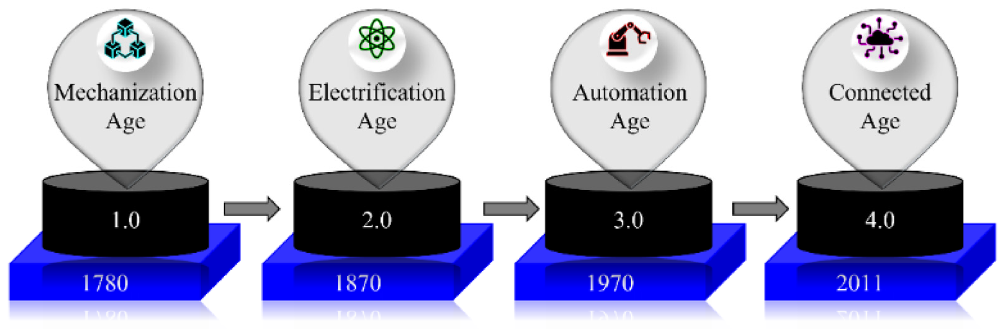
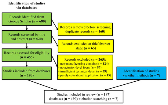
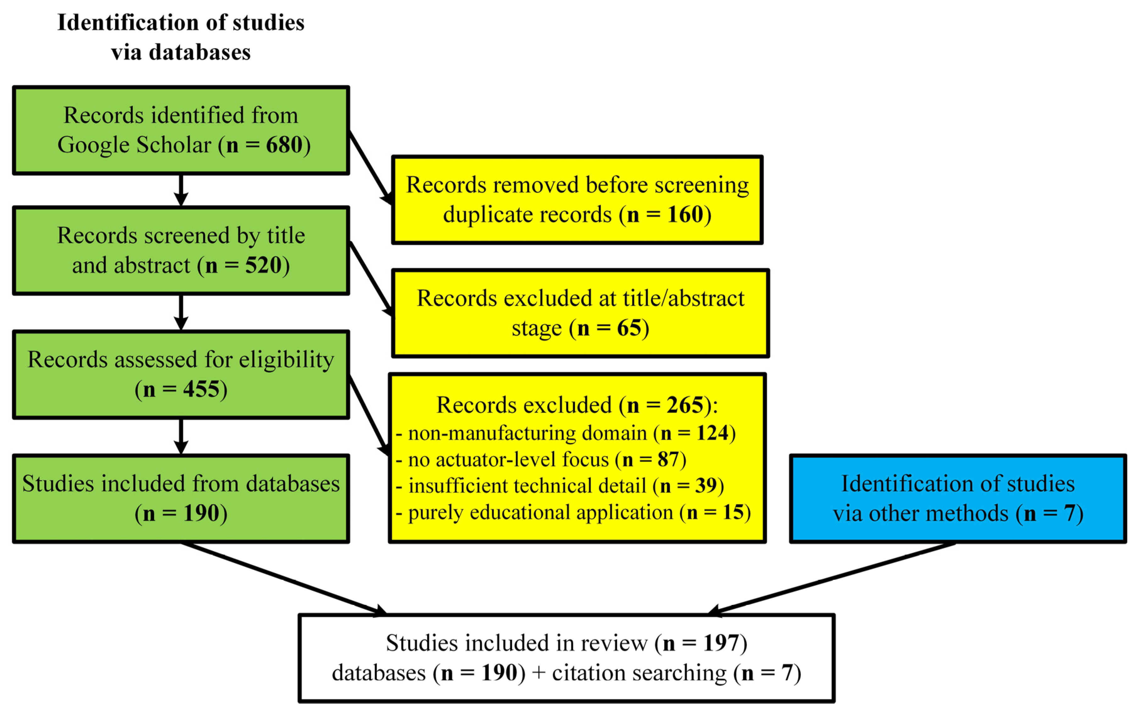
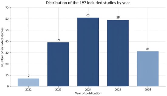
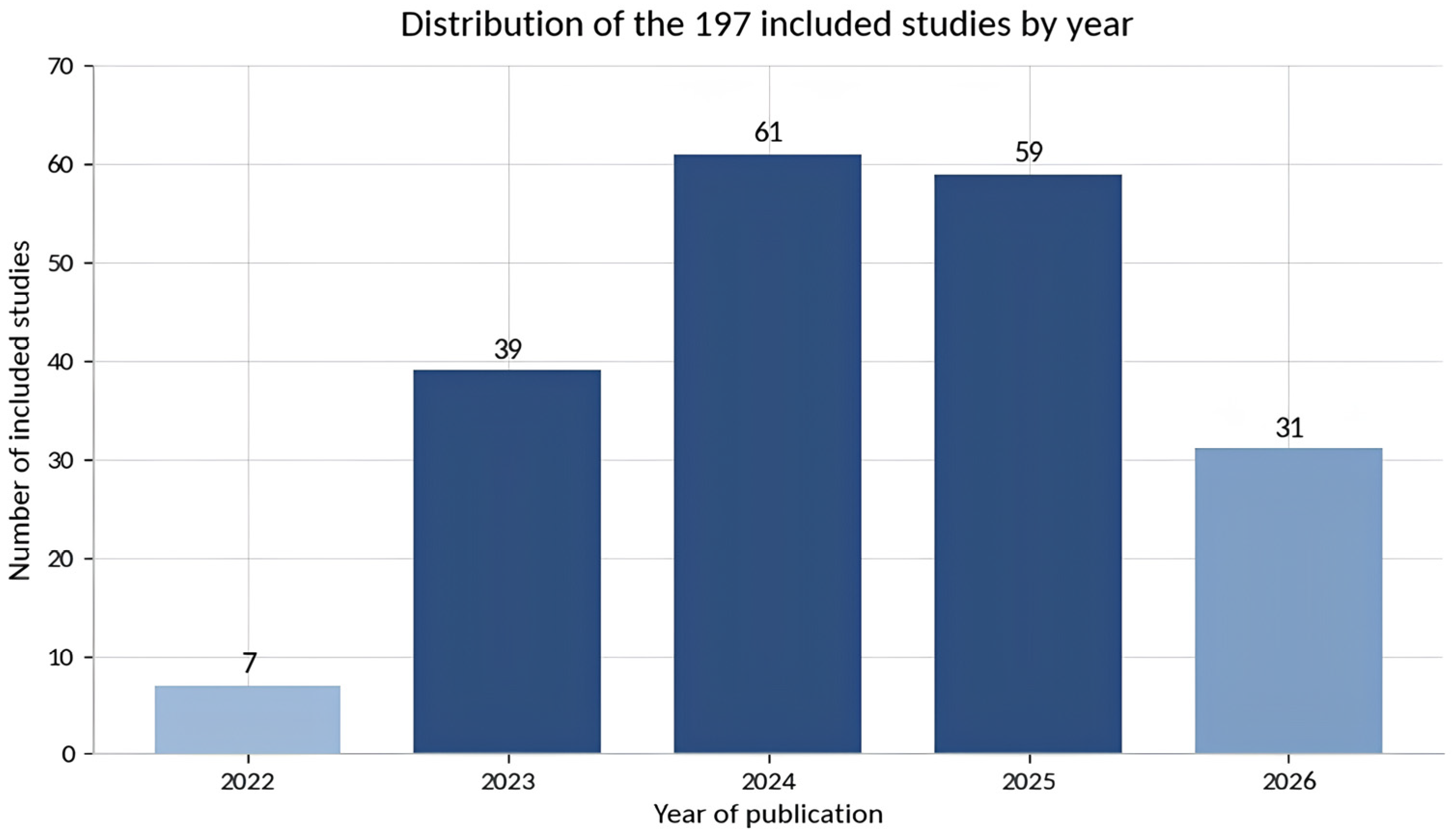
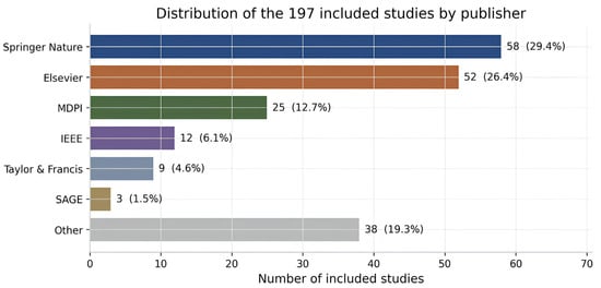
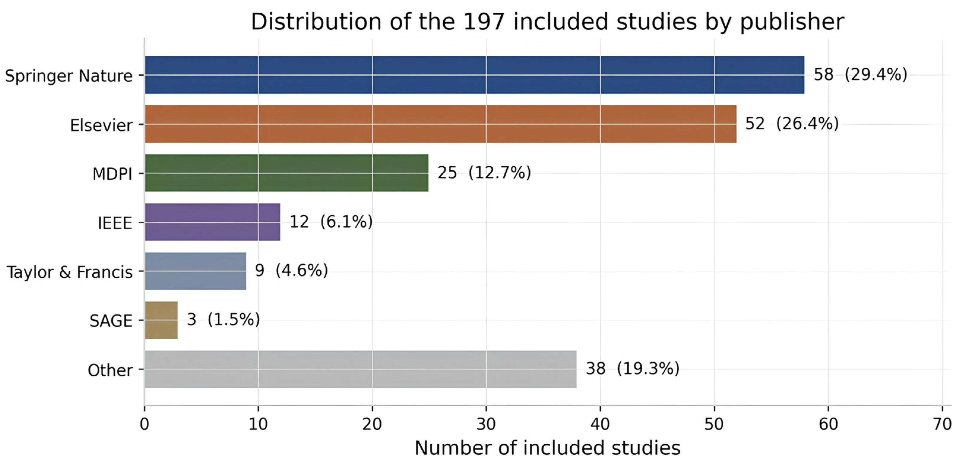
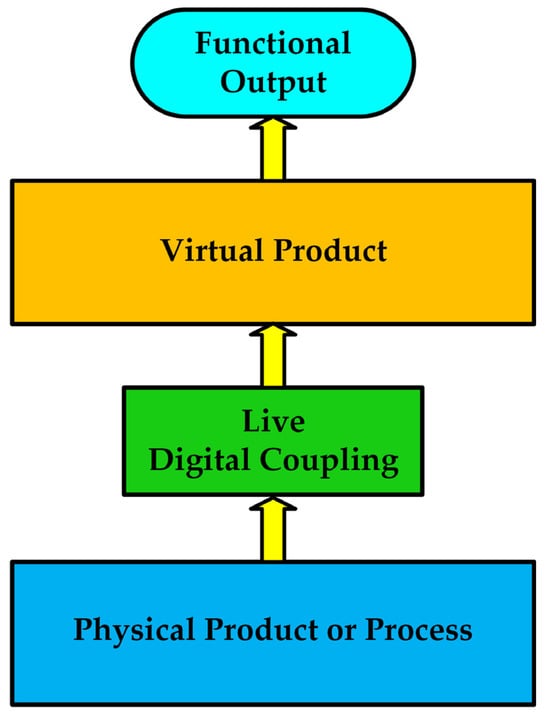
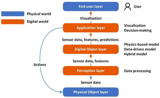
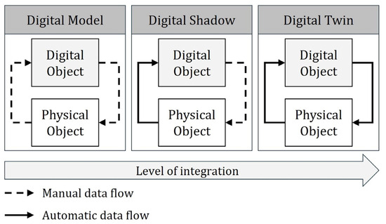
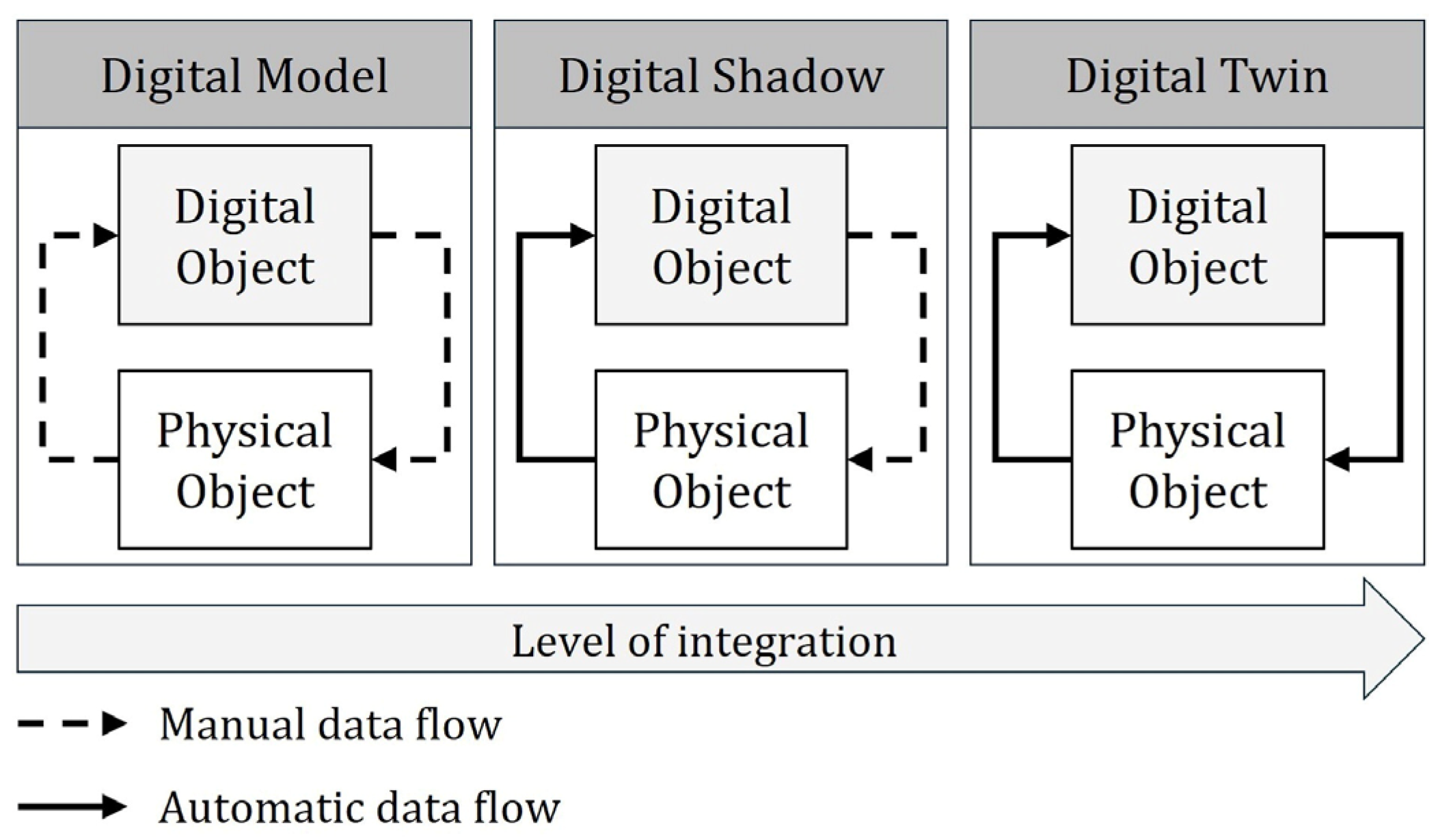
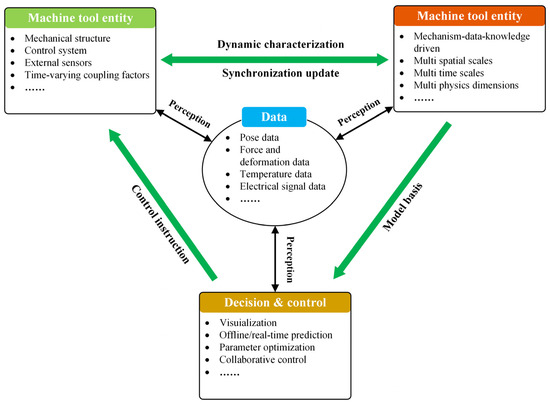
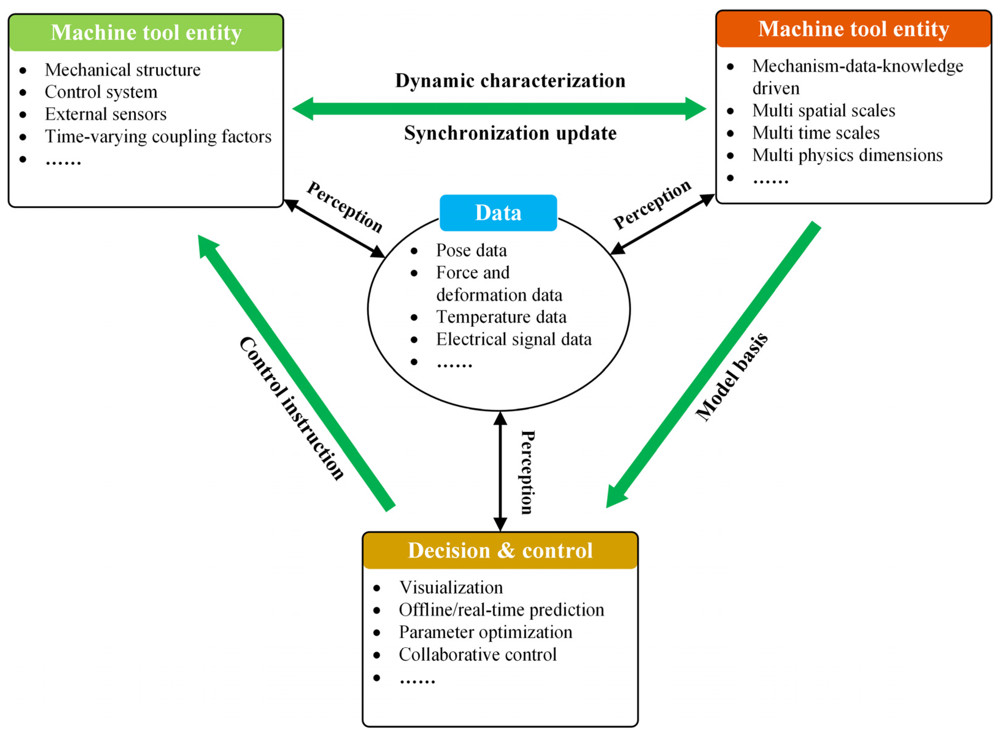
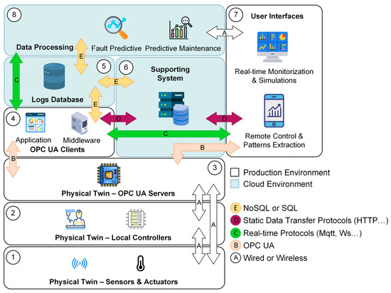
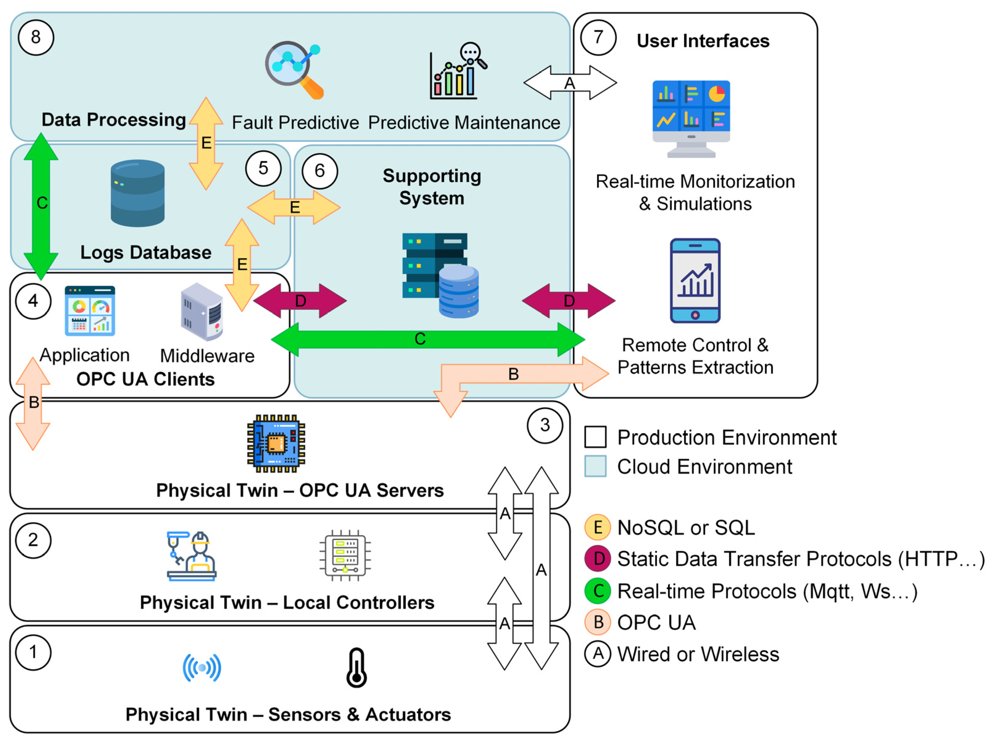
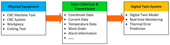
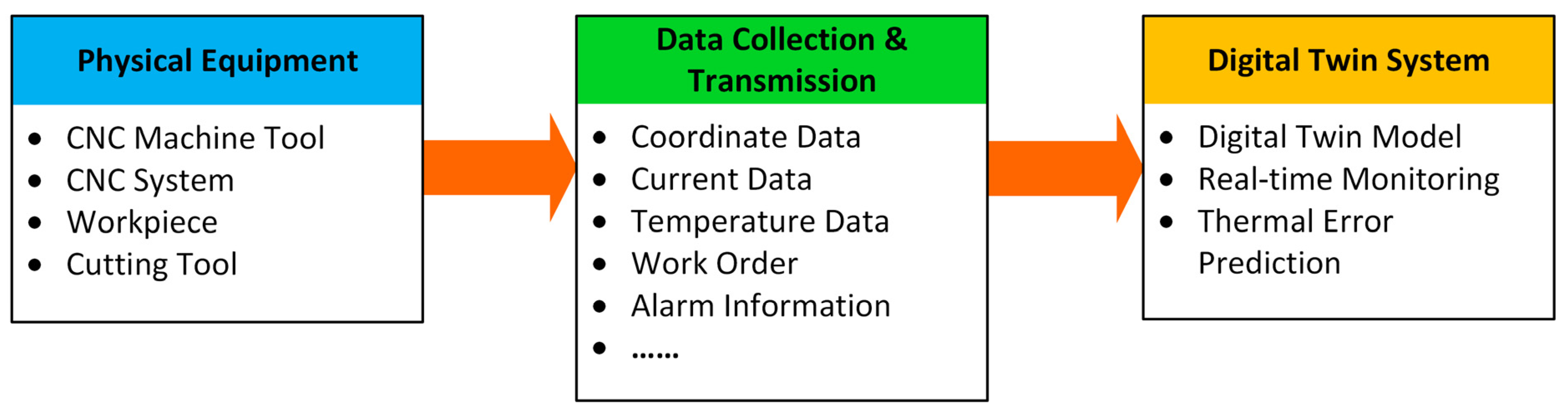
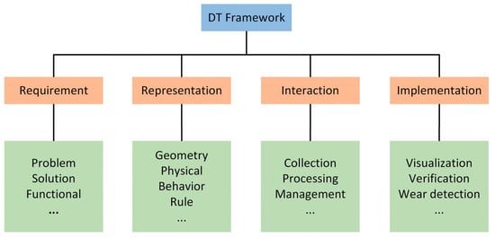
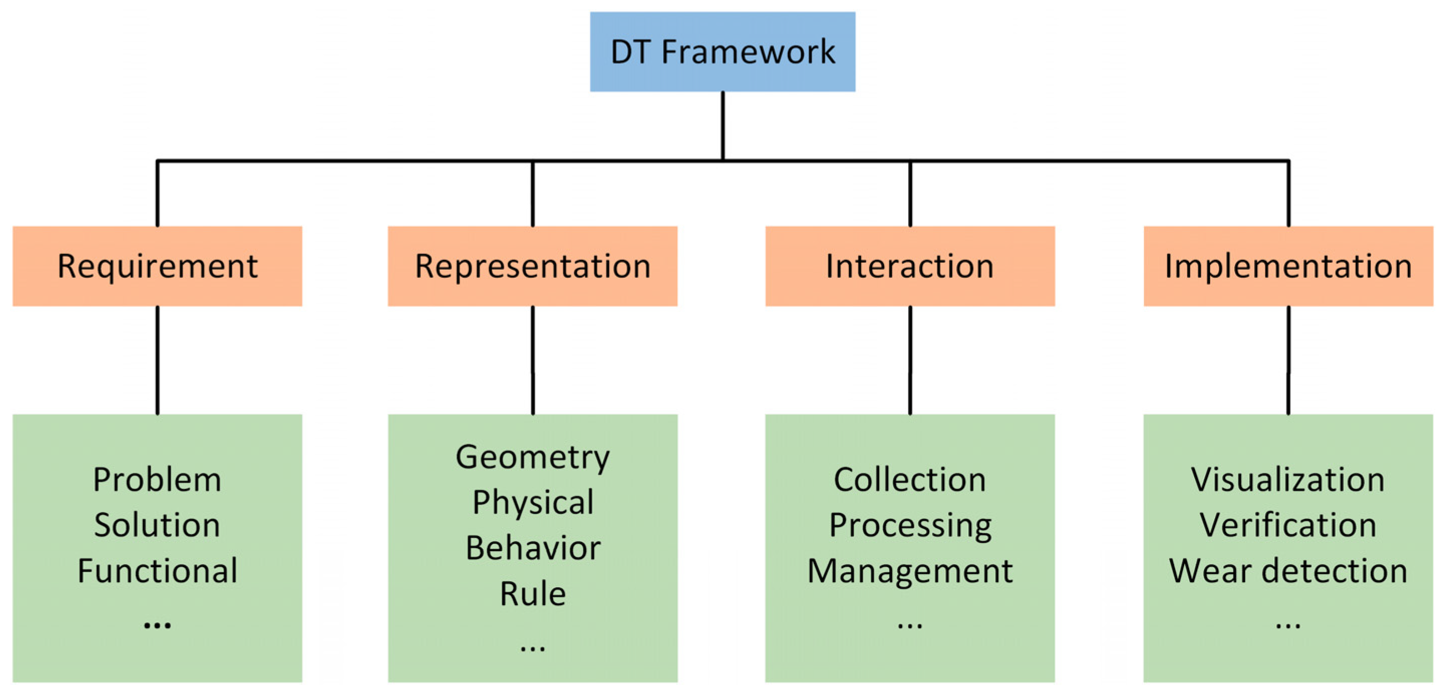
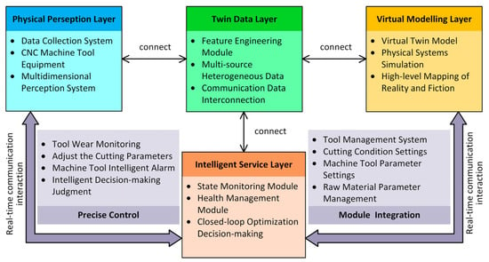
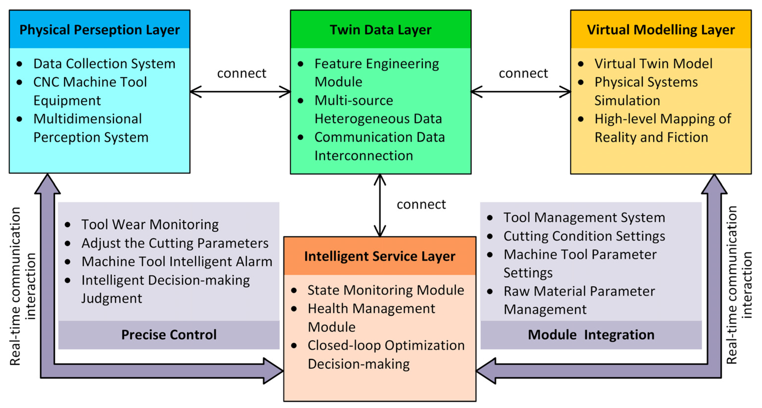
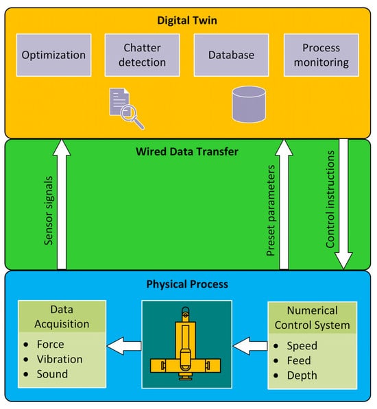
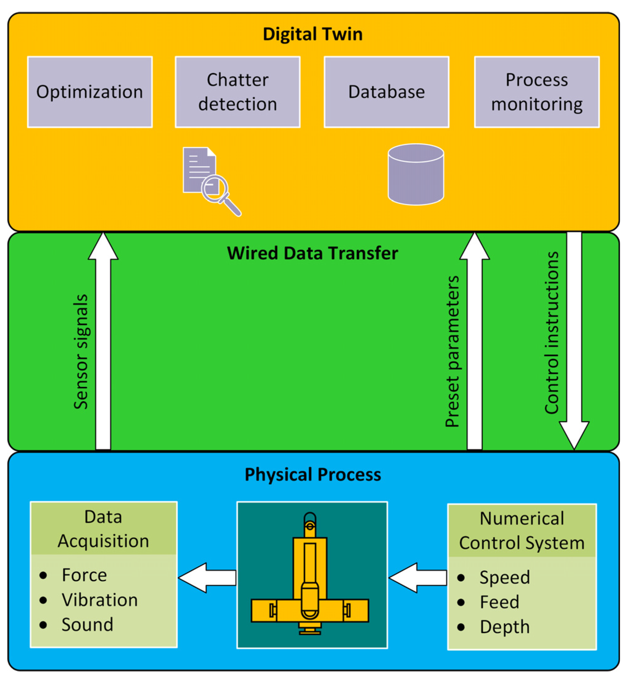
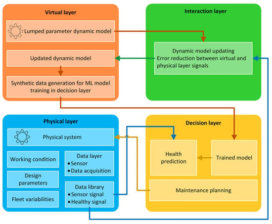
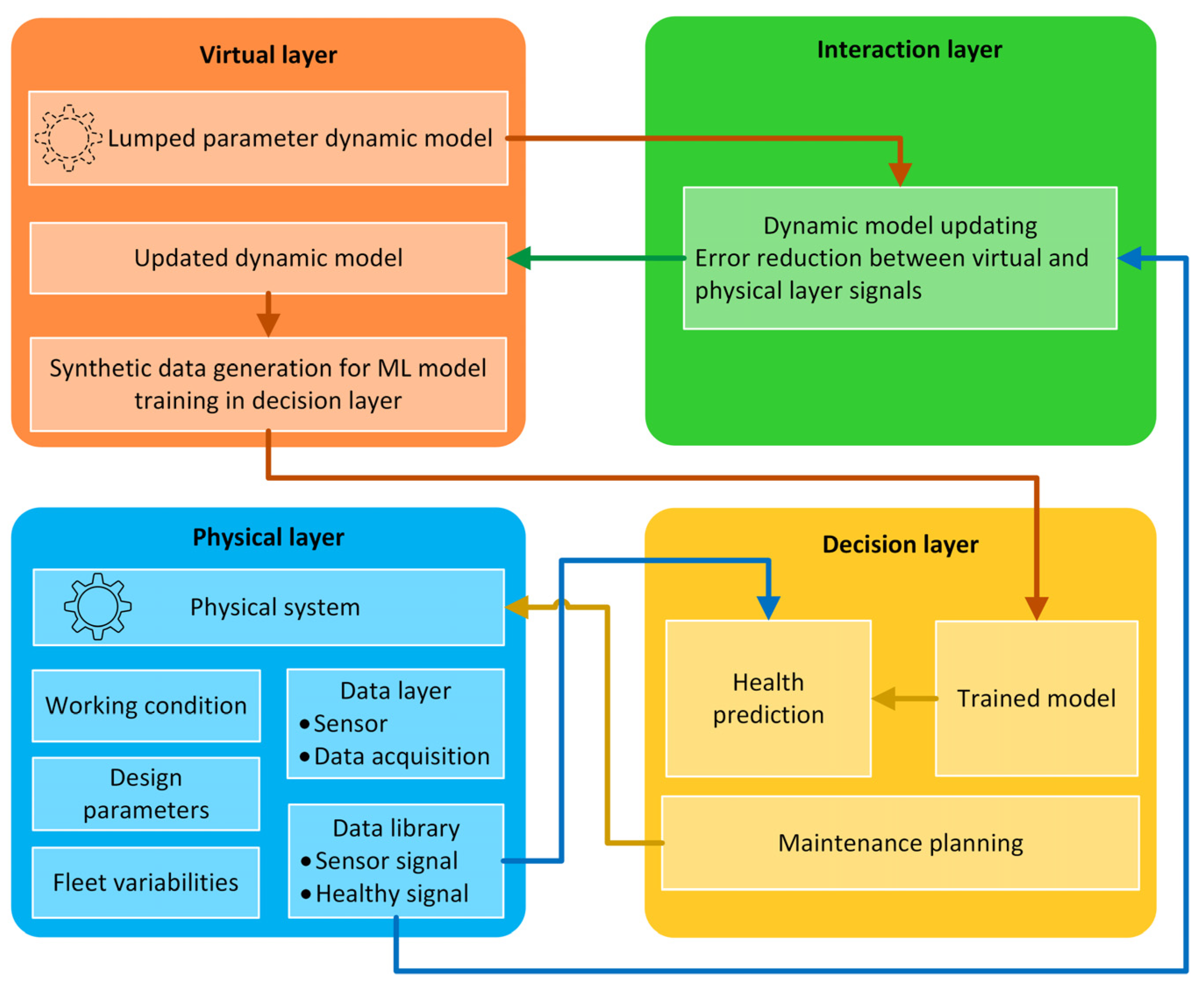
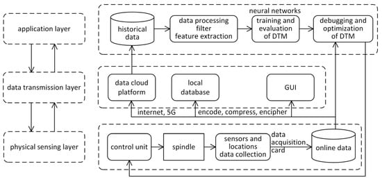
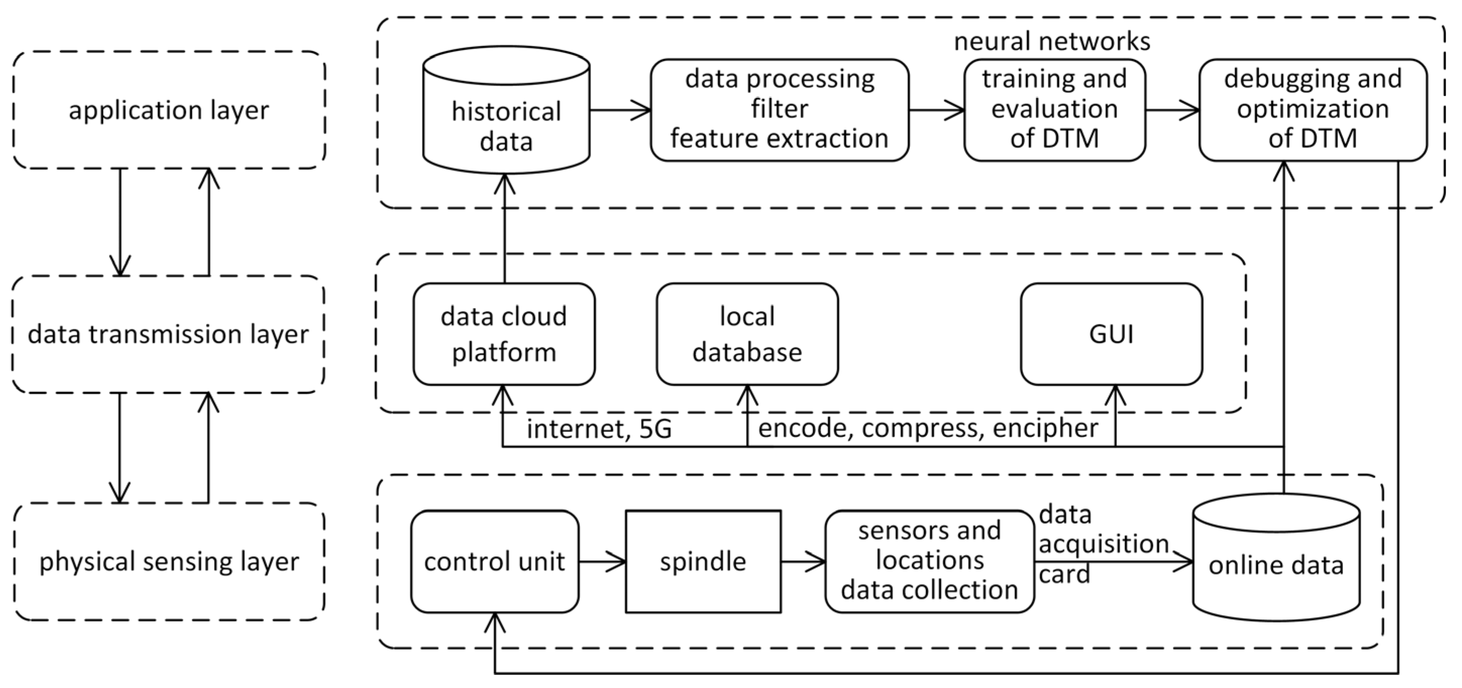
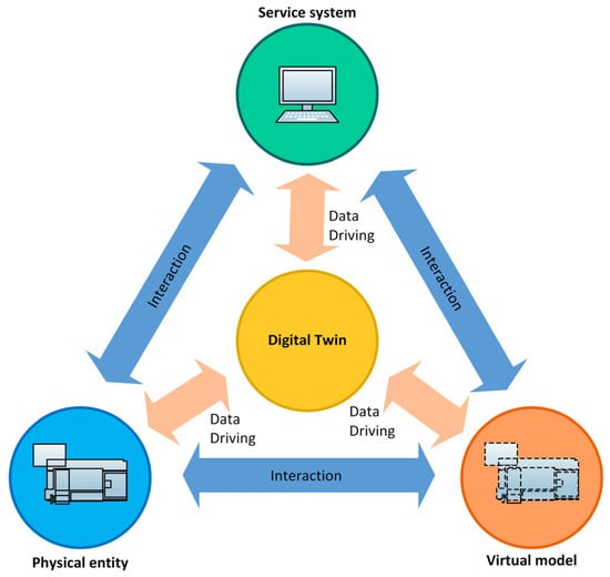
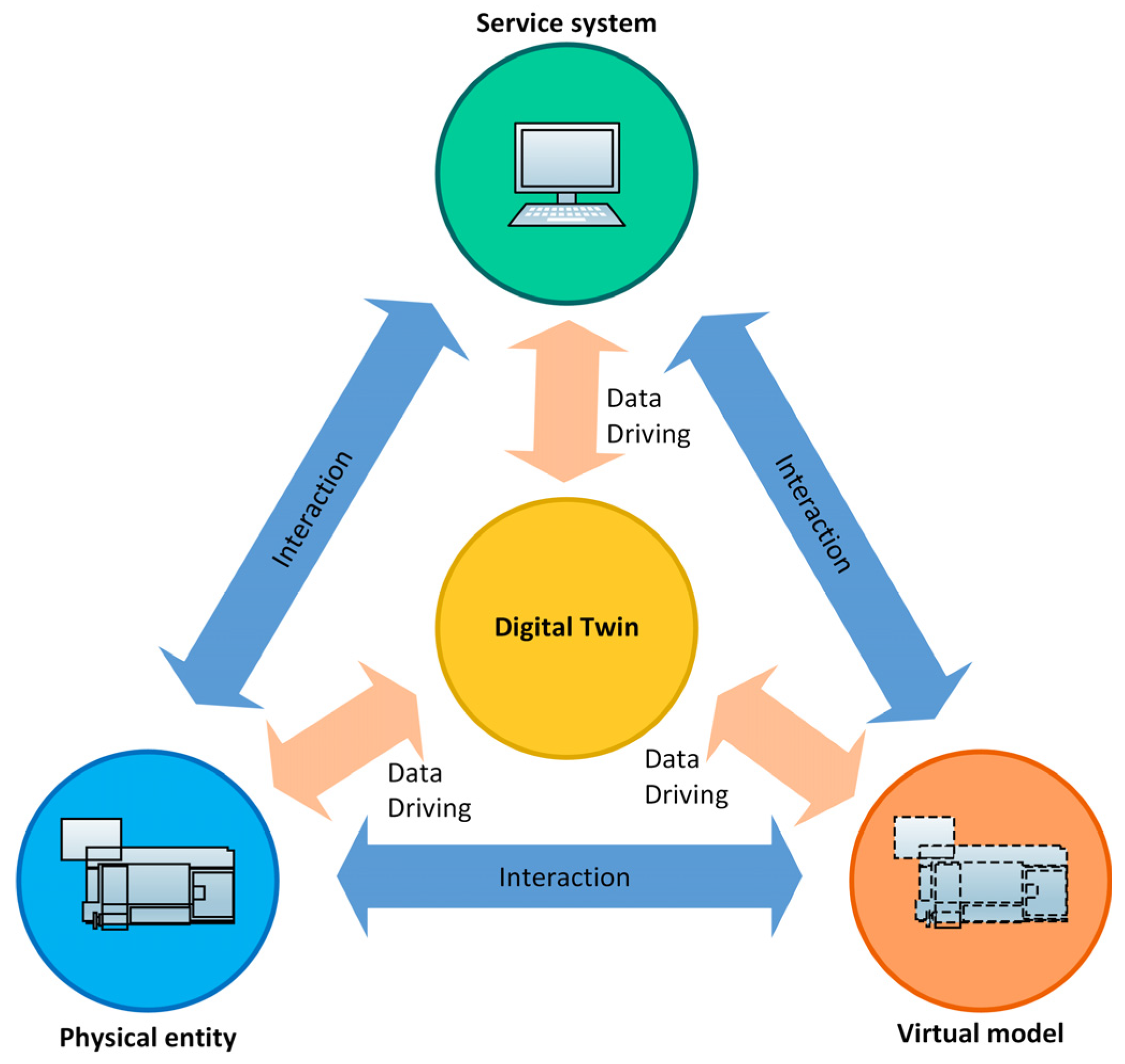
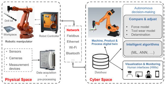
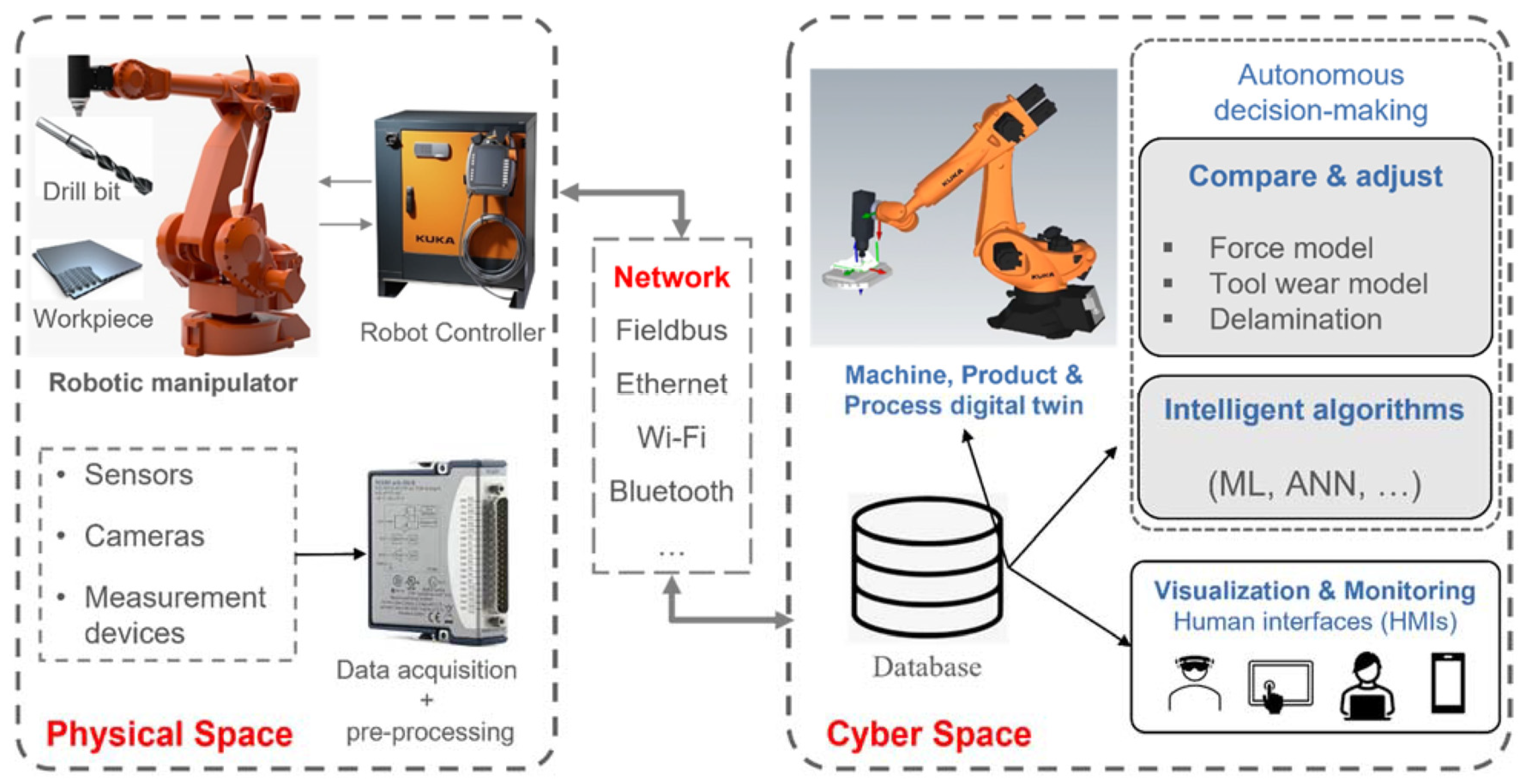

Disclaimer/Publisher’s Note: The statements, opinions and data contained in all publications are solely those of the individual author(s) and contributor(s) and not of MDPI and/or the editor(s). MDPI and/or the editor(s) disclaim responsibility for any injury to people or property resulting from any ideas, methods, instructions or products referred to in the content. |
© 2026 by the authors. Licensee MDPI, Basel, Switzerland. This article is an open access article distributed under the terms and conditions of the Creative Commons Attribution (CC BY) license.