


Abstract
The application of semi-active control systems in lightweight civil engineering structures is still limited even though several studies have shown an improvement in mitigating vibrations under uncertainty scenarios. In comparison with passive systems, a smart device is employed in a Semi-active Tuned Mass Damper (STMD) system to modify its response in real time, usually the damping force. Based on a control law, a degree of adaptability can be achieved in the smart device, leading to the desired tuning between the structure and the STMD to mitigate the vibration induced by the external force, especially when a detuned response between the structure and the control system is caused by external uncertainties. The magneto-rheological (MR) damper is the most common device used for this purpose. Thus, the practical implementation of an STMD in lightweight structures subjected to human-induced vibrations is presented in this paper. An STMD equipped with two sponge MR dampers is developed, modeled, and installed in a fiber-reinforced polymer footbridge, which fulfills the state requirements but exhibits excessive vibrations when its first vertical vibration mode is excited. Numerical simulations are also carried out considering human-structure-STMD interaction. For the analyses, a Mass-Spring-Damper system is used to depict a pedestrian, and the functioning of the MR dampers is represented through a hyperbolic tangent model. Additionally, three different phase control laws are considered for the numerical and experimental implementation of the STMD, namely: (i) an On-Off controller, (ii) a fixed gain controller, and (iii) a variable gain controller. The comparison of the numerical and test results shows that the model used for the MR damper and the STMD are adequate.
1. Introduction
Vibration Serviceability Limit State (VSLS) in footbridges has gained attention in last decades since the optimization of construction processes and materials often leads to slender and lightweight structures. To assess VSLS, external force models are defined in practical guidelines and codes from Europe [1,2,3,4]. Several studies have demonstrated that an excessive conservative prediction may be obtained by employing these load models in moderately lightweight real footbridges [5,6]. Thus, models considering Human-Structure Interaction (HSI) phenomenon have been proposed to achieve accurate vibration results [7]. The modal masses, natural frequencies and damping mechanism of a footbridge are implicitly modified under this approach, given the pedestrians are depicted as dynamic systems acting on the structure.
HSI load models are increasingly being used to calculate the acceleration response of pedestrian structures due to advances in computational capacity [8,9]. These models have even been employed in the design of passive vibration controllers, such as Tuned Mass Dampers (TMDs) [10]. The use of TMD to mitigate human-induced vibrations is a well-known strategy to mitigate high accelerations without adding excessive mass or increasing the stiffness of the structure. Due to the purely mechanical behavior of the TMDs, one disadvantage is their lack of adaptation when the dynamic properties of the structure are modified, producing a detuning behavior between the TMD and the structure, which can be caused by age deterioration, changes in boundary conditions, or level of damping. Therefore, passive TMDs can be upgraded to semi-active TMDs (STMDs) by integrating a properly controlled semi-active device to cope with detuning scenarios [11].
An STMD is an updated version of a TMD, which can modify its mechanical behavior in real time. To achieve the semi-active behavior, the viscous damper can be replaced by a magnethoreologycal (MR) damper [12,13,14]. An MR damper is a semi-active device whose damping force can be continuously adjusted by varying the magnetic field, which is controlled by the current applied to the coil. The device responds to current changes within milliseconds, enabling real-time control. Thus, the detuned problem associated with the lack adaptation can be solved if an adequate control law is implemented. For a system composed of a footbridge and STMD, the phase control law is highly efficient, and it has been studied for many research. Ferreira et al. [15] used an STMD to mitigate vibrations induced by the lock-in effect in footbridges. Wang et al. [16] implemented an STMD with independent variable mass to reduce walking-induced vibrations in bridges. Although the control algorithm corresponded to a switching control strategy, this work represented the first step toward the development of an STMD with both variable mass and variable damping [17]. In this approach, the STMD was employed as an adaptive control device for random crowd-induced vibrations in footbridges, using a phase control algorithm.
One of the main aspects in the integration of an MR damper is the control law. In this study, a phase-based control law is adopted to determine the activation and deactivation instants (On–Off states) of the damping force, commonly referred to in control theory as bang-bang control [18]. One advantage of a phase-based control implementation is the low number of sensors required to determine the structural and STMD states, with only two accelerometers needed. For the MR damper, it means the application of a maximum (On) or minimum (Off) voltage proportional to the current in the coil. However, abrupt switching between two states could produce an overload in the MR damper. Koo et al. [19] studied a control law which depends on the phase of the displacement of the structure and the relative velocity between the structure and the control system. Moutinho et al. [20] modified Koo’s control law in order to achieve a practice implementation, substituting the displacement by the acceleration and neglecting the structure’s velocity with respect to the control system mass velocity. Hanagan [21] proposes a nonlinear control to prevent the overload effect, using a velocity feedback control plus a saturation rule for active control of floor vibrations. The nonlinear control formulated by Hanagan requires a previous evaluation of a gain G, which is designated for a specific set of conditions, and it could lose effectiveness if these conditions change, acting similarly to an On-Off control. Nyawako et al. [22] introduce a variable gain that changes over time, adapting its value based on the actual response of the system to be controlled, based on the maximum voltage support by the MR damper, and the maximum absolute velocity in a previous period evaluated.
This article evaluates the validity of a numerical model of an STMD through the experimental evaluation of an STMD in a lightweight FRP footbridge, which was constructed in the laboratory of structures at the Technical University of Madrid. This footbridge fulfils the ultimate limit state and deformation limit state. However, the VSLS is exceeded. The evaluation of the numerical model included the identification of two RD-1097-1 sponge MR dampers from Lord Corporation [23] through a hyperbolic tangential model. Realistic simulations were performed considering the aforementioned model, the human-structure-actuator interaction, and all the elements necessary for practical implementation, e.g., the low-pass filter, the integrator filter, and the deactivation rule. Finally, the adaptive response of the STMD is governed by a phase control law, which is first combined with one voltage control strategy and subsequently evaluated using a second independent voltage control strategy. This sequential analysis aims to eliminate detuning effects and prevent overload in the MR dampers. The results were obtained under real conditions of uncertainty.
After this introduction, the text is organized as follows. The coupled human-structure system is explained in Section 2. The modeling of the STMD and the experimental identification of MR dampers are presented in Section 3. The performed experimental campaign considering modifications in the dynamic properties of the lightweight footbridge is described in Section 4. A numerical study using different control laws for the STMD is carried out in Section 5. The comparison and discussion of the experimental and numerical results are present in Section 6. Finally, concluding remarks and future works are drafted in Section 7.
2. Pedestrian-Structure Interactive Model
The modeling of the coupled pedestrian-structure system is presented herein. First, the Fiber Reinforced Polymer (FPR) structure used in this work is described together with its model in the frequency domain. Second, the HSI model for a person crossing the footbridge is briefly explained. HSI is a key aspect on the dynamic behavior of lightweight slender footbridges since omitting this phenomenon leads to overestimate significantly human-induced vibrations [24].
2.1. Structure Model
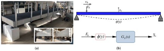
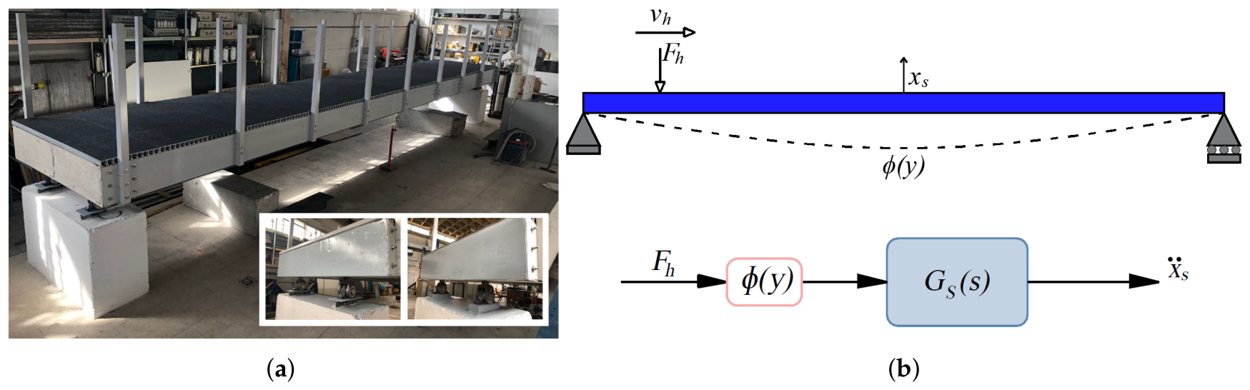
The footbridge is a 10-m long simply supported structure, comprised of FRP elements (see Figure 1a). Three girders with a depth of 300 mm are the principal elements of the structure. They are laterally restrained by 160-mm depth crossbeams, and support the 40-mm height deck panels, which are coated with anti-skid surface. Stainless steel bolts are employed for all the connections among the elements in the structure [25].
Figure 1.
Structure model: (a) Constructed FRP footbridge. (b) Simulink block diagram representation for a moving load.
Based on ref. [26], the footbridge response, a mid-span, can be represented through the Simulink block diagram of Figure 1b, in which is the Transfer Function (TF) of the structure at mid-span and the force is scaled according to each instant position. This block diagram is considered for the first bending vibration mode of the structure, and is derived from the equation of motion of a Single Degree of Freedom (SDOF) (see Equation (1)). Thus, the TF between the structure acceleration at mid-span and an external force applied at the same point is presented in Equation (2).
where , , and x are the acceleration, velocity and vertical displacement, (rad/s) is the Laplace variable, is the vertical displacement of the consider mode shape at the point in which the force is actually applied, is the Laplace transform of the applied force acting on the structure, and is the Laplace transform of the structural acceleration at the control point, where denotes the Laplace transform of the structural vertical displacement. Also, is the effective modal mass, damping coefficient, modal stiffness of the structure, (rad/s) is the structure angular natural frequency, (Hz) is the natural frequency, the damping ratio associated to the structure vibration mode.
In addition, the mode shape, normalized to a maximum value of 1, assumed for the first bending vibration mode is expressed below
where L (m) is the span length of the pedestrian structure. It should be noted that the block diagrams presented throughout the paper represent the simulation implementation rather than a TF-based representation. Thus, , with , is used to scale the pedestrian moving force to mid-span, where its maximum value is reached. For the case of the FRP footbridge, the dynamic properties for the bending vibration mode are as follows: kg, Hz, and % [10].
2.2. Human-Structure Interaction
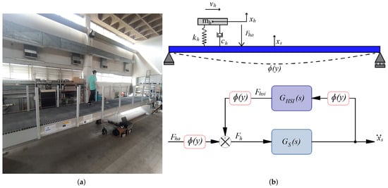
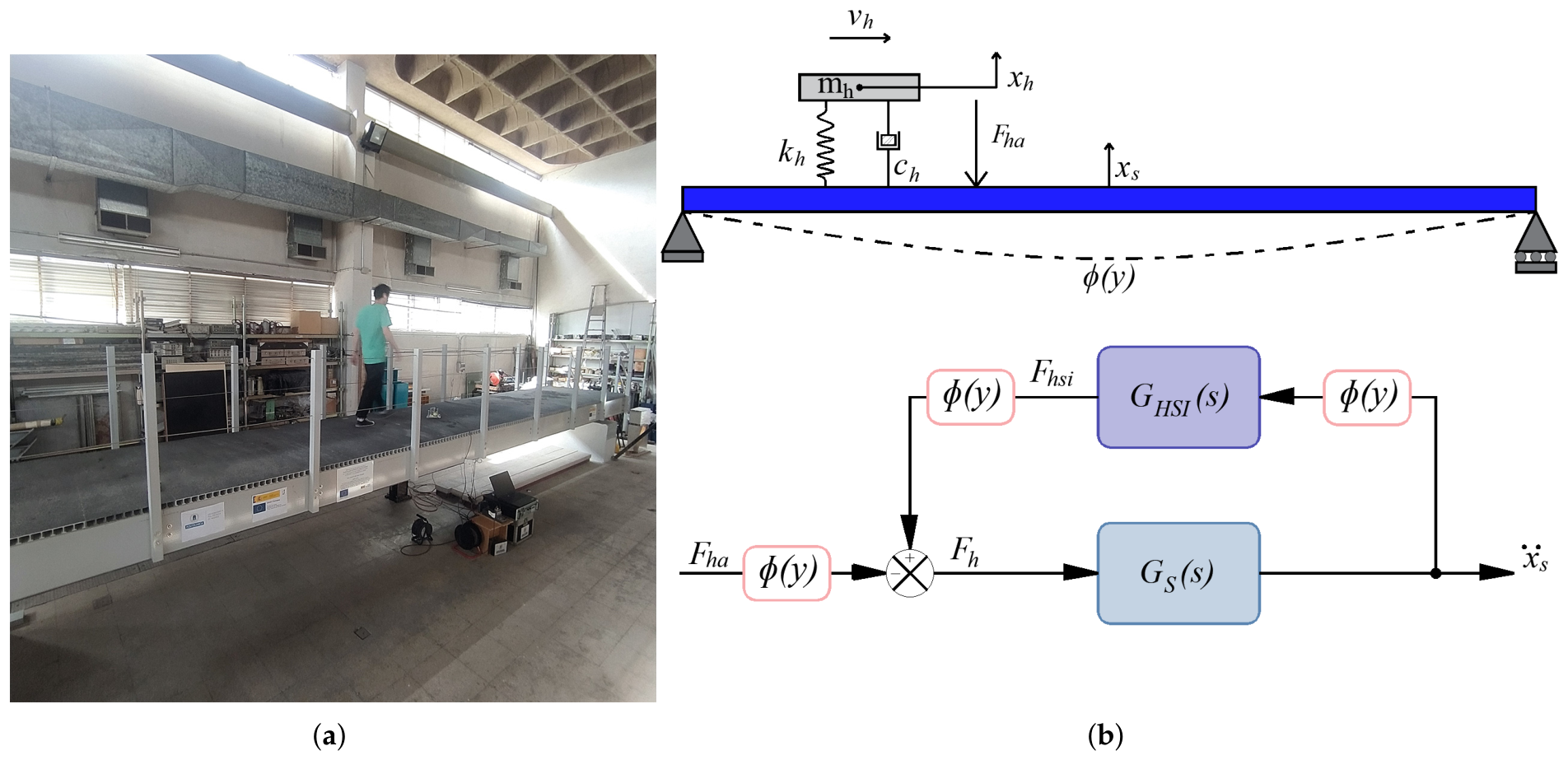
To account for HSI, a pedestrian walking over the footbridge (see Figure 2a) can be represented through a moving Mass-Spring-Damper (MSD) system accompanied by a external harmonic force, as shown in Figure 2b [26]. The mass , natural frequency and damping ratio of the human body are considered in this load model. Additionally, the periodic force , which represents the pedestrian driving force acting on the structure, is defined as follows:
with , where is the total number of harmonics considered, r is the harmonic number, is the static weight of a person, are the vertical dynamic load factors associated to the rth harmonics, is the gait frequency, and is the phase angle of the rth harmonic.
Figure 2.
HSI phenomenon: (a) Pedestrian crossing the bridge. (b) Simulink block diagram representation.
The block diagram presented in Figure 2b can be employed to model the interaction phenomenon in the Laplace domain [26]. The TF shown in Equation (2) and the mode shape presented in Equation (3) are used in this diagram. Additionally, a TF between the transmitted interaction force () applied at location y and the structure acceleration at midspan is employed. This TF is derived from equation of motion (5) and (6), which represents the force balance between human and structure. Thus, is described by the Equation (7).
where , , , and are the damping coefficient, modal stiffness, and the angular natural frequency of the human body.
The derivation of the TFs and the construction of the block diagrams mentioned in this section are fully described in ref. [26].
3. Semi-Active TMD
The STMD for a pedestrian-structure interactive system is defined in this section. In addition, the identification of the Sponge MR dampers employed for the implementation is presented.
3.1. Semi-Active Control Model
Since the STMD performs a non-linear behavior, it is not possible to define a closed-loop TF, including the control system and the HSI phenomenon. Thus, the human-structure-STMD system needs to be analyzed in the time domain. The equations of motion that govern the behavior of this system are given as follows:
is the transmitted force by the STMD and is the external resulting force produced by the human loading. The force is defined from Equation (8) as follows:
The subindex t is associated with the mechanical parameter of the STMD. Thus, is the inert mass, is the damping coefficient of the MR damper, which can be modified in real-time, and is the stiffness.
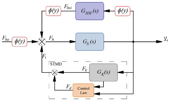
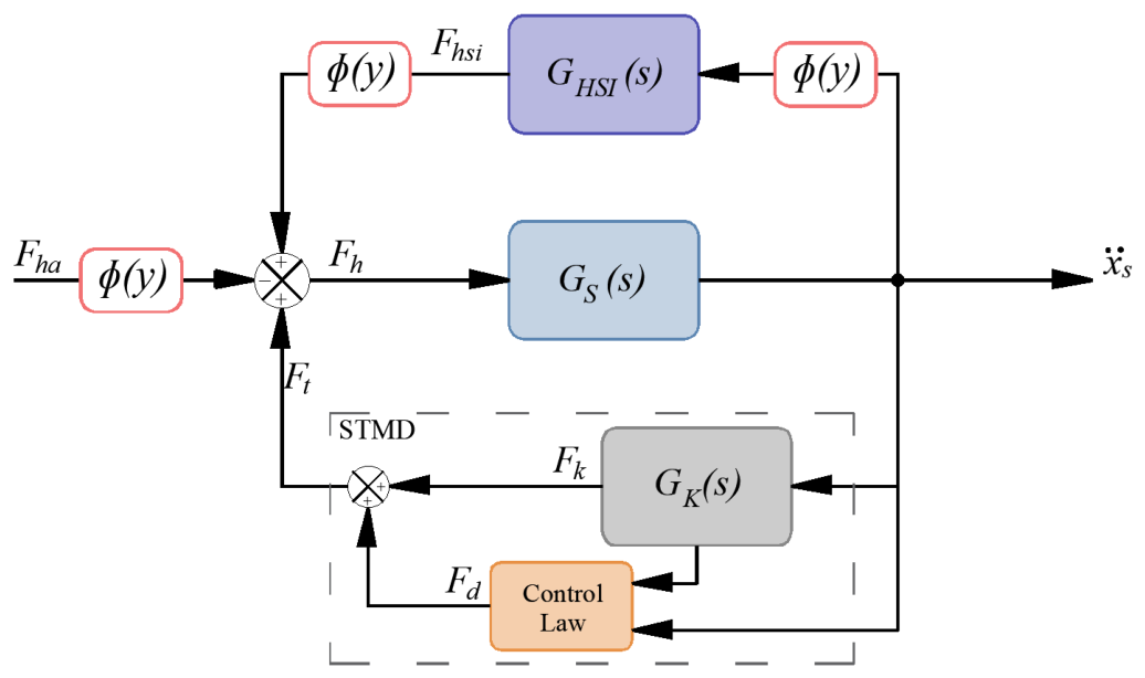
Figure 3 shows the block diagram for the HSI model with an STMD in the Laplace domain. The transmitted force is obtained as the sum of the elastic force (), purely passive—linear and represented by its TF —and damper force from the MR damper (), which is nonlinear and governed by a control law that depends on the responses of the structure and the inertial mass. The TF that represent with respect the structure’s acceleration is derived from Equation (8); neglecting the term , it takes the following expression:
Figure 3.
Simulink block diagram of the HSI and STMD models.
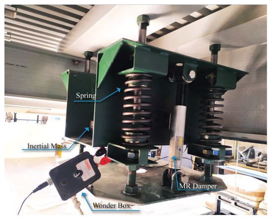
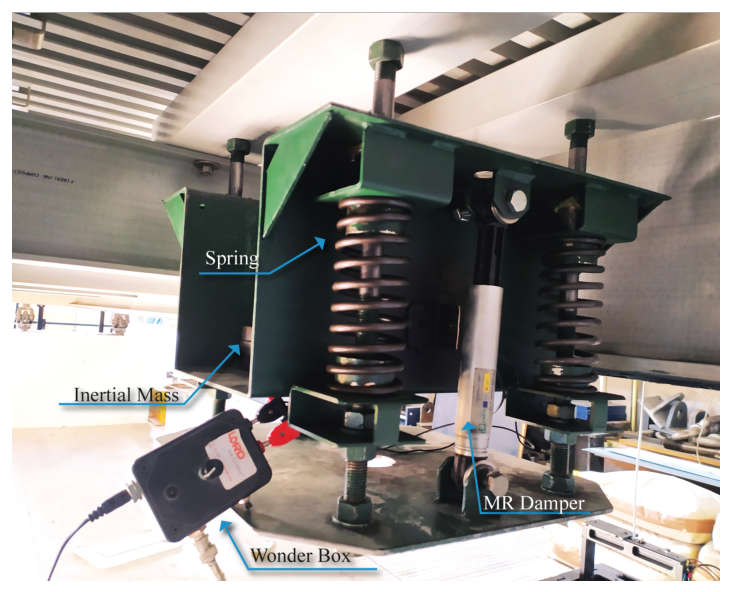
The STMD installed in the footbridge is presented in Figure 4. The controller is comprised of: 26-kg, four springs (each element provide a stiffness of 14 kN/m), and two Sponge RD-1097-1 MR dampers from Lord Corporation [23], while two PCB B12-type accelerometers were employed to obtain information from the footbridge and inertial mass [27]. The parameters and aforementioned have been selected to achieve a tuned frequency of 7.47 Hz.
Figure 4.
STMD installed in the FRP footbridge.
3.2. Experimental Identification of the MR Damper
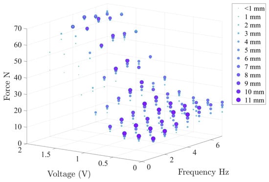
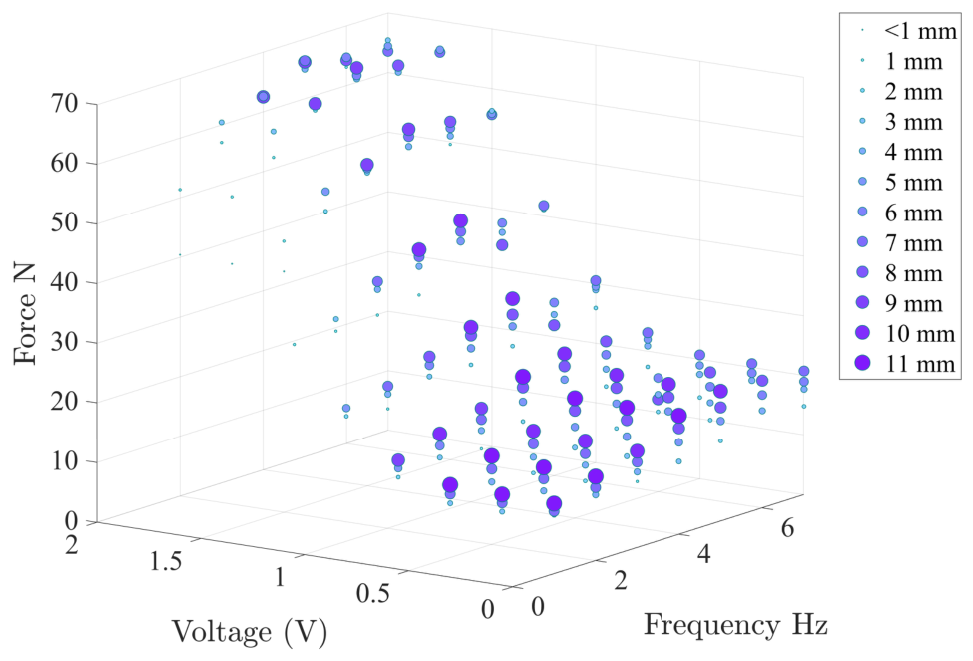
To identify the main characteristics of the sponge MR damper, 194 tests were carried out imposing employing a sinusoidal force by a dynamic hydraulic jack. Each test signal combined seven frequencies from 1 to 7 Hz, nine different voltages from 0 to 2 V with an increasing step of 0.25 V, twelve displacement amplitudes (from 0.5 to 11 mm) depending on the frequency of the signal. For high-frequency testing, the displacement amplitude is low because the hydraulic jack does not allow large displacements under high velocity.
Figure 5 summarizes the maximum absolute force registered for each test developed based on the combination of frequency, displacement, and voltage. This information, and the force-time response registered are the source for the numerical identification of the Sponge MR damper. A hyperbolic Tangential model proposed by Kwok et al. [28] was used to identify the hysteretic variable z in the MR damper identification process. The hyperbolic Tangential model is described by the following equation:
Figure 5.
Summary of the tests performed on the Sponge MR damper (the sizes of the point indicate the test amplitude).
The identification process is formulated as an optimization problem aimed at minimizing the mean squared error (MSE) between the numerical force from Equation (12) and the experimental force from each test. The minimum value of MSE is obtained by adjusting the parameters , , , , and ( is assumed equal to zero), using a Genetic Algorithm (GA) implemented in MATLAB [29]. The GA consider an initial population of 50 individuals (parameter vectors with the design variables) that randomly are created and iteratively modified according to the natural selection rules of the algorithm, which are based on the selection, crossover, and mutation mechanisms. The selection mechanism selects parents from the current population to create the next generation. Once the parents have been selected, the crossover and mutation mechanisms create the new population. The fraction of the population created in the next generation by the crossover function is 0.8. The mutation introduces small random changes in individuals, providing genetic diversity and enabling the genetic algorithm to explore a broader search space [30].
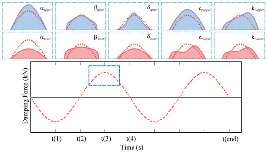
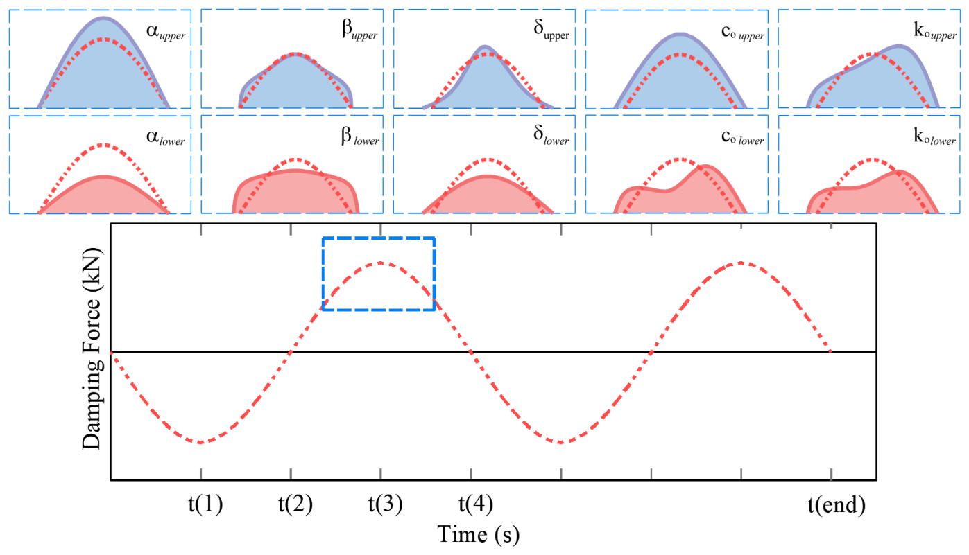
Figure 6 schematically illustrates the damping force response of the MR damper (dashed red line) and how this response changes for higher (solid lavender blue line) or lower (solid coral red line) values in the hyperbolic tangent model parameters in the maximum amplitude zone, e.g., controls directly the amplitude of the growing zone; expand the zone and reduce the peak for lower values; reduce the width and generate a peak for an upper value, while a lower value flatten the peak; increase the peak with simultaneous increment on the width, for a lower value, the peak decrease considerable and produce two parallel peaks; reproduce an ascendant slope from left to right from lower to upper values.
Figure 6.
Sensitivity of the damping force response to parameter variations in the hyperbolic tangential model.
All of these parameters are identified, not only as dependencies on the voltage (V), but also on the amplitude and frequency of the excitation force. Thus, based on the work developed by Kwok et al. [28], amplitude and frequency are considered through the term of maximum velocity (). The parameters are defined with a V-dependent, -dependent, or -V-dependent polynomial functions.
The identified MR damper based on the above equations is considered in the numerical study presented in Section 5.
3.3. Phase Control Laws
Phase-control-based strategies aim to control the relative movement between the controller and the structure to be controlled. These are non-model-based strategies in which the complete state of both controller and structure is not needed for their application. Another important advantage is that the non-linear behavior of the damper does not affect the realization of control law. The first phase control was introduced in the power flow theory proposed by Soong and Dargush [31] to control the phase of a TMD. To achieve optimal performance, the TMD must develop a resonant response. Actually, in resonance, for a low-damped TMD (assuming the TMD’s damping is negligible) the phase between the relative displacement of the inertial mass and the structure displacement is 90°. Thus, the TMD’s response acts in the opposite direction to the structure’s response, controlling or canceling out its vibrational behavior. This occurs because the force transmitted by the TMD and the excitation force are 180° delay.
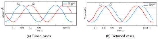
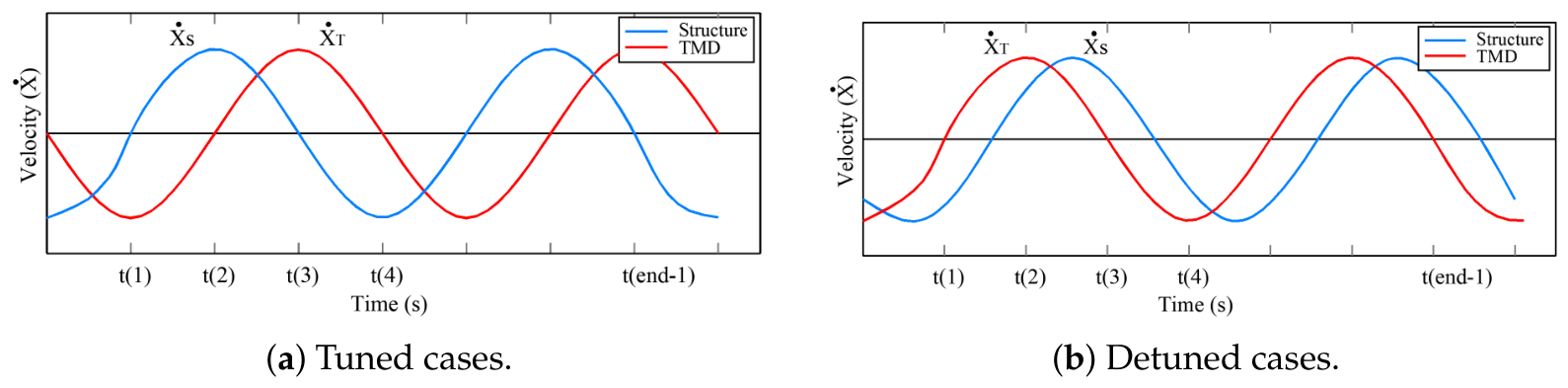
Figure 7 shows the velocity response for a structure and the relative velocity of a TMD for a tuned and detuned case. When the velocity of the structure is zero, and the TMD velocity is maximum, the TMD is tuned (Figure 7a). However, as the phase relationship is lost, the TMD loses effectiveness and is considered detuned (Figure 7b). The phase control law aims to adjust the movements of the controller’s inertial mass to suppress the detuning effects. In that case, the control strategy acts over the MR damper, stopping the inertial mass movement to produce the delay required to achieve the controlled phase of 90°.
Figure 7.
Tuned and detuned situation for a phase control.
Koo et al. [19] used the skyhook and groundhook concepts [32] to define On-Off controllers for TMD. Even though the On-Off is not initially described as a phase control, the controller analyzes the response in terms of the velocity of the structure and relative velocity of the control device. The control law used in an STMD analyzes the velocity and relative velocity , where is the velocity of the main structure, and is the velocity of the TMD. Koo defines the control strategy in terms of velocity as a Velocity-Based Groundhook (VBG) as follows:
The VBG can be analyzed in terms of displacement through the Displacement-Based Groundhook as follows:
The variable is the displacement of the main structure, while On-Off states correspond to the application of minimum and maximum voltage/current on the MR Damper. The On-Off control is known in the control theory as the Bang-bang control [18] since it switches abruptly between two states.
Furthermore, Koo also presents a continuous control, which changes the damping level between the On and Off states. The control law may be formulated as velocity or displacement feedback as follows:
in which G is a fixed control gain.
Continuous control could produce overload in the MR damper because the control has no boundaries. Hanagan [21] proposed a nonlinear control for active control of floor vibrations, which prevents the overload effect, that is, a velocity feedback control plus a saturation rule. This nonlinear control is given by the following:
where and are the limits of the voltage to avoid the overloading effect.
Nonlinear control requires a previous evaluation to obtain the gain (G). This G is obtained and adapted for a specific set of conditions. However, if these conditions change, the nonlinear control will not be effective and could adopt a behavior similar to an On-Off control.
A variable gain control offers a solution for the previous evaluation to define G, transforming its variable from constant to variable with time. Nyawako et al. [22] defines variable gain as follows:
is the maximum absolute velocity in a previous period (T). In this sense, gain G will change over time adapting its value based on the actual response of the system to be controlled.
Barrera-Vargas et al. [30] proposed a phase control law for a lightweight structure with an STMD, based on the skyhook and groundhook concepts presented by Koo et al. [19] and the simplification proposed by Moutihno et al. [20]. The control law takes into account the acceleration of the structure and relative velocity between the structure and the inertial mass without neglecting the structure’s velocity as Moutinho proposed.
The equations of the phase control law proposed by the authors are presented below as follows:
where and are acceleration and velocity; subindices s and t represent the structure and the controller. and are the minimum and maximum damping coefficients, which means applying minimum () and maximum () voltages to the Wonder Box (see Figure 4). The Wonder Box transforms the voltage into current, which is then applied to the MR damper. is the saturation value for the force, which corresponds to the maximum damping force reached for the MR damper considered. The purpose of the phase law is to keep the inertial mass motion as close as possible to the tuned phase.
In order to avoid an abrupt switching between and (On-Off) states of the damping force in the MR damper, the effectiveness of two voltage controllers, based on a fixed- and variable-gain, is assessed.
4. Experimental Implementation
This section presents the experimental campaign conducted to validate the numerical simulation of the STMD model (Section 5) and to evaluate the performance of the different proposed voltage-control strategies. The effectiveness of the STMD concept under controlled and uncontrolled conditions has been previously demonstrated by Barrera-Vargas et al. [30]. The STMD implementation considers the phase-control law together with the three voltage control strategies defined in the previous section.
4.1. Description of the Set-Up
Three scenarios were considered to evaluate experimentally the performance of the STMD when the modal parameters of the footbridge are modified. The scenarios are listed next:
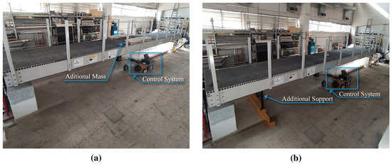
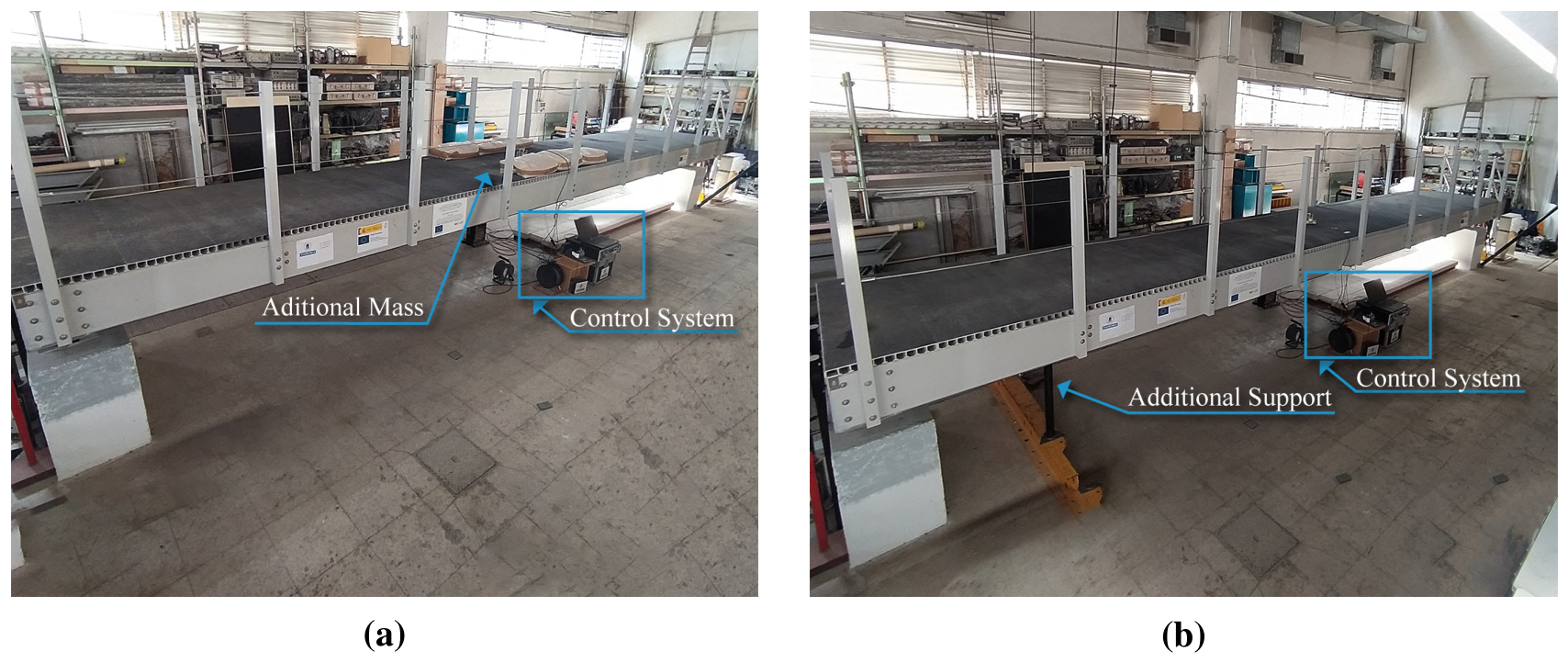
- A ‘detuned below’ scenario: the fundamental frequency of the bridge was modified to a lower value by increasing the structure mass. Six sandbags of 20 kg were placed on the deck as shown in Figure 8a, so the fundamental frequency of the FRP bridge decreased from 7.47 Hz to 6.20 Hz. This case may occur if a group of pedestrians stands on the structure.
- An ‘Unmodified’ scenario: the fundamental frequency of the base structure remains at 7.47 Hz.
- A ‘detuned above’ scenario: an additional support was incorporated near one of the edges of the structure, as presented in Figure 8b. Hence, the stiffness of the footbridge was increased, modifying the natural frequency from 7.47 Hz to 8.80 Hz. This situation may arise, for instance, when the support deteriorates and restricts the movement of the footbridge, thereby increasing its natural frequencies.
Figure 8.
Modifications on the structure: (a) “Detuned below” scenario, and (b) “Detuned above” scenario.
For the first scenario (‘detuned below’), the pedestrian crossed the bridge (see Figure 2a) at a gait frequency of 2.06 Hz, aiming to synchronize the third harmonic of the action with the structure frequency of 6.20 Hz. For the ‘unmodified’ case, a person was asked to walk at a frequency of 1.85 Hz. Thus, the fourth harmonic of the pedestrian excited resonantly the unmodified vibrating system. For the ‘detuned above’ experiment, the pedestrian walked with a gait frequency of 2.20 Hz, seeking to synchronize the pedestrian’s fourth harmonic with the fundamental frequency of 8.80 Hz. The weight of the test subject involved in all tests was 65 kg, and a metronome was employed to control the gait frequency during the different tests.
4.2. Footbridge Dynamic Response
The dynamic response of the footbridge was measured using an accelerometer placed at midspan underneath the deck. For each scenario, the tests were carried out on the structure equipped with a
- TMD tuned to a frequency of 7.47 Hz. This was performed using the MR dampers in the off state to achieve a passive behavior. The MR dampers were not connected to the supply energy.
- STMD with a phase control On-Off. The voltage control was kept between V and V.
- STMD with a phase control with fixed control gain G.
- STMD with a phase control with variable control gain .
Therefore, 12 experiments were performed in total. The duration of each test was 60 s, so the pedestrian could cross the footbridge several times in every experiment. Just the control laws that modify the behavior of the MR dampers are considered to adapt the response of the STMD during the tests.
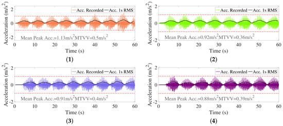
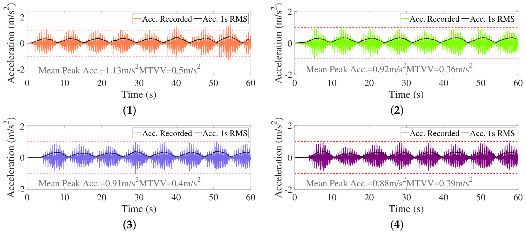
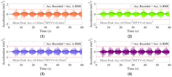
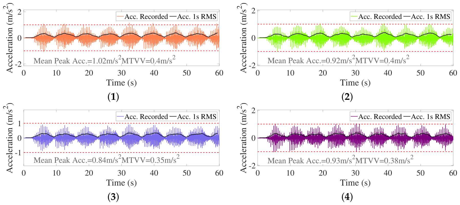
Figure 9, Figure 10 and Figure 11 display the recorded measurements of the walking excitation on the structure for each setup and controller. Each plot shows the time history and the moving Root-Mean-Square (RMS) value computed from a 1-s time window. The mean peak value of all the crossings and the maximum RMS value (known as Maximum Transient Vibration Value, MTVV) are shown at the bottom of each plot. Figure 9 displays the collected data during the tests in the ‘detuned below’ scenario. Considering the calculated MTVVs of the signals, the STMD On-Off was the control strategy that exhibited the best performance. On the other hand, the worst behavior was obtained from the TMD. This result was expected since the passive controller is tuned to a different frequency of the footbridge. Based on the Hivoss Guidelines [33], the comfort level in the structure for all the experiments was medium since the values of MTVV were between 0.5 m/s2 and 1.0 m/s2.
Figure 9.
‘Detuned below’ scenario—Acceleration response of the footbridge with a (1) TMD, (2) STMD On-Off, (3) STMD Gain G, and (4) STMD Gain .
Figure 10.
‘Unmodified’ scenario—Acceleration response of the footbridge with a: (1) TMD, (2) STMD On-Off, (3) STMD Gain G, and (4) STMD Gain .
Figure 11.
‘Detuned above’ scenario—Acceleration response of the footbridge with a: (1) TMD, (2) STMD On-Off, (3) STMD Gain G, and (4) STMD Gain .
The footbridge response for the ‘unmodified’ scenario is shown in Figure 10, where it can be seen that the STMD On-Off was again the best controller to mitigate the human-induced vibrations. The less effective device in this scenario was the STMD with fixed gain G, and the performance of the TMD improved due to the controller was tuned to the bridge fundamental frequency. The comfort level in the structure for the forth tests was maximum since the values of MTVV were under 0.5 m/s2.
Figure 11 presents the recorded measurements of the experiments for the ‘detuned above’ scenario. In terms of the values of MTVV, the comfort level in the structure for the first, second, and fourth experiments was medium, whereas for the third one was maximum. This means that the STMD with fixed gain G again outperformed the other control devices. The TMD and the STMD with On-Off control law exhibited similar effectiveness to reduce the vibration levels in the FRP structure.
In Figure 10, the peak acceleration values do not exceed the medium comfort limit of 1 m/s2. However, in Figure 9 and Figure 11, the TMD leads to a maximum acceleration higher than 1 m/s2. At the same time, the STMD presents peak acceleration values exceeding the medium comfort level. A summary of the computed MTVV for all the 12 experiments is presented in Table 1.
Table 1.
Computed MTVV(m/s2) from the measured response of the FRP footbridge.
4.3. Comparison of Results
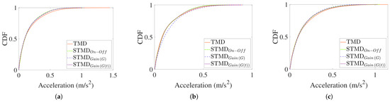
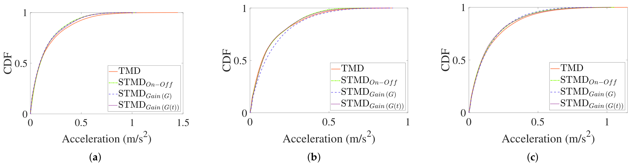
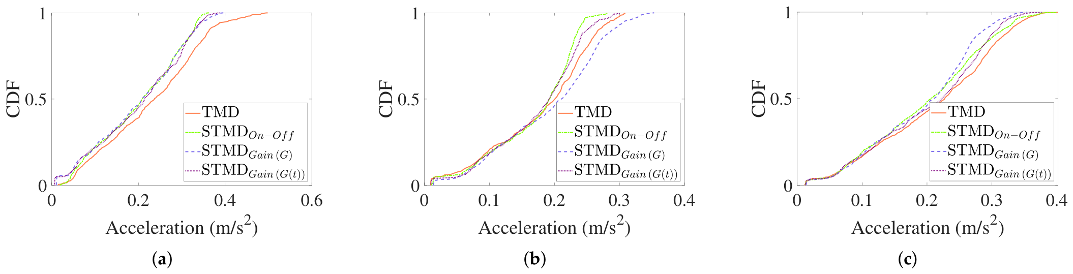
Figure 12 and Figure 13 shows the Cumulative Distribution Function (CDF) of the footbridge acceleration and the 1s-RMS acceleration response for each scenario. It can be seen that all control strategies prevent the acceleration on the structure from exceeding 1.2 m/s2. The STMD performs better control than the TMD in detuning scenarios, which is best appreciated in terms of RMS acceleration in the CDF curve. However, for “Unmodified” scenario (Figure 13b), the STMD with fixed gain G experiences worse behavior than the TMD.
Figure 12.
CDF of the absolute value of the acceleration under walking excitation at the scenario: (a) Detuned below scenario, (b) Unmodified scenario, and (c) Detuned above scenario.
Figure 13.
CDF of the 1s-RMS acceleration for the footbridge under walking excitation at the scenario: (a) Detuned below scenario, (b) Unmodified scenario, and (c) Detuned above scenario.
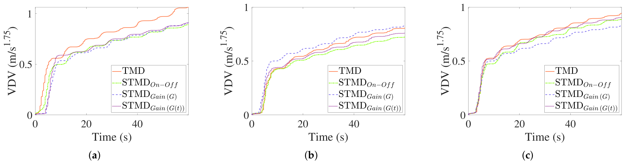
Figure 14 shows that Vibration Dose Value (VDV) of the absolute acceleration. For the “Detuned below” scenario (Figure 14a), the STMD performs a similar response for all phase control laws. For the “Unmodified ” scenario (Figure 14b), the same pattern as in 1s-RMS acceleration is observed. For “Detuned above” (Figure 14c), the best performance is obtained for STMD with fixed gain G, and although the response between phase control laws is not similar, it is better than for TMD.
Figure 14.
VDV of the absolute value of the acceleration under walking excitation at the scenario: (a) Detuned below scenario, (b) Unmodified scenario, and (c) Detuned above scenario.
5. Numerical Study
In this section, simulations of the structure with the STMD subjected to a walking pedestrian are carried out for the three scenarios tested in the experimental implementation.
5.1. Control System Modeling
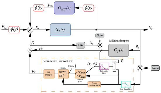
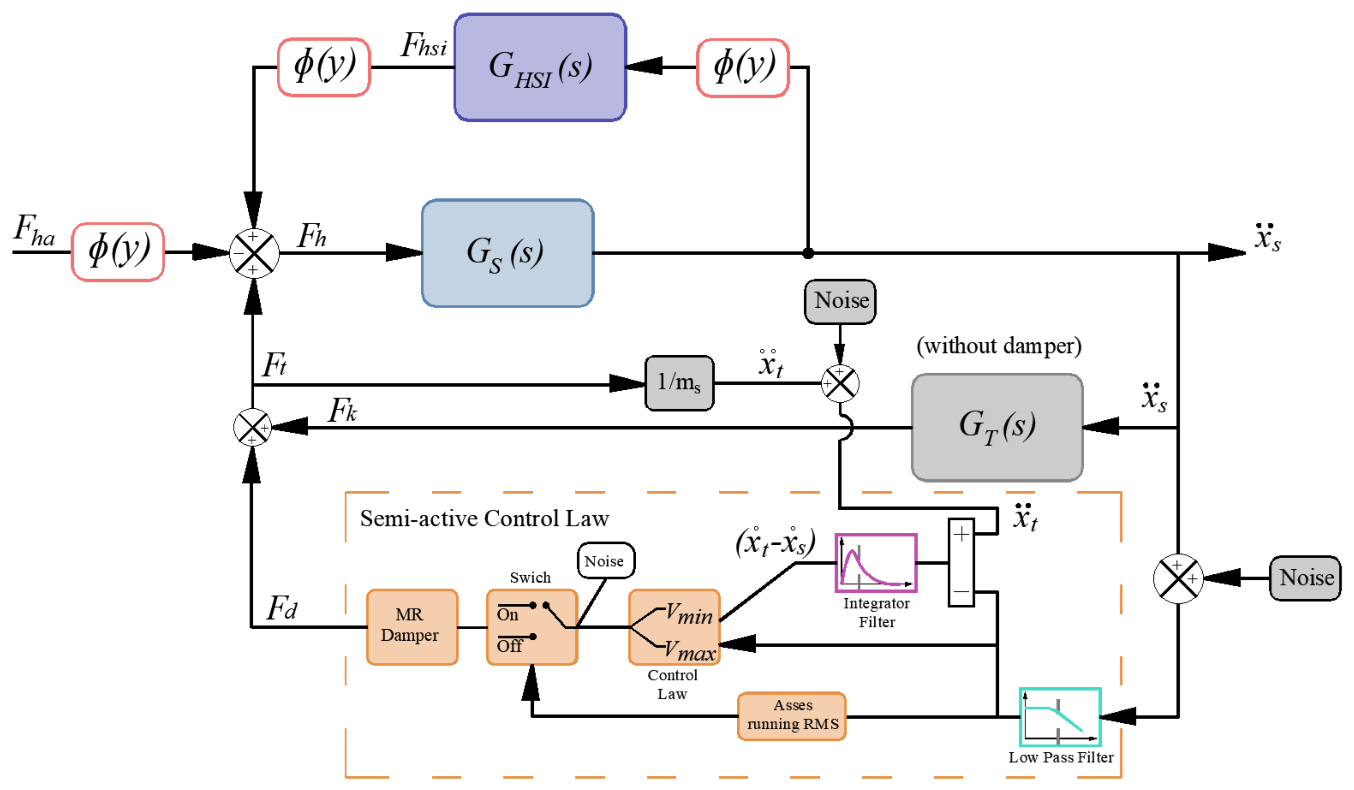
To achieve an accurate and realistic numerical model, variables from the instrumentation have been included, such as the electrical noise measure by accelerometers in structure and STMD, and electrical noise in the control voltage. These noises are defined as noise within a pre-established range: 0.001 m/s2 assumed for the structure accelerometer; 0.01 m/s2 assumed for the accelerometer located in the STMD mass, and 0.02 V assumed for the control voltage. Barrera-Vargas et al. [30] defined these noises and the corresponding filters, including an activate/deactivate rule to avoid the activation of the MR damper under low value of acceleration. Figure 15 illustrates the block diagram of a structure with HSI model and a realistic STMD. The noise in sensors, low-pass filters, integrator filters, and the activate/deactivate rule have been included to represent a realistic scenario.
Figure 15.
Block diagram of the whole control system including HSI, the elements of the STMD and noise on the measurements.
5.2. Dynamic Response Prediction
The desired gait frequency for the three scenarios were, 2.06 Hz, 1.85 Hz, and 2.20 Hz. Even though a metronome was used to walk at each frequency, the pedestrians did not achieve it perfectly. According to Zivanovic et al. [34], an admissible standard deviation of ±0.17 Hz for the gait frequency of pedestrians exists. The gait frequency identified from the Fourier transform of the time-history records for each scenario was as follows: 2.20 Hz, 1.88 Hz, and 2.30 Hz.
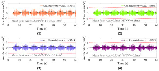
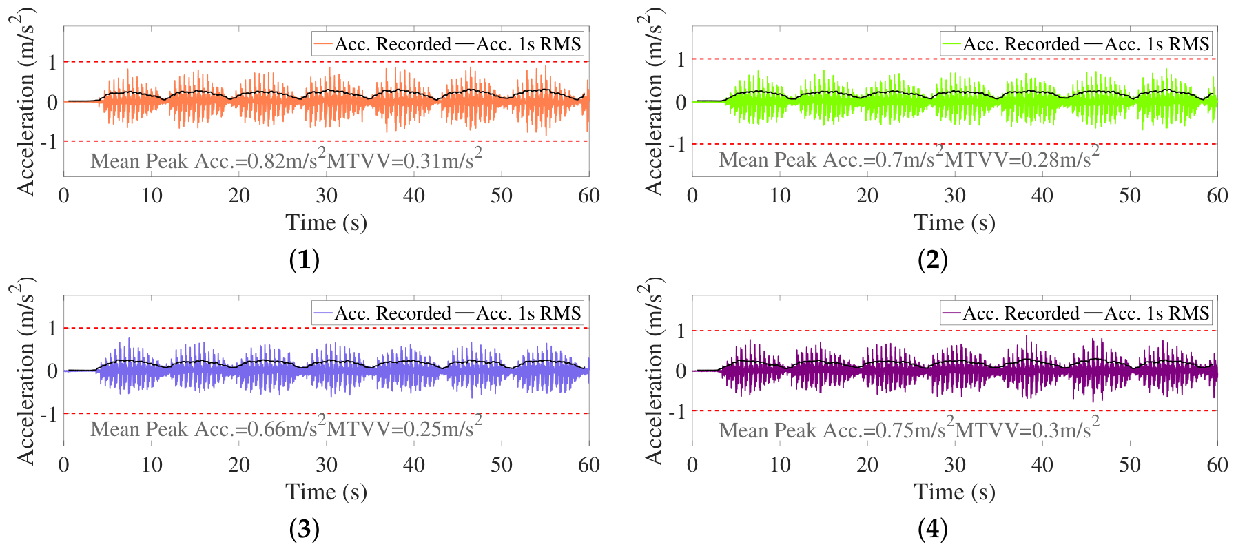
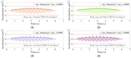
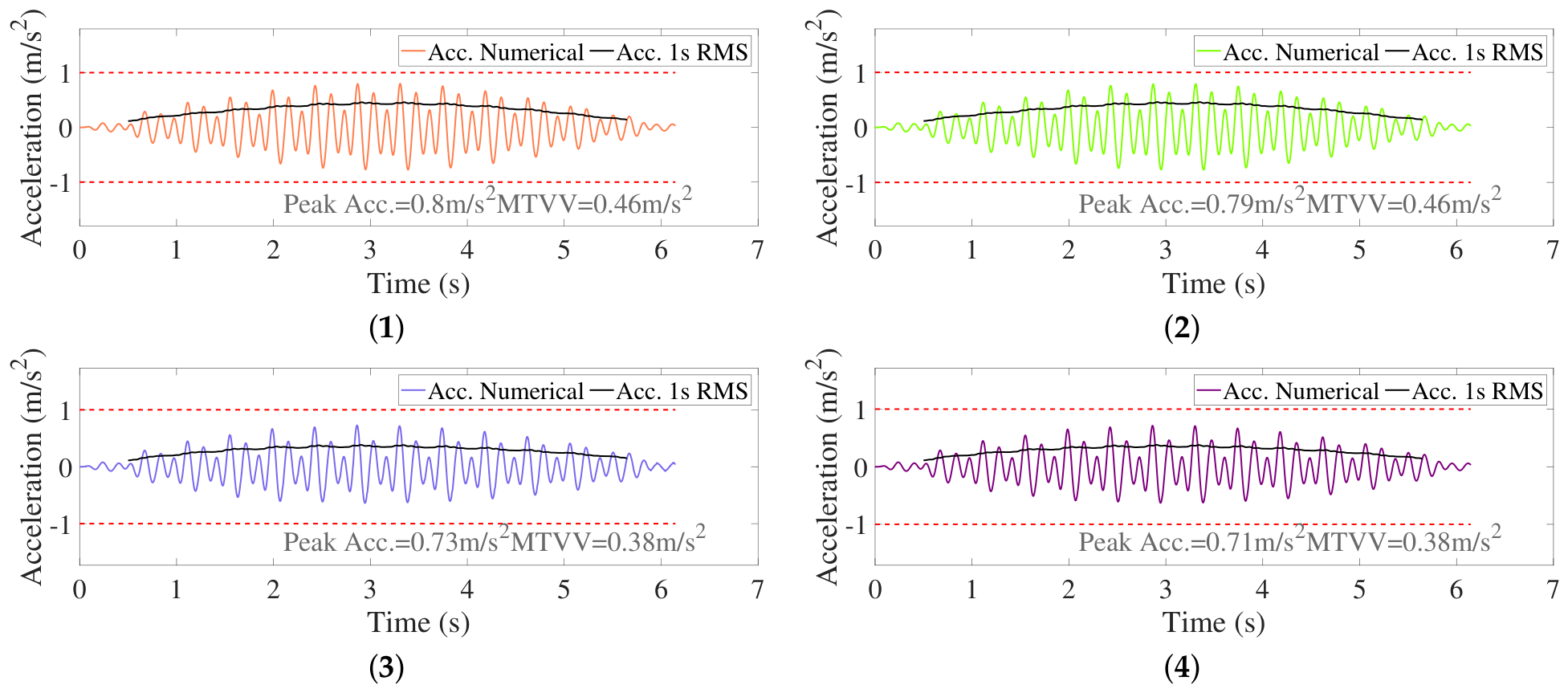
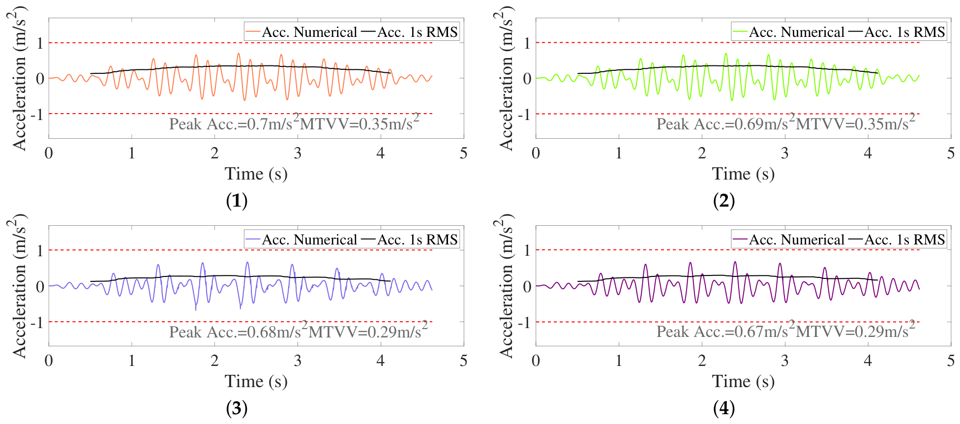
Based on the model presented in Section 5.1 and the gait frequency obtained from the experimental campaign, 12 numerical simulations were performed. Figure 16, Figure 17 and Figure 18 show the calculated response for each control strategy, including the peak acceleration value and MTVV. In Figure 16, the TMD exhibits a peak acceleration of 0.80 m/s2 and an MTVV value of 0.46 m/s2. On the other hand, the STMD, regardless the control strategy, leads to a lower response than the passive controller. Regarding the voltage control strategies, the STMD control strategy with constant gain G and variable gain achieves a better mitigation of the vibrations.
Figure 16.
‘Detuned below’ scenario—Numerical response prediction with a: (1) TMD, (2) STMD On-Off, (3) STMD Gain G, and (4) STMD Gain .
Figure 17.
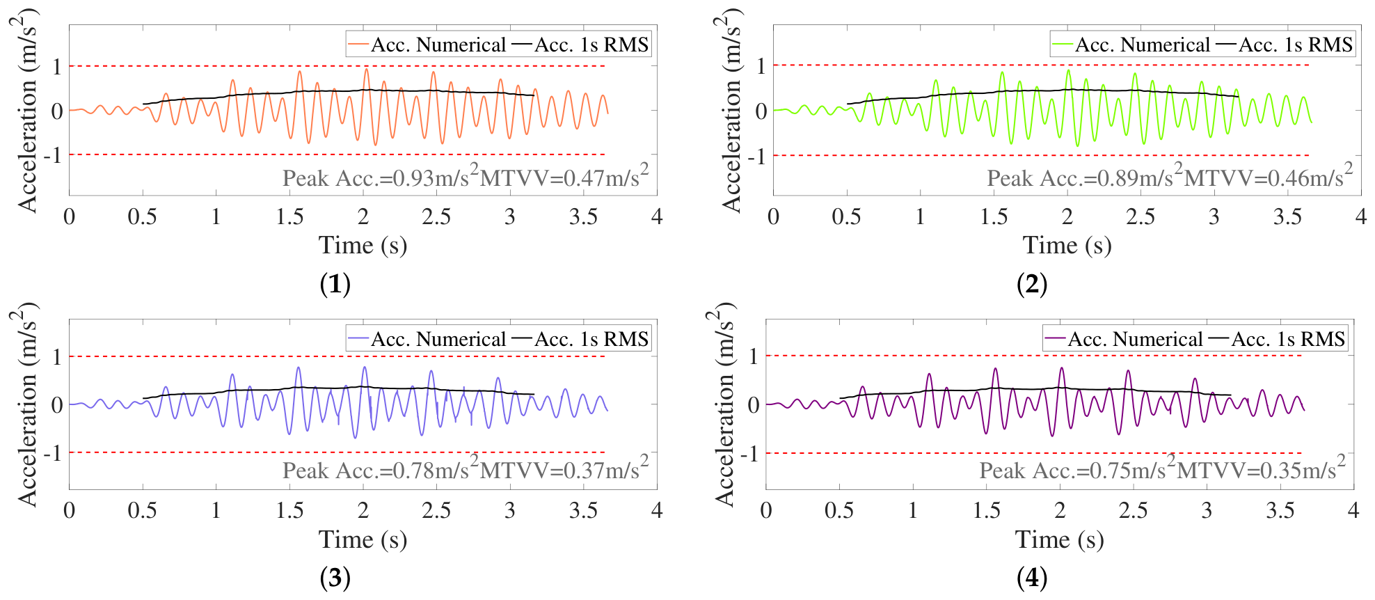
‘Unmodified’ scenario—Numerical response prediction with a: (1) TMD, (2) STMD On-Off, (3) STMD Gain G, and (4) STMD Gain .
Figure 18.
‘Detuned above’ scenario—Numerical response prediction with a: (1) TMD, (2) STMD On-Off, (3) STMD Gain G, and (4) STMD Gain .
In Figure 17, the STMD simulations lead to a lower response amplitude than the TMD one. In the semi-active control strategies, the variable gain G(t) strategy achieves the lowest peak value but a similar MTVV value to the constant gain strategy.
In Figure 18, the TMD develops a similar behavior to the “Unmodified ”scenario, exhibiting an insignificant difference between peak acceleration and MTVV value. Regarding the STMD versions, the On-Off and variable gain G(t) strategies achieve a similar behavior, even in their time-history registers.
6. Discussion
The peak acceleration and MTVV values from the numerical simulations are compared with the experimental results. The values are presented in Table 2 and Table 3, respectively.
Table 2.
Comparison of Peak Acceleration (m/s2) for the three scenarios.
Table 3.
Comparison of MTVV(m/s2) for the three scenarios.
The Relative Percentage Error (RPE) is evaluated between numerical results (NUM) and experimental results (EXP), taking EXP as the reference value. Negative values of RPE indicate values of NUM lower than EXP. While positive values of RPE indicate values of NUM greater than EXP.
The numerical predictions generally yielded to lower peak acceleration values than the experimental measurements. The numerical prediction provides a good approximation of experimental measurement, with RPE values below 20%, except for the passive control in the detuned below scenario.
The numerical predictions of the MTVV (m/s2) also achieve satisfactory estimation. Ten out of twelve tests led to an RPE below 20%. In addition, the voltage strategy with variable gain obtained one of the best predictions, reproducing similar values to the experimental measurements.
7. Conclusions
This paper presents the implementation of a STMD for lightweight footbridges susceptible to human-induced vibrations, with the aim of validating a numerical model of a STMD. The STMD is composed of an inertial mass, four springs, and two sponge MR dampers, whose behavior was experimentally identified through a hyperbolic tangential model.
The evaluation of the semi-active device has been carried out considering two conditions, a tuned and a detuned behavior between the controller and the footbridge. The control strategy used to govern the response of the MR dampers in the STMD was a phase control law combined with three voltage controllers, namely: (i) an On-Off control, (ii) a continuous-gain control, and (iii) a variable-gain control. In the practical implementation of the phase control, two accelerometers were used to measure the acceleration response of the main structure and the inertial mass of the STMD. To avoid false activation of the STMD, a switching rule was implemented. This rule is based on the running RMS value computed from the structural acceleration. The high-frequency content present in the acceleration signal was removed using a low-pass filter, while the acceleration was transformed into velocity using an integrator filter.
The tests demonstrated that the numerical model of the STMD, considering realistic conditions and a sponge MR damper through a hyperbolic tangential model, is effective in reproducing realistic behaviors. With respect to three voltage controllers, the continuous-gain and variable-gain control laws provided the best performance for the STMD. In terms of acceleration response, the best behavior was achieved in the “Unmodified” scenario, since the structure and the control devices were tuned to the same frequency. In contrast, the worst behavior achieved by the STMD was observed in the “Detuned below” case. At a lower structural resonance frequency, the STMD was unable to adjust its frequency because the MR dampers can only restrict the motion of the inertial mass. In the “Detuned above” case, the MR dampers demonstrated their capability to adjust the STMD frequency to match the footbridge frequency.
Future work will assess the performance of the STMD under different control strategies considering a crowd of walking pedestrians while accounting for human–structure interaction phenomena. In addition, further numerical investigations should be carried out to incorporate non-linear effects, such as friction in mechanical components and the heating of the MR damper, even under passive operating conditions.
Author Contributions
Conceptualization, C.A.B.-V. and I.M.D.; methodology, C.A.B.-V., C.G.-C. and I.M.D.; software, C.A.B.-V. and C.G.-C.; validation, C.A.B.-V. and C.G.-C.; formal analysis, C.A.B.-V., C.G.-C., and I.M.D.; investigation, C.A.B.-V. and C.G.-C.; resources, I.M.D.; data curation, C.A.B.-V. and C.G.-C.; writing—original draft preparation, C.A.B.-V. and C.G.-C.; writing—review and editing, I.M.D.; visualization, C.A.B.-V. and C.G.-C.; supervision, I.M.D.; project administration, I.M.D.; funding acquisition, I.M.D. All authors have read and agreed to the published version of the manuscript.
Funding
This research was funded by the projects: Shanghai Municipal Science and Technology Commission through the Shanghai Partner Research Program under the project number 25HB2707900. Research project PID2021-127627OB-I00 (Transport Infrastructures subjected to dynamic loading: assessment techniques for the sustainability, intelligent maintenance and comfort) funded by Ministerio de Ciencia e Innovacion, Agencia Estatal de Investigacion and 10.13039/501100011033 FEDER, European Union.
Institutional Review Board Statement
The study was conducted according to the guidelines of the Declaration of Helsinki and following the normative of the Ethics Committee of Universidad Politécnica de Madrid.
Informed Consent Statement
Informed consent was obtained from all subjects involved in the study.
Data Availability Statement
The data presented in this study are available on request from the corresponding author.
Acknowledgments
Christian Gallegos-Calderón expresses his gratitude to SENESCYT-Ecuador for the financial support.
Conflicts of Interest
Author Christian A. Barrera-Vargas was employed by the company Research Unit on Structural Dynamics and Control (UIDCE), Dynamic Engineering SAS. The remaining authors declare that the research was conducted in the absence of any commercial or financial relationships that could be construed as a potential conflict of interest.
References
- Boniface, V.; Bui, V.; Bressolette, P.; Charles, P.; Cespedes, X. Footbridges: Assessment of Vibrational Behaviour of Footbridges Under Pedestrian Loading; Technical Report; Service d’Études Techniques des Routes et Autoroutes: Paris, France, 2006. [CrossRef] [Scilit]
- Heinemeyer, C.; Butz, C.; Keil, A.; Schlaich, M.; Goldack, A. Design of Lightweight Footbridges for Human Induced Vibrations; European Commission: Luxembourg, 2009. [Google Scholar] [CrossRef] [PubMed]
- ISO 10137; Bases for Design of Structures—Serviceability of Buildings and Walkways Against Vibrations. International Organization for Standardization: Geneva, Switzerland, 2012.
- prEN 1991-2:2020; Working Document: Actions on Structures—Part 2: Traffic Loads on Bridges. European Committee for Standardization: Brussels, Belgium, 2020.
- Jiménez-Alonso, J.F.; Sáez, A. A direct pedestrian-structure interaction model to characterize the human induced vibrations on slender footbridges. Inf. Constr. 2014, 66, m007. [Google Scholar] [CrossRef] [Scilit]
- Zhang, S.; Wu, B.; Tang, Y.; Zhang, H.; Xu, Z.; Li, G.; Lu, S. A Review on Comfort of Pedestrian Bridges Under Human-Induced Vibrations and Tuned Mass Damper Control Technologies. Materials 2025, 18, 3903. [Google Scholar] [CrossRef] [Scilit] [PubMed]
- Ahmadi, E.; Caprani, C.; Živanović, S.; Heidarpour, A. Assessment of human-structure interaction on a lively lightweight GFRP footbridge. Eng. Struct. 2019, 199, 109687. [Google Scholar] [CrossRef] [Scilit]
- Díaz, I.; Gallegos, C.; Ramírez Senent, J.; Renedo, C. Interaction Phenomena to Be Accounted for Human-Induced Vibration Control of Lightweight Structures. Front. Built Environ. 2021, 7, 658529. [Google Scholar] [CrossRef] [Scilit]
- Fouli, M.; Camara, A. Human–Structure Interaction Effects on Lightweight Footbridges with Tuned Mass Dampers. Structures 2024, 62, 106263. [Google Scholar] [CrossRef] [Scilit]
- Gallegos-Calderón, C.; Naranjo-Pérez, J.; García-Palacios, J.H.; Díaz, I.M. Design and Performance of a Tuned Vibration Absorber for a Full-Scale Lightweight FRP Pedestrian Structure. J. Compos. Constr. 2022, 26, 04022077. [Google Scholar] [CrossRef] [Scilit]
- Soria, J.; Jiménez-Alonso, J.; Renedo, C.; Gallegos-Calderón, C. Exploring Semi-Active TMD Performance on Lively Footbridges Considering Human–Structure Interaction in Vertical Direction. Int. J. Struct. Stab. Dyn. 2024, 25, 2540010. [Google Scholar] [CrossRef] [Scilit]
- Weber, F.; Maślanka, M. Frequency and Damping Adaptation of a TMD with Controlled MR Damper. Smart Mater. Struct. 2012, 21, 055011. [Google Scholar] [CrossRef] [Scilit]
- Weber, F. Semi-Active Vibration Absorber Based on Real-Time Controlled MR Damper. Mech. Syst. Signal Process. 2014, 46, 272–288. [Google Scholar] [CrossRef] [Scilit]
- Yang, Y.; Liu, C.; Chen, L.; Zhang, X. Phase Deviation of Semi-Active Suspension Control and Its Compensation with Inertial Suspension. Acta Mech. Sin. 2024, 40, 523367. [Google Scholar] [CrossRef] [Scilit]
- Ferreira, F.; Moutinho, C.; Cunha, A.; Caetano, E. Use of Semi-Active Tuned Mass Dampers to Control Footbridges Subjected to Synchronous Lateral Excitation. J. Sound Vib. 2019, 446, 176–194. [Google Scholar] [CrossRef] [Scilit]
- Wang, L.; Nagarajaiah, S.; Shi, W.; Zhou, Y. Semi-Active Control of Walking-Induced Vibrations in Bridges Using Adaptive Tuned Mass Damper Considering Human-Structure-Interaction. Eng. Struct. 2021, 244, 112743. [Google Scholar] [CrossRef] [Scilit]
- Wang, L.; Zhou, Y.; Shi, W. Random Crowd-Induced Vibration in Footbridge and Adaptive Control Using Semi-Active TMD Including Crowd-Structure Interaction. Eng. Struct. 2024, 306, 117839. [Google Scholar] [CrossRef] [Scilit]
- Aguirre, N. Magnetorheological Dampers: Modeling and Control Design for Civil Engineering Structures. Ph.D. Thesis, Universitat Politècnica de Catalunya, Barcelona, Spain, 2011. [Google Scholar]
- Koo, J.; Ahmadian, M.; Setareh, M.; Murray, T. In Search of Suitable Control Methods for Semi-Active Tuned Vibration Absorbers. J. Vib. Control. 2004, 10, 163–174. [Google Scholar] [CrossRef]
- Moutinho, C. Testing a Simple Control Law to Reduce Broadband Frequency Harmonic Vibrations Using Semi-Active Tuned Mass Dampers. Smart Mater. Struct. 2015, 24, 055007. [Google Scholar] [CrossRef] [Scilit]
- Hanagan, L. Active Control of Floor Vibrations. Ph.D. Thesis, Virginia Polytechnic Institute and State University, Blacksburg, VA, USA, 1994. [Google Scholar]
- Nyawako, D.; Reynolds, P. Response-Dependent Velocity Feedback Control for Mitigation of Human-Induced Floor Vibrations. Smart Mater. Struct. 2009, 18, 075002. [Google Scholar] [CrossRef] [Scilit]
- LORD Corporation. Data Sheet—MR Dampers; Technical Report; LORD Corporation: Cary, NC, USA, 2020. [Google Scholar]
- Renedo, C.; Díaz, I.; Russell, J.; Živanovic, S. Performance of Inertial Mass Controllers for Ultra-Lightweight Footbridges: A Case Study. In Proceedings of the XI International Conference on Structural Dynamics (EURODYN), Athens, Greece, 23–26 November 2020; Volume 1, pp. 1741–1746. [Google Scholar] [CrossRef] [Scilit]
- Gallegos-Calderón, C.; Naranjo-Pérez, J.; Pulido, M.; Díaz, I. Design, Construction and Structural Response of a Lightweight FRP Footbridge. In Proceedings of the IABSE Congress 2021—Structural Engineering for Future Societal Needs, Ghent, Belgium, 22–24 September 2021. [Google Scholar]
- Gallegos-Calderón, C.; Naranjo-Pérez, J.; Díaz, I.; Goicolea, J. Identification of a Human-Structure Interaction Model on an Ultra-Lightweight FRP Footbridge. Appl. Sci. 2021, 11, 6654. [Google Scholar] [CrossRef] [Scilit]
- PCB Piezotronics, Inc. Data Sheet—Model 393B12 ICP Seismic Accelerometer; Technical Report; PCB Piezotronics, Inc.: Depew, NY, USA; Available online: https://www.pcb.com/products?m=393b12 (accessed on 19 January 2024).
- Kwok, N.; Ha, Q.; Nguyen, T.; Li, J.; Samali, B. A Novel Hysteretic Model for Magnetorheological Fluid Dampers and Parameter Identification Using Particle Swarm Optimization. Sens. Actuators A Phys. 2006, 132, 441–451. [Google Scholar] [CrossRef] [Scilit]
- MathWorks. MATLAB—Getting Started Guide; MathWorks: Natick, MA, USA, 2025. [Google Scholar]
- Barrera-Vargas, C.A.; Naranjo-Pérez, J.; Díaz, I.M.; García-Palacios, J.H. Design of a Semiactive TMD for Lightweight Pedestrian Structures Considering Human–Structure–Actuator Interaction. Actuators 2022, 11, 101. [Google Scholar] [CrossRef] [Scilit]
- Soong, T.; Dargush, G. Passive Energy Dissipation Systems in Structural Engineering; John Wiley & Sons: Chichester, UK, 1997. [Google Scholar]
- Karnopp, D. Active and Semi-Active Vibration Isolation. J. Mech. Des. 1995, 117, 177–185. [Google Scholar] [CrossRef] [Scilit]
- Feldmann, M.; Heinemeyer, C.; Lukic, M.; Caetano, E.; Cunha, A.; Goldack, A.; Keil, A.; Schlaich, M.; Hicks, S.; Smith, A.; et al. Human-Induced Vibration of Steel Structures (HIVOSS), EUR 24183 EN; Technical Report; Office for Official Publications of the European Communities: Luxembourg, 2010. [Google Scholar] [CrossRef] [PubMed]
- Živanović, S.; Pavic, A.; Reynolds, P. Vibration serviceability of footbridges under human-induced excitation: A literature review. J. Sound Vib. 2005, 279, 1–74. [Google Scholar] [CrossRef] [Scilit]

Disclaimer/Publisher’s Note: The statements, opinions and data contained in all publications are solely those of the individual author(s) and contributor(s) and not of MDPI and/or the editor(s). MDPI and/or the editor(s) disclaim responsibility for any injury to people or property resulting from any ideas, methods, instructions or products referred to in the content. |
© 2026 by the authors. Licensee MDPI, Basel, Switzerland. This article is an open access article distributed under the terms and conditions of the Creative Commons Attribution (CC BY) license.