


Abstract
To address the limited grasping stroke (GS) of piezoelectric-actuated microgrippers, this paper proposes a novel symmetric microgripper configuration integrating reversed Scott Russell (S–R) mechanisms and differential lever amplification mechanisms (DLAMs). Four reversed S–R mechanisms are arranged in parallel and connected via a central linkage, which is actuated by a piezoelectric stack actuator (PSA). The tension–compression deformation of the parallel S–R units generates two pairs of displacements with equal magnitudes and opposite directions, which are further transmitted to the DLAM to amplify the GS. A semi-analytical mechanical model of the microgripper is established, incorporating a simplified PSA model to describe the mechanical behavior of the actuator. Based on the analytical model, the displacement amplification ratio (DAR) and first-order natural frequency (FNF) are selected as dual optimization objectives to optimize the structural geometric parameters. The static and dynamic performances of the proposed microgripper are preliminarily validated via finite element simulations and experiments. Experimental results show that the microgripper achieves a GS of 857 μm, a bilateral DAR of 68, and an FNF of 265 Hz. Although the modeling error is relatively large, the established model can still provide guidance for the integrated design of the microgripper. Finally, grasping tests further demonstrate that the developed microgripper can be applied to micromanipulation and microassembly tasks.
1. Introduction
As a dominant class of end-effectors for micromanipulation robots, microgrippers actuated by piezoelectric stack actuators (PSAs) feature compact size, high displacement resolution, rapid response, and reliable operational stability for grasping, manipulation, and release of target objects [1,2,3]. However, the output displacement of PSAs is typically limited to tens of micrometers, which cannot satisfy the growing demand for grasping stroke (GS) at the hundreds-of-micrometer or even millimeter scale [4,5,6].
To overcome this limitation, compliant displacement amplification mechanisms (CDAMs), such as lever-type [7,8], bridge-type [9], and Scott Russell mechanisms [10], are developed to amplify the output displacement of PSAs [11,12]. In recent years, differential lever amplification mechanisms (DLAMs), which feature a large displacement amplification ratio (DAR), have attracted increasing attention. Li and Chen designed and optimized a two-stage DLAM with a DAR up to 48 [13,14]. Fan et al. developed a DLAM that achieves an amplification ratio of 6.68 and output displacement of 300 μm [15]. Hou et al. combined DLAMs with bridge-type mechanisms to develop a lever-bridge differential amplifier, which realized a DAR of 7.3 and improved the structural symmetry [16]. Du et al. proposed a 3-DOF translational compliant precision positioning stage based on DLAMs, achieving a single-axis output displacement of 391.42 μm and a DAR of 13.05 [17]. Wu and Chen proposed a differential amplifier/reducer and realized a high-magnitude displacement amplification/reduction ratio of 98.1/100 [18,19].
In addition, DLAMs have been adopted in the design of piezoelectric-actuated microgrippers. For instance, Sun et al. integrated a DLAM with a Scott Russell (S-R) mechanism to develop a symmetric microgripper. Experimental results demonstrate that the gripper achieves a large GS of 634.2 μm [20]. Liu et al. designed a microgripper based on symmetric DLAMs, achieving a total DAR of 36.3 and a GS of 344.95 μm [21]. The above studies reveal that DLAMs can enhance the DAR and output displacement. However, DLAMs constructed with conventional lever-type mechanisms inevitably lead to increased structural size, reduced output force, and deteriorated dynamic characteristics [22]. Therefore, in terms of mechanism design, more research is needed on integrating DLAMs with other amplification mechanisms to take advantage of their high displacement amplification capability while maintaining a balance among other performance metrics.
In this paper, a novel symmetric piezoelectric-actuated microgripper based on DLAMs and reversed S-R mechanisms [23] was proposed. Compared with DLAMs based on lever-type mechanisms, the gripper featured a compact structure and improved static and dynamic performance. Moreover, a semi-analytical method was adopted to model the mechanical performance of the gripper. The PSA was simplified as a beam element and integrated into the model, considering the stiffness connection between the PSA and the mechanism to simplify the design process. The remainder of this paper is organized as follows. Section 2 introduces the mechanical structure of the proposed microgripper. Section 3 formulates the mechanical model using the semi-analytical method. Section 4 presents the multi-objective optimization of the microgripper and identifies the geometric parameters to balance its static and dynamic performance. Finite element analysis and experimental validation are performed in Section 5 and Section 6, and the results are discussed in Section 7. Finally, conclusions are drawn in Section 8.
2. Mechanism Design
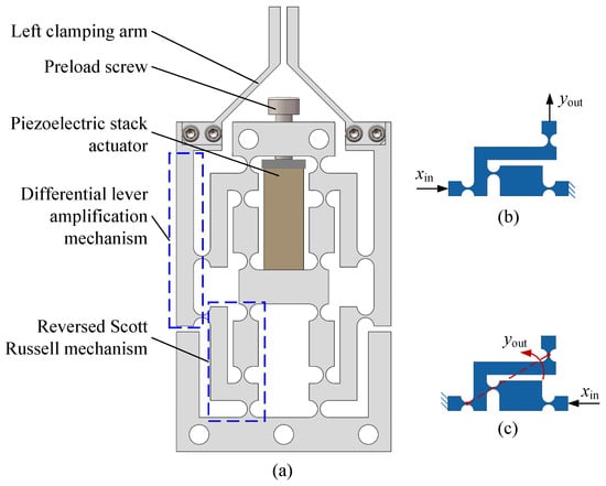
The proposed microgripper based on DLAMs and reversed S-R mechanisms is shown in Figure 1a. Four reversed S-R mechanisms are arranged in a mirror-symmetric parallel configuration, which are analogous to the bridge arms of the bridge-type mechanism. The middle connecting rod divides the mechanism into upper and lower parts and acts as the displacement input terminal. When actuated by the PSA, the upper and lower parts undergo tension and compression deformation and both produce amplified displacements. As illustrated in Figure 1a, the output displacements of any two adjacent reversed S-R mechanisms are equal in magnitude and opposite in direction. On the left and right sides, the two output displacement terminals are connected to the two input ports of the DLAMs, which serve as rotational clamping arms. Finally, with the amplification effect of the S-R mechanism and DLAMs, the performance of the microgripper is improved.
Figure 1.
Mechanical configuration of the designed piezoelectric-actuated microgripper: (a) overall microgripper; (b) Scott Russell mechanism; (c) reversed Scott Russell mechanism.
It is worth noting that the reversed S-R mechanism (Figure 1c) is a variant of the S-R mechanisms (Figure 1b). A key feature of the S-R mechanism is its capability to generate translational output displacement perpendicular to the input displacement. Since the DLAM delivers clamping motion via rotational movement, the reversed S-R mechanism adopts a similar structural layout to the S-R mechanism but differs in its operating principle. Furthermore, it does not follow the dimensional constraints required for the S-R mechanisms. Instead, the reversed S-R mechanism realizes fixed-point rotation, and its design objective is to achieve a high DAR. As shown in Figure 1, the microgripper features a compact and strictly symmetric structure, which is beneficial to improving its overall static and dynamic performance.
3. Theoretical Modeling
Accurate theoretical models lay the foundation for performance analysis and optimization of compliant mechanisms. The main theoretical modeling approaches for compliant mechanisms include the pseudo-rigid-body model (PRBM) [24], compliance matrix method [25,26], semi-analytical method [27,28,29], etc. Based on the structural configuration of the proposed microgripper, the semi-analytical method is adopted owing to its high accuracy and simplicity. Using the established model, key performance metrics of the microgripper, including the GS, DAR and first-order natural frequency (FNF), can be derived.
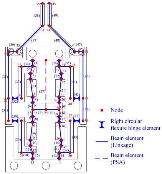
The semi-analytical method follows the basic framework of the finite element method. First, the microgripper was discretized into 49 nodes and 45 elements. The element and node numbering as well as their connectivity are illustrated in Figure 2. Two types of elements are defined, i.e., right circular flexure hinge elements and beam elements, which are used to model flexure hinges and linkages, respectively. It is worth noting that the deformation of linkages is considered in the semi-analytical method, whereas linkages are treated as rigid bodies in the RPBM. Thus, the semi-analytical method achieves higher modeling accuracy compared with the RPBM.
Figure 2.
Node and element discretization of the microgripper.
The fundamental formulas for the finite element method are adopted in the modeling and will not be repeated here. In this section, the force–displacement relationship of right circular flexure hinge elements and the equivalent beam element of the PSA are detailed.
3.1. Right Circular Flexure Hinge Element
The right circular flexure hinges act as revolute hinges in the microgripper, and the element stiffness matrix can be expressed as
where , and can be derived from the compliance matrix of right circular flexure hinges, and the derivation process can be found in Refs. [27,30].
where
where and r are the out-of-plane height and radius of the right circular flexure hinge, respectively, and , is its the minimum thickness.
3.2. Equivalent Beam Element of PSA
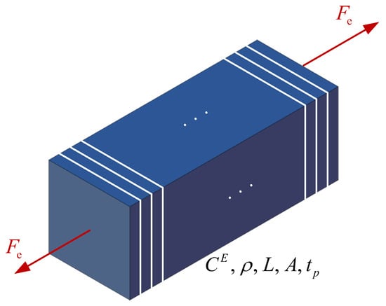
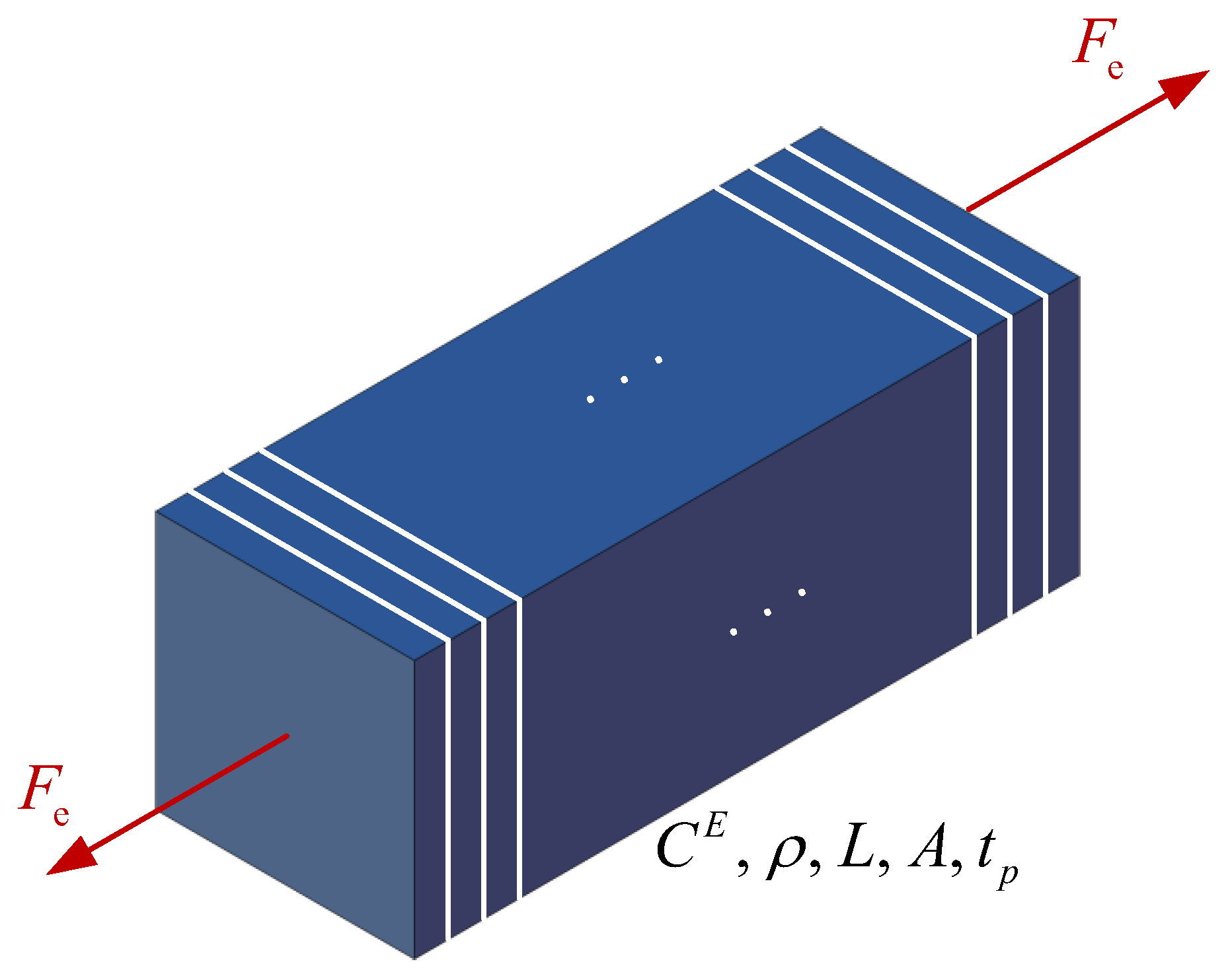
In the design process of compliant mechanisms, the input stiffness of the mechanism is determined first, and then an adoptable PSA is selected. However, stiffness matching affects the output displacement and induces displacement loss of the physical mechanism. Therefore, Integrating the force–displacement relationship of the PSA into the mechanical model of the microgripper can improve the design efficiency. Zhang and Lu proposed a homogeneous mechanical solid with a pair of equivalent forces applied at its two ends to model the electromechanical coupled-field effect of the PSA [31]. Considering the symmetry of the microgripper, the PSA is subjected to forces only along the longitudinal direction. Therefore, this equivalent model can be further converted into a beam element and embedded into the finite element model of the microgripper. The equivalent beam element of the PSA is shown in Figure 3. There are hundreds of piezo layers connected mechanically in series and electrically in parallel, and the piezoelectric constitutive equations of piezoelectricity can be expressed as:
where and , are strain tensor and stress tensor, respectively, and is the elastic compliance constant. , and and are applied voltage and the thickness of piezo layer, respectively. Since the PSA is designed for operations in the polarization direction, the strain-stress relation along longitudinal direction is written as,
where
Figure 3.
Equivalent beam element of the PSA [31].
In Equation (7), can be taken as the stress induced by the applied voltage. Therefore, the equivalent force can be obtained as
As shown in Figure 3, , , L, and A are equivalent Young’s module, mass density, the longitudinal length and cross-sectional area of the PSA. When a actuating voltage is applied, the actuating force is obtained by Equation (10), and the element stiffness and mass can be determined by the specified parameters.
3.3. Semi-Analytical Modeling of the Microgripper
As shown in Figure 2, all linkages, right circular flexure hinges, and the PSA of the microgripper are discretized into 49 elements, and then the element mass matrix and element stiffness matrix are transformed into the global coordinate system to assemble the system mass matrix and system stiffness matrix . Based on vibration theory, the vibration differential equation can be expressed as
where and denote the generalized displacement vector and generalized force vector of the microgripper, respectively.
It is observed that nodes 1 and 13 are fixed constraint nodes, and node 25 serves as the actuating force or displacement terminal of the PSA. In addition, nodes 28 and 29, 38 and 39 are displacement input nodes of the left and right differential levers, while nodes 35 and 45 are the displacement output nodes of the microgripper. Combined with displacement and force boundary conditions, the nodal displacements and nodal forces can be obtained by solving the static equilibrium equations of Equation (11). Therefore, the unilateral DAR of the microgripper is expressed as
In addition, by solving the characteristic equation
the corresponding vibration frequencies can be obtained.
4. Multi-Objective Optimization
It is evident that a trade-off exists between the DAR and the FNF in the design of the microgripper. Based on the analytical model developed in Section 3, a multi-objective optimization algorithm can be adopted to generate the Pareto front for DAR and FNF, from which the optimal dimensional parameters of the microgripper can be determined.
4.1. Optimization Variables
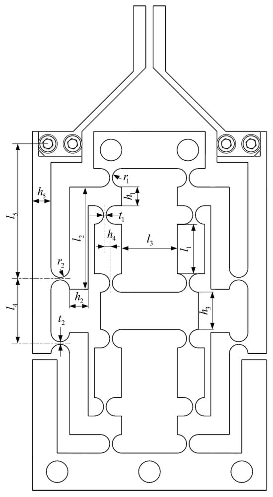
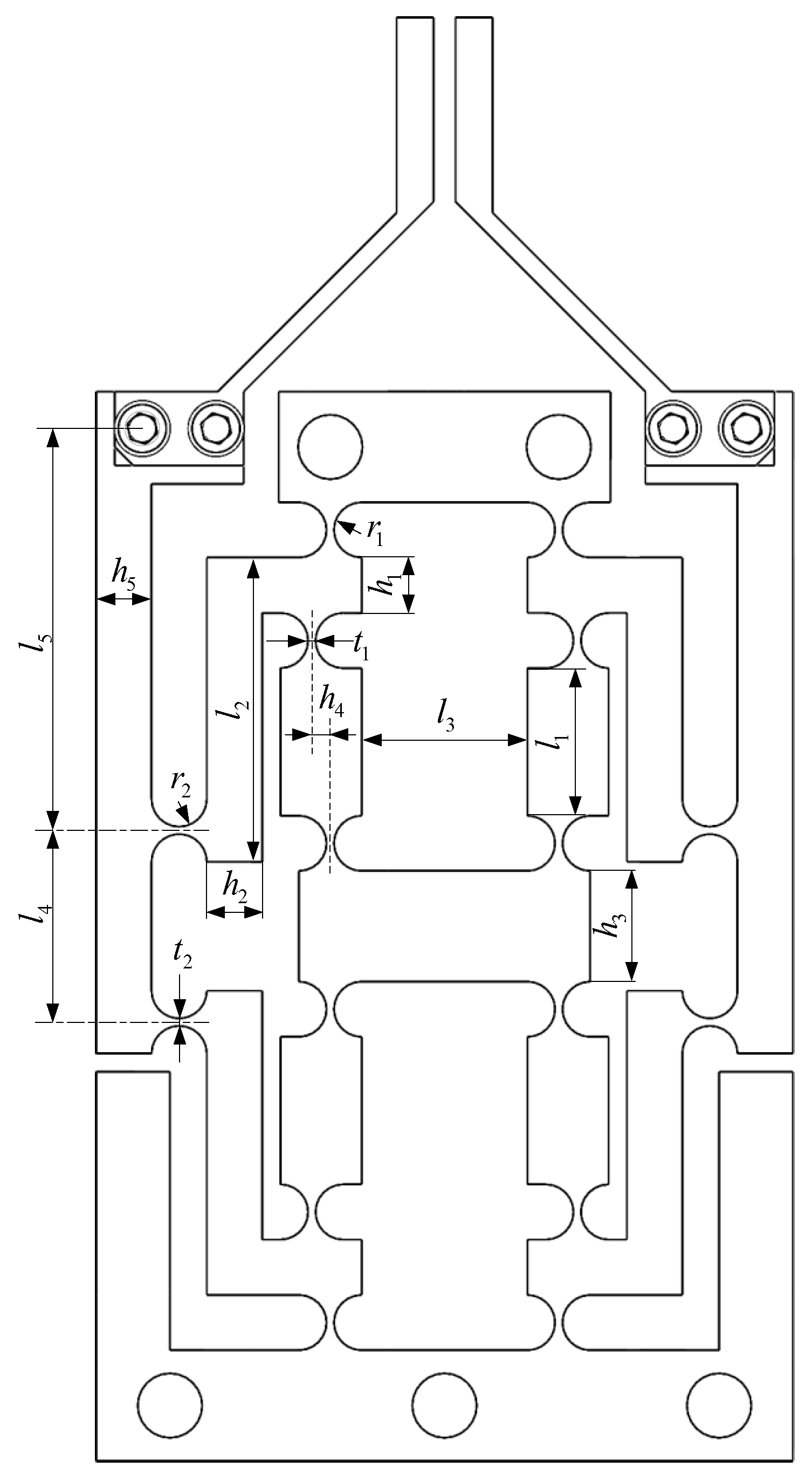
As mentioned above, the DAR and FNF are selected as two optimization objectives. To simplify the optimization model and improve optimization efficiency, the design variables, i.e., geometric dimensions, are first analyzed to determine the optimization variables. The design dimensions of the microgripper are illustrated in Figure 4, and all the other dimensions can be derived from these parameters. The one-factor-at-a-time method is employed to examine parameter sensitivity relative to the design objectives, and then optimization variables are selected accordingly.
Figure 4.
Design dimensions of the microgripper.
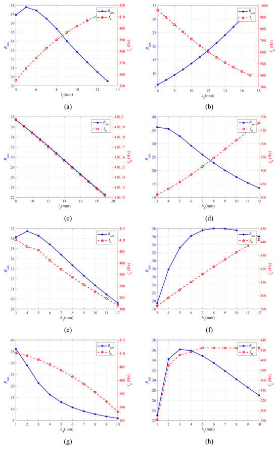
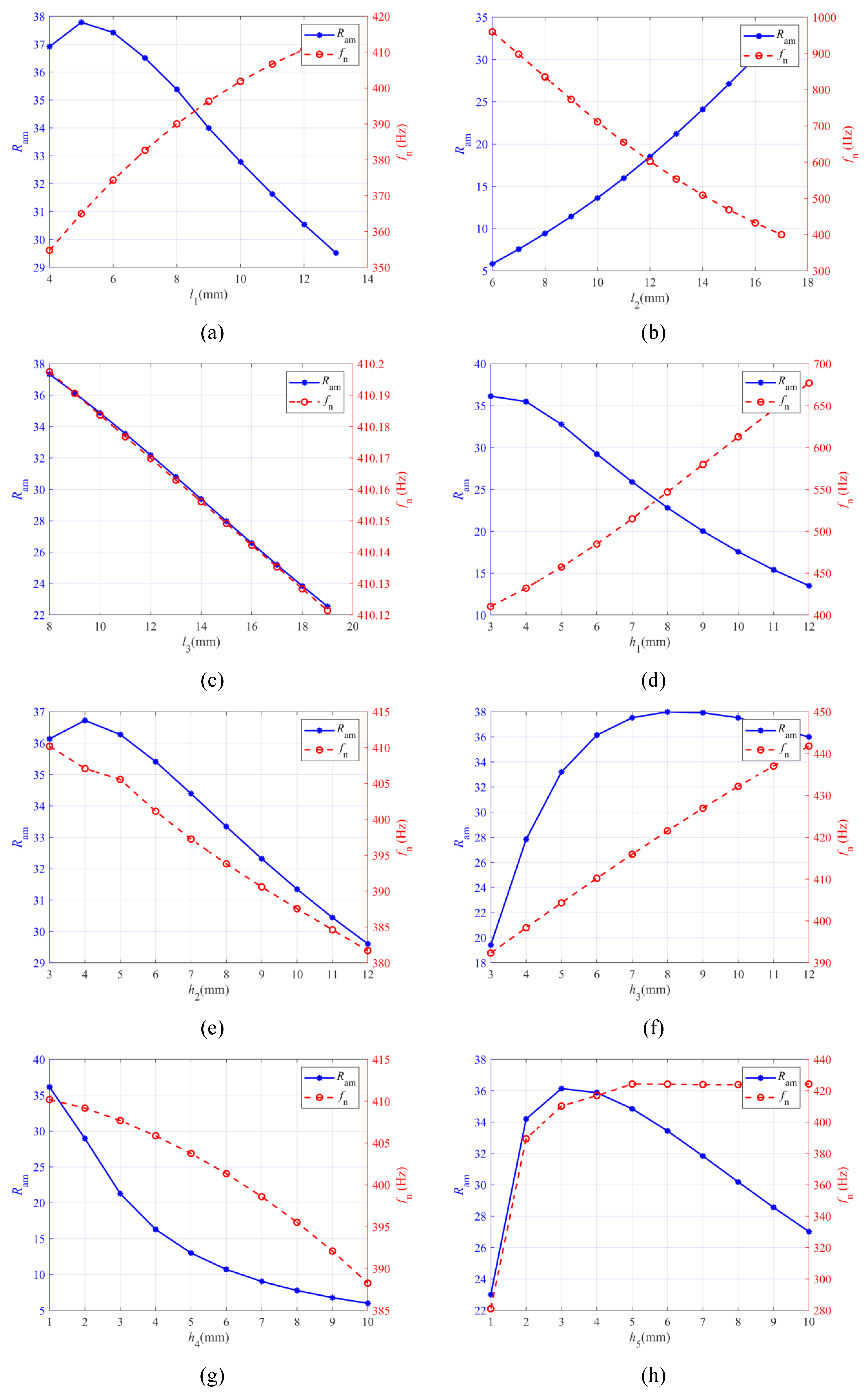
The effects of , , , , , , , and on the unilateral DAR and FNF of the microgripper are shown in Figure 5. From Figure 5a,d, it is seen that decreases rapidly and rises sharply with the increase of and . By contrast, the variation trends in Figure 5b are entirely different. Figure 5c,e,g reveal that the effects of , and on the and are reasonably consistent, and they exhibit a negative correlation. Figure 5f,h suggest that both the and increase when and increase, but the changing trends of the two parameters are different.
Figure 5.
Effects of design variables on the DAR and FNF of the microgripper: (a) ; (b) ; (c) ; (d) ; (e) ; (f) ; (g) ; (h) .
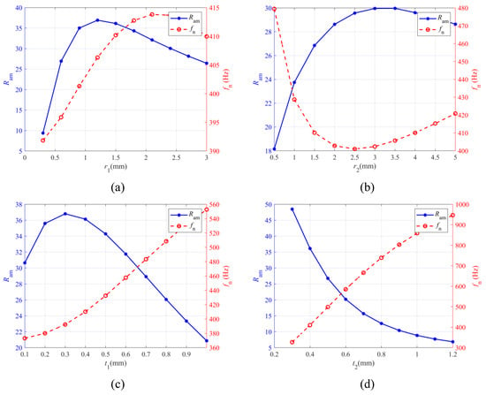
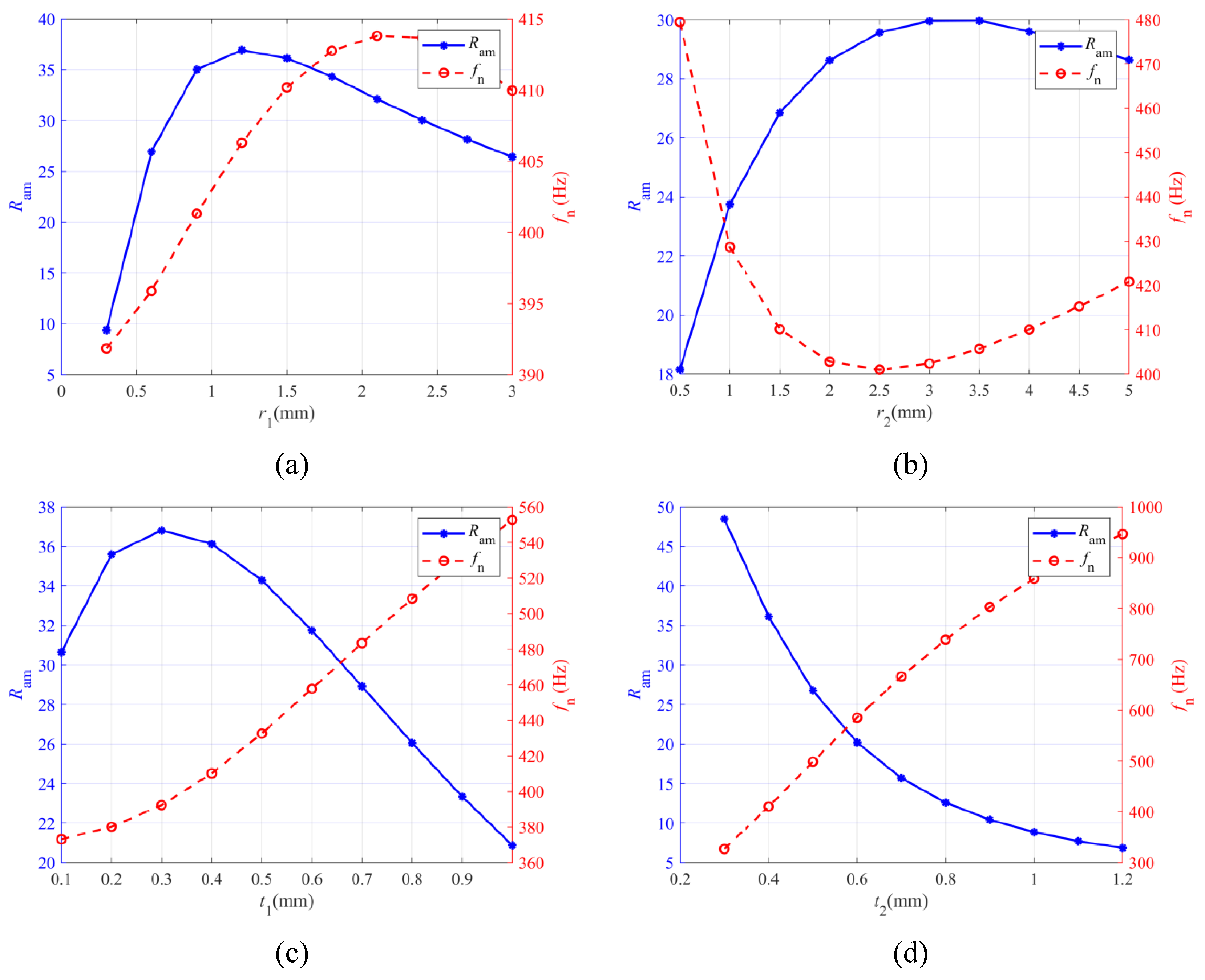
Similarly, the effects of the radius , , and the minimum thickness of the right circular flexure hinges and are also investigated. As shown in Figure 6a, with increase of , both the and rise, and the exhibits a maximum value. Figure 6b–d suggest that the variation trends of and are significantly different, especially for . Obviously, with the variation of , there are a maximum value of while a minimum value of .
Figure 6.
Effects of design variables on the DAR and FNF of the microgripper: (a) ; (b) ; (c) ; (d) .
In summary, ten optimization variables are chosen, i.e., , , , , , , , , , . Combined with the optimization objectives, and , and constraint conditions, the multi-objective optimization model is determined.
4.2. Optimization Process
To enhance the performance of the proposed microgripper in terms of , , and the compactness of the mechanism, a multi-objective optimization model is established based on the theoretical model. The optimization model is expressed as
where , are geometric constraints, and and are the lower bound and upper bound of optimization variables . According to the dimensional constraint conditions of the mechanism,
and considering the optimization of the microgripper is a typical multi-objective problem, the Non-dominated Sorting Genetic Algorithm-II (NSGA-II) was adopted to seek the optimal dimensions of the microgripper. Within the dimensional constraints of the mechanism, this approach enables effective trade-offs among the optimization objectives of the DAR and FNF.
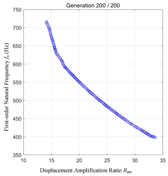
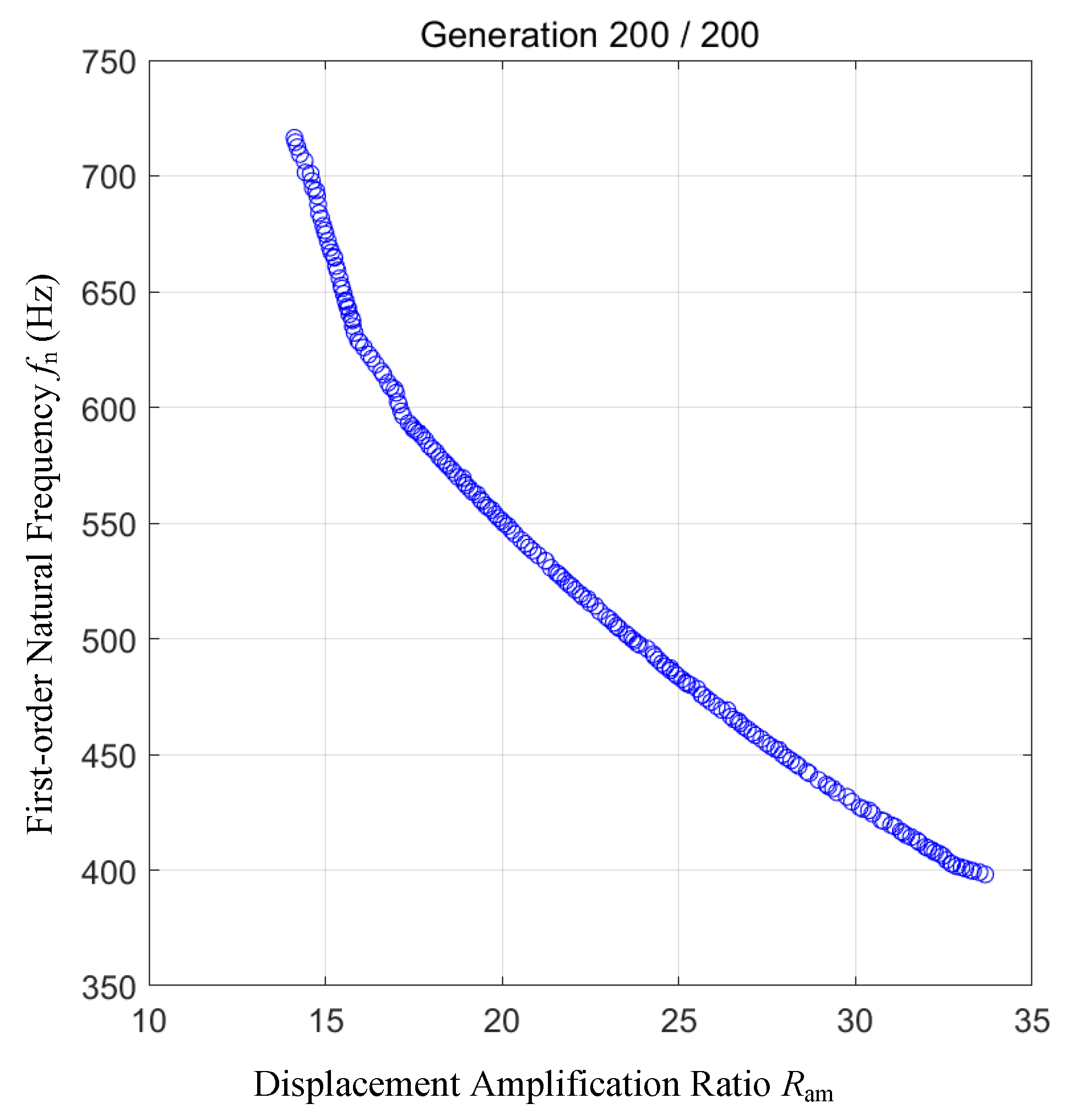
Population size and maximum generation of NSGA-II are set to be 300 and 200, respectively, and after 200 generations, the Pareto front is obtained, as shown in Figure 7. The largest was chosen, and the geometric dimensions of the microgripper are rounded for prototype, as listed in Table 1.
Figure 7.
Pareto Front of the Microgripper in Terms of DAR and FNF.
Table 1.
Geometric parameters of the microgripper obtained by optimization (mm).
In Table 1, = 9 mm, = 3 mm are kept constant, while and are determined from the optimized values of the design variables. In addition, the electrical and mechanical parameters of the PSA adopted in the design are given, as shown in Table 2.
Table 2.
Electrical and mechanical parameters of the PSA [31].
The parameters listed in Table 1 and Table 2 are substituted into the theoretical model to calculate the output displacements of all nodes, among which the displacements of 7 key nodes displacements are presented in Table 3.
Table 3.
Node displacements of the optimized microgripper from the analytical model.
As shown in Table 3, the output displacement of node 25 is −14.342 μm, and the negative sign indicates displacement along the negative Y-axis. The output displacement of single side clamping arm is 431.633 μm, and the unilateral DAR is derived as 30.1. Thus the GS and bilateral DAR of the microgripper from analytical model is 0.863 mm and 60.2, respectively. It can also be seen from the table that the output displacements of two input displacements of both the left and right DLAM, i.e., nodes 28 and 38, 29 and 39, are equal in magnitude and opposite in direction. This indicates that the designed microgripper possesses good symmetry.
Solving Equation (13) yields the first 129 natural frequencies for the corresponding in-plane vibration modes of the microgripper, and the first six natural frequencies are listed in Table 4. The FNF of the microgripper is 433.7 Hz, which is a little larger than the optimization results.
Table 4.
First six natural frequencies of the optimized microgripper from the analytical model (Hz).
5. Finite Element Simulation
To verify the validity of the optimization and the accuracy of the analytical model, the static and dynamic performances of the optimized microgripper are analyzed using commercial finite element analysis (FEA) software (ANSYS 10). 7075 aluminum alloy is assigned to the FEA model with the following material properties: elastic modulus of 71.7 GPa, density of 2700 kg/m3, Poisson’s ratio of 0.33, and yield strength of 505 MPa. Automatic meshing is adopted. The mesh size of the linkages was set to 0.4 mm, whereas the mesh size for the right circular flexure hinge elements was refined from 0.4 mm down to 0.1 mm in steps of 0.1 mm. It was found from multiple simulations that the output displacement converged as the mesh size decreased to 0.1 mm. Accordingly, the mesh size of the right circular flexure hinges and the corresponding simulation results were determined. It is worth noting that the stiffness of the PSA is represented by a spring in the FEA model, and the stiffness value is set to the nominal value in Table 2, i.e., 95 N/μm. The actuating force in the negative direction is applied to the upper surface of the connecting rod.
5.1. Static Performance Simulation
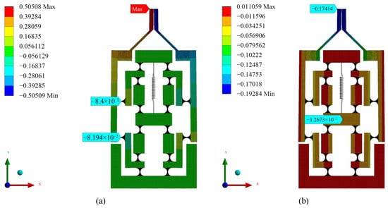
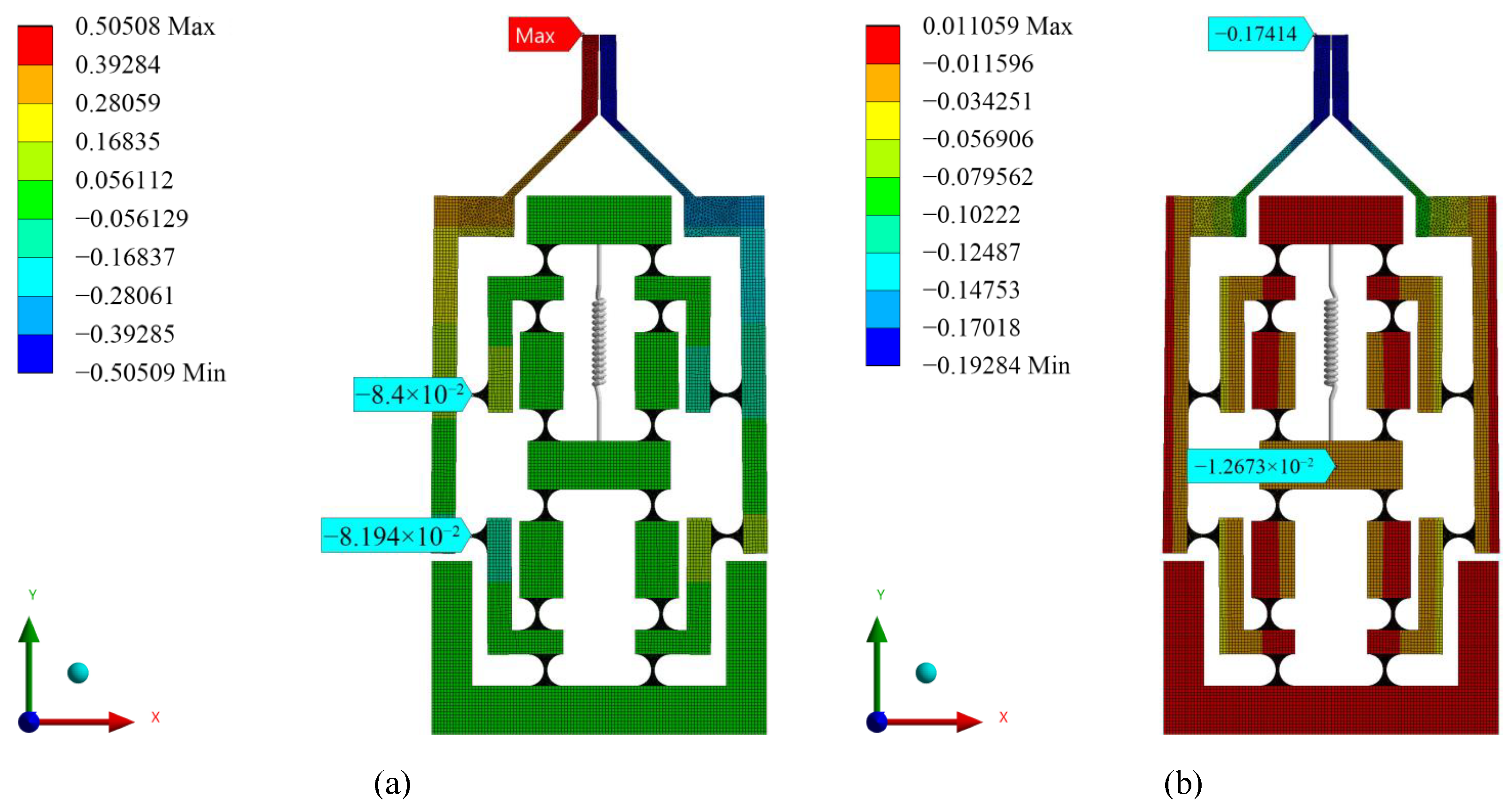
Input and output displacements obtained from static simulation are illustrated in Figure 8. It can be seen from Figure 8a that the maximum output displacement of the left clamping arm is 0.50508 mm, and the two input displacements of the DLAM are 0.0841 mm and −0.081942 mm, respectively. These opposite input displacements indicate that the DLAM can produce a larger output displacement than the conventional lever-type DAM under the same geometrical conditions. This is also the main advantage of the proposed microgripper.
Figure 8.
Output displacements of the microgripper from simulation: (a) along the X-axis; (b) along the Y-axis.
As shown in Figure 8b, the input displacement of the actuating point is −0.012673 mm, the unilateral DAR is 39.9, which is larger than the analytical value.
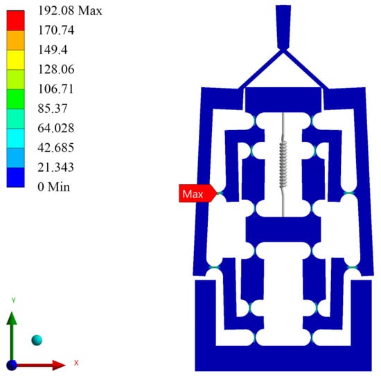
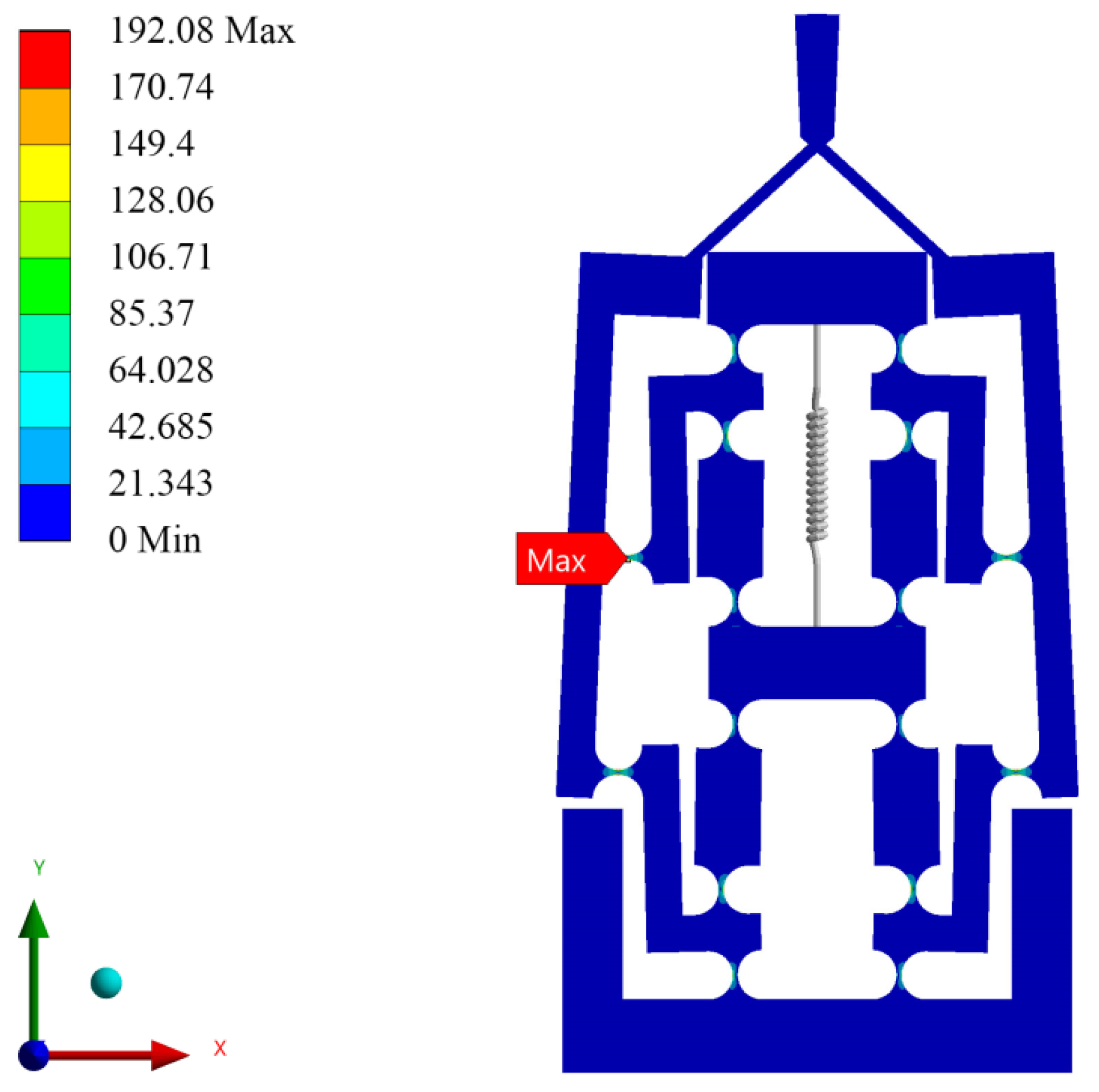
Figure 9 presents the von Mises stress contour of the microgripper. The maximum stress of the entire mechanism occurs at the inner flexure hinge of the DLAM, with a value of 192.08 MPa. The safety factor is approximately 2.6, which satisfies the design requirements.
Figure 9.
Simulated von Mises stress contour.
5.2. Modal Analysis
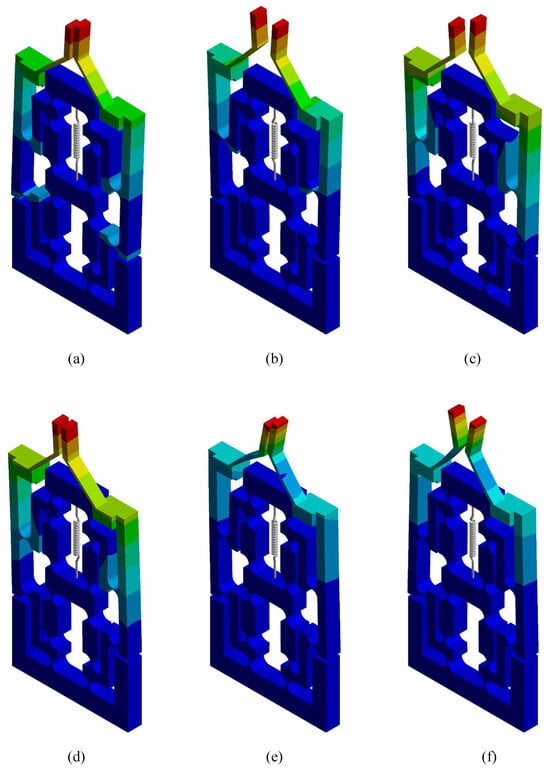
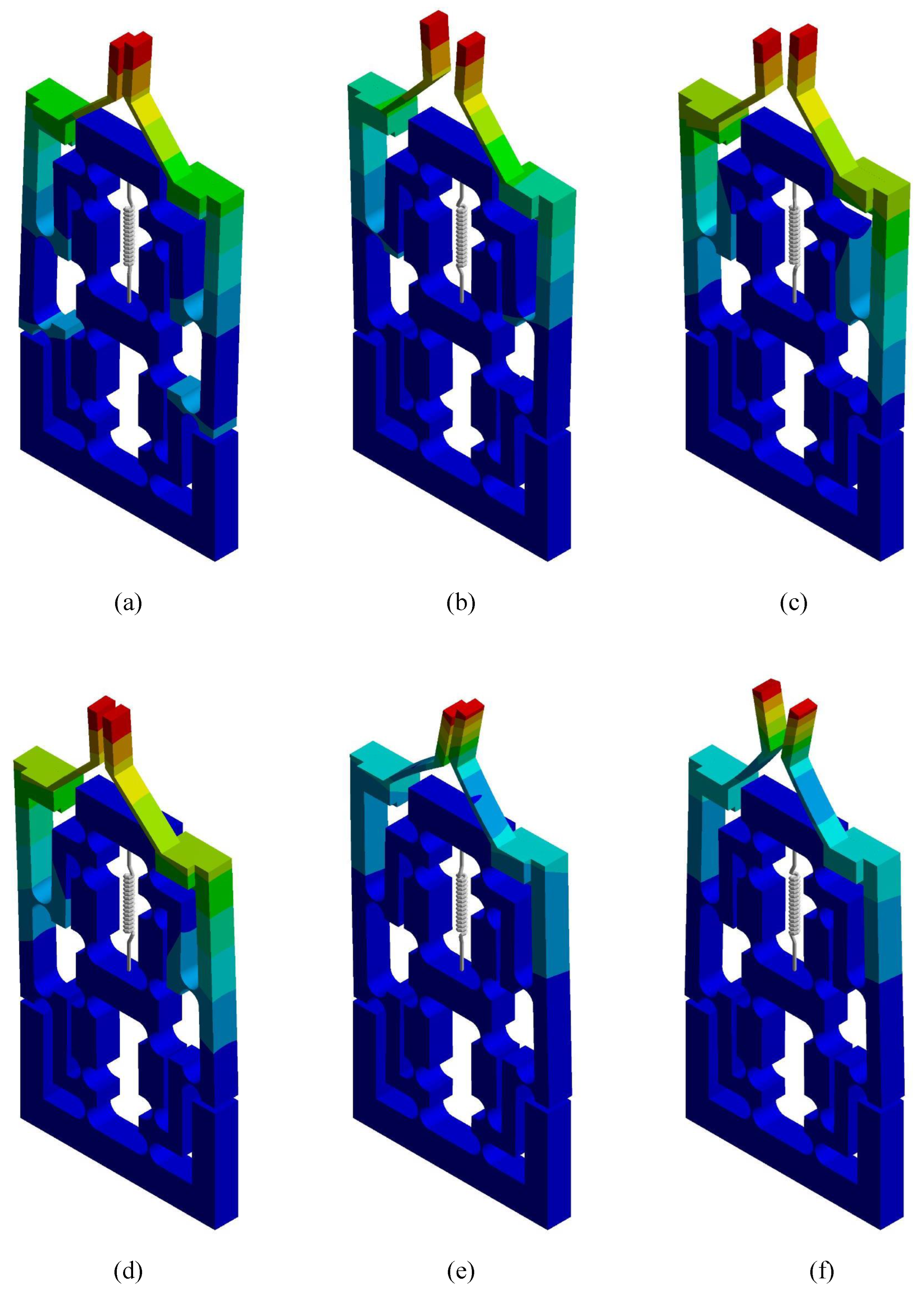
Modal analysis is conducted to obtain the first six natural frequencies of the microgripper. The first six mode shapes are shown in Figure 10a–f, and the corresponding natural frequencies are listed in Table 5. It can be observed from Figure 10a,b that the first two mode shapes correspond to the same and opposite-direction motions of the left and right clamping arms, respectively. The second mode shape represents the clamping motion of the microgripper with a natural frequency of 451.33 Hz, which demonstrates the favorable dynamic performance of the microgripper. The third to fifth mode shapes correspond to out-of-plane vibrations, and the sixth mode is a local mode of the clamping arms.
Figure 10.
The first six mode shapes of the microgripper: (a) mode; (b) mode; (c) mode; (d) mode; (e) mode; (f) mode.
Table 5.
The first six natural frequencies of the microgripper from simulation (Hz).
6. Experiments
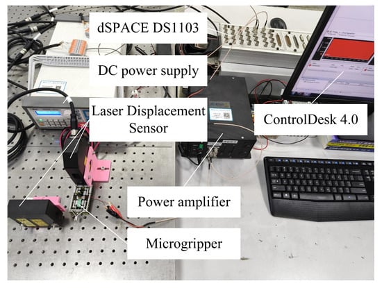
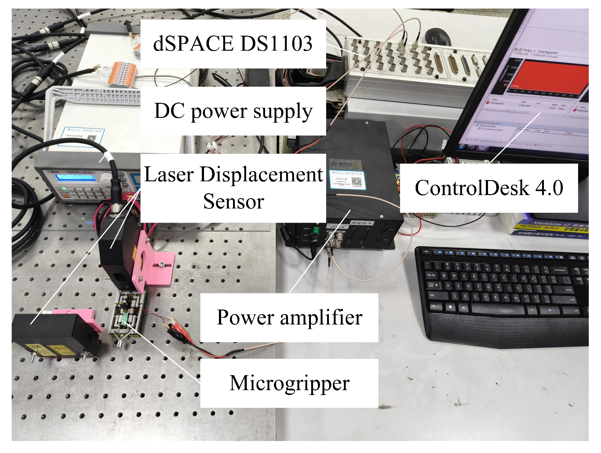
The prototype of the microgripper was machined using Wire-Electrical Discharge Machining (WEDM), and the material was selected as the 7075 aluminum alloy. Then an experimental setup was established, as shown in Figure 11. The PSA employed in the microgripper is the DCS3-070720, a square multilayer piezoelectric ceramic component manufactured by Guangdong DC-piezo Technology Co., Ltd., Guangzhou, China. It is driven by a power amplifier and outputs a driving voltage range of −30 to 150 V, delivers a maximum output force of 1960 N, and exhibits a nominal output displacement of 20 μm. Two laser displacement sensors, specifically the LTP025 and LTP030 models from Wuxi Hongchuan Technology Co., Ltd., Wuxi, China, were adopted for displacement measurement. The LTP025 sensor, featuring a full-scale range of ±1 mm, is employed to monitor the input displacement of the PSA. Meanwhile, the LTP030 sensor, which has a full-scale range of ±3 mm, is utilized to measure the output displacement of the microgripper. All analog input and output signals were connected to the dSPACE DS1103 controller board, and the ControlDesk 4.0 was employed to monitor the control process and record the measurement data.
Figure 11.
Experimental setup.
6.1. Open-Loop Experiments
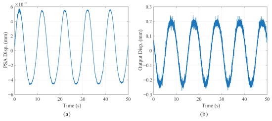
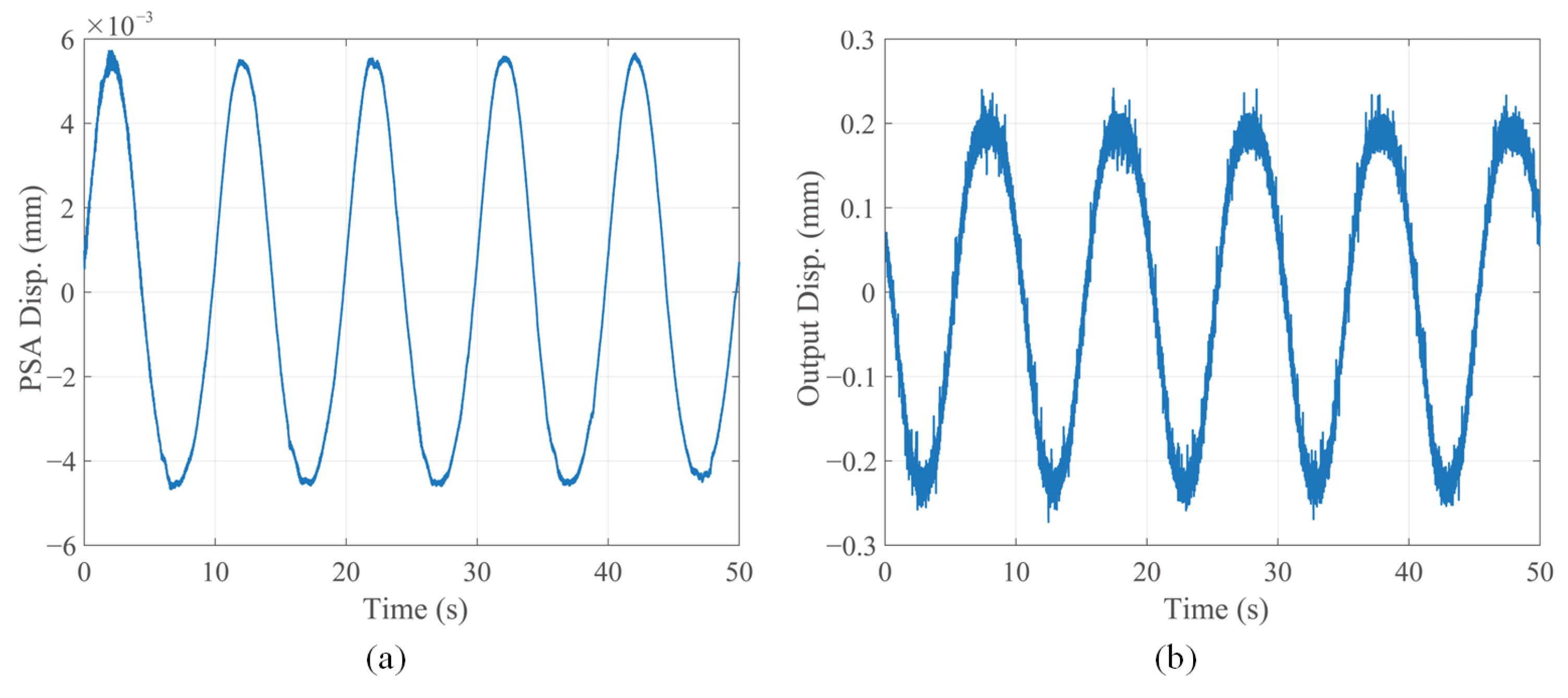
In the open-loop experiments, the GS, DAR, and FNF of the microgripper were characterized. Five sets of sinusoidal voltage signals with amplitudes ranging from 30 V to 150 V and a frequency of 0.1 Hz were applied to the PSA. Subsequently, the input displacement generated by the PSA and the output displacement of the left clamping arm were measured using laser displacement sensors. As shown in Figure 12, when the driving voltage is 150 V, the magnitude of input displacement is about 11 μm, while that of the output displacement is about 450 μm. Due to the high noise level of the laser displacement sensors and the 10-bit analog-to-digital converter of the dSPACE DS1103, it was difficult to determine the true amplitude value. Therefore, step response experiments were further performed to determine the unilateral DAR of the microgripper.
Figure 12.
Displacements under a driving voltage of 150 V: (a) input displacement; (b) output displacement.
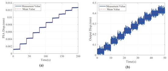
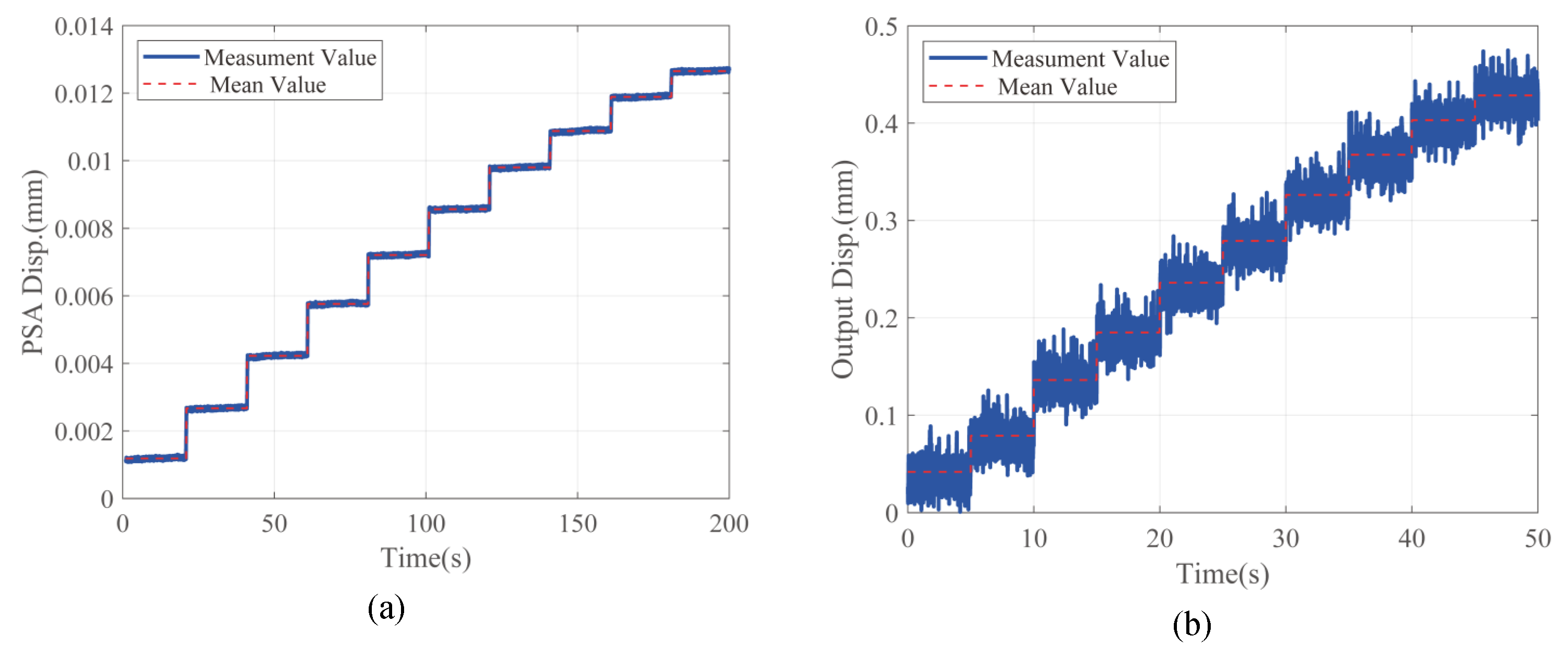
Driving voltages ranging from 15 V to 150 V were applied to the PSA step by step, with a voltage interval of 15 V. Experimental results were acquired via the dSPACE DS1103, and the steady-state values with a time interval of 20 s are shown in Figure 13. As shown in Figure 13a, the step responses decrease as the driving voltages increase. It indicates that the deformation of the microgripper exhibits nonlinear characteristics, which are common under large deformation. The output displacements of the microgripper are illustrated in Figure 13b. Although the levels of random noise and vibration are high, the true displacement value for each step could be obtained using the mean value.
Figure 13.
Step-response experiment results under different driving voltages: (a) input displacements; (b) output displacements.
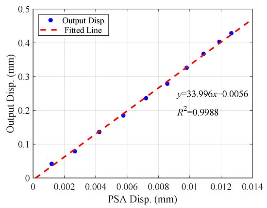
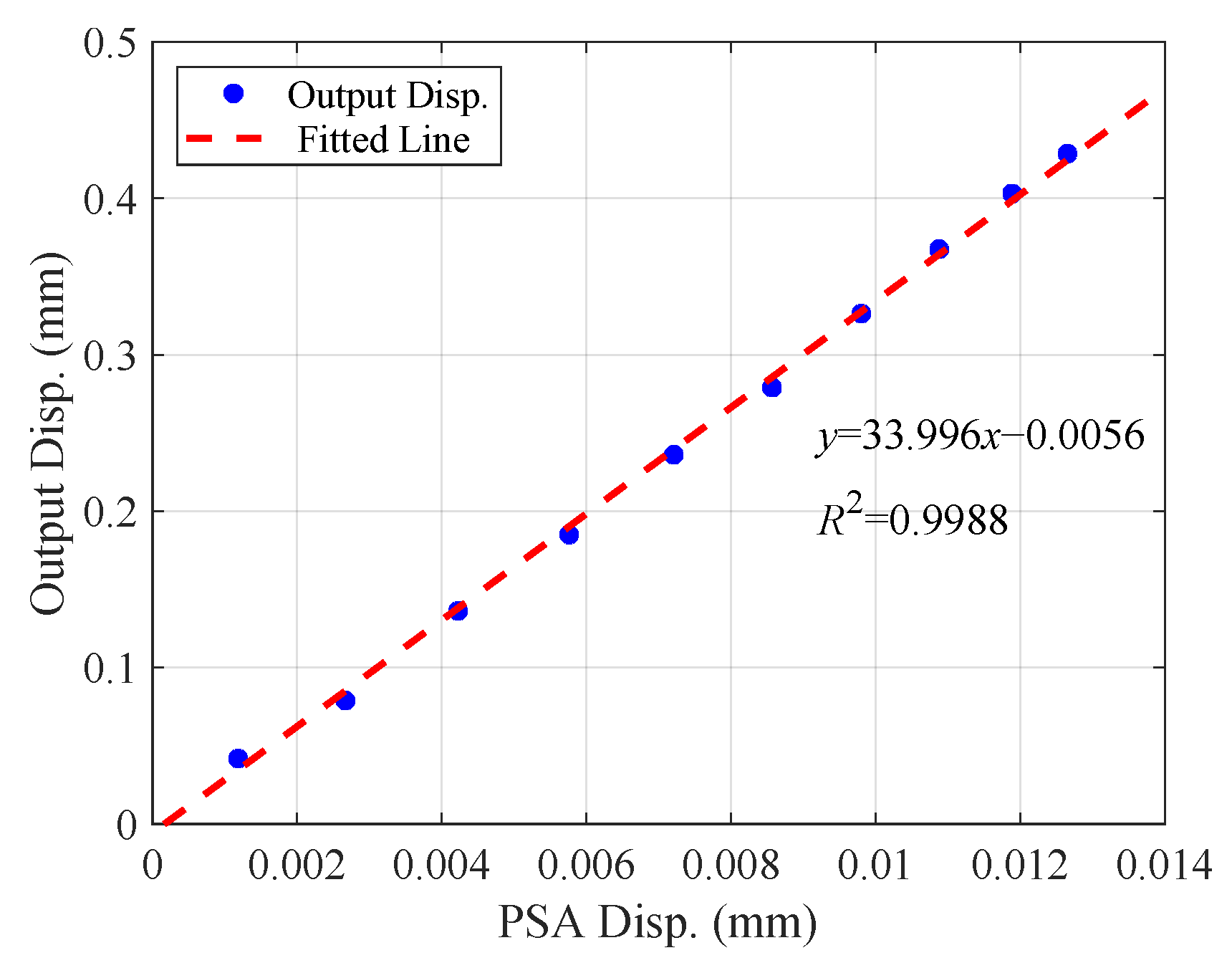
Ten sets of mean values of the input and output displacements are shown in Figure 14, and linear fitting was performed to extract the unilateral DAR of the microgripper. As shown in Figure 14, although the input and output displacements exhibit nonlinearity, the DAR of the microgripper remains linear, and the fitting value is 33.996. Meanwhile, the maximum input and output displacements under a driving voltage of 150 V, determined from the mean values, are 11.8 μm and 428.5 μm, respectively.
Figure 14.
Experimental data of input and output displacements and fitted value of the unilateral DAR.
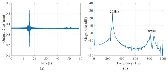
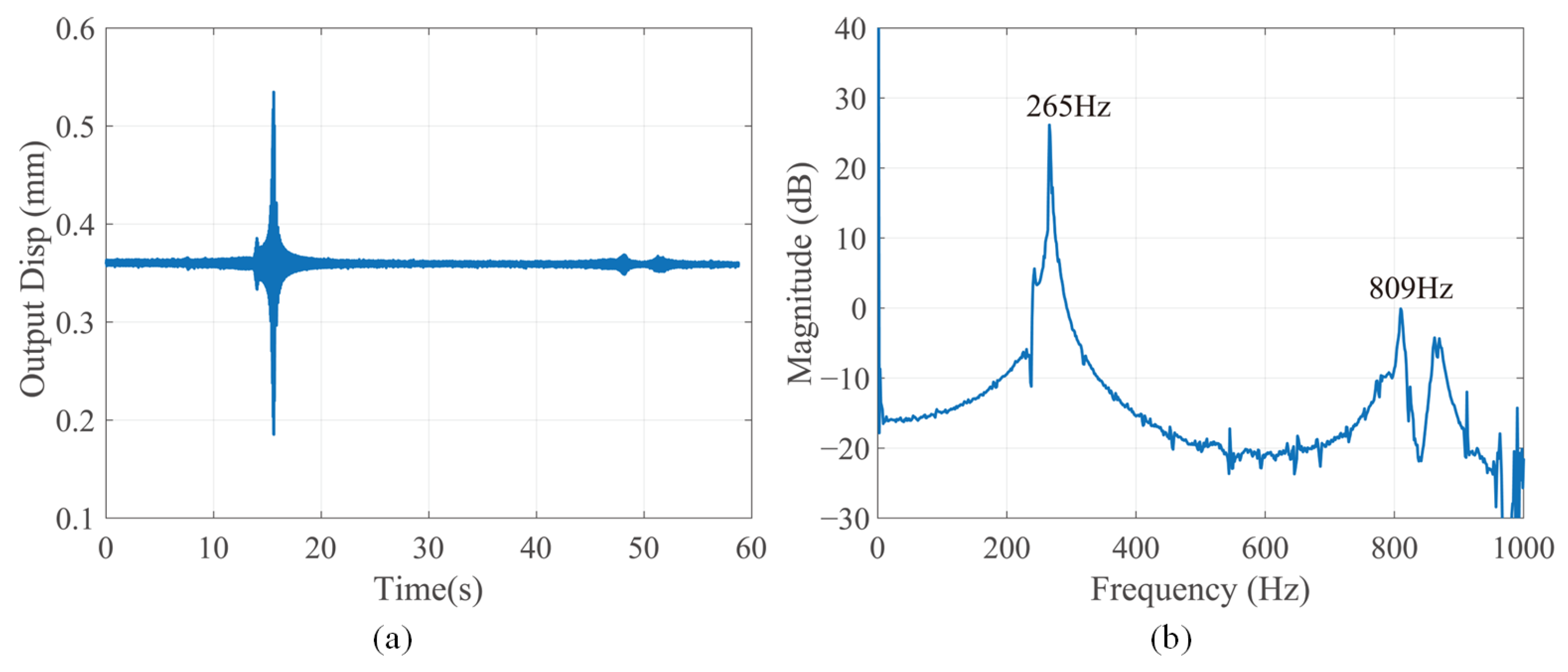
In addition, a sinusoidal sweep test was conducted to acquire the dynamic characteristics of the microgripper. A chirp signal with a linearly increasing frequency from 0.1 Hz to 1000 Hz was applied to the PSA, and the response signal is shown in Figure 15a. Subsequently, discrete Fourier transform (DFT) was adopted to obtain the frequency spectrum of the steady-state response. As shown in Figure 15b, The FNF is approximately 265 Hz, while the higher-mode frequency is 809 Hz.
Figure 15.
Open-loop sinusoidal sweep test: (a) time-domain response; (b) frequency-domain response.
6.2. Close-Loop Experiment
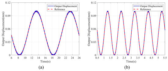
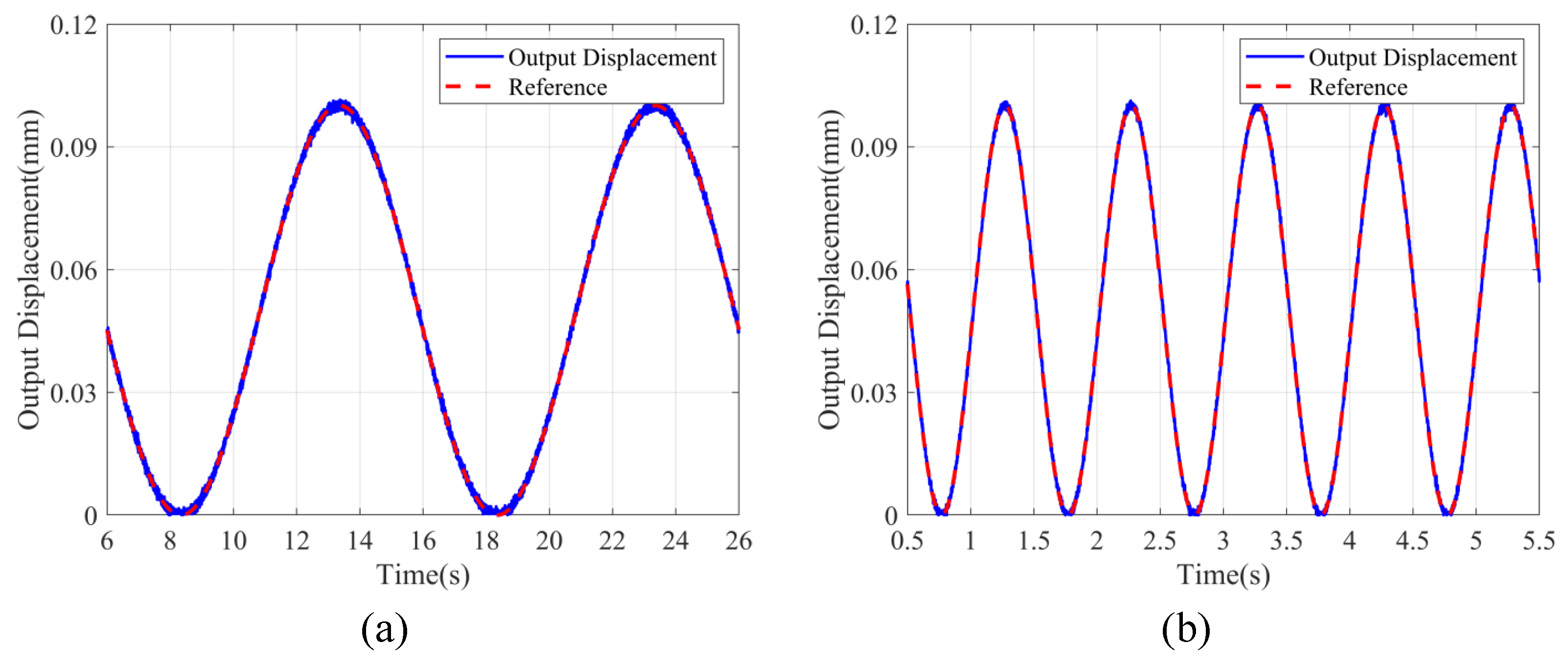
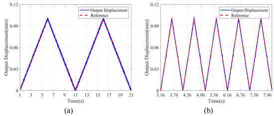
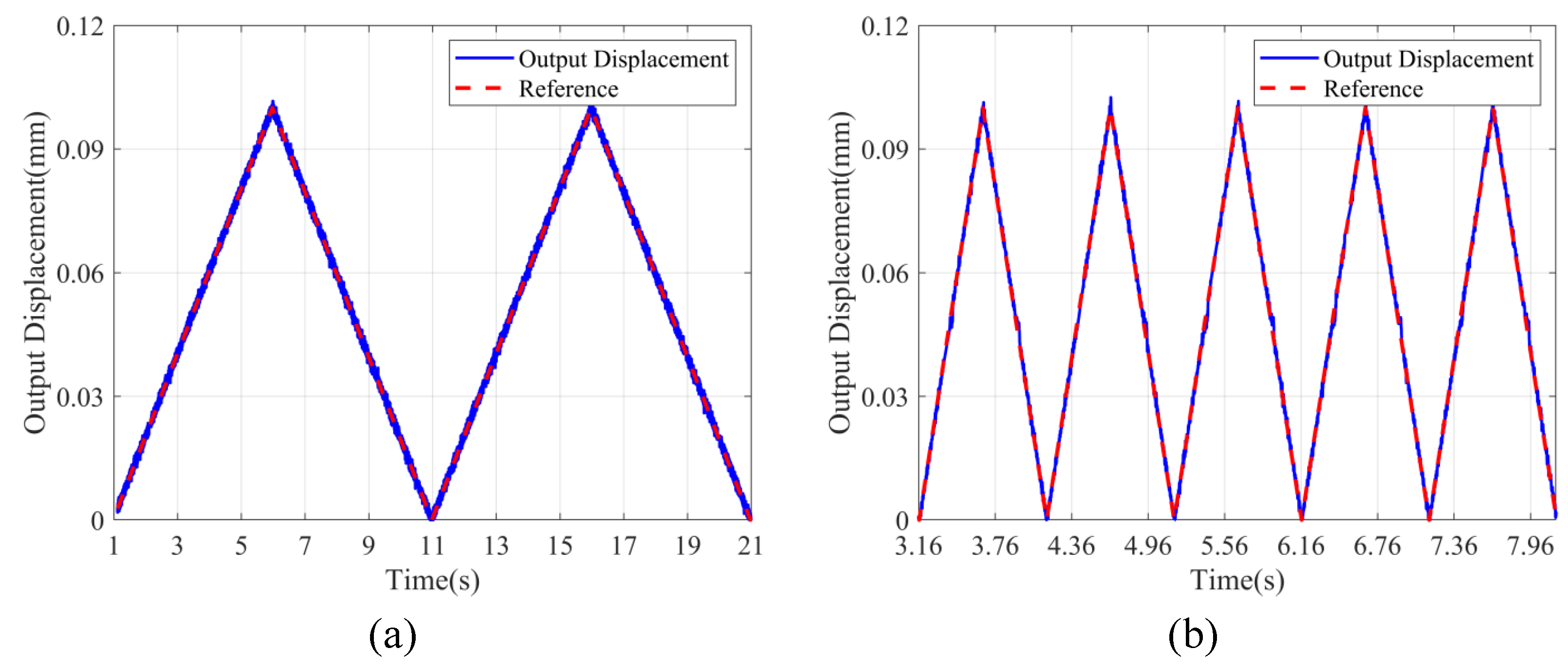
For micromanipulation tasks, precise control over the gripping displacement of the microgripper is essential. Herein, a proportional-integral-derivative (PID) controller was implemented for the microgripper, with control parameters tuned by trial and error. First, two sets of trajectory tracking experiments were carried out. Specifically, sinusoidal and triangular reference trajectories with an amplitude of 100 μm at 0.1 Hz and 1 Hz were used for trajectory tracking tests, and the test results are shown in Figure 16 and Figure 17.
Figure 16.
Sinusoidal trajectory tracking at different frequencies: (a) 0.1 Hz; (b) 1 Hz.
Figure 17.
Triangular-wave trajectory tracking at different frequencies: (a) 0.1 Hz; (b) 1 Hz.
As shown in Figure 16 and Figure 17, the output displacements can well track the reference trajectories at both frequencies of 0.1 and 1 Hz. Furthermore, three tracking performance indices, i.e., the maximum absolute error (), mean absolute error (MAE), and root mean square error (RMSE), were quantitatively investigated. The results are listed in Table 6. From the tabulated results, it can be seen that tracking errors grow with increasing reference frequency, mainly due to the dynamic lag of the piezoelectric actuator and the intrinsic dynamics of the microgripper. Nevertheless, all error values remain small relative to the reference amplitude of 100 μm, demonstrating that the designed microgripper equipped with the PID controller achieves favorable trajectory tracking performance.
Table 6.
Trajectory tracking errors under different waveforms and frequencies (μm).
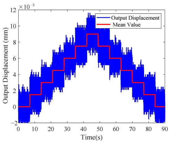
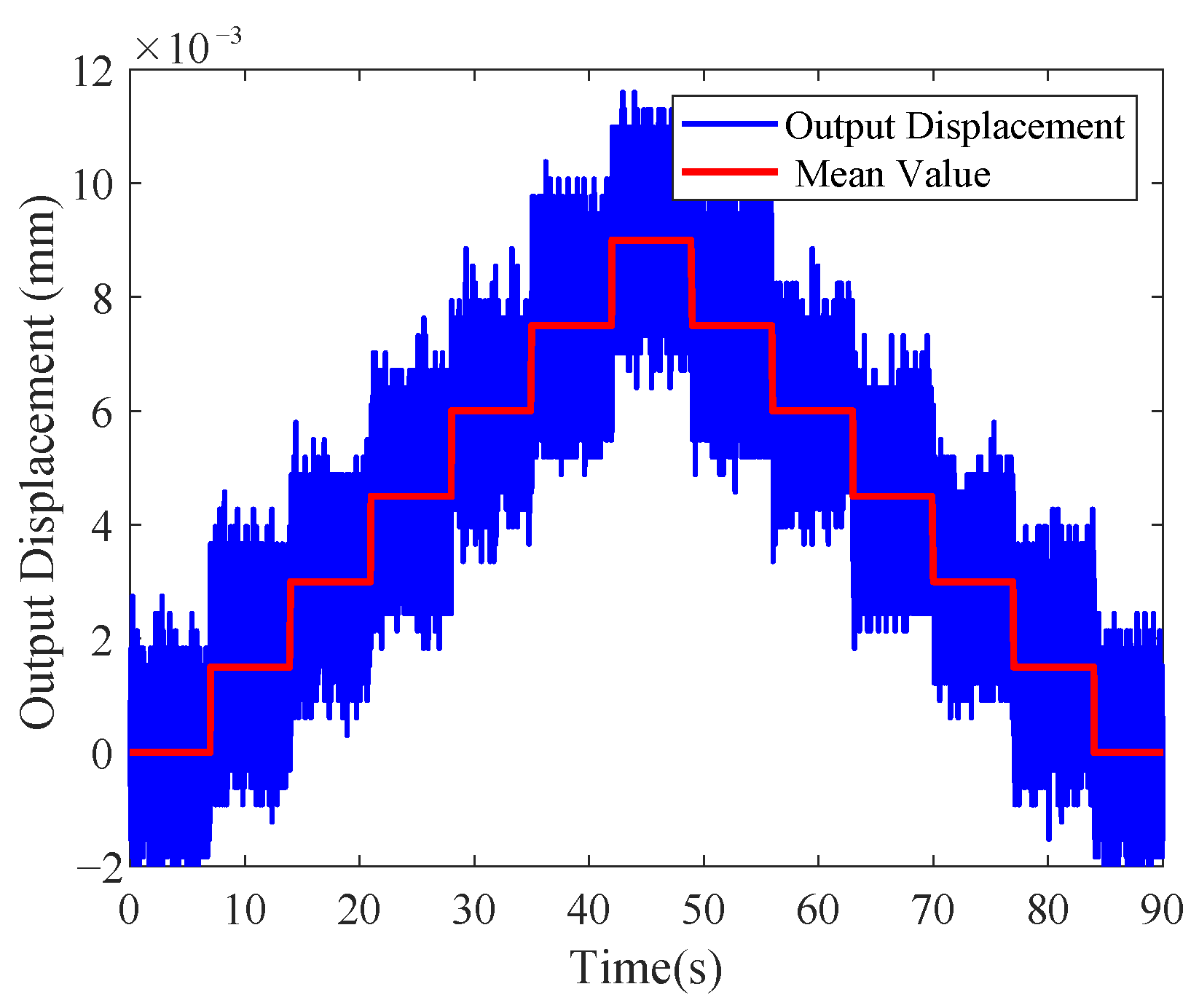
Subsequently, the displacement resolution of the microgripper under PID control was characterized. Specifically, this metric was obtained by gradually decreasing the amplitude of the control voltage signal. As illustrated in Figure 18, despite relatively high noise, the microgripper achieves a displacement resolution of 1.5 μm.
Figure 18.
Close-loop resolution test of the microgripper.
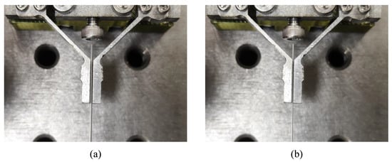
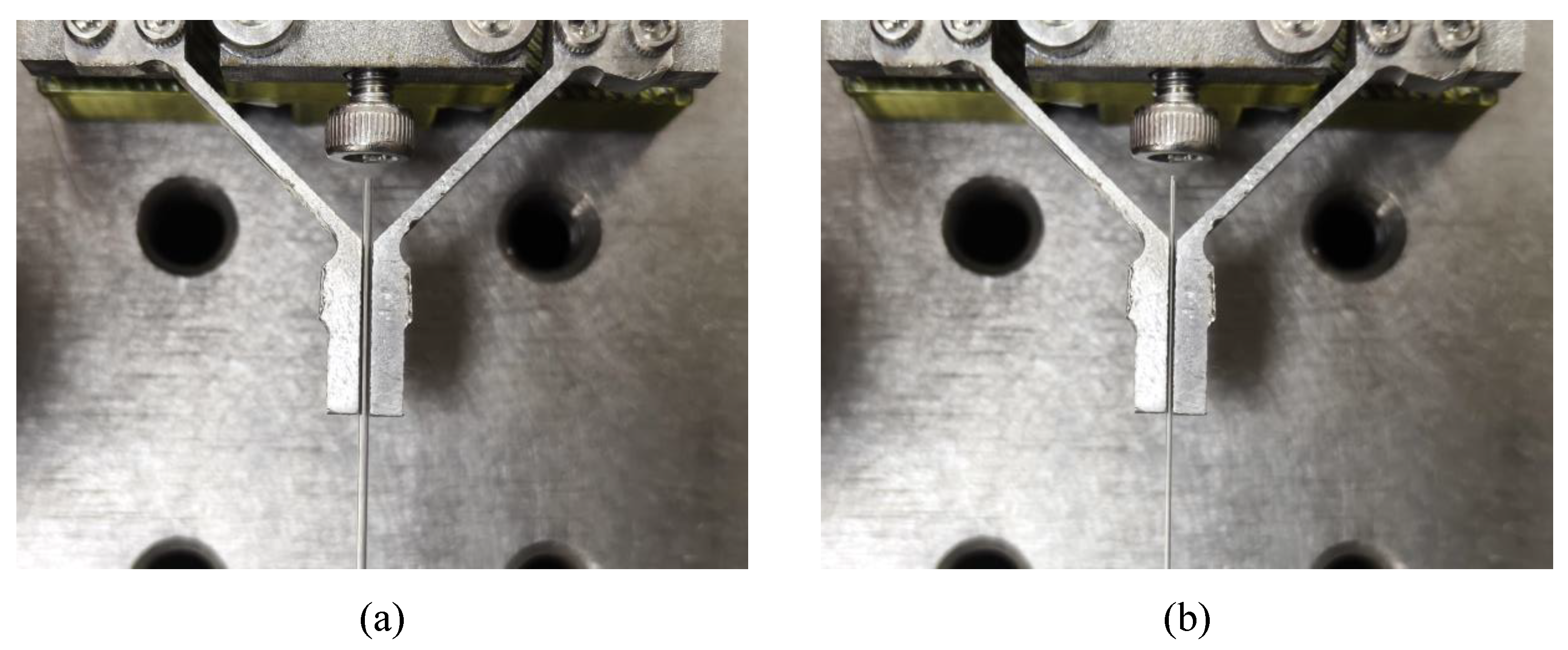
Finally, the developed microgripper was successfully used to grasp glass thin-layer chromatography capillary spotters with inner diameters of 500 μm and 300 μm, as illustrated in Figure 19.
Figure 19.
Grasping glass thin-layer chromatography capillary spotters with different inner diameters: (a) 500 μm; (b) 300 μm.
7. Discussion
7.1. Results Analysis
As outlined in the preceding sections, theoretical modeling, finite element simulations and experiments were carried out for subsequent analysis. Afterwards, the results from these three methods are compared and discussed. The input displacement, output displacement, unilateral DAR, and FNF from different methods are listed, and the relative errors of FEA and experiments (Exp.) with regard to the analytical results are calculated, as shown in Table 7.
Table 7.
Result comparison among different methods.
Compared with the simulation results, the theoretical model predicts larger input and output displacement, with relative errors of 17.7% and 0.73%, respectively. The unilateral DAR predicted by the theoretical model is 30.1, while the fitted experimental value is 33.996, yielding a relative error of 12.9%. The relatively large deviation is attributed to simplifications including the conversion of solid components into beam elements, neglect of the cross-sectional dimensions of linkages, and application of the actuating force at a single node rather than over the contact area between the microgripper and the PSA. In other words, the discretization of the microgripper into beam elements results in greater deformation at the actuating node in theoretical model than that measured from experiments. Accordingly, the theoretical prediction of the unilateral DAR is smaller than the experimental value.
As shown in Figure 2, the connecting rod is discretized into nodes 6, 7, 8, 18, 19, 20, 25 and elements (6), (7), (18), (19), (25), (26). As listed in Table 3, the Y-direction output displacements of node 25 and node 7 (or node 19) are −14.342 μm and −11.565 μm, respectively. This indicates that node 25 undergoes greater deformation than nodes 7 and 19, which agrees with the foregoing analysis. Accordingly, the unilateral DAR is underestimated when the displacement of node 25 is used for calculation. Assume that the mean value of node 25 and node 7 or 19 serve as the input displacement of the PSA, i.e., −12.954 μm, and then the derived unilateral DAR is 33.32, which is agree with the experimental fitted value 33.996 shown in Figure 14.
As shown in Table 7, the FNF from experiments is much lower than the theoretical value, and the relative error reaches 38.9%. Three main factors contribute to these errors. First, the integration of the PSA raises the equivalent mass of the microgripper and modifies its mass and stiffness distribution, potentially lowering the natural frequency. In addition, both contact conditions and preload exert an influence on the natural frequency. Second, manufacturing tolerances, assembly deviations and non-ideal boundary conditions contribute to a reduction in effective stiffness and a consequent drop in natural frequency. Finally, the simplified electromechanical coupling effect of the PSA cannot fully capture the dynamic behavior of the system.
In Table 7, it can be found that the input displacement obtained from FEA is smaller, whereas the output displacement is larger than the analytical prediction. This leads to a considerable discrepancy in the unilateral DAR and the relative error is 32.6%. The primary reason may lies in the nonlinear force–displacement relation induced by large deformation, which is observed in Figure 13. The theoretical model incorporates large deformation based on Timoshenko beam theory, while large deflection is not considered in FEA because of computational cost. Therefore, the small deformation assumption may lead to the substantial discrepancy. Moreover, the FNF obtained from FEA lies between the analytical prediction and the experimental measurement, with a relative error of 17.1% and 26.2%. As shown in Figure 10, a spring with identical stiffness of the PSA is used, and the stiffness effect is equivalently considered but its inertial effect is ignored. This may be the primary reason for this discrepancy.
To summarize the above analysis, the simplified beam representation of the PSA is incorporated into the theoretical model to account for its influence on the mechanism. More specifically, the contact surface is simplified to a single node, and the force–displacement transmission relationship is properly established, enabling the theoretical model to predict the output displacement. Nevertheless, the actual contact condition between the PSA and the mechanism is considerably more complex than this simplified relation, limiting the prediction accuracy of the FNF. Although certain discrepancies are observed in both static and dynamic performance predictions, the results generally validate the feasibility of the proposed modeling method for geometric optimization. Future work will focus on the trade-off between modeling efficiency and accuracy, with particular attention to FNF prediction.
7.2. Performance Analysis
The key performances including GS, DAR, FNF, equivalent stress and area-usage efficiency of various piezoelectric-actuated microgrippers are summarized in Table 8. These results reveal that the proposed microgripper achieves a large GS and DAR, as well as high area-usage efficiency. This further verifies the merits of DLAMs in the design of the piezoelectric-actuated microgripper.
Table 8.
Performance comparison of various piezoelectric-actuated microgrippers.
8. Conclusions
A symmetric piezoelectric-actuated microgripper employing reversed S-R mechanisms and DLAMs is proposed, which achieves a GS of 857 μm, a bilateral DAR of 68, and an FNF of 265 Hz. The mechanical merits of DLAMs are verified and demonstrated. Furthermore, a mechanical model for the proposed microgripper is established. By incorporating the mechanical characteristics of the PSA, the stiffness effect of the actuator on the mechanism is considered. FEA and experiments are performed to validate the developed model. The relative error for the input displacement and output displacement are less than 10.9% and 26.5%, whereas that for the FNF reaches 38.9%. Despite the relatively large modeling error, the established model can still provide useful guidance for the design of piezoelectric-actuated microgrippers, as stiffness matching is incorporated into the design process. In addition, the main sources of these errors are also discussed. Finally, closed-loop control and grasping experiments are conducted to demonstrate the capability of the microgripper for micromanipulation. Future research will be dedicated to further enhancing modeling accuracy and investigating the measurement and control of grasping force. Advanced position/force control strategies will be explored to achieve micromanipulation and microassembly of fragile micro-objects.
Author Contributions
Conceptualization, H.Y. and F.F.; methodology, H.Y.; software, F.X. and Z.Z. (Zhiying Zhu); validation, H.Y., F.F. and H.X.; experiment, F.X., H.X. and Z.Z. (Zhiying Zhu); data curation, H.Y. and F.F.; writing—original draft preparation, H.Y.; writing—review and editing, F.F.; visualization, H.Y. and F.F.; supervision, Z.Z. (Zhifang Zhu) and Q.L. All authors have read and agreed to the published version of the manuscript.
Funding
This research was funded by Jiangxi Province Natural Science Foundation (grant numbers 20232BAB204045 and 20252BAC240139); National Natural Science Foundation of China (grant number 52365005); Science and Technology Project of Jiangxi Provincial Department of Education (grant number, GJJ2201504); Open Fund Project of Jiangxi Province Engineering Research Center of New Energy Technology and Equipment (grant number, JXNE2022-08); Special Funding Program for Graduate Student Innovation in Jiangxi Province (YC2025-S802); University-level doctoral research project (2022kyqd025).
Institutional Review Board Statement
Not applicable.
Informed Consent Statement
Not applicable.
Data Availability Statement
Data available upon the requests from the authors.
Conflicts of Interest
The authors declare no conflict of interest.
References
- Lyu, Z.K.; Xu, Q.S. Recent design and development of piezoelectric-actuated compliant microgrippers: A review. Sens. Actuators A Phys. 2021, 331, 113002. [Google Scholar] [CrossRef] [Scilit]
- Bai, J.; Niu, P.J.; Gu, E.D.; Li, J.M.; Tee, C.A.T. A single micro-LED manipulation system based on microgripper. Nanotech. Precis. Eng. 2024, 7, 023005. [Google Scholar] [CrossRef] [Scilit]
- Zhang, X.M.; Zhu, B.L.; Li, H.; Chen, Z.; Wang, R.X.; Zang, H.Y. Recent advances in compliant precision positioning and manipulating mechanisms. J. Mech. Eng. 2023, 59, 24–43. [Google Scholar] [CrossRef] [Scilit]
- Chen, F.X.; Zhang, Q.J.; Gao, Y.; Dong, W. A review on the flexure-based displacement amplification mechanisms. IEEE Access 2020, 8, 205919–205937. [Google Scholar] [CrossRef] [Scilit]
- Hu, L.Q.; Wang, H.X.; Wang, G.W.; Liang, W.H. Design and analysis of a microgripper for trans-scale clamping based on a compliant multistable mechanism. Rev. Sci. Instrum. 2024, 95, 035121. [Google Scholar] [CrossRef] [Scilit] [PubMed]
- Lyu, Z.K.; Xu, Q.S. Novel design of a piezoelectrically actuated compliant microgripper with high area-usage efficiency. Precis. Eng. 2022, 76, 1–11. [Google Scholar] [CrossRef] [Scilit]
- Iqbal, S.; Shakoor, R.I.; Lai, Y.J.; Malik, A.M.; Bazaz, S.A. Experimental evaluation of force and amplification factor of three different variants of flexure based micro displacement amplification mechanism. Microsyst. Technol. 2019, 25, 4061–4072. [Google Scholar] [CrossRef] [Scilit]
- Dong, W.; Chen, F.X.; Gao, F.T.; Yang, M.; Sun, L.N.; Du, Z.J.; Tang, J.; Zhang, D. Development and analysis of a bridge-lever-type displacement amplifier based on hybrid flexure Hinges. Precis. Eng. 2018, 54, 171–181. [Google Scholar] [CrossRef] [Scilit]
- Saba, R.; Iqbal, S.; Shakoor, R.I.; Saleem, M.M.; Bazaz, S.A. Design and analysis of four-jaws microgripper with integrated thermal actuator and force sensor for biomedical applications. Rev. Sci. Instrum. 2021, 92, 045007. [Google Scholar] [CrossRef] [Scilit] [PubMed]
- Zhu, J.X.; Hao, G.B. Design and test of a compact compliant gripper using the Scott–Russell mechanism. Arch. Civ. Mech. Eng. 2020, 20, 81. [Google Scholar] [CrossRef] [Scilit]
- Niu, H.N.; Fan, P.Q.; Ma, X.P.; Wang, Y.S.; Long, H.B.; Chen, X.G. Design and analysis of a novel symmetric compliant amplified piezoelectric microgripper. Eng. Res. Express 2026, 8, 115524. [Google Scholar] [CrossRef] [Scilit]
- Ozarkar, R.R.; Salunke, N.P.; Damle, P.G.; Shukla, R.; Ansari, K.B. Design and optimization of miniaturized actuation system with systematic dual-output compliant displacement amplifcation. Actuators 2026, 15, 244. [Google Scholar] [CrossRef] [Scilit]
- Li, J.J.; Chen, G.M. Optimal Design of a compliant two-stage differential displacement amplification mechanism. Chin. J. Mech. Eng. 2019, 55, 21–28. [Google Scholar]
- Cui, L.Y.; Zhu, H.N.; Deng, X.F.; Chai, Y.Y. Design and implementation of flexible four-bar-mechanism based long-stroke micro-gripper. Actuators 2025, 14, 338. [Google Scholar] [CrossRef] [Scilit]
- Fan, W.; Jin, H.X.; Fu, Y.C.; Lin, Y.Y. A type of symmetrical differential lever displacement amplification mechanism. Mech. Ind. 2021, 22, 5. [Google Scholar] [CrossRef] [Scilit]
- Hou, B.B.; Tong, Y.C.; Liu, P.B.; Lu, S.S.; Xiao, G.C.; Yan, P. Development, modeling and analysis of a differential lever-bridge amplification mechanism. Proc. Inst. Mech. Eng. C J. Mech. Eng. Sci. 2024, 238, 8683–8697. [Google Scholar] [CrossRef] [Scilit]
- Du, H.C.; Wang, Y.; Deng, Z.L. Optimal design and analysis of differential displacement three-degree-of-freedom flexible micro-positioning platform. J. Liaoning Petrochem. Univ. 2022, 42, 66–72. [Google Scholar]
- Wu, H.Q.; Chen, G.M. A flexure-based displacement reducer capable of achieving very large reduction ratio. Mech. Mach. Theory 2022, 170, 104658. [Google Scholar] [CrossRef] [Scilit]
- Wu, H.Q.; Chen, G.M. An inverted differential mechanism capable of achieving very large amplification ratio: Design and control. IEEE Trans. Autom. Sci. Eng. 2025, 22, 7546–7555. [Google Scholar] [CrossRef] [Scilit]
- Sun, X.T.; Tang, Z.Z.; Yang, S.; Zhu, Y.H.; Deng, Q.W.; Chen, W.H. Design of a large-stroke compliant gripper with position and force sensing for precision grasping. Smart Mater. Struct. 2025, 34, 035034. [Google Scholar] [CrossRef] [Scilit]
- Liu, C.X.; Wang, K.F.; Duan, W.W.; Zhong, X.Q. Research on piezoelectric microgripper based on differential amplification mechanism. Piezoelectr. Acoustoopt. 2026, 48, 262–267. [Google Scholar]
- Iqbal, S.; Malik, A. A review on MEMS based micro displacement amplification mechanisms. Sens. Actuators A Phys. 2019, 300, 111666. [Google Scholar] [CrossRef] [Scilit]
- Wu, S.L.; Gao, H.C.; Ling, M.X.; Pan, M.Q.; Chen, T. Compliance analysis of transversely asymmetric flexure hinges for use in a piezoelectric Scott-Russell microgripper. Precis. Eng. 2024, 91, 95–106. [Google Scholar] [CrossRef] [Scilit]
- Howell, L.L.; Magleby, S.P.; Olsen, B.M. Handbook of Compliant Mechanisms; John Wiley & Sons: Chichester, UK, 2013. [Google Scholar]
- Lobontiu, N. Compliance-based matrix method for modeling the quasi-static response of planar serial flexure-hinge mechanisms. Precis. Eng. 2014, 38, 639–650. [Google Scholar] [CrossRef] [Scilit]
- Yu, H.T.; Zhang, C.; Yang, B.; Chen, S.L.; Fang, Z.J.; Li, R.; Yang, G.L. The design and kinetostatic modeling of 3PPR planar compliant parallel mechanism based on compliance matrix method. Rev. Sci. Instrum. 2019, 90, 045102. [Google Scholar] [CrossRef] [Scilit] [PubMed]
- Ling, M.X.; Cao, J.Y.; Jiang, Z.; Lin, J. A semi-analytical modeling method for the static and dynamic analysis of complex compliant mechanism. Precis. Eng. 2017, 52, 64–72. [Google Scholar] [CrossRef] [Scilit]
- Ling, M.X.; Cao, J.Y.; Howell, L.L.; Zeng, M.H. Kinetostatic modeling of complex compliant mechanisms with serial parallel substructures: A semi analytical matrix displacement method. Mech. Mach. Theory 2018, 125, 169–184. [Google Scholar] [CrossRef] [Scilit]
- Ling, M.X.; Howell, L.L.; Cao, J.Y.; Chen, G.M. Kinetostatic and dynamic modeling of flexure-based compliant mechanisms: A survey. Appl. Mech. Rev. 2020, 72, 030802. [Google Scholar] [CrossRef] [Scilit]
- Chen, G.M.; Ma, Y.K.; Li, J.J. A tensural displacement amplifier employing elliptic-arc flexure hinges. Sens. Actuators A Phys. 2016, 247, 307–315. [Google Scholar] [CrossRef] [Scilit]
- Zhang, Y.K.; Lu, T.F. On an equivalent model of multi-layer piezoelectric actuators for facilitating finite element simulations. Microsyst. Technol. 2019, 25, 4455–4464. [Google Scholar] [CrossRef] [Scilit]
- Lyu, Z.K.; Xu, Q.S. Design and testing of a new piezoelectric-actuated symmetric compliant microgripper. Actuators 2022, 11, 77. [Google Scholar] [CrossRef] [Scilit]
- Wang, F.J.; Liang, C.M.; Tian, Y.L.; Zhao, X.Y.; Zhang, D.W. Design of a piezoelectric-actuated microgripper with a three-stage flexure-based amplification. IEEE/ASME Trans. Mechatron. 2015, 20, 2205–2213. [Google Scholar] [CrossRef] [Scilit]
- Shi, C.Y.; Dong, X.Y.; Yang, Z. A microgripper with a large magnification ratio and high structural stiffness based on a flexure-enabled mechanism. IEEE/ASME Trans. Mechatron. 2021, 26, 3076–3086. [Google Scholar] [CrossRef] [Scilit]
- Shi, Q.; Yu, Z.Q.; Wang, H.P.; Sun, T.; Huang, Q.; Fukuda, T. Development of a highly compact microgripper capable of online calibration for multisized microobject manipulation. IEEE Trans. Nanotechnol. 2018, 17, 657–661. [Google Scholar] [CrossRef] [Scilit]

Disclaimer/Publisher’s Note: The statements, opinions and data contained in all publications are solely those of the individual author(s) and contributor(s) and not of MDPI and/or the editor(s). MDPI and/or the editor(s) disclaim responsibility for any injury to people or property resulting from any ideas, methods, instructions or products referred to in the content. |
© 2026 by the authors. Licensee MDPI, Basel, Switzerland. This article is an open access article distributed under the terms and conditions of the Creative Commons Attribution (CC BY) license.