


Abstract
To address the problem of insufficient shear bearing capacity of highway reinforced concrete (RC) T-beams, this paper systematically conducts a comparative study on the shear performance of RC T-beams strengthened with UHPC-CFP toughened composite plates of different configurations, and proposes a shear strengthening method using UHPC-CFP toughened composite plates. Comparative tests on different strengthening configurations are carried out. Meanwhile, a finite element numerical model is established to compare with the experimental results, analyze the influences of different strengthening schemes on the shear bearing capacity and mechanical properties of the beams, reveal the shear strengthening mechanism, and put forward a recommended formula for calculating the shear bearing capacity. The results show that after the diagonal cracks appeared in Beam T-0, they propagated rapidly from the support to the loading point. Beam T-1 had more diagonal cracks in the concrete between the UHPC-CFP toughened composite strips, while Beam T-2 had fewer. Fine cracks occurred in the UHPC-CFP toughened composite strips of Beams T-1 and T-2, whereas no cracking was observed in the UHPC composite rectangular plate of Beam T-3. The shear capacity of all strengthened beams was improved, with increases of 27.0%, 40.5%, and 43.2% for Beams T-1, T-2, and T-3, respectively. Beam T-3 exhibited the maximum deflection, and the strengthening configuration of Beam T-2 was determined to be the optimal. The carbon fiber strips embedded in UHPC effectively delayed the propagation of cracks in the UHPC plate and played the role of “reinforcement”. The truss–arch model theory is also applicable to the shear mechanism of concrete T-beams strengthened with UHPC-CFP toughened composite plates. Verification of Beams T-2 and T-3 using the proposed formula for shear design of strengthened beams showed that the average ratio of the calculated shear capacity to the experimental value was 0.87, indicating the reliability of the calculation results.
1. Introduction
With the increasing highway traffic volume and the extension of service life, existing medium- and small-span highway bridges generally face problems such as insufficient shear capacity and web shear cracking. This phenomenon is particularly prominent in reinforced concrete T-beams, which are commonly used as medium- and small-span structures, and has seriously affected the service resilience and service life of the bridges. At present, common shear strengthening methods mainly include bonded steel plate strengthening, bonded fiber-reinforced composite (FRP) strengthening, external prestressing strengthening, section enlargement strengthening, and steel plate–concrete composite strengthening [1,2,3,4]. However, these traditional strengthening methods are prone to problems such as carbon fiber sheet debonding and steel plate corrosion. Additionally, they have high construction difficulty, long construction period, high cost, and unsatisfactory effectiveness. Therefore, research on new materials and new methods for shear strengthening has become an inevitable trend. Against this backdrop, the innovative combination of different high-performance materials to construct new types of structures or reinforcement systems with both excellent mechanical properties and construction convenience has become an important research direction. For example, Tian et al. [5] achieved performance self-diagnosis of materials under temperature–load coupling by combining self-sensing functions with ECC; and Fu et al. [6,7] significantly improved the bearing performance and durability of seawater sea–sand concrete columns under axial load through the combination of FRP, steel, and concrete. These studies provide new ideas and paradigms for addressing traditional structural challenges through “material combination.”
The concept of ultra-high-performance concrete (UHPC) was first proposed by Danish scholar De Larrard and Sedran [8] in 1994. Owing to the incorporation of mineral admixtures such as silica fume and fly ash, as well as steel fibers, this material exhibits ultra-high mechanical properties including compressive strength and tensile strength while also possessing excellent corrosion resistance and durability [9,10,11,12]. Currently, as a new type of high-performance material, it has been widely used in fields such as public buildings, ports, and basic materials for bridge and tunnel engineering [13,14,15,16]. Meanwhile, various countries have gradually formulated a series of relevant standard specifications and technical guidelines. However, with the continuous expansion of UHPC application fields, understanding its material and engineering properties has become the key to ensuring the smooth application of UHPC in engineering projects. For this reason, scholars at home and abroad have carried out extensive relevant research.
Zerfu, K. et al. [17] proposed a modeling method for UHPC components combined with different concrete material models in ABAQUS. This method captures the complex fracture and post-cracking response of the material, realizes accurate numerical prediction of the shear performance of UHPC, and is applied to design and structural applications. Zhou, M. et al. [18] investigated the interface shear behavior of monolithically cast UHPC push-off specimens under combined shear and lateral loads. Existing shear strength estimation models were compared and evaluated, providing insights into the shear transfer mechanism of unreinforced UHPC interfaces under different stress conditions. Wu, P. et al. [19] studied the shear transfer behavior of UHPC through push-off tests using Z-shaped specimens, and discussed the effects of micro steel fiber volume ratio and stirrup reinforcement ratio on the shear strength, shear slip, and shear crack width of UHPC. Mirzaaghabeik, H. et al. [20,21] compared the effects of synthetic fibers and steel fibers on the shear capacity of UHPC through numerical modeling, and the research results provide valuable insights for improving existing standards. Tayeh, B and Dziomdziora, P. et al. [22,23] found through research that hybrid synthetic fibers had a significant impact on the mechanical properties of UHPC, and the combination of hybrid synthetic fibers was a key aspect in developing new characteristics of ultra-high-strength concrete. Xu et al. [24] investigated the effects of manganese slag (MS) on fluidity, plastic viscosity, and yield shear stress, and measured the flexural strength, compressive strength, and dry shrinkage of UHPC containing MS. The results showed that the compactness of UHPC could be improved by adding MS. Hasnat, A. [25] investigated the freeze–thaw resistance of non-proprietary ultra-high-performance concrete (UHPC) with varying fiber contents and types. The results indicate that the addition of steel fibers positively enhances the freeze–thaw resistance of UHPC. Pourbaba et al. [26] studied the designed compressive strength of UHPC through comparative experiments and proposed a new strength design criterion for UHPC. Zhu et al. [27] conducted bending tests on UHPC-normal concrete (NC) composite structures, discussed the damage modes, load-deflection relationships, and strength, and clarified the interfacial tensile strength and crack distribution pattern of UHPC-NC composite structures. Paschalis, A.S. [28] conducted an extensive experimental study on full-scale reinforced concrete (RC) beams strengthened with ultra-high-performance fiber-reinforced concrete (UHPFRC) layers. He added additional UHPFRC layers with and without reinforcement to the RC beams, and verified the effectiveness of this strengthening technology through flexural tests. Al-Osta et al. [29] considered the effects of different interface treatment methods and different strengthening positions on the beam strengthening effect, and carried out research on UHPC strengthening of reinforced concrete beams. Zhu et al. [30] proposed a strengthening technology combining high-strength steel wire mesh with UHPC to address the challenge of insufficient load-bearing capacity of existing structures.
To summarize, relevant scholars have conducted extensive research on the mechanical properties and engineering applications of ultra-high-performance concrete (UHPC) with different admixtures, fully confirming that UHPC possesses significant potential and application value in the field of structural strengthening due to its excellent mechanical properties and durability. However, for specific scenarios such as the shear strengthening of small- and medium-span reinforced concrete (RC) T-beams—where strict requirements are imposed on the self-weight, thickness, and construction convenience of strengthening materials—there is still a need to further develop more efficient, lightweight, and easy-to-implement new forms of UHPC strengthening. In this study, a shear strengthening method for T-beams using ultra-high-performance concrete (UHPC)–carbon fiber plate (CFP) toughened composite plates was proposed. Comparative tests on different shear strengthening configurations of UHPC-CFP toughened composite plates were carried out, and a finite element (FE) numerical model of the test beams was established. The effects of different strengthening configurations on the shear capacity and mechanical properties of the beams were compared and analyzed, the strengthening mechanism was revealed, and a proposed formula for calculating the shear capacity of the strengthened beams was further put forward.
2. Experimental Overview
2.1. Properties of Test Materials
- (1)
- UHPC
The UHPC mixture was proportioned by mass with a ratio of UHPC dry blend (Shanghai Fupei New Material Technology Co., Ltd., Shanghai, China)/steel fiber (0.2 × 13 mm) (Shanghai Fupei New Material Technology Co., Ltd.)/water = 1000 kg:90 kg:95 kg. Specimen casting was carried out in summer. Owing to the good fluidity and self-compacting property of UHPC, the cast specimens were covered with plastic film and watered three times per day, and formwork removal was conducted on the third day. After demolding, the specimens were covered with geotextile, watered three times daily, and cured for 28 days.
In accordance with the specifications and methods outlined in the “Reactive Powder Concrete” standard (GB/T 31387-2015) [31], cubic compressive strength was tested on 100 × 100 × 100 mm3 specimens; modulus of elasticity and prismatic compressive strength on 100 × 100 × 300 mm3 prismatic specimens; flexural strength on 100 ×100 × 400 mm3 prismatic specimens; and “dog-bone specimens” were prepared for tensile strength testing. The tensile and compressive test results of UHPC are listed in Table 1.
Table 1.
UHPC tensile and compressive properties.
- (2)
- Carbon fiber plates
In accordance with the specifications and test methods stipulated in Test Method for Tensile Properties of Fiber-Reinforced Plastics (GB/T 1447-2005) [32], rectangular carbon fiber composite sheets were prepared by impregnating carbon fiber cloth (Jiagu Boshi Construction Technology Co., Ltd., Shanghai, China) with resin adhesive (Jiagu Boshi Construction Technology Co., Ltd., Shanghai, China). The sheets had a length of 250 mm and a width of 25 mm, and five sets of tensile tests were conducted in total. The test results are presented in Table 2.
Table 2.
Tensile test results of carbon fiber plates.
- (3)
- Normal concrete and reinforcement bars
The test beams were made of C40 concrete, which was proportioned in accordance with standards (JGJ 55-2011 and GB 50164-2011) [33,34]. The main components of the concrete and their dosages per cubic meter are presented in Table 3. To ensure the material properties of the concrete in each test beam, companion specimens were cast simultaneously with the beams in accordance with the specifications and test methods presented in Standard for Test Methods of Physical and Mechanical Properties of Concrete (GB/T 50081-2019) [35]. Cube specimens of 150 × 150 × 150 mm3 and prismatic specimens of 100 × 100 × 400 mm3 and 150 × 150 × 300 mm3 were prepared to measure the standard cubic compressive strength, flexural strength, prismatic compressive strength, and modulus of elasticity of the concrete, respectively. The test results are shown in Table 4. HRB400 deformed reinforcing bars from the same batch as the test beams were selected, and test specimens with a length of 500 mm were prepared. Tensile tests were performed in accordance with the specifications and procedures specified in Metallic materials—Tensile testing—Part 1: Method of test at room temperature (GB/T 228.1-2010) [36]. The test results are presented in Table 5.
Table 3.
Mix proportion of C40 normal concrete (kg/m3).
Table 4.
Concrete test results.
Table 5.
Reinforcement bar test results.
2.2. Design of Test Beams and Strengthening Schemes
A total of five test T-beams with the same dimensions were designed for the experiment. Each beam had a total length of 2600 mm, a calculated span of 2400 mm, a height of 380 mm, a flange width of 350 mm, a flange thickness of 70 mm, and a web thickness of 120 mm. The concrete strength grade was C40. The longitudinal reinforcement consisted of three HRB400 hot-rolled ribbed bars with a diameter of 18 mm (φ18), while both the stirrups and erection reinforcement were HRB400 hot-rolled ribbed bars with a diameter of 8 mm (φ8). The stirrup spacing was 200 mm, and the stirrup ratio was 0.4%. The dimensions and reinforcement details of the test beams are shown in Figure 1.
Figure 1.
Dimensions and reinforcement details of test beams (mm).
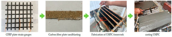
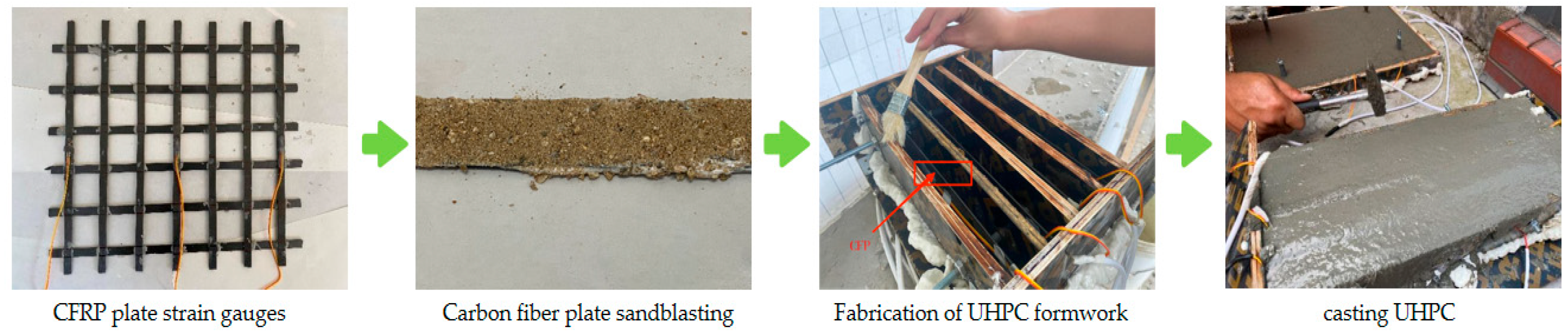
To fabricate the UHPC-CFP toughened composite plate, carbon fiber strips with widths of 10 mm, and lengths of 310 mm and 440 mm were first prepared and assembled into a grid form using carbon fiber structural adhesive (Jiagu Boshi Construction Technology Co., Ltd., Shanghai, China). Then, 120-20AA strain gauges were bonded at the centers of the prepared CFRP strips to measure the strain development of the CFRP strips throughout the loading test. To improve the bonding performance between the carbon fiber plates and the UHPC cast in situ, two-component modified epoxy resin structural adhesive was applied to the surface of the carbon fiber plates, followed by sandblasting treatment to achieve a surface roughness Ra of 40–80 μm. Subsequently, a rectangular UHPC formwork with a width of 310 mm, length of 440 mm and thickness of 30 mm was manufactured, and the carbon fiber grid was fixed in the formwork. Foam adhesive (SKSHU Paint Co., Ltd., Fujian, China) was used to seal the fine gaps of the assembled formwork. Finally, release agent was applied to the formwork to facilitate demolding of the UHPC reinforcement layer and ensure a neat surface finish of the specimen. The fabrication process of the UHPC-CFP toughened composite plate is illustrated in Figure 2.
Figure 2.
Fabrication process of UHPC-CFP toughened composite plate.
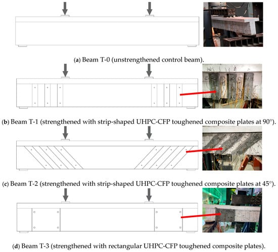
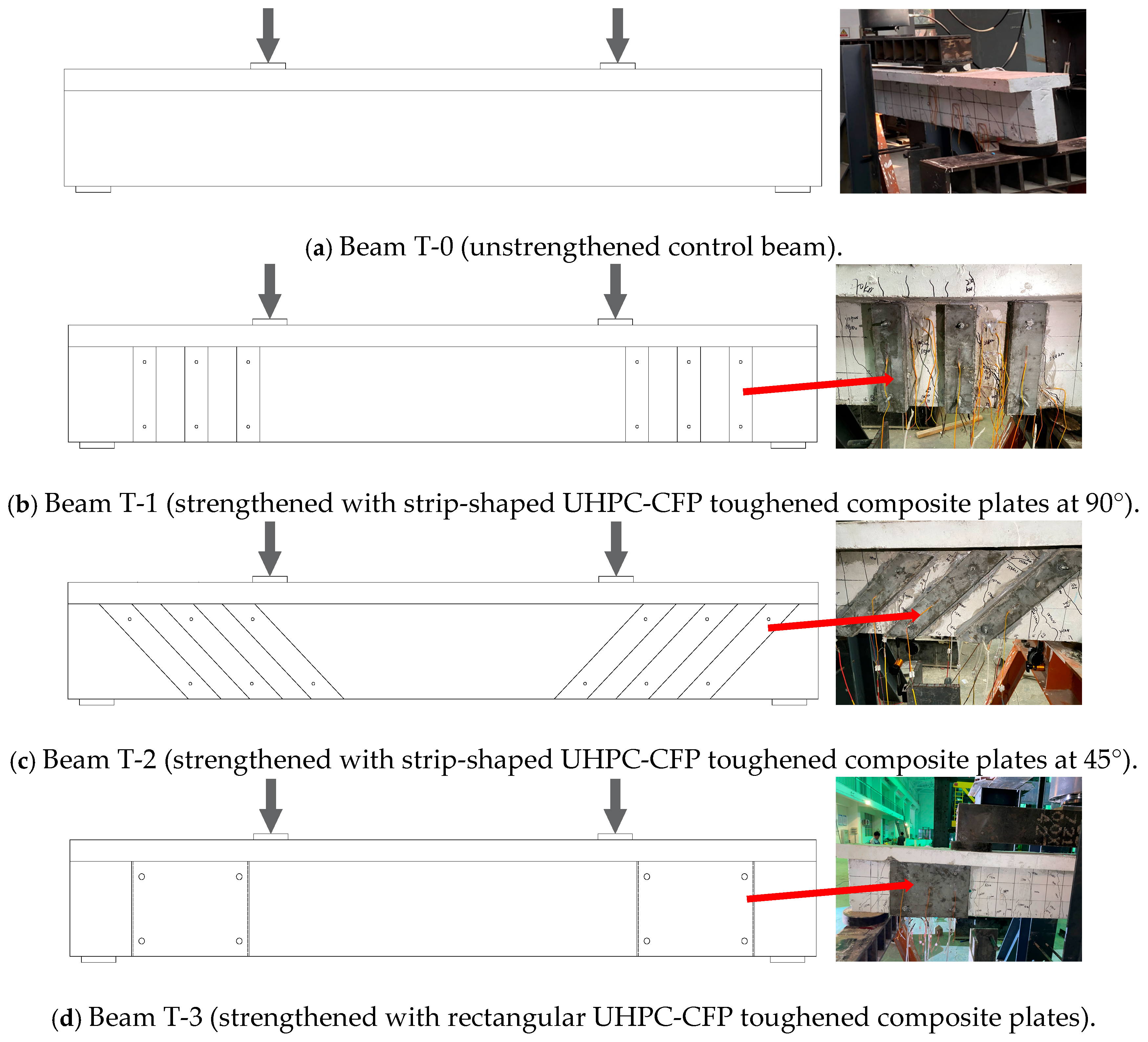
The strengthening methods and dimensions of the test beams are shown in Figure 3 and Table 6. Among them, Beam T-0 was the unstrengthened control beam; Beam T-1 was strengthened with strip-shaped UHPC-CFP toughened composite plates at a 90° angle; Beam T-2 was strengthened with strip-shaped UHPC-CFP toughened composite plates at a 45° angle; and Beam T-3 was strengthened with rectangular UHPC-CFP toughened composite plates.
Figure 3.
Schematic diagram of test beam strengthening methods.
Table 6.
Strengthening methods of test beams.
2.3. Strengthening Process
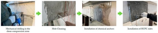
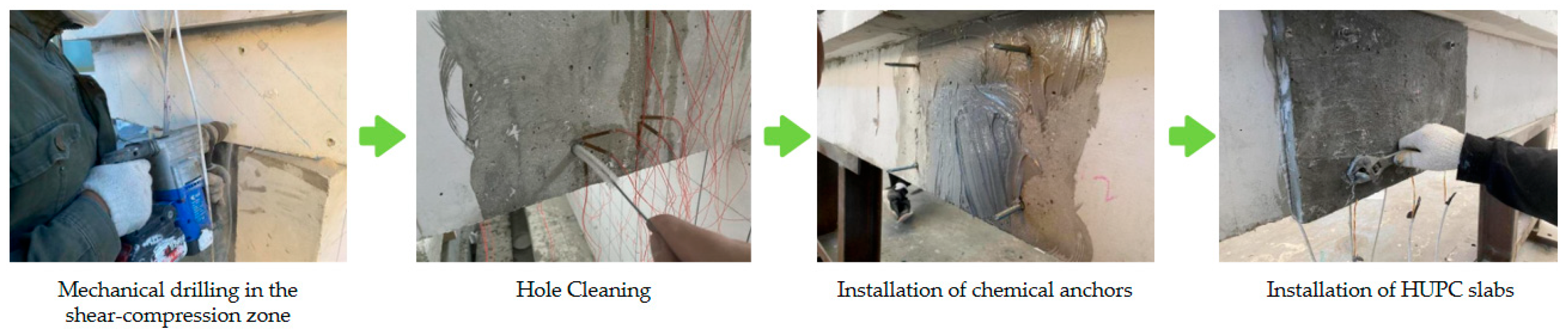
The shear span-to-depth ratio (a/d) of the test beam is designed as 1.8, which falls within the typical range for shear-controlled failure. Meanwhile, sufficient longitudinal tensile reinforcement is arranged in the beam so that the flexural capacity of the section is significantly higher than the shear capacity. To ensure that the precast UHPC plates were tightly attached to the shear-compression zones of the RC-T beams, a “chemical + mechanical” anchorage method was adopted in this experiment, specifically anchoring via structural adhesive bonding and chemical bolts (Jiagu Boshi Construction Technology Co., Ltd., Shanghai, China). First, the positions on the strengthening layer of the shear-compression zones where holes for chemical bolts were required were marked, followed by drilling in sequence. Since there were some uneven areas on the side surfaces of the RC-T beams, a hand-held grinder was used to level these irregular areas. This ensured that the beam surfaces could be tightly attached to the precast UHPC plates, thereby achieving a favorable strengthening effect. Subsequently, a chemical capsule was inserted into the pre-drilled hole in the shear-compression strengthening zone of the RC-T beam. A hand electric drill was used to drive the anchor bolt to the bottom of the hole. After the chemical anchor was fully cured, the structural adhesive, which had been adequately mixed, was uniformly applied to the strengthening zone using a trowel. The structural adhesive employed in this study was Sika Sikadur-31STP (Sika Co., Ltd., Suzhou, China), a trowel-grade structural bonding adhesive for steel. Finally, the UHPC panel was installed and tapped with a rubber mallet to ensure tight contact between the precast UHPC panel and the beam body. Washers and nuts were then fitted onto the 8.8-grade M8 chemical anchor bolts (tightening torque = 22–25 N·m) and tightened with a wrench until the structural adhesive was squeezed out from the contact interface between the edge of the precast UHPC panel and the RC-T beam, thereby ensuring tight and uniform distribution of the adhesive over the entire contact surface. The strengthening process is shown in Figure 4.
Figure 4.
Drilling and surface treatment of strengthened zones in RC-T beams.
2.4. Loading and Measuring Point Schemes
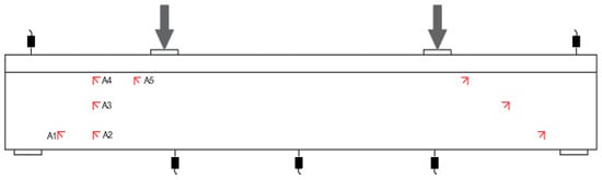
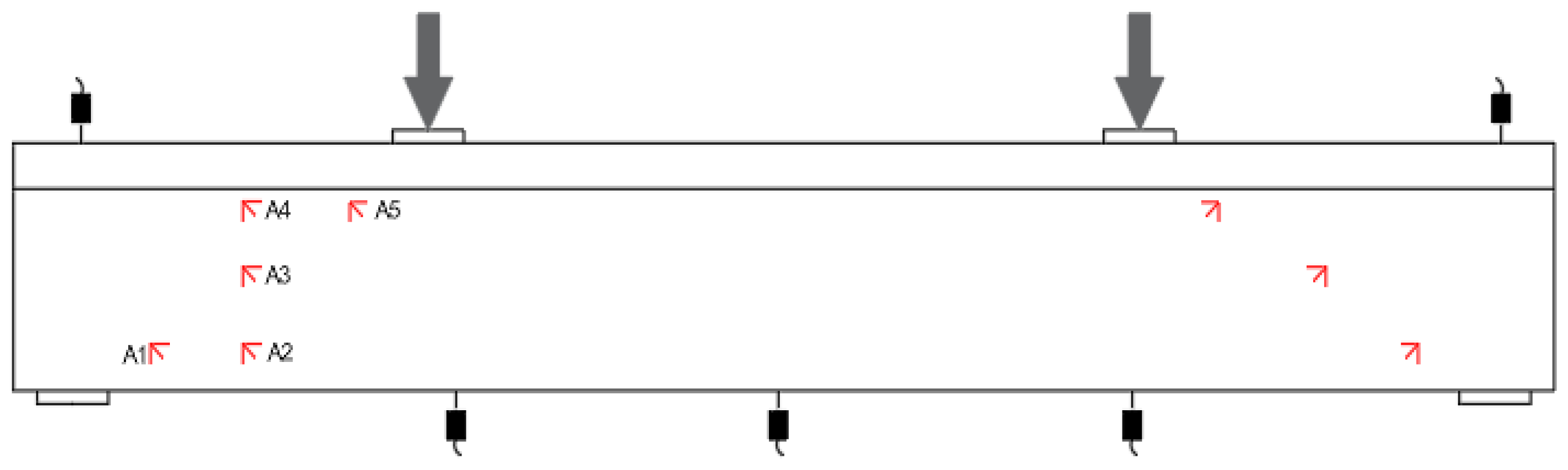
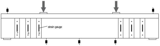
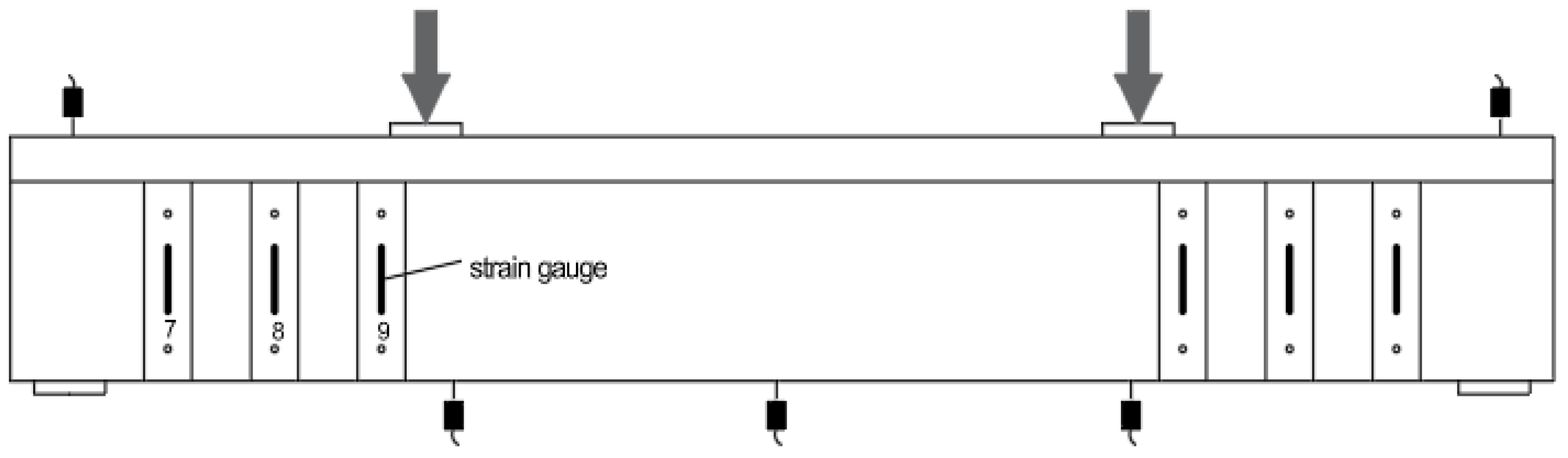
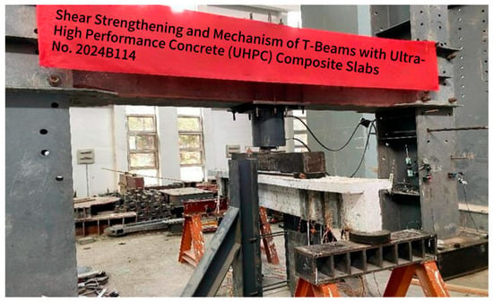
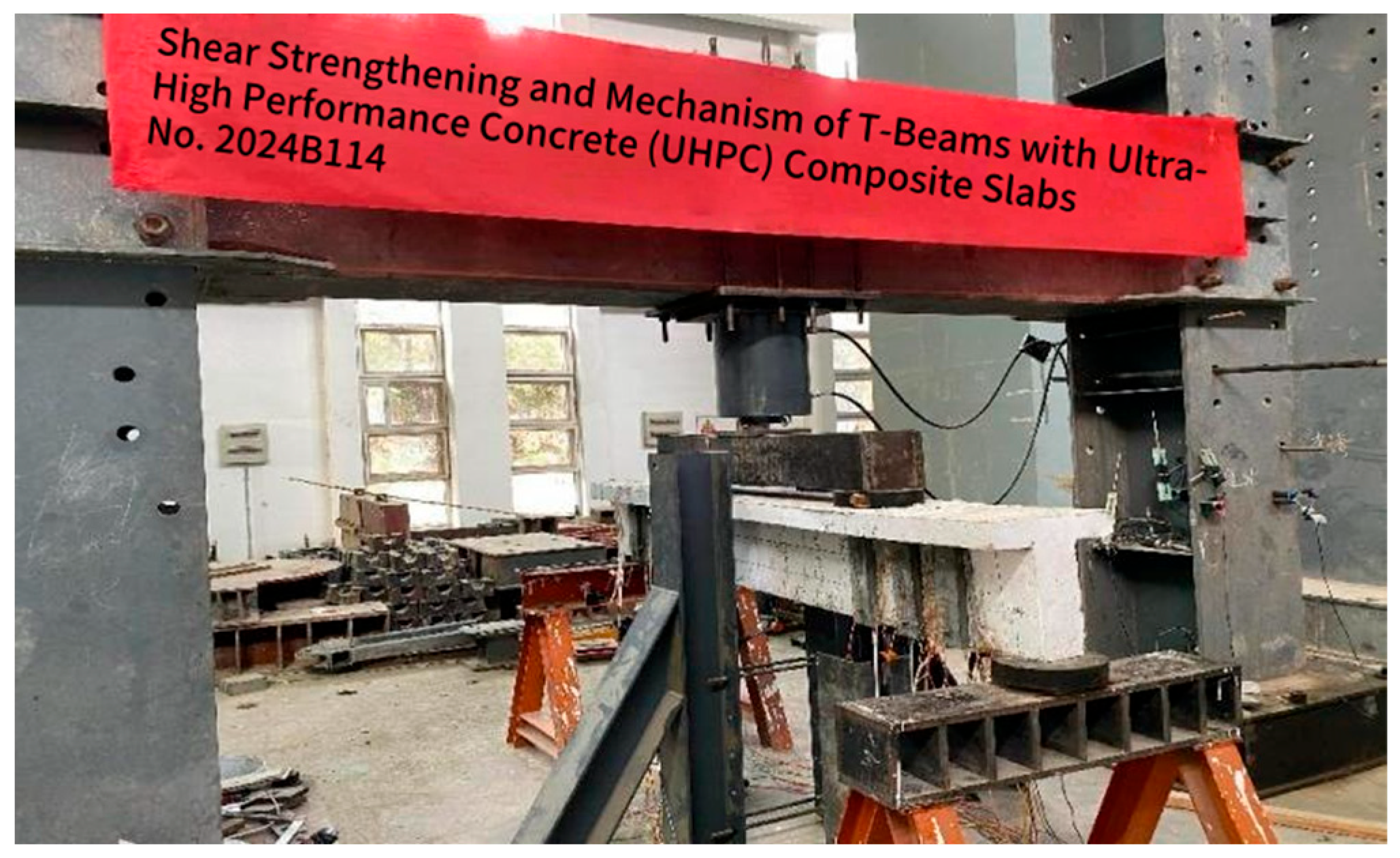
Strain measuring points were arranged on the surfaces of concrete, UHPC, and carbon fiber plates in the flexural-shear zones of the test beams to comparatively analyze the stress changes in the beams and strengthening components during loading. To more clearly reflect the displacement changes in the key sections of the test beams under various load levels, deformation measuring points were installed at the bottom supports, quarter-span, and mid-span of the test beams. A total of five deformation measuring points were set for each test beam. Taking Beams T-0 and T-1 as examples, the layouts of strain and deformation measuring points are shown in Figure 5 and Figure 6, and photos of the loading site are presented in Figure 7.
Figure 5.
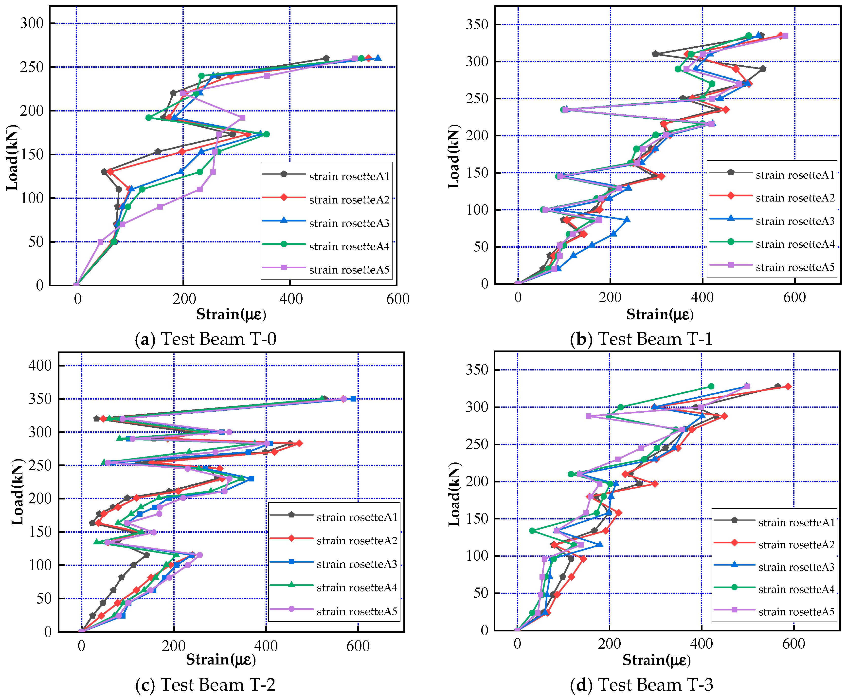
Concrete strain and deformation measuring points of Beam T-0. Note: The “red arrows” in the figure denote strain rosettes, while A1, A2, A3, A4 and A5 correspond to the measuring points shown in Figure 9.
Figure 6.
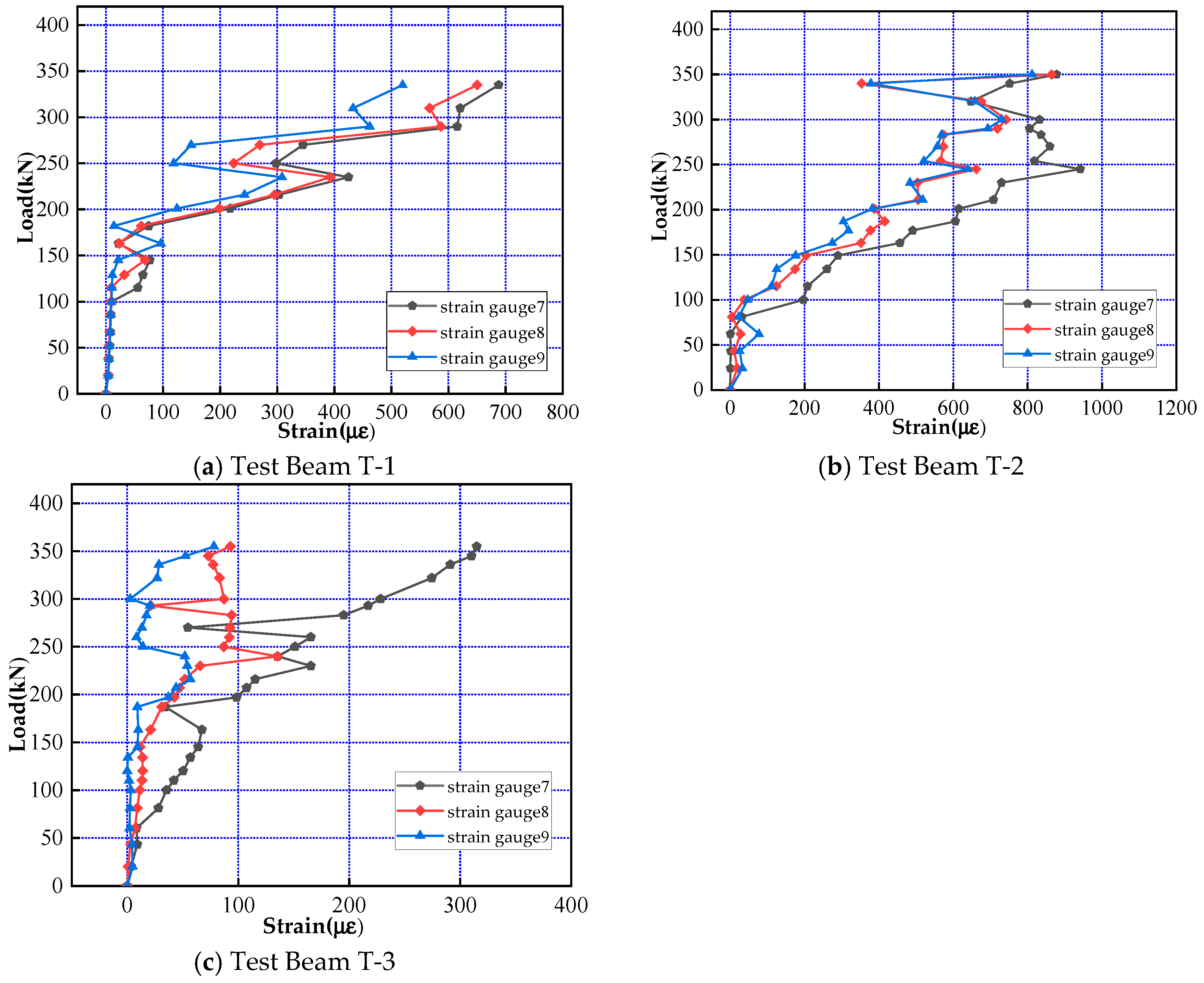
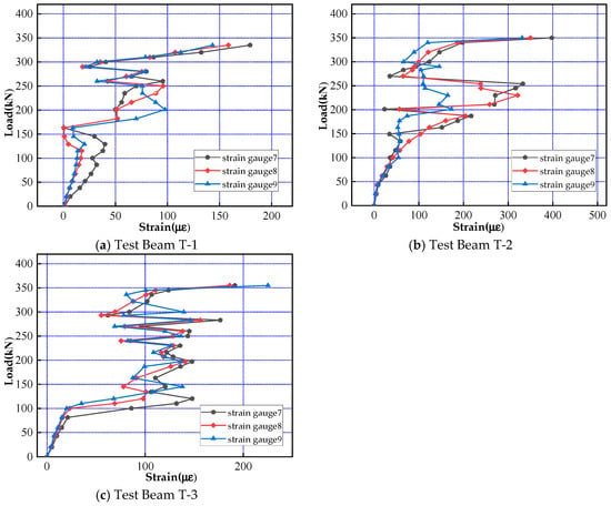
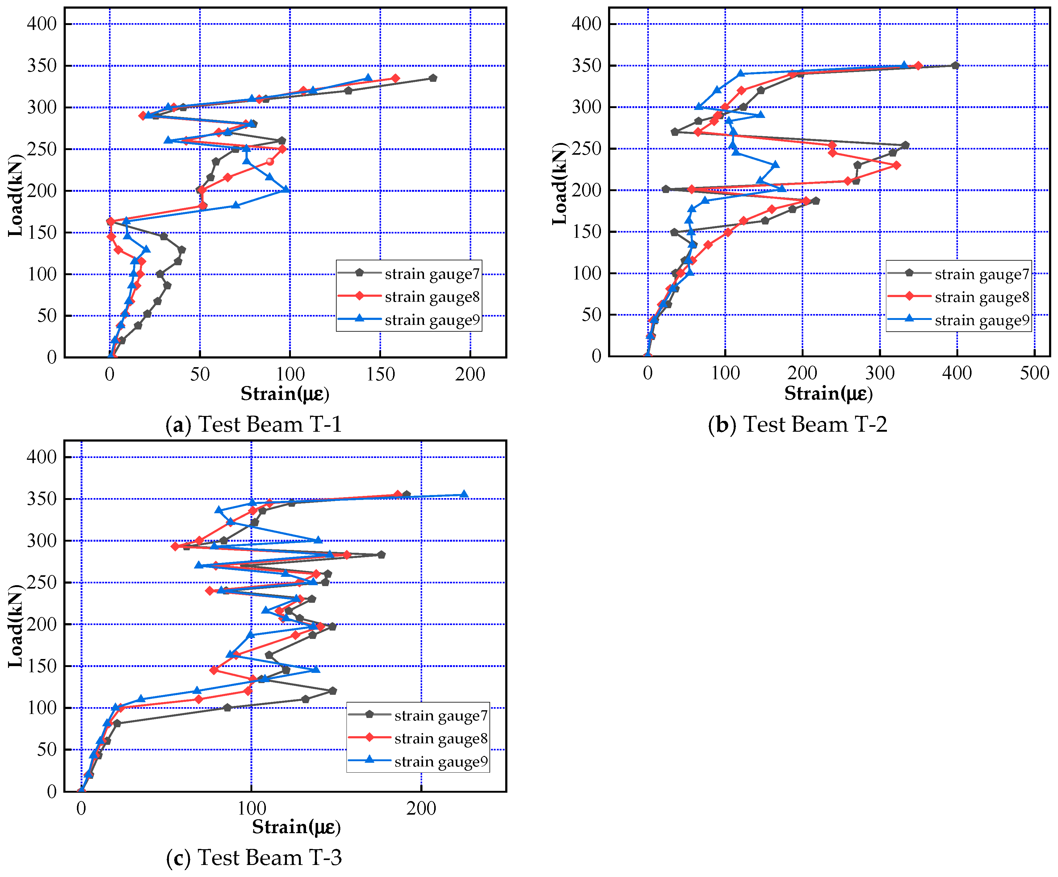
Carbon fiber plate (CFP) strain and deformation measuring points of Beam T-2. Note: The labels 7, 8 and 9 in the figure represent three strain gauges, which correspond to the measuring points presented in Figures 10 and 11.
Figure 7.
Loading site photos.
3. Test Results and Analysis
3.1. Failure Modes
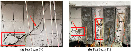
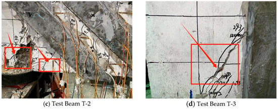
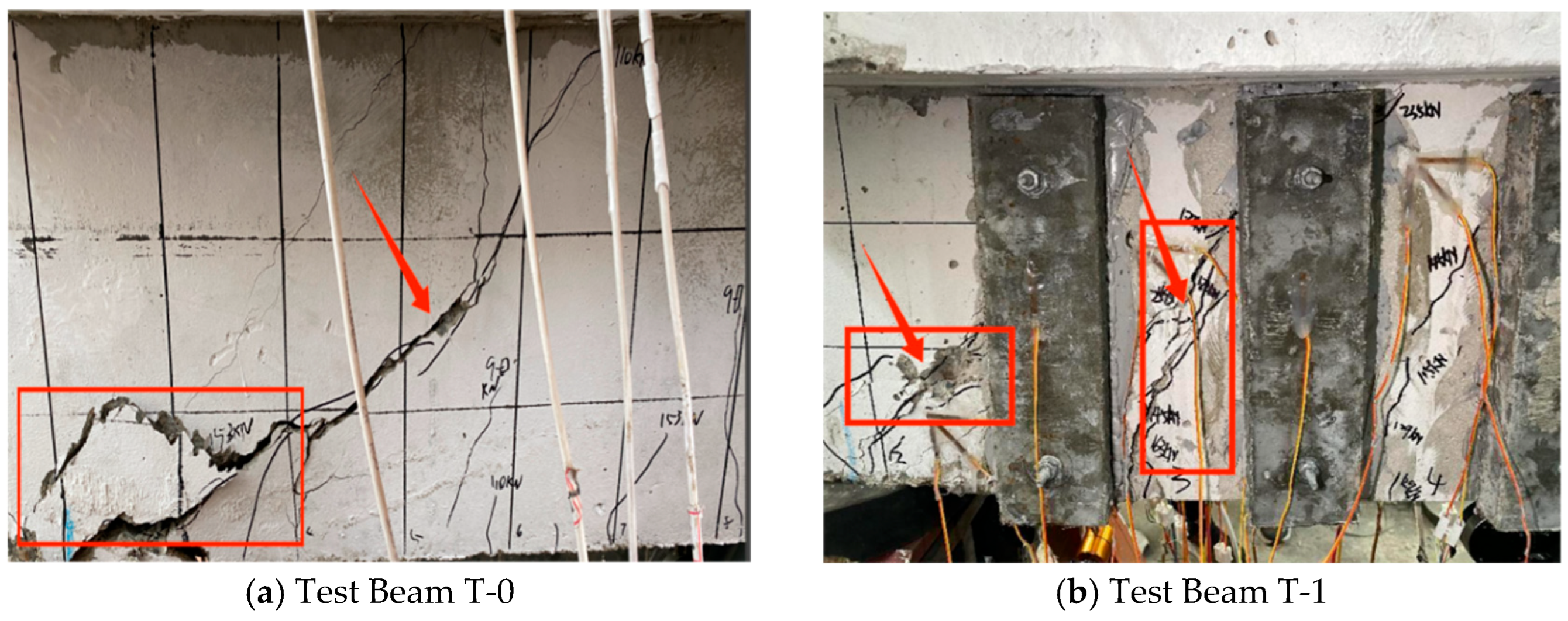
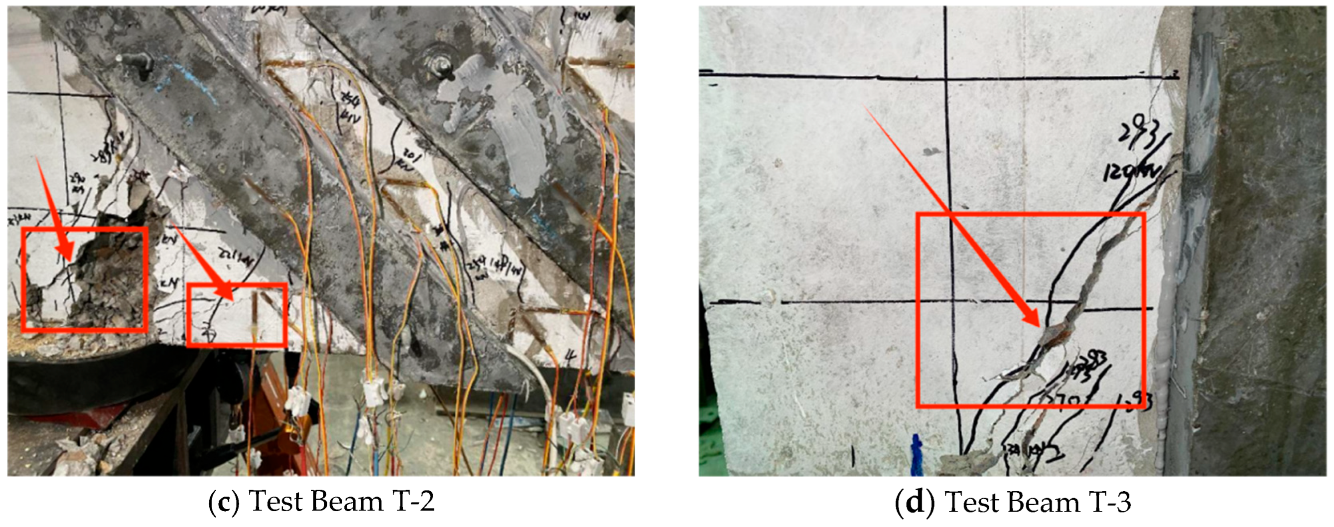
The failure modes of the shear zones of the test beams are shown in Figure 8. Analysis of Figure 8 reveals the following: (1) All test beams exhibited obvious shear failure. At the later stage of the test, cracks appeared in the compressed flanges, indicating that the flanges of the T-beams also participated in bearing part of the load. (2) For the unstrengthened control Beam T-0, vertical flexural cracks first appeared in the pure bending region at the early loading stage and developed relatively slowly throughout the test. At the middle loading stage, vertical cracks emerged in the shear span region and rapidly propagated from the supports toward the loading points. Meanwhile, the width of inclined cracks increased more quickly than that of vertical flexural cracks, yet no failure occurred because the stirrups maintained the load-bearing capacity and retarded the widening of inclined cracks. At the late loading stage, concrete crushing was observed in the shear-compression zone, owing to the tensile failure of concrete on both sides of the main inclined crack reaching its ultimate tensile strain. (3) Compared with the unstrengthened beam, only a small number of vertical flexural cracks appeared in the pure bending region of Beam T-1 at the early loading stage. At the middle loading stage, inclined cracks formed in the concrete areas between the adjacent UHPC–carbon fiber composite plate (UHPC-CFP) striped strengthening layers, as well as near the supports. Restrained by the UHPC-CFP striped strengthening layers, which exerted a “stirrup-like” confining effect, the propagation path of the main inclined crack was altered: instead of extending from the supports toward the loading points, the cracks propagated from the bottom of the web (near the supports and between the strengthening strips) toward the top of the loading point within a 10 cm range, with a changed inclination angle. Several wide inclined cracks appeared in the concrete between the UHPC-CFP toughened composite strips of Beam T-1, whereas fewer inclined cracks were observed in the corresponding regions of Beam T-2. (4) The failure characteristics and crack propagation path of Beam T-2 were similar to those of Beam T-1. However, the UHPC-CFP strengthening layers of Beam T-2 were arranged at an inclination angle of 45°, which was nearly perpendicular to the main inclined cracks propagating from the supports to the loading points in the shear span. Consequently, the UHPC-CFP layers more effectively suppressed the propagation and widening of the main inclined cracks. At the middle-to-late loading stage, inclined cracks appeared in the UHPC-CFP strengthening layers near the supports, and inclined cracks toward the loading points also formed in the compression flange, indicating that both the UHPC-CFP layers and the compression flange contributed to the improvement in the inclined section’s shear capacity. At the late loading stage, minor micro-cracks occurred in the UHPC-CFP toughened composite strips of Beams T-1 and T-2, but the bonding between the composite strips and the original concrete remained firm. (5) During the loading process of Beam T-3, the diagonal cracks propagated from the supports to the strengthened plates and then stopped extending. Until the end of loading, no cracking occurred in the UHPC-CFP toughened composite plates.
Figure 8.
Failure modes of test beams. Note: The anchorage details of all beams are reliable and the anchorage performance meets the mechanical requirements. The observed differences in damage and failure modes among the beams are mainly attributed to the different geometrical configurations of the UHPC-CFP strengthening plates rather than the difference in anchorage effect.
3.2. Main Characteristic Loads
A comparison of the characteristic loads and deflections of each test beam is presented in Table 7, where Psh denotes the shear capacity, corresponding to the load at which the diagonal crack width reaches 1.5 mm. A crack width of 1.5 mm is a widely accepted limit for inclined shear cracks in reinforced concrete beams, as specified in the Standard for Test Methods of Concrete Structures (GB/T 50152-2012) [37]. This value is also commonly adopted in similar experimental studies. It can be seen from Table 7 that all load indices of the strengthened beams are increased in comparison with the unstrengthened one, with the ultimate bearing capacity improved by 28.8%, 34.6% and 36.5%, respectively. As shown in Table 7, compared with the unstrengthened beam, all strengthened beams exhibited an improvement in shear capacity. Specifically, the shear capacity of Beams T-1 and T-2 increased by 27.0% and 40.5%, respectively. Beam T-3 achieved the maximum increase in shear capacity (43.2%), but it also had the largest mid-span deflection. Analysis indicates that this phenomenon occurred because the strengthening range of the test beams was limited to the region from the supports to the quarter-span of the beams. Although this strengthening scheme improved the shear capacity, it did not significantly enhance the flexural capacity, leading to a continuous increase in mid-span deflection. Given that Beam T-3 required the largest amount of strengthening material, the strengthening scheme applied to Beam T-2 was determined to be the optimal one.
Table 7.
Comparison of characteristic loads and deflections of test beams.
3.3. Strain Results
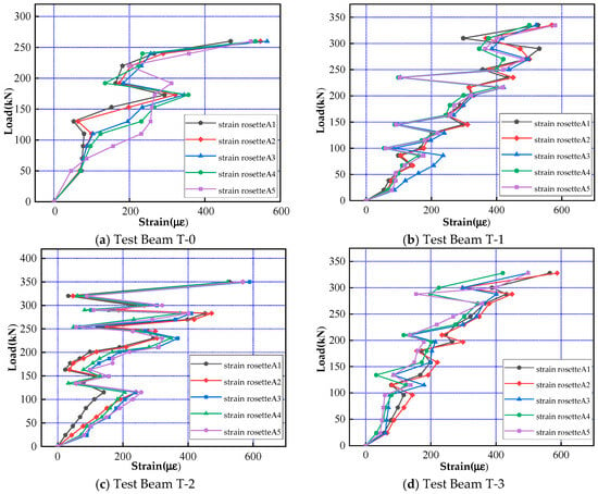
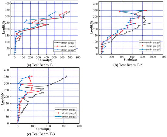
The load–strain curves of concrete, UHPC-CFP toughened composite plates, and carbon fiber plates are shown in Figure 9, Figure 10 and Figure 11. As indicated in Figure 9, after diagonal cracks appeared in the shear-compression zones of the beams, the shear force borne by the concrete was gradually transferred to the steel bars and the strengthening layers. This transition process caused a redistribution of strain, which further resulted in an obvious inflection point in the load–strain curves. From Figure 10, it can be observed that the load–strain curves of the UHPC-CFP toughened composite plates for Beams T-1 and T-2 exhibited a similar development trend, with significant fluctuations in strain values during the loading process. In contrast, the strain values of Beam T-3 showed smaller fluctuations. This phenomenon occurred because the strengthening area of the rectangular plates was relatively large, preventing the UHPC-CFP toughened composite plates from fully exerting their effectiveness. As shown in Figure 11, the strain of the embedded carbon fiber strips fluctuated slightly in the early stage of loading, but changed significantly when the main diagonal cracks passed through. This confirms that the embedded carbon fiber strips participated in the force-bearing process of the UHPC-CFP toughened composite plates, effectively delaying the propagation of cracks on the surface of the UHPC plates and functioning as the “reinforcing ribs” of the UHPC-CFP toughened composite plates.
Figure 9.
Load–strain curve of concrete.
Figure 10.
Load–strain curve of UHPC composite plates.
Figure 11.
Load–strain curve of carbon fiber plates (CFPs).
4. Finite Element Numerical Simulation
4.1. Model Establishment
The finite element analysis was performed to further validate the accuracy and reliability of the test results, reveal the internal stress distribution, crack propagation and failure mechanism that cannot be directly observed experimentally, and conduct parametric studies to extend the applicability of the experimental findings.
In the finite element analysis (FEA) of the test beam, the model was established using ABAQUS2016 software, and the Newton–Raphson algorithm was adopted for the solver. The parameters defined in the Concrete Damaged Plasticity (CDP) model include the dilation angle φ of the yield surface during the concrete hardening process, the eccentricity ε of the potential function, the ratio of biaxial to uniaxial compressive strength fb0/fc0, the strength ratio along the tension–compression meridian kc, and the viscosity parameter μ. In this study, the values of ε, fb0/fc0, and kc are adopted as 0.1, 1.16, and 0.6667, respectively. At present, there is no unified standard for the value of the dilation angle φ in the CDP model based on studies by scholars worldwide and relevant specifications, and the reasonable range of φ is generally recognized as 30° to 42°. To ensure the accuracy and convergence of the nonlinear model in equilibrium calculations, a reasonable range for the viscosity parameter μ is from 10−3 to 10−6, and the value of μ adopted in this study is 1 × 10⁻⁵. The general parameter values of concrete and UHPC materials in the CDP model are listed in Table 8.
Table 8.
Values of general parameters of CDP model concrete materials.
For the finite element model of the test beam, the longitudinal reinforcement and stirrups were modeled using T3D2 Truss elements with an ideal elastoplastic constitutive model and perfect bond assumption—the steel reinforcement was treated as an elastoplastic material, where the stress remains constant after reaching the yield strength without any increase under continuous loading, and no relative slip was assumed between the steel reinforcement and concrete, with the reinforcement nodes fully coupled to the concrete elements to enforce complete deformation compatibility. The concrete, carbon fiber plates (CFPs), supports, and precast UHPC plates were simulated with C3D8R solid elements (reduced integration with hourglass control). During the entire test, no slipping or debonding occurred between the UHPC-CFP toughened composite plate strengthening layer and the concrete beam. Therefore, a tie constraint was applied between the strengthening layer and the concrete beam to simulate their bonded contact. In addition, the UHPC composite plate was simulated as a single monolithic material block with perfect bonding, assuming no relative slip or debonding between UHPC and CFPs.
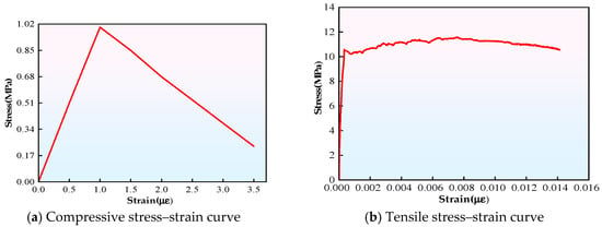
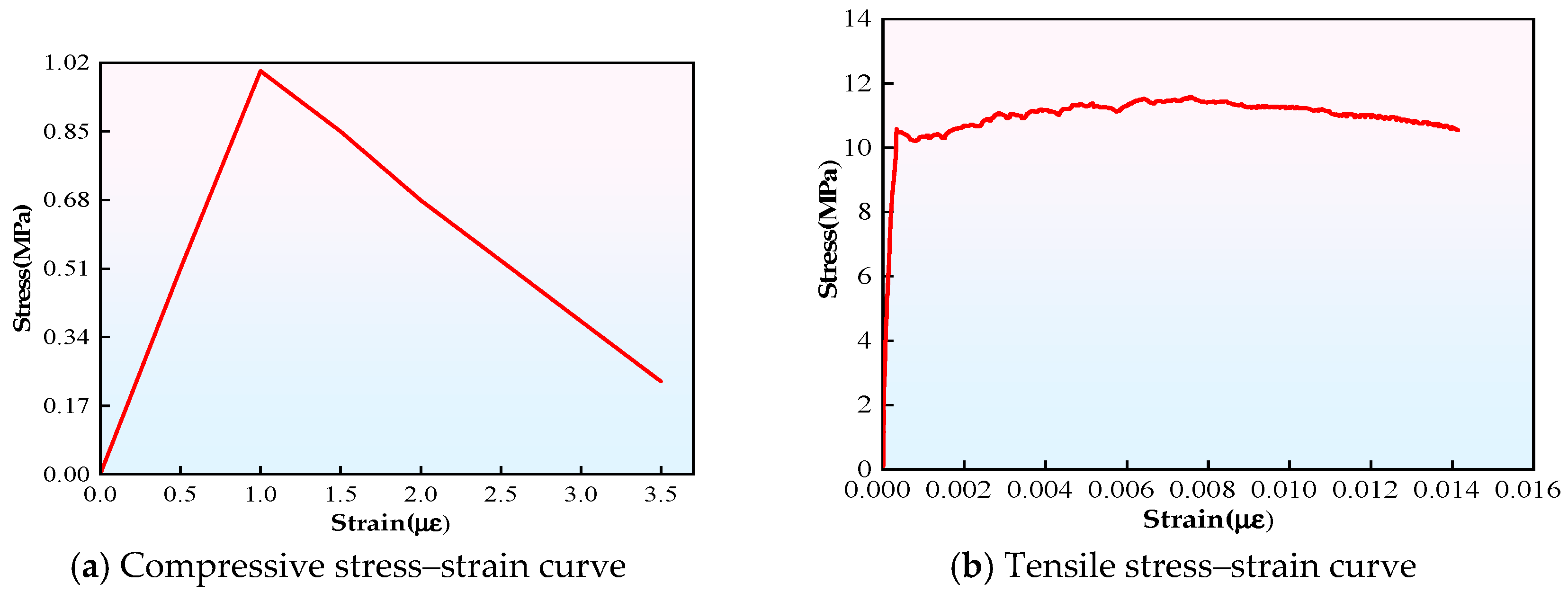
To characterize the compressive constitutive behavior of UHPC, this paper adopts an ascending–descending bilinear constitutive model to fit its compressive stress–strain relationship [38]. The tensile stress–strain curve is fitted according to the UHPC-specific design code issued by the French Association of Civil Engineering (AFGC) and the Technical Studies Service for Roads and Highways (SETRA) [39]. The stress–strain curves of UHPC under compression and tension are shown in Figure 12. The mesh size of the test beam’s finite element model was set to 25 mm.
Figure 12.
UHPC stress–strain curve.
4.2. Model Validation
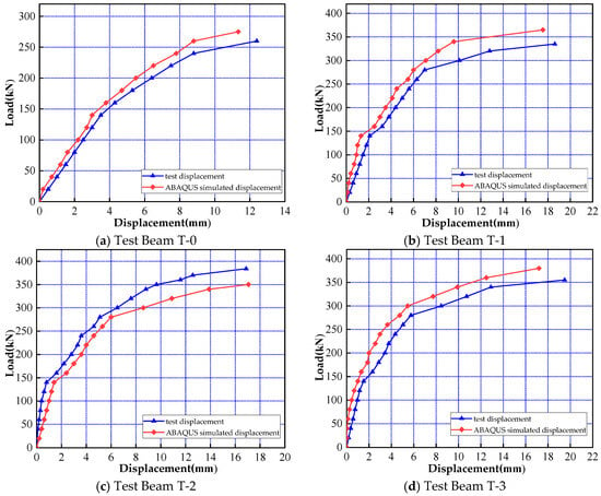
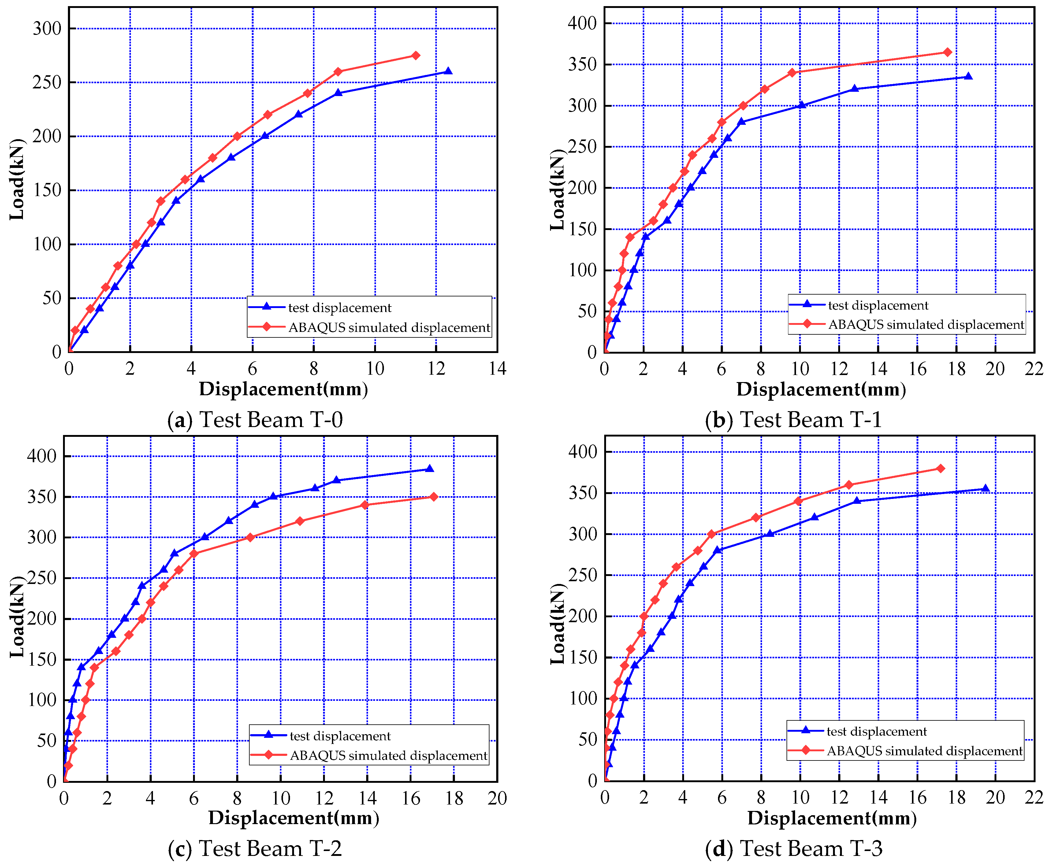
A comparative analysis of the load–displacement curves between the test beams and numerical simulations was conducted, as shown in Figure 13. As indicated in Figure 13, the load–displacement curves of the test beams and numerical simulations exhibited a similar overall trend, and the results of the finite element numerical simulation were in good agreement with the test results. For Beams T-0 to T-3, the errors of the first cracking load were 7.7%, 3.1%, 4.1%, and 4.2%, respectively, while the errors of the failure load were 7.7%, 8.4%, 9.7%, and 7.9%, respectively. Based on the comparative verification results, the established finite element model exhibits high overall reliability and can accurately characterize the mechanical behavior and failure characteristics of UHPC-CFP strengthened RC beams. It can be used as a reliable tool for parametric analysis and research.
Figure 13.
Load–displacement curve.
4.3. Analysis Results
- (1)
- Concrete Crack Distribution
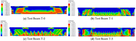
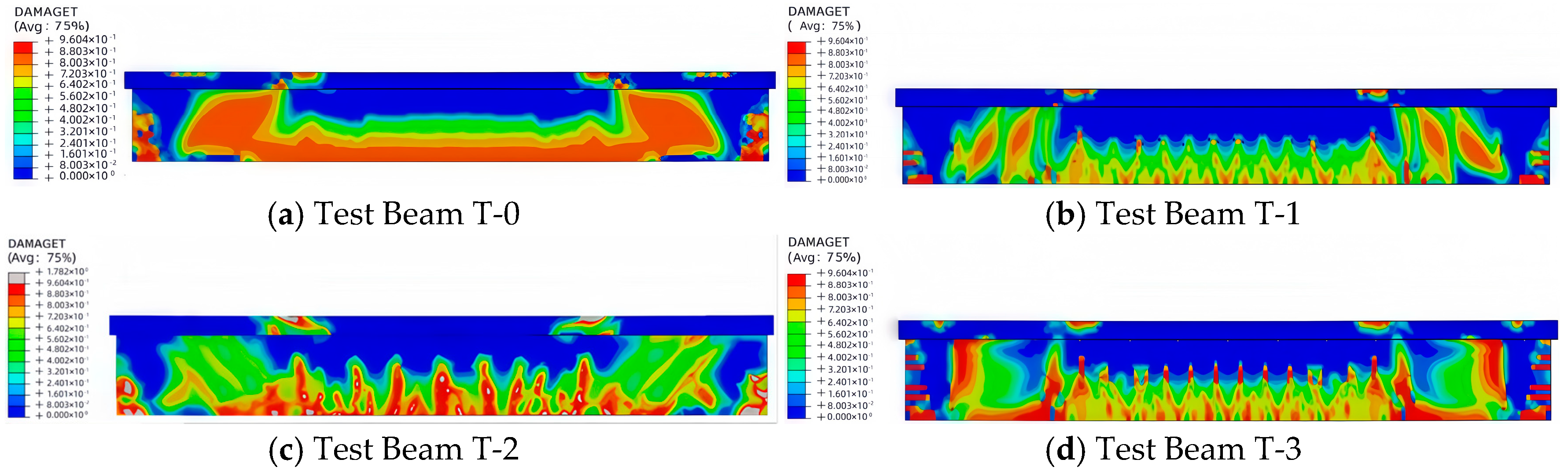
It can be seen from the numerical simulation diagrams of crack distribution in the test beams at the middle loading stage (Figure 14) that obvious shear cracks appear in the webs of all test beams. After the occurrence of inclined cracks, they rapidly propagate from the supports toward the loading points. For the T-0 beam, the cracks cover a relatively large area and are densely distributed, but the beam does not fail, which is attributed to the stirrups that maintain the bearing capacity and retard the widening of inclined cracks. Compared with the T-0 beam, the T-1 to T-3 beams show more dispersed crack distributions, indicating that the UHPC-CFP toughened composite plates used in the three strengthening schemes all exert a certain shear strengthening effect. As revealed by the comparative analysis between Figure 15b and Figure 8b, several wide inclined cracks appear between the UHPC strips of the T-1 beam in both the numerical simulation and the field test. The T-2 beam has fewer inclined cracks between the UHPC strips, which is basically consistent with the field failure mode of the test beam shown in Figure 8c. At the late loading stage, relatively fine cracks appear between the UHPC strips of both test beams. During the loading of the T-3 beam, the inclined cracks stop propagating after extending from the support to the strengthened plate, and the loading terminates when large inclined cracks form. No cracking occurs in the UHPC-CFP toughened composite plate, which is also basically consistent with the field test phenomenon shown in Figure 8d.
Figure 14.
Crack distribution.
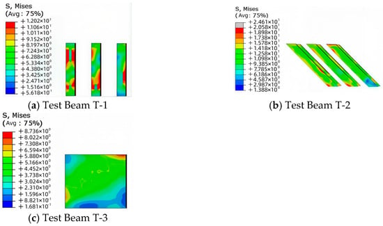
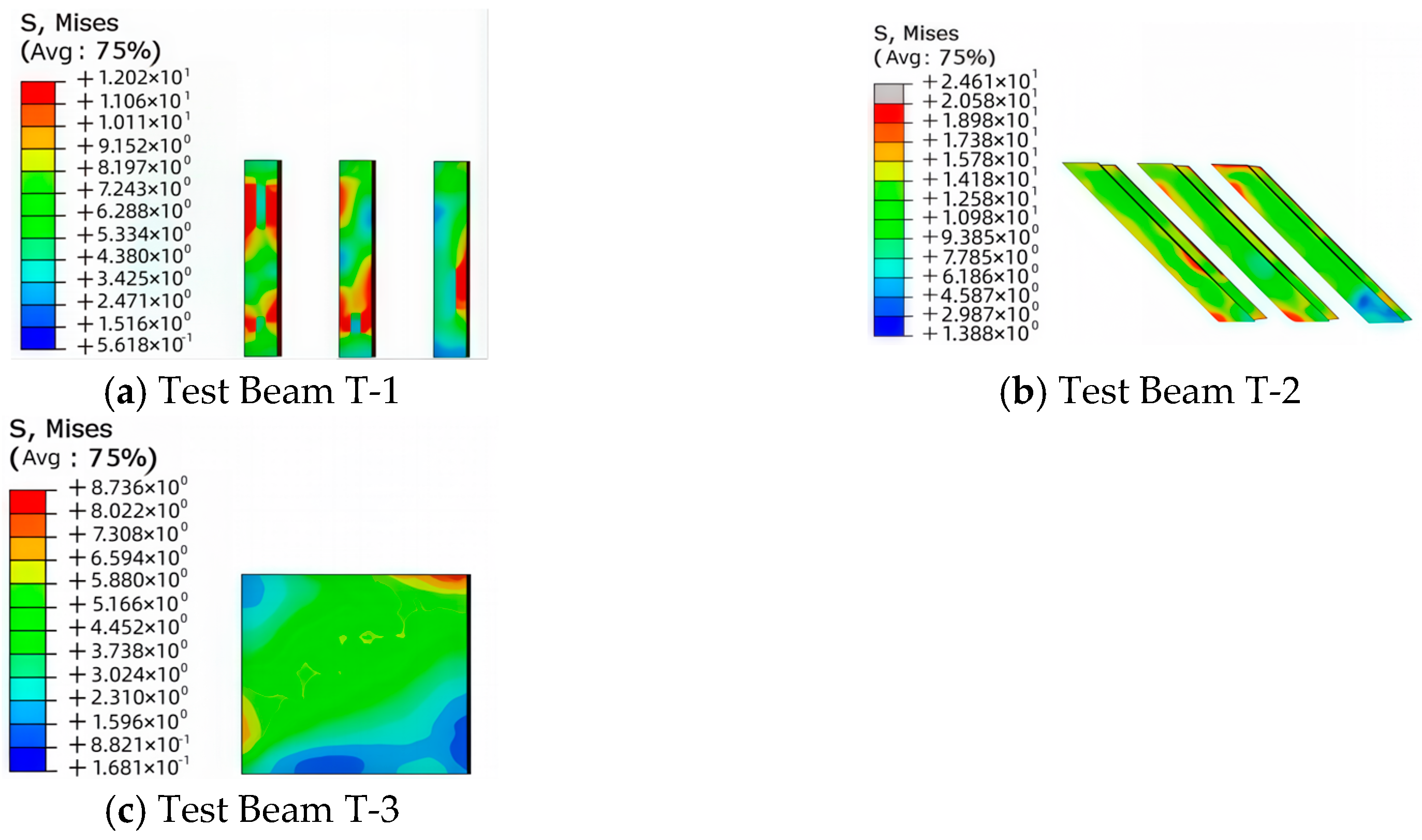
Figure 15.
Stress distribution of UHPC-CFP toughened composite plates.
- (2)
- Stress of UHPC-CFP Toughened Composite Plates
According to the stress distribution of the UHPC-strengthened members in Figure 16, the stress level of the UHPC-CFP toughened composite plates shows significant differences under different reinforcement schemes, indicating that the composite plates contribute to shear resistance to varying degrees under each working condition. Specifically, the maximum and average von Mises stresses of the UHPC composite plate are 12.02 MPa and 9.015 MPa for Beam T-1, and the corresponding values are 20.5 MPa and 15.375 MPa for Beam T-2. The maximum and average von Mises stresses of the UHPC composite plate for Beam T-3 are only 8.736 MPa and 6.552 MPa, respectively. The stress level of the UHPC strip composite plates in Beams T-1 and T-2 is significantly higher than that of the UHPC rectangular composite plate in Beam T-3, which demonstrates that the strip reinforcement form can more fully mobilize the mechanical properties of the UHPC-CFP material and allow it to play a greater role in the shear resistance process.
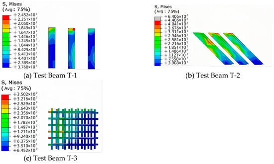
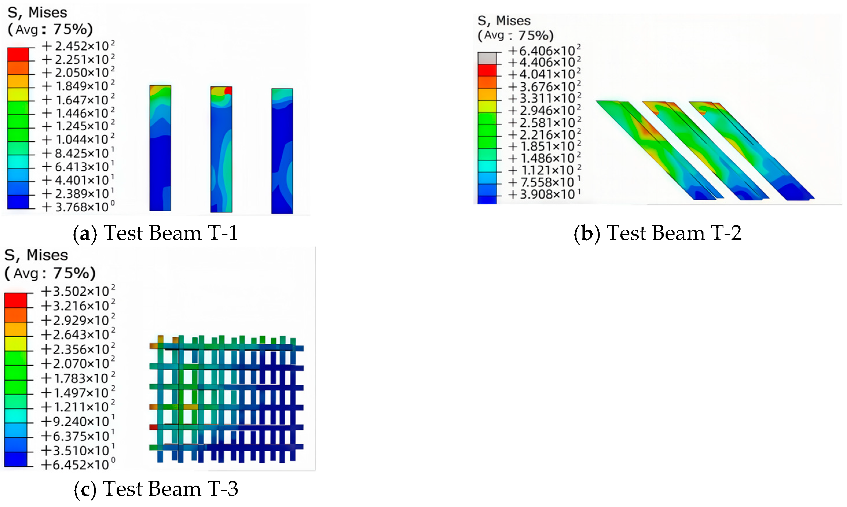
Figure 16.
Stress distribution of embedded carbon fiber plates.
- (3)
- Stress of Embedded Carbon Fiber Plates
It can be seen from the stress distribution of the built-in carbon fiber plates (CFP) in Figure 16 that the stress of the built-in CFP varies obviously under all three strengthening schemes. This proves that the built-in CFP participates in the load bearing of the UHPC-CFP toughened composite plates and acts as a reinforcing rib, which is basically consistent with the field strain data of the CFP shown in Figure 11. The stress of the strip-strengthened CFP in the T-1 and T-2 beams is relatively high, while the stress of the grid-shaped CFP in the rectangular-strengthened T-3 beam is relatively low. This is consistent with the stress distribution of the UHPC-CFP toughened composite plates under the three strengthening schemes.
5. Shear Resistance Mechanism and Calculation Formula of Strengthened Beams
5.1. Shear Resistance Mechanism of Strengthened Beams
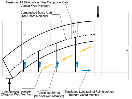
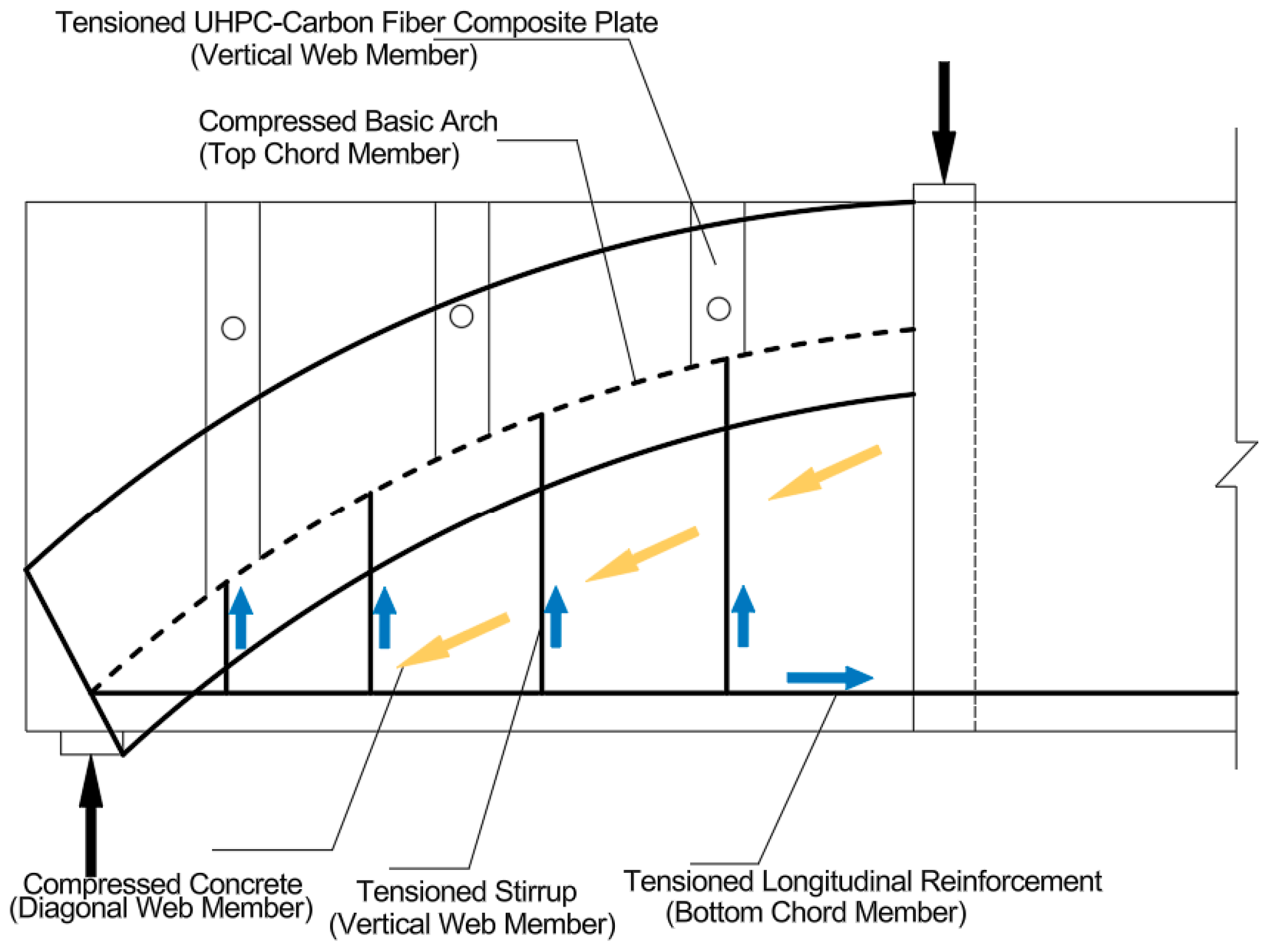
Liu, L.X. et al. [40] investigated the shear resistance mechanism of members with web reinforcement, and proposed that the shear capacity of such members is jointly composed of truss action and arch action. In this mechanism, the concrete in the shear-compression zone is regarded as the diagonal web members of the truss–arch model, while the longitudinal tensile reinforcement and stirrups correspond to the tension members and compression members in the truss–arch model, respectively. Corresponding to the results of this study and based on numerical simulation analysis, it is considered that the truss–arch model theory is also applicable to the shear resistance mechanism of beams strengthened with composite plates, as shown in Figure 17. In Figure 17, the basic arch body and the longitudinal tensile reinforcement work synergistically to form an arch-shaped structural system. Specifically, the concrete in the shear-compression zone, which is compressed diagonally along the cracks, acts as the compressed diagonal web members in the truss model; the stirrups and UHPC-CFP toughened composite plates serve as the tensile vertical web members in the truss model; and the carbon fiber plates function as the reinforcing ribs for the UHPC-CFP toughened composite plates.
Figure 17.
Truss–arch model for strip-shaped strengthening with UHPC-CFP toughened composite plates.
5.2. Proposed Design Formula for Shear Capacity of Strengthened Beams
The shear capacity of the strengthened beam is mainly provided by plain concrete (C), stirrups (SV), UHPC, and carbon-fiber-reinforced polymer (CFRP) plates, as shown in Equation (1).
where: Vc—shear resistance of concrete in the RC T-beam before strengthening; Vsv—shear resistance of stirrups in the RC T-beam before strengthening; VUHPC—shear resistance provided by the UHPC precast slab strengthening; VCFRP—shear resistance provided by the CFRP laminate strengthening.
The calculation formulas for the shear capacity of ordinary concrete and stirrups are adopted from the Code for Design of Concrete Structures (GB 50010-2010) [41]. The difference is that this paper also incorporates the contribution of the compression flange of concrete T-beams to the shear capacity, as specified in the Specifications for Design of Highway Reinforced Concrete and Prestressed Concrete Bridges and Culverts (JTG 3362-2018) [42], and the established formula is shown in Equation (2).
where is the influence coefficient of the compressed flange, taking a value of 1.1 for T-beams. ft—axial tensile strength of concrete; b, h0—web width and effective depth, respectively; s, Asv, fyv—stirrup spacing, cross-sectional area of stirrups, and design value of tensile strength of stirrups, respectively.
For the contribution of UHPC to shear capacity, reference is made to the Swiss code UHPFRC: Materials, Design and Application (SIA 2052-2016). The code proposes to treat steel fibers and the UHPC matrix as an integral material, and simultaneously considers the influence of the principal stress direction and the relationship of tensile strength, thereby establishing the calculation formula for the shear capacity of UHPC, as shown in Equation (3).
where is the strength utilization coefficient of the UHPC strengthening layer. According to the results of this study, although the UHPC strengthening layer eventually cracked, no debonding was observed throughout the test; thus, a value of 1.0 is recommended. is the angle between the UHPC strengthening layer and the longitudinal axis of the beam. fUted and fUtud represent the elastic tensile strength and ultimate tensile strength of UHPC, respectively.
The shear capacity of CFRP laminates is calculated using the formulas specified in the Technical Specification for Concrete Structures Strengthened with Carbon Fiber Reinforced Polymer Composites (T/CECS 146-2022) [43], as shown in Equations (4)–(6).
where: τb—design value of bond strength between CFRP laminate and concrete; Kcf—shear debonding coefficient; —strengthening configuration coefficient, taken as 1.0 for side strengthening; σcf —effective stress of CFRP laminate; Scf—spacing of strip-type CFRP strengthening, taken as 0 for continuous axial bonding; tcf—thickness of CFRP laminate; ωcf—width of CFRP laminate; hcf—effective bonding height of CFRP laminate; β—angle between the bonding direction of CFRP laminate and the longitudinal axis of the beam; ft—design value of concrete tensile strength.
Substituting the above Equations (2)–(6) into Equation (1), the proposed Formula (7) for calculating the shear capacity of RC T-beams strengthened with UHPC–carbon fiber composite strips can be obtained as follows:
In the proposed calculation formula, the influences of the compression flange of RC T-beams and the strengthening angle on the shear performance are considered. In addition, the key parameter, i.e., the strength utilization coefficient of each strengthening layer material, is incorporated into the formula. On the whole, the formula is designed to be conservative to ensure structural safety while maintaining its simplicity, which makes the calculation process relatively convenient and easy to implement.
Based on the proposed design formula for the shear capacity of T-beams strengthened with UHPC-CFP toughened composite plates in this study, verification calculations were conducted for Beams T-1 and T-2, respectively, and the result comparison is presented in Table 9. The results show that the average value of the ratio between the calculated shear capacity and the test shear capacity of Beams T-1 and T-2 is 0.87. The difference between the shear capacity obtained by the proposed calculation formula and that from the model test is relatively small, indicating that the calculation results are reliable.
Table 9.
Comparison of shear capacity verification results.
6. Conclusions
Aiming at the common problem of insufficient shear capacity in existing highway RC T-beams, this paper proposes three strengthening schemes using UHPC–carbon-fiber-reinforced polymer (CFRP) composite slabs. Laboratory load tests were carried out, and a comparative analysis was conducted with the UHPC rectangular strengthening scheme and an unstrengthened control beam. This study focuses on the failure characteristics during the entire shear failure process, the mechanical responses, and the strengthening performance of each scheme for RC T-beams. Corresponding beam models were established and verified using the finite element numerical simulation software ABAQUS, which further revealed the failure characteristics of the beam, the role of each strengthening layer component, and the failure mechanism. Based on current codes and test data, a proposed formula for calculating the shear capacity of RC T-beams strengthened with strip-type UHPC-CFRP composite slabs is presented. The main conclusions are as follows:
- (1)
- After the appearance of diagonal cracks in Beam T-0 (unstrengthened), the cracks propagated rapidly from the supports to the loading points. For Beam T-1, multiple diagonal cracks with large widths occurred between the strips of the UHPC-CFP toughened composite plates, while fewer diagonal cracks were observed between the composite plate strips of Beam T-2. In Beam T-3, the diagonal cracks propagated from the supports to the strengthened plates and then ceased to extend. During the loading process, fine cracks appeared in the UHPC-CFP toughened composite strips of Beams T-1 and T-2, whereas no cracking was found in the UHPC plates of Beam T-3.
- (2)
- Compared with the unstrengthened beam (T-0), all strengthened beams exhibited improved shear capacity. Specifically, the shear capacity of Beams T-1 and T-2 increased by 27.0% and 40.5%, respectively. Beam T-3 achieved the maximum increase in ultimate capacity (43.2%) but also showed the largest mid-span deflection. This is because the strengthening range was limited to the region from the beam supports to the quarter-span points: although this range enhanced the shear capacity, the flexural capacity did not improve significantly. Considering that Beam T-3 required the largest amount of strengthening material, Beam T-2’s strengthening scheme was determined to be the optimal one.
- (3)
- The UHPC strip-shaped composite plates in Beams T-1 and T-2 exhibited relatively high stress, while the UHPC rectangular composite plate in Beam T-3 showed relatively low stress. This indicates that the strip-shaped strengthening form enables more efficient utilization of material properties. Under all three strengthening schemes, the stress of the embedded carbon fiber plates changed significantly, which confirms that the embedded carbon fiber plates participated in the force-bearing process of the UHPC-CFP toughened composite plates and functioned as “reinforcing ribs”.
- (4)
- Based on the load tests and finite element simulation analyses of the three different strengthening schemes, all strengthened beams exhibit mitigated crack development and altered crack inclination angles to varying degrees compared with the original RC-T beam. The comparative analysis indicates that the inclined crack initiation load of the strengthened beams is increased by 16.9–23.6%. Among them, Beam T-3 shows the most significant improvement of 23.6%, while Beams T-2 and T-1 present similar and moderate degrees of crack development inhibition.
- (5)
- The truss–arch model theory is also applicable to the shear resistance mechanism of beams strengthened with composite plates. In this model, the UHPC-CFP toughened composite plates act as tensile vertical web members, and the carbon fiber plates serve as reinforcing ribs for the UHPC-CFP toughened composite plates.
- (6)
- The proposed design formula for the shear capacity of T-beams strengthened with UHPC-CFP toughened composite plates fully considers the shear capacity contributed by plain concrete, stirrups, UHPC, and carbon fiber plates. Verification calculations for Beams T-2 and T-3 showed that the average ratio of the calculated shear capacity to the test shear capacity was 0.87, indicating reliable calculation results.
Author Contributions
Conceptualization, J.W. and X.D.; methodology, X.D.; software, J.W. and J.T.; validation, J.W. and X.G.; formal analysis, J.T. and X.G.; investigation, J.W. and X.D.; resources, J.W.; data curation, J.W. and J.Z.; writing—original draft preparation, J.W.; writing—review and editing, X.G.; visualization, X.D.; supervision, J.Z.; project administration, P.X. and J.T.; funding acquisition, X.G. All authors have read and agreed to the published version of the manuscript.
Funding
This study was supported by the Science and Technology Program of Shandong Provincial Department of Transportation (No. 2024B114) and the National Natural Science Foundation of China (No. 52208265), Shandong Key Laboratory of Technologies and Systems for Intelligent Construction Equipment, Jinan, China.
Data Availability Statement
The original contributions presented in this study are included in the article. Further inquiries can be directed to the corresponding authors.
Conflicts of Interest
Author Jianxin Wu was employed by the company Tiezheng Testing Technology Co., Ltd. Author Pin Xu was employed by the company Shanghai Fupei New Material Technology Co., Ltd. The remaining authors declare that the research was conducted in the absence of any commercial or financial relationships that could be construed as a potential conflict of interest.
References
- Wu, B.; Zhou, Y.; Yin, X.; Lin, Z.; Zhou, Z. The anti-arch inhibition effect of multispan continuous girder bridge strengthened with prestressed CFRP plates. Structures 2022, 35, 845–855. [Google Scholar] [CrossRef] [Scilit]
- Jiang, T.; Wang, H.; Zhang, Z.; Qin, S.; Xu, F. The disease and reinforcement of slanting cross shaped arch bridge. Eng. Fail. Anal. 2018, 94, 447–457. [Google Scholar] [CrossRef] [Scilit]
- El Zareef, M.A.; Barour, S.; Kaloop, M.R.; El-Demerdash, W.E. Unbonded Pre-Tensioned CF-Laminates Mechanically Anchored to HSC Beams as a Sustainable Repair Solution for Detachment of Bonded CF-Laminates. Buildings 2023, 13, 2528. [Google Scholar] [CrossRef] [Scilit]
- Eisa, A.S.; Kotrasova, K.; Sabol, P.; Mihaliková, M.; Attia, M.G. Experimental and Numerical Study of Strengthening Prestressed Reinforced Concrete Beams Using Different Techniques. Buildings 2024, 14, 29. [Google Scholar] [CrossRef] [Scilit]
- Tian, J.; Zhang, S.; Wu, X.; Zheng, Y.; Yu, W.; Wang, W.-W.; Yuan, J.; Fu, H.; Pang, S.; Zuo, Y. Study on the Comprehensive Performances of Self-Sensing ECC under Coupling Effect of Temperature and Load: Microscopic Characterization, Self-Sensing Performance, Damage Self-Sensing Theoretical Model. Constr. Build. Mater. 2025, 499, 144088. [Google Scholar] [CrossRef] [Scilit]
- Fu, H.; Tian, J.; Chin, C.L.; Liu, H.; Yuan, J.; Tang, S.; Mai, R.; Wu, X. Axial Compression Behavior of GFRP-Steel Composite Tube Confined Seawater Sea-Sand Concrete Intermediate Long Columns. Eng. Struct. 2025, 333, 120157. [Google Scholar] [CrossRef] [Scilit]
- Fu, H.; Tian, J.; Chen, S.; Chin, C.-L.; Ma, C.-K. Axial Compressive Performance of CFRP-Steel Composite Tube Confined Seawater Sea-Sand Concrete Intermediate Slender Columns. Constr. Build. Mater. 2024, 441, 137399. [Google Scholar] [CrossRef] [Scilit]
- De Larrard, F.; Sedran, T. Optimization of ultra-high-performance concrete by the use of a packing model. Cem. Concr. Res. 1994, 24, 997–1009. [Google Scholar] [CrossRef] [Scilit]
- Kravanja, G.; Mumtaz, A.R.; Kravanja, S. A Comprehensive Review of the Advances, Manufacturing, Properties, Innovations, Environmental Impact and Applications of Ultra-High-Performance Concrete (UHPC). Buildings 2024, 14, 382. [Google Scholar] [CrossRef] [Scilit]
- Senapathi, A.; Peiris, A. A comprehensive study of steel fiber alternatives on mechanical properties, long-term performance, and durability of ultra-high-performance concrete: A review. J. Build. Eng. 2025, 108, 112900. [Google Scholar] [CrossRef] [Scilit]
- Ramezani, A.; Shafei, B. Advances in lightweight ultra-high performance concrete: Mixture requirements, strength characteristics, and durability properties. J. Build. Eng. 2025, 112, 113681. [Google Scholar] [CrossRef] [Scilit]
- Shi, C.; Wu, Z.; Xiao, J.; Wang, D.; Huang, Z.; Fang, Z. A review on ultra high performance concrete: Part I. Raw materials and mixture design. Constr. Build. Mater. 2015, 101, 741–751. [Google Scholar] [CrossRef] [Scilit]
- Gadler, F.; Mesquita, J.A.F.S.d.; Oliveira, F.H.A.; Bernucci, L.L.B.; Pileggi, R.G.; Silva, E.C.N.; Prado, D.S. Innovative Use of UHPC and Topology Optimization in Permeable Interlocking Pavers: Advancing Sustainable Pavement Solutions. Sustainability 2025, 17, 6039. [Google Scholar] [CrossRef] [Scilit]
- Benaicha, M. Musée des Civilisations de l’Europe et de la Méditerranée: A Sustainable Fusion of Heritage and Innovation Through Ultra-High-Performance Concrete. Sustainability 2025, 17, 3808. [Google Scholar] [CrossRef] [Scilit]
- Abdal, S.; Mansour, W.; Agwa, I.; Nasr, M.; Abadel, A.; Onuralp Özkılıç, Y.; Akeed, M.H. Application of Ultra-High-Performance Concrete in Bridge Engineering: Current Status, Limitations, Challenges, and Future Prospects. Buildings 2023, 13, 185. [Google Scholar] [CrossRef] [Scilit]
- Adam, F.; Walia, D.; Hartmann, H.; Schünemann, P.; Großmann, J. A novel modular tlp-design for offshore wind turbines using ultra high performance concrete. In ACMSM25; Springer: Berlin/Heidelberg, Germany, 2020; pp. 257–268. [Google Scholar]
- Zerfu, K.; Fujiyama, C.; Maekawa, K. A Shear Failure Analysis of Ultra-High-Performance Concrete Based on Modified Contact Density and Concrete Damaged Plasticity Models. Struct. Concr. 2025, 26, 5249–5265. [Google Scholar] [CrossRef] [Scilit]
- Zhou, M.; Hrynyk, D.T. Interface Shear Behaviour of Ultra-High Performance Concrete under Combined Shear and Lateral Loads. Eng. Struct. 2026, 346, 121613. [Google Scholar]
- Wu, P.; Wu, C.; Liu, Z.; Hao, H. Investigation of Shear Performance of UHPC by Direct Shear Tests. Eng. Struct. 2019, 183, 780–790. [Google Scholar] [CrossRef] [Scilit]
- Mirzaaghabeik, H.; Mashaan, S.N.; Shukla, K.S. Impact of Geometrical Dimensions on the Shear Behaviour of UHPC Deep Beams Reinforced with Steel and Synthetic Fibres. Structures 2025, 78, 109260. [Google Scholar] [CrossRef] [Scilit]
- Mirzaaghabeik, H.; Shukla, K.S.; Mashaan, S.N. Effects of Vertical Reinforcement on the Shear Performance of UHPC Deep Beams with Synthetic and Steel Fibres. Structures 2025, 76, 109038. [Google Scholar] [CrossRef] [Scilit]
- Tayeh, B.; Hadzima-Nyarko, M.; Riad, M.Y.R.; Hafez, R.D.A. Behavior of Ultra-High-Performance Concrete with Hybrid Synthetic Fiber Waste Exposed to Elevated Temperatures. Buildings 2023, 13, 129. [Google Scholar] [CrossRef] [Scilit]
- Dziomdziora, P.; Smarzewski, P. Effect of Hybrid Fiber Compositions on Mechanical Properties and Durability of Ultra-High-Performance Concrete: A Comprehensive Review. Materials 2025, 18, 2426. [Google Scholar]
- Xu, W.; Yu, J.; Wang, H. The Influence of Manganese Slag on the Properties of Ultra-High-Performance Concrete. Materials 2024, 17, 497. [Google Scholar]
- Hasnat, A.; Ghafoori, N. Freeze–Thaw Resistance of Nonproprietary Ultrahigh-Performance Concrete. J. Cold Reg. Eng. 2021, 35, 04021008. [Google Scholar]
- Pourbaba, M.; Chakraborty, R.; Pourbaba, M.; Belarbi, A.; Yeon, J.H. A New Insight into the Design Compressive Strength of Ultra-High Performance Concrete. Buildings 2023, 13, 2909. [Google Scholar] [CrossRef] [Scilit]
- Zhu, C.; Feng, Y.; Tang, J.; Jiang, Z.; Li, Y.; Yang, J. Bonding Performance of Concrete Structure Strengthened with Ultra-High-Performance Concrete Under Bending Experiment. Buildings 2024, 14, 4040. [Google Scholar] [CrossRef] [Scilit]
- Paschalis, A.S.; Lampropoulos, P.A.; Tsioulou, O. Experimental and Numerical Study of the Performance of Ultra High Performance Fiber Reinforced Concrete for the Flexural Strengthening of Full Scale Reinforced Concrete Members. Constr. Build. Mater. 2018, 186, 351–366. [Google Scholar] [CrossRef] [Scilit]
- Al-Osta, M.A.; Isa, M.N.; Baluch, M.H.; Rahman, M.K. Flexural behavior of reinforced concrete beams strengthened with ultra-high performance fiber reinforced concrete. Constr. Build. Mater. 2017, 134, 279–296. [Google Scholar] [CrossRef] [Scilit]
- Zhu, C.; Du, C.; Qi, Y.; Jiang, Z.; Zhang, Z.; Yang, J.; Li, Y.; Cheng, J. Flexural Performance of RC Beams Strengthened with High-Strength Steel Wire Mesh and UHPC. Buildings 2025, 15, 589. [Google Scholar] [CrossRef] [Scilit]
- GB/T 31387-2015; Reactive Powder Concrete. Ministry of Housing and Urban-Rural Development of the People’s Republic of China; China Standards Press: Beijing, China, 2015.
- GB/T 1447-2005; Test Method for Tensile Properties of Fiber Reinforced Plastics. General Administration of Quality Supervision, Inspection and Quarantine of the People’s Republic of China; China Standards Press: Beijing, China, 2005.
- JGJ 55-2001; Specification for Mix Proportion Design of Ordinary Concrete. Ministry of Housing and Urban-Rural Development of the People’s Republic of China; China Architecture & Building Press: Beijing, China, 2001.
- GB 50164-2011; Standard for Quality Control of Concrete. Ministry of Housing and Urban-Rural Development of the People’s Republic of China; China Architecture & Building Press: Beijing, China, 2011.
- GB/T 50081-2019; Standard for Test Methods for Physical and Mechanical Properties of Concrete. Ministry of Housing and Urban-Rural Development of the People’s Republic of China; China Architecture & Building Press: Beijing, China, 2019.
- GB/T 228.1-2010; Metallic Materials—Tensile Testing—Part 1: Method of Test at Room Temperature. General Administration of Quality Supervision, Inspection and Quarantine of the People’s Republic of China; Standardization Administration of the People’s Republic of China; China Standards Press: Beijing, China, 2010.
- GB/T 50152-2012; Standard for Test Methods of Concrete Structures. Ministry of Housing and Urban-Rural Development of the People’s Republic of China; China Architecture & Building Press: Beijing, China, 2012.
- Luo, M.; Lin, P.Z.; Yang, Z.J. Research on Uniaxial Compressive Mechanical Properties and Constitutive Relation of UHPC. Bridge Constr. 2020, 50, 62–67. [Google Scholar]
- Resplendino, J. Ultra-High Performance Concrete: New AFGC Recommendations; John Wiley & Sons, Inc.: Hoboken, NJ, USA, 2013. [Google Scholar]
- Liu, L.X. Unified Calculation Method for the Shear Capacity of Deep, Short, and Shallow Reinforced Concrete Beams. J. Build. Struct. 1995, 4, 13–21. [Google Scholar]
- GB 50010-2010; Code for Design of Concrete Structures. Ministry of Housing and Urban-Rural Development of the People’s Republic of China; China Architecture & Building Press: Beijing, China, 2015.
- JTG 3362-2018; Specifications for Design of Highway Reinforced Concrete and Prestressed Concrete Bridges and Culverts. Ministry of Transport of the People’s Republic of China; China Communications Press: Beijing, China, 2018.
- T/CECS 146-2022; Technical Specification for Strengthening Concrete Structures with Carbon Fiber Reinforced Polymer. China Association for Engineering Construction Standardization (CECS); China Planning Press: Beijing, China, 2022.



Disclaimer/Publisher’s Note: The statements, opinions and data contained in all publications are solely those of the individual author(s) and contributor(s) and not of MDPI and/or the editor(s). MDPI and/or the editor(s) disclaim responsibility for any injury to people or property resulting from any ideas, methods, instructions or products referred to in the content. |
© 2026 by the authors. Licensee MDPI, Basel, Switzerland. This article is an open access article distributed under the terms and conditions of the Creative Commons Attribution (CC BY) license.