


Abstract
Flexible concrete blankets (FCBs) are emerging as a promising material for slope protection and surface stabilization, offering advantages of light weight, ease of installation, and environmental adaptability. This study investigates the mechanical properties, freeze–thaw resistance, and microstructural evolution of FCBs fabricated with varying cement–sand ratios and high alumina cement dosages. A series of mechanical tests, including compressive, flexural, and tensile strength evaluations, were conducted alongside freeze–thaw cycling tests (up to 125 cycles) to assess mass loss and strength retention. X-ray diffraction (XRD) and scanning electron microscopy (SEM) analyses were employed to elucidate the hydration mechanisms and damage evolution at the microstructural level. The results demonstrate that FCBs exhibit ductile failure behavior, with peak tensile strengths ranging from 3.1 to 4.5 MPa and tensile strain capacities ranging from 5 to 16%. The optimal mix achieved a compressive strength of 51.2 MPa after 28 days of curing. Freeze–thaw cycling induced a two-stage degradation pattern, with damage initiation occurring at approximately 50 cycles and significant deterioration beyond 75 cycles. After 125 cycles, mass loss ranged from 4.39% to 4.99%, and compressive strength retention varied between 78% and 83%, depending on the mix composition. Mixtures with balanced cement–sand ratios (1:1) and moderate Portland cement content demonstrated superior frost resistance, whereas high alumina cement-rich mixtures exhibited pronounced structural loosening due to phase transformations of unstable hydration products. These findings provide a theoretical and experimental basis for optimizing the composition of FCBs to achieve enhanced mechanical performance and durability in cold-region engineering applications.
1. Introduction
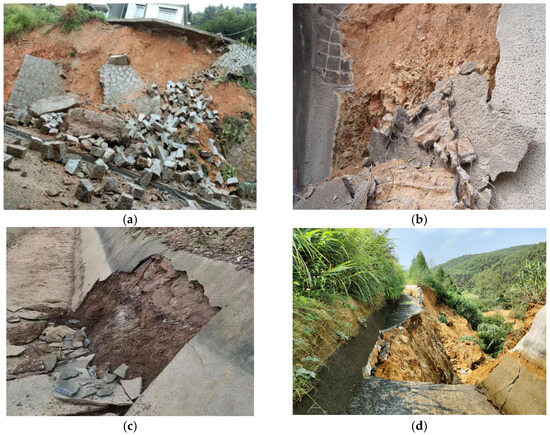
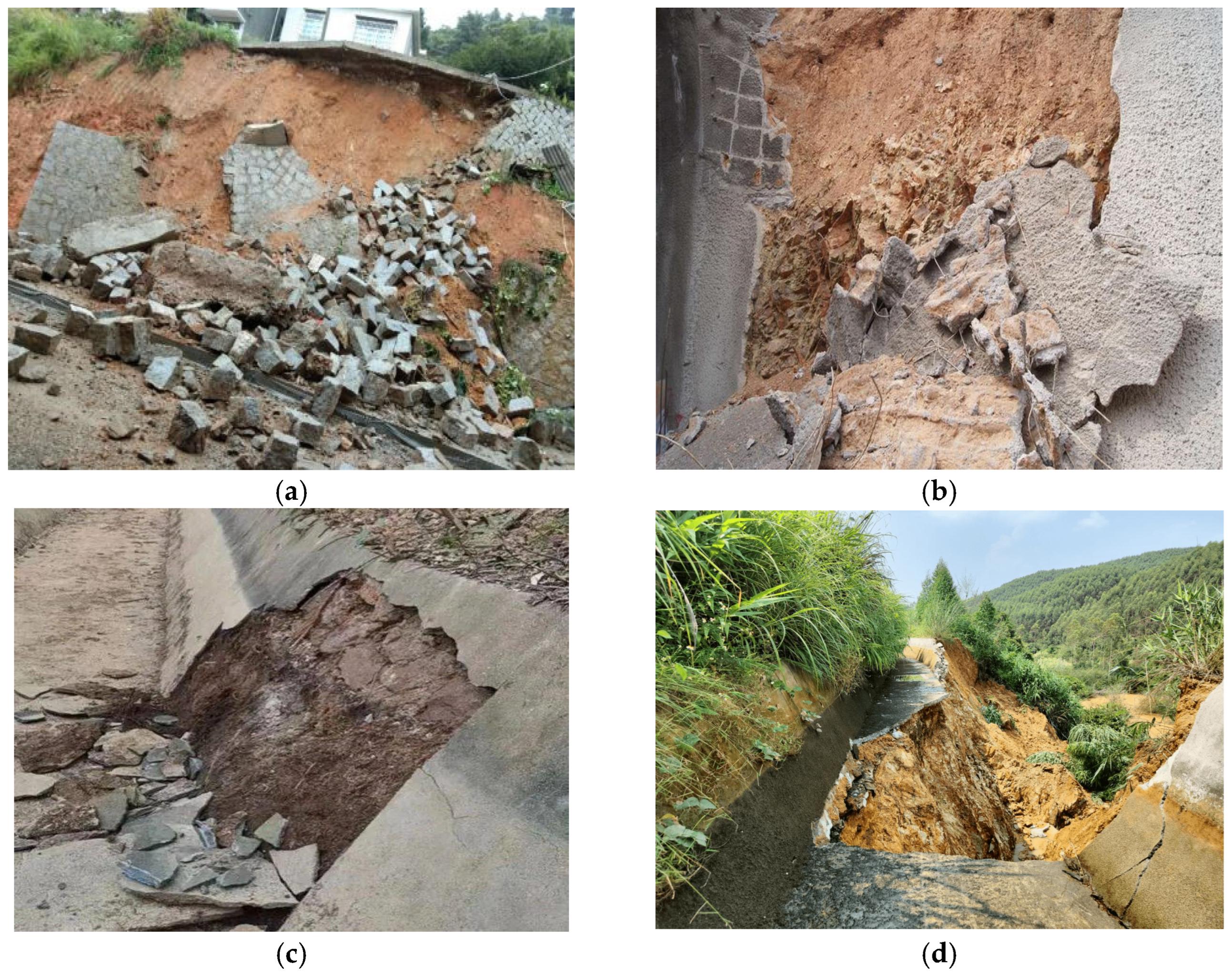
Typical protective concrete structures, such as slope shotcrete layers and drainage ditches, were essential for ensuring the long-term stability and normal operation of infrastructure projects. Traditionally, these structures were constructed using cement-based concrete materials. However, the inherent brittleness of concrete made it prone to cracking failure, particularly when exposed to external conditions, such as temperature fluctuations, wet–dry cycles, and foundation deformations [1,2]. Such failures not only broke the protective capabilities of the structure but can also accelerated the corrosion of embedded reinforcement bars. Over time, more severe engineering issues would potentially occur, such as soil erosion or slope instability, significantly shortening the lifespan of the project and increasing maintenance costs [3]; see Figure 1.
Figure 1.
The crack failures of concrete in slope protective and drainage ditches projects: (a) failure of a slope protection layer in Baoshan Village, Xiping Town, Anxi County, Quanzhou City, Fujian Province on 29 August 2018; (b) slope shotcrete layer failure in Qinhe Town, Yuyang District, Yulin City, Shaanxi Province on 29 February 2012; (c) failure of a drainage ditch in Malei Village, Shilong Town, Xiangzhou County, Laibin City, Guangxi Province on 11 April 2023; (d) failure of a drainage ditch in Hezhou Village, Pumen Town, Babu District, Hezhou City, Guangxi Province on 20 April 2022.
To mitigate the propensity for cracking in concrete, various improvement measures have been explored in engineering applications. These have included the addition of reinforcing bars, optimization of structural layouts, incorporation of fibers (e.g., steel or synthetic fibers), and the use of microbial-induced calcium carbonate precipitation (MICP) [4,5,6,7,8,9]. These approaches contributed to enhanced crack resistance; however, the modified concrete remained fundamentally rigid or semi-rigid in nature. Under repeated deformation stresses, such as those induced by seasonal frost heaving or uneven settlement, concrete is still prone to cracking when subjected to substantial deformation, leading to the loss of its protective function.
Textile-reinforced concrete (TRC) was developed as a solution to address concrete’s vulnerability to cracking under large deformations [3,10,11]. In TRC, corrosion-resistant textile fibers, such as carbon or glass fibers, replace traditional steel reinforcement [12,13]. These fibers provide excellent corrosion resistance and high tensile strength, thereby improving the integrity of protective structures and offering a viable solution for lightweight, thin-walled structures [14,15]. Typically, fibers in TRC are embedded in the concrete as single-layer grids or adhered to the surface with adhesives. However, the fibers may slide out of the concrete mortar prematurely under large tensile forces due to inadequate friction between the fibers and the mortar. Furthermore, TRC components have exhibited weaknesses in resisting concentrated point loads or the impact of sharp objects due to their thin and lightweight nature. As a result, additional design considerations or protective layers may be necessary for applications that demand high impact resistance.
In recent years, flexible concrete blankets, as an innovative cement-based composite material, have gained considerable attention. There has been growing interest in the impact of fiber reinforcement on the mechanical properties of concrete and geosynthetic cementitious composite mat (GCCM). For example, the dynamic behavior of fiber-reinforced concretes was investigated using the impact excitation test, highlighting improvements in stiffness and dynamic modulus through basalt and polypropylene fibers [16]. These blankets incorporate cement-based composites within a three-dimensional fabric, which hardens upon contact with water, displaying excellent compressive strength. The combination of the three-dimensional fabric and the cement-based composite has superior tensile and erosion resistance properties, with an ultimate tensile strain significantly higher than that of conventional concrete. This transformation from brittle to ductile failure fundamentally resolved the shortcomings of traditional rigid materials.
While flexible concrete blankets have demonstrated substantial improvements in mechanical properties and crack resistance, their long-term durability remains a subject of ongoing research, particularly in cold regions or areas with seasonal permafrost. This paper aims to determine the optimal composition of cement-based composite blankets through mechanical testing and to quantify the degradation of material performance under various conditions using accelerated freeze–thaw testing. Additionally, the freeze–thaw damage mechanism is explored through microscopic analysis, providing a theoretical foundation and data support for the safe design and implementation of flexible concrete blankets in cold-region protection projects.
2. Materials and Test Methods
2.1. Material
In this study, various raw materials were utilized in the experiments to prepare flexible concrete blankets, including Portland cement, high alumina cement, fly ash, mineral powder, sand, water, and three-dimensional spacer fabric. High alumina cement was selected due to its rapid hydration reaction, fast setting time, and significant enhancement of early strength development. Fly ash, primarily composed of SiO2 and Al2O3, was chosen for its ability to improve the fluidity of the composite substrate, ensuring uniform slurry consistency and reducing the separation between water and aggregates. The mineral powder employed was slag micro-powder, with an activity index of 95%, predominantly composed of Al2O3 and CaO. The reason for selecting this mineral powder was its capacity to substantially enhance the long-term strength and durability of the cement matrix. Moreover, the inclusion of fly ash and mineral powder aligns with objectives of energy conservation, emission reduction, and the utilization of solid waste materials. Fine sand was incorporated to maintain the uniformity and structural integrity of the flexible concrete blanket. The detailed composition and performance indicators of Portland cement, high alumina cement, fly ash, and mineral powder are presented in Table 1, Table 2, Table 3 and Table 4.
Table 1.
Property indices of P.O425 ordinary Portland cement.
Table 2.
Properties index of CAC 625 high-alumina cement.
Table 3.
Property indices of fly ash.
Table 4.
Property indices of mineral powder.
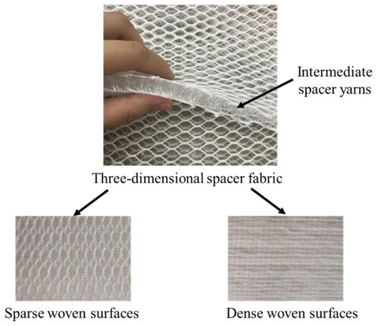
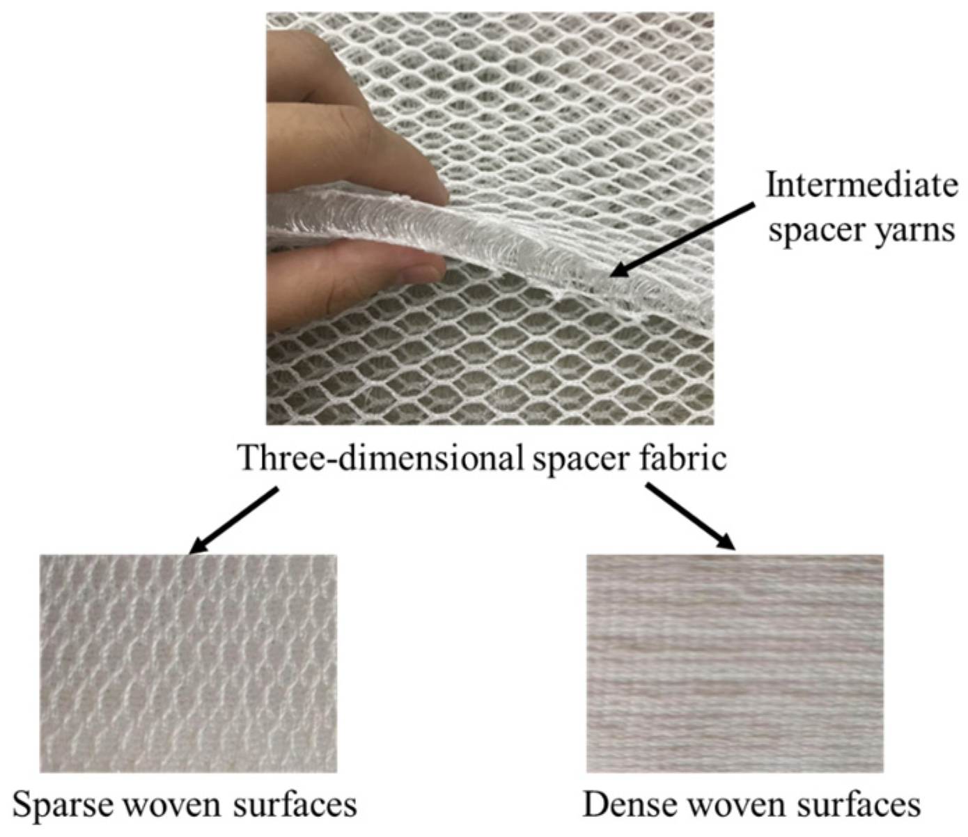
The three-dimensional spacer fabric, a critical component of the flexible concrete blanket, consisted of an interlayer structure comprising sparse woven surfaces with a mesh design and dense woven surfaces without a mesh. These two surface layers are interconnected by intermediate spacer yarns. The fibers forming the three-dimensional fabric were made from polyethylene terephthalate (PET), exhibiting high tensile strength and flexural toughness. The fabric’s areal weight is 1050 g/m2, which contributes to its load-bearing capacity and flexibility. The fabric has a thickness of 10 mm. With respect to the stitch density, the longitudinal knitting density is approximately 9 cpc and the transverse density is approximately 13.5 wpi. When integrated with the cement matrix, it provides exceptional reinforcement and protective properties. In addition, the unique structural design of the fabric not only allows for large-scale deformation after bending but also more effectively disperses stress concentration under impact, thereby enhancing the overall performance of the composite material. The form and detailed structure of the three-dimensional spacer fabric are illustrated in Figure 2.
Figure 2.
The internal structure of three-dimensional spacer fabric.
To address the issue of concrete cracking in drainage ditch and slope protection engineering, this study designed a performance test scheme for a flexible concrete blanket with five different ratios. The ratios were varied by adjusting the proportions of Portland cement to high alumina cement and the cement-to-sand ratio, with the objective of determining the optimal mixture that provides the best performance. The test scheme is presented in Table 5. The specific mix ratios of ordinary Portland cement (P) and high alumina cement (A), as well as the cement-sand ratio (C:S), were selected based on a combination of preliminary pre-experimental results and findings from prior research literature. Preliminary tests identified the initial ranges for the P:A and C:S ratios, which were then refined based on their impact on key material properties, such as compressive strength, flexural strength, and freeze-–thaw resistance. The final ratios used in the study were P:A = 1:1, 2:1, and 1:2 and C:S = 1:2, 2:1, and 1:1, as these were determined to yield the most promising results in terms of material performance and durability under the tested conditions.
Table 5.
Five ratios of cement-based composites in flexible concrete blankets.
2.2. Sample Preparation and Test Methods
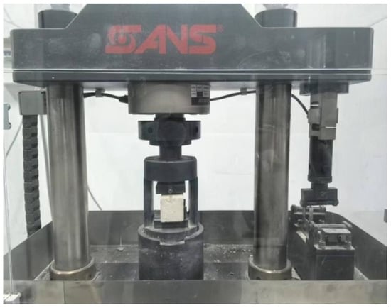
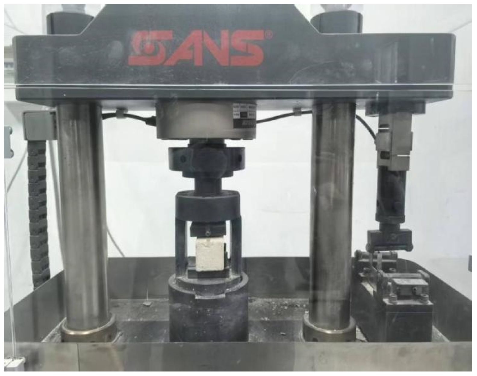
For the compressive strength test, the sample dimensions were set at 40 mm × 40 mm × 40 mm. According to the predetermined mix ratio, the cement, sand, mineral powder, fly ash, and water were weighed during the preparation process. The dry ingredients (cement, sand, mineral powder, and fly ash) were first mixed in a container at low speed for 30 s. Water was then added, and the mixture was stirred at low speed for 60 s, followed by high-speed mixing for an additional 60 s. After mixing, the well-prepared mortar was poured into molds in two stages. Initially, half of the mold was filled with mortar, and continuous vibration was applied for 30 s. The remaining mortar was then added, and vibration continued for 60 s. Once the vibration was complete, the mortar surface was leveled using a ruler. The specimens were then transferred to a curing room, where the temperature was maintained at (20 ± 2) °C, and the relative humidity was kept above 95%. After 28 days of curing, all specimens were demolded. The compressive strength was evaluated using a hydraulic loading device (Figure 3). The pressure testing machine applied a uniform load at a rate of 1 kN/s until specimen failure occurred, and the limited load value at failure was recorded. The compressive strength test was performed following the ISO standard (GB/T17671-2021) [17]. The loading rate during the test was 1 kN/s to ensure consistency with international testing procedures. Meanwhile, three groups of parallel experiments were set up to ensure the accuracy of the experimental data.
Figure 3.
The hydraulic loading device used in the compressive strength test.
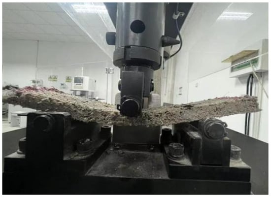
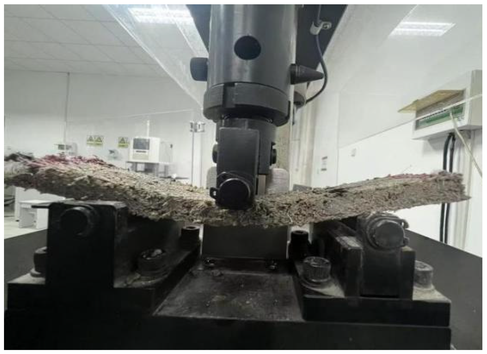
For the flexural and tensile tests, the test specimens consisted of flexible cement-based composite blankets with dimensions of 300 mm × 100 mm × 10 mm. During sample preparation, the raw materials in dry powder form, including the cement, sand, mineral powder, and fly ash, were mixed according to the designed ratio and stirred at low speed to ensure uniformity. A three-dimensional spacer fabric was placed on a vibrating table, and the mixed cement-based powder was gradually filled into the fabric in three stages until the fabric was fully packed. Water was then sprinkled onto the surface of the fabric, and sprinkling continued until the target water–cement ratio was achieved, as determined by the mass difference before and after sprinkling. During the laboratory preparation of the FCB specimens, some difficulties were encountered in ensuring uniform packing of the cement-based powder onto the spacer fabric. The vibration speed and duration were critical in achieving optimal compaction and preventing uneven distribution of the material. On-site execution of this process would require the use of mechanized or semi-automated equipment to efficiently fill the fabric with the cement-based powder. A vibrating table or similar vibration equipment could be used to ensure uniform packing and to eliminate voids in the fabric, thus ensuring consistent material properties and performance. These practical considerations for scaling the process to on-site applications have been taken into account in the design. The flexible concrete blankets were then placed in a standard curing room, where the temperature was maintained at (20 ± 2) °C, and the relative humidity exceeded 95%. All specimens were demolded after curing for 28 days. For the flexural strength test, the cured flexible concrete blanket specimen was placed on the support mold of the testing machine, ensuring that the side of the specimen was perpendicular to the mold. A concentrated load was applied at the center of the specimen until failure occurred (Figure 4). The maximum load at failure and the position of the fracture at the lower edge of the specimen were recorded. The final flexural strength was calculated as the average value from three parallel specimens.
Figure 4.
The flexible concrete blanket bent during the flexural strength test.
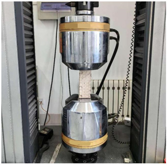
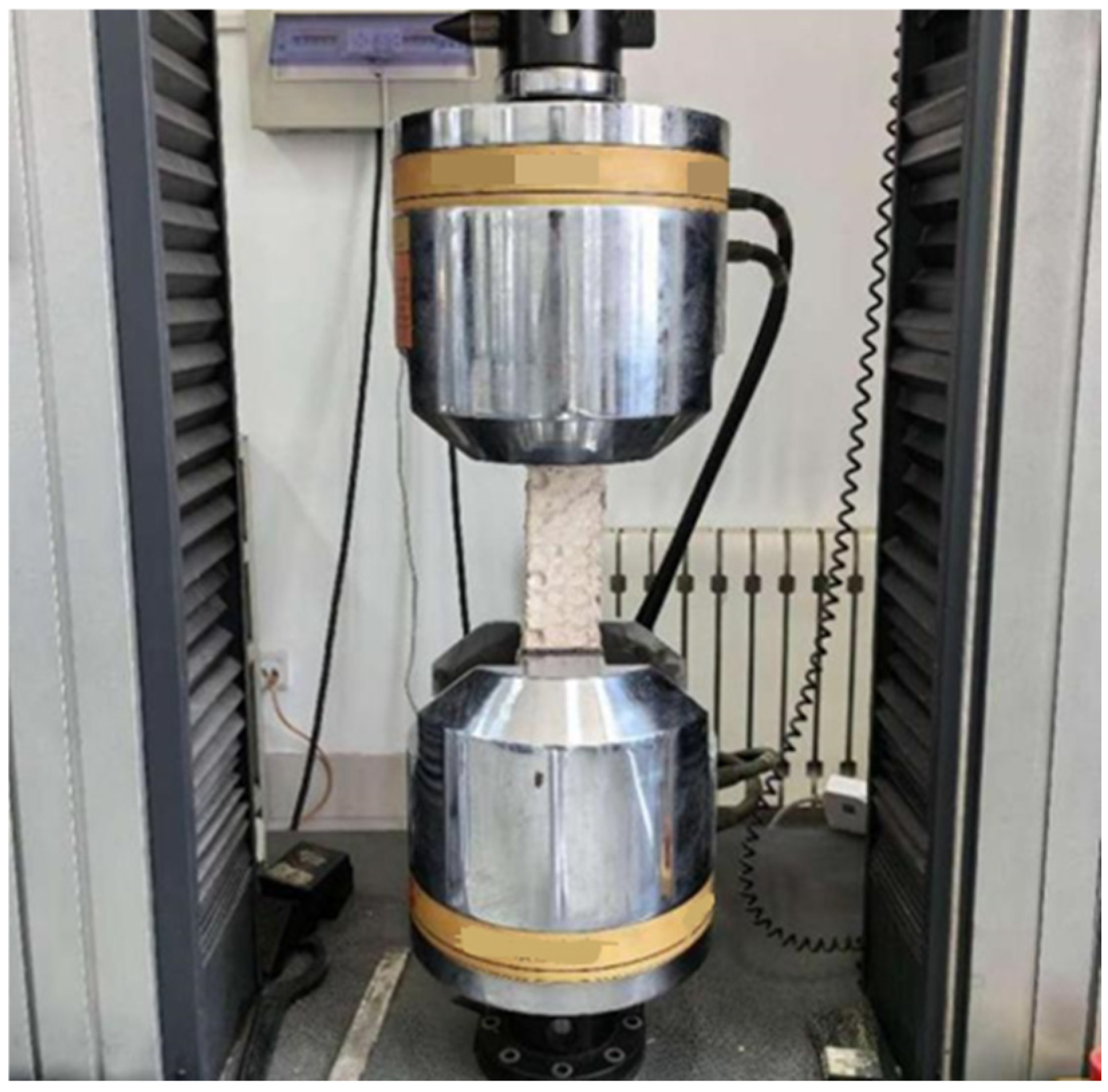
In the tensile strength test, flexible cement-based composite blanket samples measuring 400 mm × 100 mm × 10 mm were used. Both ends of the specimen were securely fixed in the fixtures of a large tensile testing machine, ensuring proper alignment with the loading axis to avoid eccentric loading. The displacement was applied at a rate of 5 mm/min, which was performed following the ISO standard (GB/T17671-2021) [17]. The loading continued until noticeable cracks or damage appeared, and the specimen was subjected to further loading until complete failure. The maximum load at failure was recorded, and the tensile strength of the flexible concrete blanket was subsequently calculated; see Figure 5. The specimen dimensions for the compressive strength, flexural, and tensile strength tests were selected in accordance with the ISO (GB/T17671-2021) [17].
Figure 5.
The flexible concrete blanket in the tensile strength test.
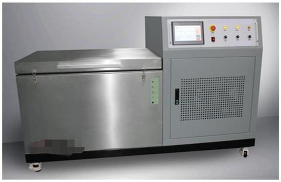
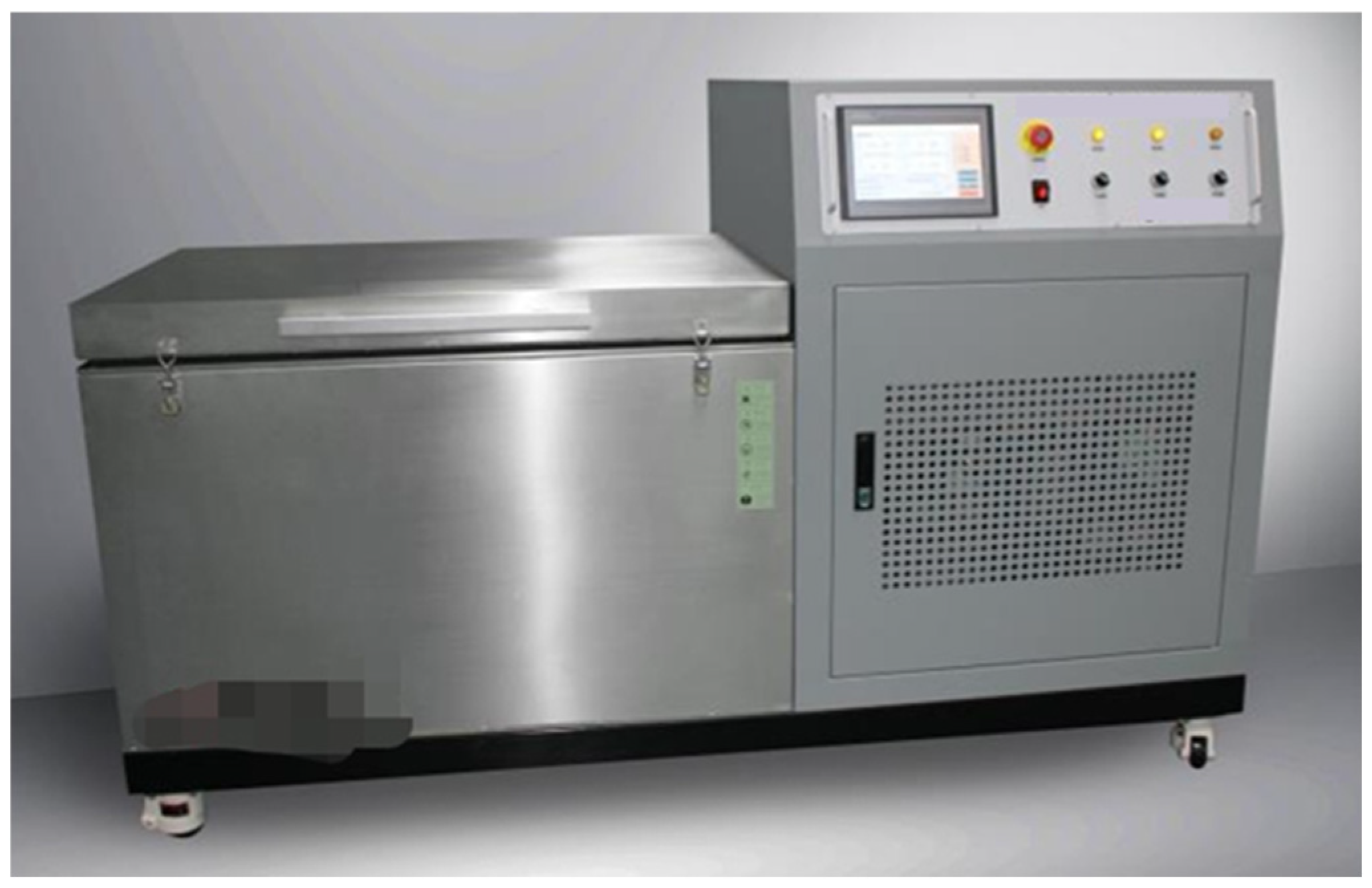
A fully automated concrete rapid freeze–thaw testing machine was employed to carry out freeze–thaw cycle tests, simulating the strength degradation of flexible concrete blankets in cold environmental conditions (Figure 6). Frost resistance tests were conducted on the entire fiber-reinforced concrete block (FCB), including both the concrete matrix and the fiber reinforcement. This method was consistent with the approach used for the flexural strength tests, allowing for the evaluation of the material’s behavior as a whole under freeze–thaw conditions. Prior to initiating the freeze–thaw tests, key parameters of the specimens, such as initial mass and compressive strength, were measured sequentially, and then the specimens were placed in a container. Next, water solution was added to the container, ensuring that the liquid level remained no less than 5 mm below the top of the specimen. The specimen box was then placed in the freeze–thaw cycle testing machine. During the test, the minimum temperature in the freezing phase was maintained at −18 °C for a duration of 3 h, after which the specimens were allowed to return to room temperature (25 °C). A total of 25 freeze–thaw cycles were defined as one complete test period. After each period, the specimens were removed from the testing machine, the surface moisture was wiped dry, and performance indicators, including mass loss rate and compressive strength, were measured. Note that the testing procedure was immediately terminated when the specified number of freeze–thaw cycles (125 cycles) was reached, when the loss in compressive strength exceeded 20%, or when the mass loss exceeded 5%. A total of 15 specimens were prepared for the freeze–thaw testing. For each specified freeze–thaw cycle (25, 50, 75, 100, and 125 cycles), three specimens were tested to determine the compressive strength after exposure to the cycles. The number of 125 freeze–thaw cycles was chosen based on the standard test methods for evaluating the long-term performance and durability of concrete (GB/T50082-2024) [18], aligning with established protocols for durability testing of concrete and similar materials. This number provides an accelerated aging scenario that simulates extreme freeze–thaw exposure to stress-test the materials under worst-case conditions. Although it may exceed typical real-world exposure, this test is intended to evaluate the long-term durability of the material and to provide an accelerated durability benchmark. The freeze–thaw cycles used in this study reflect the surrounding environment conditions of alternating hot and cold commonly employed in similar research.
Figure 6.
Fully automatic concrete rapid freeze–thaw testing machine.
To better quantitatively describe the degradation of flexible concrete blankets during freeze–thaw cycles, some evaluation indicators were defined, including mass loss rate, relative compressive strength, and compressive strength loss rate, etc.
Firstly, the relative mass and mass loss rate of the specimens were calculated using the following formulas:
where mr is the relative mass loss rate after freeze–thaw cycles; m0 is the initial mass (g) of the specimen before testing; mn is the mass (g) of the specimen after n freeze–thaw cycles; Δm is the mass loss rate (%) of the specimen after freeze–thaw cycles.
The compressive strength and its loss rate were determined using the following formulas:
where fr is the relative compressive strength after freeze–thaw cycles; f0 is the initial compressive strength (MPa) of the specimen prior to testing; fn is the compressive strength (MPa) of the specimen after n freeze–thaw cycles; ∆f is the compressive strength loss rate (%) after n freeze–thaw cycles.
3. Results
Firstly, five different mix ratios were designed to determine the optimal mix ratio of the flexible concrete blanket, and a series of tests on the setting time, compressive strength, flexural strength, and tensile strength were conducted. Then, freeze–thaw cycle experiments were carried out to test the changes in its property durability in extremely cold regions.
3.1. Setting Time
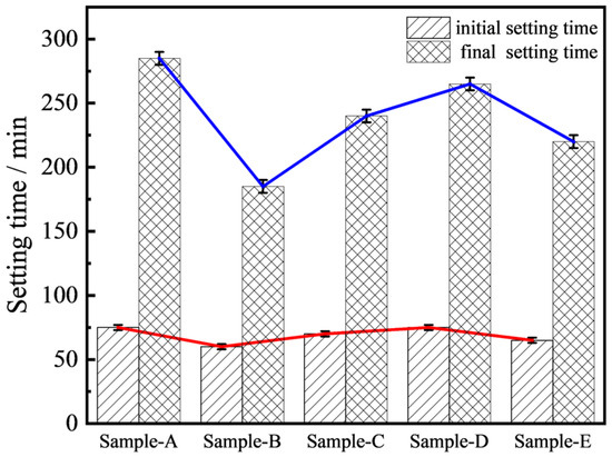
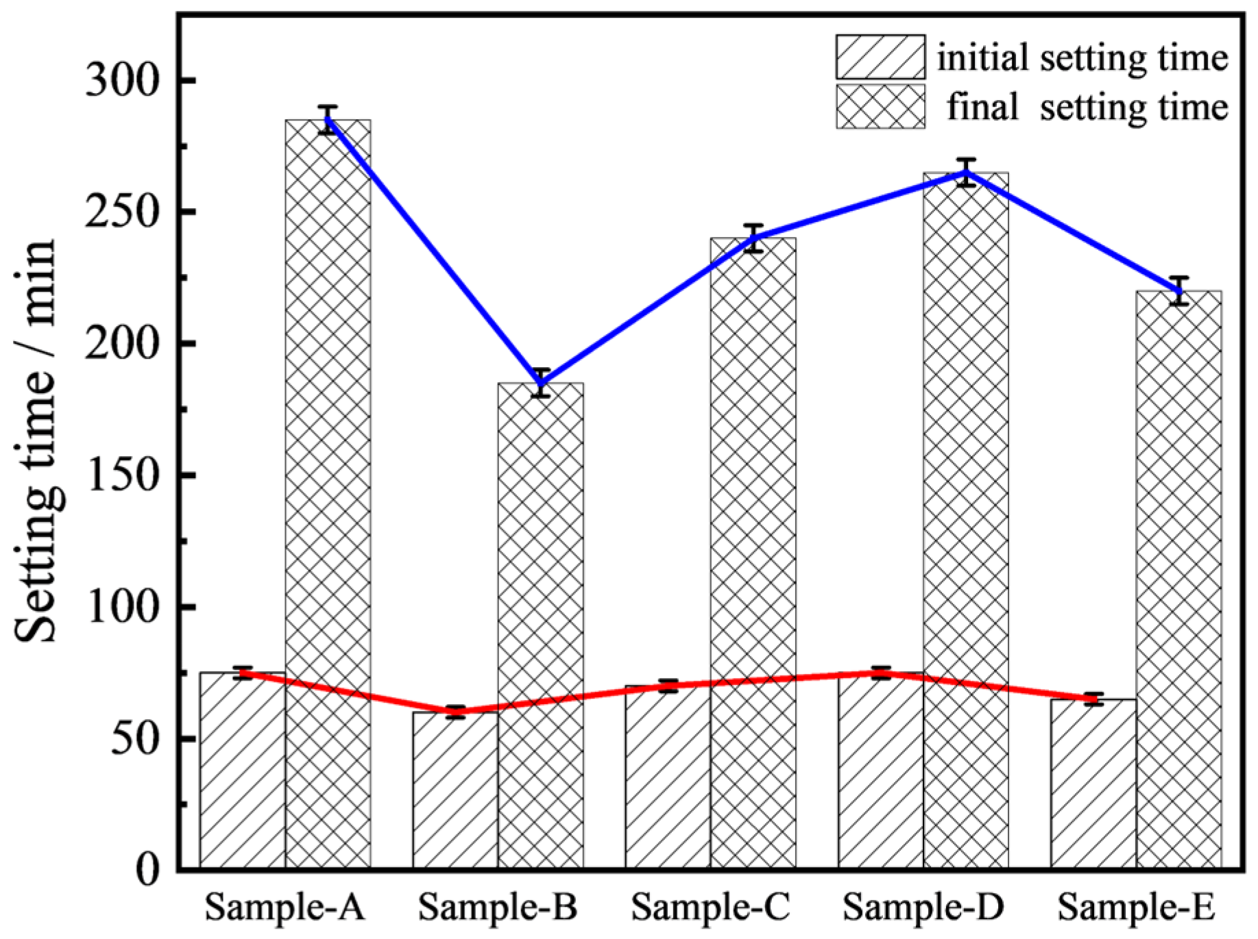
During the setting time tests, the initial and final setting times of the five mix ratios were measured using a Vicat meter. As shown in Figure 7, the initial setting times for the five concrete mixtures with varying ratios exhibited only minor differences, whereas the final setting times showed obvious variation.
Figure 7.
The initial and final setting times of five mix ratios of cement-based composites.
In terms of the initial setting time, Sample B and Sample E had the shortest initial setting time. For Sample B, when the cement-to-sand ratio was adjusted from 1:1 to 2:1, the initial setting time decreased from 75 min to 60 min. Similarly, with respect to Sample E, when the ratio of Portland cement to high alumina cement was fixed at 1:1, the increase in the proportion of high alumina cement led to a gradual shortening of the initial setting time, from 75 min to 60 min. Consequently, the key factors influencing the result were the cement-to-sand ratio and the proportion of high alumina cement, both of which significantly impacted the setting time.
Regarding the final setting time, when the cement-to-sand ratio was 1:1, increasing the proportion of high alumina cement reduced the final setting time from 265 min to 220 min, as shown in Sample E. This reduction can be attributed to the faster hydration and hardening rates induced by high alumina cement. Additionally, when the high alumina cement-to-Portland cement ratio was set at 1:1, increasing the cement-to-sand ratio can shorten the final setting time. For a cement-to-sand ratio of 2:1 in Sample B, the final setting time was reduced to 185 min. This phenomenon is largely due to the increased amount of cementitious material, such as calcium hydroxide and calcium silicate hydrate, which accelerates the formation of hydration products during the hydration process. As the cement-to-sand ratio increases, the volume of these hydration products increases, forming a network structure that gradually transitions the cement matrix of the flexible concrete blanket from a plastic to a hardened state, signaling the completion of the final setting.
3.2. Compressive Strength
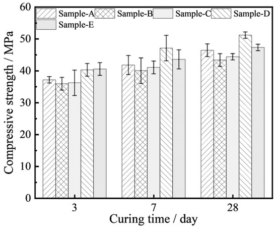
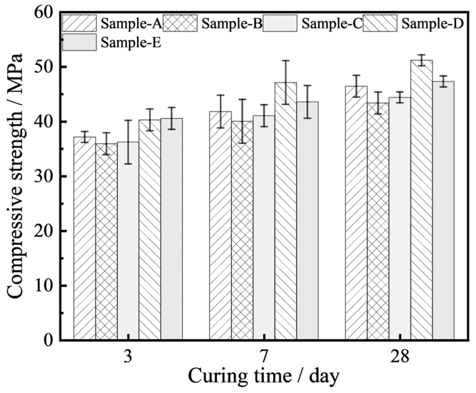
In this experiment, the compressive strength of flexible concrete with different mix ratios gradually increased with the increase in curing time (Figure 8).
Figure 8.
The compressive strengths of the flexible concrete blanket varied with the curing time.
During the early curing stage (3 days), the hydration reaction of cement had only recently commenced and the formation of hydration products remained incomplete, resulting in a relatively loose internal structure and consequently low compressive strength. Only the high-content Portland cement (Sample D) and high-content high alumina cement (Sample E) specimens exhibited relatively high early compressive strength (approximately 40 MPa). High alumina cement is characterized by its rapid setting and high early strength development, primarily due to its mineral components with a high hydration rate, such as calcium aluminate. This rapid hydration generates a substantial amount of calcium aluminate hydrate and other products in the early stage, effectively filling internal pores, forming a dense microstructure, and thus enhancing the early compressive strength. Consequently, the mixtures with a higher proportion of high alumina cement demonstrated higher early strength.
For the intermediate curing stage (7 days), the hydration process of cement entered an active period, with the hydration products gradually increasing and the structure becoming more compact. By the end of the standard curing period (28 days), the hydration reaction of the cement was essentially complete, resulting in a dense microstructure and further enhancement of compressive strength, which subsequently stabilizes. At this stage, Portland cement-based flexible concrete exhibited significantly higher compressive strength compared to its high alumina cement counterpart, as shown in Sample D. This difference was primarily attributed to the potential crystal phase transformation of high alumina cement hydration products at later stages, which may adversely affect structural stability. Elevated ambient temperatures can accelerate this transformation, causing a deceleration or even a reduction in the later-stage strength gain. In contrast, Portland cement underwent a relatively slow hydration process, with limited early-stage product formation. However, continuous hydration at later stages gradually densified the structure, resulting in steady and sustained compressive strength development that ultimately reached a higher level. Therefore, the specimens with a higher Portland cement content demonstrated superior long-term mechanical properties.
The dispersion of compressive strength exhibited significant variability across different curing ages. At 3 days of curing, the data dispersion was minimal, with a standard deviation of approximately 2 to 3 MPa and a coefficient of variation (COV) ranging from 5% to 9%. At 7 days, the dispersion increased, with the standard deviation rising to 3 to 4 MPa and the COV increasing to 7% to 10%. By 28 days, the dispersion further intensified, particularly in Sample D and Sample E, where the standard deviation reached 4 to 5 MPa and the COV ranged from 9% to 12%. Overall, the COV of all samples demonstrated an upward trend with extended curing time. Notably, the strength stability of Sample D and Sample E was consistently lower than that of the other samples. This variation may be attributed to the inhomogeneity in the hydration reactions of the cementitious materials or differences in the evolution of the microstructure.
3.3. Flexural Strength
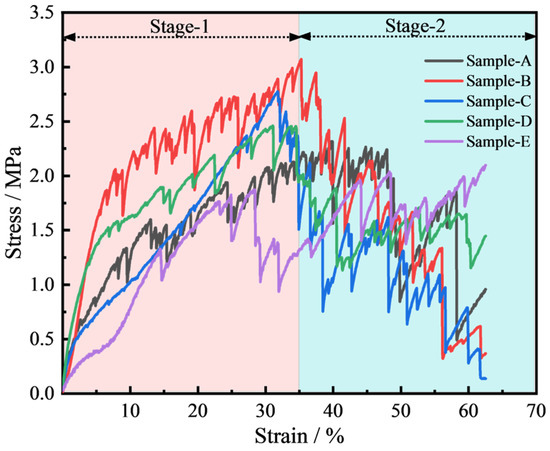
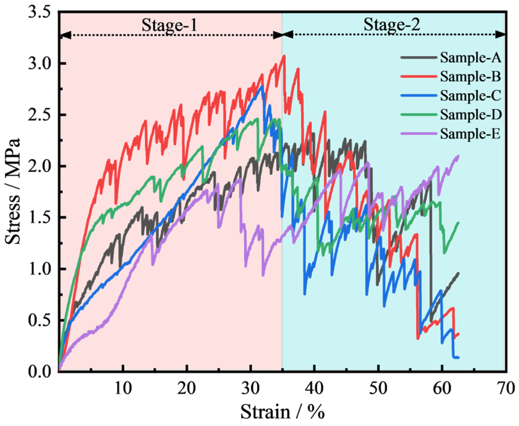
In the flexural strength tests, the stress–strain curves of the five different mix ratios of cement-based flexible composite blankets exhibited similar patterns; see Figure 9. The peak flexural stress ranged between approximately 1.8 and 3.0 MPa. Initially, tensile stress increased progressively with increasing strain; then, the tensile stress began to decrease after reaching its peak as strain continued to rise, indicating the onset of the second stage of deformation. Among the five different ratios, the peak flexural strength of the Sample D mixture was the highest, while that of the Sample C mixture was relatively lower. Notably, owing to the synergistic interaction between the textile fibers and the cementitious matrix, the hardened concrete blanket transitioned from the typical brittle fracture mode observed in conventional concrete to a more ductile failure mode under compressive loading. Furthermore, the material retained a certain level of residual strength after flexural failure, which can be attributed to its distinctive composite structure.
Figure 9.
The flexural stress–strain curves of five flexible concrete blankets with different dosage ratios.
3.4. Tensile Strength
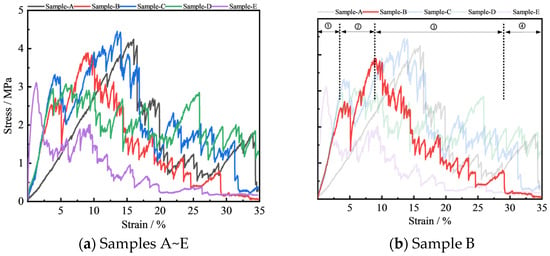
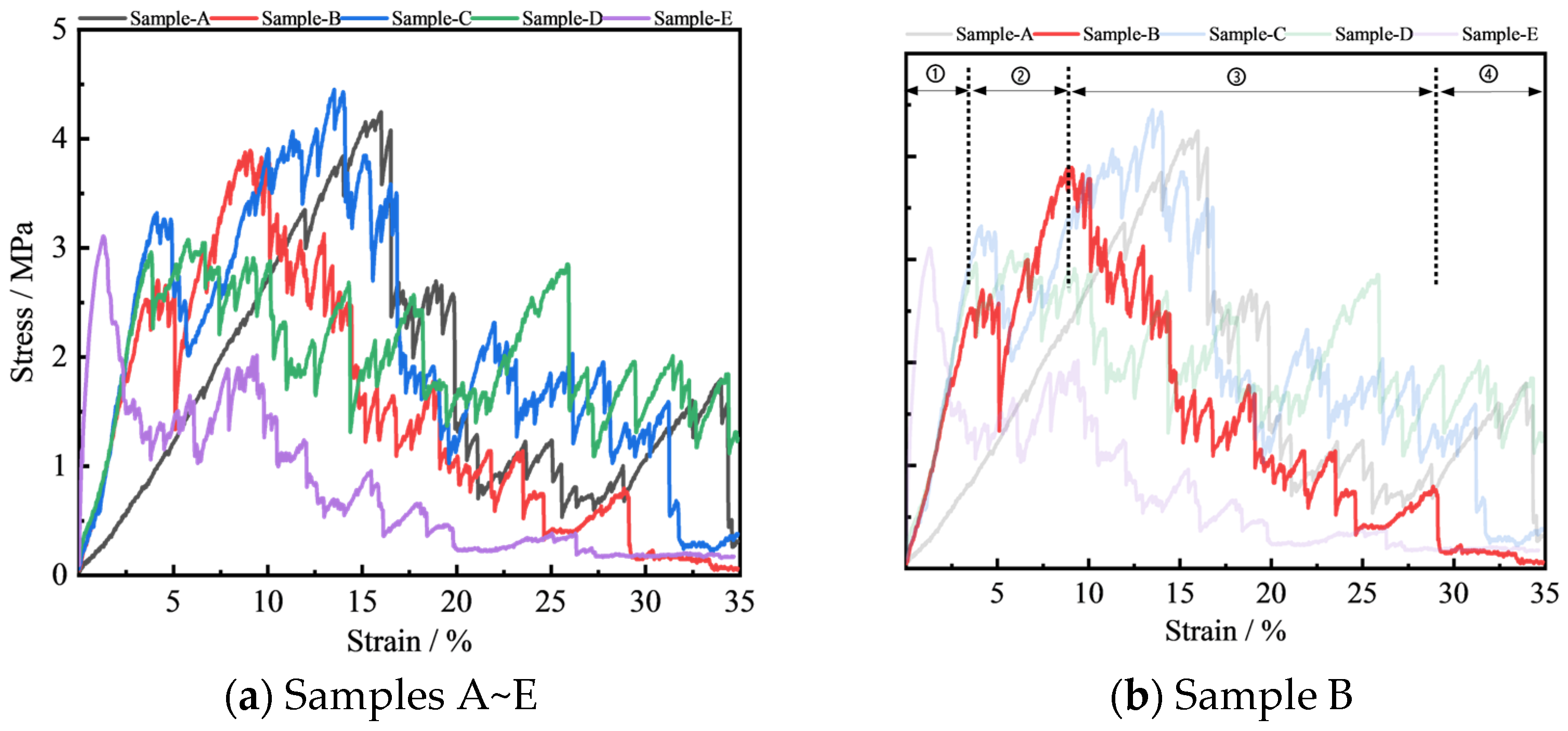
During the tensile tests, the deformation process of the flexible concrete blanket could be divided into four distinct stages (Figure 10).
Figure 10.
The tensile stress–strain curves of five flexible concrete blankets with different mix ratios.
In the initial elastic deformation stage (Stage ①), the stress–strain curve exhibited a linear relationship. The flexible concrete blanket underwent uniform elastic elongation without visible cracking, and the cement matrix bore most of the applied tensile load. Under the small tensile force at this stage, the internal structural microcracks caused by water loss began to be stretched. This stage was reversible, and the material could largely restore its original structure if unloaded.
As the tensile force increased, the curve entered a nonlinear stage (Stage ②). When the tensile stress exceeded the ultimate tensile capacity of the cement matrix, numerous microcracks initiated at its weakest points. Load transfer subsequently occurred from the cracked matrix to the embedded fabric fibers. Owing to the high tensile strength and toughness, the fibers effectively restricted the propagation and widening of these cracks. This stage was characterized by the progressive formation of fine, evenly distributed microcracks with increasing strain. Upon reaching the peak tensile stress, the first visible macroscopic crack formed at the specimen’s weakest section. At this time, the tensile strength is usually 3.1~4.5 MPa, and the tensile strain is 5~16%. At this stage, the cement matrix largely ceased to bear load, serving primarily as a medium to protect and transfer stresses to the fibers, which became the principal load-bearing component.
Following peak stress, strain softening occurred and macroscopic cracks gradually expanded in Stage ③. Some fibers, particularly those with defects or insufficient anchorage, were either pulled out or fractured, resulting in a sudden stress drop.
In the final stage (Stage ④), the majority of the load was borne by the dense woven fabric layer until rupture occurred. Complete failure did not occur instantaneously, as only a portion of the fibers fractured, leaving the remaining fibers intact and sustaining a residual load.
Across the five mix ratio tests, the flexible concrete blanket exhibited a strain capacity ranging from 5% to 15%, with peak tensile strengths between 3.0 and 4.5 MPa. At peak tensile loading, the specimens demonstrated ductile rather than brittle failure, indicating their ability to sustain substantial deformation prior to fracture. This behavior suggests that the dimensional interval fabric effectively enhances the material’s tensile performance and provides a significant reinforcing function.
3.5. Freeze–Thaw Cycle Test
3.5.1. Appearance
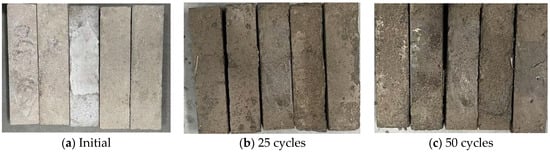
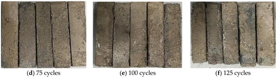
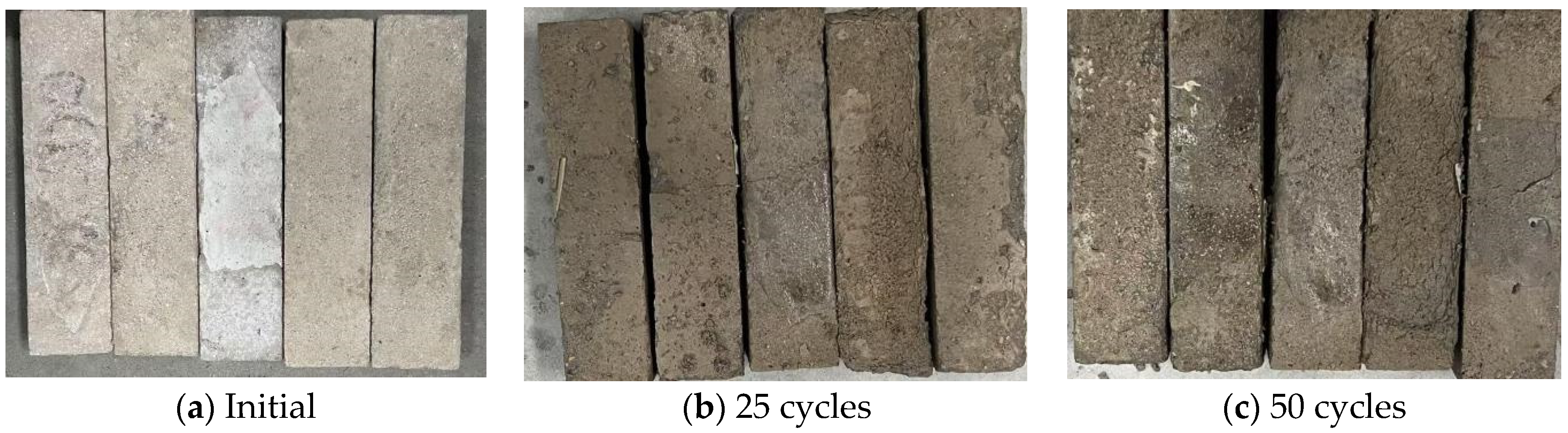
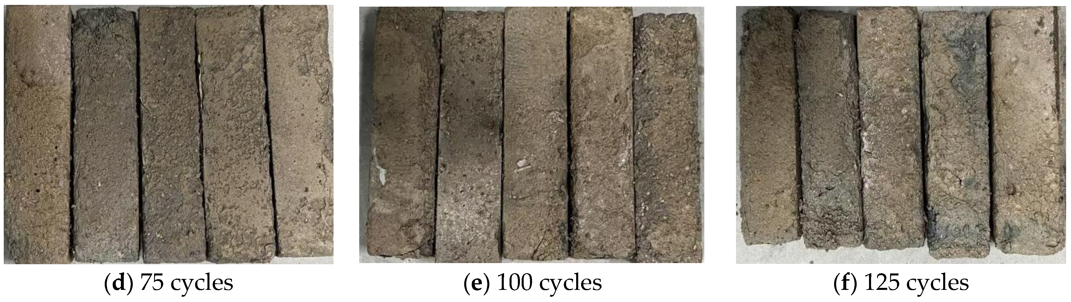
Further freeze–thaw cycle tests were carried out to verify the property durability of the samples in harsh environments. As shown in Figure 11, the extent of surface damage of the specimens progressively intensified as the freeze–thaw (F–T) cycles increased, exhibiting distinct stage-wise characteristics.
Figure 11.
The appearance changes in the flexible concrete blanket after freeze–thaw cycles.
Initially, the specimen surface was smooth without any damage, showing no visible deterioration; see Figure 11a. After 25 cycles, the specimen entered a stage of slight damage. The surface remained largely intact without apparent defects; however, a noticeable darkening of the overall color was observed; see Figure 11b. At 50 cycles, the specimen exhibited initial damage, characterized by the emergence of dense micropores on the surface and the shedding of minor cement mortar particles. Consequently, the surface texture transitioned from smooth to rough, as shown in Figure 11c. Following 75 cycles, the sample entered a moderate damage stage (Figure 11d). Pronounced peeling occurred on the surface, accompanied by localized particle detachment. Repeated phase transitions between liquid and solid states within the pore structure induced internal microcracking under cyclic freeze–thaw stress, further exacerbating surface roughness; see Figure 11d. Upon reaching 100 cycles, the sample entered a severe damage stage. The peeling of the thin mortar layer on the surface of the specimen intensified considerably. The surface displayed pronounced depressions and unevenness. Aggregates in some areas began to be exposed, fine cracks gradually expanded, and a certain degree of small debris fell off the specimen; see Figure 11e. After 125 cycles, fine cracks developed into penetrating macrocracks, accompanied by substantial surface mortar spalling, extensive exposure of coarse aggregates, and gravel shedding. The specimen structure became markedly loose, with both coarse and fine aggregates undergoing partial separation; see Figure 11f.
The above observations demonstrate that freeze–thaw-induced damage intensified progressively with an increasing number of cycles. Approximately 50 cycles represent the threshold at which initial deterioration became apparent. At 75 cycles, notable surface damage was observed, including spalling and particle shedding. Further exposure to 125 cycles resulted in a pronounced escalation of surface deterioration and a marked increase in the failure rate of the specimens.
3.5.2. Mass Change
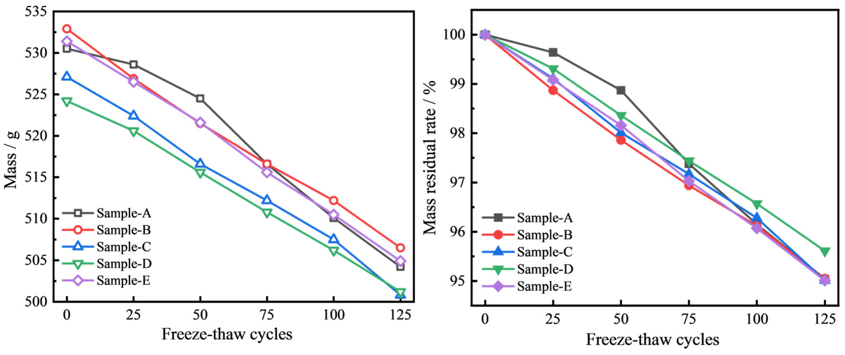
As the number of freeze–thaw cycles increased, the mass loss of the specimens exhibited a two-stage pattern characterized by a gradual decline in the initial phase, followed by accelerated deterioration in the later stages; see Figure 12.
Figure 12.
Mass loss and mass residual ratio of flexible concrete blankets after freeze–thaw cycles.
At 25 cycles, mass loss rates varied slightly across the specimen groups. The Sample A group showed the lowest reduction at 0.36%, while the Sample E, Sample C, and Sample D groups experienced losses of 0.92%, 0.89%, and 0.69%, respectively. The Sample B group exhibited the highest initial mass loss of 1.13%. The relatively low mass loss in the Sample A group can be attributed to its denser internal structure, which features smaller pores and limited connectivity, thereby restricting water infiltration and reducing the effects of frost heaving. In contrast, the higher mass loss in the Sample C group was due to the larger internal pores within this mix ratio, which allowed greater water penetration and increased susceptibility to cracking and freeze–thaw damage.
As the freeze–thaw cycles increased, cumulative damage became more pronounced in all groups. By 75 cycles, the mass loss rates significantly increased, reaching 2.56%, 2.62%, 2.83%, 2.97%, and 3.06% for the Sample D, Sample A, Sample B, Sample E, and Sample C groups, respectively. This stage was marked by crack propagation, mortar detachment, and gradual structural degradation, which was caused by the repeated freeze–thaw stresses that disrupted the balance between cement hydration products and aggregates.
After 125 cycles, the deterioration became significantly more severe, with large-scale mortar spalling and exposure of aggregates. The mass loss rates increased further to 4.39% (Sample D), 4.95% (Sample C), 4.96% (Sample A), 4.99% (Sample B), and 4.99% (Sample E). The cumulative early-stage damage, expansion and interconnection of internal cracks, and considerable loss of cement paste contributed to significant structural impairment.
These results illustrate that the frost resistance performance varied substantially across the different mix ratios, with the Sample D group exhibiting the lowest mass loss and, consequently, the highest resistance to freeze–thaw degradation.
3.5.3. Compressive Strengths
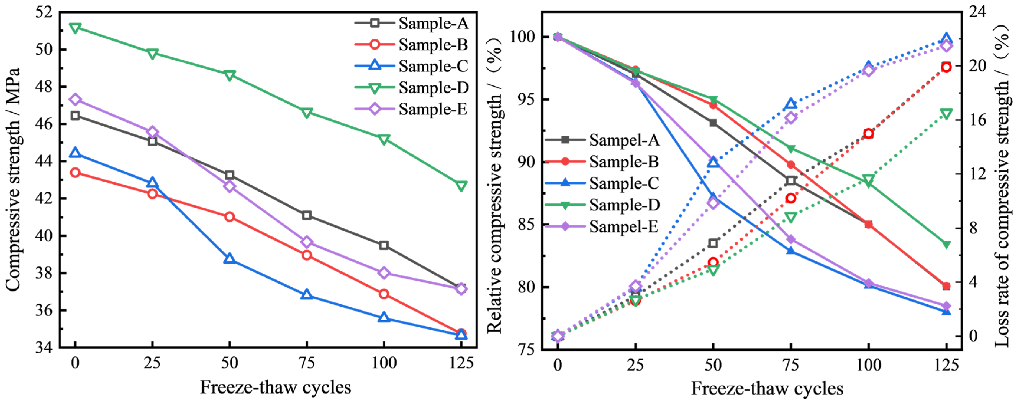
The compressive strengths of the five specimen groups with different mix ratios subjected to freeze–thaw cycles are illustrated in Figure 13.
Figure 13.
Changes in compressive strength of the flexible concrete blanket after freeze–thaw cycles.
In the initial state, the hydration products of the cement effectively bonded the aggregates and other components together, resulting in a stable and cohesive internal structure.
After 25 freeze–thaw cycles, a decline in compressive strength was observed across all groups. Specifically, the Sample B group and the Sample D group exhibited the smallest reductions, with decreases of 2.63% and 2.70%, respectively. The Sample A group saw a reduction of 2.97%, the Sample C group saw a decrease of 3.6%, and the Sample E group experienced the highest loss at 3.70%. These results suggest that the Sample C and Sample D groups maintained relatively stronger compressive strengths at the onset of the freeze–thaw cycles. This might be due to the denser internal structure of these groups, which restricts water entry and minimizes the impact of freeze–thaw damage.
As the number of freeze–thaw cycles increased from 25 to 75, the rate of compressive strength reduction accelerated significantly. At this stage, the compressive strength of the specimens was as follows: Sample D decreased to 95.04%, Sample B to 94.54%, Sample A to 93.13%, Sample E to 90.15%, and Sample C to 87.21%. The observed acceleration in strength reduction suggests that the destructive effects of freeze–thaw cycles progressively intensified as the cycles accumulated. The increase in internal damage was due to the expansion of cracks formed during the initial cycles, which weakened the structural integrity of the concrete. In the later stages, both the frost heaving force in the frozen state and the osmotic pressure from liquid infiltration contributed to pore leakage and crack expansion, further exacerbating the internal damage and accelerating the reduction in compressive strength.
From 75 to 125 freeze–thaw cycles, the rate of compressive strength loss reached its peak. The compressive strength of the Sample D group decreased to 83.46%, while those of the Sample B, Sample A, Sample D, and Sample C groups dropped to 80.09%, 80.04%, 78.51%, and 78.02%, respectively. This sharp decline is attributed to the cumulative damage caused by the freeze–thaw cycles. As cracks propagated and interconnected, the concrete structure became significantly looser, weakening the bond between aggregates and the cement matrix. At this stage, the combined effects of frost heaving and osmotic pressure further promoted crack expansion and coalescence. Originally isolated small cracks interconnected to form larger cracks, severely compromising the concrete’s ability to withstand external pressure and causing a sharp decline in compressive strength.
The compressive strength loss of the Sample D group was the smallest, indicating that a higher Portland cement content helped fill the internal pores of the concrete, thereby increasing the density of the concrete and enhancing its resistance to freeze–thaw degradation. Conversely, the Sample A and Sample B groups had an inappropriate ash–sand ratio, resulting in more internal pores and a looser structure, which led to greater compressive strength loss during the freeze–thaw cycles. In the case of the Sample C and Sample E groups, the insufficient cement ratio, particularly an excessive amount of high alumina cement, caused the hydration products to undergo crystalline transformations under freeze–thaw conditions. This led to structural loosening, reduced frost resistance, and a significant loss of compressive strength.
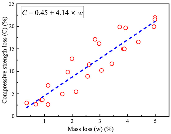
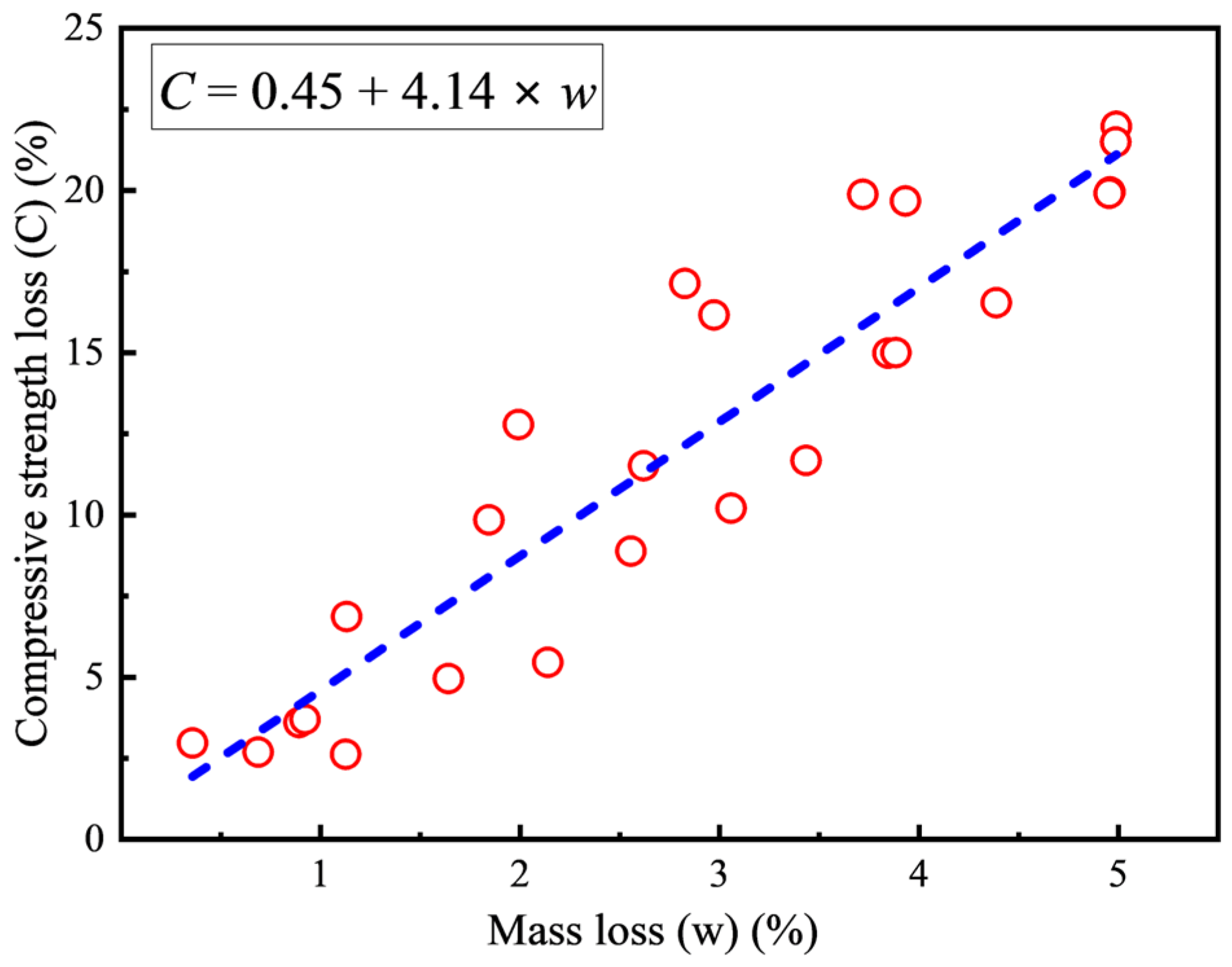
A quantitative relationship between the compressive strength loss rate (C, %) and the mass loss rate (w, %) of the specimens was established. As depicted in Figure 14, an increase in the mass loss rate corresponds to a marked linear rise in the compressive strength loss rate. The relationship between the two variables can be accurately represented by the fitting equation (C = 0.45 + 4.14 × w). When the mass loss rate is relatively low (<1%), the compressive strength loss remains below 5%. However, as the mass loss rate reaches 5%, the strength loss escalates to approximately 21%. This trend highlights the substantial detrimental effect of mass loss on the compressive performance of the materials. The distribution of scattered points around the fitting line further indicates a strong linear correlation.
Figure 14.
The relationship between mass loss and compressive strength loss.
3.5.4. X-Ray Diffraction (XRD)
To investigate the impact of freeze–thaw cycles on the composition of flexible concrete blankets with varying mix ratios, X-ray diffraction (XRD) experiments were performed using an X-ray diffractometer.
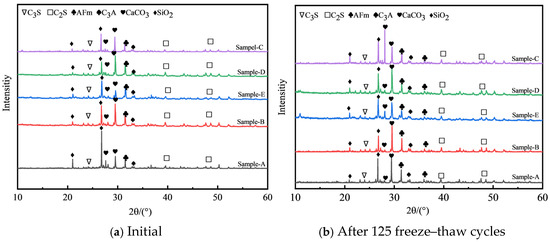
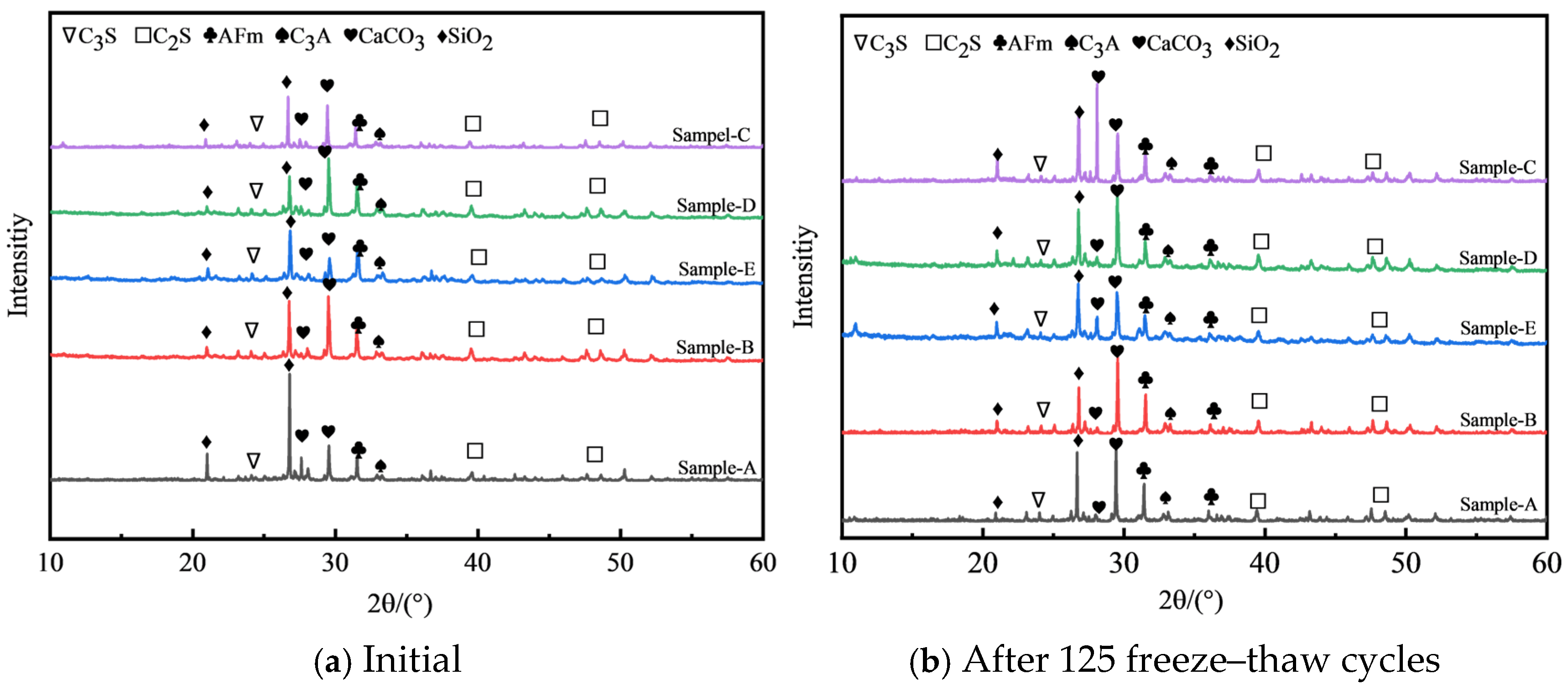
As shown in Figure 15, the primary hydration products identified include monosulfides such as calcium sulfoaluminate (AFm), calcium carbonate (CaCO3), calcium aluminate hydrate (C3A), dicalcium silicate (C2S), and tricalcium silicate (C3S). The diffraction peaks at lower angles suggest the possible presence of calcium silicate hydrate (C-S-H gel) and aluminum gel. Although the hydration products across the different mix ratios of flexible concrete blankets are largely consistent, with no new hydration phases generated, the intensities of the diffraction peaks vary. Variations in cement content, resulting from different mix ratios, led to differences in the diffraction intensities of AFm, C2S, and C3S. This can be attributed to the reduced cement content when sand was added, along with the influence of sand gradation and particle shape, which simultaneously affected the performance of the cement matrix. A reduction in the contents of C2S and C3S in the cement slowed down the hydration process, subsequently lowering the overall cement strength.
Figure 15.
X-ray diffraction (XRD) patterns of flexible concrete blankets.
Mineral powders and fly ash promote the hydration reactions within the composite cementitious material system. Upon dissolving in water, they react with calcium hydroxide (Ca(OH)2) to form secondary gypsum (CaSO4•2H2O), exhibiting a high degree of dispersion. This secondary gypsum further reacts with tricalcium aluminate (C3A) and tetracalcium ferric aluminate (C4AF), leading to the formation of products such as AFt, hydrated calcium aluminate, and hydrated calcium ferrate. These reactions reduce the calcium hydroxide content in the system, accelerating the overall hydration process. However, due to the low dosages of mineral powder and fly ash, no diffraction peaks for ettringite were detected in the results. In contrast, ettringite was found to be converted into AFm.
3.5.5. SEM Analysis
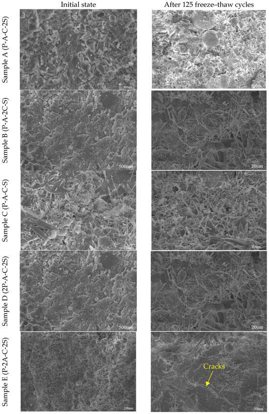
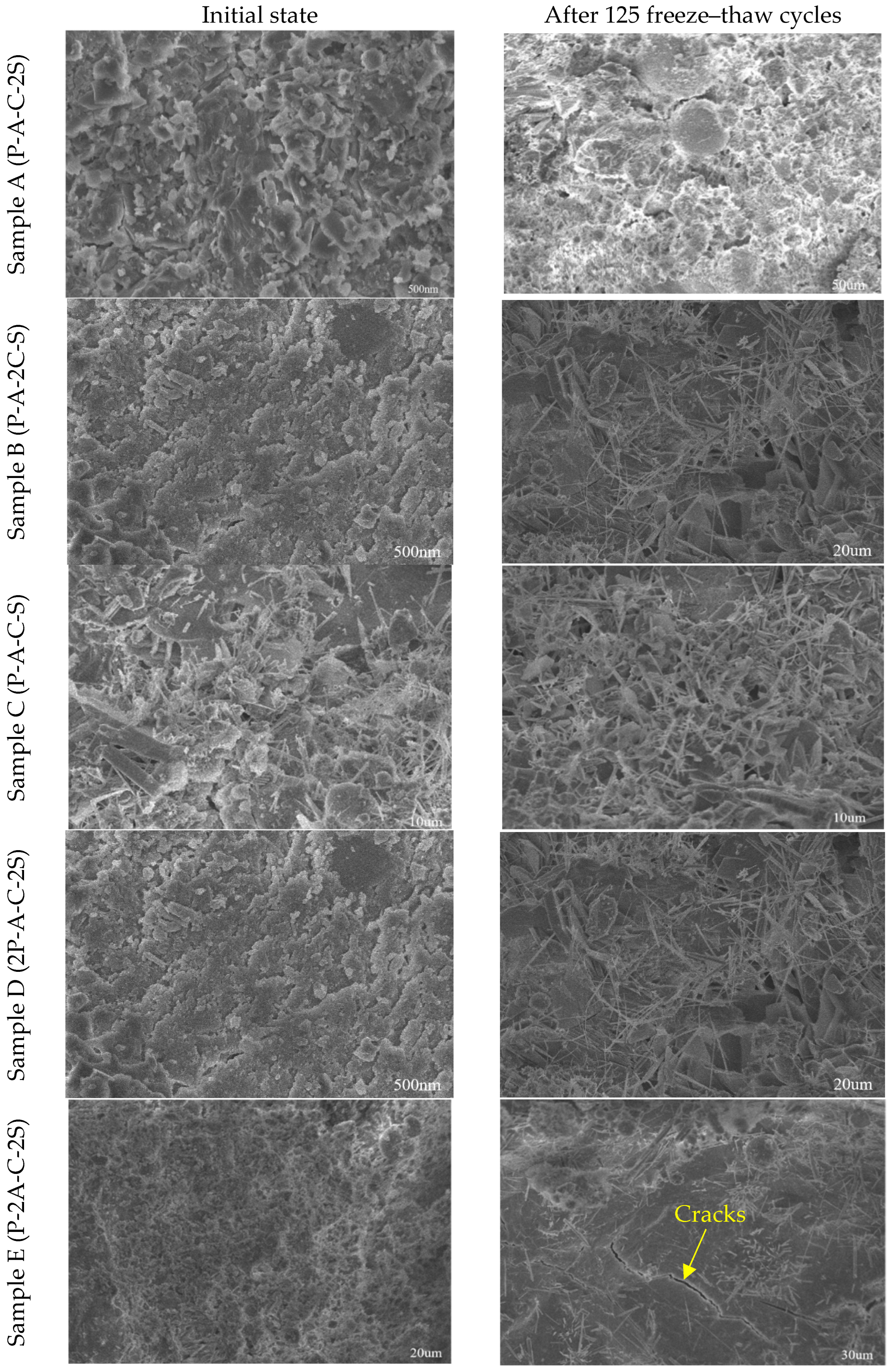
The macroscopic damage due to freeze–thaw cycles in the flexible concrete blanket originated from minor alterations in the internal structure. To investigate the deterioration mechanisms underlying the material’s mechanical properties from a microscopic perspective, the scanning electron microscope (SEM) method was employed.
As shown in Figure 16, the surface of the flexible concrete blanket under normal curing conditions was relatively dense, exhibiting tight inter-particle connections, fewer pores, and a uniform distribution of components. However, after 125 freeze–thaw cycles, the inter-particle bonds weakened, resulting in noticeable fractures and peeling in certain areas. As the freezing and expansion of water within the pores increased internal pressure, cracks developed on the surface, ultimately compromising the structure of the flexible concrete blanket.
Figure 16.
SEM images of the flexible concrete blanket in its initial state and after 125 freeze–thaw cycles.
Microscopically, the fundamental cause of failure in the flexible concrete blanket during freeze–thaw cycles was the periodic frost heaving force. As the number of freeze–thaw cycles increased, the pore water within the material froze, causing it to expand in volume. This expansion exerted continuous pressure on the intergranular cementation, deteriorating the mechanical properties and weakening the bonding strength. The repetitive action of the frost heaving force led to crack formation, particularly in weak zones such as the pore edges and the interface between the binder and particles. With each freeze–thaw cycle, the expansion of ice and moisture migration promoted crack propagation, linking pores and weak areas, and ultimately forming a crack network that led to material failure.
During the freeze–thaw process, moisture within the material repeatedly transitioned from liquid to solid and back to liquid. The freezing of water into ice caused the volume of the sample to expand and the pores to enlarge. When the ice melted, the resulting water penetrated deeper into the specimen due to gravity and capillary action, further eroding the pore walls and cementitious material. This migration of soluble components with the water flow caused uneven distribution of the cementitious materials, further diminishing the inter-particle bonding strength. After multiple freeze–thaw cycles, the macroscopic properties of the specimens became increasingly apparent. The intergranular cementation was severely compromised, with some particles becoming free, while the pores continued to enlarge. The combined effects of frost heaving, water erosion, and temperature changes caused surface particles to gradually peel off.
From a mechanical perspective, the freeze–thaw expansion force induced triaxial tensile stress within the material. This triaxial tensile load, resulting from periodic freeze–thaw expansion, can be viewed as a form of low-cycle fatigue load applied in unidirectional tension. In specimens with a high silicate cement content and a cement–sand ratio of 1:1, the cement hydration process generated a substantial amount of products that formed a dense microstructure. The cement paste thoroughly encapsulated the aggregates, creating a large contact area and thick binder layer. This structure facilitated the even distribution of the frost heaving force, reducing stress concentrations and enhancing inter-particle bonding. Consequently, this configuration effectively limited displacement and minimized damage to the cementitious materials caused by the frost heaving force.
From a macroscopic viewpoint, the specimens with optimized mix proportions demonstrated superior mechanical performance during freeze–thaw cycles. These specimens exhibited a high compressive strength retention rate, low mass loss, and enhanced resistance to deformation, thus ensuring the long-term durability of the engineering structure.
4. Discussion
The experimental results reveal that the mechanical and durability performance of flexible concrete blankets (FCBs) was significantly influenced by both the cementitious composition and the freeze–thaw cycling conditions.
4.1. Flexible Blanket Compared to Other Materials
Compared with traditional rigid or semi-rigid concrete structures, the FCB exhibited distinct advantages in tensile and flexural performance due to the integration of three-dimensional spacer fabrics and optimized cementitious compositions. Traditional cement-based concrete was inherently brittle, with typical tensile strengths ranging from 2 to 5 MPa and flexural strengths of around 3–5 MPa, but it exhibited low strain capacity (often less than 0.1%), leading to sudden failure under deformation. In contrast, the FCB samples in this study achieved tensile strengths of 3.1–4.5 MPa with ultimate strains of 5–16%, transitioning from brittle to ductile failure modes due to the synergistic interaction between the three-dimensional spacer fabric and the cement matrix. This enhanced ductility was attributed to the bridging effect of fabric fiber, where fibers restricted crack propagation and allowed for load redistribution, as observed in the four-stage tensile deformation process (elastic, nonlinear, strain softening, and residual load-bearing).
Comparisons with other fiber-reinforced concretes, such as basalt fiber-reinforced concrete (BFRC), reveal similar improvements in mechanical performance. Reviews of BFRC indicate that basalt fibers enhance tensile and flexural strengths by 10–30% compared to plain concrete, with optimal dosages around 0.1–0.5% by volume and fiber lengths of 3–12 mm, leading to compressive strengths exceeding 40 MPa and flexural strengths up to 6–8 MPa in standard mixes [19,20,21]. In this study, the optimal Sample D mix (higher Portland cement content with a 1:1 cement–sand ratio) yielded compressive strengths approaching 51.2 MPa at 28 days, which aligns with or surpasses reported BFRC values. The flexural strength (1.8–3.0 MPa) was somewhat lower but compensated by the FCB’s flexible structure, which enables large deformations without complete failure. Furthermore, when compared to textile-reinforced concrete (TRC), which uses carbon or glass fibers for crack resistance but often suffers from fiber slippage under high tensile loads, the FCB’s three-dimensional fabric integration offered better stress dispersion and impact resistance. In comparison to the previous findings on fiber-reinforced concretes, our study also showed a significant improvement in the mechanical properties of flexible concrete blankets with fiber reinforcement [15]. Specifically, the dynamic elastic modulus increased by up to 23% with basalt and polypropylene fibers, consistent with the observations in the dynamic characterization study. Commercial GCCMs, such as concrete canvas, typically report 24 h compressive strengths of around 40–50 MPa and indirect flexural strengths ≥ 4 MPa at 24 h, with 28-day values often in the 50–80 MPa range depending on curing. The present FCB optimal mix (51.2 MPa at 28 days) fell within this range, while the exceptionally high tensile strain (up to 16%) highlights the effectiveness of the custom 3D PET spacer fabric compared to standard 2D textile reinforcements in TRC, which can suffer from fiber pull-out.
While FCB is a highly durable material with excellent mechanical properties, it is inherently impermeable. As such, when using FCB in outdoor applications or areas exposed to heavy rainfall, additional drainage solutions should be considered. These could include the incorporation of drainage channels, porous layers, or subsurface drainage systems to facilitate water flow and prevent water accumulation on the material surface. This ensures that the material performs optimally and avoids issues related to hydrostatic pressure or surface damage. While this study primarily focused on the performance characteristics of FCB, we acknowledge the importance of economic considerations for practical implementation. A preliminary financial comparison indicates that the cost of producing fiber-reinforced concrete blocks (FCBs) is generally higher than that of traditional concrete blocks due to the additional cost of fibers and specialized manufacturing processes. However, the enhanced durability and improved resistance to cracking and environmental factors of FCBs may offset these initial costs in the long term, particularly in applications requiring low maintenance. In comparison to other fiber-reinforced concrete solutions, FCBs offer a cost-effective alternative when considering their long-term performance and reduced maintenance costs. A detailed life-cycle cost analysis would be beneficial for further understanding the financial viability of FCBs in specific construction contexts.
Overall, the FCB provides a lightweight, deformable alternative to rigid concrete, making it suitable for applications like slope protection and drainage ditches where traditional materials are prone to cracking from foundation deformations or environmental stresses.
4.2. Flexible Blanket Under Freeze–Thaw Cycles Compared to Other Materials
The freeze–thaw (F-T) durability of the FCB, as evaluated over 125 cycles, highlights its superior resistance to cold-region degradation compared to traditional concrete and other composites, with compressive strength losses of 16.54–21.98% and mass losses of around 4.39–4.99%. Traditional plain concrete typically experiences strength losses exceeding 25–40% after 100–150 F-T cycles, often due to pore water expansion causing microcracking and spalling [22,23,24,25]. In this study, the optimal Sample D exhibited the lowest strength loss (16.54%) and mass loss (4.39%), attributed to a denser microstructure from higher Portland cement content, which reduces porosity and limits water infiltration—key factors in mitigating frost heaving forces.
In high alumina cement mixes (e.g., Sample E), greater strength loss (21.49%) was observed, linked to unstable hydration products undergoing phase transformations under F-T stress. Compared to TRC or plain shotcrete, which can lose protective function after 50–75 cycles in cold environments, the FCB’s fabric reinforcement disperses stresses and retains residual strength, with surface damage progressing gradually (from micropores at 50 cycles to macrocracks at 125). This underscores the FCB’s potential for long-term applications in permafrost regions, offering better erosion resistance and reduced maintenance costs than rigid alternatives. Although direct freeze–thaw data on commercial GCCMs (e.g., concrete canvas) are often reported via standardized indirect methods (e.g., ASTM-linked abrasion/freeze–thaw correlations with flexural strength retention), long-term exposed applications claim durability exceeding 120 years in erosion control, implying strong frost resistance. The present FCB shows mass loss ~4.4–5.0% and strength retention of 78–83% after 125 cycles, outperforming many plain or shotcrete concretes (losses frequently > 25–40% after 100–150 cycles) and comparable to air-entrained or fiber-reinforced concretes designed for cold regions. The variations in F-T performance across mix ratios emphasize the critical role of Portland cement dominance and balanced cement–sand ratios in minimizing porosity and enhancing frost resistance, providing a foundation for optimized designs in cold-region infrastructure.
5. Conclusions
In this study, five different mix ratios were designed based on the influence of different dosages of Portland cement, high alumina cement and ash–sand ratio on the performance of flexible concrete felt. The solidification time, compressive strength, flexural strength and tensile strength were compared and analyzed. Its performance toughness under severe freeze–thaw cycles was further explored. The following main conclusions are drawn:
- (1)
- An increase in either the cement–sand ratio or the dosage of high alumina cement was found to shorten both the initial and final setting times of the flexible concrete blankets. The maximum compressive strength achieved by the flexible concrete blanket was 51.2 MPa, and the flexural strength ranged from 1.8 to 3.0 MPa. After 28 days of curing, the compressive strength of Portland cement-based flexible concrete blankets was significantly higher than that of those made with high alumina cement. The tensile strength was maintained between 3.1 and 4.5 MPa, with the corresponding peak tensile strain ranging from 5% to 16%. The material predominantly exhibited ductile failure, unlike conventional concrete, which often experiences brittle failure.
- (2)
- 50 freeze–thaw cycles were identified as the critical threshold for the deterioration of flexible concrete blankets. Beyond this point, both mass loss and compressive strength followed a power-function decline, with deterioration accelerating as the number of cycles increased. High alumina cement specimens exhibited greater degradation due to crystal phase transformation of the hydration products under freeze–thaw conditions, resulting in a looser internal structure and reduced frost resistance. Flexible concrete blankets with a higher Portland cement content demonstrated superior freeze–thaw resistance compared to those with high levels of high alumina cement.
While this study provides valuable insights into the performance of flexible concrete blankets under freeze–thaw cycles, there are some limitations. The study was conducted in a controlled laboratory environment, and real-world conditions, such as moisture variations, temperature fluctuations, and exposure to other environmental factors, were not fully considered. Future research should investigate the performance of flexible concrete blankets in real-world environmental conditions, including exposure to varying moisture levels, temperature extremes, and other environmental factors.
Author Contributions
Conceptualization, X.-Y.Y., J.-C.W., X.-G.S. and P.H.; Methodology, X.-H.S.; Investigation, X.-Y.Y. and B.-S.Z.; Resources, X.-Y.Y., J.-C.W. and B.-S.Z.; Writing—original draft, X.-H.S.; Writing—review and editing, X.-H.S. and P.H.; Visualization, J.-C.W. and X.-G.S.; Supervision, X.-G.S. and P.H.; Project administration, B.-S.Z.; Funding acquisition, X.-H.S. All authors have read and agreed to the published version of the manuscript.
Funding
This research was funded by the National Natural Science Foundation of China (grant numbers 42402278 and 51979122), the Shandong Provincial Natural Science Foundation (grant number ZR2023QD168), the Key Laboratory of Synergetic Control and Joint Remediation for Soil & Water Pollution, Ministry of Ecology and Environment (grant number GHBK-2024-13), and the Technology Innovation Center for Geological Disaster Prevention and Ecological Restoration in Western China, MNR (grant number TICGP2024K001).
Data Availability Statement
The original contributions presented in this study are included in the article. Further inquiries can be directed to the corresponding author.
Conflicts of Interest
Authors Xiang-Hua Song, Xiang-Yun Yuan, Ping Hu and Bao-Shuo Zhang were employed by the company Shandong Hi-Speed Construction Management Group Co., Ltd. Author Jian-Cai Wang was employed by the company Shandong Hi-Speed Qilin Highway Co., Ltd. The remaining author declares that the research was conducted in the absence of any commercial or financial relationships that could be construed as a potential conflict of interest.
References
- Qu, Z.; Zhang, Y.; Liu, Z.; Si, R.; Wu, J. A review on early-age cracking of concrete: Causes and control. Case Stud. Constr. Mater. 2024, 21, e03848. [Google Scholar] [CrossRef] [Scilit]
- Safiuddin, M.; Kaish, A.; Woon, C.; Raman, S.N. Early-Age Cracking in Concrete: Causes, Consequences, Remedial Measures, and Recommendations. Appl. Sci. 2018, 8, 1730. [Google Scholar] [CrossRef] [Scilit]
- Jing, L.; Yin, S.; Aslani, F. Experimental investigation on compressive performance of masonry columns confined with textile-reinforced concrete. Constr. Build. Mater. 2021, 269, 121270. [Google Scholar] [CrossRef] [Scilit]
- Liu, Y.; Wang, L.; Cao, K.; Sun, L. Review on the Durability of Polypropylene Fibre-Reinforced Concrete. Adv. Civ. Eng. 2020, 2021, 6652077. [Google Scholar] [CrossRef] [Scilit]
- Shen, L.; Yu, W.W.; Li, L.; Zhang, T.; Abshir, I.Y.; Luo, P.; Liu, Z. Microorganism, Carriers, and Immobilization Methods of the Microbial Self-Healing Cement-Based Composites: A Review. Materials 2021, 14, 5116. [Google Scholar] [CrossRef] [Scilit]
- Mânica, G.; Ducati, R.G.; Mascolo, R.; Volken de Souza, C.F. Use of microorganisms in cementitious materials—A systematic review. Constr. Build. Mater. 2023, 373, 130788. [Google Scholar] [CrossRef] [Scilit]
- Ramezani, A.; Modaresi, S.; Dashti, P.; GivKashi, M.R.; Moodi, F.; Ramezanianpour, A.A. Effects of Different Types of Fibers on Fresh and Hardened Properties of Cement and Geopolymer-Based 3D Printed Mixtures: A Review. Buildings 2023, 13, 945. [Google Scholar] [CrossRef] [Scilit]
- Zhang, Y.; Liu, Y.; Sun, X.; Zeng, W.; Xing, H.; Lin, J.; Kang, S.; Yu, L. Application of microbially induced calcium carbonate precipitation (MICP) technique in concrete crack repair: A review. Constr. Build. Mater. 2024, 411, 134313. [Google Scholar] [CrossRef] [Scilit]
- Folorunsho, A.B.; Kim, S.; Park, C. A Review on the Performance of Fibers on Restrained Plastic Shrinkage Cracks. Buildings 2024, 14, 2477. [Google Scholar] [CrossRef] [Scilit]
- Koutas, L.N.; Tetta, Z.C.; Bournas, D.A.; Triantafillou, T.C. Strengthening of Concrete Structures with Textile Reinforced Mortars: State-of-the-Art Review. Compos. Constr. 2019, 23, 03118001. [Google Scholar] [CrossRef] [Scilit]
- Kobbekaduwa, D.; Nanayakkara, O.; Di Sarno, L.; Krevaikas, T. Strengthening and repair of deficient reinforced concrete columns using textile-reinforced mortar: State-of-the-art review. Structures 2024, 65, 106739. [Google Scholar] [CrossRef] [Scilit]
- Venigalla, S.G.; Nabilah, A.B.; Mohd Nasir, N.A.; Safiee, N.A.; Abd Aziz, F.N. Textile-Reinforced Concrete as a Structural Member: A Review. Buildings 2022, 12, 474. [Google Scholar] [CrossRef] [Scilit]
- Jia, M.; Wei, F.; Xie, W.; Jia, Y.; Li, Y.; Zheng, H. High-performance fiber- and textile-reinforced concrete composite materials for use in construction applications: A review. J. Text. Inst. 2025, 116, 3255–3274. [Google Scholar] [CrossRef] [Scilit]
- Wu, C.; Pan, Y.; Yan, L. Mechanical Properties and Durability of Textile Reinforced Concrete (TRC)—A Review. Polymers 2023, 15, 3826. [Google Scholar] [CrossRef] [Scilit] [PubMed]
- Askouni, P.D.; Kapsalis, P.; Papanicolaou, C.G.; Triantafillou, T.C. Strengthening of Masonry and Concrete Members with Textile-Reinforced Alkali-Activated Mortars: A Review on the Mechanical Performance. Materials 2025, 18, 1517. [Google Scholar] [CrossRef] [Scilit]
- Ozdemir, A. Investigation of the Dynamic Characterization of Traditional and Modern Building Materials Using an Impact Excitation Test. Buildings 2025, 15, 2682. [Google Scholar] [CrossRef] [Scilit]
- GB/T17671-2021; Test Method of Cement Mortar Strength (ISO Method). Standardization Administration of the People’s Republic of China (SAC): Beijing, China, 2021.
- GB/T50082-2024; Standard for Test Methods of Long-Term Performance and Durability of Concrete. Standardization Administration of the People’s Republic of China (SAC): Beijing, China, 2024.
- Zheng, Y.; Zhang, Y.F.; Zhuo, J.; Zhang, Y.; Wan, C. A review of the mechanical properties and durability of basalt fiber-reinforced concrete. Constr. Build. Mater. 2022, 359, 129360. [Google Scholar] [CrossRef] [Scilit]
- Al-Rousan, E.T.; Khalid, H.R.; Rahman, M.K. Fresh, mechanical, and durability properties of basalt fiber-reinforced concrete (BFRC): A review. Dev. Built Environ. 2023, 14, 100155. [Google Scholar] [CrossRef] [Scilit]
- Hu, P.; Song, X.; Liu, Y.; Gao, Z.; Wu, Q.; Zhang, L. Optimizing fiber-reinforced flexible concrete blankets: A study on basalt fiber effects on strength properties. Constr. Build. Mater. 2024, 456, 139272. [Google Scholar] [CrossRef] [Scilit]
- Han, J.; Zhang, W.; Liu, Y. Experimental Study on freeze–thaw resistance of steel fiber-reinforced hydraulic concrete with two-grade aggregate. J. Build. Eng. 2022, 60, 105181. [Google Scholar] [CrossRef] [Scilit]
- Zhang, C.; Liu, T.; Jiang, C.; Chen, Z.; Zhou, K.; Chen, L. The Freeze-Thaw Strength Evolution of Fiber-Reinforced Cement Mortar Based on NMR and Fractal Theory: Considering Porosity and Pore Distribution. Materials 2022, 15, 7316. [Google Scholar] [CrossRef] [Scilit]
- Su, T.; Yu, X.; Jin, H.; Chen, L.; Tan, Z.; Ngo, T. Macro-mechanical properties and freeze thaw evaluation of innovative nano-silica modified concrete reinforced by recycled carpet fibers. Constr. Build. Mater. 2025, 492, 142894. [Google Scholar] [CrossRef] [Scilit]
- Liu, H.; Chen, J.; Zhang, P.; Li, W.; Su, W.; Su, T.; Gong, S.; Li, B. Freeze-Thaw Behavior and Damage Prediction of Mixed Recycled Coarse Aggregate Concrete. Buildings 2026, 16, 368. [Google Scholar] [CrossRef] [Scilit]

Disclaimer/Publisher’s Note: The statements, opinions and data contained in all publications are solely those of the individual author(s) and contributor(s) and not of MDPI and/or the editor(s). MDPI and/or the editor(s) disclaim responsibility for any injury to people or property resulting from any ideas, methods, instructions or products referred to in the content. |
© 2026 by the authors. Licensee MDPI, Basel, Switzerland. This article is an open access article distributed under the terms and conditions of the Creative Commons Attribution (CC BY) license.