


Abstract
The high mass of traditional reinforced concrete (RC) slabs significantly increases seismic forces in buildings. While lightweight aluminum foam sandwich (AFS) composite slabs offer radical mass reduction, their global seismic performance and interaction with diaphragm flexibility in RC frames remain underexplored. This study presents a linear elastic comparative analysis of pure RC moment frames (1–6 stories), contrasting traditional slabs with AFS slabs under both rigid and semi-rigid diaphragm assumptions. All models were optimally designed to meet identical Eurocode serviceability and stability limits, ensuring a fair comparison via response spectrum analysis. Results show that AFS slabs reduce total structural weight by 33.5–45.9%. This mass reduction, combined with period elongation in semi-rigid models, substantially decreases elastic seismic demands: story shear forces are reduced by 30.9–45.1% for rigid-diaphragm models and by up to 64.3% for semi-rigid ones, while column axial loads decrease by up to 33.7%. All systems satisfied code drift and stability criteria. It is concluded that AFS slabs can dramatically lower seismic mass and elastic force demands while maintaining serviceability, with semi-rigid action providing additional reductions. These conclusions are derived from linear elastic analysis and are applicable to pure frame systems; nonlinear performance and behavior in dual systems require future investigation.
1. Introduction
The seismic behavior of a structure is fundamentally governed by its mass, a parameter significantly influenced by floor systems in reinforced concrete moment-resisting frames. The high unit weight of traditional RC slabs significantly increases the structural mass and, consequently, the inertial forces caused by earthquakes [1]. This leads to larger member dimensions, higher foundation costs, and often mandates the use of shear walls even in low- to mid-rise buildings [2]. Lightweight solutions developed to mitigate this mass penalty, such as lightweight aggregate concrete or hollow-core slabs, typically provide limited seismic force reductions, rarely exceeding 15–30% [3,4,5].
Therefore, the search for innovative materials that can significantly reduce mass without compromising strength and service life continues. In this context, sandwich composite materials offer superior mechanical properties thanks to their lightweight cores and high-strength surface layers. Sandwich composite materials are based on the principle of combining two thin, high-strength surface layers (skins) with a lightweight core material [6,7]. This structure provides a high moment-bearing capacity against bending and compressive loads, while the lightness of the core material allows for a very low overall weight. Aluminum foam sandwich composites are a specific application of this concept, consisting of aluminum alloy surface sheets with a closed-cell metallic foam core. This structure confers a number of advantages on the material: the metallic foam core offers exceptional energy dissipation and impact absorption capacity [8,9,10,11,12,13,14,15,16], while also preventing buckling of the surface sheets, providing a very high flexural stiffness-to-weight ratio [11]. Additionally, their fully metallic structure provides further advantages such as fire resistance [17] and recyclability. This unique combination of properties—high specific stiffness, superior energy absorption, fire resistance, and lightness—has made AFS composites a successful material for use in aerospace, marine, automotive, and high-performance structural components [17,18]. Although there are many studies on the material-level characterization, production, metallurgy, mechanical behavior, and applications of these systems [6,8,18,19,20,21,22], the effect of using AFS as the primary slabbing system in multi-story reinforced concrete frames on the global seismic response of the structure, particularly in the context of its interaction with diaphragm behavior, has not been systematically investigated.
The in-plane stiffness of the slab system is another critical parameter that is often overlooked in design but fundamentally affects structural behavior. Traditional design assumes a rigid diaphragm for simplification, which assumes that all floor displacements are equal. However, low-stiffness composite slabs such as AFS can exhibit semi-rigid or flexible diaphragm behavior. This can alter all seismic response parameters, from the structure’s natural period to the distribution of base and story shear forces, relative story displacements, and column axial loads [23,24]. The current literature lacks a study that examines how a slab system providing a radical mass reduction, combined with realistic semi-rigid diaphragm effects, transforms the comprehensive seismic performance of RC frames while also detailing local effects such as the distribution of floor shear forces.
This study aims to fill this critical knowledge gap. The primary objective of the research is to conduct a fair and comprehensive comparison of the seismic performance between traditional beam-slab systems and AFS composite slabs in RC frame structures, considering both rigid and semi-rigid diaphragm assumptions. To ensure a fair comparison, all pure frame models with varying story counts (1 to 6) were designed with the most optimized sections according to both short- and long-period deflection limits (L/250 and L/500) and relative story drift limits in accordance with Eurocode 8 [25,26]. The analyses were performed in SAP2000 (Computers and Structures, Inc., Berkeley, CA, USA) using the response spectrum method for soil class B [27]. The performance evaluation was based on numerous parameters, including the natural vibration period, total structure weight, base and floor shear force distribution, maximum relative story drift, and column axial loads.
2. Materials and Methods
In this study, the seismic performance of traditional frame systems (C models) with reinforced concrete beam slabs and alternative systems (AFS models) with aluminum foam sandwich composite slabs were comparatively analyzed. To evaluate the effect of diaphragm stiffness, an important parameter affecting structural response, the AFS models were modeled with both rigid diaphragm (AFS-R) and semi-rigid diaphragm (AFS-SR) assumptions, and the differences in structural behavior were examined.
2.1. Definition of Structural Models
Within the scope of the study, a total of 22 reinforced concrete frame models ranging from 1 to 6 stories were analyzed. The models were divided into four main groups:
- Group C (Control Models): Traditional systems consisting of reinforced concrete beam-slab systems. These are classified from C-1 (1 story) to C-6 (6 stories).
- Group AFS-R: Reinforced concrete frames and AFS slab systems modeled under rigid diaphragm assumptions. These are classified from AFS-R-1 to AFS-R-6 (in this group, column and beam sections are optimized and reduced according to Eurocode design).
- Group AFS-SR: Reinforced concrete frames and AFS slab systems modeled with a semi-rigid diaphragm assumption. These are classified from AFS-SR-1 to AFS-SR-6 (in this group, column and beam sections are also optimized).
- Group AFS-Ref (Reference Models): Created to isolate the effect of AFS slabs on column and beam dimensions. In these models, the reinforced concrete frame dimensions of the corresponding traditional models in Group C (C-1 and C-6) are retained, with only the slabs replaced by AFS panels. This resulted in the AFS-R-1-Ref, AFS-R-6-Ref, AFS-SR-1-Ref, and AFS-SR-6-Ref models.
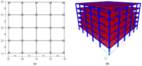
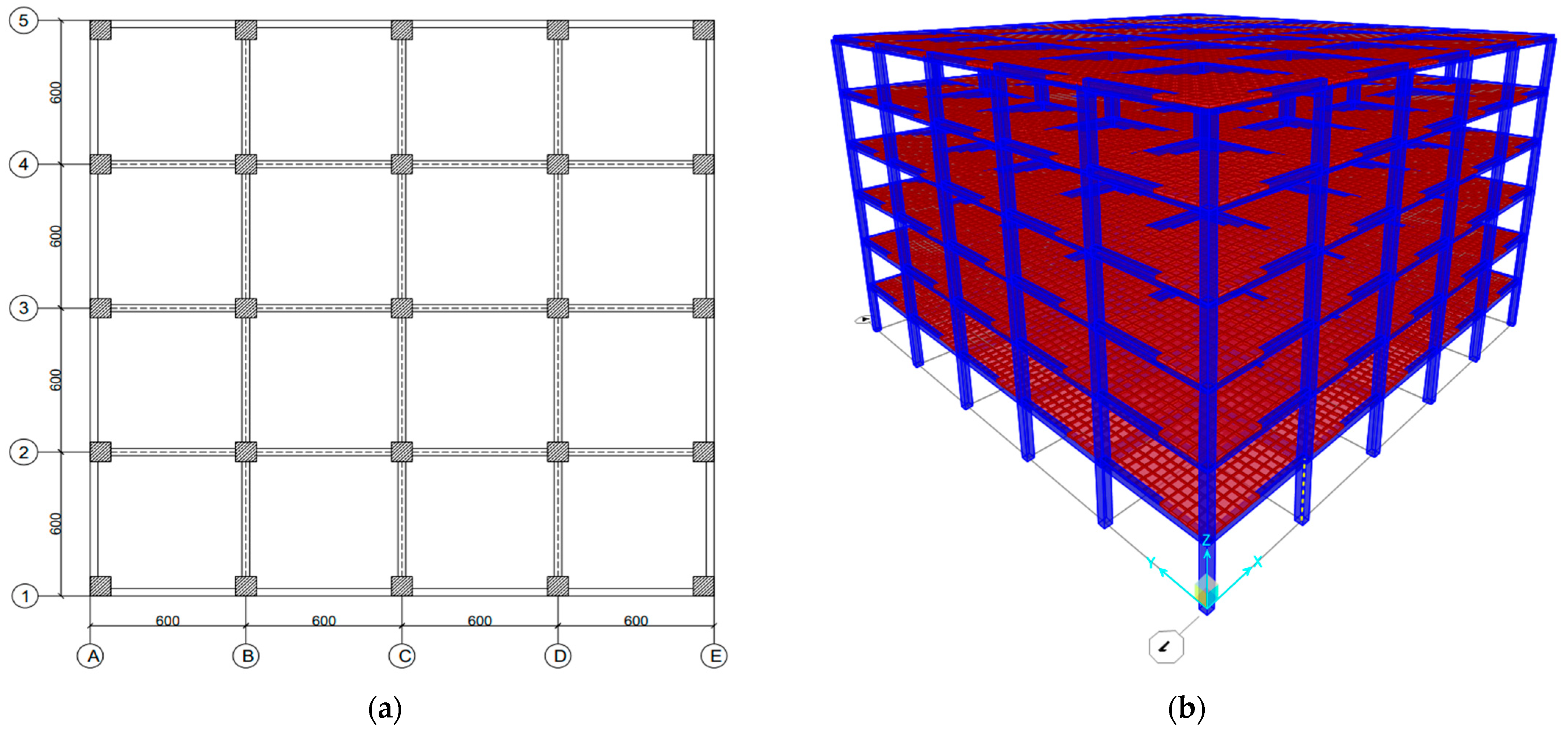
For example, the AFS-R-3 model represents a three-story AFS panel floor model with rigid diaphragm properties. Similarly, the AFS-R-6-Ref model is a six-story AFS-floored reference model with the same column-beam cross-sections. Figure 1 shows the floor plan of the building models and the three-dimensional view of the six-story models. The dimensions in the building model floor plans are in centimeters.
Figure 1.
Floor plan of the building models (a) and three-dimensional views of the 6-story models (b).
In the literature, it is widely accepted that shear walls significantly increase structural stiffness and strength [28,29,30]. However, the main objective of this study is to examine the effect of aluminum foam sandwich (AFS) composite slabs on structural and seismic performance in an isolated manner, eliminating the influence of other dominant stiffness elements. Therefore, only reinforced concrete moment frames were used as the lateral load-bearing system in the analyses; shear-walled or hybrid systems were excluded from the scope of the study. This approach indicates that the results and conclusions are only valid for frame systems.
There are two main reasons for this modeling approach. First, in shear walled hybrid systems, the dominant contribution of walls to structural stiffness and resistance may obscure subtle differences to be investigated, such as slab type (traditional reinforced concrete or AFS) and diaphragm flexibility. Systems consisting solely of frames have enabled the evaluation of the direct and clear effect of these parameters on global structural responses such as natural vibration period, base shear force, and displacements, thus establishing a transparent and fair basis for comparison between the two slab systems. Reference models (AFS-Ref group) isolate the effect of floor material changes independently of column/beam section changes, increasing the reliability of the comparison. This methodological detail clarifies the effect of the floor type alone on performance, alleviating concerns about the possible impact of different column sizes on the results (see Section 3.2 and Section 3.4). Second, the relevant literature has shown that semi-rigid diaphragm frames exhibit more flexible behavior and have longer natural vibration periods compared to rigid diaphragm systems [26]. The fundamental period values obtained from the developed models are consistent with this finding and support the validity of the adopted modeling strategy. Furthermore, practical engineering constraints were considered, and the scope of the study was limited to mid-rise buildings up to six stories, where frames with continuous moment transfer capacity are commonly used, to prevent exceeding realistic column-beam dimensions.
2.2. Material Properties
2.2.1. Reinforced Concrete
It is assumed that C35/45 class concrete and B500B class ribbed rebar steel are used in all reinforced concrete elements (columns, beams, and C-group slabs). The characteristic compressive strength (fck) of concrete is set to 35 MPa, the modulus of elasticity (Ec) is set to 34 GPa, the Poisson’s ratio (νc) is set to 0.20, the unit weight (γc) is set to 25 kN/m3, and the thermal expansion coefficient (αt) is set to 10−5 (1/°C) [25]. The yield strength (fy) of the reinforcing steel is assumed to be 500 MPa and the modulus of elasticity (Es) is assumed to be 200 GPa [30].
2.2.2. Aluminum Foam Sandwich (AFS) Composite
The slab of AFS models is designed with AFS panels manufactured by Pohltec® Metalfoam GmbH (Cologne, Germany). The AFS panel consists of two sheet metal layers (covering sheets) and an aluminum foam core. The covering sheets are made of 6082 aluminum alloy, and the core is made of AlMg3Si6 foam with a relative density of 0.15. The cladding layers and foam core of the AFS panel are joined together without an adhesive.
Figure 2 shows the AFS panel [11]. Due to their low density and cellular structure, AFS panels have a high strength-to-weight ratio and unique thermal and acoustic properties. Energy efficiency, low life-cycle cost, acoustic damping, and impact energy absorption are among their superior mechanical properties [11,12,13,19,22].
Figure 2.
Aluminum foam sandwich panel adopted by Elettore et al., 2023: (a) sandwich panel, (b) side view, (c) cell structure [11].
The mechanical properties of the layers constituting the AFS panel are summarized in Table 1. The elastic modulus (E), Poisson’s ratio (ν), and density (ρ) values for the cover sheets (Al 6082) are standard values that are widely used in the literature for this alloy. The elastic modulus and density for the foam core (AlMg3Si6) were taken directly from the experimental and numerical study conducted by Raeisi et al. [19] on AFS panels.
Table 1.
Mechanical Properties of Aluminum Foam Sandwich (AFS) Panel Layers.
However, the shear modulus of the foam core (Gcore), which determines the semi-rigid behavior of the diaphragm and is a critical parameter for in-plane stiffness, was not reported in the aforementioned study. This deficiency was addressed by referring to the fundamental literature [31,32] describing the micro-mechanical behavior of closed-cell metallic foams. Based on these sources, the shear modulus was calculated to be approximately 1.83 GPa using the Gcore ≈ (3/8) Ecore approach [31,32], which is consistent with Gibson-Ashby-type relationships. The shear modulus of the cover sheets (Al 6082) was calculated using the classical elasticity relationship G = E/[2(1 + ν)] ≈ 26.32 GPa under the assumption of isotropic material.
These adopted material parameters allowed for the use of layered shell elements to represent heterogeneous and anisotropic behavior in the finite element model. This approach separately defines the contribution of the coating and core layers to the in-plane and out-of-plane stiffnesses of the floor, enabling a more realistic numerical representation of AFS flooring, particularly its in-plane shear stiffness, which is the key determinant of semi-rigid diaphragm behavior. The accuracy of the model used has been verified through validation studies based on fundamental mechanical principles presented in Appendix A (see Equations (A1)–(A6) for stiffness calculations and (A7)–(A9) for buckling assessment).
2.3. Design Approach and Ensuring Fair Comparison
In this study, a consistent and serviceability-based design protocol was applied for all models to ensure the comparability of traditional reinforced concrete slab systems (C models) with AFS composite floor systems (AFS-R and AFS-SR models). A deformation-based section determination strategy was adopted to ensure that each system retains its true behavior. In this context, dimensioning was performed according to the following Eurocode-based criteria.
2.3.1. Serviceability Limit State (SLS) Displacement Limits for Slabs
According to Eurocode, the instantaneous and long-term deflection limits for slabs are, respectively [30]:
- Instantaneous deflection limit: L/250;
- Long-term deflection limit: L/500.
Creep and shrinkage effects in reinforced concrete slabs have been included in the long-term calculation; in AFS slabs, long-term deformation is negligible [25].
Both slab types have been iteratively dimensioned to meet these limits, and the final deflection values obtained are presented in Table 2. Both RC and AFS floors meet the serviceability conditions by keeping their immediate and long-term deflections below the relevant limits.
Table 2.
Maximum calculated deflections for a 6.0 m span under service loads.
2.3.2. Lateral Deformation Criteria for Structural Frame Elements
In each model, beam and column sections were determined to meet the following Eurocode 8 criteria [26]:
- Relative story drift limit: θ ≤ 0.005 for SLS;
- Stability factor for second-order effects: θ ≤ 0.10.
The sections were increased until these limit conditions were met, preventing the creation of excessive rigidity.
2.3.3. The Most Economical Section Approach
For each structural configuration, the smallest beam and column sections satisfying both slab deflection limits and lateral deformation criteria were selected. This approach ensured that:
- Artificial stiffness was not added to the systems;
- Differences in global response were governed solely by slab type and diaphragm stiffness;
- The comparison remained objective, transparent, and scientifically consistent.
This design philosophy is a widely used approach in the literature for studies aiming to isolate the effect of floor mass and diaphragm stiffness on global seismic behavior [33,34,35].
It should be noted that thisoptimization has allowed the column and beam sections to be reduced in the AFS models (AFS-R and AFS-SR) due to mass reduction. In contrast, in the AFS-Ref reference models created to show the effect of the floor system more clearly, traditional reinforced concrete floors were replaced with AFS composite floors (in terms of material and section); the frame element (column/beam) section dimensions of the corresponding Traditional (C) models were kept unchanged.
2.4. Section Properties and Loadings
Element dimensions were determined such that slab and beam deflections, effective inter-story drifts, and second-order effects remain within the specified limits. The RC slabs were modeled with a thickness of 15 cm, while AFS composite slabs were modeled with a thickness of 11 cm. Beam sections were kept constant at 25 cm × 40 cm across all models. Column sections were iteratively sized to satisfy Eurocode 8 inter-story drift limits (SLS: θ ≤ 0.005) and stability coefficient for second-order effects (θ ≤ 0.10) [26]. In this process,
- The C models (traditional RC slabs) and AFS-R and AFS-SR models were designed to maintain comparable global displacement capacity. Column sections in the AFS-R and AFS-SR models are identical and were optimized to achieve mass reduction.
- Reference models (AFS-R-1-Ref, AFS-R-6-Ref, AFS-SR-1-Ref, AFS-SR-6-Ref) designed specifically to isolate the effect of the slab system (material and thickness) only were employed. In these models, column and beam sections were kept identical to those of the corresponding traditional (C) models, with no changes applied. This allowed for the isolated observation of the slab type effect alone.
This distinction enables the interpretation of results to clearly attribute differences to slab type and diaphragm rigidity, independent of variations in frame member sizes. The column dimensions are summarized in Table 3.
Table 3.
Column dimensions.
Structural loads were defined in accordance with Eurocode recommendations [36]. Linear loads of 4 kN/m and 3 kN/m were applied to exterior walls and interior partitions, respectively. For standard floor slabs, dead load and live load were both set to 2 kN/m2, while roof slabs were assigned dead and live loads of 1.5 kN/m2. These load values were applied identically to the AFS slab models, i.e., no modifications were made to the superimposed loads other than the inherent weight reduction in the AFS slabs themselves. All columns were fixed at the ground, and soil class B was assumed. Seismic load combinations recommended by Eurocode were considered [36].
2.5. Finite Element Model and Analysis Details
All structural models were created and analyzed using the SAP2000 finite element program [27]. Beams and columns were modeled as frame elements, while slabs were modeled as shell elements. The connection between the slab (shell) elements and the supporting beams (frame elements) was perfectly bound to ensure full composite action and force transfer. AFS panels were represented using the layered shell model developed in this study, which directly reflects the composite sandwich structure (details provided in Section 2.2.2). Unlike a homogeneous isotropic shell assumption, this model is a multi-layered shell element that separately defines the upper and lower aluminum cover sheets and the aluminum foam core, each with its own mechanical properties (E, ν, ρ, G). This approach captures the realistic contribution of each layer to the in-plane and out-of-plane stiffnesses of the panel, ensuring an accurate representation of the in-plane shear stiffness—which is specifically governed by the shear modulus of the foam core (Gcore)—which is the key determinant of semi-rigid diaphragm behavior. The accuracy of the adopted finite element model in simulating the fundamental mechanical behavior of the AFS panel was confirmed by the verification study based on fundamental mechanical principles presented in Appendix A. This validation confirms that it demonstrates sufficient accuracy for global structural performance (diaphragm behavior, mass reduction, and natural periods) and that the in-plane shear stiffness is also represented at an acceptable level.
The rigid diaphragm effect was provided by assigning the relevant diaphragm constraint to the shell nodes. For semi-rigid diaphragm behavior, no diaphragm constraint was assigned, allowing the entire in-plane stiffness of the slab to develop through the membrane stiffness of the layered shell model (specifically defined by the shear modulus of the foam core, Gcore).
A finite element mesh of approximately 0.25 m × 0.25 m was used for the shell elements, and preliminary tests confirmed that the influence of mesh size on the global results was negligible.
In accordance with Eurocode 8 [26], the following load combination was primarily used in response spectrum analysis to evaluate seismic effects: G + ψ2Q ± E. Here, G represents permanent loads (dead load and fixed cladding load), Q represents variable live loads, E represents the seismic effect defined by the design spectrum, and ψ2 is the combination factor for quasi-permanent values, which was set to 0.3 for live loads as specified in the code for residential uses.
The dynamic response of the structures was determined using Response Spectrum Analysis with a design spectrum defined in accordance with Eurocode 8 [26]. In accordance with EN 1998-1 requirements, the elastic design acceleration spectrum used in SAP2000 analyses corresponds to a standard 5% damping ratio (ξ = 5%) [27]. Furthermore, no damping correction factor has been applied to the spectrum. All analyses were performed under the assumption of linear elastic behavior. Therefore, the findings and comparisons of this study are limited to the performance of structures at the elastic demand level; nonlinear behavior, ductility, and performance under strong earthquakes were not been assessed. The scope of the study is limited to medium-rise buildings up to six stories, where frames with continuous moment transfer capacity are commonly used. Seismic loading was defined using Ground Class B, a design site acceleration (ag) of 0.158 g, and a behavior factor (q) of 4.0, which is consistent with regional design practices for ductile reinforced concrete frames and was based on the earthquake hazard in Gümüşhane Province, Turkey. Response spectrum analysis was performed using SAP2000 v26, and a sufficient number of modes were combined to ensure more than 90% mass participation in both directions [26,27].
2.6. Verification of the AFS Panel Modeling Approach for Diaphragm Action
The AFS slab’s in-plane behavior, critical for simulating semi-rigid diaphragm action, depends on its axial and shear stiffness. Modeling the detailed sandwich microstructure in global building analyses is computationally prohibitive. Therefore, an equivalent layered shell model with smeared properties was adopted, as described in Section 2.2.2. To ensure this simplification adequately captures the key in-plane mechanical behavior for global seismic response comparisons, a fundamental verification study was conducted on an isolated AFS panel.
The verification focused on two primary in-plane actions: axial stretching and shear deformation, which govern the diaphragm’s in-plane stiffness. Numerical results from the finite element model were compared against analytical solutions based on classical composite theory using the material properties in Table 1.
- Axial Stiffness (EA): The numerical axial deformation under a unit load differed by less than 1% from the theoretical value, confirming excellent accuracy in representing in-plane axial rigidity.
- Shear Stiffness (GA): The numerical shear deformation was approximately 13% higher than the theoretical estimate. This discrepancy is expected and aligns with the 10–20% range reported in the literature for foam-core sandwiches [37,38], as the simplified analytical model does not fully capture all shear interaction mechanisms. Crucially, the model captures the correct order of magnitude of the relatively low shear stiffness intrinsic to foam-core panels.
This verification confirms that the adopted modeling strategy provides a mechanically consistent and sufficiently accurate representation of the AFS panel’s in-plane stiffness for the purpose of this study: a comparative assessment of global seismic demands between traditional and AFS floor systems under both rigid and semi-rigid diaphragm assumptions. The complete verification procedure, including an assessment of out-of-plane buckling safety under seismic-induced diagonal compression, is detailed in Appendix A.
3. Results and Discussion
This section presents a comparative assessment of the seismic performance of reinforced concrete (C) and aluminum foam sandwich (AFS) slab systems under different diaphragm assumptions and structure heights.
3.1. Comparison of Total Structural Weights
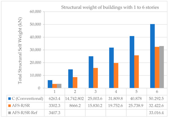
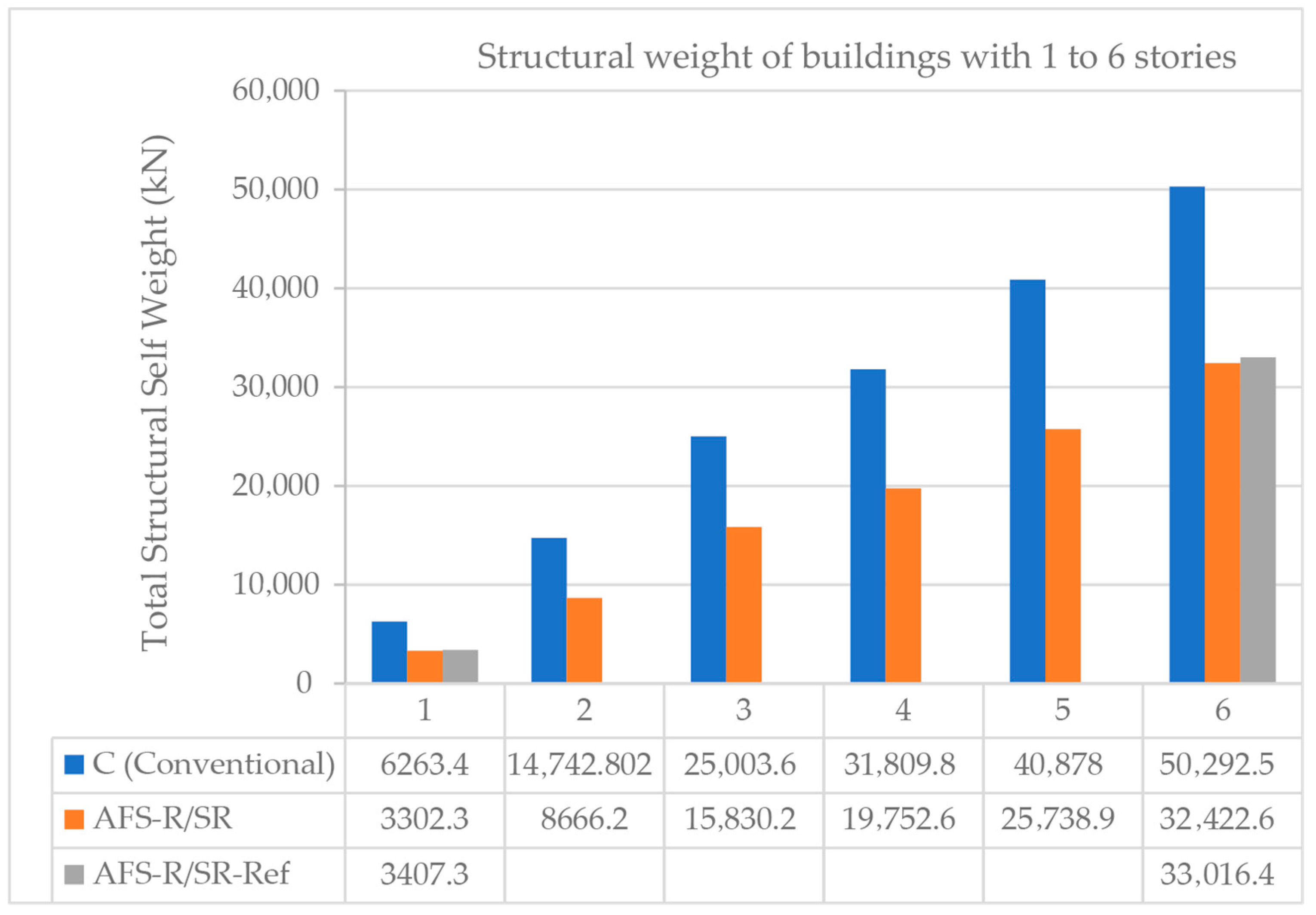
Structural weight is one of the most important parameters directly determining seismic forces. The total structural weights calculated for all models are presented in Table 4 and Figure 3 as a function of the number of stories.
Table 4.
Total structural weights (kN).
Figure 3.
Comparative distribution of total structural weight versus the number of stories for different structural models.
The analysis results show that aluminum foam sandwich (AFS) composite floor systems provide a significant reduction in total building weight compared to traditional reinforced concrete (C) systems. This reduction has been consistently observed at all floor levels. For example, in the optimized 6-story model, the weight of the C-6 model is 50,292.5 kN, while the weight of the AFS-R-6 model is calculated to be 32,422.6 kN. This corresponds to a weight reduction of approximately 35.5% in optimized AFS systems (Table 3). The weight reduction rate reaches up to 47.3% in single-story buildings and stabilizes in the 35.5–37.9% range with increasing number of stories.
The results of the reference models (AFS-Ref) created to isolate the sole effect of the slab system, clarify the sources of weight reduction. In the AFS-Ref models, where the column/beam sections were kept the same as the C models, significant weight reduction was achieved solely by changing the slab material from reinforced concrete to AFS. For example, the AFS-R-6-Ref model, corresponding to the C-6 model, is 34.4% lighter (50,292.5 kN to 33,016.4 kN), while the AFS-R-1-Ref model, corresponding to the C-1 model, is 45.6% lighter (6263.4 kN to 3407.3 kN) (Table 3). This demonstrates that the change in the slab system alone provides a weight advantage in the range of 34.4–45.6%. The additional reduction observed in the optimized AFS-R-6 model represents the supplementary contribution of the optimization of the column sections to this fundamental advantage. This comparison clearly shows that the major and direct component of the total weight reduction originates from the slab system.
The analysis results show that the weight reduction advantage provided by AFS slabs varies with the number of stories. The highest relative advantage is observed in single-story buildings (47.3%), while this ratio decreases with an increasing number of stories and stabilizes in the 35.5–37.9% range for 4–6 story buildings (Table 3). The main reason for this trend is the change in the contribution ratios of the components within the total structural weight. In low-rise buildings, the ratio of slab weight to total weight is relatively higher. Therefore, the effect of switching to a lightweight slab system (AFS) on the total weight is much more pronounced. In high-rise buildings, however, the weight share of vertical structural elements such as columns and shear walls increases. Consequently, the same slab lightening reflects as a smaller percentage of the total weight. However, the absolute weight reduction (in kN) is much greater in high-rise buildings and significantly reduces the absolute values of seismic forces.
It should also be noted that the weights of the AFS-R and AFS-SR models are the same; this confirms that the source of the weight reduction is not the modeling of the diaphragm but the slab material itself.
Consequently, the much lower unit volume weight of AFS composite slabs compared to reinforced concrete [19,25] has resulted in a significant total mass reduction consistently observed in all structural models. Since seismic forces are directly proportional to the total mass of the structure [1], this weight reduction observed in AFS systems is seen to result in lower seismic loads at the linear elastic demand level.
3.2. Evaluation of the Modal Periods
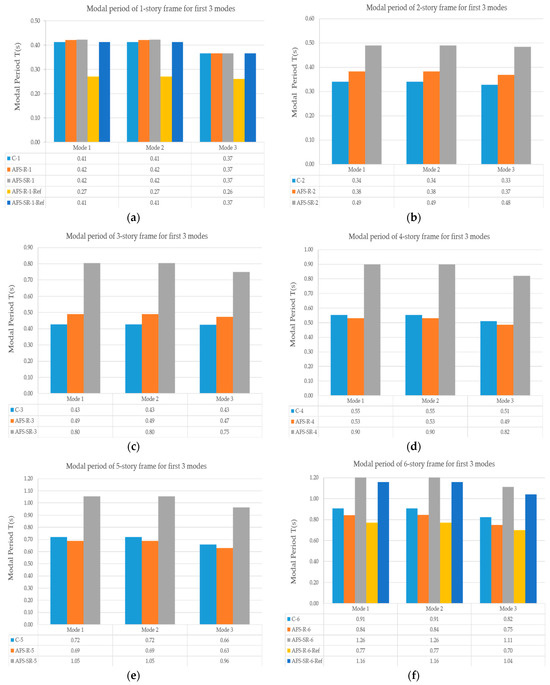
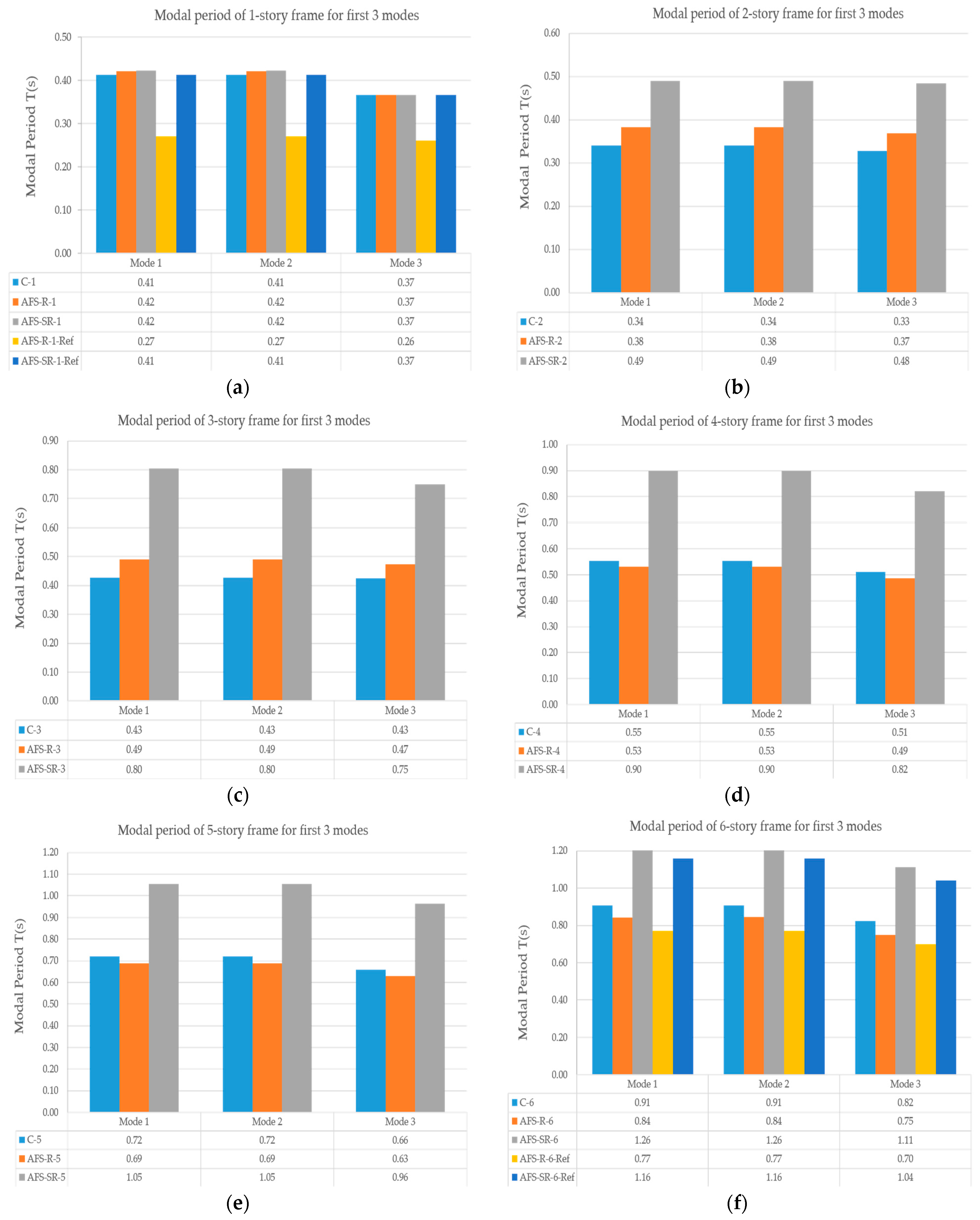
One of the most important parameters determining the dynamic properties of structures, the natural vibration periods, were calculated based on the first three modes for all models and are presented in Figure 4 and Table 5 according to the number of stories. The fact that the obtained fundamental periods are in the range of 0.27–1.19 s confirms the longer period behavior of semi-rigid frames described in the literature [23]. The periods for all model group (C, AFS-R, AFS-SR, AFS-Ref) were analyzed and compared to isolate height, slab system, and diaphragm behavior.
Figure 4.
Modal periods for (a) 1-story, (b) 2-story, (c) 3-story, (d) 4-story, (e) 5-story, and (f) 6-story frames for the first 3 modes.
Table 5.
1st, 2nd and 3rd natural periods of the all frames (seconds).
Reference models (AFS-Ref), designed to isolate the effect of the slab system alone, show significant results at different heights. In these models, the column and beam sections were kept the same as the conventional (C) models and only the slab material and section was changed. The period of the AFS-R-1-Ref model (0.27 s) is significantly shorter than that of the C-1 model (0.41 s). Similarly, the period of AFS-R-6-Ref (0.77 s) is shorter than that of C-6 (0.91 s). This clear finding proves that the mass reduction provided by the floor increases the stiffness/mass ratio of the system while the column stiffness remains constant, and significantly shortens the periods. The effect of diaphragm flexibility varies with height. In a single-story structure, the AFS-SR-1-Ref period (0.41 s) is the same as C-1, suggesting that the effect of diaphragm flexibility on global behavior may be limited in low-rise structures. However, in a 6-story structure, the situation changes significantly: the AFS-SR-6-Ref period (1.16 s) is much longer than both C-6 (0.91 s) and AFS-R-6-Ref (0.77 s). This demonstrates that in high-rise buildings, the low in-plane shear stiffness (semi-rigid behavior) of AFS slabs greatly increases the global flexibility and period of the structure.
In optimized AFS models (AFS-R and AFS-SR), which represent a real design scenario, the combined effects of slab lightening, column optimization, and diaphragm flexibility can be observed. In AFS-R models, the period-shortening effect of slab lightening interacts with the period-increasing effect due to reduced stiffness from smaller column sections. In low-rise models (1–3 stories), the periods are very close to those of the C models (e.g., AFS-R-1: 0.41 s, C-1: 0.41 s) and are even slightly longer in AFS-R-3 (0.48 s) than in C-3 (0.43 s). This indicates that, despite the slab lightening, the minimum section constraints imposed by design codes limit column optimization in low-rise structures and, consequently, period variation. The periods of the AFS-R models at medium height (4–6 stories) are clearly shorter than those of the C models (e.g., AFS-R-6: 0.80 s, C-6: 0.91 s). As the number of stories increases, greater flexibility in section optimization is achieved, thus making the period-shortening effect of mass reduction more pronounced. This demonstrates that AFS systems can provide an improvement in effective stiffness/mass ratio.
The natural vibration period results reveal a fundamental characteristic of the AFS-R systems: despite a significant reduction in mass, their periods are comparable to or even slightly shorter than those of the heavier traditional (C) models, particularly in mid-rise buildings (4–6 stories). This indicates a substantial improvement in the effective stiffness-to-mass ratio of the AFS-R system. It is crucial to clarify that this does not imply a higher absolute global stiffness compared to the traditional RC frame. The observed period shortening stems from the interplay of two factors: the dominant effect of drastic mass reduction (m) and a secondary reduction in absolute lateral stiffness (k) due to column optimization. Within the design constraints of this study, the reduction in seismic mass outweighs the effect of reduced stiffness, leading to a net increase in the ratio k/m and consequently to similar or shorter periods (since T ∝ √ (m/k)). The reference models (AFS-Ref), where column sizes were kept constant further isolate and confirm this mass-driven effect on the period.
In AFS-SR models, the strong period-lengthening effect of the semi-rigid diaphragm combines with the effect of column optimization. As a result, much longer periods are obtained at all floor levels, especially from the 3rd floor onwards, compared to the C and AFS-R models (e.g., AFS-SR-6: 1.19 s, C-6: 0.91 s). On the other hand, despite the increased flexibility, the floor deflections obtained in the AFS-SR models remained within the serviceability limits defined by Eurocode; the relative story drifts and second-order (P–Δ) effects also did not exceed the relevant code limits. This situation demonstrates that systems designed with semi-rigid AFS floors can meet both vertical and horizontal serviceability and stability requirements, despite exhibiting a more flexible global behavior.
The significant period elongation observed in AFS-SR models may indicate a potential reduction in spectral acceleration and base shear forces calculated within the framework of linear elastic analysis, in the context of the European Seismic Code (Eurocode 8) elastic design spectrum. However, the scope of this study is limited to linear elastic analysis. The effects of period elongation on the structure’s nonlinear behavior, ductility, energy dissipation capacity, and strong earthquake performance should be further investigated using nonlinear time-domain analyses.
3.3. Evaluation of Story and Base Shear Force (V)
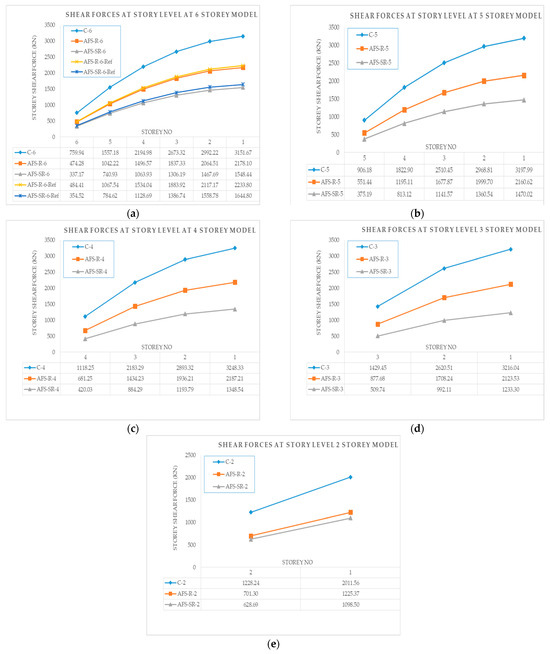
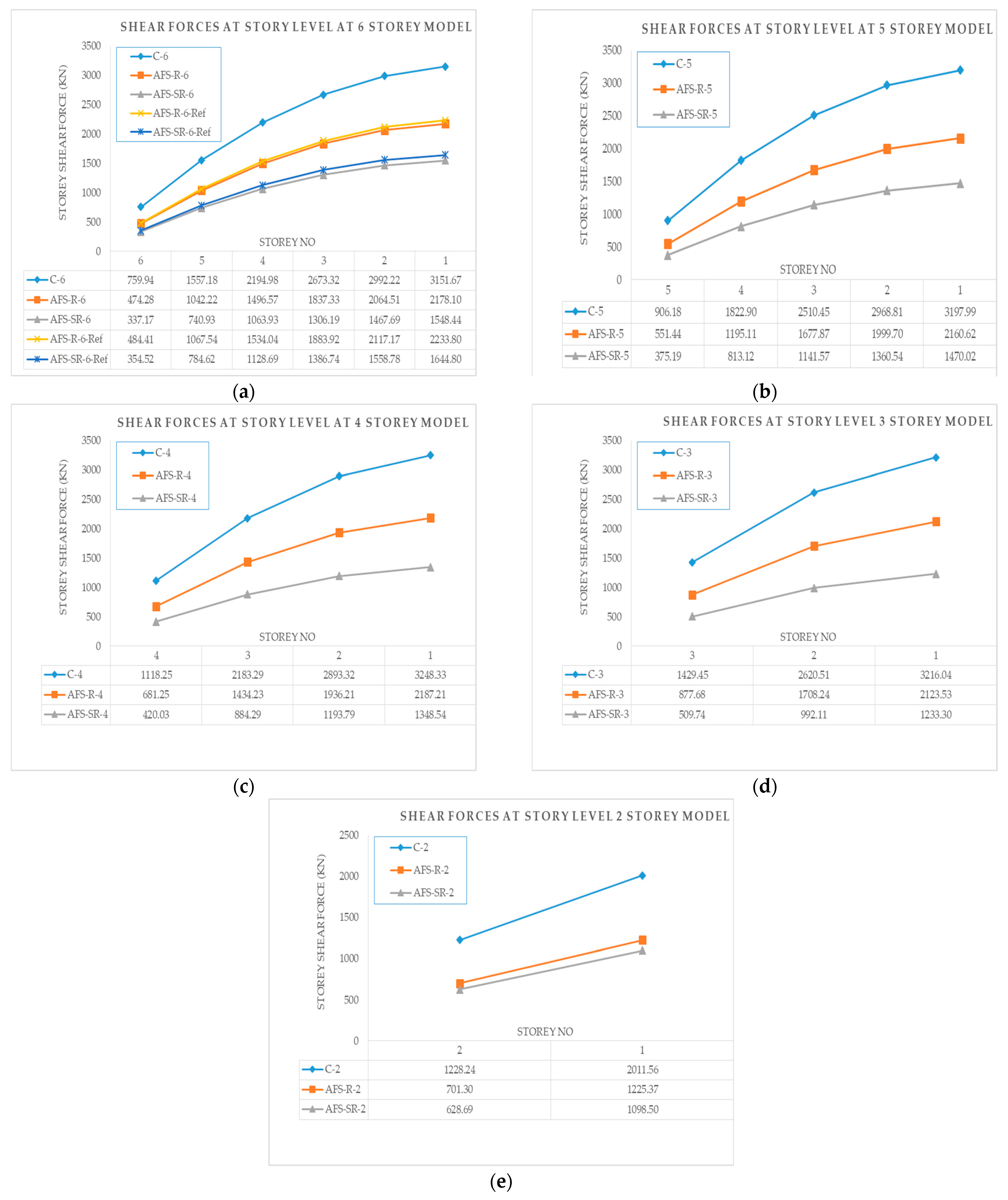
In addition to the base shear force, the story shear forces, which indicate the distribution and magnitude of seismic loads on each story, are of great importance for the design and performance evaluation of structural elements. The calculated floor shear force values for all floor levels are presented comparatively in Table 6, and their variation along the floor height is shown in Figure 5.
Table 6.
Story shear forces (kN) and reduction ratios (%) for all model frames.
Figure 5.
Change in story shear force according to the number of floors in (a) 6-story, (b) 5-story, (c) 4-story, (d) 3-story, (e) 2-story frames.
The analysis of the data presented clearly demonstrates that the advantage provided by Aluminum Foam Sandwich (AFS) slab systems extends to all floors of the structure. Even in the optimized AFS-R models with rigid diaphragms, a reduction in floor shear forces of between 30.9% (6-story, ground floor) and 45.1% (1-story) was observed compared to traditional reinforced concrete (C) models (Table 5). The results of the reference models (AFS-Ref) can be used to identify the sources of this reduction. For example, in the base floor of the 6-story building, the AFS-R-6-Ref model, where only the floor slab was changed, achieved a 29.1% reduction in shear forces, while the AFS-R-6 model, where both the floor slab and columns were optimized, achieved a 30.9% reduction. This comparison confirms that the majority of the total reduction stems directly from the floor lightening, with a smaller portion resulting from secondary column optimization.
However, in semi-rigid diaphragm models (AFS-SR), these reduction rates become much more pronounced due to the additional effect of period elongation discussed in Section 3.2. In three-story and taller buildings (3–6 stories), the floor shear forces in optimized AFS-SR models are 50.9% to 64.3% lower than in traditional C models. The reduction in reference models (e.g., AFS-SR-6-Ref: 47.8%) is slightly lower but still significant, demonstrating that semi-rigid diaphragm behavior alone can reduce shear forces by approximately half. The relatively higher shear force reduction rates observed in upper stories can be attributed to the redistribution of structural load demands in the vertical direction due to mass distribution and mode shapes in lightweight systems. This indicates that the seismic demand reduction achieved with AFS systems is evident not only at the base level but also in shear force demands across all stories.
However, the results obtained in this study have been evaluated within the framework of linear elastic analysis and do not allow the observed shear force reduction to be interpreted as a direct reduction in design sections without considering capacity design principles, element ductility, and local section details. Such reliable results should be supported by element-based nonlinear analyses and detailed section designs.
Despite this, the findings indicate that AFS floors reduce elastic seismic shear force demands throughout the structure and that this effect is distributed consistently between floors, highlighting the potential benefits of lightweight and semi-rigid floor systems at the elastic performance level.
3.4. Evaluation of Maximum Displacement and Inter-Story Drift
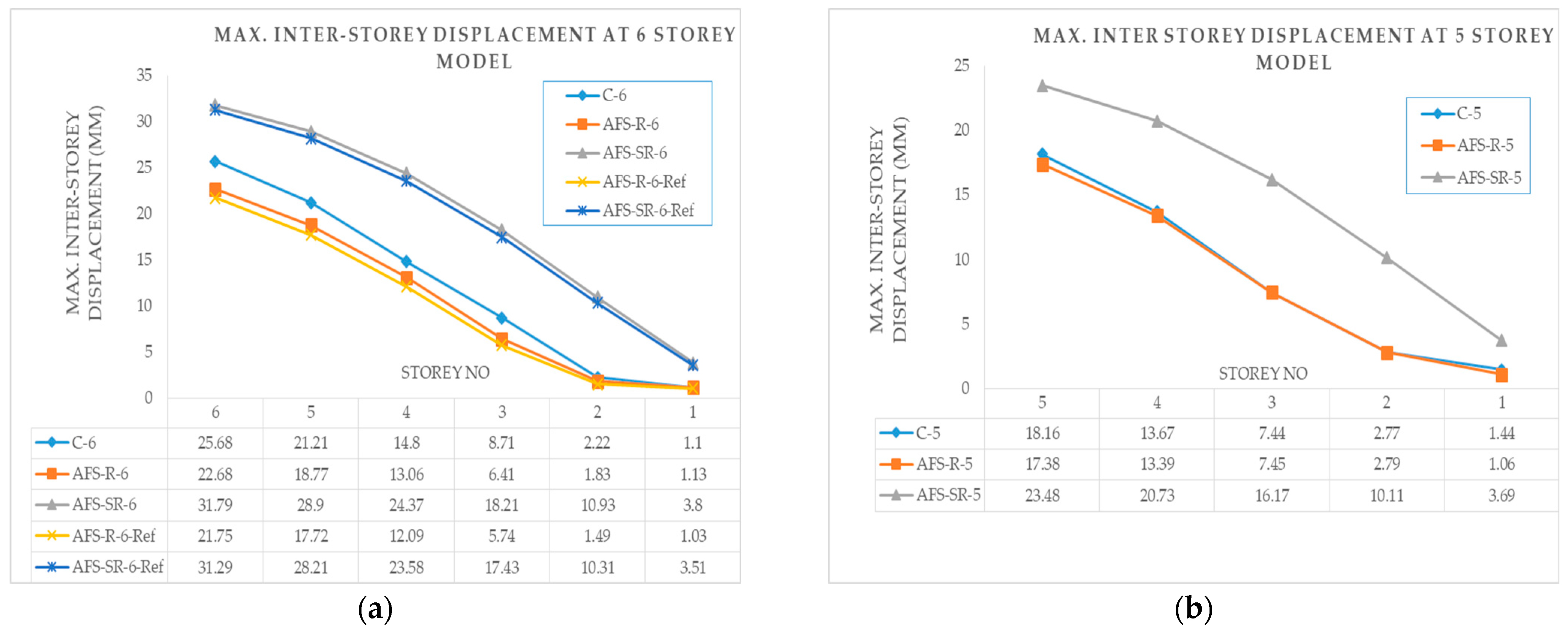
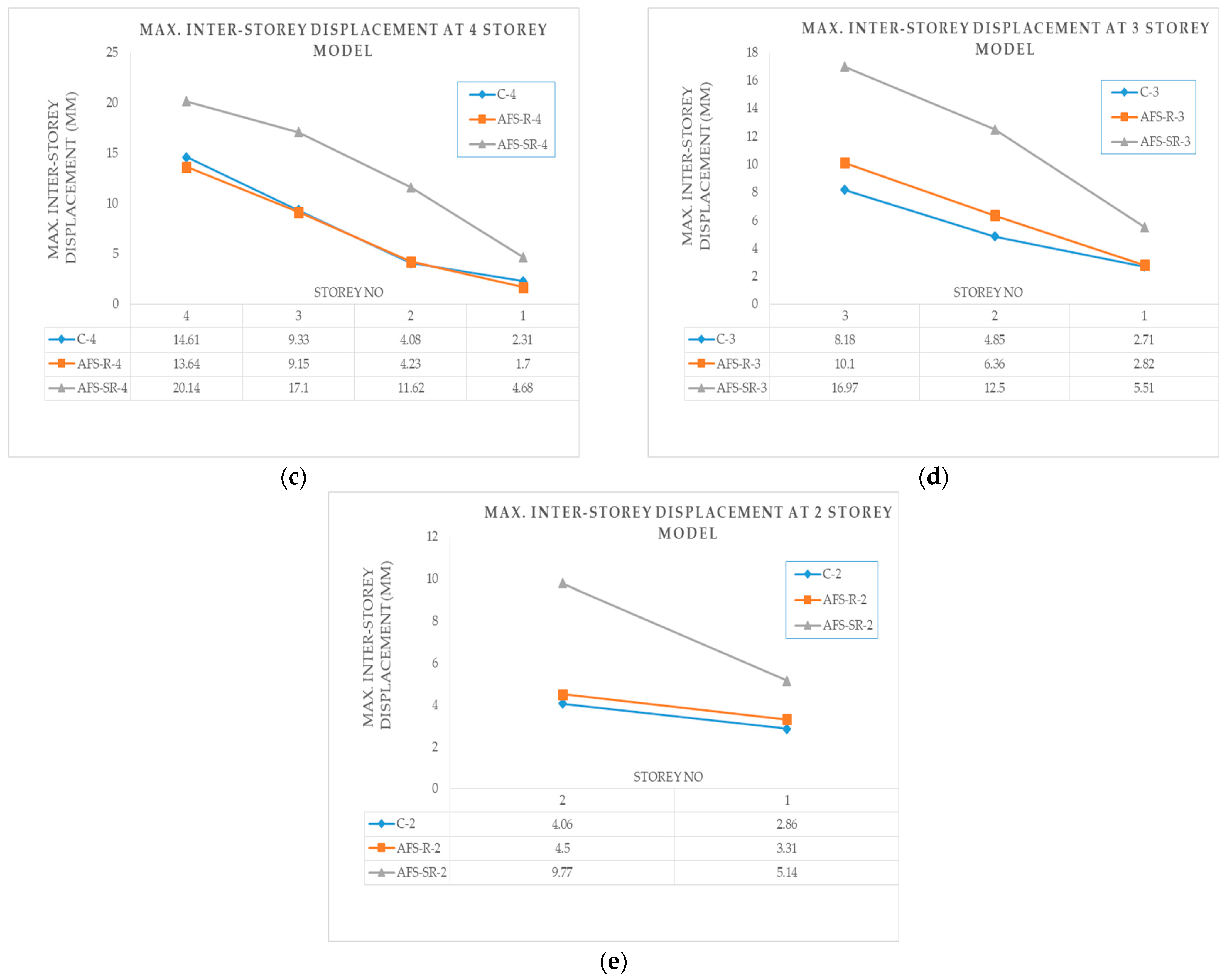
The maximum displacement (dmax) and relative story drift (dr), which are critical parameters determining the service limit state (SLS) performance of structures, have been calculated for all model groups and are presented in Table 7 and Figure 6. In this section, the effects of story count, slab system, diaphragm behavior, and column optimization on these parameters are described in detail.
Table 7.
Maximum displacement (mm) and effective inter-story drift (mm).
Figure 6.
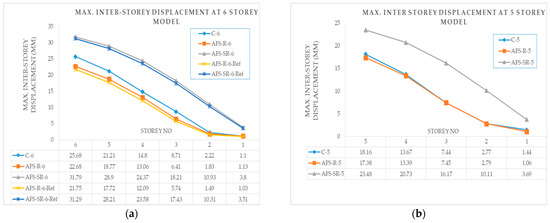
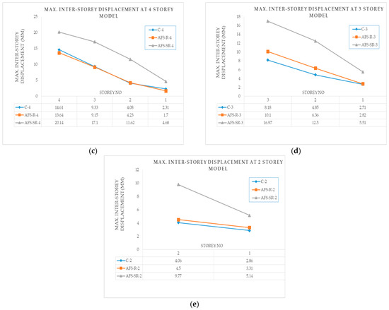
Maximum inter-story displacement variation by story level in (a) 6-story, (b) 5-story, (c) 4-story, (d) 3-story, and (e) 2-story frames.
In optimized AFS models representing real designs, the combined effects of floor lightening, column optimization, and diaphragm behavior are observed. The behavior can be examined in two different regimes depending on the building height.
Low-Rise Building Structures (1–3 Stories): In these structures, traditional C systems exhibit the lowest displacement values. The displacements of rigid diaphragm AFS-R models are very close to or slightly higher than C models (e.g., for 3 stories, AFS-R-3: 10.10 mm; C-3: 8.18 mm). This situation shows that the force reduction provided by slab lightening is partially offset by the effect of column optimization (decreased stiffness), which is limited due to minimum section constraints in low-rise structures. The semi-rigid diaphragm AFS-SR models, as expected, have the highest displacement values.
Mid-Rise Structures (4–6 Stories): The behavior changes in this height range. Rigid diaphragm AFS-R models exhibit lower roof displacement than conventional C systems (e.g., for 6 stories, AFS-R-6: 22.68 mm; C-6: 25.68 mm). This important finding proves that, thanks to the additional flexibility provided by column optimization with increasing number of stories, the reduction in seismic forces provided by floor lightening outweighs the displacement-increasing effect of reduced stiffness, ultimately resulting in a lower elastic displacement demand. This finding demonstrates that, for mid-rise buildings, the reduction in seismic forces due to mass lightening outweighs the displacement-amplifying effect of the reduced lateral stiffness from column optimization, leading to a net decrease in elastic displacement demand. This mechanistic behavior can be explained by the fundamental interplay between mass, stiffness, and spectral response. The substantial mass reduction in AFS-R systems directly lowers the inertial seismic forces (V). While the optimized, smaller columns result in a lower absolute lateral stiffness (k), the demand-side force reduction becomes the dominant factor in the elastic displacement equation (δ ≈ V/k). Consequently, the AFS-R system achieves a lower roof displacement despite its reduced stiffness. This underscores a key seismic advantage of lightweight structural systems within the elastic design spectrum: the benefit of reduced inertia can overcome the penalty of reduced stiffness.
The semi-rigid diaphragm AFS-SR models, on the other hand, always exhibit the highest displacement values due to the dominant effect of diaphragm flexibility. When examining the relative story drift (dr) distribution, it is observed that drift is generally concentrated in the lower-middle stories in AFS-SR models, while C and AFS-R models exhibit a more uniform distribution. This reflects the effect of the semi-rigid diaphragm on mode shapes and internal force distribution.
All analyzed models satisfied the Eurocode 8 serviceability and stability criteria regarding both inter-story drift (dr ≤ 0.005 h) and the second-order effect stability factor (θ ≤ 0.10). This indicates that all systems studied satisfy the serviceability and stability requirements under the assumption of linear elastic behavior.
However, the scope of this study is limited to linear elastic analysis. The effects of the observed displacement differences and distributions on the nonlinear behavior of the structure, plastic hinge formation, energy dissipation capacity, and actual performance under strong earthquakes should be further investigated using nonlinear time-history analyses.
3.5. Evaluation of Column Axial Loads
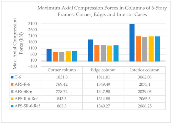
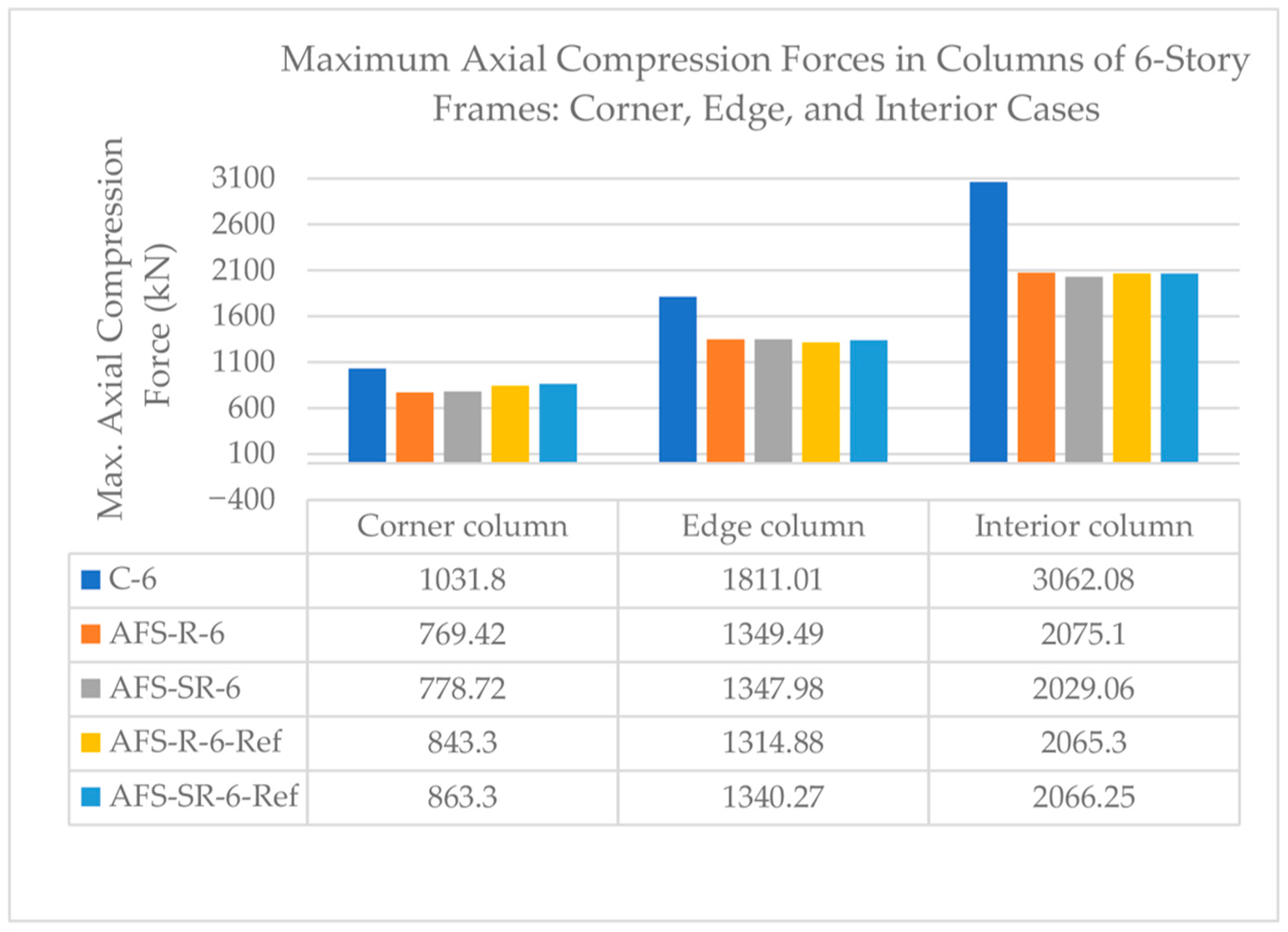
Axial loads in columns are one of the most direct indicators of the effect of the slab system on structural mass and, consequently, on vertical loading. The axial loads in the ground-floor corner, edge, and interior columns of the six-story models are presented in Table 8 and Figure 7.
Table 8.
Maximum Axial Compression Loads (kN) and Reduction Ratios in Ground Floor Columns for 6-Story Models.
Figure 7.
Axial loads on the ground columns of 6-story models.
The reference model (AFS-Ref) results in Table 7 clearly reveal the direct and substantial impact of changing only the slab material (column sections fixed) on axial loads. For instance, the axial load in the interior column decreased by 32.6% in the AFS-R-6-Ref model. This is definitive proof that lightweighting in the slab system directly reduces the structural dead load and, consequently, the vertical load transferred to the columns. The lower reduction ratio in corner columns (16.3–18.3%) can be explained by the fact that a large portion of the load carried by these columns stems from their self-weight and cladding loads.
In the optimized AFS models (AFS-R-6 and AFS-SR-6), there is an additional effect from the reduction in column sections alongside slab lightweighting. The fact that the axial load reduction in the interior column varies between 32.5% and 32.6% in the reference models (AFS-SR-6-Ref and AFS-R-6-Ref, respectively) and reaches 32.2% and 33.7% in the optimized models (AFS-R-6 and AFS-SR-6, respectively) shows that the majority of the total reduction still originates from the slab system, with the additional contribution of column optimization being marginal. The very small differences in axial loads observed between rigid (AFS-R) and semi-rigid (AFS-SR) diaphragm models confirm that diaphragm behavior does not have a determining effect on vertical load distribution within the scope of this study.
The significant axial load reductions obtained indicate a clear potential for reducing section sizes, particularly in interior columns. While this potential is higher in low-rise buildings, in systems consisting solely of moment frames as in this study, horizontal loads (inter-story drift, stability) increasingly govern column design with a greater number of stories. Therefore, the 16.3% reduction in axial load for corner column (and over 32% for interior columns) observed even in the 6-story building reveals that the potential offered by slab lightweighting is constrained by lateral load-resisting requirements.
However, the scope of this study is limited to linear elastic analysis. The full implications of the observed axial load reductions on column buckling capacity, shear capacity in joint regions, capacity design rules, and ultimate foundation design must be assessed separately and considering relevant standards and nonlinear section analyses. In conclusion, AFS slab systems promise potential efficiency gains in structural and geotechnical design by significantly reducing axial loads in columns and, consequently, vertical loading on foundations at the elastic demand level.
4. Conclusions, Limitations, and Future Work
4.1. Conclusions
This study comprehensively compared the effects of aluminum foam sandwich (AFS) composite floor systems against traditional RC beam-slab systems on the seismic performance of reinforced concrete moment frames at the linear elastic demand level. The analyses conducted for 1 to 6-story frame systems yielded the following main conclusions:
Significant Mass Reduction: AFS floors provided a substantial reduction in total structural mass, ranging from 35.5% to 47.3%, compared to traditional RC floors. As demonstrated by the reference models, this reduction originates directly from the lightweight nature of the floor material and section. Since seismic inertial forces are directly proportional to mass, this decrease is the primary reason for the observed reduction in base and story shear forces across all levels.
Dynamic Properties and the Effect of Diaphragm Behavior: The natural vibration periods of AFS systems varied significantly depending on diaphragm assumptions. AFS models with rigid diaphragms (AFS-R) exhibited periods similar to or shorter than those of traditional (C) systems due to the combined effect of mass reduction and column optimization. This indicates an improvement in the effective stiffness-to-seismic-mass ratio for these systems. In semi-rigid diaphragm (AFS-SR) models, a pronounced period elongation (e.g., approximately 31% in the 6-story case) was observed, especially for buildings with 3 or more stories, due to the low in-plane shear stiffness of the floor.
Reduction in Seismic Demand: The mass reduction and period changes led to significant decreases in seismic shear force demands at all story levels. In rigid diaphragm AFS-R models, this reduction ranged from 30.9% to 45.1%, while the addition of semi-rigid diaphragm effects in AFS-SR models increased the reduction rate to higher values between 50.9% and 64.3%. This highlights the potential of lightweight and semi-rigid floor systems to substantially reduce elastic seismic load demands within the framework of linear response spectrum analysis.
Displacement and Story Drift: All models satisfied the Eurocode 8 serviceability and stability criteria (relative story drift ≤ 0.005, stability coefficient θ ≤ 0.10). In mid-rise buildings (4–6 stories), AFS-R systems with rigid diaphragms showed lower maximum displacement demands compared to traditional systems. This is attributed to the reduction in seismic forces from mass loss outweighing the displacement-increasing effect of reduced stiffness from column optimization. Systems with semi-rigid diaphragms, as expected, exhibited higher global displacements.
Reduction in Vertical Loads: The self-weight reduction provided by AFS floors resulted in a notable decrease in maximum axial compression forces in columns. In the 6-story reference models, only changing the floor material led to an up to 32.5% reduction in axial loads for interior columns. This points to a potential for lighter supporting element sections and foundation design loads.
4.2. Study Limitations
The findings of this study should be interpreted within the context of the following methodological boundaries, which also define key directions for future research:
Linear Elastic Analysis Scope: The study employs linear elastic response spectrum analysis. It therefore compares elastic seismic demand parameters (periods, forces, drifts) and does not capture nonlinear material behavior, ductility, or ultimate collapse performance.
Pure Moment Frame Focus: The analysis is limited to moment-resisting frame systems. The interaction of the semi-rigid AFS diaphragms with shear walls in dual systems remains an important topic for future work.
AFS Panel Modeling Simplifications: The global modeling of AFS panels using equivalent shell elements, while validated for in-plane stiffness, does not capture local effects such as face sheet-core interaction, connector details, or local buckling. Additionally, the connection between the AFS panels and the reinforced concrete frame was modeled as perfectly rigid (fully bound) to ensure composite action. The potential effects of connection flexibility, slip, or the detailed mechanical behavior of discrete fasteners on the global structural response were not considered.
Parametric and Practical Boundaries: The conclusions are derived for low- to mid-rise (1–6 story) buildings. Practical implementation details—such as panel joints, fire protection, and integration with building services—were beyond the scope of this numerical study.
4.3. Recommendations for Future Work
In light of the findings of this study, the following topics are recommended for future research:
Nonlinear Time-History Analyses: Conducting nonlinear time-history analyses is crucial to evaluate the real performance of AFS-equipped systems under severe earthquakes, including plastic hinge development, energy dissipation capacity, and collapse mechanisms.
Investigation in Dual (Wall-Frame) Systems: Researching the effect of AFS floors in dual structural systems, where they are used alongside RC shear walls, will broaden the applicability of the findings.
Experimental Validation and Connection Details: Experimental validation of the actual floor behavior, diaphragm action, and connection details of AFS panels to the RC frame through full- or large-scale tests will enhance the reliability of numerical models and contribute to the development of application guidelines.
Economic and Environmental Life-Cycle Analysis: A comprehensive analysis of the potential impacts of the lightness provided by AFS systems on construction costs, foundation dimensions, carbon footprint, and the building’s life-cycle cost will allow for a more holistic assessment of this innovative material’s applicability.
Optimization Studies: Developing multi-objective design optimization algorithms for AFS floor systems, considering parameters such as mass, stiffness, diaphragm flexibility, and material cost, can create guidelines for their most efficient use.
Author Contributions
Conceptualization, Ö.D.; Methodology, Ö.D. and E.Ö.; Software, Ö.D.; Formal analysis, Ö.D.; Data curation, Ö.D.; Writing—original draft, Ö.D.; Writing—review & editing, Ö.D. and E.Ö.; Supervision, E.Ö. All authors have read and agreed to the published version of the manuscript.
Funding
This research received no external funding.
Data Availability Statement
All data are contained within the article.
Conflicts of Interest
The authors declare no conflict of interest.
Appendix A. Numerical Verification of the In-Plane Behaviour of the AFS Panel
The purpose of this experiment is to verify, within the scope of the finite element modeling approach, that the aluminum foam sandwich (AFS) panels used in the main study are mechanically consistent in terms of in-plane axial stiffness, shear stiffness, and out-of-plane elastic buckling safety. Accordingly, one of the AFS panels used in the main study was isolated, and the following three fundamental verification analyses were performed:
- In-plane axial stiffness verification (EA test);
- In-plane shear stiffness verification (GA test);
- Out-of-plane elastic buckling check under diagonal compression (Eigenvalue buckling).
The obtained numerical results were evaluated by comparing them with analytical solutions based on classical sandwich panel theory.
Material Assumptions and Theoretical Basis: The AFS panel consists of two aluminum face sheets and an isotropic, closed-cell aluminum foam core. The panel was modeled in SAP2000 software using the layered composite shell approach.
Geometry:
- Panel dimensions: 6000 mm × 6000 mm;
- Total thickness: 110 mm;
- Bottom aluminum face: 2 mm;
- Aluminum foam core: 106 mm;
- Top aluminum face: 2 mm.
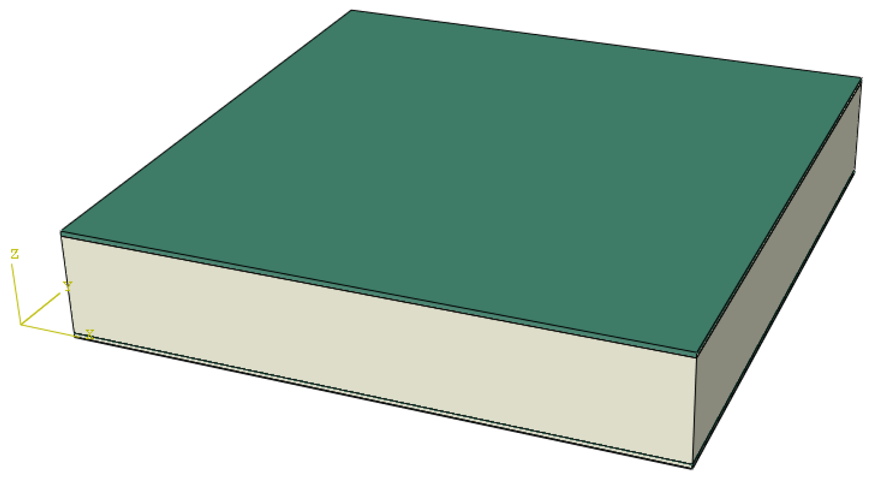
Figure A1 schematically presents the three-dimensional view and layered structure of the AFS panel used in the verification analyses.
Figure A1.
Schematic view of the AFS panel.
Material Properties:
- Aluminum faces (Al 6082):
- Modulus of elasticity: EAl = 70 GPa;
- Poisson’s ratio: νAl = 0.33
- Aluminum foam core:
- Modulus of elasticity: Efoam = 4.89 GPa;
- Poisson’s ratio: νfoam = 0.33.
In the literature, it is stated that for isotropic closed-cell metal foams, the shear modulus is approximately 3/8 of the modulus of elasticity [31,32]. Accordingly,
Gfoam = (3/8) * Efoam
For aluminum faces, the classical relation was used:
GAl = EAl/(2(1 + νAl))
Appendix A.1. In-Plane Axial Stiffness Verification (EA Test)
Theoretical Background: Assuming full composite behavior, the in-plane axial stiffness is calculated as follows:
EA = (∑ Ei·ti)·b
Using this stiffness value, the axial displacement is calculated as:
δEA,theory = N·L/EA
SAP2000 Numerical Model: Boundary conditions were defined in the coordinate system as follows:
- Edge in the X = 0 direction: Ux = Uy = Uz = 0;
- Edge in the X = 6 m direction: Uy = Uz = 0, Ux free.
Reference axial load:
Nref = 7800 kN (Nx = 1300 kN/m);
The load was distributed equally to the nodes on the edge at X = 6 m.
Results:
- Theoretically calculated axial displacement: δEA,theory = 9.77 mm;
- The average axial displacement value obtained from SAP2000 finite element analysis is δEA,FE = 9.80 mm.
The difference between the theoretical and numerical results is below approximately 1%. This shows that the in-plane shear stiffness of the panel is represented with high accuracy by the finite element model.
Appendix A.2. In-Plane Shear Stiffness Verification (GA Test)
Theoretical Background: Assuming full composite behavior, the in-plane axial stiffness is calculated as follows:
GA
= (∑ Gi·ti)·b
Shear deformation is calculated as follows:
δGA,theory
= V·L/GA
SAP2000 Numerical Model:
- Edge in the X = 0 direction: Ux = Uy = 0;
- Edge in the X = 6 m direction: Uy = 0, Ux free.
Reference shear force:
Vref = 7800 kN.
Results:
- Theoretical shear displacement: δGA,theory = 26.0 mm;
- Value obtained from SAP2000 analysis: δGA,FE = 30.1 mm.
The difference between the two results is approximately 13%, which is consistent with the 10–20% range reported in the literature for foam-core sandwich panels [37,38]. This result shows that the model represents the low shear stiffness at the correct order of magnitude.
Appendix A.3. In-Plane Linear Buckling Analysis
Theoretical Background: The objective of the experiment detailed in this section is to numerically verify the buckling safety of the Aluminum Foam Sandwich (AFS) panel under in-plane shear loading. A linear buckling (eigenvalue) analysis determines the critical buckling load as a multiplier of an applied reference load. The fundamental relationship is given by:
where Pcr is the critical buckling load, λcr is the critical load factor (eigenvalue), and Pref is the applied reference load.
Pcr
= λcr·Pref
SAP2000 Numerical Model and Load Case: The analysis was performed using the identical finite element model created for the shear stiffness (GA) verification in Appendix A.2.
- Boundary Conditions: The edge at X = 0 m was restrained: Ux = Uy = 0. The edge at X = 6 m was restrained in the vertical direction (Uy = 0) but left free to move horizontally (Ux free).
- Reference Shear Load: A total reference shear force of Vref = 7800 kN was applied in the +X direction. This load was distributed as point loads of 600 kN to each of the 13 nodes along the edge at X = 6 m. This configuration was defined in a Static load case named A2SHEAR.
- Buckling Analysis Setup: A new load case named BUCKLING was created with its type set to Buckling. The “Buckling Load Case” parameter was set to reference the A2SHEAR load case as the base state. A linear eigenvalue solution was requested for the first three buckling modes.
Results: The linear buckling analysis yielded the critical load factors (λ) for the first three modes, as summarized in Table A1.
Table A1.
Linear buckling analysis results.
The negative value for Mode 2 indicates a similar buckling capacity under shear loading in the opposite direction. For stability assessment, the positive factor of the first mode, possessing the lowest absolute value (λcr = 56.10), is governing. Applying Equation (A7) for shear force yields the critical buckling shear force,
Vcr = λcr × Vref = 56.10 × 7800 kN ≈ 437,850 kN
Safety Assessment: The maximum design-level shear force expected in a single panel under seismic action is derived from the main study results. For the 6-story AFS-R-6-Ref model, the maximum ground story shear force is Vmax = 2233.80 kN (see Section 3.3). Assuming 25 panels per floor, the maximum shear force per panel is:
Vpanel,max = Vmax/25 = 89.35 kN
The buckling safety factor (FS) is then calculated by comparing the critical capacity to the design demand:
FS = Vcr/Vpanel,max = 437,580 kN/89.35 kN ≈ 4897.37
Evaluation: The result FS ≈ 4900 >> 1.0, which unequivocally demonstrates that the AFS panel possesses a very high safety margin against elastic buckling induced by in-plane shear forces within the scope of the seismic loads considered in this study. The panel’s ability to sustain a load approximately 4900 times greater than the maximum expected design shear force before reaching instability provides strong numerical justification. It confirms that potential buckling is not a governing failure mode and validates the stability of the semi-rigid diaphragm modeling approach used in the global structural analyses.
References
- Fardis, M.N. Seismic Design, Assessment and Retrofitting of Concrete Buildings: Based on EN-Eurocode 8; Springer: Dordrecht, The Netherlands, 2009. [Google Scholar]
- Paulay, T.; Priestley, M.J.N. Seismic Design of Reinforced Concrete and Masonry Buildings; John Wiley & Sons: New York, NY, USA, 1992. [Google Scholar]
- Bitzer, T. Honeycomb Technology: Materials, Design, Manufacturing, Applications and Testing; Springer: Dordrecht, The Netherlands, 1997. [Google Scholar]
- Belleri, A.; Riva, P. Seismic performance and retrofit of precast concrete grouted sleeve connections. PCI J. 2012, 57, 97–109. [Google Scholar] [CrossRef] [Scilit]
- Abaza, E.; Elshazli, M.T.; Elbelbisi, A.; Shehab, H.; Zaghlal, M. Punching Strengthening of Lightweight Aggregate Reinforced Concrete Flat Slabs Using Fiber-Reinforced Polymers. J. Compos. Sci. 2025, 9, 485. [Google Scholar] [CrossRef] [Scilit]
- Gibson, L.J. Cellular solids. MRS Bull. 2003, 28, 270–274. [Google Scholar] [CrossRef] [Scilit]
- Birman, V.; Kardomateas, G.A. Review of current trends in research and applications of sandwich structures. Compos. Part B Eng. 2018, 142, 221–240. [Google Scholar] [CrossRef] [Scilit]
- Banhart, J.; Seeliger, H.W. Aluminium foam sandwich panels: Manufacture, metallurgy and applications. Adv. Eng. Mater. 2008, 10, 793–802. [Google Scholar] [CrossRef] [Scilit]
- Crupi, V.; Kara, E.; Epasto, G.; Guglielmino, E.; Aykul, H. Prediction model for the impact response of glass fibre reinforced aluminium foam sandwiches. Int. J. Impact Eng. 2015, 77, 97–107. [Google Scholar] [CrossRef] [Scilit]
- Garcia-Avila, M.; Portanova, M.; Rabiei, A. Ballistic performance of composite metal foams. Compos. Struct. 2015, 125, 202–211. [Google Scholar] [CrossRef] [Scilit]
- Elettore, E.; Latour, M.; D’Aniello, M.; Landolfo, R.; Rizzano, G. Prototype Tests on Screwed Steel–Aluminium Foam–Steel Sandwich Panels. Buildings 2023, 13, 2836. [Google Scholar] [CrossRef] [Scilit]
- Gargano, A.; Das, R.; Mouritz, A.P. Comparative experimental study of the explosive blast response of sandwich used in naval ships. Compos. Commun. 2022, 30, 101072. [Google Scholar] [CrossRef] [Scilit]
- Lu, W.K.; Zhang, J.Y. Mechanical response of aluminum foam sandwich structure under impact loading. Mater. Res. Express 2022, 9, 016515. [Google Scholar] [CrossRef] [Scilit]
- Zhang, Y.; Yin, F.; Ma, J. Experimental and numerical analysis of the impact resistance of polyurethane foam aluminum-concrete sandwich structures. Buildings 2024, 14, 3573. [Google Scholar] [CrossRef] [Scilit]
- Zhang, Y.; Lu, M.; Sun, G.; Li, Q. On functionally graded composite structures for crashworthiness. Compos. Struct. 2015, 132, 393–405. [Google Scholar] [CrossRef] [Scilit]
- Zhang, J.X.; Guo, H.Y. Dynamic response of rectangular sandwich tubes with metal foam core under blast loading. Int. J. Appl. Mech. 2022, 14, 2150126. [Google Scholar] [CrossRef] [Scilit]
- Mondal, D.P.; Goel, M.D.; Das, S. Effect of strain rate on compressive deformation behaviour of closed cell aluminium–fly ash composite foam. Mater. Des. 2009, 30, 1268–1274. [Google Scholar] [CrossRef] [Scilit]
- Evans, A.G.; Hutchinson, J.W.; Fleck, N.A.; Ashby, M.F.; Wadley, H.N.G. The topological design of multifunctional cellular metals. Prog. Mater. Sci. 2001, 46, 309–327. [Google Scholar] [CrossRef] [Scilit]
- Raeisi, S.; Kadkhodapour, J.; Tovar, A. Mechanical properties and energy absorbing capabilities of Z-pinned aluminum foam sandwich. Compos. Struct. 2019, 214, 34–46. [Google Scholar] [CrossRef] [Scilit]
- Liu, Z.; Huang, Z.; Qin, Q. Experimental and theoretical investigations on lateral crushing of aluminum foam-filled circular tubes. Compos. Struct. 2017, 175, 19–27. [Google Scholar] [CrossRef] [Scilit]
- Motz, C.; Pippan, R. Deformation behaviour of closed-cell aluminium foams in tension. Acta Mater. 2001, 49, 2463–2470. [Google Scholar] [CrossRef] [Scilit]
- Taherishargh, M.; Belova, I.V.; Murch, G.E.; Fiedler, T. Low-density expanded perlite–aluminium syntactic foam. Mater. Sci. Eng. A 2014, 604, 127–134. [Google Scholar] [CrossRef] [Scilit]
- Kollerathu, J.A.; Menon, A. Role of diaphragm flexibility modelling in seismic analysis of existing masonry structures. Structures 2017, 11, 22–39. [Google Scholar] [CrossRef] [Scilit]
- Fang, C.H.; Leon, R.T. Seismic behavior of symmetric and asymmetric steel structures with rigid and semirigid diaphragms. J. Struct. Eng. 2018, 144, 04018186. [Google Scholar] [CrossRef] [Scilit]
- EN 1992-1-1:2004; Eurocode 2: Design of Concrete Structures—Part 1-1: General Rules and Rules for Buildings. European Committee for Standardization: Brussels, Belgium, 2004.
- EN 1998-1:2004; Eurocode 8: Design of Structures for Earthquake Resistance—Part 1: General Rules, Seismic Actions and Rules for Buildings. European Committee for Standardization: Brussels, Belgium, 2004.
- Computers & Structures, Inc. SAP2000 Integrated Software for Structural Analysis and Design, Version 26.0.0; Computers & Structures, Inc.: Walnut Creek, CA, USA, 2024.
- Kose, M.M. Parameters affecting the fundamental period of RC buildings with infill walls. Eng. Struct. 2009, 31, 93–102. [Google Scholar] [CrossRef] [Scilit]
- Pandya, P.; Shah, S.; Thakkar, K. Optimizing Column and Shear Wall Ratios for Seismic Performance of High-Rise Reinforced Concrete (RC) Structures: A Parametric Study. In Proceedings of the International Conference on Recent Advances in Structural Engineering, Singapore, 16–17 December 2024; Springer: Singapore, 2024; pp. 47–57. [Google Scholar] [CrossRef] [Scilit]
- EN 10080:2005; Steel for the Reinforcement of Concrete—Weldable Reinforcing Steel—General. European Committee for Standardization: Brussels, Belgium, 2005.
- Gibson, L.J. Mechanical Behavior of Metallic Foams. Annu. Rev. Mater. Sci. 2000, 30, 191–227. [Google Scholar] [CrossRef] [Scilit]
- Kalpakoglou, T.; Yiatros, S. Metal Foams: A Review for Mechanical Properties under Tensile and Shear Stress. Front. Mater. 2022, 9, 998673. [Google Scholar] [CrossRef] [Scilit]
- Benzo, P.G.; Sena-Cruz, J.; Pereira, J.M. A new lightweight floor system based on sandwich panel. In Proceedings of the 10th International Conference on FRP Composites in Civil Engineering (CICE 2020), Istanbul, Türkiye, 1–3 July 2020. [Google Scholar]
- Moroder, D.; Smith, T.; Simonetti, M.; Ponzo, F.C.; Cesare, A.D.; Nigro, D.; Pampanin, S.; Buchanan, A.H. Experimental behaviour of diaphragms in post-tensioned timber frame buildings. In Proceedings of the 2nd European Conference on Earthquake Engineering and Seismology (2ECEES), Istanbul, Turkey, 24–29 August 2014. [Google Scholar]
- Raghuvanshi, L.; Vyas, J.N. Seismic performance of RC structure with and without shear wall using flat slab with huge openings subjected to diaphragm discontinuity—A literature review. Int. J. Res. 2023, 4, 1537–1545. [Google Scholar]
- EN 1991-1-1:2002; Eurocode 1: Actions on Structures—Part 1-1: General Actions—Densities, Self-Weight and Imposed Loads for Buildings. European Committee for Standardization: Brussels, Belgium, 2002.
- Cui, Z.; Wang, Z.; Cao, F. Research on Mechanical Properties of V-Type Folded Core Sandwich Structures. Aerospace 2022, 9, 398. [Google Scholar] [CrossRef] [Scilit]
- Ivañez, I.; Santiuste, C.; Sanchez-Saez, S. FEM Analysis of Dynamic Flexural Behaviour of Composite Sandwich Beams with Foam Core. Compos. Struct. 2010, 92, 2285–2291. [Google Scholar] [CrossRef] [Scilit]



Disclaimer/Publisher’s Note: The statements, opinions and data contained in all publications are solely those of the individual author(s) and contributor(s) and not of MDPI and/or the editor(s). MDPI and/or the editor(s) disclaim responsibility for any injury to people or property resulting from any ideas, methods, instructions or products referred to in the content. |
© 2026 by the authors. Licensee MDPI, Basel, Switzerland. This article is an open access article distributed under the terms and conditions of the Creative Commons Attribution (CC BY) license.