


Abstract
Increasing the share of renewable energies is a key challenge in residential heating systems, particularly when available solar heat cannot be effectively stored or used. This study examines a façade-integrated Multifunctional Building Part (MBP) incorporating a phase change material (PCM), with a hydronic circuit designed for active thermal charging and renewable heat integration. The PCM-enhanced MBP enables direct charging of latent thermal storage through a hydronic circuit and provides an active envelope-based approach for storing renewable heat and supporting space heating. The PCM behaviour was experimentally verified at the component level using the SmallHouse IV demonstrator, and the resulting model was subsequently integrated into the International Energy Agency Solar Heating and Cooling (IEA SHC) Task 32 single-family reference building for seasonal numerical simulations under selected climatic conditions. The building-level assessment considers the conventional reference building, the hydronically activated MBP without PCM, and the PCM-enhanced MBP, thereby distinguishing the overall effect of the MBP from the additional contribution of latent thermal storage. The results demonstrate a progressive improvement in renewable heat utilization and electrical energy performance from the reference building to the hydronically activated MBP and, under favorable climatic conditions, to the PCM-enhanced configuration. In Stuttgart, the MBP reduced electrical energy demand from 1719.7 to 1255.6 kWh, with a further reduction to 962.0 kWh after PCM integration. Correspondingly, solar thermal utilization increased from 1194 kWh for the reference building to 2756 kWh with the MBP and 3999 kWh with PCM. Across Stuttgart, Madrid, and Kabul, the additional PCM integration reduced electrical energy demand by 23–69% and increased solar thermal utilization by 22–45% relative to the MBP without PCM. In contrast, under the investigated Moscow climate, PCM integration increased electrical energy demand by 9.6% and reduced solar thermal utilization by 6.9%, indicating a deterioration in simulated system performance. Overall, the results indicate that the performance of PCM-based thermal storage within the building envelope is highly dependent on the interaction between heating demand, renewable heat availability, and the opportunities for latent heat charging and discharging. The study highlights the potential of component-verified PCM-enhanced and numerically investigated hydronically activated building components for climate-adaptive renewable heat utilization in residential building.
1. Introduction
The energy required to operate buildings represents a substantial component of overall energy demand, with space heating being particularly relevant in cold and temperate climates, which accounts for almost 80% of energy use in temperate European regions [1,2]. Achieving carbon neutrality, as targeted by international agreements, requires integrating both energy-efficient design and renewable technologies [3]. Although technologies such as solar thermal collectors can provide significant renewable heat, a considerable fraction of the available energy often remains unused due to temporal mismatches between renewable heat production and heating demand and the finite capacity of conventional storage systems can prevent the full use of available renewable heat. Increasing the ability of building components to retain this otherwise unused energy therefore represents an important opportunity for improving renewable heat utilization.
Recent studies have demonstrated the potential of integrating renewable energy technologies directly into building envelopes. Gür and Öztop [4] investigated the year-round performance of an integrated PV/T–BIPV system, while Gür et al. [5] experimentally examined the thermal behavior of building-integrated double-skin façades. Furthermore, recent research on grid-connected building microgrids has emphasized that energy performance should be considered alongside broader environmental objectives, including time-dependent carbon emissions [6]. Collectively, these studies highlight recent developments in renewable energy integration and multifunctional building systems.
Thermal storage can address this temporal mismatch by retaining available heat and making it accessible when the building requires it. Among the various thermal storage strategies investigated for buildings, PCMs have emerged as a promising option because their phase transition enables substantial amounts of thermal energy to be absorbed and released within a relatively narrow temperature range. When appropriately selected for the intended operating conditions, this property can moderate temperature fluctuations and shift part of the heating or cooling demand away from periods of peak load [7]. The attributes of PCMs—including their ability to undergo phase transitions at precise, predefined temperatures, their high density of thermal energy storage, and their capability to operate within a range of thermal environments without significant degradation—make them ideal for integration into the building envelope [8]. Existing research suggests that incorporating PCMs into building components can moderate indoor temperature variations and alter the timing of thermal loads. [9,10]. However, the majority of investigated PCM applications rely on passive operation, where charging and discharging are solely driven by ambient conditions and indoor temperature fluctuations.
Although passive PCM systems provide certain benefits, their effectiveness strongly depends on material placement, phase transition temperature, climatic conditions, and indoor temperature set points [11,12]. Several studies have reported that PCM layers located in thermally stable zones of the building envelope experience limited phase transitions and therefore provide only modest energy savings [12]. More importantly, passive PCM concepts generally do not address a fundamental challenge in renewable heating systems: the effective utilization of surplus low-temperature renewable heat. Consequently, PCMs are often employed as passive thermal regulators rather than as active components of a building-scale energy management strategy.
To overcome some of these limitations, active PCM concepts have recently been investigated. For example, Chen et al. [13] introduced a pipe-embedded PCM wall in which hydronic circulation actively interacts with the PCM layer, demonstrating improved envelope performance in cooling-oriented demand-response applications. Such studies confirm the potential of combining active hydronic systems with latent heat storage. Nevertheless, existing investigations are predominantly focused on cooling applications, peak-load shifting, or demand-response strategies, while heating-oriented applications aimed at maximizing renewable thermal energy utilization remain comparatively underexplored.
In parallel, Multifunctional Building Parts (MBPs) have emerged as an alternative approach for integrating thermal functions directly into structural building elements. Unlike conventional envelope components that primarily provide structural support and thermal separation, MBPs incorporate embedded hydronic networks that enable the storage, distribution, and management of thermal energy within building elements [14,15,16,,17]. Through this integration, MBPs can actively contribute to space heating and reduce transmission heat losses by increasing internal surface temperatures. Depending on their thermal state, MBPs can function as thermal storage units, provide supplementary heating support, and contribute to the reduction in transmission heat losses through elevated interior surface temperatures. [15]. Despite these advantages, conventional MBPs rely predominantly on sensible heat storage and their ability to capture and store intermittent low-temperature renewable heat over extended periods remains as a limit [18].
Previous investigations have demonstrated that the effectiveness of passive PCM integration depends strongly on material placement and the thermal conditions required to achieve repeated phase transitions [11,12]. In parallel, conventional hydronically activated MBPs have demonstrated the potential to increase solar thermal utilization by incorporating the building envelope into the heating system, although their thermal storage relies predominantly on sensible heat [16]. Recent investigations of pipe-embedded PCM walls further demonstrate the potential of combining hydronic activation with latent thermal storage [13]. Together, these findings provide the motivation for integrating PCM into hydronically activated MBPs. The proposed configuration combines the latent heat storage capacity of PCM with actively controlled heat transfer through embedded hydronic tubes, enabling surplus renewable thermal energy to be transferred directly into the building envelope and subsequently utilized during periods of heating demand.
Previous studies have investigated PCM integration into building-envelope components using both passive and active approaches. Hydronically activated PCM walls and pipe-embedded configurations have demonstrated the potential to improve thermal storage and regulate heat transfer, particularly in applications involving load shifting, cooling, and demand response [19]. Other investigations have explored PCM integration into thermally activated building components and façade systems to improve heating performance and thermal-energy storage [20,21,22]. These developments demonstrate the potential of combining active heat transfer with latent thermal storage.
Nevertheless, existing approaches address different combinations of functions and operating objectives. In particular, the coordinated integration of PCM-based latent thermal storage, hydronic charging using surplus renewable heat, supplementary space-heating support, and transmission-loss reduction within a façade-integrated multifunctional building part remains an area requiring further investigation.
The present study investigates this combination by integrating PCM into a hydronically activated MBP designed to store surplus renewable thermal energy within the building envelope. The thermal behaviour of the PCM-containing component is experimentally verified during cooling and solidification at the SmallHouse IV demonstrator. Subsequently, the numerical model is integrated into the IEA SHC Task 32 reference building to evaluate seasonal energy performance and thermal comfort under different operating and climatic conditions. Several established simulation environments provide approaches for modelling PCM-integrated building components. EnergyPlus, developed by the U.S. Department of Energy [23], implements phase-change behaviour using the conduction finite-difference method, including temperature-dependent enthalpy relationships and hysteresis between melting and solidification. DesignBuilder provides a graphical interface for applying these EnergyPlus capabilities, while Ladybug Tools and its Honeybee Energy framework facilitate building-energy modelling workflows based on EnergyPlus and OpenStudio [24]. Tools such as ChameleonPCM further support the definition and simulation of phase change materials within Grasshopper-based workflows [25]. These approaches provide valuable capabilities for investigating PCM-enhanced building envelopes. In the present study, MATLAB coupled with TRNSYS was selected to maintain continuity with the previously developed and experimentally investigated MBP numerical framework. The MATLAB implementation enables the representation of the specific multilayer configuration, enthalpy-based PCM formulation, hysteresis, and hydronically activated layer, while TRNSYS enables its integration with the reference building, solar collector, heat pump, buffer storage, and heating-system control strategy through Type 155. The selected approach therefore supports both component-level thermal modelling and subsequent building-level system analysis without requiring the underlying numerical framework to be redeveloped in another simulation environment.
The principal contributions of this work are:
- Development and validation of a numerical model describing the coupled thermal behaviour of the façade-integrated PCM-MBP system.
- Component-level experimental verification of the PCM-enhanced façade element at SmallHouse IV.
- Demonstration of how façade-integrated latent thermal energy storage can increase renewable heat utilization in residential heating systems.
- Quantification of system-level impacts including solar thermal utilization, electrical energy demand reduction, renewable heating share, and indoor thermal comfort.
The numerical results indicate that integrating PCM with a hydronically activated MBP can increase solar thermal utilization and reduce system-level electrical demand under some of the boundary conditions investigated, while the Moscow case demonstrates that the effect is not universal. Building-level performance and comfort were evaluated by simulation rather than whole-building experimental validation.
2. Methodology
The methodological framework of this study combines experimental investigation, numerical model development, and building-level performance assessment. First, the configuration and operating principles of the proposed PCM-enhanced MBP are established using the SmallHouse IV demonstrator. A transient mathematical model is then developed to represent heat transfer through the multilayer building component, including PCM phase-change behaviour and hydronic activation. The numerical framework is assessed against experimental measurements obtained at the component level. Subsequently, the MBP model is integrated into the TRNSYS simulation environment through Type 155 to investigate its interaction with the reference building and heating-system components. Finally, the system configurations are compared in terms of electrical energy consumption, renewable heat utilization, and indoor thermal comfort, followed by a climate sensitivity analysis under different climatic conditions. The overall methodological sequence and the relationship between the experimental and numerical stages are summarized in Figure 1.
Figure 1.
Overall methodological workflow linking the experimental investigation, component-level verification, MATLAB–TRNSYS integration, building-level simulation, and climate sensitivity analysis.
2.1. Multifunctional Building Part Description
Building walls traditionally fulfil two fundamental functions: they provide the structural capacity required by the building and separate the conditioned interior from the outdoor environment. Their thermal role is generally passive, being governed by the properties and arrangement of the constituent layers [26]. Multifunctional Building Parts (MBPs) extend this conventional concept by incorporating an actively controlled thermal layer within the structural component. Embedded hydronic tubes allow heat to be transferred directly through the wall, enabling the same building element to participate in thermal storage and space heating, as illustrated in Figure 2. MBPs are designed to provide thermal storage, heating support, and reduction in transmission losses through elevated internal surface temperatures. This multifunctional approach enhances the building’s ability to conserve energy, capture low-temperature heat, and minimize dependency on conventional buffer systems (BSs), effectively transforming the building envelope into an active thermal energy management component [15,16,,17,18,27,28].
Figure 2.
General schematic representation of the Multifunctional Building Part (MBP) concept.
2.2. SmallHouse IV
In order to investigate the performance of multifunctional building parts (MBPs), an experimental building demonstrator, SmallHouse IV [29], was built at the civil engineering campus of the RPTU Kaiserslautern-Landau. The facility represents a modern, energy-efficient test building incorporating MBPs under realistic operating conditions, as shown in Figure 3.
Figure 3.
SmallHouse IV experimental building demonstrator: (a) side view showing the geometry of the building and MBP dimensions; (b) front view of the demonstrator; (c) aerial/plan view indicating the building orientation; and (d) schematic representation of the MBP wall build-up and active-layer arrangement [15].
A distinctive feature of the demonstrator is the presence of an exchangeable building element located at the rear façade, which enables the integration, testing, and validation of innovative construction components and emerging technologies under controlled yet representative conditions. This modular setup allows for systematic investigation of different design variants and material configurations. The geometric dimensions of the MBPs are presented in Figure 3a,b. In addition, Figure 3a–c illustrate different views of SmallHouse IV, including side, front, and aerial perspectives, while Figure 3d provides a detailed representation of the MBP layer structure.
The experimental investigation was conducted at the SmallHouse IV demonstrator on the RPTU Kaiserslautern campus, Germany (49.42250° N, 7.75338° E). Local meteorological conditions were recorded using an on-site weather station equipped with Ahlborn sensors measuring outdoor air temperature, relative humidity, atmospheric pressure, wind speed and direction, and global solar radiation. These measured weather data were used as environmental boundary conditions for the numerical model. Indoor and component temperatures were additionally monitored using Pt100 sensors.
2.3. Developing the Mathematical Model of the MBP
The mathematical model describes the transient thermal behaviour of the MBP, including heat conduction through conventional material layers, sensible and latent heat storage within the PCM, and heat transfer through the hydronically activated layer. To ensure consistency and facilitate interpretation of the governing equations, the principal symbols and their corresponding units are summarized in Table 1. Additional coefficients specific to individual formulations are defined alongside the respective equations.
Table 1.
Definition and units of the principal symbols used in the mathematical model.
The numerical MBP model was implemented in MATLAB R2014a (32-bit) under the academic MATLAB licence provided by RPTU and coupled with TRNSYS 17 through Type 155 using compatible 32-bit interface libraries. TRNSYS 17 was operated under an institutional licence available at RPTU University of Kaiserslautern-Landau and centrally managed for authorized university users.
Temperature superscripts indicate successive time steps, while subscripts identify computational nodes, material layers, or boundary locations. Dimensionless numerical coefficients specific to the PCM-interface and active-layer formulations are defined alongside their respective equations.
Here, i denotes the material-layer index and n the computational node within the wall discretization; accordingly, ρi denotes the density assigned to material layer i (kg/m3). The superscripts t and t + Δt identify the present and subsequent time levels, respectively.
2.3.1. Mathematical Modeling of the Conventional Material Layers
In the thermal modeling of the normal layer using the Crank–Nicolson method, the discretized approach allows for a detailed simulation of heat transfer within and across the layers of a multi-layered wall, each with specific thermal properties.
The core heat transfer equation for the normal layer is derived from the fundamental principles of energy conservation and heat conduction, represented as follows [17,30,31]:
The key equation incorporates density (ρ), specific heat capacity (cp), area (A), layer thickness (Δx), and thermal conductivity (λ). The terms and in the equations represent the temperatures at a specific node (n) within the material layer at two consecutive time steps, the future time t + Δt and the current time t, respectively. The model also includes convective and radiative heat transfers at the interfaces, particularly relevant for the surfaces exposed to environmental conditions [30,31]:
In the equation, the Fourier number (Fo) is used to express the ratio of conductive heat transfer within the material to its thermal storage capability, indicating the responsiveness of the material to temperature changes. The Biot number for the external surface () quantifies the relationship between the convective heat transfer resistance at the surface and the conductive resistance within the material, essential for evaluating how effectively the material interfaces with its environment. The term for external solar heat gains () is crucial, especially for outer surfaces exposed to sunlight, as it accounts for the additional heat input from solar radiation which can significantly affect the thermal dynamics of the building component. (R) represents the thermal resistance of a material layer. These parameters collectively help in accurately modeling the thermal behavior of building materials under varying environmental conditions.
2.3.2. Mathematical Modeling of the PCM Layer
In the thermal modeling of the PCM layer, the enthalpy method is chosen for its precision in capturing latent heat effects under the assumption of constant thermal conductivity [31]. In this formulation, denotes the specific enthalpy of the PCM . The rate of thermal energy stored within a control volume is therefore expressed as:
In Equation (3), m is the PCM mass of the individual computational control volume, not the total PCM mass of the façade: m = ρ·Δx·Δy·Δz. The product m(∂H/∂t) represents its rate of stored or released thermal energy (W), where H is specific enthalpy (J/kg). Under the assumption of heat transfer by conduction and constant thermal conductivity within each computational interval, the governing enthalpy equation is [31]:
For the one-dimensional wall model applied in the present study, Equation (4) reduces to
when applying Crank–Nicolson Discretization for Enthalpy [31]:
Equations (4) and (5) express energy conservation using the temperature-dependent specific enthalpy H(T). In the numerical implementation, separate tabulated H(T) relationships are provided for melting and solidification; the applicable branch is selected using the previous PCM state and temperature trend, and its enthalpy is evaluated at the current nodal temperature. In Equation (6), Hn denotes the specific enthalpy of computational node n, and the superscripts t and t + Δt distinguish consecutive time levels. The subscript n is a node index and is not a separate enthalpy parameter or material property.
At interfaces between PCM and non-PCM layers, the governing equations are modified to account for differences in the thermal properties and energy-storage mechanisms of the adjacent materials while maintaining continuity of heat transfer across the interface. The corresponding interface equations are given as follows [31]:
where K1 is a Constant reflecting the interface’s influence, defined as:
where is the spatial step or grid spacing between computational nodes in the x-direction, represents the distance to the next node, and ρ denotes the density at the i-th node. These parameters are critical for accurately modeling the thermal dynamics at the interface between the PCM layer and air, ensuring that both conduction and convection heat transfers are precisely captured [32].
The PCM formulation applied in this study is based on the numerical framework developed by Javanmardi [31] for multilayer building components containing PCM and thermally activated layers. The model employs the finite-difference method with Crank–Nicolson discretization and an enthalpy-based formulation to represent sensible and latent thermal storage.
PCM hysteresis is represented using separate temperature-dependent enthalpy datasets for melting and solidification. The partial enthalpy distributions are used to construct the corresponding cumulative enthalpy–temperature relationships, . During the numerical simulation, the appropriate enthalpy branch is selected according to the previous PCM phase and the current temperature trend.
The supplied RT28HC temperature-dependent data comprise separate heating and cooling columns at 1 °C intervals from 21 to 36 °C. The nominal RT28HC material specifications are documented by the manufacturer [33], while the enthalpy-based model and hysteresis treatment follow Javanmardi [31].
This approach enables the numerical model to represent the different thermal responses occurring during PCM melting and solidification. The thermophysical properties of the five PCMs investigated in this study are summarized in Table 2.
Table 2.
Thermophysicalproperties of the investigated PCMs and the corresponding reference concrete layer.
2.3.3. Mathematical Modeling of the Active Layer
To analyze the thermal behavior of thermally active layers, we rely on the Star-Delta Transformation [34], a method adapted from electrical engineering for approximating multi-dimensional transient heat conduction as a one-dimensional problem. The presence of embedded pipes within the material is modeled by transforming the thermal resistances along the pipes into an equivalent circuit representation. The key thermal parameters are defined by the overall thermal resistance (Rt) between the supply temperature (Tsup) and the core temperature (Tk), calculated as:
where Rt is the total thermal resistance, combining Rz (pipe length resistance), Rw (convective resistance at the water–pipe interface), Rr (pipe wall conduction), and Rx (radial resistance to the surrounding layer). These resistances enable the calculation of the heat flux density.
Equation (9) defines the equivalent thermal resistance Rt (m2·K/W) of the hydronically activated layer; it does not itself define a heat-transfer rate. The resulting heat-flux density is evaluated in Equation (10) (W/m2). A heat-transfer rate Q (W), when required, is obtained by multiplying the corresponding heat-flux density by the relevant heat-transfer area A (m2).
The heat transfer in a normal active layer (without PCM) is governed by:
Here, accounts for the heat source. The heat transfer in the presence of PCM in an active layer is governed per [31]:
where and .
3. Model Verification
The MBP model was developed using MATLAB and evaluated against measurements obtained from the full-scale SmallHouse IV demonstrator. SmallHouse IV, located at RPTU Kaiserslautern, is a fully operational test structure with an area of 41.70 m2 and interchangeable façade elements on its southern side. For the present component-level verification, one replaceable wall element was equipped with the PCM-enhanced MBP. Figure 4 summarizes the component production, sensor placement, and installation in SmallHouse IV.
Figure 4.
Overview of the MBP production and installation process in SmallHouse IV.
For clarity, the model inputs comprise measured indoor and outdoor temperatures, relative humidity, wind speed and direction, atmospheric pressure, and global solar radiation as environmental boundary conditions. When active hydronic operation is investigated, the measured MBP inlet temperature and mass flow rate are additionally supplied [15]. The predicted outputs relevant to the experimental comparisons are the PCM and interior surface temperatures for the present PCM-specific test and the MBP return-flow and surface temperatures for the previously reported active hydronic assessment [15].
Building upon this previously investigated framework, the present experimental assessment focuses specifically on the additional thermal behaviour introduced by PCM integration. An MBP component incorporating RT28HC was installed in the SmallHouse IV demonstrator. Following initial heating above the PCM solidification temperature, the component was allowed to cool under measured environmental conditions while hydronic circulation remained inactive.
As shown in Figure 4c,d, the Pt100 sensors were positioned on the PCM cassette and the room-facing surface, respectively. The PCM cassette and room-facing surface temperatures were recorded using Pt100 sensors and compared with the corresponding numerical predictions. The environmental conditions were independently monitored using the on-site Ahlborn weather-station instruments: FLA 628 S (global solar radiation), FHAD 46-C4AG (outdoor temperature, relative humidity, and atmospheric pressure), FVA 614 (wind direction), and FVA 615 2 (wind speed). Manufacturer specifications for these instruments are available from Ahlborn. The Pt100 sensors were connected through EtherCAT to the CuroCon data-acquisition system. The available CuroCon TDMS recording from the SmallHouse IV demonstrator indicates an approximately 26-s interval between stored Pt100 temperature measurements.
The experimental assessment was conducted once. The agreement between measured and simulated PCM and interior surface temperatures was evaluated using mean absolute error (MAE), root mean square error (RMSE), and mean absolute percentage error (MAPE). The resulting quantitative verification metrics are summarized in Table 3.
Table 3.
Comparison of numerical predictions and experimental measurements.
As illustrated in Figure 5 and quantified in Table 3, the numerical model reproduces the measured cooling behaviour of the RT28HC-containing component with good agreement. For the PCM cassette temperature, the MAE, RMSE, and MAPE were 0.73 °C, 0.96 °C, and 3.40%, respectively. The corresponding values for the room-facing surface temperature were 0.38 °C, 0.48 °C, and 1.90%. During the PCM phase-transition period, the percentage error increased slightly to approximately 3.60%. The characteristic temperature plateau around 28 °C is also reflected in the numerical results, while the delayed response of the interior surface illustrates the influence of the concrete layer’s thermal inertia. These results support the component-level verification of the PCM cooling and solidification model under the investigated experimental conditions. The subsequent integration of the model into the IEA SHC Task 32 SFH 30 reference building constitutes a separate building-level numerical assessment; the complete building configuration was not independently validated against measured whole-building performance data.
Figure 5.
Comparison of simulation results from the developed MBP model with measured data [14].
4. Simulation Data
Following the component-level experimental verification of the PCM-enhanced MBP model, its contribution to building performance was investigated numerically within a standardized reference-building context. For this purpose, the Task 32 (SFH 30) reference building [35] is employed. The Task 32 reference configuration provides a consistent basis for comparative simulations of solar-assisted residential heating and thermal-storage concepts under common boundary conditions. The Task 32 model represents a typical two-level single-family residence with a total effective floor area of 70.0 m2 per level, including internal walls and circulation spaces as in Figure 6. The southern façade comprises 25% glazed surface area, while the eastern and western façades each feature 10% glazing, and the northern façade includes 6% glazing. Both levels are simulated as a single unified thermal zone, ensuring cohesive thermal behavior throughout the building. All façade materials, window configurations, heating systems, and equipment parameters in the model are simulated in strict compliance with Task 32 standards, ensuring standardization and enabling precise assessment of the MBP’s thermal performance and its impact on overall energy efficiency. This approach facilitates an in-depth evaluation of the MBP’s contribution to optimizing solar heat gains and enhancing thermal storage in realistic building scenarios.
Figure 6.
Sketch of the single-family house (SFH) used in IEA SHC Task 32 [35].
The original roof and floor constructions of the IEA SHC Task 32 SFH 30 reference building were retained without modification in all investigated scenarios, using the corresponding reference-building specifications [35]. The principal envelope modification involved replacing all conventional exterior walls with the proposed MBP configuration. Accordingly, Table 4 summarizes the implemented TRNSYS system components. This arrangement ensures that the roof and floor characteristics remain consistent across the compared configurations, allowing the influence of the modified exterior walls and PCM integration to be investigated under otherwise consistent building-envelope conditions.
Table 4.
Overview of the implemented building and heating-system configuration.


Table 5.
MBP wall-layer thicknesses and thermophysical properties.
The selection of IEA SHC Task 32 was not based solely on methodological continuity. A principal objective of the present study is to investigate whether the thermally activated PCM-enhanced MBP can increase the utilization of solar-produced heat within the building and thereby reduce auxiliary electrical energy demand. Task 32 is particularly suitable for this objective because it addresses solar combisystems and advanced thermal-storage concepts within a common reference framework [35]. IEA SHC Task 44 [36] is likewise relevant to solar-assisted residential heating, but its primary focus is the assessment and optimization of combined solar thermal and heat-pump systems. In Task 44/HPP Annex 38 Subtask C, the reference buildings used for comparative system simulations were developed starting from the single-family-house geometry defined in Task 32. Nevertheless, Task 44 addresses a different system focus, namely the interaction and performance of combined solar thermal and heat-pump systems.
4.1. Functionality and Integration of a Hydronic Heating System
To evaluate the performance and application of the MBP incorporating PCM, the system was modeled using TRNSYS simulation software [37]. Details of the components and their respective TRNSYS configurations are summarized in Table 4 [14], while a schematic overview of the model is provided in Figure 7. The simulation integrates a verified PCM-enhanced multifunctional building part (MBP) model, designed as a Trnsys Type 155. This configuration replaces all outer walls of the building, transforming them from static barriers into thermally dynamic components capable of storing and redistributing energy effectively. The system leverages PCM for enhanced thermal storage and buffering, enabling the MBP to improve both heating efficiency and energy conservation.
Figure 7.
Schematic representation of the hydronic configuration adopted in the present study, adapted from Yousefi and Pahn (2025) [15].
The selected solar-collector area and buffer-storage volume were adopted from the preceding parametric investigation of the SmallHouse IV MBP system by Gauer [38]. In that study, collector areas of 30, 40, and 50 m2 and buffer-storage volumes between 300 and 3000 L were investigated. For the reference building with a south-oriented 40 m2 solar collector, the integration of thermally activated MBPs allowed the conventional buffer-storage volume to be reduced from approximately 3000 L to 300 L at a comparable total electrical energy demand. The analysis also showed diminishing additional benefit when increasing the collector area from 40 to 50 m2. The present study therefore retains the previously established 40 m2 collector and 300 L buffer configuration and focuses on the additional effect of PCM integration within the MBP.
The simulation uses the DE-Stuttgart-107370.tm2 weather dataset as the principal reference climatic boundary condition. Stuttgart was selected as a temperate Central European reference location to maintain consistency with the preceding MBP investigations and establish a common basis for comparing the investigated heating-system configurations. This selection does not imply that Stuttgart represents the full climatic diversity of Central Europe. The influence of alternative climatic conditions is subsequently investigated in Section 5.4.
Conventional wall layers were discretized at 1 cm, while active and PCM-enhanced active layers employed a finer spatial discretization of 0.5 cm. The TRNSYS simulation time step was set to 3 min. The MATLAB model was integrated through Type 155, with internal time-step subdivision when required by the numerical conditions.
The heating-system configuration followed the IEA SHC Task 32 reference system [35], incorporating an air-to-water heat pump modeled using TRNSYS Type 402.
The physical and thermal specifications of the MBP, which integrates a PCM layer and active hydronic tubes, are summarized in Table 5 and Figure 2. These specifications include detailed information about the material composition, dimensions and thermal conductivity, all of which contribute to the MBP’s high efficiency in thermal energy storage and redistribution. To evaluate the additional contribution of PCM integration, two corresponding MBP configurations were investigated. Scenario 121 represents the MBP without PCM, whereas Scenario 141 incorporates a 3 cm PCM layer. In Scenario 121, the volume corresponding to the PCM layer is occupied by concrete with the same thermophysical properties as the adjacent concrete layers. Consequently, both configurations have the same overall wall thickness, hydronic activation geometry, and control strategy. This arrangement allows the influence of replacing the corresponding concrete layer with PCM to be evaluated without introducing differences in the overall wall geometry or hydronic configuration.
The 24 cm exterior insulation thickness used in the present study was adopted from the parametric investigation reported by Gauer [38]. In that study, different insulation thicknesses were evaluated, and increasing the exterior insulation thickness from 24 cm to 30 cm resulted in only limited additional energy savings relative to the additional material requirement. The 3 cm PCM thickness used in the present study corresponds to the physical thickness of the PCM cassette employed in the experimental investigation. The same 3 cm thickness was therefore implemented in the numerical model to maintain consistency between the experimentally investigated component and the subsequent simulations. The 7 cm dimension therefore denotes the distance from the interior wall surface to the PCM layer, not the PCM thickness. The investigated geometry was adopted for the present comparison and should not be interpreted as a comprehensive optimization of the PCM-enhanced wall.
4.2. Thermal Control Strategies for the System
The solar collector’s operation relies on a multi-layered verification mechanism to ensure its performance is optimized. In the control system, depicted in Figure 8a, the controller first evaluates the temperature difference across the collector by comparing the outlet temperature (T_SC_out) with the inlet temperature (T_SC_in). In addition, the control logic considers the outdoor thermal conditions. Heat production is enabled when the ambient temperature (T_amb) drops below 20 °C [15]. A safety mechanism also prevents the outlet temperature from exceeding 95 °C to avoid the risk of steam formation.
Figure 8.
Operational Logic of Shared Thermal Components [15].
For the heat pump, as illustrated in Figure 8b, the control logic focuses on regulating the buffer storage (T_BS_middle) temperature to align with the requirements of the floor heating system. This ensures that the midpoint buffer storage temperature remains below a predefined threshold (T_FLH_HP), preparing the system for efficient seasonal heating. The following operational formulas govern the process:
The floor-heating system is activated when the indoor operative temperature falls below the specified heating setpoint. This aligns with international standards such as ASHRAE55 [39] and ISO 7730 [40], as shown in Figure 8c.
The MBP’s management strategy integrates buffer storage to maximize solar energy usage. Figure 9 illustrates the control algorithm designed to enhance solar heat capture and efficiently redistribute thermal energy. The buffer storage moderates excess heat, lowering its temperature to create space for additional heat storage while leveraging water’s thermal capacity for improved heat absorption and distribution.
Figure 9.
MBP Control Algorithm [15].
To activate the MBP, the control strategy first checks whether the buffer storage contains water at a temperature suitable for supplying the floor-heating circuit, i.e., whether the temperature at the middle level of the buffer storage exceeds the required floor-heating setpoint (T_BS_middle >T_FLH_desired). If this condition is met, the operating state of the solar collector is considered (SC = ON), together with the temperature profile inside the storage tank, to determine whether additional thermal energy is available at a higher level (T_BS_above > T_FLH_desired).
The heating demand is determined from the prevailing indoor and outdoor conditions. During the heating period, the heating system is activated only when two conditions are simultaneously satisfied. The outdoor air temperature must be lower than 16 °C, while the operative temperature inside the room must remain below the 22 °C setpoint. This control approach prevents unnecessary heating when the outdoor conditions do not require it or when the desired indoor thermal condition has already been reached [15].
Additional control conditions are applied to the multifunctional building part (MBP) to ensure safe and appropriate heat transfer. The temperature at the MBP inlet is limited to 65 °C in order to avoid excessive thermal loading and potential deformation of the embedded tubes. At the same time, the temperature difference across the MBP is checked to confirm that heat is transferred in the intended direction, requiring (T_MBP_In > T_MBP_Out). Finally, the MBP surface temperature is restricted to values below 29 °C (T_Surface < 29 °C). This upper limit supports thermal comfort while also maintaining the required safety conditions for the occupants [15].
4.3. Factors Influencing PCM Design and Functionality
When PCM is incorporated into a building component, its contribution to thermal storage is governed by the interaction between the material properties, wall configuration, and operating conditions [11,12,41]. These parameters govern the charging and discharging behavior of the PCM and, consequently, its ability to improve building energy performance.
Among these factors, PCM placement has received considerable attention in previous studies. The thermal performance of a PCM layer is strongly influenced by where it is incorporated within the building envelope. Greater benefits are generally obtained when the material is placed in parts of the envelope that experience pronounced temperature variations, as these conditions promote repeated phase transitions. In contrast, locations subject to relatively stable temperatures may restrict the extent to which the latent storage capacity is utilized [42,43,44]. The resulting impact on heating and cooling demand also depends on factors such as climate, PCM characteristics, and the overall wall assembly, with reported energy savings differing substantially across configurations [39,40,45,46,47]. The selection of the phase-change temperature is equally important. For effective operation, the melting range of the PCM should correspond reasonably well with the temperatures encountered during normal building operation. Studies have found that this alignment can reduce annual heating requirements, whereas a substantial mismatch between the PCM transition range and the indoor temperature set points can limit the achievable energy savings [45,47,48].
Taken together, the reported findings indicate that the effectiveness of conventional PCM-enhanced wall systems is governed by the specific combination of their design characteristics and operating conditions. More importantly, they indicate that passive PCM integration alone generally provides only modest improvements in annual energy performance because the charging and discharging process relies entirely on naturally occurring temperature fluctuations within the building envelope. As a result, part of the available thermal capacity can be used over a longer period rather than being limited to short-term sensible heat storage.
To overcome these limitations, this study proposes a façade-integrated Multifunctional Building Part (MBP) incorporating hydronically activated PCM. Unlike conventional passive PCM applications, the proposed concept actively charges and discharges the PCM through embedded hydronic tubes, enabling the direct storage of surplus renewable thermal energy within the building envelope. This configuration enables surplus renewable heat to be transferred to the PCM layer and stored as latent thermal energy, allowing the stored heat to be released later when heating demand occurs.
To the best of the authors’ knowledge, experimental investigations of façade-integrated PCM-enhanced multifunctional building parts with hydronic activation remain limited in the literature. The present study contributes to this field through experimental validation using a full-scale demonstrator and subsequent seasonal evaluation within the standardized SHC Task 32 residential reference building.
To assess the influence of PCM placement on seasonal total electrical energy consumption, five simulated positions were compared at distances of 5, 6, 7, 8, and 9 cm from the interior wall surface. The corresponding electrical consumption values were 961.75, 968.97, 962.42, 971.00, and 967.92 kWh, respectively. Among the investigated PCM positions, the 5 cm configuration resulted in the lowest seasonal electrical energy consumption, with 961.75 kWh, compared with 962.42 kWh for the selected 7 cm configuration, corresponding to an absolute difference of 0.68 kWh. The 7 cm position is therefore not interpreted as an electrical-energy optimum. It was deliberately retained because positioning the PCM somewhat deeper within the concrete was intended to support the combined use of the sensible thermal-storage capacity and thermal inertia of the concrete together with the latent storage capacity of the PCM. For the 5 cm configuration, the hydronic thermal energy transferred into the MBP was approximately 3683.3 kWh and the calculated thermal contribution of the MBP toward the indoor zone was approximately 1282.9 kWh. For comparison, the corresponding 7 cm values were 3710.1 kWh and 1305.3 kWh, respectively. Thus, the 7 cm position was retained based on the combined electrical and thermal behaviour of the MBP rather than on electrical-energy minimization alone.
In the proposed configuration, the PCM layer is 3 cm thick and is positioned 7 cm from the interior surface of the MBP (Table 5). The selected location is the investigated reference configuration rather than a demonstrated optimum. Surplus heat harvested from the solar thermal system is transferred directly to the PCM-enhanced MBP, where it is stored and subsequently released during periods of heating demand. In addition to increasing thermal storage capacity, the system provides supplementary space-heating support and contributes to reducing transmission heat losses by maintaining elevated interior surface temperatures. As a result, the building envelope can be regarded not merely as a passive barrier, but as an integral part of the thermal management strategy. Its ability to interact with renewable heat production and thermal storage can help better match heat supply with building demand and thereby enhance the performance of the overall heating system.
5. Results
The simulation timeframe extends from early October to the conclusion of March, coinciding with the heating season characteristic of Central European regions [49]. The results are first examined in terms of electrical energy demand and the associated energy flows within the heating system. The resulting indoor thermal environment is subsequently assessed to determine how the different system configurations influence occupants’ thermal comfort.
5.1. Electrical Demand and Energy Flow
5.1.1. Evaluation of PCM Integration
The initial phase of the study investigated passive PCM integration in the SHC Task 32 reference building using a 3 cm PCM layer positioned 7 cm from the interior wall surface, corresponding to a 7 cm inner concrete cover. This configuration was designed to assess the basic contribution of PCM to improving thermal efficiency and reducing electrical demand in residential buildings. The simulation uses weather data from the Test Reference Year for Stuttgart, used as the reference climate for this comparison. This includes a maximum ambient temperature of 20.60 °C and a minimum of −11.69 °C during the heating season, with a standard deviation of 5.61, illustrating the challenge of activating PCMs whose melting points are close to the indoor comfort temperature of 20 °C due to typically low ambient temperatures [40,50,51]. The results of this PCM [52] implementation are presented in Table 6, demonstrating the impact on the building’s thermal regulation under specified climatic conditions.
Table 6.
Seasonal energy results for passive PCM integration in the Task 32 reference building.
As demonstrated by the results in Table 6, passive PCM integration produced only a small reduction in seasonal electrical energy consumption under the investigated Stuttgart conditions. The reference building required approximately 1719 kWh, whereas the lowest value among the passive PCM cases was approximately 1699 kWh, corresponding to a reduction of about 1.2%. Among the investigated passive PCM configurations, RT22HC [55] resulted in the lowest seasonal electrical energy consumption under the specified operating and climatic conditions. Its melting range of 20–23 °C is close to the indoor temperature range considered in the simulation, which may facilitate charging and discharging during typical temperature variations. However, the relatively small differences between the passive PCM configurations indicate that the integration of PCM alone provides only a limited energy benefit in the reference building.
Table 7.
Definitions of abbreviations.
5.1.2. Advancement Through Integrated MBP
In an enhancement of our initial approach, a tube loop was integrated into the PCM cassette, as illustrated in Figure 2 and Figure 4b,c. This integration allows for the direct absorption and storage of solar heat by both the PCM layer and the concrete mass, optimizing the use of energy that would typically remain unutilized. This unused energy often results from temperatures below what is necessary for conventional buffer storage systems or occurs when such systems reach their capacity limits. The arrangement of the embedded tube loop promotes effective heat transfer within the MBP and supports its thermal performance. The control strategy determines the operating conditions in a way that favors useful heat storage while limiting unnecessary thermal losses. The sequence of control decisions is illustrated by the algorithm in Figure 9. As discussed in [15], merely enlarging the buffer storage does not address the inefficiencies of traditional thermal management systems. A larger buffer would require continuous high energy output to sustain the optimal temperature for floor heating, leading to significant energy losses. Furthermore, the alternative of adding a second storage system to manage low-temperature or surplus heat is not feasible due to the additional space and distribution infrastructure it would necessitate. Therefore, this advanced MBP design not only prevents energy wastage but also enhances the overall functionality and sustainability of the building’s heating system.
In response to these challenges, we introduce an MBP in Section 2.1, which serves as a thermal system with three key functionalities, thermal storage, heating support, and reduction in transmission losses, depending on its temperature. The unutilized heat is directed to the MBP, where it is stored within the enhanced thermal capacity provided by the PCM layer. This heat is then gradually released indoors. Depending on its thermal state, the MBP also contributes to the reduction in transmission heat losses by maintaining elevated interior surface temperatures. Thus, the building envelope transitions from a passive to an active energetic component, dynamically performing various roles as previously discussed. The results for the MBP incorporating PCM cassettes and embedded hydronic tubes (Figure 2 and Table 5) are presented in Table 8.
Table 8.
Seasonal energy and thermal results for the hydronically activated MBP and investigated PCM configurations.
Here, represents the thermal energy produced by the solar collector, whereas represents hydronic thermal energy transferred into the active MBP layer. For the RT22HC configuration, amounted to 3710 kWh over the investigated period and should therefore not be interpreted directly as useful heat delivered to the occupied space.
The thermal contribution of the MBP toward the indoor zone was evaluated independently from the heat transfer between the internal MBP surface and the indoor environment. The instantaneous indoor-side heat flow was calculated as
Integration of this quantity over the complete simulation period, using the 3 min simulation time step, resulted in approximately 1305.3 kWh of thermal energy transferred from the MBP toward the indoor zone.
The thermal state of the wall at the beginning and end of the investigated period was also evaluated. The cumulative PCM-energy accounting output amounted to approximately 646.7 kWh, while the corresponding sensible-energy change in the two concrete layers was estimated at approximately 85.1 kWh. Together, these quantities amount to approximately 731.8 kWh. The remaining approximately 1672.9 kWh represents the residual MBP energy balance. This residual is not interpreted directly as hydronic energy lost to the outdoor environment.
The results presented in Table 8 indicate that the PCM-RT22HC configuration achieves the lowest electricity consumption among the investigated cases, while simultaneously providing the highest amount of useful thermal energy. A considerable share of this thermal output originates from the solar collector, suggesting that the PCM contributes effectively to retaining and utilizing the available solar heat within the MBP. These results further demonstrate the potential of combining PCM storage with the proposed MBP configuration to improve the utilization of renewable thermal energy. Furthermore, the PCM effectively stores more heat in the MBP, which is controlled according to the strategies described in Section 4.2. The transition from Task 32 to Task 32 with MBP shows a remarkable reduction in electricity demand of 27%, thanks to a 131% increase in heat harvested from the solar collector. With the addition of the RT22HC PCM layer, electricity demand is further reduced by up to 44% compared to the reference Task 32 configuration, while the contribution from the solar collector increases by approximately 235%. These results indicate that the principal benefit of the proposed concept extends beyond the additional thermal storage capacity provided by PCM. Instead, the hydronically activated PCM-enhanced MBP enables the effective conversion of renewable thermal energy that would otherwise remain unused into useful space-heating energy. Consequently, the façade becomes an active thermal energy management component that improves the interaction between renewable heat generation, storage, and demand. To better understand these interactions, the energy flows of the reference building, TASK32-SFH30, with and without the MBP are graphically illustrated in Figure 10.
Figure 10.
Energy Flow Diagram of System Operations from Production to Utilization.
The energy-flow analysis presented in Figure 10 quantitatively illustrates the impact of the proposed concept on system operation. Compared with the reference SHC Task 32 configuration, solar thermal utilization increased from 1194 kW·h to 3999 kW·h, corresponding to an increase of approximately 235%, while electricity demand for space heating decreased from 1719 kW·h to 962 kW·h. Overall, the findings indicate that integrating PCM into the façade-based MBP enhances the system’s ability to match the availability of solar heat with the building’s thermal requirements. By providing additional thermal storage, the PCM helps retain and shift the collected renewable heat, leading to more effective use of the available solar energy at the building-system scale.
As demonstrated by the energy-flow comparison in Figure 10, the integration of PCM alone within a conventional wall configuration provides only limited benefits under the investigated operating conditions. However, the use of Multifunctional Building Parts (MBPs) [15] significantly increases the utilization of solar thermal energy through active interaction with the heating system and the control strategy described in Section 4.2. The addition of PCM further enhances this effect by increasing the thermal storage capacity of the MBP, enabling greater absorption of renewable heat during periods of availability and its subsequent release during periods of demand. Consequently, the combined PCM-MBP concept achieves a substantially higher renewable energy contribution than either approach individually.
5.2. System and Algorithm Dynamics Across Scenarios
To provide a detailed understanding of the dynamic behaviour of the investigated heating-system configurations and their control strategies, a seven-day interval from 15 to 21 December was selected from the Stuttgart weather dataset (DE-Stuttgart-107370.tm2). This cold winter interval was selected to examine the operation of the heating system under relatively high heating demand and to make the interactions among the solar collector, buffer storage, heat pump, floor heating, and MBP more readily visible.
This short-horizon presentation illustrates component temperatures, thermal charging and discharging, and control signals; it is not the basis for the reported seasonal performance results. Quantitative energy-performance and thermal-comfort assessments use the complete heating season from 1 October to 31 March.
As expected, transitioning from Figure 11a to Figure 11b reveals no significant changes. However, the introduction of the MBP in Figure 11c, particularly in zones marked with ‘1′, illustrates a distinct improvement in system dynamics. When the temperature in the SC exceeds that of the BS, the SC activates, directing heat to the BS. This heat influx increases the BS temperature. Once the BS temperature surpasses the required floor heating threshold, the MBP activates, redirecting excess heat from the BS to the MBP. This redirection not only cools the BS, making room for more heat from the SC, but also reduces the operational demand on the floor heating and heat pump, as evidenced by the transition from Figure 11a to Figure 11c, resulting in lower electricity consumption.
Figure 11.
Dynamicthermalbehaviour and control signals of the investigated heating-system configurations during 15–21 December using the Stuttgart weather dataset: (a) reference Task 32 building; (b) reference building with passive RT22HC; (c) building with MBP without PCM; and (d) building with PCM-enhanced MBP incorporating RT22HC.
From Figure 11c to Figure 11d, incorporating a PCM layer into the MBP, as observed in the zone marked with ′2′, further enhances this effect. With the PCM, the BS temperature decreases when the MBP is active because more heat can be stored in the MBP. Conversely, without the PCM, as in Figure 11c, heat remains in the BS, maintaining high temperatures that hinder the SC’s ability to transfer available heat. The increased thermal capacity of the MBP with the PCM facilitates more effective capture of heat from the SC that would otherwise remain unutilized.
In zones marked with ‘3’, the role of the PCM is not limited to increasing the available storage volume. Its phase transition enables heat to be absorbed and released at nearly constant temperatures, helping to smooth temperature variations within the MBP. This behavior also supports the retention and subsequent use of heat supplied by renewable sources over extended periods. This improved thermal buffering contributes to more stable system operation and supports the enhanced utilization of renewable heat observed in the energy-flow analysis.
5.3. Thermal Comfort
Indoor thermal comfort was assessed using the Predicted Mean Vote (PMV) calculated directly in TRNSYS Type 56. The calculation considers indoor air temperature, mean radiant temperature, relative humidity, air velocity, metabolic rate, and clothing insulation. Clothing insulation was varied dynamically according to , corresponding to a range of 0.5–1.0 clo.
Thermal comfort was interpreted using the PMV–PPD relationship. According to EN 16798-1, corresponds to Category II conditions with a normal level of expectation and PPD below approximately 10%, while the broader range corresponds to Category IV conditions with PPD below approximately 25%. Category IV represents a lower level of thermal expectation and is intended only for limited periods.
Figure 12 presents the time-dependent PMV profiles for all investigated scenarios over the complete assessment period, while Table 9 summarizes the corresponding mean PMV values. The time-dependent representation is used to assess the variability in thermal comfort in addition to the seasonal mean values.
Figure 12.
Display of PMV Across All Scenarios [14].
Table 9.
MeanPMV comparison across the reference, passive PCM, and hydronically activated MBP configurations.
As shown in Table 9, the active MBP configurations generally shift the mean PMV toward thermal neutrality compared with their corresponding passive configurations. Among the investigated scenarios, the RT28HC-enhanced MBP achieved the mean PMV closest to zero (−0.32), compared with −0.61 for the reference Task 32 building. This finding reflects an improvement in the seasonal mean thermal sensation, although it should be considered alongside the time-dependent PMV distributions presented in Figure 12. Furthermore, as depicted in Figure 12, all scenarios successfully achieve a comfort zone classification. This achievement is largely due to the effective heating system design and control strategies outlined in Section 4.2. The comparison of the investigated PCMs reveals that their relative performance depends on the selected evaluation criterion. RT28HC was employed in the component-level experimental verification of the MBP numerical model, whereas the subsequent building-level simulations considered five PCMs under comparable operating conditions. The experimental results therefore provide evidence of the model’s ability to reproduce the measured thermal response of the investigated RT28HC configuration; they do not establish its superiority over the other PCMs.
In the seasonal energy assessment, RT22HC achieved the lowest electrical energy consumption when integrated into the active MBP, with 962 kWh compared with 1133 kWh for RT28HC. The thermal comfort assessment, however, shows a different outcome. The RT28HC-enhanced MBP achieved a mean PMV of −0.32, compared with −0.60 for the corresponding RT22HC configuration. RT28HC therefore produced the mean thermal sensation closest to neutrality among the investigated configurations. This result is consistent with its higher mean indoor temperature of 21.73 °C, compared with 20.41 °C for RT22HC.
These differences may be associated with the interaction between the PCM phase-transition ranges, the temperature levels reached during system operation, and the heating-system control strategy. In particular, the melting range of RT22HC (20–23 °C) is closer to the indoor temperature range, whereas RT28HC has a higher melting range (27–29 °C). However, the present results do not independently quantify the contribution of individual charging and discharging cycles to these performance differences. Consequently, the selection of PCM should consider the intended performance objective, as the configuration associated with the lowest electrical energy consumption does not necessarily provide the mean PMV closest to thermal neutrality.
Operative temperature is a crucial factor for indoor comfort, as stipulated by ISO 7730 [50] and ASHRAE 55 [51], which mandate maintaining it above 20 °C. These standards suggest a standard range of 20 °C to 24 °C during the heating season for single-family houses to optimize both comfort and energy efficiency. This range helps assess the impact of temperature changes on PMV outcomes. In some instances, operative temperatures briefly exceed 24 °C, but PMV remains within the comfort range. This increase in operative temperature results from elevated surface and indoor temperatures, which are a direct consequence of enhanced heat production from the proposed system and control strategy. This strategy effectively generates renewable heat during periods of availability, storing it and utilizing it during times of demand.
As expected, in scenarios where excess heat could be stored in the MBP equipped with PCM RT28HC, this PCM layer maintained higher temperatures within the MBP, consequently raising indoor temperatures and leading to improved PMV values. Furthermore, as illustrated in Figure 13, all scenarios fall within the comfort zone range. This consistency across the board not only validates the effectiveness of the designed cases but also substantiates the comparisons among them, lending credibility to our findings and confirming their accuracy.
Figure 13.
Display of Operative Temperature Across All Scenarios.
5.4. Climate Sensitivity Analysis
The climate sensitivity analysis was performed for the heating period from 1 October to 31 March. Accordingly, the four locations were selected primarily to represent contrasting heating-season conditions rather than solely different annual climate classes. Stuttgart was used as the reference climate; Moscow represents a strongly heating-dominated cold winter; Madrid represents a considerably milder heating season; and Kabul provides a contrasting case combining cold winter conditions with comparatively high solar availability. These locations therefore provide different combinations of space-heating demand and solar-energy availability, which are the principal climatic parameters affecting the ability of the PCM-enhanced MBP to utilize solar-produced heat. For additional climatic context, their Köppen–Geiger classifications are Cfb, Dfb, Csa, and BSk, respectively [57].
The specific influence of PCM integration was determined by comparing the MBP without PCM (Scenario 121) against the equivalent configuration incorporating RT22HC as the PCM layer (Scenario 141). Since both configurations utilize identical hydronic activation, control logic, and façade integration, the comparison isolates the system-level effect associated with PCM integration. However, the resulting indoor thermal conditions are not identical; therefore, the corresponding differences in electricity demand should not be interpreted as comfort-normalized savings attributable solely to latent thermal storage. The corresponding performance results are summarized in Table 10.
Table 10.
Climate sensitivity analysis of PCM RT22HC integrated within the MBP (comparison between Scenario 121 and Scenario 141).
For Stuttgart, the PCM-enhanced configuration reduced electrical energy demand from 1255.6 kWh to 962.0 kWh, corresponding to a reduction of 23.4%. At the same time, the mean indoor temperature decreased from 21.28 °C to 20.41 °C, while the mean PMV changed from −0.42 to −0.60. Therefore, the full reduction in electricity demand cannot be attributed exclusively to latent thermal storage. Instead, it should be interpreted as a system-level result reflecting the combined influence of PCM-assisted thermal storage, altered renewable heat utilization, and the resulting indoor thermal conditions. The results reveal a pronounced dependence of the PCM-enhanced MBP on climatic conditions. Significant benefits are observed in Stuttgart, Madrid, and Kabul, where the integration of PCM RT22HC reduces electricity demand by approximately 23–69% while simultaneously increasing solar thermal utilization by 22–45%. In these climates, the additional latent storage capacity of the PCM enables the MBP to absorb larger quantities of renewable heat during periods of availability and subsequently release this energy during periods of demand. Consequently, the dependence on heat-pump-generated energy is substantially reduced.
The Moscow results warrant particular attention, as incorporating PCM increased electrical energy consumption from 2760.3 to 3025.6 kWh (+9.6%) while reducing solar thermal utilization from 2974 to 2768 kWh (−6.9%) compared with the corresponding MBP without PCM. This outcome may reflect the combined influence of high heating demand, limited opportunities for charging the PCM with surplus renewable heat, and interactions between the PCM-enhanced MBP, buffer storage, and hydronic control strategy. Since the same control strategy was applied across the investigated climatic conditions, it was not specifically optimized for the Moscow case. Under these conditions, introducing additional thermal storage does not necessarily improve overall system performance. However, the present results do not independently quantify PCM charging and discharging cycles or isolate the contributions of individual control mechanisms. Therefore, the observed deterioration should be interpreted as a combined system-level response rather than being attributed to a single physical mechanism. Further investigation of climate-specific PCM operation and control optimization would be required to identify the dominant contributing factors.
The results demonstrate that the effectiveness of the PCM-enhanced MBP is strongly climate-dependent. While substantial benefits were achieved in Stuttgart, Madrid, and Kabul, the additional PCM layer did not improve performance under the investigated Moscow climate. This suggests that the interaction between climatic conditions, heating demand, solar thermal availability, and latent storage utilization plays a critical role in determining the overall effectiveness of the proposed concept.
Table 11 compares the proposed PCM-enhanced multifunctional building part (MBP) with representative PCM-based building envelope concepts reported in the literature. Previous studies have primarily investigated passive PCM integrations or thermally activated envelope components aimed at increasing thermal storage capacity, reducing heating or cooling loads, or improving demand-response performance. However, few studies combine latent thermal storage with hydronic activation in a façade-integrated system specifically designed to increase the utilization of renewable thermal energy.
Table 11.
State-of-the-art comparison of PCM-based façade integrations and the proposed actively charged multifunctional building part enabling thermal storage, heating support, and reduction in transmission heat losses.
The proposed concept extends existing approaches by integrating embedded PCM cassettes with hydronic activation within a multifunctional façade element. This configuration enables the active charging and discharging of latent thermal storage using renewable heat while simultaneously supporting space heating and reducing transmission heat losses. As summarized in Table 11, the proposed system therefore combines multiple functions that are typically addressed individually in previous PCM-based façade concepts.
The system-level results indicate that this multifunctional design can improve the use of available renewable heat while simultaneously lowering the electrical energy required for space heating. These findings underline the potential of actively charged, PCM-integrated building envelopes as a promising approach for improving the energy performance of residential heating systems.
6. Conclusions
The present work focused on the development and component-level experimental verification of a phase change material (PCM)-enhanced multifunctional building part (MBP), followed by numerical assessment of the hydronically activated configuration. The system was designed to provide active thermal storage while improving the utilization of renewable heat in residential buildings. By integrating the hydronic circuit and PCM directly into the building component, the proposed configuration enables heat supplied by the system to be transferred, stored as latent energy, and subsequently released when required. This arrangement allows renewable heat to be retained within the PCM-enhanced MBP and made available to the heating system when required.
Experimental investigations at the SmallHouse IV demonstrator assessed PCM cooling and solidification in the MBP component with hydronic circulation inactive. Agreement between the measured PCM-cassette and room-facing surface temperatures and their numerical predictions supports this component-level verification. The resulting PCM model was subsequently incorporated into the hydronically activated system for building-level numerical simulations under different climatic conditions.
A particular focus of this study was to isolate the additional contribution of PCM from the performance already provided by the hydronically activated MBP. Therefore, the PCM-enhanced configuration (Scenario 141) was directly compared with the corresponding MBP without PCM (Scenario 121). In this study, favorable conditions refer to the investigated weather and system-operation combinations in which renewable heat availability and heating demand allow additional thermal storage to be used; this is an interpretation of the comparative system results, not a universal threshold based on outdoor temperature or solar radiation. Compared with the MBP without PCM, the PCM-enhanced configuration was associated with 23.4% lower electrical energy demand in Stuttgart, 63.2% lower demand in Madrid, and 69.2% lower demand in Kabul. These values represent system-level differences under identical control settings; however, because the resulting indoor thermal conditions were not identical, they should not be interpreted as comfort-normalized savings attributable solely to latent heat storage.
The climate sensitivity analysis further showed that the effectiveness of PCM integration is not universal but strongly dependent on climatic boundary conditions. In the investigated Moscow climate, the PCM-enhanced MBP resulted in a 9.6% increase in electrical energy demand and a 6.9% decrease in solar thermal utilization compared with the MBP without PCM. This system-level result may reflect interacting effects of high heating demand, limited surplus renewable heat, PCM charging opportunities and the control strategy; these contributions were not individually isolated. Under conditions characterized by high heating demand and limited periods of surplus solar heat, the additional PCM capacity may not be fully utilized.
The simulated scenarios suggest that hydronic charging can provide additional system-level benefits relative to passive PCM integration under the investigated operating conditions. By controlling the transfer of renewable heat into and out of the PCM layer, the system enables latent thermal storage to be actively coupled to both renewable heat availability and building heating demand. This interaction provides a mechanism for improving the utilization of renewable heat that would otherwise remain partially unused.
At the building level, the seasonal simulations confirm the potential of the integrated concept to reduce electrical heating demand while maintaining thermal comfort. The system-level numerical results obtained using the component-verified PCM model are consistent with the overall performance previously identified for the integrated MBP concept, while the present analysis provides additional insight into the specific contribution and climate sensitivity of the PCM component. In particular, the results show that the benefits of PCM cannot be evaluated independently of the interaction between solar availability, heating demand, hydronic operation, and storage characteristics.
Several aspects of the present investigation should be considered when interpreting the results. The analysis was primarily concerned with the thermal behaviour of the proposed system and its experimental validation, with the evaluation conducted under a defined set of operating conditions. Long-term PCM degradation under repeated thermal cycling, economic feasibility, life-cycle performance, and advanced control optimization were not investigated. Furthermore, the climate sensitivity analysis considered a limited number of representative climatic conditions and should therefore be interpreted as a comparative assessment rather than a comprehensive climatic classification.
Future research should investigate the optimization of PCM melting temperatures, PCM quantity, and MBP configurations for different climatic regions and operating conditions. Advanced predictive and optimization-based control strategies, including machine-learning-assisted approaches, could further improve the coordination of PCM charging and discharging with weather conditions, renewable heat availability, and building heating demand. Further research should investigate the durability of the PCM through extended experimental campaigns, with particular attention to changes in thermal performance after repeated charging and discharging cycles. In addition, techno-economic and life-cycle analyses would be valuable for determining the economic viability, environmental implications, and potential for large-scale implementation of hydronically activated PCM-integrated building components.
Overall, the results demonstrate that hydronically activated PCM can provide a substantial additional thermal-storage function within multifunctional building envelopes, but its effectiveness depends strongly on climate and renewable heat availability. The combination of component-level experimental verification, building-level numerical analysis, and climate sensitivity assessment provides a basis for identifying where and under which operating conditions actively charged PCM-enhanced building components can contribute most effectively to renewable heat utilization and energy-efficient residential heating.
Author Contributions
Conceptualization, M.P. and M.Y.; methodology, M.P.; software, M.Y.; validation, M.Y.; formal analysis, M.P. and M.Y.; investigation, M.Y.; resources, M.Y. and M.P.; data curation, M.Y.; writing—original draft preparation, M.Y.; writing—review and editing, M.P. and M.Y.; visualization, M.P. and M.Y.; supervision, M.P.; project administration, M.P. All authors have read and agreed to the published version of the manuscript.
Funding
This research received no external funding.
Data Availability Statement
The data supporting the findings of this study are available from the corresponding author upon reasonable request.
Conflicts of Interest
The authors declare no conflicts of interest.
References
- Cao, X.; Dai, X.; Liu, J. Building energy-consumption status worldwide and the state-of-the-art technologies for zero-energy buildings during the past decade. Energy Build. 2016, 128, 198–213. [Google Scholar] [CrossRef] [Scilit]
- European Green Deal [Hrsg.]. European Green Deal–Legal and Financial Challenges of the Climate Change; Springer: Berlin/Heidelberg, Germany, 2021. [Google Scholar]
- Tracker, C.A. Paris Agreement turning point. In Wave of Net Zero Targets Reduces Warming Estimate to 2; Climate Action Tracker: Berlin, Germany, 2020. [Google Scholar]
- Gür, M.; Öztop, H.F. Year-round experimental 4E assessment of an integrated PV/T-BIPV system in an nZEB-oriented test building. Sci. Rep. 2026. [Google Scholar] [CrossRef] [Scilit]
- Gür, M.; Öztop, H.F.; Yamaç, H.I.; Gürgenç, E.; Selimefendigil, F. An experimental study on thermal effects in building integrated semi transparent double skin façades for a nearly zero energy building. Appl. Therm. Eng. 2026, 290, 129995. [Google Scholar] [CrossRef] [Scilit]
- Gür, M.; Öztop, H.F.; Hepbasli, A. When net-zero falls short of carbon neutrality: Assessing dynamic life-cycle carbon integrity in grid-connected building microgrids Sustain. Cities Soc. 2026, 149, 107843. [Google Scholar] [CrossRef] [Scilit]
- Kahwaji, S.; Johnson, M.B.; White, M.A. Thermal property determination for phase change materials. J. Chem. Thermodyn. 2021, 160, 106439. [Google Scholar] [CrossRef] [Scilit]
- Frahat, N.B.; Ustaoglu, A.; Gencel, O.; Sarı, A.; Hekimoğlu, G.; Yaras, A.; del Díaz, J.J.C. Fuel, cost, energy efficiency and CO2 emission performance of PCM integrated wood fiber composite phase change material at different climates. Sci. Rep. 2023, 13, 7714. [Google Scholar] [CrossRef] [Scilit] [PubMed]
- Sun, X.; Zhang, Y.; Xie, K.; Medina, M.A. A parametric study on the thermal response of a building wall with a phase change material (PCM) layer for passive space cooling. J. Energy Storage 2022, 47, 103548. [Google Scholar] [CrossRef] [Scilit]
- Tyagi, V.V.; Buddhi, D. PCM thermal storage in buildings: A state of art Renew. Sustain. Energy Rev. 2007, 11, 1146–1166. [Google Scholar] [CrossRef] [Scilit]
- Jin, X.; Medina, M.A.; Zhang, X. Numerical analysis for the optimal location of a thin PCM layer in frame walls. Appl. Therm. Eng. 2016, 103, 1057–1063. [Google Scholar] [CrossRef] [Scilit]
- Lee, K.O.; Medina, M.A.; Raith, E.; Sun, X. Assessing the integration of a thin phase change material (PCM) layer in a residential building wall for heat transfer reduction and management. Appl. Energy 2015, 137, 699–706. [Google Scholar] [CrossRef] [Scilit]
- Chen, Y.; Sun, Y.; Yang, J.; Tan, J.; Liu, Y.; Gao, D.-C. Demand response with PCM-based pipe-embedded wall in commercial buildings: Combined passive and active energy storage in envelopes. Energy 2024, 308, 132980. [Google Scholar] [CrossRef] [Scilit]
- Pahn, M.; Yousefi, M. Hydronisch aktivierte multifunktionale Bauteile mit PCM-Integration. Bauphysik 2026, 48, 330–338. [Google Scholar] [CrossRef] [Scilit]
- Yousefi, M.; Pahn, M. Case Study on Multifunctional Building Parts: Integration, Simulation, and Performance Analysis in Sustainable Residential Environments. J. Build. Eng. 2025, 100, 111807. [Google Scholar] [CrossRef] [Scilit]
- Yousefi, M.; Pahn, M. Experimental study on the thermal behavior of a novel wall structure composed of different layers to improve the store and supply capabilities of the wall. J. Build. Eng. 2025, 107, 112736. [Google Scholar] [CrossRef] [Scilit]
- Yousefi, M.; Pahn, M. Multifunktionale Betonfertigteile mit tragender, schaltbarer Vakuumdämmung Bauphys. Forsch. Und Prax. Bauphysiktage Kaiserslaut 2022. Schriftenreihe Fachgeb. Bauphys. Energ. Gebäudeoptimierung 2022, 5, 79–82. [Google Scholar]
- Gauer, T.; Pahn, M. Multifunctional building parts to increase the use of solar thermal heat in residential buildings–Mechanisms, saving potentials and application under real conditions. J. Build. Eng. 2022, 51, 104278. [Google Scholar] [CrossRef] [Scilit]
- Kamel, J.A.; Elsabbagh, A.M.M.; Mina, E.M. Enhancing building thermal performance using active PCM walls with regenerative water flow. Energy Build. 2025, 347, 116334. [Google Scholar] [CrossRef] [Scilit]
- Talvik, M.; Kalamees, T.; Ilomets, S. Measured hygrothermal performance of energy activated facade in cold climate. J. Build. Phys. 2025, 49, 261–287. [Google Scholar] [CrossRef] [Scilit]
- Osman, O.; Yehya, A.; Maalouf, E. Controlled ventilated phase change material façades for climate-responsive buildings. J. Energy Storage 2025, 138, 118654. [Google Scholar] [CrossRef] [Scilit]
- Gao, J.; Xiao, J.; Xiong, W.; Yan, T.; Xu, X.; Zhou, C. Analysis of active heat storage and release characteristics of embedded capillary dual-effect PCM plate based on solar thermal energy and sky radiation cooling. Appl. Therm. Eng. 2025, 262, 125215. [Google Scholar] [CrossRef] [Scilit]
- U.S. Department of Energy. EnergyPlus Engineering Reference. Available online: https://www.energy.gov/cmei/buildings/articles/energyplus (accessed on 12 October 2026).
- Ladybug Tools. Honeybee Energy Documentation. Available online: https://www.ladybug.tools/honeybee-energy/docs/ (accessed on 12 October 2026).
- Sangin, H.; Chobari, K.H. New Plugin Release: ChameleonPCM—Define and Simulate Phase Change Materials in Grasshopper. Ladybug Tools. 2025. Available online: https://discourse.ladybug.tools/t/new-plugin-release-chameleonpcm-define-and-simulate-phase-change-materials-in-grasshopper/36438 (accessed on 12 October 2026).
- Haffke, M. Experimental investigation of concrete sandwich walls with glass-fiber-composite connectors exposed to fire and mechanical loading. Appl. Sci. 2022, 12, 3872. [Google Scholar] [CrossRef] [Scilit]
- Gauer, T.; Penkert, F.; Pahn, M. Funktionalisierte Faserkunststoffbewehrung zur Wärmespeicherung in Betonbauteilen. Beton Stahlbetonbau 2022, 117, 520–530. [Google Scholar] [CrossRef] [Scilit]
- Martin Kiesche, M.P. Transient thermal behaviour of switchable vacuum insulation panels. In Proceedings of the 14th Conference on Advanced Building, Bern, Switzerland, 28–29 October 2019. [Google Scholar]
- University of Kaiserslautern-Landau (RPTU), Department of Civil Engineering, Concrete Structures and Structural Design. SmallHouse IV. Available online: https://bauing.rptu.de/ags/massivbau/forschung/smallhouse-iv/bautagebuch (accessed on 12 October 2026).
- Javanmardi, R.; Bavani, A.M.; Pahn, M. Numerische Lösung des thermischen Verhaltens von Bauteilen mit PCM-und thermisch aktivierten Schichten. In Bauphysiktage Kaiserslautern; RPTU University Kaiserslautern-Landau: Kaiserslautern, Germany, 2017; pp. 57–59. [Google Scholar]
- Javanmardi, R. Analyse des Potenzials von Phasenwechselmaterialien im Einsatz bei mehrschichtigen Bauelementen. Doctoral Dissertation, Rheinland-Pfälzische Technische Universität Kaiserslautern-Landau, Kaiserslautern, Germany, 2023. Available online: https://nbn-resolving.de/urn:nbn:de:hbz:386-kluedo-72571 (accessed on 12 October 2026).
- Hu, H.; Argyropoulos, S.A. Mathematical modelling of solidification and melting: A review. Model. Simul. Mater. Sci. Eng. 1996, 4, 371. [Google Scholar] [CrossRef] [Scilit]
- Rubitherm Technologies GmbH. Data Sheet RT28HC; Rubitherm Technologies GmbH: Berlin, Germany, 2020; Available online: https://www.rubitherm.eu/media/products/datasheets/Techdata_-RT28HC_EN_09102020.PDF (accessed on 12 October 2026).
- Moad, M.F.; Smythe, D.L.; Kallmann, H.E. Comments on “Star-delta transformation: A second solution (also yielding a star-star and a delta-delta equivalence). Proc. IEEE 1967, 55, 1086–1088. [Google Scholar] [CrossRef] [Scilit]
- Heimrath, R.; Haller, M. The reference heating system, the template solar system of task 32. In A report of IEA Solar Heating and Cooling Programme–Task 32; IEA: Paris, France, 2007. [Google Scholar]
- Dott, R.; Haller, M.Y.; Ruschenburg, J.; Ochs, F.; Bony, J. The Reference Framework for System Simulations of the IEA SHC Task 44/HPP Annex 38—Part B: Buildings and Space Heat Load; IEA: Paris, France, 2013; Available online: https://task44.iea-shc.org/ (accessed on 12 October 2026).
- A Transient System Simulation Program, TRNSYS 17; SEL: Seoul, Republic of Korea, 2017; Available online: http://sel.me.wisc.edu/trnsys/ (accessed on 12 October 2026).
- Gauer, T. Multifunktionale Bauteile als Wärmespeicher. Ph.D. Thesis, Technischen Universität Kaiserslautern, Kaiserslautern, Germany, 2024. Available online: https://kluedo.ub.rptu.de/frontdoor/deliver/index/docId/8257/file/240607_DissertationGauer.pdf (accessed on 12 October 2026).
- Arens, E.; Heinzerling, D.; Liu, S.; Paliaga, G. Advances to ASHRAE Standard 55 to Encourage More Effective Building Practice; IEQ: San Francisco, CA, USA, 2020. [Google Scholar]
- Olesen, B.W.; Parsons, K.C. Introduction to thermal comfort standards and to the proposed new version of EN ISO 7730. Energy Build. 2002, 34, 537–548. [Google Scholar] [CrossRef] [Scilit]
- Jin, X.; Shi, D.; Medina, M.A.; Shi, X.; Zhou, X.; Zhang, X. Optimal location of PCM layer in building walls under Nanjing (China) weather conditions. J. Therm. Anal. Calorim. 2017, 129, 1767–1778. [Google Scholar] [CrossRef] [Scilit]
- Azadani, H.N.; Ardekani, A. Effect of applying phase change materials (PCM) in building facades on reducing energy consumption. Next Energy 2025, 6, 100210. [Google Scholar] [CrossRef] [Scilit]
- Kalbasi, R.; Afrand, M. Which one is more effective to add to building envelope: Phase change material, thermal insulation, or their combination to meet zero-carbon-ready buildings? J. Clean. Prod. 2022, 367, 133032. [Google Scholar] [CrossRef] [Scilit]
- Markarian, E.; Fazelpour, F. Multi-objective optimization of energy performance of a building considering different configurations and types of PCM. Sol. Energy 2019, 191, 481–496. [Google Scholar] [CrossRef] [Scilit]
- Sharshir, S.W.; Joseph, A.; Elsharkawy, M.; Hamada, M.A.; Kandeal, A.; Elkadeem, M.R.; Thakur, A.K.; Ma, Y.; Moustapha, M.E.; Rashad, M.; et al. Thermal energy storage using phase change materials in building applications: A review of the recent development. Energy Build. 2023, 285, 112908. [Google Scholar] [CrossRef] [Scilit]
- Reddy, V.J.; Ghazali, M.F.; Kumarasamy, S. Advancements in phase change materials for energy-efficient building construction: A comprehensive review. J. Energy Storage 2024, 81, 110494. [Google Scholar] [CrossRef] [Scilit]
- Baghbani, S.S.; Fazelpour, F.; Ahmadi-Danesh-Ashtiani, H. Numerical simulation effect of PCM storage on flat storage on flat plate solar heater in different kinds of weather conditions. Int. J. Energy Environ. Eng. 2022, 13, 135–152. [Google Scholar] [CrossRef] [Scilit]
- Cesari, S.; Emmi, G.; Bottarelli, M. A weather forecast-based control for the improvement of PCM enhanced radiant floors. Appl. Therm. Eng. 2022, 206, 118119. [Google Scholar] [CrossRef] [Scilit]
- Analitis, A.; Katsouyanni, K.; Biggeri, A.; Baccini, M.; Forsberg, B.; Bisanti, L.; Kirchmayer, U.; Ballester, F.; Cadum, E.; Goodman, P.G.; et al. Effects of cold weather on mortality: Results from 15 European cities within the PHEWE project. Am. J. Epidemiol. 2008, 168, 1397–1408. [Google Scholar] [CrossRef] [Scilit] [PubMed]
- ISO 17772-1; Energy Performance of Buildings-Indoor Environmental Quality. Part 1: Indoor Environmental Input Parameters for the Design and Assessment of Energy Performance in Buildings. International Standards Organization: Geneva, Switzerland, 2017.
- ASHRAE TransactionsVolume. 2021 ASHRAE Handbook; ASHRAE: Peachtree Corners, GA, USA, 2021. [Google Scholar]
- Rubitherm Technologies GmbH. PCM RT-Line Versatile Organic PCM for Your Application; Rubitherm Technologies GmbH: Berlin, Germany, 2000; Available online: https://www.rubitherm.eu/en/productcategory/organische-pcm-rt (accessed on 12 October 2026).
- Rubitherm Technologies GmbH. Data Sheet, RT18HC; Rubitherm Technologies GmbH: Berlin, Germany, 2015; Available online: https://www.rubitherm.eu/media/products/datasheets/Techdata_-RT18HC_EN_09102020.PDF (accessed on 12 October 2026).
- Rubitherm Technologies GmbH. Data Sheet, RT21; Rubitherm Technologies GmbH: Berlin, Germany, 2015; Available online: https://www.rubitherm.eu/media/products/datasheets/Techdata_-RT21_EN_09042024.PDF (accessed on 12 October 2026).
- Rubitherm Technologies GmbH. Data Sheet, RT22HC; Rubitherm Technologies GmbH: Berlin, Germany, 2015; Available online: https://www.rubitherm.eu/media/products/datasheets/Techdata_-RT22HC_EN_09102020.PDF (accessed on 12 October 2026).
- Rubitherm Technologies GmbH. Data Sheet, RT24; Rubitherm Technologies GmbH: Berlin, Germany, 2015; Available online: https://www.rubitherm.eu/media/products/datasheets/Techdata_-RT24HC_EN_18112022.PDF (accessed on 12 October 2026).
- Beck, H.E.; McVicar, T.R.; Vergopolan, N.; Berg, A.; Lutsko, N.J.; Dufour, A.; Zeng, Z.; Jiang, X.; van Dijk, A.I.J.M.; Miralles, D.G. High-resolution (1 km) Köppen-Geiger maps for 1901–2099 based on constrained CMIP6 projections. Sci. Data 2023, 10, 724. [Google Scholar] [CrossRef] [Scilit] [PubMed]
- Olivieri, L.; Tenorio, J.A.; Revuelta, D.; Navarro, L.; Cabeza, L.F. Developing a PCM-enhanced mortar for thermally active precast walls. Constr. Build. Mater. 2018, 181, 638–649. [Google Scholar] [CrossRef] [Scilit]
- Yang, R.; Li, D.; Arıcı, M.; Salazar, S.L.; Zhang, C.; Fu, Q.; Yang, X.; Zheng, Q. Thermal performance of an innovative double-skin ventilated façade with multistep-encapsulated PCM integration. J. Energy Storage 2023, 73, 109121. [Google Scholar] [CrossRef] [Scilit]
- Duzcan, A.; Kara, Y.A. Optimization of a multi-generation renewable energy supply system for a net-zero energy building with PCM-integrated Trombe wall. J. Energy Storage 2025, 134, 117966. [Google Scholar] [CrossRef] [Scilit]
- Kuczyński, T.; Staszczuk, A.; Gortych, M. Comparison of heavy building envelopes and PCM: Impact on indoor temperature peaks and cooling energy use during heat events. Energy 2025, 325, 136213. [Google Scholar] [CrossRef] [Scilit]
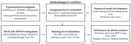
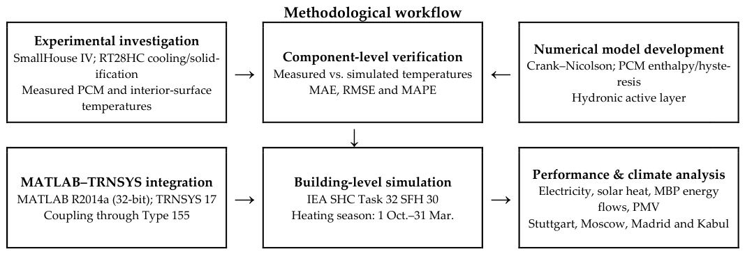
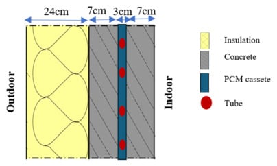
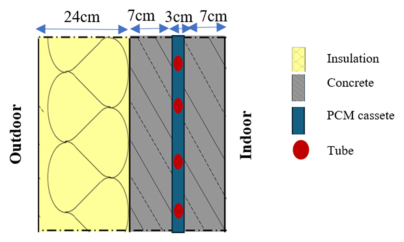
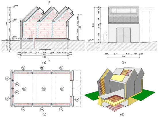

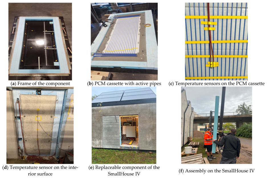
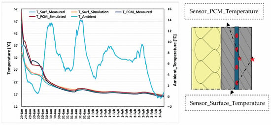
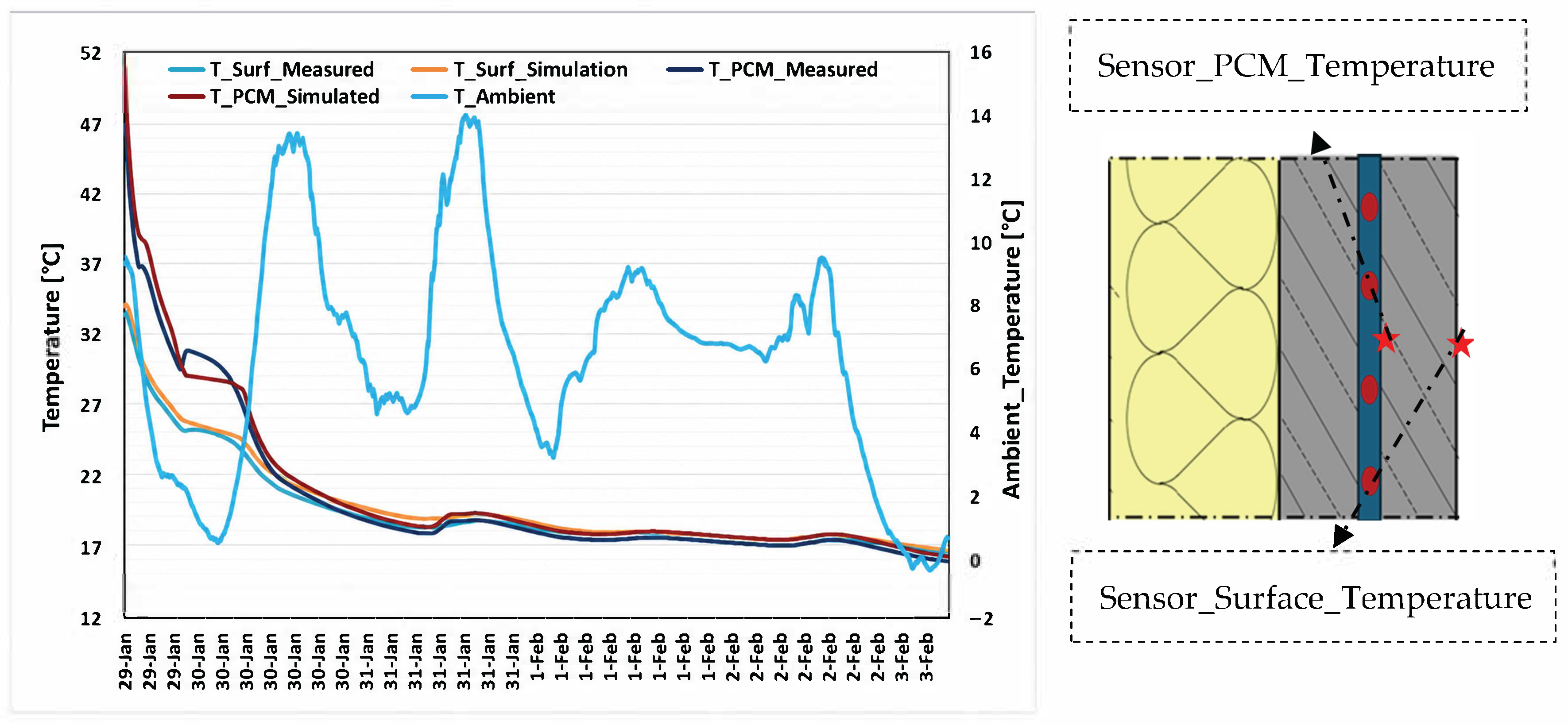
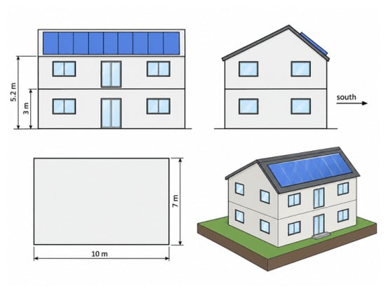
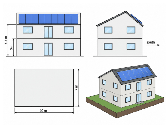
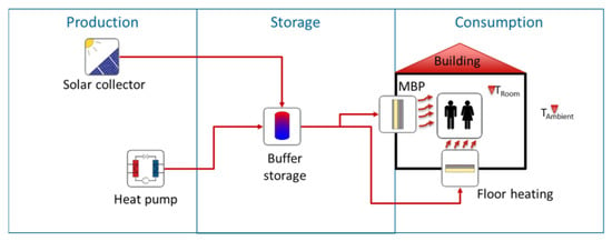
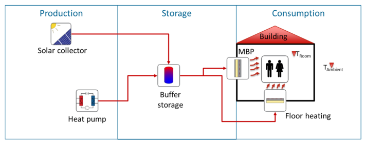
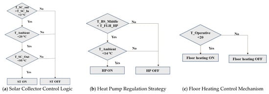
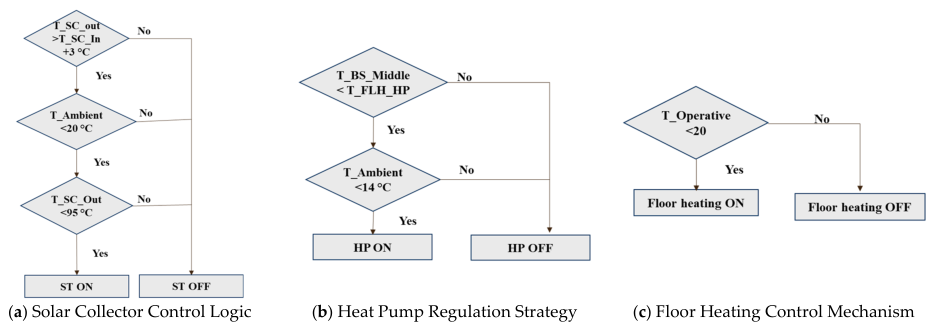
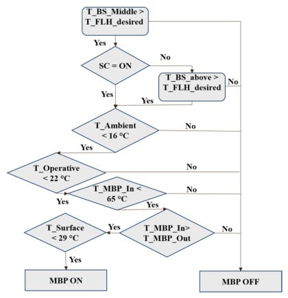
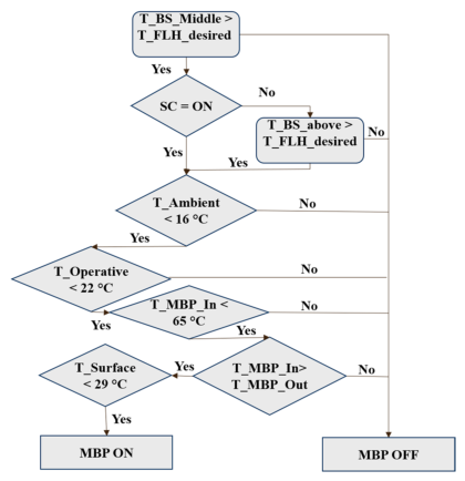
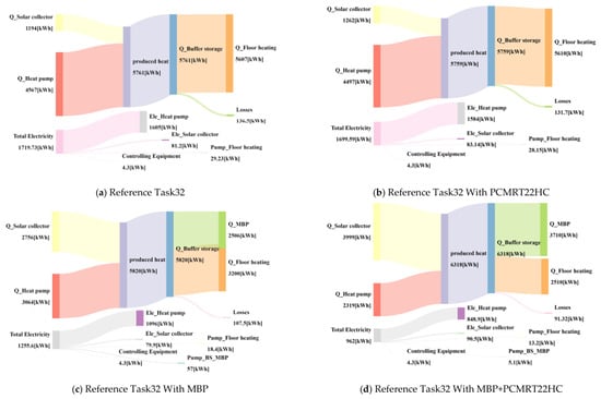
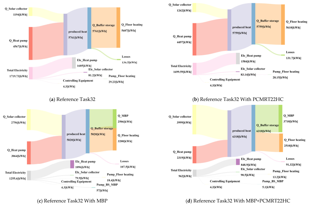
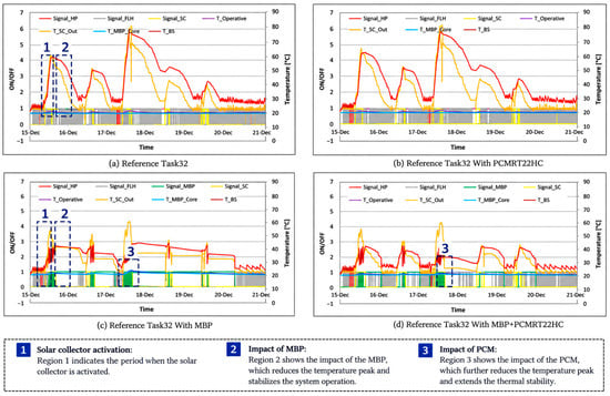
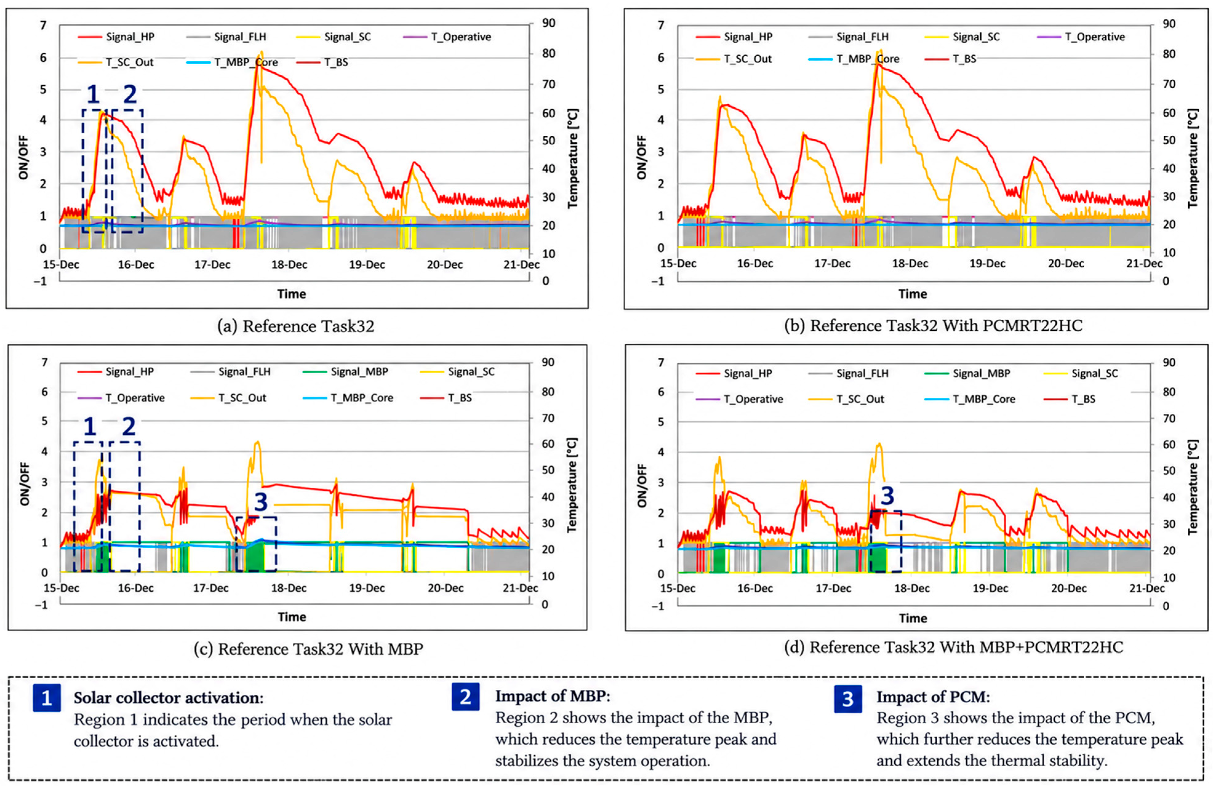
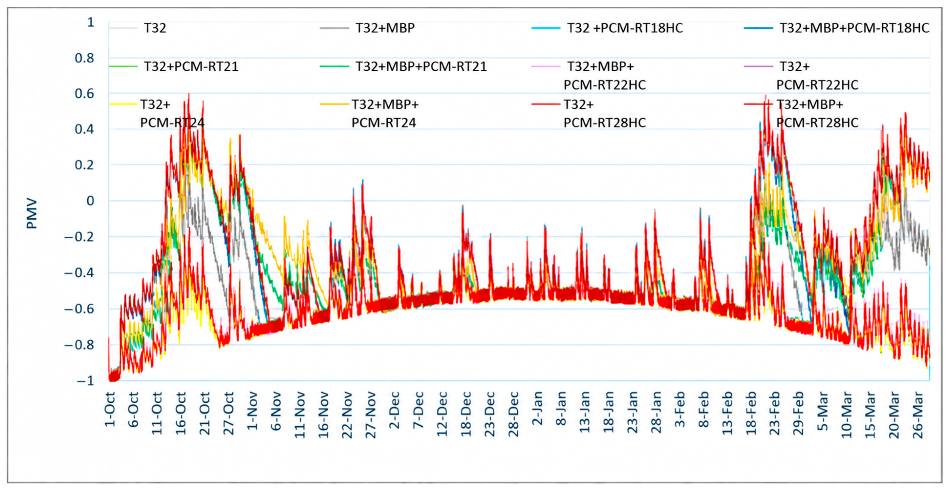
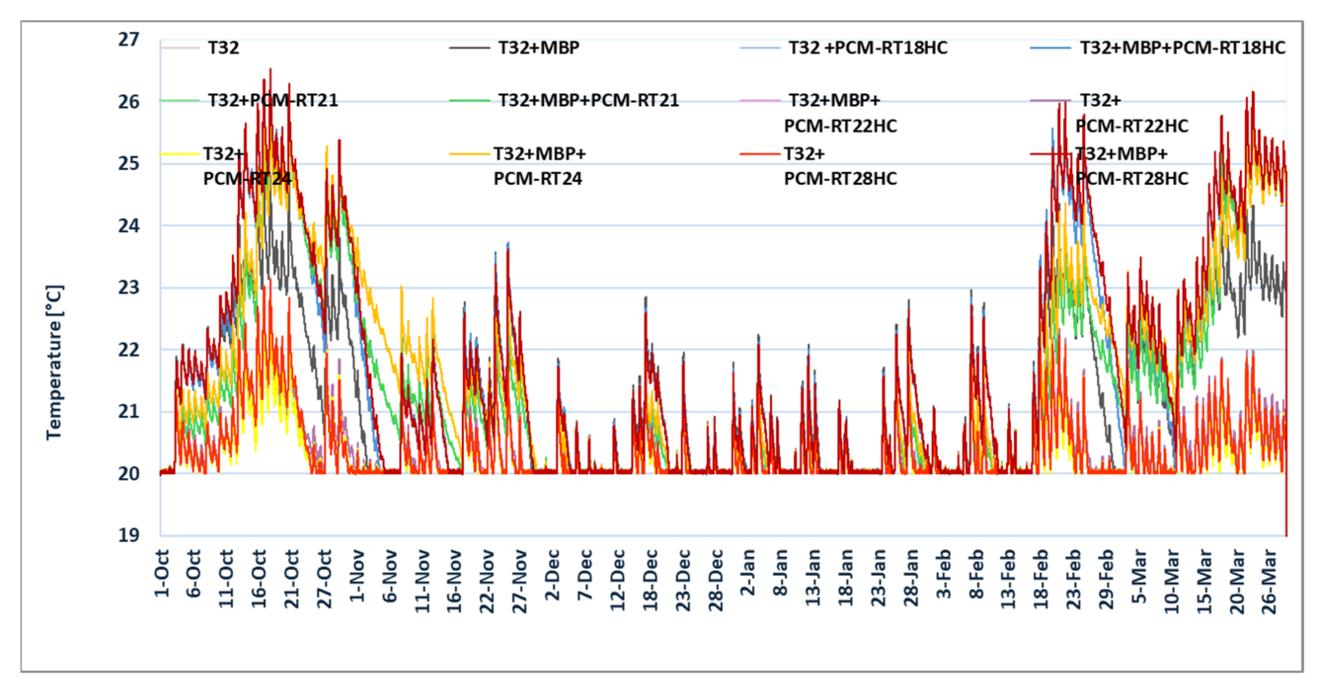

Disclaimer/Publisher’s Note: The statements, opinions and data contained in all publications are solely those of the individual author(s) and contributor(s) and not of MDPI and/or the editor(s). MDPI and/or the editor(s) disclaim responsibility for any injury to people or property resulting from any ideas, methods, instructions or products referred to in the content. |
© 2026 by the authors. Licensee MDPI, Basel, Switzerland. This article is an open access article distributed under the terms and conditions of the Creative Commons Attribution (CC BY) license.