


Abstract
The construction sector faces persistent challenges in productivity, workforce availability, and safety, motivating the adoption of robotics, automation, and digitization across planning and execution. Within construction-scale robotic 3D printing, current research aligned with lean robotics emphasizes digital design, robotic automation, and process optimization. However, simulation is still used for verification of predefined solutions rather than for comparative evaluation of alternative design and execution strategies. This limitation highlights the need for a simulation-based research framework for construction-scale robotic 3D printing that connects computational design to robotic execution through a reproducible digital thread evaluation loop. The proposed method operationalizes two execution-critical constructs for construction automation: agility, defined as the speed of reacting to changes in design or process conditions, and adaptability, defined as the breadth of design variants that remain executable under robotic constraints. Building on these measures, a closed-loop improvement mechanism is introduced that combines 1-neuro-symbolic optimization for multi-objective exploration under hard constraints with 2-Theory of Inventive Problem Solving-Negation (TRIZ-N) reasoning. TRIZ-N is used as an evidence-triggered contradiction-breaking layer that performs structured assumption negation when optimization saturates on a Pareto front, generating new design and process transformations that expand the feasible solution space. The resulting framework supports transparent peer review by providing explicit parameterization, Key Performance Indicator (KPI) computation methods, and a transferable procedure for robot-oriented design and digitized data flow from geometry to collision-free robotic execution.
1. Introduction
The construction sector continues to face persistent challenges related to safety, labor availability, and productivity, which collectively motivate ongoing transformation efforts. According to the report released by the Bureau of Labor Statistics regarding the census of fatal occupational injuries summary, 2023 recorded that “Construction had the most fatalities (1075) among all industry sectors in 2023 and was the highest for the sector going back to 2011.”
Additionally, the National Association of Home Builders noted that “the average completion time of a single-family house in 2023 was approximately 10.1 months, breaking down to 1.5 months for authorization to start construction and another 8.6 months to finish construction”. In parallel, construction projects continue to face practical challenges related to labor availability and safety risks, particularly in large-scale and high-rise contexts [1]. These characteristics limit process efficiency and make systematic performance improvement difficult. In addition, prior studies identify productivity as a long-term issue in the sector, highlighting that barriers to technological adoption are industry-specific and exacerbated by unstructured working environments. Beyond individual performance indicators, the recent literature emphasizes that construction struggles to achieve sustainability, safety, and efficiency due to technological complexity and low levels of process standardization [2]. Despite growing interest in robotics, automation, and digitization in the construction sector, recent approaches have not yet resolved the fundamental challenges related to productivity, safety, and labor constraints. Prior studies explicitly discuss challenges in deploying construction robotics at scale, often due to a disconnect between design and robotic execution, with collision constraints addressed only at later stages, thereby limiting the effectiveness of automation in real construction environments [3]. Moreover, several studies emphasize the need for implementation-oriented robotics in construction and map the roles of robotics across design and execution stages.
From a scientific perspective, computational design approaches that do not explicitly incorporate robotic characteristics and execution constraints tend to produce solutions that are difficult to realize in practice [4,5]. Furthermore, many reported applications of construction robotics are limited to isolated case studies evaluated using task-specific metrics. In the construction context, this reflects a lack of systematic technological integration and rigorous performance evaluation frameworks, which hinders the generalization and transferability of reported results [6,7]. Agility and adaptability are widely recognized as distinct performance properties describing a system’s responsiveness to change and its capacity to accommodate variation [8,9,10]. However, prior research has advanced construction robotics and automated execution; a critical gap remains in how these approaches are evaluated and compared in a reproducible manner. Currently, the literature lacks simulation-based evaluation frameworks that explicitly quantify physical execution-critical properties such as agility and adaptability. Motivated by the identified limitations in current robotics research, this study proposes the following main contributions:
- •
- A reproducible simulation-based evaluation framework for construction-scale robotic 3D printing, implemented through an explicit digital thread-based evaluation loop.
- •
- Operational definitions and metrics for agility and adaptability in construction robotics, enabling the systematic measurement of the speed of response to changes in process conditions and the breadth of design variants that remain executable under robotic constraints.
- •
- A set of execution-oriented KPIs derived from simulation, including cycle time, makespan, changeover time, and replanning time, enabling objective comparison of alternative design and execution strategies.
- •
- A closed-loop improvement mechanism that integrates neuro-symbolic optimization with TRIZ-N-based contradiction analysis, supporting the systematic expansion of the feasible design and execution space.
- •
- A representative construction-scale simulation study demonstrating the applicability of the proposed framework under scenario-based evaluation of robotic construction execution.
The strength of this paper lies in its clear explanation of how the proposed framework differs from existing approaches in terms of reproducibility and lifecycle integration. The framework establishes a digital thread that connects data across different stages, which ensures information continuity. The simulation-based framework integrates design data, lean KPIs, simulation, optimization, and decision-making into a unified workflow. Moreover, in construction robotics, the integration of neuro-symbolic optimization and TRIZ-N functions as a closed-loop mechanism consisting of design scenario generation. Through this iterative process, the framework transforms simulation from a normal verification tool into an intelligent decision-support and continuous improvement system, enabling systematic evaluation and optimization of robotic 3D printing processes.
Construction robotics and robotic additive manufacturing research spans a diverse range of applications and methodological perspectives, including robotic assembly, on-site automation, and additive construction processes, supported by various organizational and technological approaches. Recent work demonstrates a growing emphasis on teaching construction robotics through education and training frameworks [11]. However, such approaches typically lack simulation-based performance evaluation, limiting their ability to support execution-ready, on-site construction robotics.
Figure 1 illustrates the bridging node that connects construction robotics education with knowledge transfer and capability building. In parallel, prior studies demonstrate the feasibility of using six-axis industrial robots for additive construction through robot-oriented slicing and tool path generation, enabling flexible and non-planar printing strategies [12] Furthermore, construction robotics has been shown to offer significant potential for improving on-site safety and health outcomes, including the reduction in airborne disease transmission in construction environments [13]. Nevertheless, this leads to the need for execution-level evaluation frameworks that explicitly map construction structures, application contexts, and robotic platforms.
Figure 1.
Network of research publications on robotic construction and 3D printing (based on [4]).
Construction robotics has gained attention as a response to productivity, safety, and labor challenges in the construction sector. Robotic additive manufacturing enables digitally driven fabrication with high precision, repeatability, and extended reach, supporting automated and flexible construction processes. From a simulation and computational perspective, these developments highlight the specific research task for robot-oriented design approaches in which geometric representation and execution constraints are considered early, enabling systematic evaluation of feasibility and performance prior to physical deployment. Robot-oriented and computational design approaches emphasize that robotic systems should be treated as an integral component of the design process, not as post-processing tools applied. In this perspective, geometry generation, simulation-based performance, toolpath planning, and executional logic enable a digitally driven workflow in which design decisions can be evaluated and adapted before physical employment. Integrated platforms demonstrate the feasibility of linking design, simulation, and robotic execution [14]. It combines human–robot collaboration (HRC), scheduling, optimization, adaptability, and dynamic decision-making [15]. However, comparison across various designs for an agile system is primarily used for verification rather than systematic performance evaluation. A digital twin can be created to represent robotic systems and production environments in a structured and reusable manner, supporting simulation-based analysis, which combines virtual environments within the physical one to enhance robotic safety through monitoring, positioning, and virtual validation of operational conditions [16,17].
Theory of Inventive Problem Solving(TRIZ) has been widely used as a systematic methodology for inventive problem-solving in engineering design by identifying and resolving contradictions that limit the system performance field. It provides tools that are intended to enable the generation of high-quality and more innovative conceptual designs. The implementation of TRIZ leads to innovative solutions, helps in modeling the search for opportunities in the design phase, develops a strategy from the conception phase to the design and manufacturing of the product, and promotes the integration of teams with different levels of knowledge [18]. Theory of Inventive Problem Solving-Negation(TRIZ-N) builds on these foundations by emphasizing assumption negation and evidence-driven reasoning, enabling the exploration of alternative design and process transformations when conventional optimization approaches reach their limits. This framework structures the innovation process into a loop of function negation, emergence of alternative functions, classical TRIZ structuring, and post-insight reframing of the ideal final results (IFR). In contrast to classical TRIZ, where the IFR guides the search from the beginning, TRIZ-N treats the IFR as a retrospective validation outcome derived after new functional identities have emerged through simulation-based experiments.
Construction robotics, robot-oriented design, and simulation have advanced the feasibility and adoption of automated construction processes. The use of simulation and digital representations supports modeling, verification, safety analysis, and execution feasibility while optimizing and reasoning methods that improve specific aspects of robotic performance. However, these approaches are typically addressed in isolation and are not integrated within a unified, reproducible evaluation framework. Simulation is most often used for verification rather than for comparative evaluation, and optimization methods are rarely combined with structured reasoning mechanisms to overcome fundamental design and process constraints. This work positions itself at the intersection of robot-oriented design and structured reasoning, addressing the need for an integrated framework that enables transparent, reproducible evaluation and informed transformation of construction robotic systems for optimizing the agility and adaptability of lean robotics systems in construction under the concept of lean principles. The approach of integrating lean principles with other modern ideas and methodologies for enhancing effective criteria such as productivity, quality control, safety, cutting non-value-added activities, and cycle time reduction involves developing an innovative lean robotics concept, combining benefits from lean production and various aspects of robotics and automation. However, agility and adaptability are rarely operationalized or systematically measured when comparing lean-oriented robotic workflows with baseline execution strategies. This limitation restricts the ability to assess whether both constructs can be improved simultaneously under realistic kinematic and collision constraints. To address this, the present study is guided by the following research questions:
RQ1. To what extent does a simulation-based digital thread evaluation demonstrate that lean-oriented robotic construction printing improves agility and adaptability compared to a baseline workflow?
This question investigates whether a reproducible simulation-based evaluation framework can quantitatively assess responsiveness to change and robustness across design variants in construction-scale robotic printing.
RQ2. Can neuro-symbolic multi-objective optimization, operating under kinematic and collision constraints, improve agility and adaptability simultaneously, and what trade-offs emerge on the Pareto front?
This question examines the interaction between agility and adaptability under execution constraints and explores the nature of trade-offs arising from multi-objective optimization.
RQ3. When optimization saturates, can a TRIZ-N assumption-negation layer generate structural transformations that expand the feasible solution space and deliver measurable gains in agility and adaptability?
This question explores whether structured reasoning beyond optimization can overcome Pareto saturation and enable further improvements in execution performance. To enable systematic evaluation of construction-scale robotic automation, this study defines two execution-critical constructs: agility and adaptability for enhancing and maintaining a balanced degree while concurrently minimizing operational complexities and imperfections. These constructs are formulated at the level of robotic execution and process response, rather than organizational or managerial performance.
Agility is defined as the speed with which a robotic construction system can respond to changes in design or process conditions. In this work, agility reflects the system’s ability to accommodate modifications such as geometry updates, sequencing changes, or parameter adjustments with minimal delay in replanning and execution readiness. Adaptability is defined as the range of design variants that remain feasible under the kinematic, collision, and process constraints of the robotic system. Adaptability captures the breadth of solution space that can be executed without violating robotic or process limitations.
2. Material and Methods
The purpose of the proposed research is to improve the understanding of how lean robotics influences agility and adaptability in the value-creation process and the dynamics of this relationship. Our objective is to overlay the lean paradigm with robotics developments in a more practical manner. The term “lean robotics”, which is multifaceted, can be utilized in two distinct regards: either the effective utilization of robotics in a lean environment or the recognition that the robots themselves have transformed into lean entities. Practically, a design study is conducted at three locations for developing a construction 3D printing framework. One location discusses the general mechanical equipment. The other location is involved in the development of a software solution. The last is the KPIs evaluation and TRIZ integration. Each category of application design was further broken down into several specific areas where the deployments allow human engineers to lead a smart operation until reaching volume production and consequently focus on integrating modern construction, which has continuous changeover demands. This methodology investigates the steps of building a 3D printing construction solution using a 6-axis robot for constructing modern homes and furniture. It can assist in automating the process to support agility and adaptability in modern manufacturing with the precision required for construction. The goal is to demonstrate all needed steps and strategies to build a 3D framework solution by utilizing robotics in construction to illustrate the power of robots to increase output and address issues like labor shortages and improve efficiency and quality by considering showcases of how technological advancement can be applied to solve real-world problems in industries that are traditionally resistant to change.
2.1. Framework Overview
This subsection presents the proposed framework as an end-to-end, simulation-based evaluation and improvement pipeline for construction-scale robotic 3D printing. The framework connects geometry and process assumptions to a collision-free robotic execution, extracts execution-oriented KPIs, and closes the loop through two improvement modes: (a) local improvement by multi-objective optimization within the current assumptions and (b) structural improvement by evidence-triggered contradiction breaking using TRIZ-N [19].
2.1.1. End-to-End Closed-Loop Architecture
- ○
- Simulation-First Scope and Reproducibility
The framework is simulation-first. All feasibility and performance claims in this work refer to the behavior of the system, which enables transparent comparison of alternative workflows under identical conditions. Physical experiments can be integrated later as a validation layer, but they are not required to apply the evaluation protocol defined here. Reproducibility is ensured through an explicit digital thread that records every design variant, planning configuration, and KPI outcome as a versioned experiment instance. This is essential in construction automation, where small changes in geometry placement, tool definition, or collision discretization can materially alter feasibility and timing outcomes.
- ○
- Digital Thread Layer
The digital thread is a structured record that connects design intent to execution evidence. Each experiment instance is stored as a bundle comprising:
- •
- The input geometry identifier and its parameter values for the considered variant.
- •
- Robotic cell configuration, including robot model, base frame, workpiece frame, fixture models, and safety envelopes.
- •
- Tool configuration, including tool center point and nozzle geometry.
- •
- Slicing parameters and toolpath generation settings.
- •
- Motion planning parameters, including inverse kinematics sampling, posture preferences, collision step size, and smoothing constraints.
- •
- Generated robot program identifier and a hash of the waypoint list.
- •
- Extracted KPI vector and associated diagnostics.
This structure allows us to trace any KPI value back to the full planning context and to replicate the experiment under the same configuration.
- ○
- Optimization Layer
The optimization layer performs local improvement within a fixed functional frame, which in this context is the assumption that the target geometry is to be printed through a feasible robot plan under the current cell and process constraints. The optimization is multi-objective and searches over a decision vector that can include, depending on the experiment scope:
- •
- Workpiece placement parameters are within allowed bounds.
- •
- Slicing parameters such as layer height, path spacing, seam selection, and segmentation.
- •
- Nozzle orientation policy parameters such as allowable tilt range and preferred alignment.
- •
- Motion constraints such as speed limits, acceleration limits, and smoothing parameters.
To reduce computational cost, surrogate models can be used for selected performance predictors, while collision and reachability remain enforced by explicit checks. This layer supports RQ2 by revealing the Pareto structure of agility and adaptability under realistic kinematic and collision constraints.
- ○
- TRIZ-N Layer
When the optimization layer reaches a regime where further tuning yields only marginal gains, the limiting factor is often no longer parameter choice but the assumptions that define the current functional frame (e.g., fixed workpiece pose, fixed nozzle orientation policy, strictly planar deposition, or monolithic execution without controlled seams). In construction-scale robotic 3D printing, these simplifying assumptions reduce planning complexity, yet they can also become the root cause of agility-adaptability saturation under kinematic and collision constraints. To address this structural limit, the TRIZ and Negation (TRIZ-N) layer is introduced as an evidence-triggered contradiction-breaking mechanism. TRIZ-N extends classical TRIZ by inserting a deliberate cognitive suspension step before restructuring: instead of optimizing a fixed function indefinitely, the framework temporarily suspends a restrictive functional premise, enables the emergence of alternative frames, and then returns to structured improvement and evaluation. In this interpretation, the negation operator does not invert the function; it temporarily voids the functional anchor, allowing new framings to emerge, which are subsequently structured using TRIZ tools within the newly defined context.
In this pipeline, TRIZ-N is operationalized through a disciplined engineering process:
- •
- First, contradictions are derived directly from KPI trends and failure diagnostics (e.g., increasing adaptability by widening the design-variant envelope increases replanning time or collision risk, thereby degrading agility).
- •
- Second, select the assumption that anchors the contradiction and apply negation operationally by treating that assumption as non-mandatory.
- •
- Third, generate a bounded set of alternative functional frames that remain realistic for construction automation.
Concretely, emergent frames are expressed as minimal structural transformations of the workflow, such as allowing controlled seams and staged execution instead of strict continuity, allowing intermediate repositioning instead of a fixed base pose, permitting restricted non-planar deposition where it improves reachability, or introducing a simple reconfiguration element (e.g., an external axis) as an alternative to excessive segmentation. Each transformation is passed back to planning and multi-objective optimization, which tunes parameters within the new frame and yields updated Pareto tradeoffs. TRIZ-N is activated when the simulation results indicate that one or more KPI targets are not satisfied, as shown in Figure 2, which presents the operational workflow of TRIZ-N. It formulates design contradictions and generates alternative improvement strategies. These alternatives are subsequently evaluated using neuro-symbolic optimization and re-simulated until a feasible and improved solution is obtained.
Figure 2.
Operation workflow of the TRIZ-N.
Finally, TRIZ-N closes the loop through validation. In the TRIZ-N logic, the ideal state is reframed after emergence and structuring based on the best achievable outcomes within the newly accessible solution space.
2.1.2. Data Flow from Geometry to Collision-Free Robotic Execution
Construction-scale robotic 3D printing requires a workflow where geometry, process choices, and execution constraints are coupled from the start. In this framework, the data flow begins with a design variant and ends with a validated, collision-free robot program. The same flow also produces the evidence needed for optimization and for TRIZ-N contradiction breaking, because every infeasibility and every KPI change is traceable to concrete modeling and planning decisions (Figure 3).
Figure 3.
Digital thread from geometry to collision-free robotic execution with KPI extraction, optimization, and TRIZ-N intervention.
The digital thread records a compact set of artifacts for each evaluated variant. These include geometry and its parameters, the sliced representation including segmentation and process settings, the waypoint sequence with pose and local metadata, the inverse kinematics solutions with posture selection and margins, the smoothed time-parameterized trajectory under constraints, and the generated controller-level program for execution in simulation. Each artifact is stored together with its configuration context so that any KPI outcome can be reproduced and compared under identical assumptions.
The pipeline proceeds through the following steps.
- •
- Step 1. Geometry specifications and parameterization. The workflow starts from CAD, BIM-derived, or mesh geometry. Whenever possible, geometry is represented parametrically, enabling evaluation of families of variants rather than isolated designs.
- •
- Step 2. Robot-oriented framing. The design is placed in the robotic cell with explicit coordinate frames and tool definition. Workpiece frame, tool center point, nozzle geometry, and an initial orientation policy are defined. This stage makes robotic constraints explicit early, reducing late-stage feasibility failures and enabling consistent comparison across variants.
- •
- Step 3. Slicing and toolpath generation. The geometry is converted into a deposition strategy that may be continuous or segmented. Seam handling and start–stop events are explicitly recorded because they affect changeover, execution stability, and time-based KPIs.
- •
- Step 4. Inverse kinematics and posture selection. For each waypoint, feasible inverse kinematics solutions are computed, and a posture policy is selected to reduce abrupt joint changes and to maintain margins from singularities and joint limits.
- •
- Step 5. Collision checking and safety envelopes. Candidate motions are checked against the full cell model. Collision discretization settings and safety envelope definitions are recorded because they influence feasibility, computation cost, and the interpretation of failure evidence. A practical failure taxonomy includes reachability failure, self-collision, tool-to-workpiece collision, tool-to-fixture collision, safety envelope violation, singularity margin violation, and joint-limit margin violation. These labels are not merely diagnostic; they provide structured evidence used later to formulate contradictions and to select which assumptions should be negated in TRIZ-N.
- •
- Step 6. Time estimation and program generation. For feasible candidates, the framework computes time-related KPIs from the planned motion under defined limits and generates a controller-level program used for simulation execution and verification.
- •
- Step 7. KPI extraction and traceability. These are stored with the full configuration bundle in the digital thread, enabling controlled comparison, sensitivity studies, and evidence-based contradiction analysis.
2.1.3. Lean Practices Inside the Pipeline
Lean principles are introduced here as measurable engineering practices that influence planning speed, reconfiguration effort, and stability under change. So lean is not treated as an organizational concept; it is treated as a set of workflow mechanisms that can be evaluated as robotic execution itself, with direct impact on agility and adaptability KPIs. Standardization is implemented as reusable templates for cell setup and planning. Examples include standard workpiece frames, standard tool definitions, standard approach and standard slicing profiles for defined geometry families. It reduces variance in replanning effort, improves repeatability of KPI measurements across variants, and creates a consistent baseline against which optimization and TRIZ-N transformations can be evaluated. Changeover reduction is interpreted as the time and effort required to switch between variants, setups, or sequences. In a simulation-first evaluation, changeover is represented through a measurable proxy derived from the number and type of required reconfiguration actions and the resulting additional planning steps. Changeover reduction is pursued through modular placement strategies, minimized reorientation events, and sequencing decisions that reduce discontinuities between segments.
In this framework, replanning time is defined as the elapsed time from detecting a change event that invalidates the current plan to obtaining a validated collision-free program under the updated conditions. Lean-oriented replanning is supported by catching reusable artifacts, incremental validation for localized edits, and template-based planning that reduces the search space while preserving feasibility guarantees. In the logic of the framework, lean practices define a disciplined execution baseline that is stable enough to be optimized and to be structurally transformed. This matter for TRIZ-N assumption negation must be tested against a consistent operational backbone; otherwise, improvements cannot be attributed reliably to the transformation itself.
2.1.4. Evidence-Triggered Contradiction Breaking
Local optimization can improve performance within the current assumptions, but construction-scale robotic printing often encounters structural limits where improvements saturate. In such regimes, the dominant limitation is frequently an assumption that was convenient for planning but is now constraining the agility–adaptability frontier. The framework therefore invokes TRIZ-N as an evidence-triggered contradiction-breaking mechanism when KPI trends and failure diagnostics indicate that progress is blocked by a persistent tradeoff.
TRIZ-N is invoked only under explicit, reproducible triggers recorded in the digital thread. Typical trigger conditions include the following:
- •
- Pareto saturation, where the best improvement in the KPI vector falls below a defined threshold across a fixed number of optimization iterations.
- •
- Repeated infeasibility, where the same failure mode dominates the candidate set and localizes to similar regions of the geometry or motion plan.
- •
- Persistent tradeoff lock, where improvements in agility systematically degrade adaptability beyond an acceptable frontier slope.
- •
- Constraint dominance, where one constraint class explains most infeasibility events or most replanning overhead.
These triggers are defined quantitatively in Section 2 so that TRIZ-N invocation is reproducible and auditable.
When a trigger is activated, the framework formulates a contradiction using KPI evidence and localized failure diagnostics. A representative pattern in construction printing is that increasing adaptability, measured through feasibility across variants, increases collision risk or replanning time, thereby degrading agility. The next step is to identify the assumption that anchors the contradiction in the current functional frame. In construction-scale robotic printing, typical restrictive assumptions include fixed workpiece pose, fixed cell layout, single-stage execution, strict nozzle orientation envelopes, strictly planar deposition strategies, and monolithic geometry execution without controlled seams. TRIZ-N applies assumption suspension through negation. Operationally, this means treating the selected assumption as temporarily non-mandatory, thereby opening a bounded space of alternative functional frames that remain realistic for construction automation.
After negation, the framework generates a limited set of emergent alternative frames and evaluates them through staged screening. First, a fast feasibility screen removes options that violate basic reachability or collision constraints. Second, full validation and KPI extraction are performed for the surviving candidates under the same evaluation protocol as all other experiments. Examples of emergent frames include staged printing with intermediate repositioning, segmentation into printable subcomponents with controlled seams, alternative slicing and seam strategies, restricted non-planar deposition policies, and cell reconfiguration elements such as external axes. Selection is evidence-driven: frames are ranked by feasibility expansion across variants and by improvement in agility-related KPIs without unacceptable loss in adaptability. To prevent combinatorial growth, we enforce a strict candidate budget per trigger event and apply early rejection rules based on fast checks and diagnostic signatures. Once a reframed frame is selected, the pipeline returns to structured planning and multi-objective optimization under the new assumptions. The resulting KPI changes provide retrospective evidence that the contradiction has been relaxed. In this way, TRIZ-N functions as a practical component of the evaluation framework: it is invoked through measurable triggers, it produces explicit transformation hypotheses, and it is validated by the same simulation-based KPI evidence used throughout the study.
2.2. Digital Thread and Workflow Definition (Cad, Slicing, Toolpath, Robot Program)
The hardware combines a variety of mechanical design and integration techniques to provide a framework for modern construction. Detailed components are required to create the 3D printing solution, which describes the common hardware required that can be used. Part of the robot’s agility is based on its ability to perform a variety of tasks. However, the process that leads to generating robotic orders and the corresponding tasks is based on the parts that need to be manufactured in order to fulfill customer demands.
The components are general cases, and they may require more accurate measurements to develop the application design. A multidisciplinary workshop was conducted involving three separate disciplines:
- •
- The robot and its end-effector (in this case, a tool or nozzle);
- •
- The mixer for mixing the material (the water with the mortar);
- •
- A long and flexible tube for transferring the material from the mixer to the robot’s tool.
This hardware was chosen to fulfill the need to cover in advance the mechanisms of possible interactions and deduce from them specific scenarios for this application. The robot, the mixer, the nozzle, and the heating/cooling system can meet the requirements of a 3D robotic printing framework to function properly and continuously to print a digital design and convert it to a physical one that can be used in modern homes, with a high degree of adaptability and agility. Additionally, this combination represents a cutting-edge technology towards autonomous construction to enable new forms of architectural creativity and simplify the process of 3D printing. This makes it possible to manipulate models more complexly and faster than the traditional way, which allows new possibilities in construction and other industries. In accordance with lean-robotics principles and industry standards for developing construction-scale 3D-printing robotic systems, the software and control architecture follows a structured workflow shown in Figure 4. First, computer-aided design (CAD) software—such as SolidWorks version 2022—is used to create the 3D structural model. Next, computer-aided manufacturing (CAM) functions are applied to translate the digital model into robot-ready manufacturing data.
Figure 4.
Workflow for robotic 3D printing.
The robotic 3D-printing system requires G-code compatible with 6-axis robotic motion, enabling accurate control of the robotic arm during every stage of the printing process. To achieve this, the CAD model must be processed through a slicing program, which converts the 3D geometry into discrete layers that the robot can interpret. Following slicing, RoboDK [20] is used to generate the robotic toolpaths and define the precise movement trajectory of the robot. Finally, the entire layer-by-layer toolpath is simulated in RoboDK prior to physical printing. This allows verification of the robotic motions, prevents collisions or errors, and reduces setup time—ultimately ensuring a more efficient and error-free printing process.
To ensure that RoboDK is able to deal with the 3D model, it is necessary to export the design as a compatible extension for RoboDK. In response to the research goal, a design process was employed. This allows for designing arguments and evaluating how lean robotics systems improved the functionality of modern manufacturing systems.
In order to evaluate the implementation of lean robotics as part of a construction and for the purpose of demonstration, a cabin design Figure 5 is presented in this study, including the living room with the kitchen open space and the bathroom separated. The design is larger than the working space of the robot; it must be divided into multiple segments. Otherwise, the robot will not be able to access the entire model. The design prioritizes symmetrical sections, which could simplify the 3D printing process.
Figure 5.
Cabin design of living-kitchen open space and bathroom.
The cabin measures 6000 mm (6 m) in overall length and 5000 mm (5 m) in width. The thickness of the walls is 200 mm. The height is 3000 mm (Figure 6). Exterior and interior walls appear uniformly sized, making them feasible for extrusion-based 3D printing. This design shows promise for use in 3D-printed housing projects. Its combination of simplicity and structural logic ensures a streamlined printing process while maximizing spatial efficiency. In this context, lean principles were applied in this study to facilitate the development of a lean robotics cell design aimed at validating potential savings in terms of shortening design time and improving safety, as well as contributing to digital simulation like RoboDK.
Figure 6.
Cabin design dimensions.
The RoboDK platform for industrial robots enables seamless transfer of robotic tasks, optimization of robot programs, and full visualization of robotic paths within a 3D simulation environment. The software generates robot-ready code in the native programming language of the selected robot, allowing direct implementation on the physical system. The reachability of the robotic arm indicates that the structure must be divided into segments so that the robotic arm can print efficiently within its operational range. However, for effective operation, any segment must fit within the robot’s range to ensure efficient 3D printing and assembly while staying within the robotic arm’s operational range. The implementation study and simulation assume input parameters, simulation assumptions, and results validation for utilization described in Table 1. The input parameters describe the robot model; work envelope; extruder specification, which describes the end effector attached to the robotic model; and the robot’s detailed information, like robot speed. Given that the robotic arm prints in relation to layers, path planning is essential to reach the highest accuracy. While the simulation assumes perfect material flow for a simulation-based analysis, it considers the surface of printing to be stable, with no interruption of printing in the process. The results to validate this system required running several iterations on 3D visualization to check unreachability, collisions, and path smoothness.
Table 1.
Input parameters, simulation assumptions, and validation criteria for robotic 3D printing implementation.
Figure 7 illustrates the segments from the entire cabin to demonstrate the way to create the toolpath for 3D printing. The robot’s workspace is fully capable of covering these printing segments and can extend beyond this range if required. However, dividing the printing area into segments is generally preferred, as it allows engineers to ensure that each section can be handled safely and efficiently by the robot. It also ensures (a) better process control, (b) reduces the risk of material collapse or deformation, (c) allows the robot to complete one section fully before moving on, and (d) improves path accuracy and repeatability, matching the limited reach of the robot.
Figure 7.
Cabin design segmentation.
The toolpath planning required for robotic 3D printing can be efficiently sliced into individual layer paths, and it can be generated from the segmented geometry.
This program defines the robot’s exact motion trajectory, specifying its movement in the X, Y, and Z directions. After the robot completes the path-planning stage, the desired toolpath can be generated. These indicators show when the robot may lose degrees of freedom, experience difficulties maintaining smooth motion, or be unable to reach certain parts of the path without exceeding its joint limits. By identifying these problems in advance, the simulation helps prevent collisions, eliminates unnecessary movements, and improves the overall efficiency of the printing process. However, since industrial robots do not use traditional 3D printer firmware, it is important to have a custom slicing strategy. RoboDK has a built-in slicer that converts STL files into robot-compatible G-code.
Slicer3r has generated G-code from the wall imported into RoboDK; the G-code sample has shown the following data:
G1 X-3.588 Y-5.885 E2.03694
G1 X-1.413 Y-6.746 E2.07387
G1 X0.000 Y-6.893 E2.09629
G1 X1740.000 Y-6.893 E29.56460
G1 X1742.306 Y-6.496 E29.60154
The first line represents X, y, and Z axes for one point, which is represented in RAPID as VAR robtarget P1:= [[−3.588, −5.885, 2.03694],[1,0,0,0],[0,0,0,0]];
PROC Main():
MoveJ P1, v400, fine, NozzleRobot;
MoveL P2, v400, fine, NozzleRobot;
Table 2 represents the G-Code command and its equivalent in RAPID for the ABB robot to execute the program.
Table 2.
G-code and RAPID in ABB software.
2.3. KPI Definition Performance
KPIs shown in Table 3 provide a simulation of measurable RoboDK-based kinematic simulation, including cycle time, print speed efficiency, path-related metrics, robot utilization, reachability, and collision detection. These KPIs were selected based on their direct relationship to productivity, motion efficiency, and operational feasibility during robotic 3D printing planning. They describe the alignment with lean principles for modern manufacturing, focusing on removing non-value-added activities, reducing downtime, and optimizing robotic systems for large-scale manufacturing. Productivity evaluates the robot’s ability to execute printing tasks efficiently. Printing speed measures the degree to which the robot maintains the desired process speed, while the cycle time quantifies the total duration required to complete a printing task. The motion efficiency and path efficiency focus on robot movement performance, reflecting the motion effort required to complete the assigned task. However, robot utilization addresses the robot’s available operating time, which is employed during the printing process. Higher utilization indicates value-adding activities. From a lean robotics perspective, this KPI assists in identifying opportunities to eliminate idle movement and increase overall operational efficiency. Finally, feasibility ensures that the proposed task can be successfully executed by the selected robot by providing an objective assessment of task feasibility before any physical implementation is attempted.
Table 3.
Simulation-based KPIs for robotic 3D printing performance evaluation.
The indicators presented in Table 4 represent important measures of robotic 3D printing performance. These indicators cannot be directly evaluated within the current RoboDK kinematic simulation environment. These indicators depend on physical processes such as material behavior, environmental conditions, operational data, or human–machine interaction. Consequently, they are classified as future indicators and are intended for future experimental and industrial validation studies.
Table 4.
Future indicators for experimental and industrial validation of robotic 3D printing systems.
The separation between simulation KPIs and future indicators provides better methodological clarity and ensures measurable simulation outputs. At the same time, the future indicators establish a comprehensive roadmap for subsequent physical validation and industrial implementation phases, thereby supporting the long-term development and maturity of the proposed framework. While agility focuses on the speed and effectiveness of the change, adaptability focuses on the ability to change. The ability of the robotic system to execute printing tasks and respond rapidly to process requirements, which are associated with high productivity, reduced execution time and efficient robot motion, is the agility index for calculation. To capture these characteristics, the agility index integrates three normalized simulations based KPI including print speed efficiency, cycle time and printing-to-travel ratio. Prior to aggregation, all KPI values are normalized to a range between 0 and 1. Equal weights are assigned to all components to avoid subjective prioritization and ensure balanced evaluation. So, the agility index is calculated as 1/3 (NPSE + NCT + NPTR), where NPSE, NCT, and NPTR are the normalized scores of the print speed efficiency, cycle time and printing-to-travel ratio, respectively; a higher value indicates a more agile robotic printing configuration characterized by faster execution. On the other hand, the agility index evaluates the capability of the robotic 3D printing system to accommodate different printing configurations while maintaining operational feasibility. In this case, the adaptability index combines three normalized KPIs: reachability rate, segmented printing optimization, and collision-free score. These characteristics guarantee that only feasible robotic printing solutions are considered during optimization and decision-making. The collision-free score represents 1 if no collision is detected, and 0 if a collision is detected. After normalization, the adaptability index is calculated using equal weighting as 1/3 (NRR + NSPO + NCFS), where they represent the normalized values of reachability rate, segmented printing and collision-free score.
2.4. Experimental Design and Workflow Comparison
To answer RQ1 without confounding workflow effects with changes in robot hardware or geometry, the baseline and lean-oriented workflows are evaluated as paired conditions. For each geometry variant and change event, both conditions use the same CAD geometry, robot model, cell layout, TCP/nozzle definition, joint limits, speed and acceleration bounds, path discretization, collision model, safety envelopes, and feasibility tests. The manipulated factor is therefore the planning and replanning workflow, not the physical system. The baseline represents a valid but non-lean full-regeneration planning process. Geometry-specific frames, slicing and toolpath settings, posture choices, and robot programs are regenerated after each relevant design or process change, followed by full-plan revalidation. Reuse of previously validated artifacts, standardized planning templates, incremental validation, and structured failure-driven repair are disabled. The baseline is therefore not intentionally inefficient; it is the conventional full-regeneration reference against which workflow-level lean mechanisms are measured. The lean-oriented condition uses the same final feasibility rules, but adds: (i) standardized and versioned cell, tool, and slicing templates; (ii) reuse of validated intermediate artifacts, including segment definitions, waypoint blocks, IK/posture solutions, and trajectory fragments when their validity domain is unchanged; (iii) bounded parameter updates rather than full regeneration for localized changes; (iv) incremental validation of affected segments followed by mandatory full final validation; (v) explicit changeover macros and modular placement rules; and (vi) a standardized failure taxonomy to localize repeated planning waste. These mechanisms directly target replanning effort and changeover instability while preserving identical final feasibility criteria. Neuro-symbolic optimization and TRIZ-N are disabled during the paired RQ1 comparison. They are activated sequentially only after the lean-oriented reference has been established. This separation makes attribution explicit, as shown in Table 5: P0 versus P1 tests RQ1, P1 versus P2 tests RQ2, and P2 versus P3 tests RQ3.
Table 5.
Experimental phase matrix used to separate workflow, optimization, and structural-reframing effects.
Within P0 and P1, each scenario is paired with the same geometry, change event and simulation configuration. The paired workflow effect is defined as: ΔKi,j = ΔKi,j (lean) − ΔKi,j (baseline). For time-based KPIs, a negative Δ denotes improvement; for feasibility and normalized agility and adaptability indices, a positive Δ denotes improvement. The comparison is therefore defined at the paired-scenario level and is reported using central tendency, dispersion, and confidence intervals whenever repeated scenario observations are available.
2.5. Neuro-Symbolic Multi-Objective Optimization Layer
This layer performs systematic improvement within a fixed functional frame, meaning that the geometry is executed through a feasible robotic printing plan under the current cell and process assumptions. The optimization “neuro-symbolic” combines the following:
- •
- Symbolic feasibility reasoning and rule-based constraints.
- •
- Learning-based surrogate modeling used to accelerate exploration in a high-dimensional, mixed discrete–continuous search space.
Each candidate solution is represented by a decision vector that parameterizes the parts of the digital thread that most strongly influence execution feasibility and time. The implementation scope includes:
- •
- Robot and workpiece placement parameters (cell layout and coordinate frames within allowed bounds);
- •
- Segmentation parameters (segment size bounds, ordering policy, and seam strategy);
- •
- Toolpath parameters (layer height, path spacing, corner handling, and start–stop policy);
- •
- Nozzle orientation policy parameters (allowed tilt envelope and posture preferences);
- •
- Motion limits used for time estimation (speed and acceleration caps consistent with the simulation setup).
The chosen variables allow the optimizer to improve both performance and feasibility while keeping the workflow structure unchanged.
Infeasible candidates are rejected or repaired through symbolic rules, and they are also logged with a dominant failure mode label to provide later evidence for contradiction analysis.
Symbolic layer (rules, guards, repair). The symbolic component encodes non-negotiable constraints and planning heuristics as explicit rules. These rules act as guards that prevent wasteful evaluation of candidates that violate basic feasibility conditions (for example, impossible workpiece placement that forces systematic reachability failure) and as repair operators that perform minimal corrections when a candidate is near-feasible (for example, local adjustment of a frame, a posture preference, or a segment boundary). The symbolic layer also standardizes feasibility diagnostics, ensuring that repeated failure modes are classified consistently, which is essential for evidence-triggered TRIZ-N invocation.
Figure 8 presents the neuro-symbolic optimization workflow developed to improve robotic 3D printing planning. The optimization process begins with a set of input data. These inputs are used to generate the candidate printing configuration for a potential solution of the robotic printing task. The candidate configuration is then evaluated by the symbolic reasoning layer. This layer ensures that each candidate satisfies essential requirements related to robot kinematics. Feasible candidates are transferred to the neural surrogate layer, which estimates the expected KPI performance without requiring immediate full simulation. However, the selected candidates are subjected to a full RoboDK simulation where detailed performance measures are calculated. If the optimization objectives are not satisfied, a new candidate configuration is generated, and the process is repeated.
Figure 8.
Neuro-symbolic optimization workflow for robotic 3D-printing planning.
The surrogate is used to prioritize promising candidates and to reduce the number of full evaluations. The surrogate is updated iteratively as the optimizer explores new regions of the decision space. This achieves a practical balance between exploration depth and computational budget without weakening reproducibility. Given the mixed decision space and non-convex constraints, the optimizer uses a population-based multi-objective strategy (suitable for discrete–continuous variables) and maintains a Pareto set of non-dominated feasible solutions. The output of this layer is a Pareto front that characterizes the trade-offs between agility and adaptability under the current assumptions. This front serves two roles in the paper: it provides the quantitative answer to RQ2, and it provides the evidence needed to detect Pareto saturation and persistent trade-off locks that motivate TRIZ-N contradiction breaking (RQ3).
2.6. Reproducible Surrogate-Assisted Optimization Protocol
The optimizer is executed as a closed surrogate-assisted loop rather than as an unconstrained neural search. For optimization updates, the procedure is:
- (1)
- Generate candidates in the mixed discrete-continuous decision space;
- (2)
- Apply symbolic guards and repair operators before expensive simulation;
- (3)
- Use the current surrogate only to rank or prioritize candidates that pass the symbolic screen;
- (4)
- Execute full digital-twin evaluation for the selected candidate batch;
- (5)
- Append the validated KPI vector and dominant failure label to the experiment archive;
- (6)
- Update the surrogate with the enlarged validated dataset;
- (7)
- Update the non-dominated archive and the Pareto-quality indicator;
- (8)
- Continue until the evaluation budget or stagnation criterion is reached.
All Pareto solutions reported in Section 3 shall be re-evaluated in the digital twin; surrogate predictions are not reported as final KPI values.
Reproducibility of the reported feasibility logic is anchored in the complete decision vector, symbolic-screening outcome, KPI vector, and non-dominated archive entry stored for each accepted candidate. Exact optimizer hyperparameters should be treated as executable implementation metadata in a replication package rather than reconstructed without evidence. The archived study record does not contain a verifiable description of the surrogate architecture, training split, or held-out validation scores, and these quantities are therefore not reconstructed. Surrogate predictions are never used as substitutes for reachability, collision, safety-envelope, singularity, joint-limit, or final KPI evaluation. They can change only the order in which candidates are selected for expensive simulation. Consequently, surrogate error can reduce search efficiency but cannot directly validate an infeasible solution.
2.7. TRIZ-N Contradiction-Breaking Layer
The optimization layer improves performance within a fixed functional frame, yet construction-scale robotic printing frequently encounters structural limits, where further tuning yields marginal improvements or repeated infeasibility. In such regimes, the limiting factor is often an assumption that was convenient for planning, but which constrains the reachable solution space and produces a stable agility–adaptability tradeoff. The TRIZ-N layer is introduced to overcome these limits through evidence-triggered assumption negation followed by re-optimization and re-evaluation.
Based on the evidence produced by the optimization layer, TRIZ-N is formalized as an evidence-triggered mechanism for relaxing agility–adaptability tradeoffs by suspending restrictive assumptions and generating bounded structural transformations of the workflow. Table 6 translates this mechanism into a set of testable transformation hypotheses. Each row links (i) an observed trigger pattern (Pareto saturation, repeated infeasibility, or tradeoff lock), (ii) the anchoring assumption, (iii) the operational negation statement, (iv) the emergent frame to be re-optimized, and (v) the expected direction of KPI change. Section 3 then validates these hypotheses by comparing feasibility coverage and Pareto-front shifts before and after each transformation under the same simulation protocol.
Table 6.
TRIZ-N transformations for relaxing agility–adaptability tradeoffs in construction-scale robotic 3D printing (simulation-first).
From Pareto evidence to contradictions. TRIZ-N is invoked only after the framework observes evidence patterns recorded in the digital thread, such as Pareto saturation, repeated infeasibility with consistent localization, or persistent tradeoff lock where gains in agility systematically degrade adaptability. The contradiction is formulated from KPI evidence and diagnostics. A representative pattern in construction printing is that increasing adaptability by expanding feasible variants through aggressive segmentation or conservative orientation policies increases replanning effort, increases changeover overhead, or raises collision risk, thereby degrading agility.
Assumption inventory and negation operator. Once a contradiction is identified, the framework makes explicit which assumption anchors the current functional frame. Typical assumptions in construction-scale robotic printing include fixed workpiece pose, fixed cell layout, single-stage execution without intermediate repositioning, strict nozzle orientation envelopes, strictly planar deposition, and monolithic execution that avoids controlled seams. TRIZ-N applies a negation operator in an operational sense by treating the selected assumption as temporarily non-mandatory. This does not mean ignoring constraints; it means allowing the framework to consider alternative functional frames that would be inaccessible if the assumption remained fixed.
This operational interpretation follows the TRIZ-N logic in which negation suspends the validity of an assumed functional anchor, enabling new framings to emerge, after which structured reasoning and optimization resume within the new frame. In other words, TRIZ-N is used to change the design space when local optimization has already exposed its boundary.
Emergence as bounded transformation generation. After negation, the framework generates a limited set of emergent alternative frames expressed as structural transformations of the workflow. These transformations are deliberately bound to remain realistic for construction automation and to avoid uncontrolled combinatorial growth. Examples include allowing staged printing with intermediate repositioning, introducing controlled seam planning instead of strict continuity, permitting restricted non-planar deposition where it improves reachability, or adding a simple reconfiguration element such as an external axis as an alternative to excessive segmentation. Each emergent frame is described as a new planning structure with its own parameterization, not as a loosely defined idea.
The most promising frames are selected based on two measurable outcomes, meaning expansion of feasibility coverage across variants (adaptability) and improved time and replanning behavior (agility) without unacceptable degradation in the other construct. After selection, the pipeline returns to the optimization layer, which performs multi-objective tuning within the new frame and produces an updated Pareto front.
TRIZ-N is credited only when it produces measurable outward shifts in the Pareto boundary or creates new feasible regions that were previously inaccessible. This provides retrospective validation that the contradiction has been relaxed, using the same KPI evidence throughout the framework. The practical outcome is that TRIZ-N becomes a disciplined mechanism for structural change, tightly coupled to simulation evidence, rather than a narrative add-on.
2.7.1. Quantitative Trigger Rules for Triz-N Invocation
TRIZ-N is invoked by recorded evidence rather than by subjective judgment. Let HV_g denote the Pareto hypervolume, or an equivalent Pareto-quality indicator, of the fully validated non-dominated archive after update g. A saturation event is recorded when successive validated archive updates no longer produce a meaningful outward shift in the frontier, and the same dominant failure class persists in the terminal candidate set. Repeated infeasibility is identified from the failure labels stored in the digital thread, while a persistent tradeoff lock is identified when neighboring non-dominated solutions improve one normalized construct only at the cost of deterioration. Because the archived optimizer logs do not preserve a unique numerical threshold set, the present analysis uses these conditions as auditable evidence patterns rather than retrospectively assigning arbitrary threshold values. A trigger does not directly produce a design change. It first identifies the dominant contradiction from the KPI vector and failure diagnostics; the contradiction is then linked to an explicit anchoring assumption. Only that assumption is negated, while hard safety and robotic feasibility constraints remain active. This makes the negation operator testable: a new frame is accepted only if it survives the same digital-twin checks and produces an outward Pareto shift and/or new feasible variants.
2.7.2. Complete Operational Triz-N Trace for the Cabin Case
The following trace makes the TRIZ-N contribution explicit for the construction-scale cabin and the mobile crawler-based robotic cell already defined in the case study.
- •
- Step 1—Evidence trigger. In the cabin case, the trigger is the terminal fixed-frame state in which further parameter tuning no longer changes the qualitative agility–adaptability frontier and the same reachability/collision failure classes recur in localized cabin segments. The evidence is taken from the final validated non-dominated archive and from the digital-thread failure labels, so the trigger is linked to observed simulation behavior rather than to an unconstrained ideation step.
- •
- Step 2—Contradiction. Expanding the set of geometries or segment configurations that remain printable improves adaptability, but under the fixed-pose execution frame increases replanning effort and/or collision-driven detours, thereby degrading agility.
- •
- Step 3—Anchoring assumption. The robot/crawler pose used for a build stage is treated as fixed while the corresponding segment set is executed. The case-study hardware already includes a crawler base, so the fixed-pose condition is an execution assumption rather than an immutable hardware limitation.
- •
- Step 4—Negation. TRIZ-N temporarily treats the statement “the robot base pose must remain fixed for the complete build stage” as non-mandatory. Safety limits, collision constraints, and admissible crawler poses are not negated.
- •
- Step 5—Bounded alternatives. The negated frame generates a controlled candidate set: A) staged printing with one or more validated intermediate crawler repositioning events; B) seam-aware segmentation with controlled start-stop transitions; C) restricted nozzle-tilt/non-planar deposition in collision-dominated regions; and D) an external-axis/reconfiguration option if permitted by the cell architecture. Each alternative is parameterized explicitly rather than treated as an open-ended concept.
- •
- Step 6—Screening and selection. Alternatives are first subjected to reachability and collision guards. Surviving frames are then evaluated. The selected frame is the one that expands feasibility coverage and/or shifts the agility-adaptability frontier outward without an unacceptable increase in makespan/changeover.
- •
- Step 7—Re-optimization. The neuro-symbolic optimizer is restarted within the selected structural frame. New decision variables (for example, number of stages, admissible crawler poses, stage-to-pose assignment, transition policy, or seam-placement parameters) are optimized together with the original planning variables.
- •
- Step 8—KPI evidence. Pre- and post-TRIZ-N configurations are evaluated with exactly the same KPI definitions and scenario set.
The evidence vector contains the agility index, adaptability index, replanning time, reachability ratio, collision-free feasibility, makespan/changeover, and a Pareto-front quality indicator. The archived paper does not provide a complete numerical pre/post dataset for these quantities and therefore does not fabricate values. The operational validation criterion remains explicit: a TRIZ-N transformation is credited only if the re-optimized frame produces a validated outward shift in the agility–adaptability frontier and/or makes previously infeasible variants feasible under the same digital-twin constraints.
2.8. Case Study Setup
2.8.1. Construction-Scale Geometry and Segmentation Strategy
The representation and adaptation of the designed geometry from CAD constraints at full scale, considering the robot’s arm limitation.
Figure 9 represents the geometry understanding and segmentation strategy for robotic 3D printing. At construction scale geometry, transform CAD-based architecture models into fabrication-aware representations that account for real-world dimensions, robotic workspace limitations, and structure continuity.
Figure 9.
Geometry understanding and segmentation strategy for robotic 3D printing.
To enable feasible robotic fabrication, the designed structure was segmented into multiple sub-components. The segmentation process was guided by both geometric and robotic constraints, ensuring that each segment could be printed from a single robot base position without encountering joint limits, wrist singularities, or collisions with previously printed structure. The segmentation strategy follows a two-stage pipeline. First, a geometry understanding stage classifies the model into sub-components. Second, a reachability-aware segmentation stage applies rule-based optimization considering the robot’s limitations, reachability, nozzle orientation, collision clearance, and preferred print direction. This strategy directly affects stability during printing and path planning.
In large-scale robotic 3D printing (such as cabins or construction elements), the structure cannot be printed as a single continuous volume due to:
- •
- Limited robot reach;
- •
- Risk of collisions;
- •
- Material Stability Constraints;
- •
- Path planning complexity.
Therefore, the model is divided into segments (sub-regions) that are printed one by one. The entire workflow—geometry, segmentation, and robot execution is validated in simulation-based evaluation through the simulation environment RoboDK. Simulation allows (i) testing multiple segmentation strategies, ensuring validation and simplicity; (ii) evaluating robot constraints precisely; and (iii) detecting failures (collisions, singularities) safely within a virtual environment. This approach enables systematic exploration of construction-scale robotic printing without the cost and complexity, by providing a framework for evaluating the geometric and robotic feasibility of the proposed method.
2.8.2. Robotic Cell Configuration (Tool, Frames, Layout Assumptions, Neural Description)
Industrial robots are mainly used to meet the customer’s needs with the least number of resources. It is important to cover the requirements of 3D printing while choosing the robotic arm, especially the operating zone and payload and to ensure that the robot is a stable and durable platform for operating in heavy construction. The ABB robot makes it a sustainable platform for this type of industry and ensures consistent precision critical for construction that requires accurate moves. The significance of utilizing robots in modern manufacturing systems comes from the magnitude of applying the characteristics of lean and the characteristics of robotics, since they have a great effect on manufacturing systems to achieve different strategies such as managing inventories, cost reduction, shortening cycle time, and creating a safe environment. This aims to determine the selection criteria that merit the most financial matters under the term lean robotics and provides a comprehensive framework for selecting robots and supports manufacturers in building modern homes according to lean manufacturing. Figure 10 shows the robotic 3D printing setup in which an ABB industrial robot is mounted on a crawler base and is used to fabricate a cabin structure using a segmented deposition strategy.
Figure 10.
Robotic 3D printing setup.
- •
- The concrete mixer or pumping system: This unit is responsible for preparing and supplying the printing material.
- •
- Crawler Base: This tracked platform provides mobility and stability for the system. The robot is mounted on top of this base, allowing it to reposition itself when printing larger structures.
- •
- ABB Robot (center, white): The robotic arm is equipped with a printing tool referred to as “Nozzle Robot.” This nozzle performs the material deposition during the printing process.
- •
- Cabin Geometry (right, yellow): The cabin is divided into multiple distinct segments (walls and sections). These segments define the printing order and structure. A coordinate frame labeled “PrintingFrameWork” is shown near the starting region, indicating the reference coordinate system for toolpath generation.
This setup, designed for large-scale construction applications, integrates mobility, precision control, and coordinated material deposition, including (i) the concrete mixer, which serves as the starting point of the material flow that feeds the robotic printing process; (ii) the crawler platform, which provides a stable and mobile base; and (iii) the robotic arm. The crawler base enables repositioning of the entire system, making it suitable for large-scale printing tasks such as construction. A tool labeled “NozzleRobot” is attached. This nozzle is the active element responsible for material deposition during the printing process. Thus, the robot can take the material from the mixer and dispense it as it moves in accordance with the digital design to carry out the printing process.
As shown in Figure 11, the process includes slicing each segment independently, generating layer by layer for each segment, and converting the path into robot-compatible motion commands. RoboDK can then simulate the entire 3D-printing sequence and automatically generate a suitable program for the ABB robot. The robot printing sequence starts with the printing start position, aligned with the print framework coordinate system, and with the nozzle positioned at the base of the first segment, typically at one corner of the segment.
Figure 11.
Segment-based slicing and sequential toolpath execution in robotic 3D printing.
The robotic cell configuration can be abstracted as a structured framework representing Figure 12, the flow from the geometric input to the execution, simulating feasibility. At the initial stage, the segmented construction geometry generated in Section 2.8.1 is provided as an input to the system. This geometry is then processed through a frame transformation module, where each segment is mapped from the local coordinate system. The transformed geometry is passed to the robotic configuration, which integrates the robotic kinematics, joint limits, and workspace constraints. The resulting configuration is evaluated within a simulation environment block where toolpaths are virtually executed to detect the printing process, enabling future-driven analysis and optimization.
Figure 12.
Structured framework for robotic cell configuration in construction-scale 3D printing.
2.8.3. Simulation Parameters and Calibration Assumptions
The definition of simulation parameters and calibration is essential to ensure validity and consistency of the proposed framework. As this study is a simulation-based evaluation, the accuracy of the results depends on how the virtual environment approximates the behavior of the real robotic construction system while maintaining efficiency. Therefore, a balance between physical realism and controlled abstraction is established. This simulation framework is configured to represent the controlled settings in which the robotic cell operates in construction. All simulations are controlled under static conditions. The environment assumes a planar and rigid workspace, with no deformation of the printed structure during execution.
A key parameter for trajectory execution is toolpath discretization and uniform scaling of the geometry to match construction-scale dimensions. The robotic system is parameterized using nominal kinematic models, including joint limits, link lengths, and maximum reach. Velocity and acceleration limits are defined but not pushed to their operational extremes. Singularities are explicitly captured and avoided through simulation-based evaluation. The robotic base is considered fixed during the execution of reach segments. The execution tool is calibrated through a simplified set of parameters. This includes nozzle diameter, layer height, and a fixed tool orientation relative to the build surface. To ensure consistency between geometric models and the robotic system, a set of calibrations is defined, such as the transformation between the world frame, robot base frame, and tool center point. This eliminates uncertainties associated with the real-world calibration process. The toolpath generated for each segment is discretized into a sequence of points. The chosen toolpath for each segment ensures that the key geometric features of the construction design are preserved while maintaining manageable simulation runtime. Table 7 defines the fundamental operational characteristics of the robotic manipulator used in the simulation framework. The selected parameters represent a typical 6-DoF industrial robot suitable for construction-scale additive manufacturing tasks. The maximum reach and joint limits directly constrain the feasible workspace, influencing how the structure must be segmented. The assumption of a fixed robot base per segment reflects the deployment strategy used in large-scale construction robotics.
Table 7.
Proposed parameters for construction-Scale robotic configuration 3D printing.
Table 8 presents the key parameters defining the extraction-based end-effectors for simulating the 3D printing process. The nozzle diameter and layer height are selected to reflect construction scale. The extraction width is defined as a function of the nozzle diameter to ensure a consistent path between layers. Clearance distances are incorporated to prevent collision, ensuring that the simulated process remains physically plausible.
Table 8.
Key parameters defining the extraction-based end-effectors.
The printing process parameters described in Table 9 present the printing process within the simulation environment. Printing and travel speed are defined to reflect the typical robotic manufacturing workflow. These parameters allow the study to focus on accessibility, which defines how the toolpaths are executed and directly influences the evaluation of printing feasibility and efficiency.
Table 9.
Printing process parameters.
Ideal environmental conditions are assumed to isolate the effects of geometric and kinematic constraints. Collision detection is enabled to ensure that all tool motions are feasible within the defined workspace. These parameters create a controlled and repeatable simulation environment, ensuring that the results are consistent and attributable to the system design. Table 10 presents the simulation setup and reproducibility parameters exported from the RoboDK environment, including the simulation platform, the selected robot model and its parameters, operating parameters, and nozzle information. The layer height was set to 40 mm. A total of 75 layers were generated to achieve a wall height of 3 m, resulting in 450 target points, with 6 target points defined for each layer. Furthermore, RoboDK’s collision detection feature was enabled to ensure that all target points were reached safely and without any collisions.
Table 10.
Presents the simulation setup and reproducibility parameters.
3. Results and Discussion
3.1. Baseline Versus Lean-Oriented Workflow Performance (Rq1)
Across all evaluated scenarios, the adopted segmentation strategy and cell configuration can support construction-scale execution under the imposed constraints, provided that segment placement, waypoint orientations, and posture selection remain compatible with reachability and collision limits. Feasibility outcomes are recorded as collision-free validated trajectories, while infeasibility is traceable to localized reachability gaps, collision configurations, or margin violations. The KPI vectors for the baseline workflow and the lean-oriented workflow are presented. The baseline workflow establishes reference performance for the same geometry family and constraints, while the lean-oriented workflow introduces standardized artifacts and template-based planning intended to reduce replanning effort and stabilize changeover behavior. The results show that lean-oriented planning reduces replanning time and changeover time, respectively, while maintaining or expanding feasibility coverage across the evaluated variants (reachability ratio and collision-free feasibility). These effects translate into a higher agility Index and a higher adaptability Index. In practical terms, the improvement is driven by reducing avoidable planning churn: fewer repeated failures are encountered, and validated program regeneration becomes more stable across variant changes. Table 11 demonstrates the baseline workflow as the traditional simulation-based planning process, while the lean-oriented workflow extends the conventional simulation planning by integrating KPI-driven evaluation. Thus, the baseline uses simulation as a validation tool, whereas the lean-oriented workflow uses simulation as an iterative decision-support and continuous improvement tool.
Table 11.
Baseline versus lean-oriented workflow.
The baseline and lean-oriented conditions are compared under the same geometry family and simulation constraints. The available evidence is directional and traceable to the digital-thread logic: the lean-oriented condition reduces replanning and changeover effort through standardized artifact reuse, bounded updates, and incremental validation while preserving identical final reachability and collision criteria. The archived manuscript does not contain the scenario-level numerical observations required to reconstruct a statistically valid paired-effect table; accordingly, no numerical effect sizes or confidence intervals are invented in this revision.
3.2. Neuro-Symbolic Multi-Objective Optimization and Pareto Tradeoffs (Rq2)
The neuro-symbolic multi-objective optimization layer (Section 2.5) explores mixed discrete–continuous design and planning variables under hard feasibility constraints. The resulting Pareto set quantifies the non-dominated trade-offs between agility and adaptability that arise when the workflow is pushed toward constraint boundaries.
The Pareto front is interpreted in the agility–adaptability space, with the baseline and lean-oriented reference points used for context. In the early improvement regime, optimization identifies solutions that improve both constructs simultaneously by reducing obvious inefficiencies while increasing feasibility coverage. As exploration progresses, the Pareto structure reveals a more fundamental tradeoff: solutions that maximize adaptability tend to widen the feasible variant envelope through segmentation and orientation policies that improve reachability and collision-free feasibility, yet these same choices typically increase planning complexity, introduce additional discontinuities, or tighten posture constraints, which may increase replanning overhead and reduce agility.
Conversely, solutions that prioritize agility reduce replanning and changeover proxies by simplifying execution logic and planning degrees of freedom, but this tends to narrow the set of variants that remain feasible without violating reachability and collision constraints.
Representative non-dominated solutions from the Pareto set (best agility, best adaptability, and best balanced), together with their dominant decision-variable patterns (layout, segmentation and seam strategy, orientation envelope, and motion limits). This evidence directly answers RQ2 by demonstrating that the optimization does not merely produce a single tuned configuration, but an interpretable frontier of feasible alternatives, enabling controlled selection of solutions that match construction automation priorities. The Pareto-front analysis is interpreted from the fully validated non-dominated set rather than from surrogate predictions. Representative solutions are defined as the best-agility extreme, the best-adaptability extreme, and a balanced compromise. The archived manuscript does not include the numerical coordinates of the complete frontier or repeated run hypervolume values, so the discussion is restricted to the structural tradeoff supported by the framework: segmentation and orientation choices can increase feasibility coverage while increasing replanning complexity, whereas simplifying planning can improve agility while narrowing the feasible variant envelope. Numerical Pareto coordinates are not reconstructed retrospectively.
3.3. Triz-N Transformations and Expansion Beyond Pareto Saturation (Rq3)
While optimization provides systematic improvement within a fixed functional frame, the simulation evidence also exhibits regimes where progress saturates: the Pareto front improves only marginally over successive iterations, or infeasibility remains dominated by the same constraint class and localizes to similar regions. Under these conditions, TRIZ-N is invoked as an evidence-triggered contradiction-breaking layer, where restrictive assumptions are suspended, and alternative functional frames are generated, screened, and re-optimized under the same evaluation protocol. The key validation criterion is measurable: TRIZ-N is credited only when it produces either (i) an increase in feasibility coverage across variants (adaptability evidence) and/or (ii) an outward shift in the agility–adaptability Pareto boundary after re-optimization (dominance evidence). In addition, failure diagnostics indicate that constraint dominance is reduced for the previously limiting failure mode class (e.g., collision constraints around corners or reachability failures in specific zones), which supports the interpretation that the contradiction has been relaxed structurally rather than rebalanced through incremental tuning. In practical terms, TRIZ-N changes the design space when optimization has already mapped its boundary. The workflow remains disciplined because all emergent frames are validated through the same digital twin, and all performance claims remain grounded in the KPI evidence stored in the digital thread.
To isolate the TRIZ-N effect from local optimization, the comparison is defined between the best fixed-frame solution before negation and the re-optimized solution after structural reframing, using the same KPI definitions and scenario set. The complete numerical pre/post dataset is not present in the archived manuscript, so unsupported values are not introduced. The evidence claimed for RQ3 is therefore limited to the operational mechanism and its validation criterion: structural reframing is accepted only when it creates new validated feasible regions and/or an outward shift in the Pareto boundary under the same digital-twin assumptions.
3.4. Uncertainty and Robustness of the Simulation-Based Evidence
The present study is simulation-first; therefore, uncertainty is treated primarily as scenario, parameter, and optimization uncertainty rather than sensor measurement noise. For RQ1, robustness is interpreted across paired geometry/change-event conditions. For RQ2, the stability of the Pareto interpretation depends on the consistency of the fully validated non-dominated archive across the explored decision space. For RQ3, an outward frontier shift is considered meaningful only when the post-negation solution remains feasible and is not obtained by changing the KPI definitions or feasibility constraints. The absence of repeated-run statistics archived is treated explicitly as a limitation rather than replaced by reconstructed uncertainty estimates.
Parameter sensitivity is bounded by simulation settings already defined in the model. Path resolution is specified in the 5–10 mm range and printing speed in the 300–400 mm/s range; these ranges provide an explicit sensitivity envelope for interpreting reachability and timing outcomes. The archived manuscript does not maintain a complete run-by-run sensitivity table, so numerical sensitivity coefficients are not reconstructed. Material-process uncertainty, curing dynamics, environmental disturbances, and calibration drift remain outside the current scope and are discussed as limitations rather than absorbed into the reported robotic feasibility results.
3.5. Interpretation and Implications for Construction Automation
Taken together, the results support three conclusions aligned with RQ1–RQ3. First, a lean-oriented, digitized workflow improves agility and adaptability in a measurable manner when evaluated through a controlled simulation protocol, mainly by reducing replanning instability and improving traceability across variants. Second, neuro-symbolic multi-objective optimization reveals that agility and adaptability are partially compatible yet ultimately constrained by kinematic and collision feasibility, yielding an interpretable Pareto frontier rather than a single “best” configuration. Third, TRIZ-N provides a principled mechanism for structural reframing once Pareto saturation is observed, enabling additional gains by suspending restrictive assumptions and expanding the feasible solution space.
From the Special Issue perspective, the central contribution is the operational coupling of robot-oriented design and digitized data flow to execution-ready evidence: the framework translates geometry decisions into executable programs, quantifies feasibility and response-to-change through KPIs, and provides a reproducible route to improve construction automation performance under realistic robotic constraints.
3.6. Comparison with Previous Research
Direct numerical comparison with previous studies is limited because the cited literature uses different geometries, robots, process assumptions, and performance metrics. A methodological comparison is nevertheless possible. Six-axis robotic slicing and toolpath generation demonstrate the feasibility of robot-oriented path generation but do not provide the paired baseline-versus-lean agility/adaptability protocol used here. Reviews and implementation-oriented studies in construction robotics identify execution constraints and adoption challenges, but do not operationalize the RQ1–RQ3 sequence of paired workflow comparison, constrained multi-objective exploration, and structural reframing. The contribution claimed here is therefore methodological integration and reproducible decision evidence, not universal numerical results across systems evaluated under different conditions.
In contrast, the proposed framework introduces a simulation used not for verification but also for continuous improvement and as a decision-support mechanism. The main advantage of this approach is the integration of KPI-based evaluation, neuro-symbolic multi-objective optimization, and TRIZ-N reasoning within a single digital-thread workflow. This enables systematic identification and improvement of feasible robotic solutions. In terms of application range, the proposed framework is applicable in construction-scale robotic 3D printing scenarios where design variability, execution constraints, and frequent engineering modifications are expected. Typical examples include the fabrication of housing components, modular construction elements, customized architectural structures, and large-scale furniture production.
3.7. Limitations
While simulation provides a useful platform for evaluating and comparing robotic 3D-printing scenarios, real-world deployment introduces factors such as weather, material inconsistencies, calibration drift, and unforeseen obstacles that can affect execution stability and may change absolute KPI values. Therefore, experimental validation under real operating conditions is required to assess the impact of material, environmental, and operational factors on system performance. Moreover, the current simulation focuses on the process planning, and it does not consider construction scales such as physical material flow, deformation, reinforcement requirements or segment assembly. Nevertheless, comparative logic remains valuable because it isolates how workflow structure and assumptions influence feasibility and response to change under controlled conditions.
4. Conclusions
4.1. Scientific Theoretical Findings
This study presented a simulation-based framework for construction-scale robotic 3D printing that integrates lean robotics principles, neuro-symbolic multi-objective optimization, and TRIZ-N reasoning within a continuous digital-thread workflow.
From a scientific perspective, the results demonstrate that agility and adaptability can be operationalized as measurable performance constructs for evaluating robotic construction workflow. The findings show that the neuro-symbolic optimization identifies interpretable Pareto trade-offs, while TRIZ-N provides a structured mechanism for expanding the feasible set.
4.2. Practical Applications
From a practical perspective, the lean-oriented workflow has improved planning performance by reducing replanning instability, changeover effort, and planning inefficiencies. It maintains collision-free and reachable robotic execution. The framework also provides a reproducible procedure linking computational design, KPI evaluation and execution-ready robotic programs.
4.3. Plans for Future Research
Future work should therefore extend the framework in two directions. The first is physical validation to calibrate and bound a digital twin against measured behavior by developing a real-time adaptive control system and sensor feedback to dynamically monitor printing parameters and robot trajectories in order to validate the simulation results using a physical robotic 3D-printing setup and enabling data exchange between design, planning, and robotic execution.
The second direction is to develop an AI-driven automated segmentation module that uses the home design geometry and robot parameters to automatically execute the printing segments. This system will automatically generate optimized printing segments to reduce manual intervention and improve planning efficiency for large-scale robotic construction projects.
Author Contributions
Conceptualization, S.B. and E.D.; methodology, S.B. and E.D.; software, E.D.; validation, S.B.; formal analysis, S.B. and E.D.; investigation, S.B. and E.D.; resources, S.B. and E.D.; data curation, S.B. and E.D.; writing—original draft preparation, S.B. and E.D.; writing—review and editing, S.B. and E.D.; visualization, S.B. and E.D.; supervision, S.B.; project administration, S.B. and E.D.; funding acquisition, S.B. and E.D. All authors have read and agreed to the published version of the manuscript.
Funding
This research was carried out within the doctoral program at the Technical University of Cluj-Napoca (UTCN) and did not receive specific external funding.
Data Availability Statement
The original contributions presented in this study are included in the article. Further inquiries can be directed to the corresponding author.
Conflicts of Interest
The authors declare no conflicts of interest.
References
- Ngcobo, N.; Akinradewo, O. Revolutionising high-rise building construction the role of robotics: In South Africa’s construction industry. J. Constr. Proj. Manag. Innov. 2023, 13, 93–102. [Google Scholar] [CrossRef] [Scilit]
- Dindorf, R.; Wos, P. Challenges of Robotic Technology in Sustainable Construction Practice. Sustainability 2024, 16, 5500. [Google Scholar] [CrossRef] [Scilit]
- Liu, Y.; Ah, A.; Haron, N.A.; Na, B.; Wang, H. Robotics in the Construction Sector: Trends, Advances, and Challenges. J. Intell. Robot. Syst. 2024, 110, 72. [Google Scholar] [CrossRef] [Scilit]
- Linner, T. Special issue: Implementation-Oriented Construction Robotics. Constr. Robot. 2023, 7, 1–2. [Google Scholar] [CrossRef] [Scilit]
- Masri, A.A.; Da Costa, B.B.F.; Vasco, D.; Boer, D.; Haddad, A.N.; Najjar, M.K. Roles of Robotics in Architectural and Engineering Construction Industries: Review and Future Trends. J. Build. Des. Environ. 2024, 3, 28029. [Google Scholar] [CrossRef] [Scilit]
- Zhai, H.; Ren, B.; Wang, L. Application and Prospects of Construction Robots in Building Construction. In Advances in Transdisciplinary Engineering; IOS Press: Amsterdam, The Netherlands, 2023. [Google Scholar] [CrossRef] [Scilit]
- Shahrubudin, N.; Lee, T.; Ramlan, R. An Overview on 3D Printing Technology: Technological, Materials, and Applications. Procedia Manuf. 2019, 35, 1286–1296. [Google Scholar] [CrossRef] [Scilit]
- Elali, W. The Importance of Strategic Agility to Business Survival During Corona Crisis and Beyond. Int. J. Bus. Ethics Gov. 2021, 4, 1–8. [Google Scholar] [CrossRef] [Scilit]
- Garrido-Vega, P.; Sacristán-Díaz, M.; Moyano-Fuentes, J.; Alfalla-Luque, R. The role of competitive environment and strategy in the supply chain’s agility, adaptability and alignment capabilities. Eur. J. Manag. Bus. Econ. 2021, 32, 133–148. [Google Scholar] [CrossRef] [Scilit]
- Cho, H.E.; Jeong, I.; Kim, E.; Cho, J. Achieving superior performance in international markets: The roles of organizational agility and absorptive capacity. J. Bus. Ind. Mark. 2022, 38, 736–750. [Google Scholar] [CrossRef] [Scilit]
- Lafhaj, Z.; AlBalkhy, W.; Linner, T. “Imagine and make”: Teaching construction robotics for higher education students. Constr. Robot. 2023, 7, 65–75. [Google Scholar] [CrossRef] [Scilit] [PubMed]
- Werner, J.; Aburaia, M.; Raschendorfer, A.; Lackner, M. MeshSlicer: A 3D-Printing software for printing 3D-models with a 6-axis industrial robot. Procedia CIRP 2021, 99, 110–115. [Google Scholar] [CrossRef] [Scilit]
- Li, L.; Yuan, P.; Tang, Y.; Cooper, G.; Thurlbeck, S.; Cheung, C.M.; Manu, P.; Yunusa-Kaltungo, A.; Weightman, A. The potential of construction robotics to reduce airborne virus transmission in the construction industry in the UK and China. Heliyon 2024, 10, e29697. [Google Scholar] [CrossRef] [Scilit] [PubMed]
- Babcinschi, M.; Freire, B.; Ferreira, L.; Señaris, B.; Vidal, F.; Vaz, P.; Neto, P. An integrated and interoperable AutomationML-based platform for the robotic process of metal additive manufacturing. Procedia Manuf. 2020, 51, 26–31. [Google Scholar] [CrossRef] [Scilit]
- Djogdom, G.V.T.; Meziane, R.; Otis, M.J. Robust dynamic robot scheduling for collaborating with humans in manufacturing operations. Robot. Comput.-Integr. Manuf. 2024, 88, 102734. [Google Scholar] [CrossRef] [Scilit]
- Al-Geddawy, T. A Digital Twin Creation Method for an Opensource Low-cost Changeable Learning Factory. Procedia Manuf. 2020, 51, 1799–1805. [Google Scholar] [CrossRef] [Scilit]
- Pitkäaho, T.; Kaarlela, T.; Pieskä, S.; Sarlin, S. Indoor positioning, artificial intelligence and digital twins for enhanced robotics safety. IFAC-PapersOnLine 2021, 54, 540–545. [Google Scholar] [CrossRef] [Scilit]
- Jiang, S.; Luo, J. AutoTRIZ: Artificial Ideation With TRIZ and Large Language Models; ResearchGate: Berlin, Germany, 2024. [Google Scholar] [CrossRef] [Scilit]
- Brad, S. Reinventing TRIZ through emergent insight and the power of cognitive negation. In IFIP Advances in Information and Communication Technology; Springer Nature: Berlin/Heidelberg, Germany, 2025; pp. 109–133. [Google Scholar] [CrossRef] [Scilit]
- Chakraborty, S.; Aithal, P.S. Forward and Inverse Kinematics Demonstration using RoboDK and C#. Int. J. Appl. Eng. Manag. (IJAEML) 2021, 5, 97–105. [Google Scholar] [CrossRef] [Scilit]
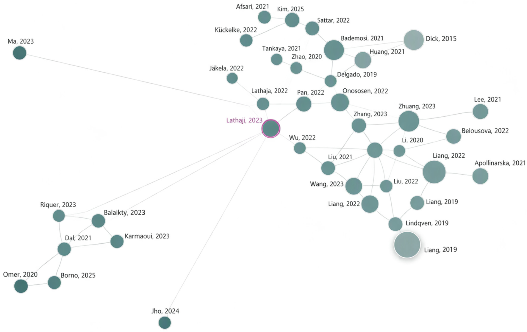


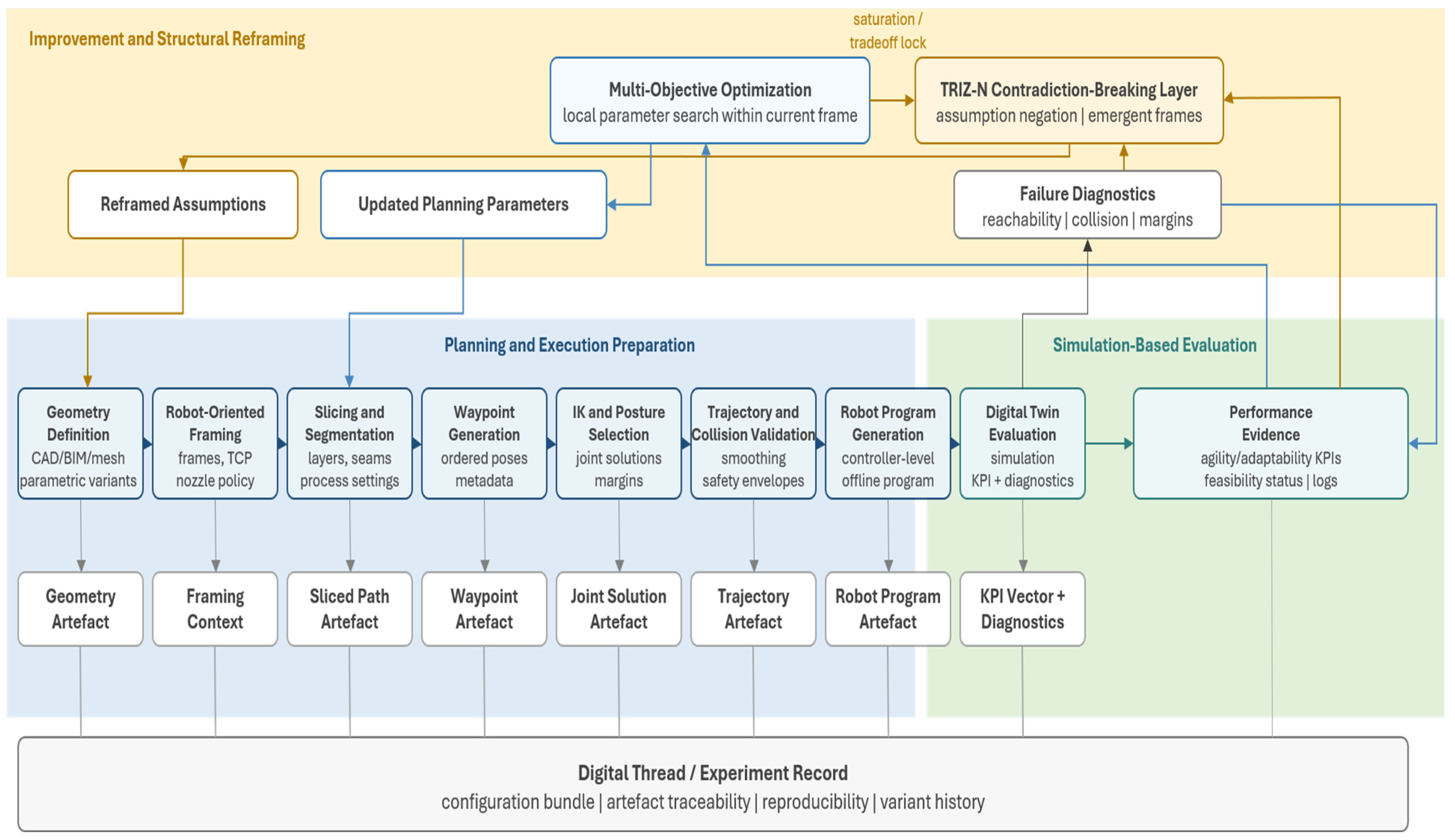


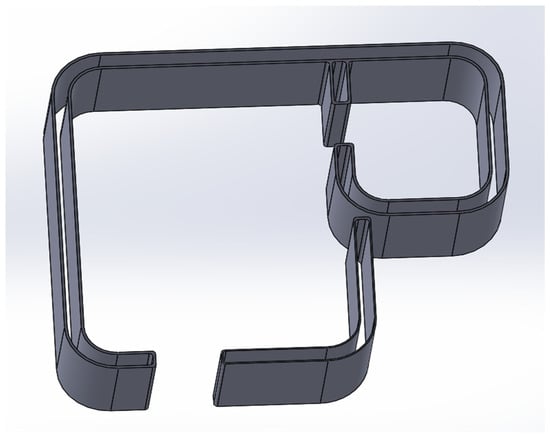
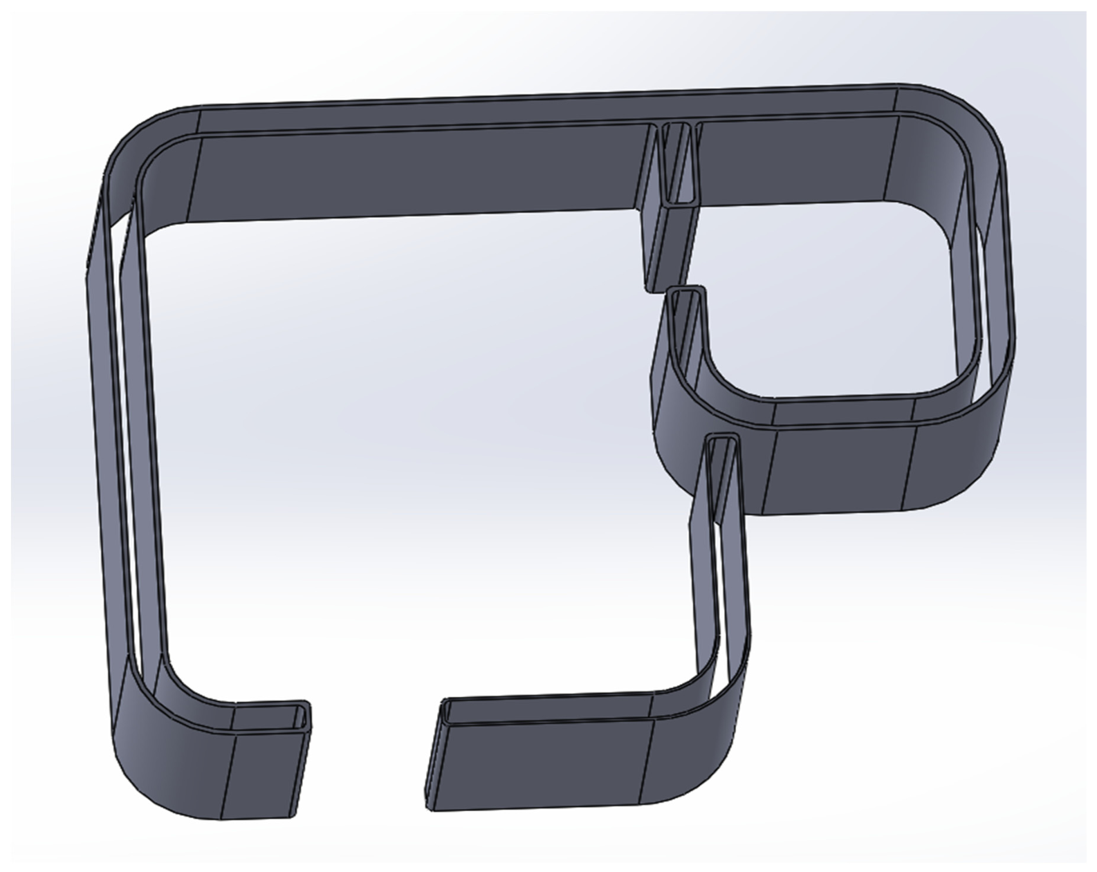
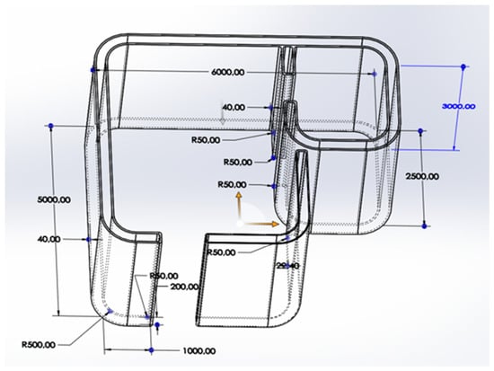
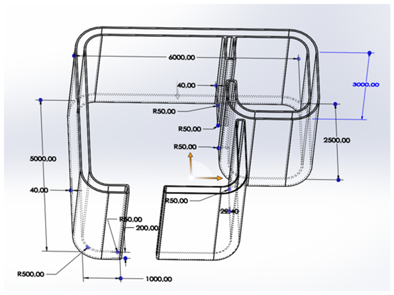
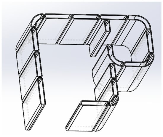
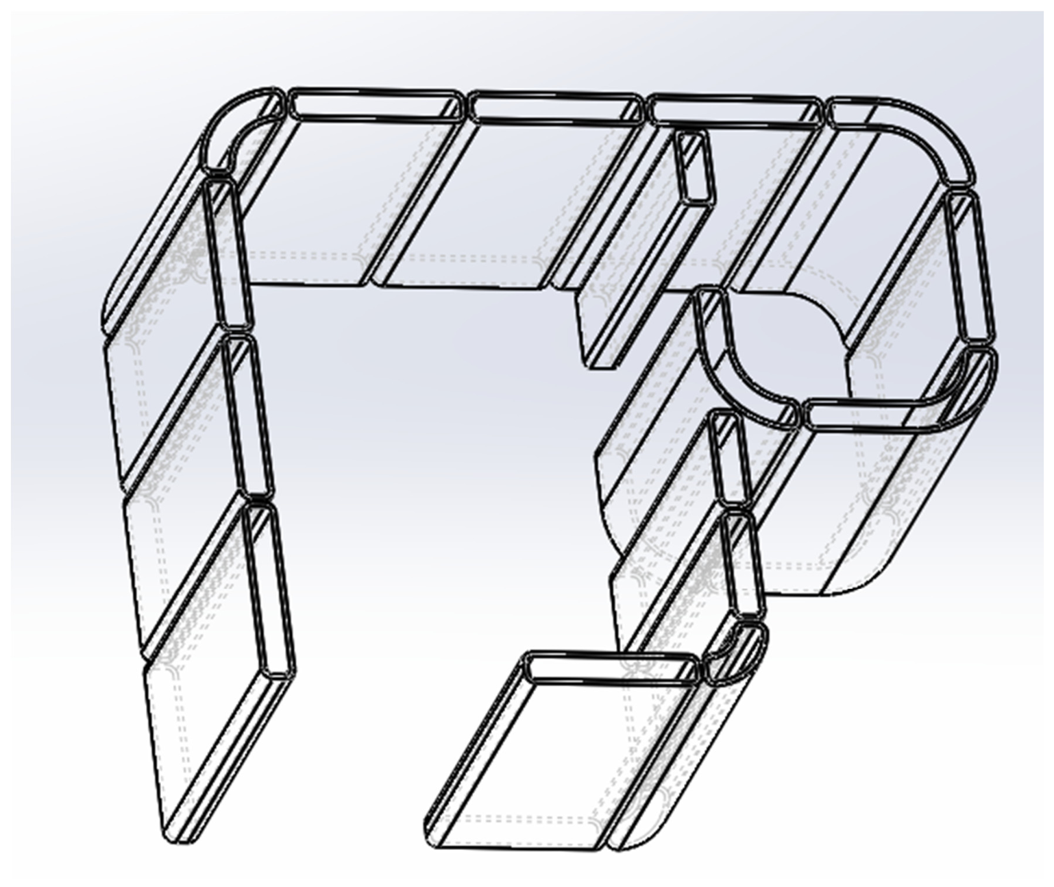
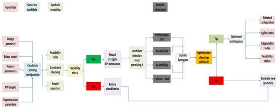
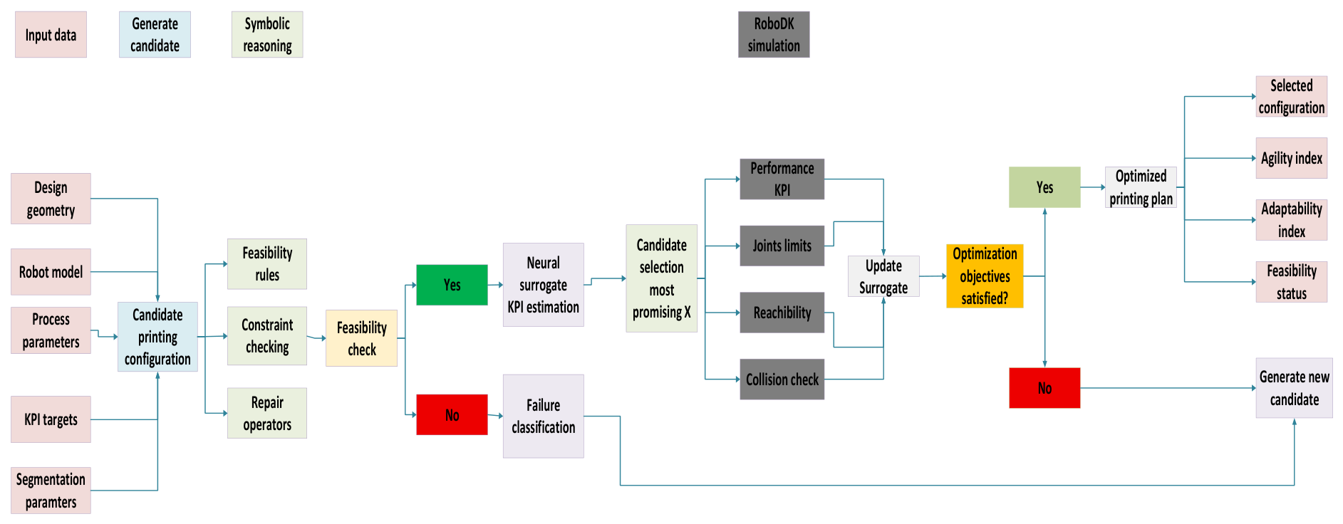


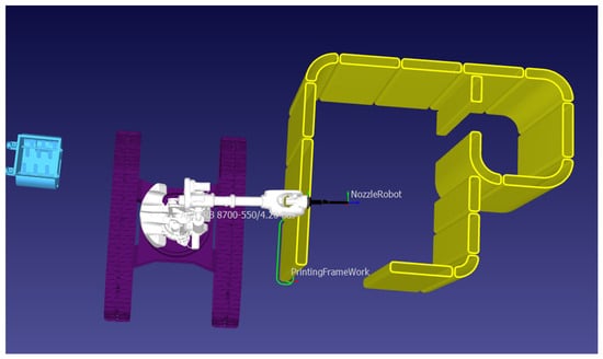
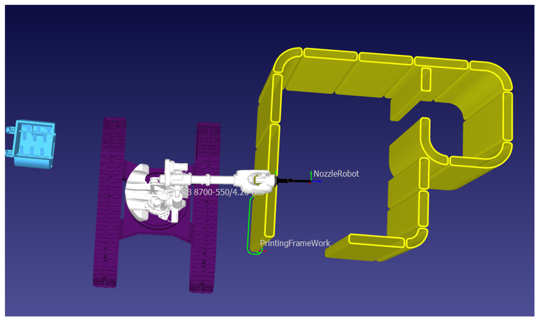
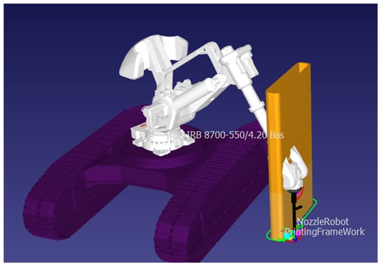
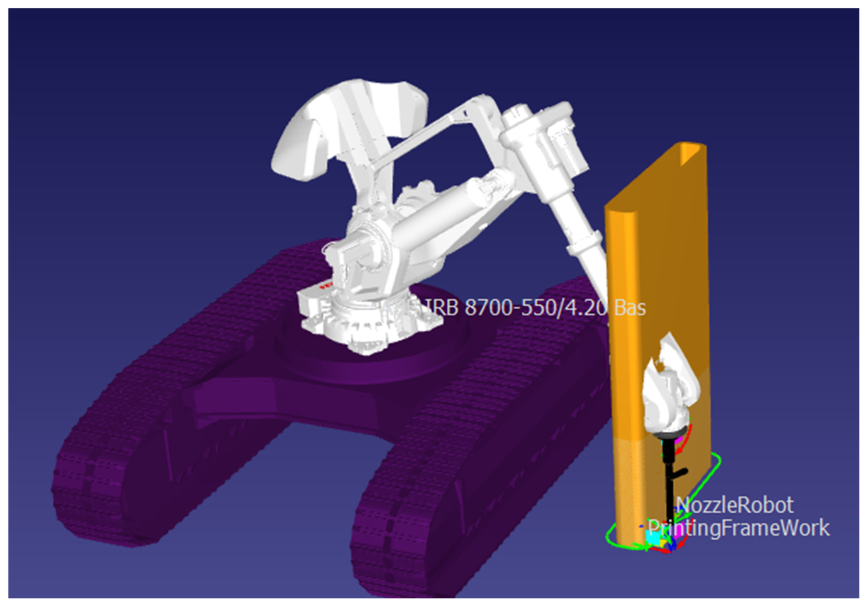



Disclaimer/Publisher’s Note: The statements, opinions and data contained in all publications are solely those of the individual author(s) and contributor(s) and not of MDPI and/or the editor(s). MDPI and/or the editor(s) disclaim responsibility for any injury to people or property resulting from any ideas, methods, instructions or products referred to in the content. |
© 2026 by the authors. Licensee MDPI, Basel, Switzerland. This article is an open access article distributed under the terms and conditions of the Creative Commons Attribution (CC BY) license.