Abstract
This paper proposes the use of cross-laminated timber (CLT) panels in conjunction with back-to-back cold-formed steel (CFS) channel or angle sections in combination with laminated veneer lumber (LVL) beam, for composite CFS-timber beams. Under a hogging and sagging moment, part of the CLT panel will act compositely with CFS-LVL in order to resist compression, while the lower part of CFS-LVL web will be in tension. Whilst shear lag effects have been well-researched for concrete-steel composite beams, there has been little research on this for CLT panels working with CFS-LVL sections. In this paper, the finite element method (FEM) is used to determine the effective flange width (FFW) for CFS-timber beams. In conclusion, the obtained result has shown that the EFW increases with any changes that lead to an increase in the ratio of the transverse layer’s depth to the longitudinal layer’s depth. Moreover, combinations of CFS sections with LVL have significantly resulted in the depth-of-beam decrease.
1. Introduction and Literature Review
This paper proposes a CFS-timber composite T-section beam that uses a cross-laminated timber (CLT) panel fastened to back-to-back cold-formed steel (CFS) channel sections or angle sections in combination with laminated veneer lumber (LVL) beam (Figure 1).
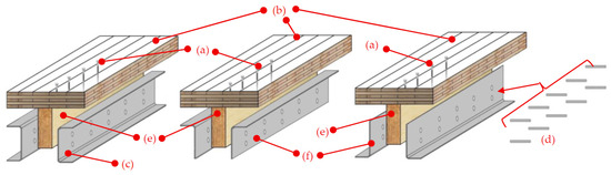
Figure 1.
Isometric view of the CFS-timber composite beams (CLT panel and composite LVL and CFS channel or angle section beam). (a) Screw, (b) CLT panel, (c) CFS channel beam, (d) bolt, (e) LVL beam, (f) CFS unequal angle beam.
The CLT panel plays the role of floor which is supported by the joists fabricated with LVL beams which are made stronger by CFS. Cold-formed steel in combination with engineered wood products in case of a flooring system can be an attractive option for hybrid commercial and residential constructions due to their high strength-to-weight ratio [1]. The CLT panels were simply connected by screws to the LVL beam, which are highly conventional in timber structures. Additionally, there is a wide range of options such as rivet, nail, and screw connections to simply attach thin and light CFS members to the timber part. For instance, as shown in Figure 1, the cold-formed steel sections are connected to LVL beam with bolted connection. The higher strength of cold-formed steel compared to LVL beam provides architects with greater flexibility, allowing designs that incorporate less depth of the flooring system with longer spans and other architectural features.
As shown in Figure 2, different combinations of the CLT panel, LVL beams, and CFS sections can be considered in order to provide various composite cross-sections of cold-formed steel-timber T-section beams. Based on the availability of the section in the construction market, various combinations provide different possibilities of connections between components like timber to CFS or structural elements like beam to column and floor to wall with bolts, screws, or rivets.
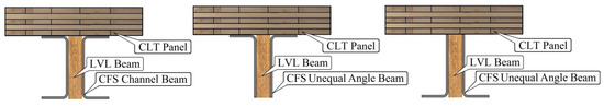
Figure 2.
Various combinations of CFS-timber composite beams.
Engineered timber products such as CLT and LVL are manufactured in plants across New Zealand. They have relatively higher load bearing and structural strength of timber. CLT is a relatively newly engineered timber product, first produced in 1999, after few years of initial development in Austria. It is a high-performance wood product, made of ordinary boards, usually of lower grades, glued together in a cross layered fashion, and typically showing a symmetric layout (Figure 3). Notable reduction in construction time with less labors cost and lighter weight compared to other engineered wood products such as LVL make the CLT panel extremely desirable for designers and building owners. The timber boards are made from Radiata Pine, a tree which is grown commercially [2,3,4]. Laminate veneer lumber (LVL) is an engineered wood composite made from rotary peeled veneers, glued with a durable adhesive, and laid with a parallel grain orientation to form long continuous sections (Figure 4) [2,5,6].
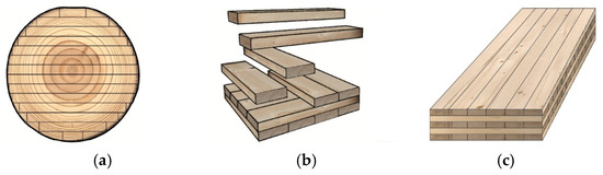
Figure 3.
Typical procedure of CLT production; (a) sawing log, (b) arranging boards, (c) final CLT product.
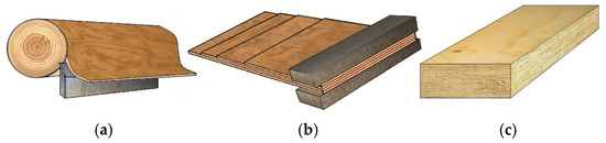
Figure 4.
Steps of LVL production; (a) peeling log and cutting, (b) pressing, (c) final LVL product.
Cold-formed steel sections are rolled from a galvanized steel coil which is bent into shape to suit the required section geometry. The process consists of pairs of rolls which progressively form strips into the final required shape (Figure 5). During cold-forming, cold working increases the yield stress of the steel by a process known as strain hardening. Cold-formed steel sections which are typically available in the market vary in depth from 60 to 400 mm, with a range of sheet thicknesses between 1.2 and 3 mm.
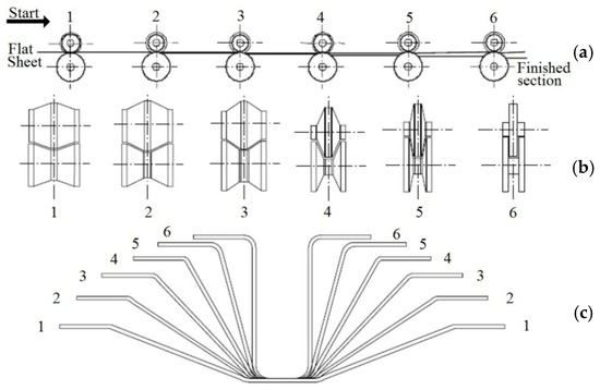
Figure 5.
Steps of cold formed section production: (a) stages in forming simple section, (b) rolling shape at each stage, (c) profile at each stage. The numbers indicate the sequential forming steps (passes) in the cold-forming process, from the flat sheet to the final section.
Recent studies on steel-timber composite beams highlight their ability to combine the strength and stiffness of steel with the sustainability of timber. Experimental work demonstrates improved load distribution and connection performance [7,8], while numerical modeling provides insight into effective flange width and stress-transfer mechanisms [9].
Although engineered wood products are an environmentally friendly natural composite material with significant structural qualities, like excellent strength-to-weight ratio compared to hot rolled steel and concrete, they are produced in large sections compared with cold-formed steel sections. Therefore, the proposed composite section of timber and cold-formed steel has an economical position to minimize the use of timber martial without neglecting its environmental and structural advantages. In a CFS-timber composite section, in-plane shear strain in the CLT panel which acting as a flange in the composite T-section beam under applied bending causes the longitudinal displacements in the parts of CLT panel remote from the CFS-LVL web to lag behind those near the CFS-LVL web, which this phenomenon named share lag [10]. This phenomenon leads to unrealistic estimation of stresses and strains when the simple beam theory has been used [11]. Determining the effective flange width influences the amount of moments, shears, torques, and deflections. Incorporating the effective flange enables simple beam theory to be used for analysis and design [10]. In steel-concrete composite sections, the effective flange width concept has been used widely in international design specifications, such as AISC (LRFD:13.1), the Canadian code (CSA: S17.4), and the Euro code (2000). Interestingly, in all of them shear lag effect is taken into account. Simplified effective flange width formulas are summarized in Table 1 [12].

Table 1.
Effective width be formulas for steel-concrete beams in various design codes.
Design codes provide a simple design procedure. Comparing the Canadian specification to other standards, the main advantage is simplicity. For example, only one formula is required to calculate the effective flange width for the concrete slab on I and box steel girders [13].
Many analytical studies of shear lag in stiffened thin plates and steel-concrete composite beams have been conducted to predict their behavior and determine the effective flange width. In these studies, an in-plane plate was assumed for the slabs and simple beam bending behavior for the beams is assumed [10,14,15,16]. In addition, orthotropic plate equations were used to consider the effective flange width of the steel-concrete composite I-beams after yielding [10,17]. In multi-span continuous beams, the beam would be subject to sagging or hogging bending moments. Although there are minor differences in the size of the effective flange of steel-concrete T-section beams under sagging and hogging bending moments, the concept has nevertheless been investigated by many researchers [18,19]. Moreover, with the rapid development of computer technology, composite beams could be analyzed more efficiently under various loading conditions and different geometries of beams. In addition, the finite element method has been used to consider the effective flange width of box girders [10,11,20]. Also, the finite element method can be used for parametric studies towards considering the effect of span length on the effective flange width for simple span bridges [11,21]. Table 2 shows various formulas for the effective flange width.
Table 2.
Effective width formulas based on theoretical and experimental studies.
While there have been a large number of studies for benefits of steel-concrete composite structures, there is a lack of information for the effective flange width of CFS-timber composite beams. The objective of this study is to investigate the behavior of simply supported composite CFS-timber composite beams within the elastic range. The accuracy of the effective flange width size in CFS-timber composite beam has a major effect on the design of the structural components. A comprehensive finite element analysis has been carried out to determine the effective flange width.
2. Shear Lag and Effective Flange Width
In the simple beam theory, it is assumed that the stresses are constant throughout the width of the beam. This assumption is appropriate for the thin web beam. Therefore, the strain profile at any particulate cross section varies linearly throughout the depth of the section. In wide CLT flanges, the stresses are not uniform. This variation in stress is due to action of in-plane shear strain in the plate, which is termed shear lag (Figure 6) [22]. The discussion presented here is purely theoretical and conceptual, based on established beam theory and design principles, and does not involve experimental materials or testing equipment.
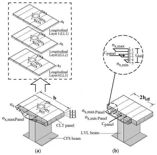
Figure 6.
Concept of effective flange width. (a) actual stress distribution. Please note “b” is width of CLT slab; (b) uniform stress distribution within effective flange width.
Shear lag is a well-known phenomenon in composite sections. It occurs when in-plane shear strain in the flange of a girder under applied bending causes longitudinal displacements. As a result, the parts of the flange away from the webs lag behind those near the webs. When simple beam theory is used, this phenomenon can result in inaccurate estimation of the displacements and stresses in the extreme fibers of composite sections. By substituting an effective flange width with a suitable reduced uniform stress block, the shear lag effects can be accounted for and elementary beam bending theory can be applied.
In a cold-formed steel-timber composite T-section beam under sagging, part of the CLT panel will act as the flange for the CFS-LVL girder which resists compression. The three-dimensional pattern of normal stress at distance x of each longitudinal layer of CLT panel, σx = σx (y,z), is represented by its maximum value (σx,max) in Figure 4. This relationship is expressed in Equations (4) and (5). The real force in the one side of the flange is calculated by double integration of the real stress distribution for each longitudinal layer of the CLT panel. By dividing the calculated force to the thickness of the relative longitudinal layer and the maximum stress in the corresponding region, the effective flange width for the layer will be obtained. The overall effective flange width for the CFS-timber T-section beam is derived by the summation of the evaluated flange widths for each layer.
where be is the one-side effective flange width, 2b is the girder spacing, and σx1, σx2, σx3 are the normal stresses in the corresponding direction in longitudinal layers 1, 2, and 3 of the CLT panel, which is illustrated in Figure 3. As shown in Equations (4) and (5), the effective flange width is defined at a given distance x from the span, which means that beff is a function of x [22,23].
3. Test Setup and Finite Element Simulation
A full-scale timber composite beam was tested at the University of Auckland, and the experimental findings were later applied to calibrate a numerical model. The specimen, shown in Figure 7, consisted of a 7 m-long LVL beam (300 mm wide × 600 mm deep) combined with a CLT flange panel. The flange was a five-layer CLT element measuring 6 m in length, 2 m in width, and 200 mm in thickness. Mechanical connection between the two components was provided by forty-eight self-tapping screws, 550 mm in length and 11 mm in diameter, arranged at a 45° angle to improve composite interaction. The beam was subjected to a bending test using an MTS actuator capable of delivering the service-level loads required for the study (laboratory testing equipment available at the University of Auckland, Auckland, New Zealand) (refer to Figure 7a).
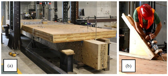
Figure 7.
(a) The timber composite beam test setup, (b) screwing the CLT slab to the LVL beam.
The finite element program ABAQUS version 6.13-3 was used to determine the stress distribution pattern in CLT for simply supported CFS-timber composite beams. The eight-noded element C3D8R, which is a linear 3D solid element, was used. The material properties of timber from three-point experimental bending tests for CLT panel and LVL beam are summarized in Table 3 (Figure 8) [5,24,25]. For cold-formed steel, the values for Young’s modulus and Poisson’s ratio are 210 GPa and 0.3, respectively.
Table 3.
Material properties of the CLT [12,26,27,28].
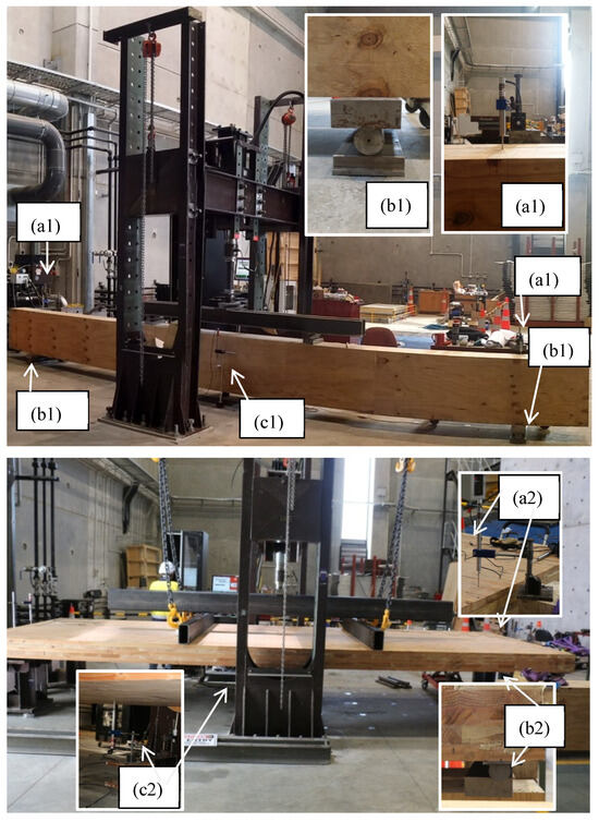
Figure 8.
Four-point bending test setup for measuring the LVL modulus of elasticity. (a1) LVDT at the hinge support, (b1) hinge support, (c1) LVDT at the mid-span. Four-point bending test setup for measuring the CLT modulus of elasticity. (a2) LVDT at the roller support, (b2) roller support, (c2) LVDT at the mid-span.
To represent screw connection between CLT panel and LVL beam, the numerical assembly of the panel and the beam were connected by a series of “bar” elements which were embedded in the CLT panel and the LVL beam. The experimental test setup which was used to verify the simulation of screws connection between CLT panel and LVL beam is shown in Figure 7.
Additionally, tie contact was used to represent the fully composite action between the CFS and LVL in web of CFS-timber composite beam. Figure 9 shows the general arrangement of the finite element model.
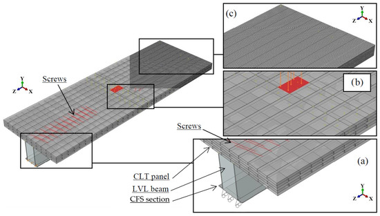
Figure 9.
General arrangement of the finite element model: (a) boundary conditions (loads and supports), (b) loading area, and (c) mesh. The red-colored area highlights the loading region and the screw connection.
The accuracy of the numerical approach was assessed through several comparisons with experimental results. Specifically, mid-span deflections of both the T-section and its individual components (the CLT panel and the LVL beam) were checked, the relative slip between the CLT and LVL was recorded at 1 m intervals along the beam span, and the effective flange width obtained from the model was compared against test data (see Table 4 and Table 5 and Figure 10). The strong correlation observed across these parameters demonstrates that the model provides sufficient accuracy for determining the effective flange width of the timber composite beam [6,12].
Table 4.
Comparison of the experimental and numerical results for mid-span deflection.
Table 5.
Comparison of the experimental and the numerical slip results.
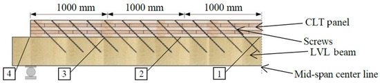
Figure 10.
Slip monument for every 1 m along the span of the timber composite beam (elevation). The numbered labels (1–4) represent equally spaced measurement positions at 1 m intervals measured from the beam mid-span.
4. Results and Discussions
CFS-timber composite beams with two different thicknesses of longitudinal and transverse layers with a similar arrangement of five layers CLT panels which were made up of boards with 8 and 8 GPa modules of elasticity were analyzed to investigate the influence of thickness on the effective flange width and behavior of T-section beams.
The numerical results are illustrated in Figure 11 and Figure 12 for simply supported beams under uniformly distributed load. Table 6 provides a summary of the relatively effective flange width values for Figure 11 and Figure 12.
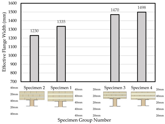
Figure 11.
Effect of transverse layer thickness on effective flange width of the CFS-timber composite beams.
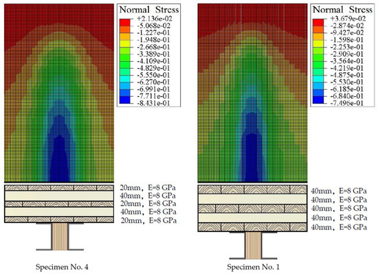
Figure 12.
Comparing stress normal distribution pattern in CFS-timber composite beams (top view of half span) (units are Newtons and millimeters).
Table 6.
Specifications and effective width flange (mm) of the CFS-timber composite beams.
As can be seen in Figure 11 and Table 6, the effective flange width increases when the ratio of the transverse layer’s depth over the longitudinal layer’s depth increases. For example, the effective flange width of the model which consisted of a CLT panel with five layers of 20 mm boards (Specimen No. 3 in Table 6) increased by 2% when the transverse layers were replaced by boards with 40 mm of thickness (Specimen No. 4 in Table 6). Furthermore, the normal stress distribution pattern in Figure 12 clearly shows that the effective width flange of the T-section specimen which comprised a CLT panel with five layers of 40 mm board (Specimen No. 1 in Table 6) was escalated by about 13% from 1335 mm to 1498 mm when 40 mm longitudinal layers were replaced by 20 mm longitudinal layers (Specimen No. 4 in Table 6). In terms of layer thickness in the CLT panel, the maximum increase in effective flange width size was observed when 40 mm longitudinal layers and 20 mm transvers layers in Specimen No. 4 were replaced by 40 mm and 20 mm thickness of boards, respectively (Specimen No. 2 and No. 4 in Table 6). This arrangement led to a 268 mm growth in size of the effective flange width, which is equal to 22% and improves in shear lag performance.
Moreover, the influence of span length from the supports on the effective flange width distribution has been examined. Figure 13 illustrates the variation in effective flange width size across the beam span. Similarly, the results showed when depth of transverse layers over longitudinal layers increase, shear lag performance enhances throughout span.
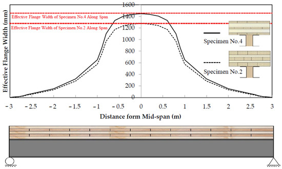
Figure 13.
Variation in effective flange width of the CFS-timber composite beams through the span.
Regarding the effect of the CLT material properties on the effective flange width, Figure 14 and Figure 15 indicate that the use of a CLT panel with lower modulus of elasticity led to a decrease in size of effective flange width. For instance, as shown in Figure 14, when on average the CLT panel modulus of elasticity decreased from 8 GPa to 6 GPa, the size of the effective flange width dropped by 4% on average. Moreover, normal stress distribution in Figure 14 shows a similar effect for changing the modulus of elasticity in CLT panels. This implies that the size of the effective flange width slightly decreased when the modulus of elasticity in Specimen 1 decreased from 8 GPa to 6 GPa; it increased from 1335 mm to 1287 mm (Specimen No. 1 and 5 in Table 6 and Figure 15). Also, Table 6 shows that when the layers of CLT panel with 8 GPa and 6 GPa modulus of elasticity are reversed in Specimen No. 15 and No. 16, the effective width flange increases to 105 mm. This increase confirms that the material properties of the transverse layers in CLT panels play an important role in determining effective width flange size in the CFS-timber composite beams.
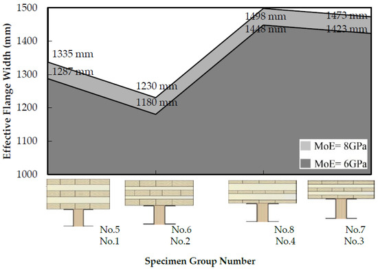
Figure 14.
Effect of CLT material properties on effective flange width.
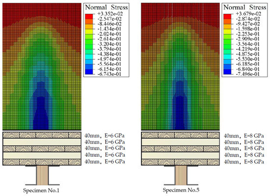
Figure 15.
Comparing normal stress distribution patterns in CFS-timber composite beams (top view of half span) (units are Newton and millimeter).
In terms of beam span length effect on effective flange width, the CFS-timber composite beams were modeled in three different lengths. The results in Table 6 and Figure 16 show that increase in span size did not alter the shear lag performance and effective flange width of the CFS-timber composite beams. For instance, when the span of Specimen 1 was increased from 6 m (Table 6) to 8 m and then 10 m (Specimens 9 and 20 in Table 6) the effective flange width of the specimens increased by 1.79% and 0.78%, respectively, which is a negligible improvement.
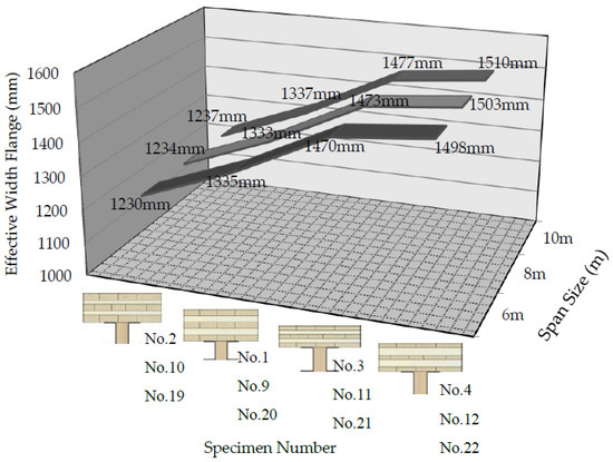
Figure 16.
Effect of span size layer thickness on effective flange width.
5. Conclusions
The preliminary finite element study of hybrid CFS-timber composite T-section beams with actual geometry and material properties has been conducted to provide values of effective flange width. The finite element software ABAQUS was employed to carry out the finite element analysis for predicting the behavior of the hybrid CFS-timber composite T-section beams and it can provide data that will be required in a future experimental test. The effective flange width of CFS-timber composite beams was studied extensively by numerical models consisting of various arrangements, thicknesses, and material properties. It has been shown that the effective flange width increases with any changes that lead to an increase in the ratio of the transverse layer’s depth to the longitudinal layer’s depth. Although the combination of CFS section leads to a reduced use of LVL, which is a relatively expensive wood product, analyses have shown that this reduction in combination with CFS-LVL beam had a negligible effect on effective flange width size as long as neutral axis remains in the beam. Moreover, the analyses specimens in three different spans lengths have shown that span size does not change effective flange width of specimens. Finally, the maximum improvement in effective flange width size in hybrid CFS-timber composite beams is a result of using CLT panel with maximum ratio of the transverse layer’s depth to the longitudinal layer’s depth and a higher modulus of elasticity.
Author Contributions
Conceptualization, R.M.; methodology, R.M.; software, R.M.; validation, R.M. and A.H.; formal analysis, R.M.; investigation, R.M. and A.H.; resources, R.M.; data curation, R.M.; writing—original draft preparation, R.M.; writing—review and editing, R.M., A.H., Z.F. and J.B.P.L.; visualization, R.M. and S.M.; supervision, R.M.; project administration, R.M. All authors have read and agreed to the published version of the manuscript.
Funding
This research was carried out independently by the authors and did not receive any external funding, financial contributions, or research grants from public institutions, commercial organizations, or not-for-profit bodies at any stage of the study.
Data Availability Statement
Detailed information related to the numerical modeling, experimental testing, and comprehensive literature review conducted in this study is provided in the referenced articles and the associated doctoral thesis by Reza Masoudnia. Further technical information may be obtained from the corresponding author upon reasonable request.
Acknowledgments
The authors would like to thank the laboratory technicians Mark Byrami and Andrew Virtue for their contribution in preparing the test setup. Gratitude is extended to Milad Naghibi, Daniel Lowe, and Soroosh Haji Hosseinnejad for providing ideas and support with ABAQUS. Finally, the authors thank photographer and graphic designer Nariman Valizadeh and Navid Masoudnia for providing great photos and figures. This technical paper was developed to demonstrate the great structural potential of timber composite beams constructed using CLT panels for structural applications. Please note that it is the responsibility of the project engineer, designer, or specifier to ensure the presented results are fit for their project purpose and not to rely solely on numerical analyses.
Conflicts of Interest
The authors declare no conflicts of interest and received no funding for the development of this paper. The funders had no role in the design of the study; in the collection, analysis, or interpretation of data; in the writing of the manuscript; or in the decision to publish the results. This technical paper was prepared to demonstrate the significant structural potential of timber composite beams constructed using CLT panels for structural applications. It is the responsibility of the project engineer, designer, or specifier to determine the suitability of the presented results for their specific project and not to rely solely on the numerical analyses provided.
References
- Kyvelou, P.; Gardner, L.; Nethercot, D.A. Composite Action Between Cold-Formed Steel Beams and Wood-Based Floorboards. Int. J. Struct. Stab. Dyn. 2015, 15, 1540029. [Google Scholar] [CrossRef]
- Masoudnia, R.; Quenneville, P. Stub girder flooring system for timber construction. In Proceedings of the World Conference on Timber Engineering, Quebec City, QC, Canada, 10–14 August 2014. [Google Scholar]
- Popovski, M.; Karacabeyli, E. Seismic behaviour of cross-laminated timber structures. In Proceedings of the World Conference on Timber Engineering, Auckland, New Zealand, 15–19 July 2012. [Google Scholar]
- Pearson, H.; Evernden, M.; Harris, R. Analysis of engineered timber panels using a strut and tie model for use in folded plate structures and deep beams. Eng. Struct. 2012, 9, 344–353. [Google Scholar]
- Masoudnia, R.; Quenneville, P. Stub Girder Flooring System for Timber Construction; Provisional Report; The University of Auckland: Auckland, New Zealand, 2013. [Google Scholar]
- Masoudnia, R.; Hashemi, A.; Quenneville, P. Evaluation of effective flange width in the CLT composite T.-beams. In Proceedings of the World Conference on Timber Engineering (WCTE 2016), Vienna, Austria, 22–25 August 2016. [Google Scholar]
- Dias, A.M.P.G.; Skinner, J.; Crews, K.; Riggio, M. Mechanical performance of timber–steel hybrid connections. Eng. Struct. 2016, 112, 196–207. [Google Scholar]
- Fragiacomo, M.; Lukaszewska, E. Design model for steel–timber composite beams. J. Struct. Eng. 2011, 137, 785–794. [Google Scholar]
- Chen, Z.; Yeoh, D.; Guan, Z.W. Finite element analysis of composite steel–timber beams with screw connections. Constr. Build. Mater. 2019, 208, 187–198. [Google Scholar]
- Chiewanichakorn, M.; Aref, A.J.; Chen, S.S.; Ahn, I. Effective flange width definition for steel-concrete composite bridge girder. J. Struct. Eng. 2014, 130, 2016–2031. [Google Scholar] [CrossRef]
- Chen, S.S.; Aref, A.J.; Chiewanichakorn, M.; Ahn, I. Proposed effective width criteria for composite bridge girders. J. Bridge Eng. 2007, 12, 325–338. [Google Scholar] [CrossRef]
- Masoudnia, R.; Hashemi, A.; Quenneville, P. Predicting the Effective Flange Width of a CLT Slab in Timber Composite Beams. J. Struct. Eng. 2018, 144, 04018084. [Google Scholar] [CrossRef]
- Alsarraf, M.A.; El Din, H.S. Effects of Web Openings on the Effective Slab Widths in Composite Steel Beams. In Proceedings of the ICCAE, Paris, France, 21–22 July 2014; pp. 27–28. [Google Scholar]
- Winter, G. Stress Distribution in the Equivalent Width of Flanges of Wide, Thin-Wall Steel Beams; National Advisory Committee for Aeronautics: Hampton, VA, USA, 1940. [Google Scholar]
- Schade, H.A. The Effective Breadth of Stiffened Plating Under Bending Loads; Society of Naval Architects and Marine Engineers: Alexandria, VA, USA, 1951. [Google Scholar]
- Timoshenko, S.; Goodier, J.; Abramson, H.N. Theory of elasticity. J. Appl. Mech. 1970, 37, 888. [Google Scholar] [CrossRef]
- Heins, C.P.; Fan, H.M. Effective composite beam width at ultimate load. J. Struct. Div. 1976, 102, 2163–2179. [Google Scholar] [CrossRef]
- Adekola, I. Effective widths of composite beams of steel and concrete. Struct. Eng. 1968, 46, 285–289. [Google Scholar]
- Aref, A.J.; Chiewanichakorn, M.; Chen, S.S.; Ahn, I. Effective slab width definition for negative moment regions of composite bridges. J. Bridge Eng. 2007, 12, 339–349. [Google Scholar] [CrossRef]
- Moffatt, K.R.; Dowling, P.J. British shear lag rules for composite girders. J. Struct. Div. 1978, 104, 1123–1130. [Google Scholar] [CrossRef]
- Nassif, H.; Abu-Amra, T.; El-Tawil, S. Effective flange width criteria for composite steel girder bridges. In Proceedings of the Transportation Research Board 84th Annual Meeting, Washington, DC, USA, 9–13 January 2005. No. 05-2477. [Google Scholar]
- Ahn, I.; Chiewanichakorn, M.; Chen, S.S.; Aref, A.J. Effective flange width provisions for composite steel bridges. Eng. Struct. 2004, 26, 1843–1851. [Google Scholar] [CrossRef]
- Castro, J.; Elghazouli, A.; Izzuddin, B. Assessment of effective slab widths in composite beams. J. Constr. Steel Res. 2007, 63, 1317–1327. [Google Scholar] [CrossRef]
- Masoudnia, R. Feasibility of Cross Laminated Timber Panel for Bridges Application: Preliminary Experimental, Numerical and Analytical Study. In Proceedings of the World Conference on Timber Engineering, Brisbane, Australia, 22–26 June 2025. [Google Scholar]
- Masoudnia, R.; Masoudnia, S.; Hashemi, A.; Quenneville, P. Numerical Investigation of CLT Composite Double T-Beams. In Proceedings of the World Conference on Timber Engineering, Brisbane, Australia, 22–26 June 2025. [Google Scholar]
- Gagnon, S.; Pirvu, C. CLT Handbook: Cross-Laminated Timber; FPInnovations: Montréal, QC, Canada, 2011. [Google Scholar]
- Buchanan, A.H.; New Zealand Timber Industry Federation. Timber Design Guide; New Zealand Timber Industry Federation: Wellington, New Zealand, 1999. [Google Scholar]
- Masoudnia, R. Improvements to Timber Composite Beams. Provisional Patent No. 731,716, 2017.


Disclaimer/Publisher’s Note: The statements, opinions and data contained in all publications are solely those of the individual author(s) and contributor(s) and not of MDPI and/or the editor(s). MDPI and/or the editor(s) disclaim responsibility for any injury to people or property resulting from any ideas, methods, instructions or products referred to in the content. |
© 2026 by the authors. Licensee MDPI, Basel, Switzerland. This article is an open access article distributed under the terms and conditions of the Creative Commons Attribution (CC BY) license.