


Abstract
Not all data derived from structural analysis or experimental testing can be effectively encoded using Industry Foundation Classes (IFC) properties or attributes, even if custom-made. In many cases, visual outputs—such as images—represent the only practical means of conveying complex analytical results. However, the current literature provides limited guidance on systematically integrating images within IFC models, with practitioners often relying on external formats or auxiliary technologies. This study investigates how the IFC standard supports the visualization of textures applied to geometric entities, focusing on the relevant classes and their interrelationships. Building on this theoretical framework, a prototype is developed within the Bonsai environment, leveraging Blender 4.5 and its add-on architecture. The prototype enables the creation of planar geometries in 3D space and the application of image-based textures, enabling visual information to be associated with IFC geometry through standard texture-mapping entities and an external image reference. A case study involving the visualization of structural testing results demonstrates the approach. By keeping the visual output registered to the model geometry, the approach has the potential to enhance analytical interpretation, communication among stakeholders, and data visualization within the built environment domain.
1. Introduction
In structural and civil engineering, a growing share of the information relevant to interpreting the behavior of structures is now produced in an intrinsically visual form. This evolution has made images not merely illustrative material, but often the most effective means of conveying the complexity of an analytical or experimental result.
Despite this centrality of visual outputs, the digital tools currently used to manage the life cycle of a structure struggle to natively accommodate them. Building Information Modeling (BIM) represents the most widespread approach for centralizing geometry, properties, and project information within a single shared digital model [1], yet interoperability remains the main limitation of its implementation in the structural domain [2]. The outputs of structural analyses, in particular, are not natively incorporated into the model and often remain in separate documents or external software [3], breaking information continuity among designers, structural engineers, inspectors, and clients [4]. Indeed, not all data derived from structural analysis or experimental testing can be effectively encoded through IFC properties or attributes, even when custom-made: in many cases, images represent the only practical means of conveying complex analytical results. Yet current literature provides limited guidance on how to systematically integrate images within Industry Foundation Classes (IFC) models, and practitioners often resort to external formats or auxiliary technologies.
This study investigates how the IFC standard supports the visualization of textures applied to geometric entities, with particular attention to the relevant classes and their relationships. Building on this theoretical framework, a prototype is developed within the Bonsai environment, leveraging Blender and its add-on architecture: the prototype enables the creation of planar geometries in 3D space and the application of image-based textures, thereby associating visual information with IFC geometry through standard texture mapping and an external image reference. A case study on the visualization of structural testing results demonstrates the proposed approach. Although the paper provides a summary of the current state of the art, its main contributions lie in providing a clear and comprehensive explanation of how the relevant IFC can be used to associate textures with tessellated geometries, and in developing a prototype capable of implementing this texture mapping within an IFC model.
The remainder of the paper is organized as follows. Section 2 provides the background, presenting evidence on the visual nature of data in the structural domain and the state of the art on the integration of images within BIM/IFC models. Section 3 describes the proposed methodology and the materials used. Section 4 presents the case study and results. Section 5 discusses the findings, and Section 6 draws the conclusions.
2. Background
2.1. The Visual Nature of Structural Data
A growing share of the information useful for understanding the behavior of structures, in the civil and structural engineering domain, is now produced in visual form. Many relevant results, such as stress maps, deformed shapes, crack patterns, and images of specimens during testing, are in fact intrinsically spatial: their information does not reside in a single value, but in the way a quantity is distributed, localized, and evolves across the surface of an element.
This visual nature emerges across a range of contexts. Laboratory tests often yield information that cannot be reduced to a single measured value, such as the failure of an element [5], its deformation under load [6], or the formation of a crack pattern [7], whose complete characterization requires a visual representation. Finite element method (FEM) outputs are likewise spatial, as the mechanical response of a component depends on how stress and strain states are distributed in space rather than on a single synthetic value [8]. Finally, remote inspection outputs such as RGB imagery, infrared thermography, and 3D reconstructions produce condition maps of cracks, delamination, and corrosion whose severity no tabular value could convey [9,10].
In all these contexts, then, the image is not merely a complement to numerical data but often constitutes its primary information carrier [11]: the ability to store it and associate it with the structural element to which it refers thus becomes an essential requirement for any environment that aims to manage information about a structure comprehensively.
However, the informative value of these images depends on their association with the structural element they refer to. A photograph alone does not reliably identify which component or face of a structure is affected [12], and even when computer vision detects damage in an image, its structural interpretation requires localizing that damage on the specific model component, with its known function and design role [13]. In practice, instead, visual records are frequently confined to standalone reports or spreadsheets rather than retained within a digital model, compromising the continuity and long-term accessibility of the data [14,15]. Anchoring images to the geometry of the elements they describe is therefore a precondition for their structural meaning—and it is precisely this anchoring that requires a standardized mechanism within the digital model, as discussed in the following section.
2.2. BIM, IFC and Images Integration
BIM currently represents the reference methodological approach for the digital management of the life cycle of a structure, from design to construction and through to operation and maintenance. Unlike purely geometric modeling, a BIM model organizes information according to an object-based structure, in which each element carries its own properties, relationships with other components, and project metadata, thus constituting a single information container rather than a mere three-dimensional representation. Within this framework, IFC [16] is the main open and neutral exchange standard, developed precisely out of the need to overcome proprietary formats, information silos, and the loss of interoperability between different disciplinary tools [17]. IFC does not define geometric entities alone, but a unified structure of objects, attributes, properties, and interrelationships, which makes it possible to represent physical elements, spaces, processes, and management information throughout design, construction, operation, and maintenance [18]. A substantial body of work therefore focuses on extensions and workflows that enrich IFC beyond geometry, from project metadata [19] to operation and maintenance (O&M) in infrastructure domains [20].
The application of textures to IFC entities opens up several concrete possibilities. The most immediate is to give the model a visually realistic appearance, narrowing the gap between the digital and physical world and making user interaction more intuitive [21,22]. A second use concerns the transfer of surface information from survey data to the model: in HBIM and scan-to-BIM contexts, textures generated from laser scanning and photogrammetry, or converted directly from the color of the point cloud, make it possible to document material condition, deterioration, and construction phases on as-is models [23,24]. A third use is the employment of textures as a carrier of diagnostic information within the model itself: defect images such as corrosion, delamination, or exposed reinforcement can be captured, processed, and associated with elements of an IFC-based BIM model, using the image to represent an analytical result and not merely the appearance of the material. Notably, however, when damage information is brought back into the IFC model, it is typically encoded through geometric and semantic constructs, such as triangulated damage meshes [25] or semantic representations reconstructed from point clouds [26]. The texture mechanism itself is rarely involved, confirming that the use of images as information carriers within IFC remains largely unexplored. Even so, the IFC schema does not yet provide all the entities and classes needed to manage this information comprehensively, lacking, for instance, parameters to specify how a defect progresses over time [14].
Despite its expressive power, IFC remains complex and unevenly implemented across software [27,28], with geometry encoded in heterogeneous representations that hinder reuse and downstream processing [29]. Within this structure, the IFC schema has long provided entities dedicated to the management of textures, that is, to the general mechanism that associates a 2D image with a 3D surface through an explicit geometric mapping [30]. Although the IFC schema explicitly defines entities and relationships for texture representation and mapping, support for these entities remains uneven across software applications. This implementation gap should be distinguished from the capabilities of the IFC schema itself, since individual applications may implement only a subset of the functionality available in IFC, depending on their supported exchange requirements and Model View Definitions (MVDs). Consequently, the inability of a given application to visualize a texture should not be interpreted as a limitation of the IFC schema, but rather as a limitation of the functionality implemented by that application [31]. Many software applications, in fact, do not export or retain textures in the IFC file [32] even when the source model contains them. This limitation is significant enough that some authors have had to develop external workflows—for instance, using IfcOpenShell 0.8.3. [33]—to associate image files with materials and project textures onto object faces outside the standard IFC exchange [31].
Several works in the literature do not use IFC to represent textures. For example [34] use a multi-layer Augmented Reality architecture that relies on IFC data repositories and Polygon File Format (PLY) extensions for images, textures, and point clouds. Other attempts to use IFC for VR [32] employ IFC as the base model but apply textures in a separate environment, visualizing them in Unity through a COLLADA (Collaborative Design Activity) file. Similarly, the application proposed in [35] for cultural heritage treats the IFC model and a separate 3D geometric model (OBJ) differently in order to display the textures. Also [13] start from an IFC and parse it using IfcOpenShell, and the geometry is rendered using Open3D.
Some works address the use of textures in relation to IFC. Reference [36] briefly discuss the relationships between IFC, but their treatment lacks sufficient detail and does not demonstrate the application of texture to any object. In earlier work, [37] show a texture applied to wall damage using XbimXplorer [38], but likewise do not explain in detail how this is implemented [39,40]; meanwhile, they provide a highly accurate description of the class relationships involved in applying texture to objects, yet without detailing how these relationships should be properly encoded, leaving readers to infer the implementation from the IFC specification itself. This work addresses this gap by providing a complete explanation of how to correctly implement and manage texture within an IFC model.
Overall, integrating images into 3D geometries within IFC is technically possible but remains a fragile and poorly standardized operation. Above all, the established uses are oriented toward visual rendering, whereas the only line of work truly close to the representation of analytical or experimental results, namely that on structural damage, remains vertical and tied to a specific application domain [12,13,14], and the IFC schema itself is not yet structured to support it systematically [18]. Even the most recent efforts to reintegrate structural analysis results into IFC models rely on extended schemas and tabular data structures rather than visual representations [41].
The potential of the texture mechanism as a vehicle for analytical and experimental outputs thus remains essentially unaddressed, and even its correct implementation within IFC lacks a documented account. This work addresses both gaps: it provides a complete explanation of how to correctly implement and manage texture within an IFC model, and it employs that mechanism to represent analytical and experimental results.
3. Materials and Methods
3.1. Materials
The materials employed in this work consist of three interconnected open-source tools. Blender [42] serves as the foundational 3D creation suite, offering a free and open-source environment for modeling and rendering; its capabilities can be further extended through the Blender API, which allows advanced users to write custom Python scripts and develop specialized tools tailored to specific workflows. Building on this platform, Bonsai [43] provides a free, open-source, and native IFC authoring environment, implemented as an add-on to Blender, designed to function as a comprehensive and truly native BIM authoring platform. Underlying Bonsai is IfcOpenShell [33], an open source IFC toolkit and geometry engine that enables the reading, writing, and modification of Building Information Models through IFC, a diverse digital language spanning design, construction, and beyond. IfcOpenShell offers both C++ and Python APIs, and is complemented by an ecosystem of associated tools, libraries, and command-line applications, among which Bonsai itself represents a graphical IFC authoring platform built directly on top of it. Together, these three tools form an integrated open-source pipeline, ranging from low-level IFC data manipulation to high-level, user-friendly BIM authoring within a 3D modeling environment. Among the available BIM authoring environments and IFC toolkits, this combination was selected because it is open source, well documented, and relatively accessible to users, while also enabling the development of custom functionalities and user interfaces within a native IFC environment.
3.2. Methodology
The methodology section describes the use of several IFC. These descriptions should not be interpreted as a comprehensive guide to the IFC schema that can be found on the official website [44], but rather as a detailed explanation of the fundamental concepts necessary to understand the logic underlying the application of textures to planar surfaces. To clarify the relationships among these classes, the authors employ graphical representations in which classes are depicted as light-blue charts, with rows corresponding to the attributes and relationships exposed by each class. Mandatory attributes are shown in bold, while relationship attributes are indicated in italics. To focus on the attributes that are relevant to the proposed methodology, not all attributes are reported for each class. Boxes containing “…” indicate that additional attributes are available but are not relevant to the explanation. These attributes can be consulted on the official buildingSMART website if required. Classes displayed in charts with a gray header denote entities that could be used in principle but are not employed in the current experimentation. The core of the methodology consists of explaining how the IFC standard represents textures and tessellated geometries. The approach is presented through the following three components:
- Defining the Tessellated Geometric Representation: This section describes how the IfcProductRepresentation class is used to define and organize the tessellated geometric representation of an IFC object.
- Representing Tessellated Geometry: This section explains how the IfcTriangulatedFaceSet class represents a tessellated mesh and defines the relationships between its vertices and triangles.
- Mapping Textures to Tessellated Geometry: This section describes how the IfcIndexedTriangleTextureMap class establishes the correspondence between the vertices and triangles of the texture image and the triangles of the tessellated mesh.
3.2.1. Defining the Tessellated Geometric Representation
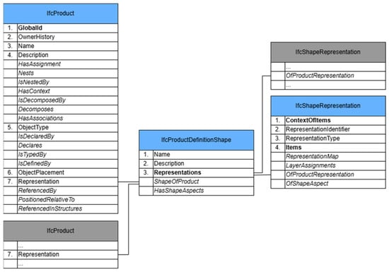
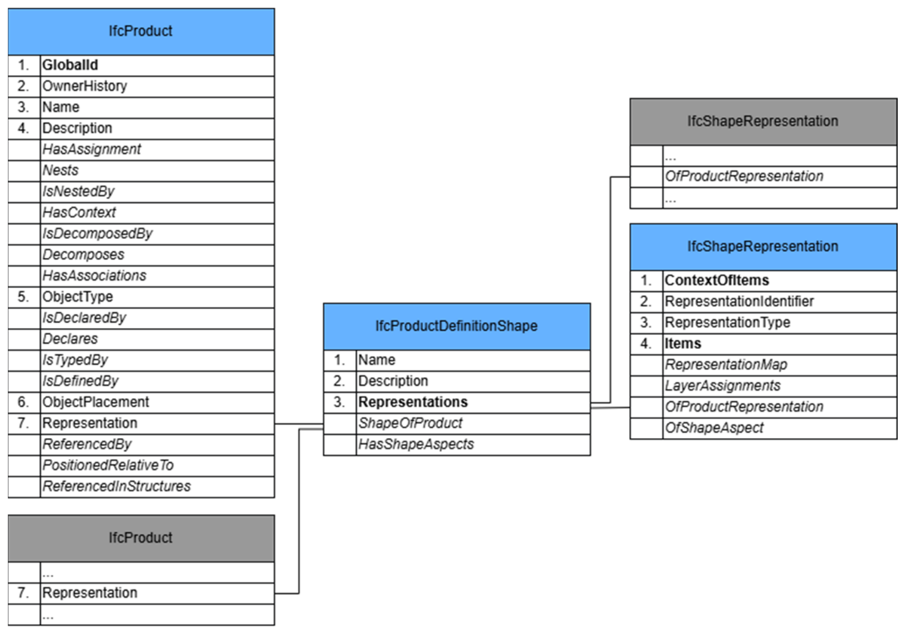
The geometric representation of entities belonging to the IfcProduct class is not mandatory. As shown in Figure 1, the seventh attribute, Representation, is optional and is associated with the IfcProductRepresentation class. IfcProductRepresentation is an abstract class that defines the representation of a product, including its geometric description. It has two subclasses, among which IfcProductDefinitionShape is particularly relevant for the scope of this study. This class specifies the shapes of an IfcProduct and allows multiple geometric representations of the same product, enabling an object to be described in different forms, such as three-dimensional solid geometry, two-dimensional annotations, or topological representations composed of vertices, edges, and faces.
Figure 1.
Schema illustrating IfcProductRepresentation and its relationships.
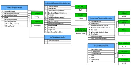
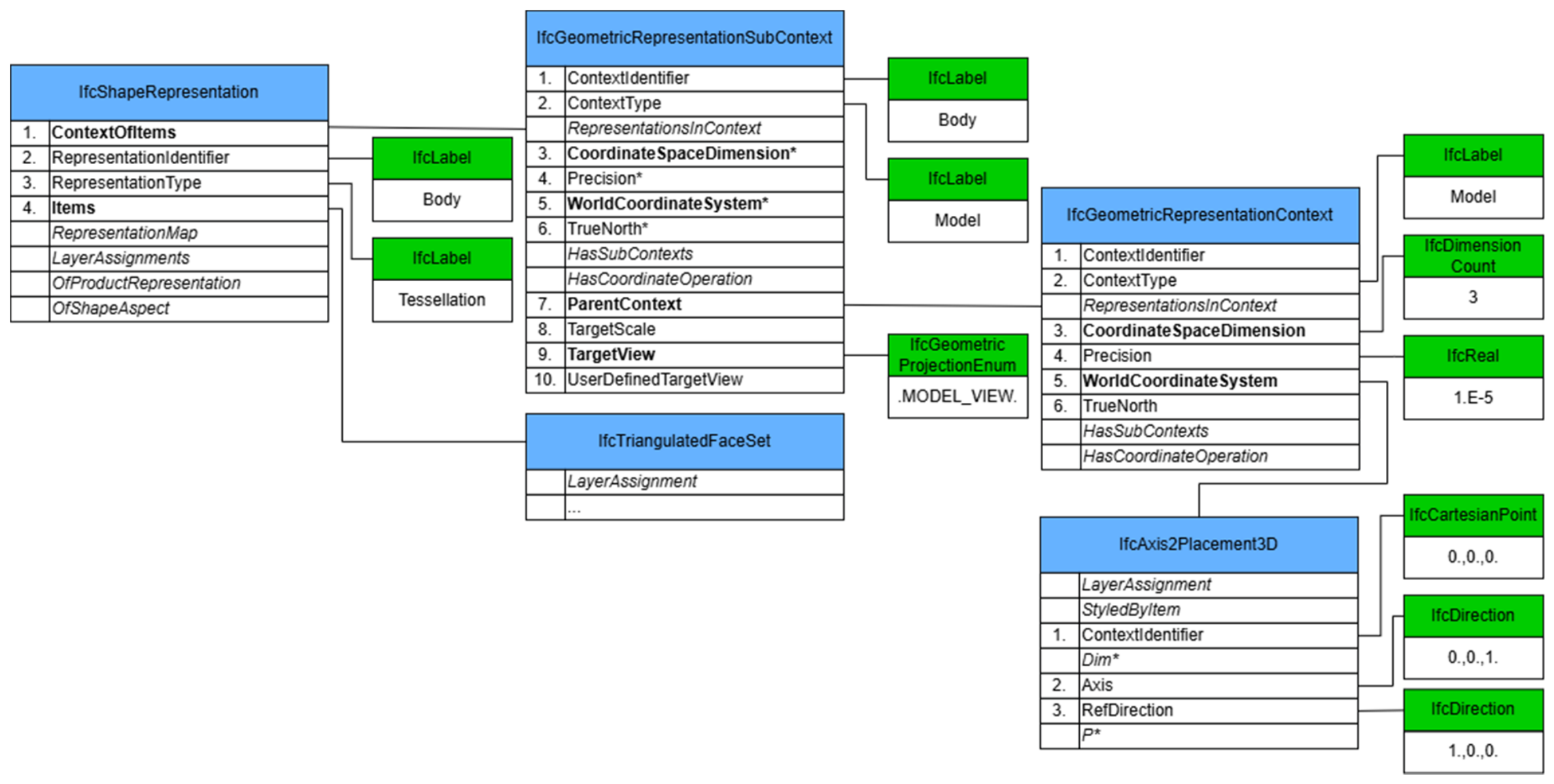
The IfcShapeRepresentation class represents a specific geometric representation of a product or a product component within a defined geometric representation context. This context is specified by the first attribute of the class. The geometric context itself is defined through the combination of IfcGeometricRepresentationContext and IfcGeometricRepresentationSubContext, which together provide the relevant information describing the environment and conditions in which the objects are represented, as shown in Figure 2. The RepresentationIdentifier attribute indicates a 3D Body representation as a surface or solid model. The RepresentationType indicates the type of shape, in this case a Tessellated one. With the Items attribute, we indicate the set of geometric representations that define that shape representation, and for the purpose of this work, it is related to an IfcTriangulatedFaceSet.
Figure 2.
Schema illustrating IfcShapeRepresentation and its relationships. Attributes marked with “*” are formally derived.
3.2.2. Representing Tessellated Geometry
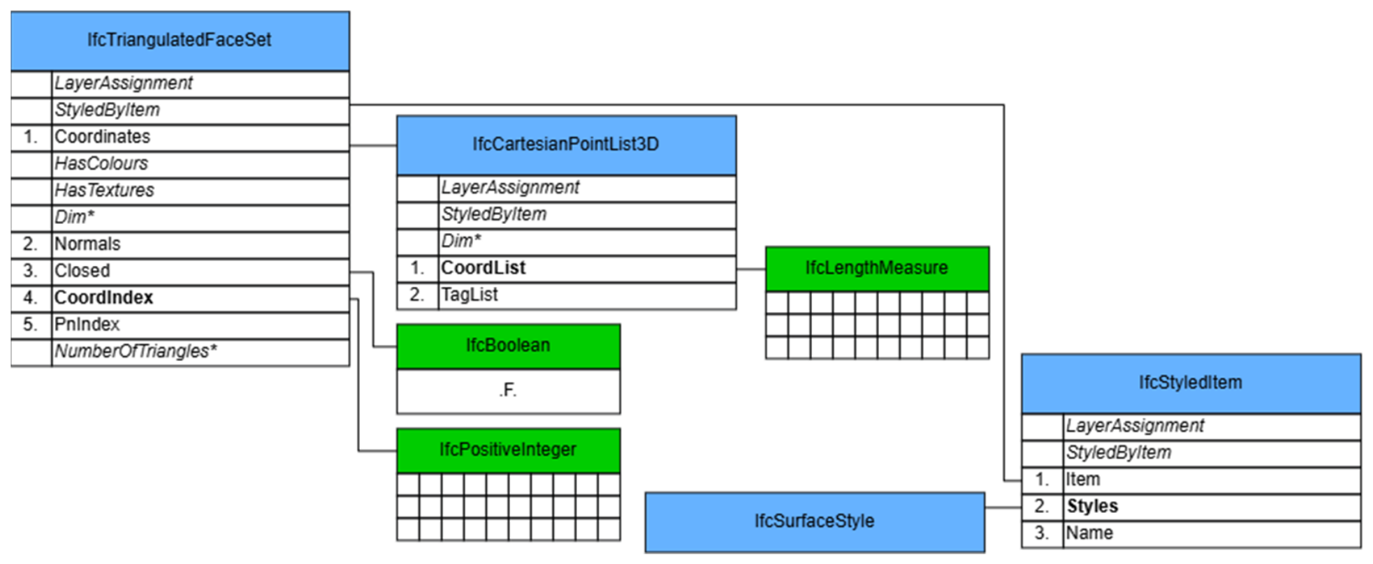
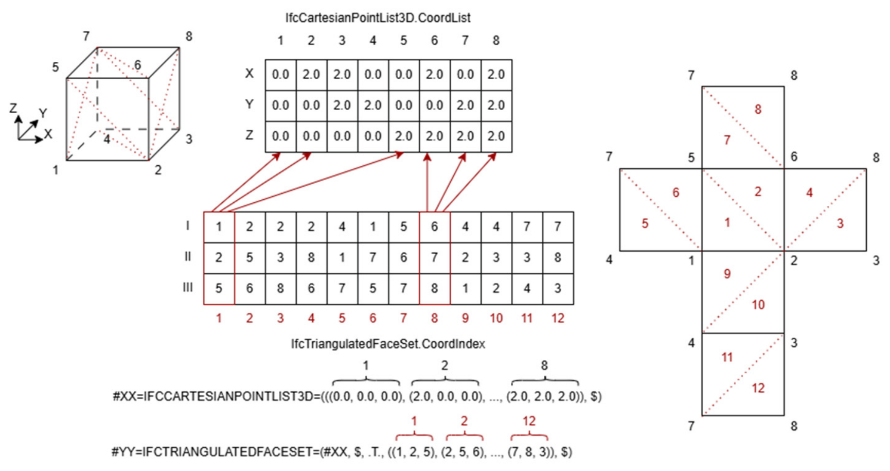
The IfcTriangulatedFaceSet is a tessellated face set in which all faces are bounded exclusively by triangles. Each triangular face is defined by an implicit polyline composed of three Cartesian points. The coordinates of these points are referenced through one-based indices into an ordered list of Cartesian points. These indices are stored in the two-dimensional list CoordIndex, where the first dimension corresponds to the list of triangular faces and the second dimension contains exactly three indices for each face. Each index refers to a Cartesian point defined in the IfcCartesianPointList3D entity, specifically within its CoordList attribute, thereby identifying the vertices of the triangle. Depending on the value of the inherited attribute Closed, an instance of IfcTriangulatedFaceSet represents a boundary representation (B-rep) when set to TRUE, or a face-based surface representation when set to FALSE. The representation of this class is shown in Figure 3.
Figure 3.
Schema illustrating IfcTriangulatedFaceSet and its relationships. Attributes marked with “*” are formally derived.
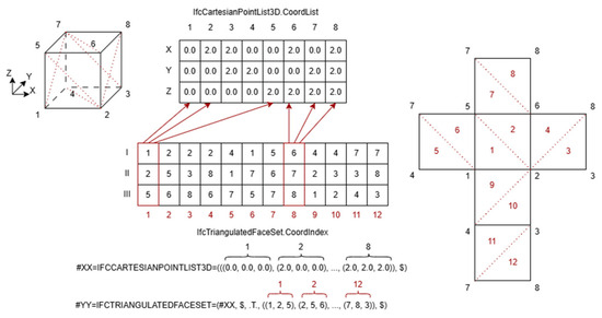
Figure 4 presents a cube as an illustrative example of how a tessellated mesh is represented using the IfcTriangulatedFaceSet class. A cube is adopted for clarity and readability; however, the principles described here are applicable to any three-dimensional object. Although the cube is inherently a three-dimensional entity, it is geometrically defined as an aggregation of two-dimensional triangular surfaces. For explanatory purposes, it can be conceptually unwrapped to make explicit the relationship between the triangular faces and their corresponding Cartesian points. In this context, the ordering of the three vertices defining each triangle is not particularly significant.
Figure 4.
Tessellated geometry represented using the IfcTriangulatedFaceSet class. Red indicates the triangles of the IfcTriangulatedFaceSet entity.
3.2.3. Mapping Textures to Tessellated Geometry
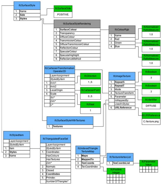
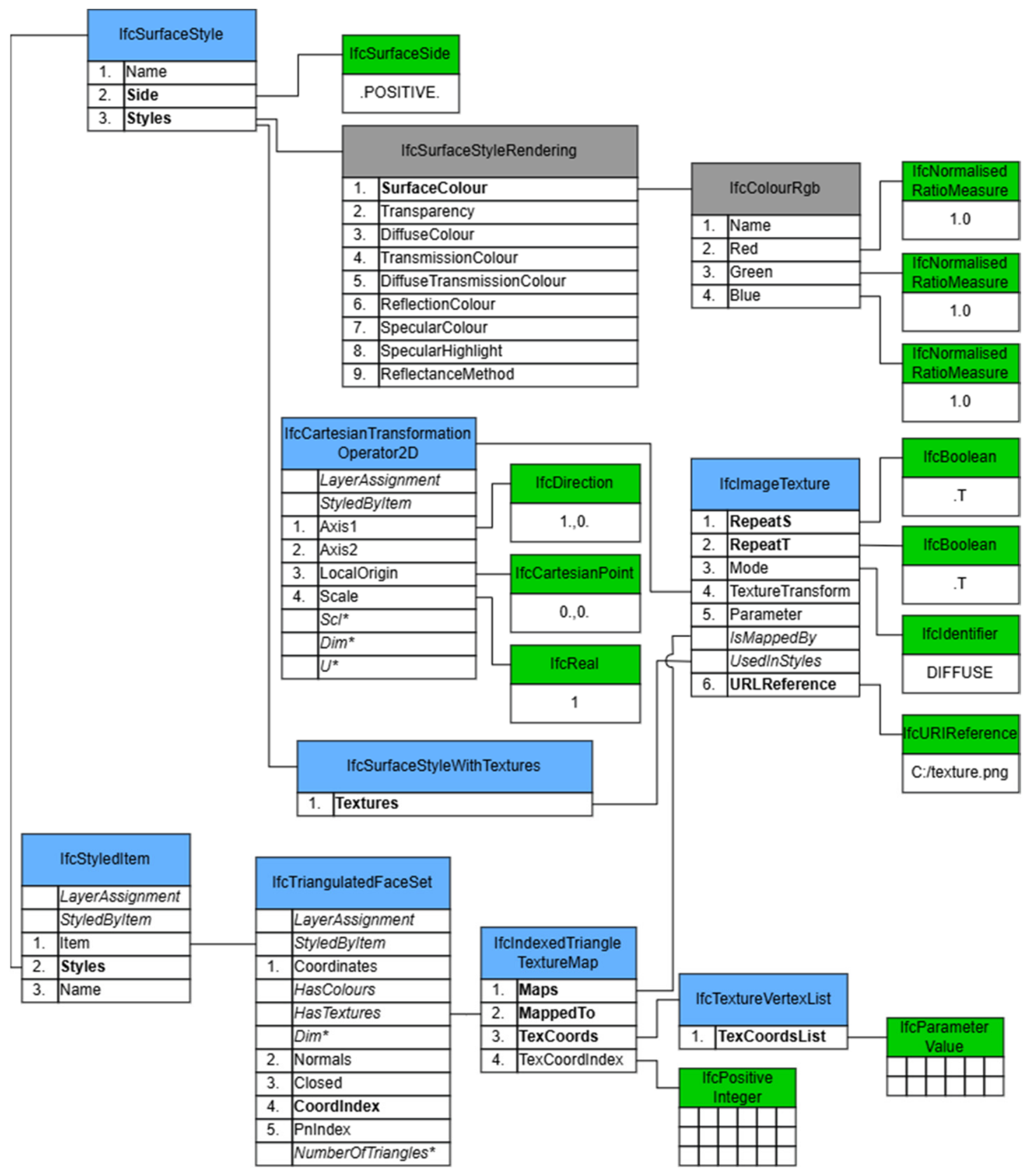
Up to this point, the discussion has focused on the geometric definition of objects composed of triangular meshes. The following section addresses the application of textures to such geometries. The IfcStyledItem class stores presentation style information by associating a geometric representation item with a style definition. In this context, it is linked to the IfcSurfaceStyle class, which defines the visual appearance of a surface. The Side attribute specifies the side of the surface to which the style is applied, while the Styles attribute provides a collection of surface style elements. As illustrated in Figure 5, the use of additional style definitions—such as IfcSurfaceStyleRendering—is not mandatory but can be beneficial to ensure an appropriate visual appearance when textures are not displayed. If a software application does not recognize textures, or if the visualization settings do not support textured views, and no alternative surface style is defined, a generic default material is typically applied. For this reason, assigning an additional rendering style can prevent fallback to a default appearance when texture visualization is unavailable. Texture application is achieved through the IfcSurfaceStyleWithTextures class, which enables the association of one or more textures (in the case of multitexturing) defined by IfcImageTexture entities. Each IfcImageTexture instance is linked, through the inverse attribute IsMappedBy, to an IfcIndexedTriangleTextureMap, which establishes the correspondence between texture coordinates and the surface geometry onto which the texture is mapped.
Figure 5.
Schema illustrating IfcTriangulateFaceSet and its relationships. Attributes marked with “*” are formally derived.
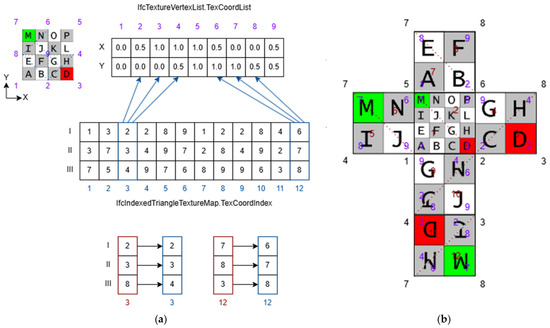
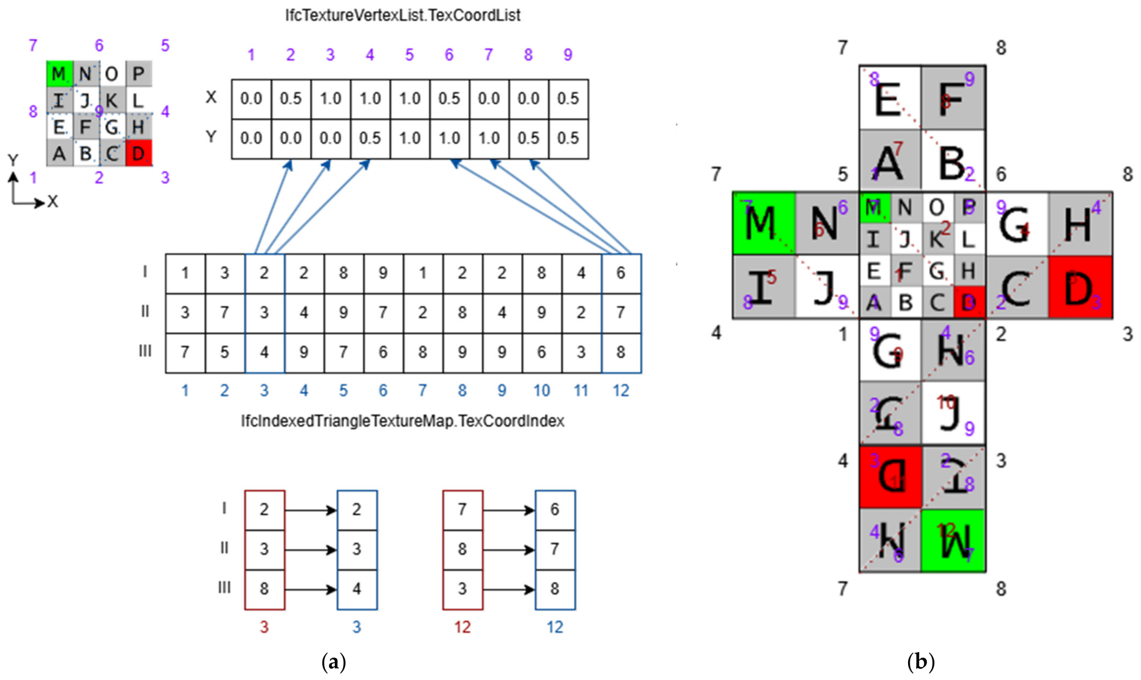
Within IfcIndexedTriangleTextureMap, the MappedTo attribute establishes a relationship with the IfcTriangulatedFaceSet class, which defines the triangular faces composing the product’s geometry. The TexCoords attribute refers to an IfcTextureVertexList, which specifies an ordered collection of texture vertices. As illustrated in Figure 6a, texture vertices are defined within a two-dimensional parametric space. Their coordinates are typically normalized within the [0, 1] interval to correspond precisely to the extents of the texture image, although values may exceed this range. When coordinate values exceed [0, 1], the behavior depends on the attributes RepeatS and RepeatT of IfcImageTexture. If these attributes are set to TRUE, the texture is repeated along the corresponding direction; if set to FALSE, the texture is applied only once, and the outermost row or column of pixels is stretched to fill the remaining area.
Figure 6.
(a) Relation between IfcIndexedTriangleTextureMap and IfcTextureVertexList. (b) Unwrapped texture cube. Red indicates the triangles of the IfcTriangulatedFaceSet entity, purple the corresponding vertices in the texture, and blue the triangles of the IfcIndexedTriangleTextureMap.
Following the same logic described in Figure 4, the attribute TexCoordIndex of IfcIndexedTriangleTextureMap defines triangular groupings based on the Cartesian point list stored in IfcTextureVertexList.TexCoordList. In this case, the ordering of the vertices within each triangle is significant, as each texture coordinate must correspond positionally to the respective vertex of the triangle defined in IfcTriangulatedFaceSet.CoordIndex. This positional correspondence determines the orientation of the texture on the surface and enables controlled rotation or alignment. Figure 6b illustrates different configurations for applying the same texture to a mesh, demonstrating how vertex ordering affects the final mapping.
3.2.4. Prototype Implementation
Once the IFC schema and the mechanisms for representing tessellated geometries and textures have been described in the previous sections, a prototype was implemented to enable the insertion of images as textures on planar geometries. Several approaches can be adopted to represent images within an IFC model, including applying textures directly to building elements such as walls, columns, or beams. In this work, images are instead represented using independent planar geometries to provide greater flexibility. In practice, images do not always correspond exactly to the dimensions of the associated building element, for example, because they may contain borders, legends, or other additional information. Using independent planar geometries avoids the need to stretch either the image or the building element and allows the user to position and scale the image more freely. Moreover, some images do not correspond directly to a specific building element, such as outputs from geotechnical analyses or multiple sections through structural elements. For these reasons, independent planar geometries were considered a more flexible and practical approach for incorporating structural analysis images into an IFC model.
The proposed add-on leverages the capabilities of Blender and provides several dedicated functionalities. The implementation and usage of the add-on are described step by step:
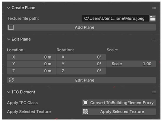
- Image selection. First, the user selects the path of the image to be applied as a texture. The Blender API provides ready-to-use graphical elements, such as file-selection buttons, whose underlying logic can be customized. In this case, the default file-selection interface is used to select the image from the user’s local file system, and the selected path is stored in a global variable for use in subsequent steps.
- Plane generation. Once the image path has been selected, the user presses the Add Plane button, which generates a plane with proportions corresponding to those of the selected image. This operation adds a geometrical mesh representing the plane to the Blender scene.
- Plane positioning and transformation. Because the dimensions of an image typically do not match those of the target object, the user can subsequently adjust the plane’s position, rotation, and scale using the standard Blender editing tools. The values entered by the user for these transformations are stored in global variables. When the user presses the Edit Plane button, these values are retrieved and applied to the mesh through the Blender API.
- IFC conversion and texture mapping. The final step involves pressing the Convert IfcBuildingElementProxy button. IfcBuildingElementProxy is used as a generic IFC class suitable for representing the planar geometry in the proposed workflow. If a more specific IFC class is required, the user can modify the assigned class directly within Blender. The conversion operation transforms the plane into an IfcBuildingElementProxy and prepares its representation for texture mapping. Using the Bonsai API, the IFC conversion can be performed with a single line of code. However, the converted plane is initially assigned an IfcPolygonalFaceSet representation. When the user presses the Apply Selected Texture button, this representation is replaced with the tessellated and texture-mapped representation described in the preceding methodology. The new representation is generated using the IfcOpenShell API.
4. Results
To illustrate the add-on shown in Figure 7 in a structural engineering scenario, the workflow was applied to the output of a nonlinear static (pushover) analysis. This type of analysis is used to assess the seismic performance of a structure and, among its outputs, returns the distribution of principal tensile stresses over an entire load-bearing wall, which identifies the regions most exposed to cracking under seismic demand. Because this result is inherently spatial, its meaning depends on where each value occurs on the structure: carrying it within the IFC model, rather than leaving it in a separate report, keeps the analytical output registered to the geometry it refers to, so that the critical regions can be read directly on the element.
Figure 7.
User interface of the Blender add-on.
The resulting IFC model can correctly represent the image as a texture applied to the planar geometry. Although this texture visualization is currently not supported directly within Bonsai, the texture is correctly visualized on the plane once the IFC file is saved and opened in a compatible IFC viewer, as shown in Figure 8.
The resulting IFC model was successfully opened by external viewers such as KITModelViewer 7.5 and was also validated using the IFC Validation Service [45]. The model successfully passed the STEP Syntax, IFC Schema, and Normative IFC Rules tests, confirming its compliance with the corresponding IFC validation requirements.
Figure 8.
Texture correctly applied and visualized in KitModelViewer [46].
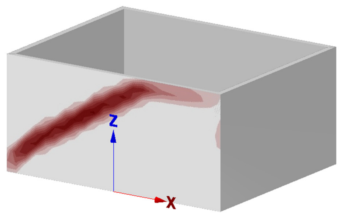
The procedure can be completed within a matter of seconds, with the overall duration primarily depending on the time required by the user to locate, rotate, and scale the plane to the desired position. The resulting file size does not increase significantly because the image data themselves are not embedded within the IFC file. Instead, the IFC file contains the texture-mapping information together with an IfcImageTexture. URLReference points to the external image resource. Consequently, exchanging the IFC file alone does not guarantee preservation of the texture visualization: the referenced image resource must remain available and accessible to the receiving application.
The main practical limitation observed in the tested software ecosystem is the uneven implementation of IFC texture visualization across viewers. This should not be interpreted as a limitation of the IFC schema itself, which defines the relevant entities and relationships for texture representation and mapping. Rather, individual applications implement different subsets of IFC functionality according to their supported exchange requirements and MVDs. Table 1 therefore reports the implementation support observed in the viewers tested in this study. Among the viewers tested, only KitModelViewer was found to support texture rendering; however, it is limited to local image files and does not support web-hosted images.
Table 1.
List of viewers supporting texture visualization.
A further limitation of this work is that the texture is applied to a plane rather than directly to the object itself. This design choice stems from the need to store the texture-mapping information and the image reference within specific IFC that can be easily hidden within the viewer. As future work, however, the add-on could be extended to support the direct application of textures to other building elements, such as walls and floors.
Beyond this specific case, the same mechanism is agnostic to the origin of the image: any spatially distributed visual structural output can be associated with the model as an externally referenced texture using the same mechanism. The demonstrated case is therefore representative of this broader category rather than a special instance. Compared with tabular or purely semantic encodings, keeping the result as an image on the model preserves its spatial correspondence with the geometry, so that where a phenomenon occurs is read directly on the element rather than reconstructed from separate data.
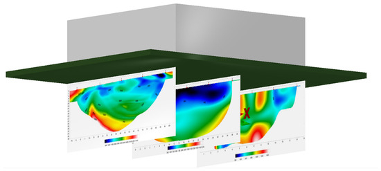
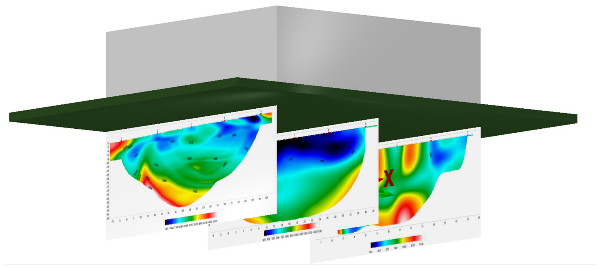
The current framework is applicable not only to structural safety assessments but also to other domains, such as geotechnical analysis, as demonstrated in Figure 9.
Figure 9.
Texture correctly applied to three planes representing tomographic sections beneath a building and visualized in KITModelViewer [46].
5. Discussion
The proposed prototype directly addresses the informational discontinuity highlighted at the outset, whereby the outputs of structural analyses often remain confined to external documents or software, breaking the flow of information among designers, structural engineers, inspectors, and clients. The texture mapping and the reference to the associated image resource are encoded using the vendor-neutral IFC schema and are therefore independent of the authoring application that generated them. However, correct visualization in a receiving application still depends on whether that application implements the relevant IFC texture functionality and can access the referenced image resource. By encoding the texture mapping and the reference to the associated image resource within the IFC model, the analytical or experimental result can be kept spatially registered to the geometry to which it refers. The IFC representation is vendor-neutral and independent of the authoring application; however, the image data remain an external resource, and correct visualization in a receiving application depends both on the implementation of the relevant IFC texture functionality and on the continued accessibility of the referenced image. Unlike an external report or a linked document, which records that a result exists without specifying where on the element it applies, keeping the result as a texture on the geometry preserves its spatial correspondence with the specific surface it refers to. In this sense, the prototype is intended to restore, at least for the visual component, the informational continuity that BIM promises but that in the structural domain often remains unfulfilled. The extent to which this improves communication and interpretation among stakeholders is a potential benefit that has not been experimentally evaluated in this work.
Several recent studies have explored the generation of textures from point clouds and images in the context of BIM. In [23], a method for deriving textures from a BIM model in combination with point clouds and images is clearly presented; however, the authors do not apply these textures directly to the BIM model, instead overlaying them within a 3D view inside Revit. Combining such a texture-generation approach with a framework like the one proposed in this work could represent a significant step forward. Similarly, [24] adopts a different strategy to obtain textures from point clouds, but likewise does not apply the resulting textures directly to the BIM model, identifying this integration as a direction for future work. In a related but distinct application, [25] employs point clouds not for texture generation but for reconstructing the geometries of bridges, beams, and other building components, together with their associated damage, as tessellated IFC geometries; an approach of this kind could similarly be combined with the framework proposed here to associate textures with such highly detailed and precise geometries. Beyond geometry and texture generation, other studies [26] focus on the semantic enrichment of geometries derived from images and point clouds, which could prove particularly valuable for structural safety assessment and HBIM applications, while a separate line of research [12] investigates the use of deep learning for inspection and for the integration of structural and safety-related data. Taken together, these works indicate substantial interest in generating detailed geometries and textures from scans and point clouds; however, a clear gap remains in linking these two outputs directly within the IFC model, with this task currently delegated to proprietary ecosystems or alternative formats. The gap, therefore, lies not so much in the generation of textures as in their standard-compliant anchoring: it is precisely this aspect that the present work addresses. Addressing this gap could yield meaningful advancements in both the HBIM and structural safety domains.
A separate strand of the literature addresses texture representation without relying on IFC as the carrier format. For instance, Hernández et al. [34] proposes a multi-layer Augmented Reality architecture that relies on IFC data repositories in combination with PLY extensions for images, textures, and point clouds. Other efforts targeting Virtual Reality applications [32] use IFC only as the base geometric model, applying textures in a separate environment and visualizing the result in Unity through a COLLADA file. Similarly, the cultural heritage application proposed in [35] treats the IFC model and a separate 3D geometric model (OBJ) as distinct entities in order to display textures, rather than representing the texture association directly through IFC entities and mappings. In all these cases, IFC is relegated to the role of a geometric container, while the visual information resides elsewhere, in a separate environment or format. The approach proposed here stands in contrast to this choice: rather than pairing the standard with a second model, it keeps the texture mapping and the reference to the image resource within the IFC file, while the image data themselves remain external, avoiding the duplication of models and the dependence on formats that once again break the informational continuity that openBIM is meant to guarantee.
Within the more limited body of work that does address texture representation directly in IFC, [36] briefly discusses the relationships between the relevant IFC elements, though without sufficient detail and without demonstrating the application of texture to any object. Earlier work by [37] shows a texture applied to wall damage using XbimXplorer [38], but likewise does not explain in detail how this is implemented. References [39,40], meanwhile, provide a highly accurate description of the class relationships involved in applying texture to objects, yet without detailing how these relationships should be properly encoded, leaving readers to infer the implementation from the IFC specification itself. Finally, [13] generates geometries in Blender and applies textures to them, using texture to represent damage; however, this framework stops short of translating the result into IFC, which is precisely the missing step that the approach proposed in this work aims to address using a similar underlying logic. With respect to this body of work, the contribution proposed here is twofold. On the implementation side, it provides the complete, operational account of the encoding that this literature leaves unstated—bridging the distance between the description of the class relationships [36,39,40] and their actual application to an object, and carrying into IFC the step that [13,37] do not complete. On the conceptual side, and more substantially, it employs the texture mechanism not for visual rendering or the documentation of the as-is condition—the use made of it by nearly all of these works—but as a carrier of an analytical or experimental result, kept registered to the geometry of the element it refers to and transferable within the model through standard openBIM exchange. It is in this second respect that the work distinguishes itself from existing approaches.
This does not eliminate the problem but shifts its center. If encoding the texture mapping and the associated external image reference within the IFC model is possible and standard-compliant, the critical point moves to the reading stage: correct visualization depends on the support offered by viewers which, as shown in the results, remains largely lacking.
The development of these tools has been made possible primarily through the availability of open source software that supports professional and research activities by providing APIs for building custom tools. In this sense, the role of research can be to develop and share free, open-source tools based on open standards, thereby enhancing interoperability, disseminating best practices, and advancing the AEC research field. The fact that, among the several IFC viewers considered, only one supports texture visualization is a significant indicator of why this form of representation remains uncommon and not widely adopted. There is a shortage of tools for both writing and reading IFC-based texture representations. Moreover, the reliance of several researchers on other, non-standardized formats [32,34,35] hinders interoperability, multiplying the effort required to convert and maintain data across multiple formats and increasing the risk of information loss during translation between them. Rather than expending time and effort on custom, ad hoc solutions, it is preferable to focus on developing and sharing open source tools compliant with existing standards, as is being done by the IfcOpenShell development team with Bonsai, which is planned to support the reading and writing of texture representations in the future. This work proposes a simple prototype illustrating how the IFC standard handles texture representation, with the aim of sharing knowledge and fostering the development of further tools.
6. Conclusions
This work stems from the observation that a growing share of the information relevant to interpreting structural behavior is inherently visual in nature and that, in many cases, the image is the only practical means of conveying an analytical or experimental result, despite the lack of established guidance on how to integrate it systematically within IFC models. Building on this premise, the study examined how the IFC standard supports the visualization of textures applied to geometric entities, clarifying the classes involved and their relationships, and developed a prototype within the Bonsai environment, based on Blender, capable of generating planar geometries in 3D space and applying image-based textures to them, thereby associating visual information with IFC geometry through standard texture-mapping entities and an external image reference. A key contribution of this work is the provision of a detailed and accessible description of how IFC for texture representation can be correctly related and implemented in a reproducible manner. Although the mechanisms are defined within the IFC standard, their practical application remains insufficiently documented and is not fully supported by current high-level libraries. The proposed approach therefore contributes to bridging the gap between the theoretical capabilities of the IFC standard and their practical implementation, providing a clearer basis for developers and practitioners to adopt and reproduce this functionality. The approach was demonstrated through a case study dedicated to the visualization of structural testing results.
The main findings of this work can be summarized as follows:
- The paper provides a complete, operational account of how to correctly implement and manage textures within an IFC model, clarifying the classes involved and their relationships and filling a gap left only partially addressed in the literature.
- It employs the texture mechanism not as mere visual rendering but as a carrier of an analytical or experimental result kept anchored to the geometry of the element it refers to.
- The case study shows that such integration is technically feasible and standard-compliant.
- The main critical point has shifted from writing to reading the data, since the support offered by current viewers for texture visualization remains largely lacking.
Several directions for future work emerge from the limitations discussed above. First, there is a need for a viewer capable of supporting not only locally stored images but also web-hosted images, thereby overcoming one of the main barriers to the wider adoption of this representation. Second, if the output images are structured according to a triangulated arrangement, it may be possible to develop procedures for applying textures directly to 3D meshes, including curved and geometrically complex surfaces; this direction would be particularly relevant from an HBIM (Historic Building Information Modelling) perspective, where the accurate representation of surface details is often critical. Finally, future work should address the implementation of multitexture support to enable multiple simultaneous analyses of the same object, a need that has already been highlighted in previous research [36].
Author Contributions
Conceptualization, D.A., G.M. and C.Z.; methodology, D.A. and C.Z.; software, D.A.; validation, D.A. and G.M.; writing—original draft preparation, D.A. and G.M.; writing—review and editing, D.A., G.M. and G.D.C.; visualization, D.A.; supervision, G.D.C. and C.Z.; project administration, G.D.C. and C.Z.; funding acquisition, C.Z. All authors have read and agreed to the published version of the manuscript.
Funding
This research received no external funding.
Data Availability Statement
The original data presented in the study are openly available in Github at https://github.com/Daavogaro/IFC-Texture (assessed on 20 July 2026).
Acknowledgments
During the preparation of this manuscript/study, the authors used ChatGPT-4 and DeepL Translator for the purposes of translation and grammar and spelling checks. The authors have reviewed and edited the output and take full responsibility for the content of this publication.
Conflicts of Interest
The authors declare no conflicts of interest.
Abbreviations
The following abbreviations are used in this manuscript:
| AEC | Architectural, engineering and construction |
| BIM | Building information modeling |
| COLLADA | Collaborative design activity |
| FEM | Finite element method |
| HBIM | Historical BIM |
| IFC | Industry foundation classes |
| O&M | Operation and maintenance |
| PLY | Polygon file format |
| VR | Virtual reality |
References
- Borrmann, A.; Beetz, J.; Koch, C.; Liebich, T.; Muhic, S. Industry Foundation Classes: A Standardized Data Model for the Vendor-Neutral Exchange of Digital Building Models. In Building Information Modeling; Borrmann, A., König, M., Koch, C., Beetz, J., Eds.; Springer International Publishing: Cham, Switzerland, 2018; pp. 81–126. [Google Scholar]
- Gomes, A.M.; Azevedo, G.; Sampaio, A.Z.; Lite, A.S. BIM in Structural Project: Interoperability Analyses and Data Management. Appl. Sci. 2022, 12, 8814. [Google Scholar] [CrossRef] [Scilit]
- Ciccone, A.; Ciotta, V.; Asprone, D. Integration of Structural Information within a Bim-Based Environment for Seismic Structural e-Permits. J. Civ. Eng. Manag. 2023, 29, 171–193. [Google Scholar] [CrossRef] [Scilit]
- Raitviir, C.-R.; Lill, I. Conceptual Framework of Information Flow Synchronization Throughout the Building Lifecycle. Buildings 2024, 14, 2207. [Google Scholar] [CrossRef] [Scilit]
- Ji, X.; Miao, Z.; Kromanis, R. Vision-Based Measurements of Deformations and Cracks for RC Structure Tests. Eng. Struct. 2020, 212, 110508. [Google Scholar] [CrossRef] [Scilit]
- Mousa, M.A.; Yussof, M.M.; Hussein, T.S.; Assi, L.N.; Ghahari, S. A Digital Image Correlation Technique for Laboratory Structural Tests and Applications: A Systematic Literature Review. Sensors 2023, 23, 9362. [Google Scholar] [CrossRef] [Scilit] [PubMed]
- Liu, Y.; Yeoh, J.K.W. Automated Crack Pattern Recognition from Images for Condition Assessment of Concrete Structures. Autom. Constr. 2021, 128, 103765. [Google Scholar] [CrossRef] [Scilit]
- Jadhav, Y.; Berthel, J.; Hu, C.; Panat, R.; Beuth, J.; Barati Farimani, A. StressD: 2D Stress Estimation Using Denoising Diffusion Model. Comput. Methods Appl. Mech. Eng. 2023, 416, 116343. [Google Scholar] [CrossRef] [Scilit]
- Feroz, S.; Abu Dabous, S. UAV-Based Remote Sensing Applications for Bridge Condition Assessment. Remote Sens. 2021, 13, 1809. [Google Scholar] [CrossRef] [Scilit]
- Omar, T.; Nehdi, M.L. Remote Sensing of Concrete Bridge Decks Using Unmanned Aerial Vehicle Infrared Thermography. Autom. Constr. 2017, 83, 360–371. [Google Scholar] [CrossRef] [Scilit]
- Wang, H.-W.; Hu, Z.-Z.; Lin, J.-R. Bibliometric Review of Visual Computing in the Construction Industry. Vis. Comput. Ind. Biomed. Art 2020, 3, 14. [Google Scholar] [CrossRef] [Scilit] [PubMed]
- Hattori, K.; Oki, K.; Sugita, A.; Sugiyama, T.; Chun, P. Deep Learning-Based Corrosion Inspection of Long-Span Bridges with BIM Integration. Heliyon 2024, 10, e35308. [Google Scholar] [CrossRef] [Scilit] [PubMed]
- Levine, N.M.; Narazaki, Y.; Spencer, B.F. Development of a Building Information Model-Guided Post-Earthquake Building Inspection Framework Using 3D Synthetic Environments. Earthq. Eng. Eng. Vib. 2023, 22, 279–307. [Google Scholar] [CrossRef] [Scilit]
- Karluklu, D.; Rinaldi, C.; Crognale, M.; Figuli, L.; Gattulli, V. Enhanced Image Processing and Storage for Defect Evaluation in BIM of Inspected Steel Bridges. Discov. Civ. Eng. 2025, 2, 11. [Google Scholar] [CrossRef] [Scilit]
- Otranto, R.B.; Miceli Junior, G.; Pellanda, P.C. BIM-FM Integration through openBIM: Solutions for Interoperability towards Efficient Operations. J. Inf. Technol. Constr. 2025, 30, 298–318. [Google Scholar] [CrossRef] [Scilit]
- buildingSMART. Industry Foundation Classes (IFC). Available online: https://www.buildingsmart.org/standards/bsi-standards/industry-foundation-classes/ (accessed on 12 June 2026).
- Laakso, M.; Kiviniemi, A. The IFC Standard-A Review of History, Development, and Standardization. J. Inf. Technol. Constr. 2012, 17, 134–161. [Google Scholar]
- Yu, Y.; Kim, S.; Jeon, H.; Koo, B. A Systematic Review of the Trends and Advances in IFC Schema Extensions for BIM Interoperability. Appl. Sci. 2023, 13, 12560. [Google Scholar] [CrossRef] [Scilit]
- Kone, V.; Mahesh, G. An Ontology-Driven Bi-Directional Workflow for Integrating Project Management Data into the IFC Standard. J. Inf. Technol. Constr. 2025, 30, 1768. [Google Scholar] [CrossRef] [Scilit]
- Ait-Lamallam, S.; Yaagoubi, R.; Sebari, I.; Doukari, O. Extending the IFC Standard to Enable Road Operation and Maintenance Management through OpenBIM. ISPRS Int. J. Geo-Inf. 2021, 10, 496. [Google Scholar] [CrossRef] [Scilit]
- Kang, D.; Kim, J.; Lee, J.; Lee, H.; Kim, J.; Byun, J. A Study on Vector-Based Processing and Texture Application Techniques for 3D Object Creation and Visualization. Appl. Sci. 2025, 15, 4011. [Google Scholar] [CrossRef] [Scilit]
- Rohil, M.K.; Agarwal, Y. Texture Mapping and Surface Models for Augmented Reality Applications. In Proceedings of the 2026 IEEE International Conference for Convergence in Computing Technology (I3CTCON), Lonavala, India, 14–15 March 2026; pp. 1–9. [Google Scholar]
- Alshawabkeh, Y.; Baik, A.; Fallatah, A. As-Textured As-Built BIM Using Sensor Fusion, Zee Ain Historical Village as a Case Study. Remote Sens. 2021, 13, 5135. [Google Scholar] [CrossRef] [Scilit]
- Andriasyan, M.; Moyano, J.; Nieto-Julián, J.E.; Antón, D. From Point Cloud Data to Building Information Modelling: An Automatic Parametric Workflow for Heritage. Remote Sens. 2020, 12, 1094. [Google Scholar] [CrossRef] [Scilit]
- Isailović, D.; Stojanovic, V.; Trapp, M.; Richter, R.; Hajdin, R.; Döllner, J. Bridge Damage: Detection, IFC-Based Semantic Enrichment and Visualization. Autom. Constr. 2020, 112, 103088. [Google Scholar] [CrossRef] [Scilit]
- Shu, J.; Zhang, C.; Yu, K.; Shooshtarian, M.; Liang, P. IFC-Based Semantic Modeling of Damaged RC Beams Using 3D Point Clouds. Struct. Concr. 2023, 24, 389–410. [Google Scholar] [CrossRef] [Scilit]
- Lai, H.; Deng, X. Interoperability Analysis of Ifc-Based Data Exchange between Heterogeneous Bim Software. J. Civ. Eng. Manag. 2018, 24, 537–555. [Google Scholar] [CrossRef] [Scilit]
- Noardo, F.; Krijnen, T.; Arroyo Ohori, K.; Biljecki, F.; Ellul, C.; Harrie, L.; Eriksson, H.; Polia, L.; Salheb, N.; Tauscher, H.; et al. Reference Study of IFC Software Support: The GeoBIM Benchmark 2019—Part I. Trans. GIS 2021, 25, 805–841. [Google Scholar] [CrossRef] [Scilit]
- Du, S.; Hou, L.; Zhang, G.; Tan, Y.; Mao, P. BIM and IFC Data Readiness for AI Integration in the Construction Industry: A Review Approach. Buildings 2024, 14, 3305. [Google Scholar] [CrossRef] [Scilit]
- Yeh, Y.-Y.; Huang, J.-B.; Kim, C.; Xiao, L.; Nguyen-Phuoc, T.; Khan, N.; Zhang, C.; Chandraker, M.; Marshall, C.S.; Dong, Z.; et al. Texturedreamer: Image-Guided Texture Synthesis through Geometry-Aware Diffusion. In Proceedings of the 2024 IEEE/CVF Conference on Computer Vision and Pattern Recognition (CVPR), Seattle, WA, USA, 16–22 June 2024; pp. 4304–4314. [Google Scholar]
- Duque Mahecha, S.; Aguacil Moreno, S.; Dennis Stoll, A.; Deschamps, L.; De Sousa Pereira, T. Texture Mapping and IFC Material Retrievement for Virtual Reality Applications. In Proceedings of the 17th IBPSA Conference, Bruges, Belgium, 1–3 September 2021; Saelens, D., Laverge, J., Boydens, W., Helsen, L., Eds.; EPFL: Lausanne, Switzerland, 2021. [Google Scholar]
- Aguacil Moreno, S.; Duque Mahecha, S.; Stoll, A.D.; De Sousa Pereira, S.; Deschamps, L.; Bacher, J.-P. Virtual Reality Enabled Building-Data Management through the Combination of a Fully Integrated IFC-BIM Model and an IoT-Based Building Management System. In Proceedings of the 17th IBPSA Conference, Bruges, Belgium, 1–3 September 2021; EPFL: Lausanne, Switzerland, 2021; Volume 1, pp. 3262–3267. [Google Scholar]
- IfcOpenShell v0.8.3. IfcOpenShell. Available online: https://ifcopenshell.org/ (accessed on 23 July 2026).
- Hernández, J.L.; Martín Lerones, P.; Bonsma, P.; Van Delft, A.; Deighton, R.; Braun, J.-D. An IFC Interoperability Framework for Self-Inspection Process in Buildings. Buildings 2018, 8, 32. [Google Scholar] [CrossRef] [Scilit]
- Farella, E.M.; Rigon, S.; Remondino, F.; Stan, A.; Ioannidis, G.; Münster, S.; Medici, M.; Maietti, F.; Sánchez, A. Methods, Data and Tools for Facilitating a 3d Cultural Heritage Space. Int. Arch. Photogramm. Remote Sens. Spat. Inf. Sci. 2024, 48, 197–204. [Google Scholar] [CrossRef] [Scilit]
- Artus, M.; Alabassy, M.S.H.; Koch, C. A BIM Based Framework for Damage Segmentation, Modeling, and Visualization Using IFC. Appl. Sci. 2022, 12, 2772. [Google Scholar] [CrossRef] [Scilit]
- Artus, M.; Alabassy, M.; Koch, C. IFC Based Framework for Generating, Modeling and Visualizing Spalling Defect Geometries; Universitätsverlag der TU Berlin: Berlin, Germany, 2021; pp. 176–186. [Google Scholar]
- Lockley, S.; Benghi, C.; Černý, M. Xbim. Essentials: A Library for Interoperable Building Information Applications. J. Open Source Softw. 2017, 2, 473. [Google Scholar] [CrossRef] [Scilit]
- Zhang, J.; Yu, F.; Li, D.; Hu, Z. Development and Implementation of an Industry Foundation Classes-based Graphic Information Model for Virtual Construction. Comput.-Aided Civ. Infrastruct. Eng. 2014, 29, 60–74. [Google Scholar] [CrossRef] [Scilit]
- Zhang, J.; Yu, F.; Wu, D. IFC and OpenGL-Based Representation and Development of 3D Realistic Model in Virtual Construction. In Proceedings of the International Conference on Computing in Civil and Building Engineering (ICCCBE 2010), Nottingham, UK, 30 June–2 July 2010; Nottingham University Press: Nottingham, UK, 2010. [Google Scholar]
- Lee, W.; Jeong, Y.; Jeong, W.; Yu, Y.; Park, S.I.; Koo, B. An IFC-Based Framework for Automated Integration of Structural Analysis Results to Support BIM-Based Code Compliance. Buildings 2026, 16, 746. [Google Scholar] [CrossRef] [Scilit]
- Blender v4.5. Foundation Blender. Available online: https://www.blender.org/ (accessed on 18 September 2025).
- IfcOpenShell. Bonsai v0.8.3. Available online: https://bonsaibim.org/index.html (accessed on 18 September 2025).
- buildingSMART. Technical IFC 4.3 ADD2. Available online: https://standards.buildingsmart.org/IFC/RELEASE/IFC4_3/ (accessed on 28 October 2025).
- buildingSMART. Technical IFC Validation Service. Available online: https://www.buildingsmart.org/users/services/validation-service/ (accessed on 20 July 2026).
- Karlsruhe Institute of Technology KITModelViewer v7.5 (Build 3636). Available online: https://www.iai.kit.edu/english/4561.php (accessed on 20 July 2026).
- BIMvision v3.1.4. Available online: https://bimvision.eu/download/ (accessed on 18 September 2025).
- That Open That Open Company v3.1.0. Available online: https://github.com/ThatOpen/ (accessed on 20 July 2026).
- IfcOpenShell. Bonsai Viewer v0.8.6. Available online: https://s3.amazonaws.com/ifcopenshell-builds/BonsaiViewer-v0.8.6-d3b12d0-win64.zip (accessed on 20 July 2026).
- Flinker GmbH Flinker v3.2.2. Available online: https://flinker.app/ (accessed on 20 July 2026).

Disclaimer/Publisher’s Note: The statements, opinions and data contained in all publications are solely those of the individual author(s) and contributor(s) and not of MDPI and/or the editor(s). MDPI and/or the editor(s) disclaim responsibility for any injury to people or property resulting from any ideas, methods, instructions or products referred to in the content. |
© 2026 by the authors. Licensee MDPI, Basel, Switzerland. This article is an open access article distributed under the terms and conditions of the Creative Commons Attribution (CC BY) license.