


Abstract
Foliated metamorphic rock exists widely in the surrounding rock of tunnel structures, underground utility caverns and mountain civil structures, and its laminated foliation structure induces obvious anisotropic time-dependent creep deformation, which seriously threatens the long-term service safety of underground building support systems. The strength and time-dependent deformation of foliated phyllite vary sharply with bedding dip angles, and long-term creep easily triggers large convergence, secondary-lining cracking and structural intrusion failure of tunnel structures. In this work, multi-stage uniaxial compression creep tests were carried out on sericite phyllite specimens with foliation dip angles of 0°, 30°, 45° and 90° using a programmable rock creep testing apparatus, aiming to investigate the anisotropic creep behaviors of phyllite surrounding rock for tunnel engineering. The anisotropic P-wave velocity characteristics of phyllite under different bedding angles were first analyzed to quantify the directional structural difference in the rock matrix. Based on the creep test curves, the full-stage deformation laws including instantaneous strain, decelerating creep, steady-state creep and accelerating creep were systematically summarized for specimens with different bedding orientations. Combined with macroscopic creep failure modes, phenomenological analysis was performed on the anisotropic creep damage behavior controlled by foliation weak planes. The results demonstrate that inclined bedding phyllite presents the most severe creep deformation and steady-state creep rate, and three typical creep failure modes (cross-bedding shear failure, tensile splitting failure, bedding slip shear failure) correspond to horizontal, vertical and inclined foliation specimens respectively. This study quantitatively reveals the time-dependent anisotropic mechanical properties of foliated soft rock, establishes a systematic experimental database and provides experimental basis for long-term stability prediction, and enriches the rheological research system for the durability evaluation of underground civil structures.
1. Introduction
Foliated metamorphic rocks including phyllite, slate and schist occur widely as surrounding rock for mountain highway tunnels, underground hydropower caverns and buried municipal underground structures. Typical phyllite shows prominent transversely isotropic mechanical behavior controlled by dense-schistosity weak planes. Its mechanical properties are relatively uniform parallel to bedding but considerably weaker across bedding; the schistosity dip angle governs anisotropy in strength, instantaneous deformation and time-dependent creep damage, leading to long-term performance deterioration in tunnel structures [1]. Bedding-plane orientation strongly controls excavation deformation and failure modes, and inclined foliation frequently triggers distinct asymmetric convergence around tunnel cross-sections [2]. Deep-buried tunnels in phyllite-rich strata often suffer severe time-dependent squeezing and large asymmetric deformation under high in situ stress [3]. Steeply inclined foliated rock masses are prone to shear-slip along bedding planes, which acts as the primary internal driver for asymmetric deformation and failure of deep underground structures [4]. Time-dependent anisotropic creep further exacerbates uneven surrounding-rock convergence and secondary-lining cracking, creating major risks for long-term tunnel operational safety [4,5,6]. Time-dependent hazards in foliated soft-rock tunnels have drawn increasing attention in underground-engineering research.
Field observations from the Wenchuan–Ma’erkang Expressway tunnel group in Sichuan exemplify such risks: among 32 tunnels in sericite phyllite strata, 25% suffer time-dependent primary-support intrusion and 22% exhibit secondary-lining concrete cracking. These irreversible creep-induced defects shorten tunnel service life, increase maintenance costs and introduce long-term collapse hazards. Neglecting bedding-angle-dependent anisotropic creep will produce inappropriate lining stiffness and reinforcement schemes and endanger underground-structure safety. To fill this research gap, multi-stage uniaxial compression creep tests were carried out on phyllite specimens of various bedding dip angles. Graded-stress creep responses and anisotropic creep-damage evolution rules are analyzed to support long-term stability evaluation and anti-creep support design for tunnels within phyllite strata. Rock-creep research adopts both field in situ monitoring and laboratory testing. Although field monitoring reproduces real-world in situ stress states, it suffers high costs, limited controllability and challenges for long-term continuous observation. In contrast, laboratory multi-stage uniaxial creep tests are low-cost, stable and repeatable, and are used widely to acquire rheological parameters for tunnel-structure design [7].
Extensive laboratory work has explored uniaxial creep of diverse soft rocks. For interlayer-bearing weak rocks such as mudstone and red sandstone, the effects of the loading scheme, specimen size, loading rate and ambient conditions on time-dependent deformation have been well documented [8,9,10]. Incremental creep theoretical models have been developed from uniaxial rock-test datasets [7]. Modulations of the elastic modulus and long-term strength under variable-loading conditions have been quantified for multiple rock types [11]. Three-dimensional viscoelastic constitutive frameworks for interbedded rock masses have been established and applied to slope-stability assessment of underground reservoir facilities [12]. For foliated rock salt, variations in creep parameters and failure modes with the stress magnitude and bedding geometry have been reported [13]. Under identical sustained loading, post-peak rock exhibits markedly greater creep deformation than intact pre-peak rock, offering references for damage prediction of excavation-unloaded tunnel-surrounding rock [14]. Transverse creep behaviors under step-loading have been characterized for thermally treated red sandstone [15]. Exponential relationships between the elastic modulus, applied stress and bedding dip angle have been derived from greenschist creep data [16]. Additional laboratory evidence indicates that foliation geometry strongly alters the time-dependent mechanical responses of metamorphic rocks under static sustained loading. For foliated rock specimens, creep-damage evolution and failure patterns are highly sensitive to bedding inclination, and sustained-stress-driven microcrack propagation dominates the time-dependent fracturing of foliated rock [17].
For foliated phyllite, the bedding dip angle exerts a dominant influence over fundamental mechanical properties including compressive strength, the deformation modulus and failure characteristics [18]. Existing creep-related laboratory observations indicate that time-dependent deformation of phyllite is subject to the combined influence of the water condition and foliation orientation [19]. A variety of multi-factor coupled creep constitutive frameworks have been developed to describe the rheological responses of foliated phyllite under complex environmental-stress scenarios [20]. Within this research field, improved creep constitutive formulations incorporating damage and nonlinear viscosity have also been established on the basis of classical rock-mechanics theories to capture the progressive creep-damage evolution of foliated rock masses [21].
Nevertheless, creep parameters obtained from conventional uniaxial tests have limited applicability for practical underground engineering under complex three-dimensional in situ stress. Triaxial creep testing provides more realistic stress conditions and yields rheological parameters favorable for support-structure design [22,23]. Triaxial investigations have revealed mesoscopic creep-failure mechanisms and characterized rheological responses of various foliated rocks under different loading paths [12,13,21,22,23,24].
Despite abundant existing research on rock creep, most studies focus on general rheological laws of homogeneous soft rock or single-angle foliated rock, while few quantitative experimental comparisons are carried out on the full-stage anisotropic creep evolution of sericite phyllite with multiple bedding dip angles. Existing creep models and test conclusions lack targeted guidance for the long-term durability design, deformation prediction and lining reinforcement optimization of phyllite tunnel structures. To fill this research gap, the present study takes sericite phyllite with well-developed bedding planes as the research object and implements a series of uniaxial multi-stage compression creep tests on intact rock specimens. Relying on measured time-dependent creep curves and macroscopic creep damage morphologies, this paper systematically analyzes the anisotropic creep characteristics and deformation evolution rules of phyllite under multi-level sustained stress; elaborates the deformation features of instantaneous, decelerating, steady-state and accelerating creep stages; and conducts phenomenological analysis on macroscopic anisotropic creep behaviors of foliated phyllite surrounding rock. The experimental data and anisotropic deformation laws obtained in this work can lay a solid experimental foundation for the future development of anisotropic creep constitutive models, and more importantly, can deliver critical mechanical parameters for long-term safety evaluation, support structure optimization and time-dependent disaster prevention for tunnel underground structures in foliated phyllite strata.
2. Test Conditions and Procedure
2.1. Test Conditions
In this study, high-precision multi-stage uniaxial compression creep tests were performed on sericite phyllite specimens using a programmable rock creep testing apparatus. The apparatus provides an axial load range of 0–600 kN with a precision of 1%, and a confining pressure adjustment range of 0–30 MPa, which satisfies the mechanical test demands of tunnel-surrounding rocks at different buried depths. The high-stability loading system is capable of applying long-term graded constant stress, effectively simulating the persistent in situ stress field of tunnel engineering, and thus realizing accurate acquisition of the time-dependent anisotropic creep deformation data of foliated phyllite for long-term safety analysis of tunnel structures.
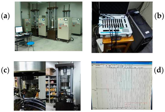
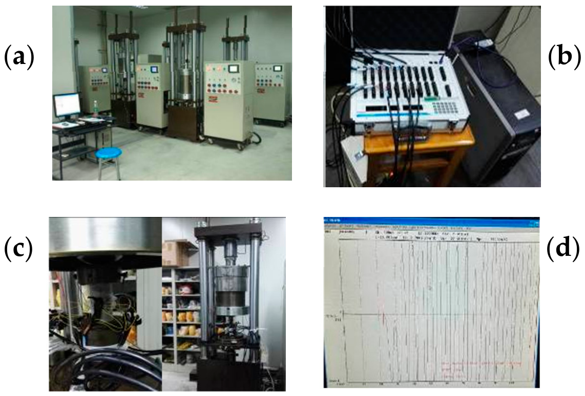
Ambient temperature and humidity significantly affect the time-dependent creep behaviors of foliated soft metamorphic rocks such as sericite phyllite, and fluctuating environmental conditions may interfere with the identification of bedding-controlled anisotropic creep laws. Therefore, all tests were performed under strictly controlled laboratory conditions. With the support of a central air-conditioning and constant-humidity ventilation system, the indoor temperature was stabilized at 23 ± 2 °C and the relative humidity was maintained at (65 ± 5)% RH (Figure 1).
Figure 1.
Test equipment and test results of uniaxial creep and wave velocity: (a) computer-controlled creep testing apparatus, (b) wave velocity testing apparatus, (c) installation and measurement system for uniaxial creep tests, (d) typical P-wave waveform.
The P-wave velocity of sericite phyllite specimens was measured using a Sonic Viewer-SX 5251 ultrasonic tester (OYO Corporation, Tsukuba, Japan) (Figure 1b). This high-precision instrument determines P-wave velocity by recording the travel time of ultrasonic waves penetrating rock specimens. During testing, each specimen was placed steadily between two ultrasonic transducers. A high-voltage pulse was loaded on the transmitting transducer to generate ultrasonic signals, which propagated through the foliated specimen and were eventually acquired by the receiving transducer. Integrated with a 12-bit/50 ns high-speed analog-to-digital converter and digital stacking function, the testing system optimizes the signal-to-noise ratio and achieves precise recognition of ultrasonic travel time. Real-time waveform monitoring and flexible data output functions further guarantee the accuracy and repeatability of ultrasonic test results, providing reliable structural parameter support for analyzing the bedding-dominated anisotropic creep mechanism and long-term service stability of phyllite-stratum tunnel-surrounding rock.
2.2. Specimen Preparation
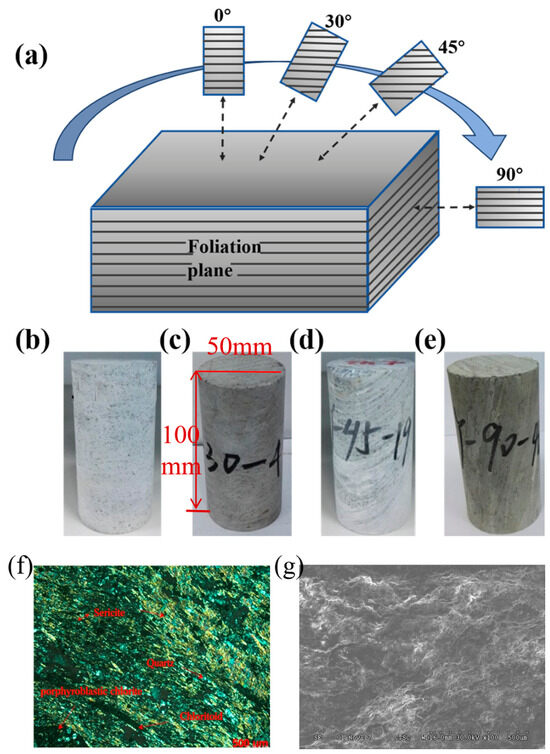
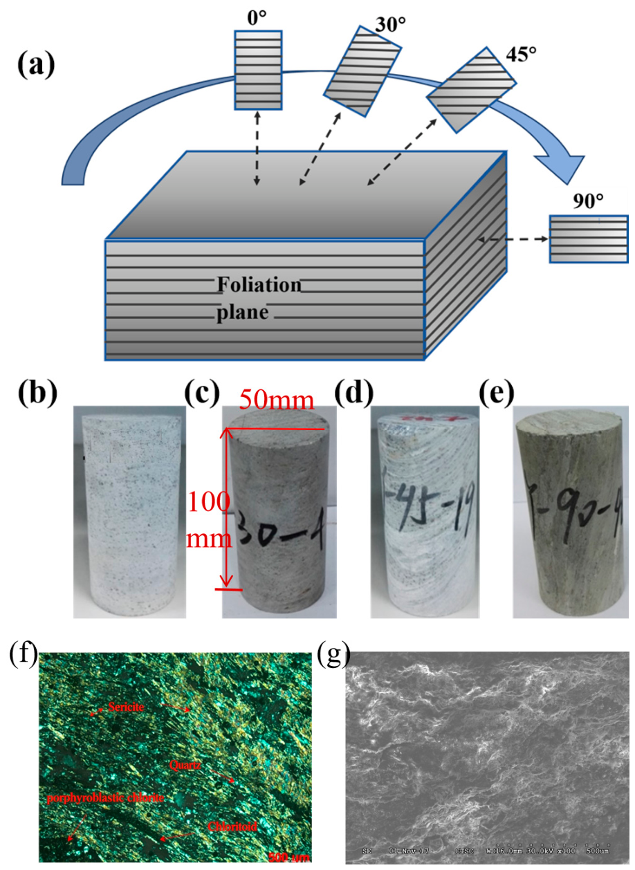
Sericite phyllite specimens in this research were sampled from a tunnel project in Wenchuan. The tunnel-surrounding rock mainly comprises metamorphic sandstone, slate and phyllite of Xinduqiao, Zhuwo and Zagunao Formations, with local carbonaceous phyllite interlayers. The rock blocks collected feature well-developed clear bedding planes. After field sampling, rock blocks were fully sealed and delivered to the laboratory. Standard cylindrical specimens (50 mm in diameter, 100 mm in height) were prepared by core drilling, cutting and surface polishing.
Specimens were drilled at four bedding dip angles of 0°, 30°, 45° and 90° (Figure 2) to reveal the bedding-controlled anisotropic mechanical characteristics of phyllite surrounding rock and its adverse effects on the long-term service safety of tunnel structures. In this manuscript, the foliation dip angle θ is defined as the angle between the axial loading axis and the normal direction of the foliation plane of cylindrical specimens under the creep-loading condition. It should be noted that the angles marked in Figure 2a represent coring orientations within the rock block, which are not equivalent to the loading-state foliation dip angle θ used for data analysis. Dry drilling was adopted for specimen preparation to prevent water infiltration from disturbing internal rock structure and altering mechanical parameters. All specimens were processed with high machining accuracy: the parallelism error of two end faces was controlled within 0.005 cm, and the verticality errors between end faces and the central axis were less than 0.25°. All samples were naturally air-dried to unify initial physical states and exclude the disturbance of inconsistent water content on anisotropic creep test data.
Figure 2.
Coring-direction schematic and typical phyllite specimens with different foliation dip angles. (a) Schematic of sample coring; (b–e) specimens with foliation dip angles of 0°, 30°, 45°, and 90°; (f) cross-polarized micrograph of intact phyllite thin section showing intrinsic mineral-foliation microstructure; (g) SEM secondary-electron view of quasi-static compression fracture surface. Note: the angles in sub-figure (a) represent coring orientations within the rock block, and differ from the loading-state foliation dip angle θ defined in Section 2.2.
Specimens with apparent surface defects, macroscopic cracks or uneven surfaces were screened out first. The remaining qualified samples underwent ultrasonic P-wave tests, and rock integrity was assessed via ultrasonic attenuation features. Specimens with close P-wave velocities were classified into the same group to reduce experimental discreteness. Detailed ultrasonic test data are provided in Section 3. Prior to formal creep testing, one representative and relatively homogeneous specimen was selected from each bedding-angle group for multi-stage uniaxial creep tests.
Representative uniaxial compressive strength (UCS) values obtained from preliminary static compression tests are adopted to design multi-stage creep loading levels. The representative UCS values are 34.86 MPa for 0°, 27.22 MPa for 30°, 24.08 MPa for 45°, and 60.51 MPa for 90°. Note that complete replicate-specimen statistics including mean value and standard deviation are not available for these preliminary tests.
2.3. Experimental Procedure
The multi-stage loading scheme simulates the gradual stress accumulation of surrounding rock after tunnel excavation and support construction, which matches the actual stress evolution law of underground building lining structures. The preliminary static uniaxial compression tests were conducted following the ISRM suggested methods for rock mechanics testing, under displacement-controlled loading at a rate of 0.05 mm/min. The representative UCS values obtained from these tests provide a reference for determining the stepwise stress magnitudes of multi-stage creep tests.
Both single-stage and multi-stage loading methods were adopted in laboratory creep tests. The single-stage loading test applies different constant loads on separate specimens under identical environmental conditions to obtain creep curves at various stress levels for reflecting intrinsic rock mechanical properties. Nevertheless, specimen discreteness, equipment limits and long test cycles hinder its practical application. By comparison, multi-stage loading exerts stepwise increasing stress on one specimen to capture creep responses under multiple stress levels, and equivalent single-stage creep curves can be deduced by the superposition principle. Accordingly, the multi-stage loading scheme was selected for this research, and the detailed test procedures are illustrated below.
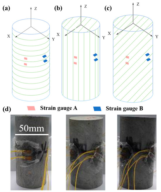
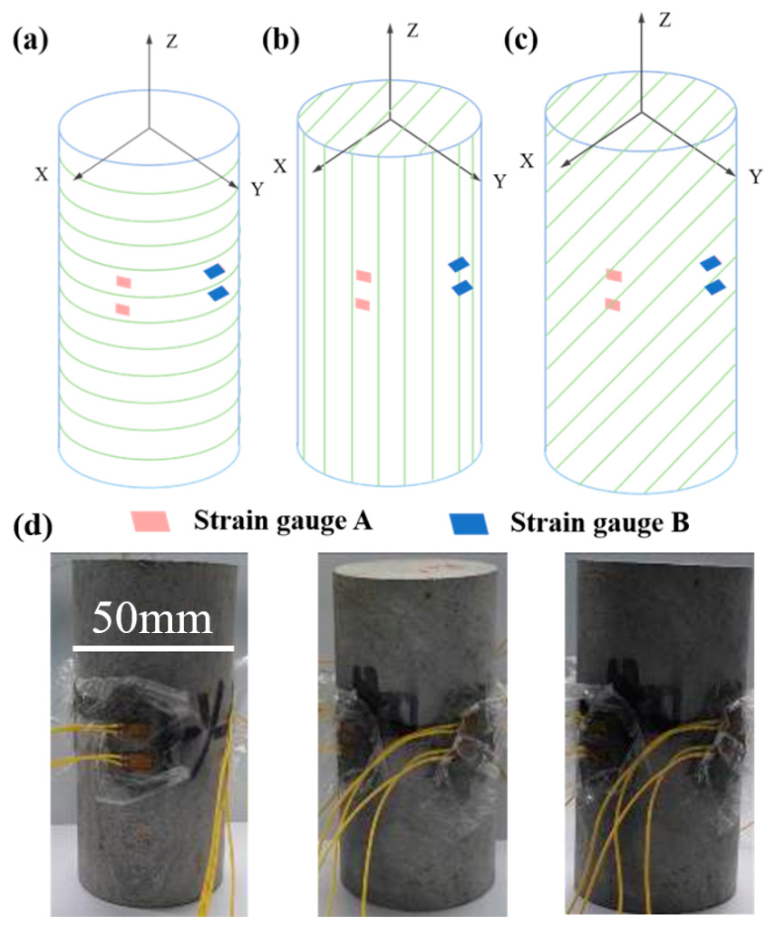
(1) Uniaxial multi-stage creep tests were conducted on phyllite specimens with bedding dip angles of 0°, 30°, 45° and 90°. Circumferential strain gauges were pasted on specimen surfaces to record real-time circumferential deformation during creep, and the layout details are shown in Figure 3. For specimens with inclined bedding planes, subscripts were adopted to differentiate circumferential strains along Direction A and Direction B, enabling quantitative characterization of anisotropic deformation behaviors. Direction A is parallel to the foliation strike, while Direction B is perpendicular to the foliation strike for inclined bedding specimens.
Figure 3.
Schematic and physical photos of strain-gauge arrangement for uniaxial compressive creep tests. (a) = 0°; (b) = 90°; (c) 0° < < 90°; (d) typical rock specimens bonded with strain gauges.
(2) The strain-instrumented specimens were gently installed into the pressure chamber. The hydraulic control system was adjusted to calibrate the base position and guarantee full contact between the specimen and the upper loading platen.
(3) Axial displacement transducers and dial indicators were mounted to track axial deformation. Strain gauges were wired to a static resistance strain tester with shielded cables to synchronously collect circumferential strain data.
(4) Axial load was applied incrementally to reach each preset stress level.
(5) Axial deformation and circumferential strain data were continuously recorded by the matched test control software.
During the test, instantaneous axial deformation and circumferential strain were recorded immediately upon reaching each load level. Data were then collected at intervals of 0.5 min, 1 min, 5 min, 10 min, 15 min and 30 min. Once deformation stabilized, data were sampled roughly every three hours. The overall loading and data acquisition procedure is shown in Figure 1c.
Strain data with a 15 min sampling interval were adopted to judge the onset of steady-state creep for each stress level. Steady-state creep was identified when the fluctuation in the strain increment within a continuous 1 h time window was less than 5% of the average strain increment within this window. The steady-state creep rate is commonly calculated via linear least-squares regression on manually selected stable segments of creep curves, where the initial decelerating-creep portion was excluded [24,25,26]. Only fitting results with a coefficient of determination R2 > 0.90 were adopted for subsequent analysis.
3. Anisotropic Analysis of Phyllite Wave Velocity
Ultrasonic P-wave velocity detection is a rapid field testing method widely applied in the geological survey stage of tunnel underground structures, which can characterize the anisotropic mechanical properties of surrounding rock masses without destructive sampling. With the increasing demand for long-term safety prediction of mountain tunnel structures, systematic study of the P-wave velocity anisotropy of phyllite is essential to promote the application of ultrasonic detection technology in the design stage of phyllite-stratum tunnel structures.
In this study, P-wave velocity measurements were carried out on sericite phyllite specimens with bedding dip angles of 0°, 30°, 45° and 90° to quantitatively characterize the bedding-controlled structural anisotropy of tunnel-surrounding rock. Vaseline was uniformly smeared on both end faces of each specimen as a coupling medium, and ultrasonic transducers were closely fitted to the specimen surfaces to complete the measurement. All ultrasonic tests were implemented at room temperature, and all specimens were maintained under dry, stress-free initial conditions to eliminate external interference with anisotropic test results. The whole test operation and subsequent data processing were performed strictly in line with industry standards. The layout of the ultrasonic test system is shown in Figure 1c.
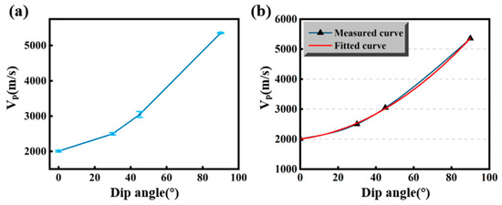
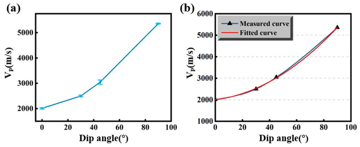
After obtaining the P-wave velocity of phyllite specimens, the anisotropic characteristics of phyllite can be revealed by analyzing the variation in wave velocity among samples with different bedding angles. The P-wave velocity was adopted to characterize the anisotropic behavior in this study. The test results are listed in Table 1, and the corresponding scatter diagram is presented in Figure 4a.
Table 1.
Longitudinal wave velocity test results.
Figure 4.
(a) Longitudinal wave velocity of rock specimens with different foliation dip angles; (b) relationship between longitudinal wave velocity and foliation dip angle.
It can be observed from Table 1 and Figure 4a that the average P-wave velocities of specimens with bedding angles of 0°, 30°, 45° and 90° are 2009.7 m/s, 2499.3 m/s, 3046.3 m/s and 5356.7 m/s respectively, showing obvious anisotropy. The anisotropic wave velocity characteristics of phyllite are closely related to the directional arrangement of mineral particles and internal microcracks. The average P-wave velocity was fitted against the bedding angle, and the fitting curve is shown in Figure 4b. The fitting equation is expressed as follows:
where θ is the foliation dip angle (°), the unit of longitudinal wave velocity is m/s, and the correlation coefficient is 0.998.
It should be noted that this quadratic polynomial is only an empirical interpolation derived from the mean P-wave velocities of the four tested bedding orientations for the present batch of sericite phyllite specimens. It is not a general constitutive relationship applicable to all foliated phyllite rock masses. Owing to the limited number of foliation angles, a high correlation coefficient cannot guarantee its universality. Caution should be taken when extrapolating this formula to untested dip angles or other phyllite samples.
4. Results of Uniaxial Compressive Creep Tests
The uniaxial compressive strength of phyllite surrounding rock with different bedding angles is the key basis for determining the design load of tunnel primary support and secondary lining. The graded stress levels in this creep test are set according to the measured uniaxial strength, simulating the sustained long-term load borne by tunnel lining structures after excavation. Based on the laboratory uniaxial compression test results, the uniaxial compressive strength of specimens with various bedding angles was determined, which was used to set the multi-stage load levels for uniaxial creep tests, as listed in Table 2. Due to the prominent strength anisotropy of sericite phyllite, direct comparison under identical absolute stress may produce biased interpretation of intrinsic creep characteristics. Therefore, the normalized stress ratio (σ/σc) is provided in Table 2 to assist anisotropy evaluation, which eliminates the influence of strength difference among specimens with different foliation dip angles. Absolute-stress-based descriptions are still retained in the manuscript for practical engineering reference. The uniaxial creep curves of phyllite under different axial stress levels for each bedding angle were obtained and are displayed in Figure 5.
Table 2.
Stress levels for graded-loading uniaxial creep tests.
Figure 5.
Uniaxial creep time-dependent curves of phyllite specimens with different bedding dip angles: (a) dip angle 0°, (b) dip angle 30°, (c) dip angle 45°, (d) dip angle 90°.
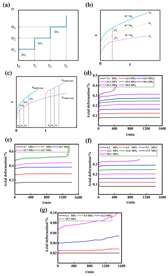
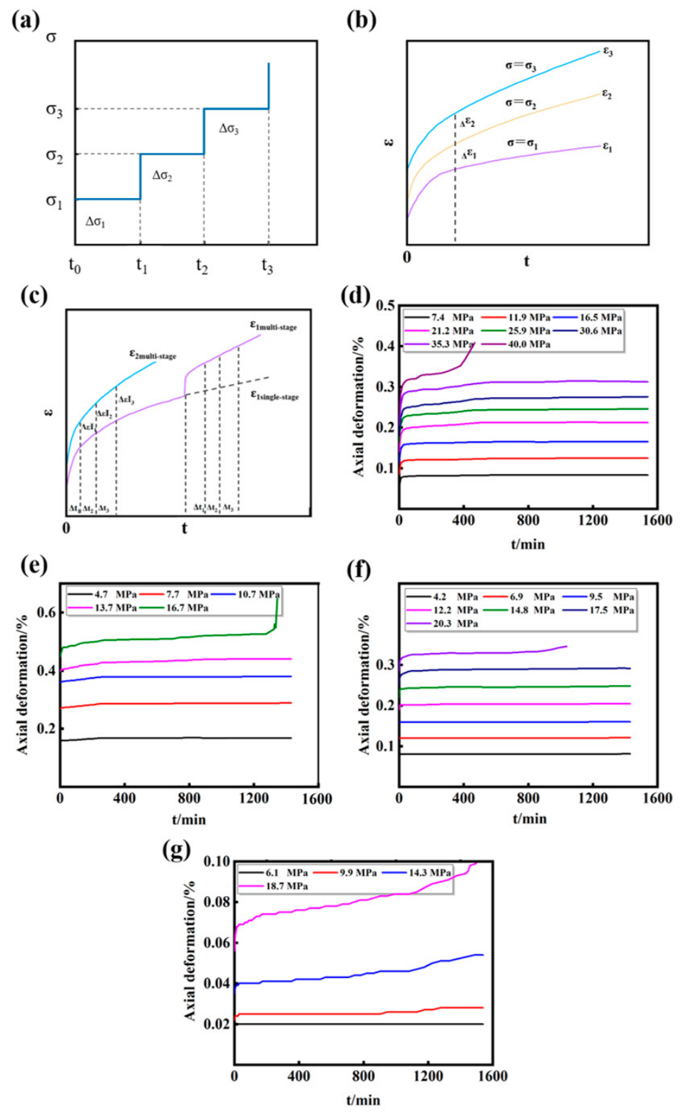
Rock creep deformation is governed by applied stress, loading duration and stress history. In multi-stage loading creep tests, the creep curve of each subsequent stage is affected by the deformation induced by previous load levels. Therefore, the Boltzmann linear superposition principle is widely adopted to convert multi-stage creep curves into equivalent single-stage creep curves, which is also known as the hereditary creep theory [27]. For the multi-stage loading scheme adopted in this study (Figure 6a), the load of the i-th stage is expressed as:
Figure 6.
Graded-loading and creep test results: (a) graded-loading history, (b) single-stage creep curve, (c) graded-loading creep curve; axial multi-stage creep curves of phyllite specimens with different bedding dip angles: (d) 0°, (e) 30°, (f) 45°, (g) 90°.
In a single-stage loading test, the stress remains constant with time (Figure 6b). Denoting the stress by , the creep curve can be expressed as:
where is the creep compliance, and the single-stage stress is defined as .
The creep induced by the change in single-stage stress from to can be expressed as:
Under multi-stage loading conditions (Figure 6c), the creep curve at the level loading stage can be expressed as:
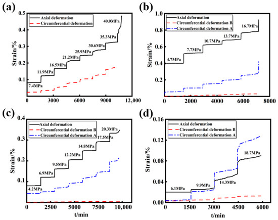
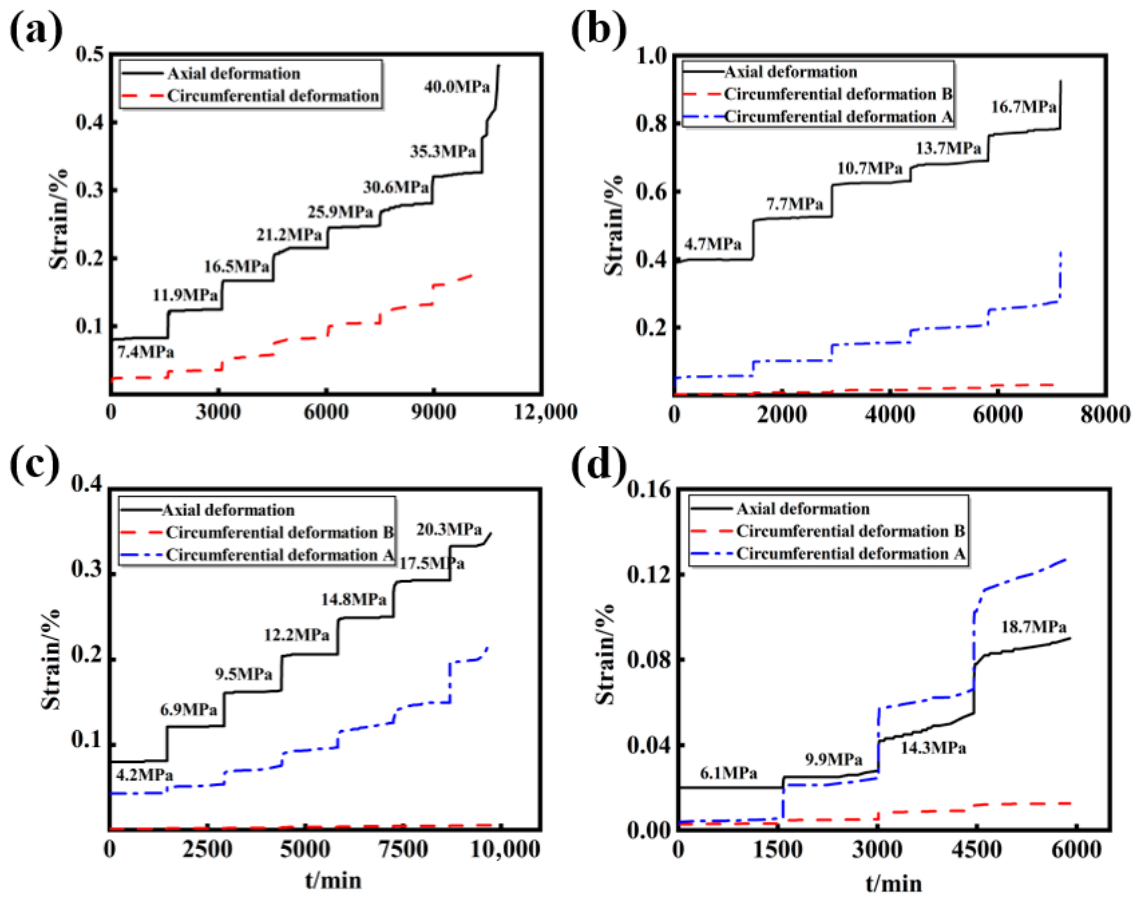
It should be noted that the Boltzmann linear superposition principle is valid only for linear viscoelastic deformation under low-to-moderate stress with negligible micro-damage. This principle is no longer applicable to high-stress creep stages accompanied by microcrack propagation, damage accumulation and accelerating creep. Based on the Boltzmann linear superposition principle, multi-stage creep test data were processed to obtain equivalent single-stage creep curves under different low-to-moderate stress levels dominated by linear viscoelasticity. After superposition calculation, the axial and circumferential creep curves of phyllite specimens are presented in Figure 6 and Figure 7, respectively. It should be emphasized that these reconstructed curves are only valid for the linear-viscoelastic stress range and cannot be extended to nonlinear damage-dominated creep stages. This principle converts multi-stage loading test data into equivalent single-stage creep curves, which can directly provide time-dependent deformation parameters for finite-element long-term durability simulations of tunnel lining structures within this effective stress interval.
Figure 7.
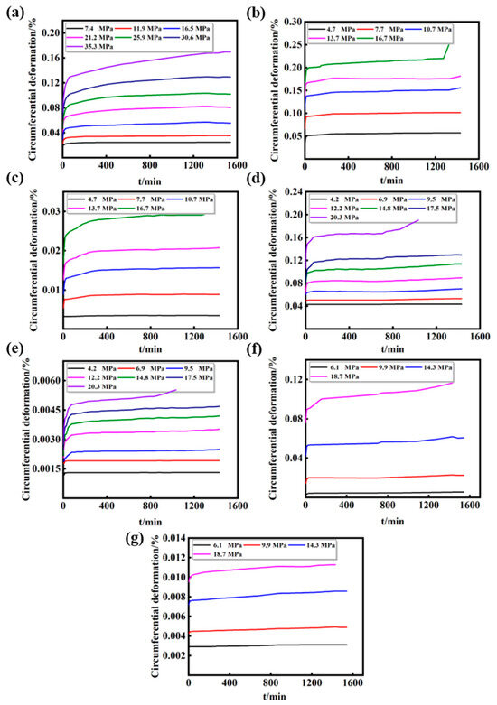
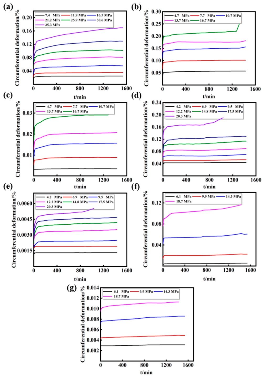
Circumferential multi-stage creep curves of rock specimens with different dip angles: (a) 0°, (b) 30° (Direction A), (c) 30° (Direction B), (d) 45° (Direction A), (e) 45° (Direction B), (f) 90° (Direction A), (g) 90° (Direction B).
5. Anisotropic Analysis of Creep Behavior
5.1. Specimens with Horizontal Bedding Planes
5.1.1. Axial Strain Behavior
As the creep deformation behavior of phyllite is significantly controlled by bedding orientation, the creep evolution law differs greatly under different angles between load and bedding plane. When the loading direction is perpendicular to the bedding plane, the phyllite exhibits typical stage-based creep characteristics, as illustrated in Figure 6d. At low stress levels, the rock specimens undergo instantaneous strain, decelerating creep and steady-state creep. When the applied stress approaches the failure threshold, the specimens experience the above three stages and subsequently enter unsteady accelerating creep, eventually leading to rock failure. Both instantaneous strain and creep strain increase with the rise in stress level, and instantaneous strain dominates the total deformation. The proportion of instantaneous strain in intact specimens ranges from 63.8% to 67.1% under different stress levels, while damaged specimens show a higher proportion of 82.3~91.5%.
Under low-stress conditions, only instantaneous deformation and weak decelerating creep occur, and steady-state creep is barely observed. At the stress level of 7.4 MPa, the instantaneous axial strain is 0.053%. The axial strain increases by only 0.027% after 55 min of decelerating creep, with the creep rate approaching zero. After 1540 min of continuous loading, the additional axial strain is merely 0.003%, which is negligible. This phenomenon is mainly attributed to the rapid compaction of internal microcracks under vertical loading. The compression deformation of microcracks exceeds the elastic deformation of the rock matrix, resulting in prominent instantaneous strain and limited creep deformation under low axial stress.
The axial creep deformation increases significantly with the elevation of axial stress. At 21.2 MPa, the instantaneous strain reaches 0.14%, and the total axial strain increases to 0.20% after 66 min of decelerating creep, which is nearly ten times that under 7.4 MPa. The creep curve presents a slight convex feature, and the axial strain only increases by 0.012% after 1540 min of steady-state creep, reflecting complete three-stage creep characteristics. When the stress increases to 40 MPa, the specimen undergoes short-term decelerating and steady-state creep, followed by a sharp strain increase at 351 min. The specimen enters the accelerating creep stage and finally fails completely. For tunnel structures excavated parallel to horizontal foliation planes, low surrounding rock stress only causes slight instantaneous compression of rock mass, while high long-term stress will trigger continuous accelerating creep, bringing a high risk of overall extrusion damage to tunnel lining.
5.1.2. Circumferential Strain Behavior
The circumferential deformation of phyllite presents obvious anisotropic characteristics controlled by bedding planes. The lateral strain–time curves of specimens are shown in Figure 7a, where outward circumferential expansion is defined as positive strain. Similar to axial deformation, both instantaneous lateral strain and creep deformation increase gradually with rising stress levels, and all curves exhibit typical multi-stage creep characteristics. The proportions of instantaneous lateral strain in total strain under each load level are 75%, 62.8%, 51.7%, 51.3%, 45.5%, 47.3% and 42.9%, showing a continuous declining trend. When the deviatoric stress reaches the fifth stage of 25.9 MPa, this proportion remains roughly constant.
Only instantaneous lateral deformation and slight decaying creep occur under low stress. At 7.4 MPa, the instantaneous lateral strain is 0.018%. The strain merely rises by 0.004% after 28 min of decaying creep, and the creep rate approaches zero. After 1540 min of loading, the additional lateral strain is only 0.002%. When the axial stress increases to 21.2 MPa, the instantaneous lateral strain reaches 0.14%, and the total strain grows by 0.24% after 30 min of decaying creep, which is more than ten times that under the first load stage. The creep curve presents a slight convex shape, and the lateral strain increases by 0.04% after 1540 min of steady-state creep, covering three complete stages: instantaneous strain, decaying creep and steady-state creep. When the stress reaches 40 MPa, after a short period of decaying and steady-state creep, the lateral strain surges sharply as the specimen enters the accelerating-creep regime. At final failure, the axial instantaneous strain and creep strain increase by 0.127% and 0.066%, respectively, while the lateral instantaneous strain and creep strain only increase by 0.043% and 0.062%.
5.2. Specimens with Vertical Bedding Planes
5.2.1. Axial Strain Behavior
Bedding orientation controls the axial creep deformation of sericite phyllite, and vertical bedding specimens exhibit axial deformation laws different from those of horizontal bedding specimens. When the loading direction is perpendicular to bedding planes, Figure 6g shows that both instantaneous strain and creep strain rise with the increase in stress level, and the specimens present standard multi-stage creep characteristics. Under low stress, the deformation consists of instantaneous strain, decelerating creep and steady-state creep. When the applied stress approaches the failure stress, the specimens go through the above three stages and then enter unsteady accelerating creep, which eventually causes rock failure. Particularly for specimens with horizontal bedding, only instantaneous deformation occurs at low stress such as 6.1 MPa.
The proportion of instantaneous strain in total strain exceeds 50%, following the same variation trend as specimens with horizontal bedding planes, while the axial deformation magnitude is relatively lower. The proportions of instantaneous strain for intact specimens under each stress level are 100%, 78.6%, 64.8% and 56.6%, and those for damaged specimens are 89.4%, 88.9%, 91.4% and 79.1%.
Only instantaneous elastic deformation appears at low stress levels. At 6.1 MPa, merely 0.02% instantaneous strain is generated without subsequent creep deformation, and the creep rate remains zero. When the axial stress rises to 14.3 MPa, the instantaneous strain reaches 0.035%, and the strain increases by 0.004% after 21 min of decelerating creep with a constant creep rate. After 1540 min of creep, the strain grows by an additional 0.015%. At the axial stress of 18.7 MPa, the instantaneous strain is 0.056%. The specimen enters steady-state creep after 15 min of short decelerating creep with an obviously convex creep curve, and the accelerating creep stage starts at 1128 min.
5.2.2. Circumferential Strain Behavior
The circumferential strain–time curves of specimens are displayed in Figure 7f,g, where outward circumferential expansion is defined as positive strain. Similar to axial deformation, both instantaneous circumferential strain and creep deformation increase gradually with elevated stress levels, and all curves exhibit standard multi-stage creep characteristics. It can be observed from Figure 7f,g that the strain magnitude in Direction B is lower than that in Direction A, which originates from the inherent anisotropy of foliated phyllite.
For intact specimens, the average proportions of instantaneous circumferential strain in total strain along Direction A and Direction B are 56.9% and 77.3%, respectively. For damaged specimens, the corresponding average ratios reach 75.2% and 87.5%, indicating that the proportion of instantaneous strain in Direction B is consistently higher than that in Direction A. The growth rates of instantaneous strain and creep strain along Direction A are larger than those along Direction B. In addition, the proportion of circumferential strain in Direction B to total circumferential strain decreases monotonically with rising stress. The evolution laws of circumferential strain along Directions A and B are identical, with only quantitative differences. Therefore, the circumferential deformation along Direction A is taken as the typical case for detailed analysis.
Only instantaneous strain and slight decelerating creep occur under low stress. At the load level of 6.1 MPa, an instantaneous circumferential strain of 0.003% is generated immediately upon loading. The strain rises merely by 0.0012% after 28 min of decelerating creep, and the creep rate approaches zero. Minor fluctuation in circumferential strain appears at 820 min after loading. This phenomenon can be explained by the heterogeneous nature of rock; tiny dislocation of internal mineral particles under load leads to slight strain fluctuation.
When the axial stress increases to 14.3 MPa, the instantaneous elastic circumferential strain reaches 0.042%. The strain increases by 0.01% after 21 min of decelerating creep, and the creep rate then remains constant. The circumferential strain only rises by 0.008% after 1540 min of continuous creep. When the axial stress is raised to 18.7 MPa, the specimen presents a complete four-stage creep curve.
5.3. Specimens with Inclined Bedding Planes
5.3.1. Axial Strain Behavior
The axial multi-stage creep curves of specimens with a bedding dip angle of 30° are shown in Figure 6e. Both instantaneous strain and creep strain rise with the increase in stress level, and instantaneous strain dominates the total deformation. The proportions of instantaneous strain under each load level are 86.4%, 90.0%, 89.9%, 90.5% and 85.2%, respectively. With the extension of loading duration, both the bedding weak planes and rock matrix are damaged, which contributes to the growth of creep strain. Irregular fluctuations in axial deformation are observed under low stress levels, which can be attributed to heterogeneous fracture inside the rock. Non-uniform deformation occurs at local weak zones with low rock strength, leading to fluctuating axial strain values.
The multi-stage creep curves of specimens with a bedding dip angle of 45° are presented in Figure 6f. Instantaneous strain and creep strain increase gradually with elevated stress, and instantaneous strain accounts for most of the total strain. The corresponding ratios at each stress level are 98.8%, 97.6%, 95.8%, 92.2%, 88.7%, 85.9% and 82.6%. The creep evolution law under various stress levels is consistent with that of specimens with a bedding angle of 30°.
All specimens with inclined bedding planes exhibit typical multi-stage creep characteristics. Under low stress, the deformation process includes instantaneous strain, decelerating creep and steady-state creep. When the applied stress approaches the failure threshold, the specimens enter the accelerating creep stage after the above three phases and eventually collapse. Both instantaneous strain and creep strain of inclined bedding specimens are larger than those of vertical bedding specimens. The proportion of creep strain for 45° specimens is higher than that for 30° specimens. This is mainly because specimens with a bedding angle of 45° contain more weak interlayer materials within bedding planes. Under deviatoric stress, the damage degree of bedding weak planes is much more severe than that of the rock matrix.
5.3.2. Circumferential Strain Behavior
The circumferential multi-stage creep curves of specimens with a bedding angle of 30° are shown in Figure 7b,c, where outward circumferential expansion is defined as positive strain. Directions A and B represent circumferential measuring directions within and perpendicular to the foliation plane, respectively (see Section 2.3). The test results indicate that the average proportions of instantaneous strain in the total strain in Directions A and B are 76.2% and 62.8%, respectively, both exceeding 50%. As the axial stress increases from 4.7 MPa to 13.7%, the instantaneous strains in Directions A and B increase by 0.112% and 0.012%, while the creep strains increase by 0.012% and 0.007%, respectively. The circumferential creep behavior presents an opposite trend to the axial creep, indicating that deviatoric stress induces a more significant hardening effect in the circumferential direction, which is consistent with the behavior of vertically bedded specimens.
For specimens with a bedding angle of 45°, the circumferential creep curves are displayed in Figure 7d,e. The average proportions of instantaneous strain in Directions A and B are 76.7% and 70.5%, respectively. The instantaneous strain dominates the total deformation, and its proportion is generally higher than that of 30° specimens. When the axial stress rises from 4.2 MPa to 12.2 MPa, the instantaneous strains in Directions A and B increase by 0.02% and 0.001%, and the corresponding creep strains increase by 0.026% and 0.001%.
With the increase in stress level, the circumferential deformation exhibits typical staged creep characteristics. Specimens undergo instantaneous strain, decelerating creep, and steady-state creep under low-stress conditions. When the stress approaches the failure level, the specimens enter an unstable accelerating creep stage after the three basic creep stages and eventually fail, which is consistent with the evolution law of axial strain. Both instantaneous and circumferential creep strains increase monotonically with increasing stress. The circumferential strain of inclined bedding specimens is larger than that of vertical bedding specimens. Affected by rock anisotropy, the strain magnitude and growth rate in Direction B are lower than those in Direction A. In addition, the deviatoric stress induces more severe damage in 45° specimens than in 30° specimens, which further agrees with the axial creep characteristics.
5.4. Analysis of Recoverable Deformation
Under each load level, the recoverable strain of rock specimens consists of instantaneous elastic strain and time-dependent recoverable viscoelastic strain, both of which are closely dependent on the applied stress level. The instantaneous strain can be fully recovered immediately after unloading, while the recoverable viscoelastic strain rebounds gradually over time.
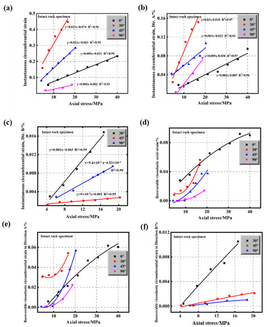
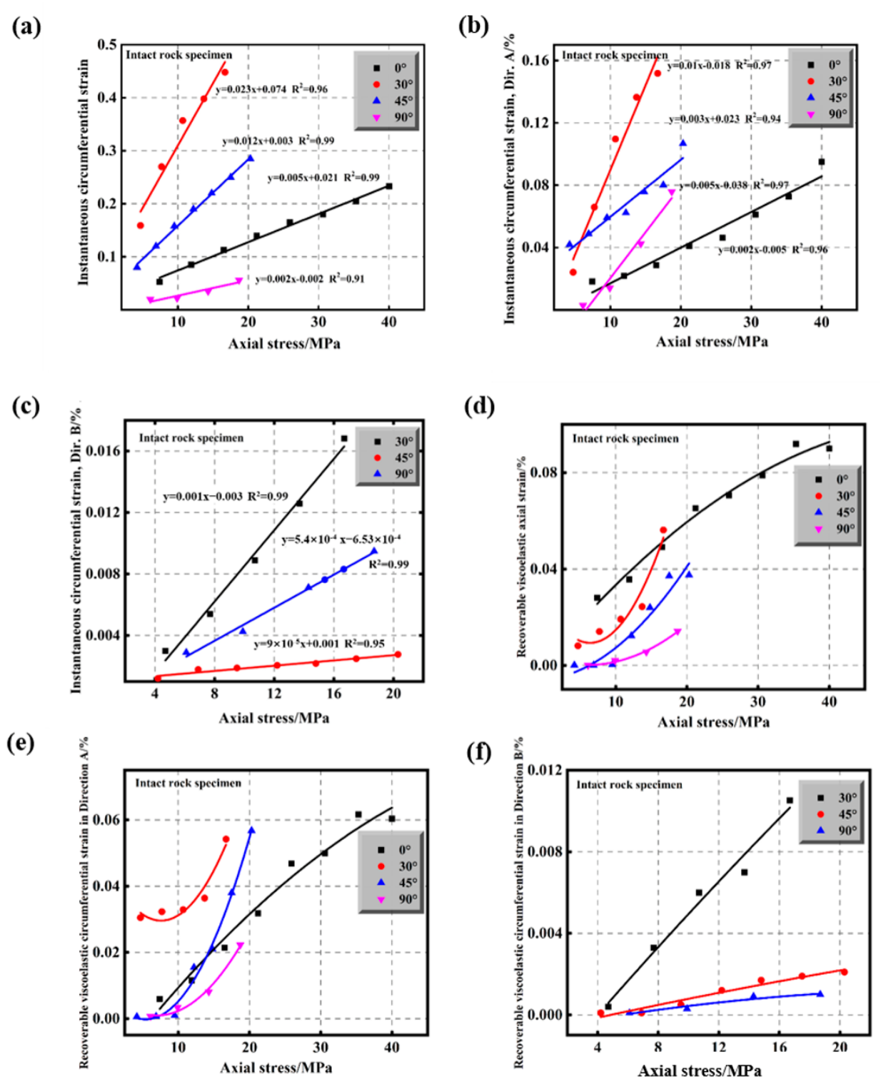
Figure 8 presents the relationship between instantaneous strain and axial stress under various stress levels. It is indicated that both axial and circumferential instantaneous strains exhibit a favorable linear correlation with axial stress and increase monotonically with rising stress. Nevertheless, specimens with different bedding angles show distinct strain growth rates.
Figure 8.
Relationship between stress levels and instantaneous strain and recoverable viscoelastic strain: (a) relationship between stress levels and instantaneous axial strain, (b) relationship between stress levels and instantaneous circumferential strain in Direction A, (c) relationship between stress levels and instantaneous circumferential strain in Direction B, (d) trend of recoverable viscoelastic axial strain, (e) trend of recoverable viscoelastic circumferential strain in Direction A, (f) trend of recoverable viscoelastic circumferential strain in Direction B.
The relationship between applied stress and recoverable viscoelastic strain is illustrated in Figure 8. The viscoelastic strain increases continuously with the elevation of stress. At low stress levels, the viscoelastic strain varies linearly with axial stress. With further stress increase, internal damage accumulates progressively within the rock mass, which presents prominent nonlinear evolution features. Instantaneous elastic strain can be completely released after tunnel excavation unloading, while time-dependent viscoelastic recoverable strain will produce delayed lining extrusion, which must be considered in long-term deformation monitoring of tunnel structures.
5.5. Analysis of Creep Deformation
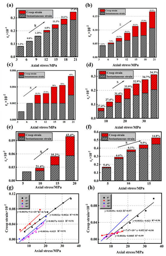
Creep deformation is time-dependent deformation under constant stress. Symbols are adopted to denote total strain (instantaneous elastic strain plus creep strain), creep strain and the creep strain ratio, which follow the corresponding formula. Axial and circumferential creep laws are analyzed using specimens with a 45° bedding angle, and their creep strain variations are shown in Figure 9a–c. Both axial and circumferential creep strains rise with stress, alongside an increasing creep ratio. For the tested representative specimens, the circumferential creep ratio is higher, indicating more prominent circumferential creep that impairs surrounding rock stability.
Figure 9.
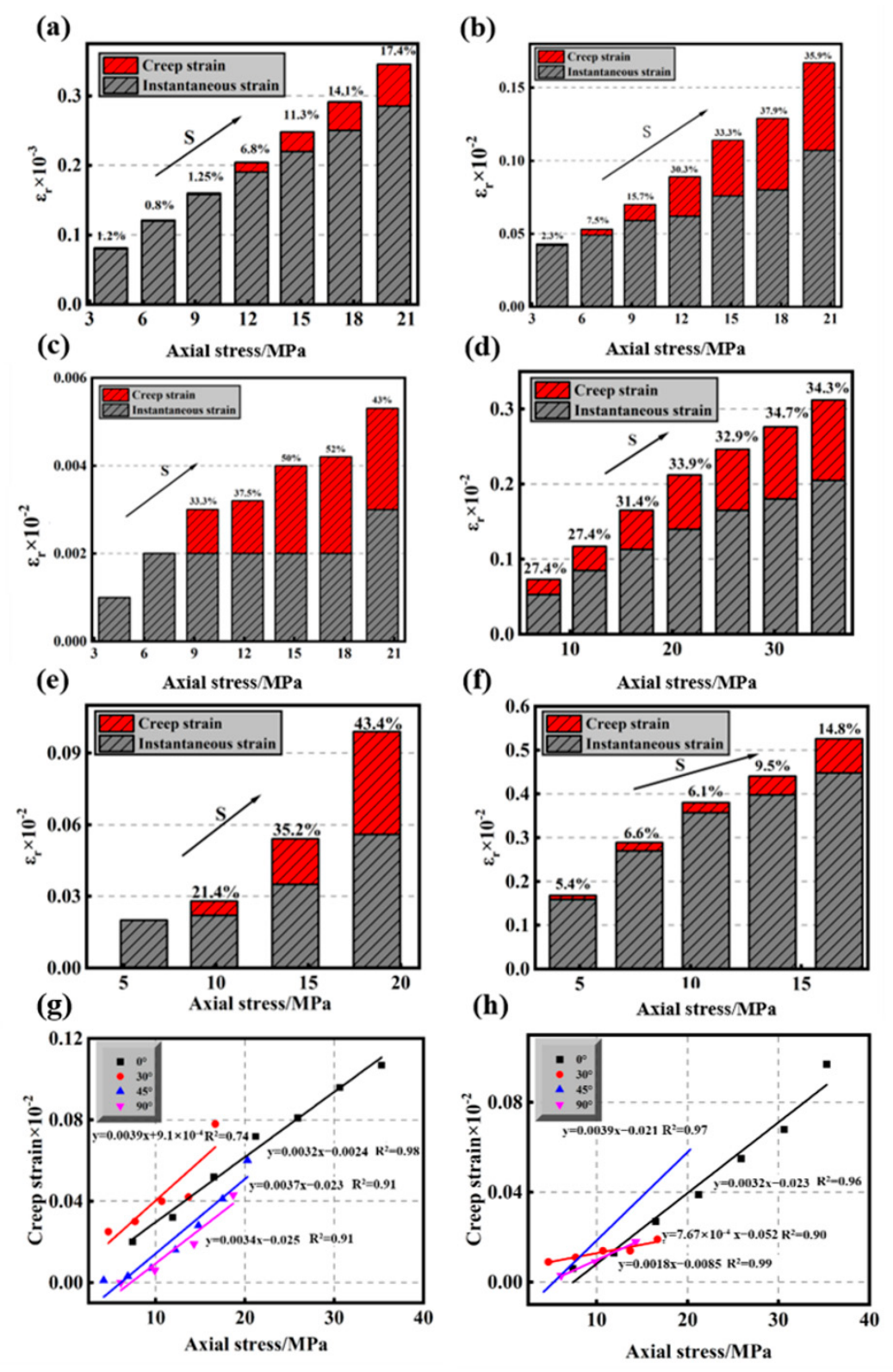
Axial and circumferential instantaneous strain and creep strain of rock specimens with a 45° foliation inclination: (a) axial instantaneous strain and creep strain, (b) circumferential instantaneous strain and creep strain in Direction A, (c) circumferential instantaneous strain and creep strain in Direction B. Axial instantaneous strain and creep strain of rock specimens with different foliation inclinations: (d) 0°, (e) 30°, (f) 90°. Relationship between axial stress and creep strain: (g) axial direction, (h) circumferential direction.
Figure 9d–f displays axial instantaneous and creep strains of intact specimens at 0°, 30° and 90°. Combined with Figure 8a, the axial creep ratio presents a U-shaped distribution (high at both ends), consistent with the anisotropic trend of rock strength. High stress accelerates creep, yet a large creep ratio does not equal a large absolute creep value. For example, the 90° specimen has a creep ratio of 43.4% at the fourth load stage, but its creep strain only reaches 0.043%, smaller than the final-stage values of 0.107%, 0.078% and 0.06% for 0°, 30° and 45° specimens.
Creep strain is strongly correlated with stress level. The regression fitting between axial stress and axial/circumferential creep strains is plotted in Figure 9g,h, showing satisfactory linear correlations. For the tested representative specimens, the circumferential creep strain ratio is higher than the axial value, revealing that lateral expansion creep is the primary control factor of tunnel lining structural deterioration and long-term stability loss. It should be pointed out that the above comparative analysis of creep deformation is implemented based on absolute axial stress. Due to the strong strength anisotropy of sericite phyllite, specimens with different bedding dip angles reach different relative load-bearing states even under the same absolute stress. Therefore, the normalized stress ratio is introduced for auxiliary analysis.
5.6. Analysis of Creep Rate
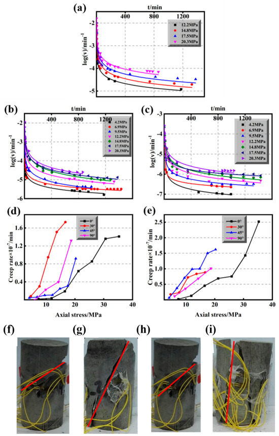
Rock creep is divided into decelerating, steady-state and accelerating creep stages. At the initial creep stage, the creep rate decays over time and reaches a constant value to form steady-state creep; subsequently, the creep rate rises and the specimen enters accelerating creep. Strictly speaking, steady-state creep is only an approximate classification based on experimental phenomena rather than an independent physical stage, and creep strain is closely related to the creep rate. Figure 10a–c present the scatter trend of the creep rate for specimens with a 45° bedding angle. It can be found that the creep rate decreases gradually with time and finally stabilizes under each stress level. The identification criterion, regression time interval and uncertainty evaluation of the steady-state creep rate are described in detail in Section 2.3.
Figure 10.
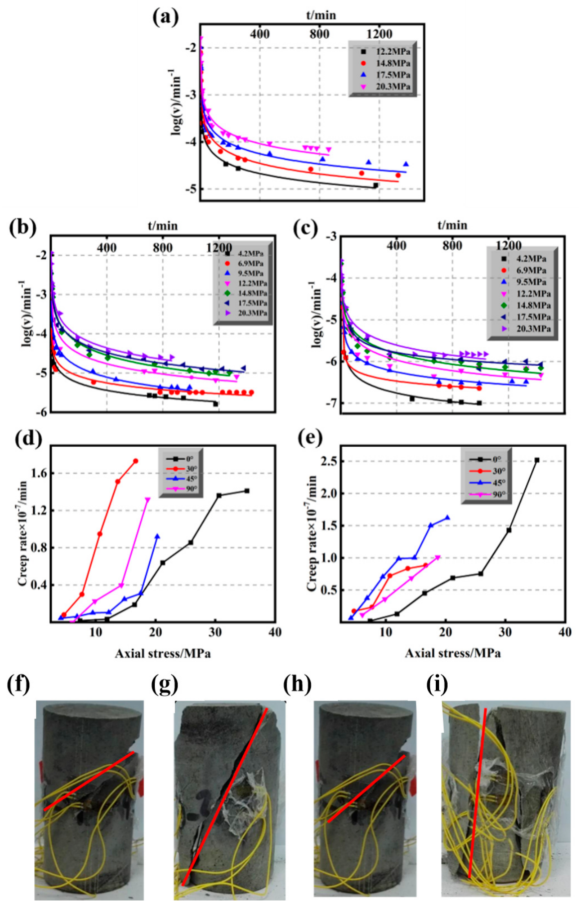
Creep responses of phyllite specimens. (a–c) Axial and circumferential creep-rate evolution for Direction A and B; (d,e) axial and circumferential steady-state creep rate versus axial stress. Typical failure modes ((f) 0°, (g) 30°, (h) 45°, (i) 90°) photographed after long-term constant-stress creep rupture.
To analyze the anisotropy of the steady-state creep rate, Figure 10d,e plot the steady-state creep rate polyline diagrams in the axial direction and circumferential Direction A, respectively. The steady-state creep rate rises nonlinearly with increasing stress, and the nonlinearity becomes more prominent at higher stress. Distinct differences in the creep rate exist among specimens with various bedding angles under identical stress.
For the tested representative specimens, axially, specimens with horizontal bedding (0°) have the minimum creep rate, while those with 30° bedding exhibit the maximum value. Circumferentially, the creep rate of vertical bedding (90°) specimens exceeds that of horizontal bedding (0°), and specimens with 45° bedding show the highest creep rate. The steady-state creep rates in axial and circumferential directions are inconsistent under the same stress. It is observed that the creep evolution of axial and circumferential directions lacks strict consistency. Specimens with inclined bedding present more severe creep behavior, which imposes worse adverse effects on surrounding rock stability. The steady-state creep rate rises nonlinearly with stress. However, it should be emphasized that the present results are laboratory-scale material characterizations for sericite phyllite. The actual tunnel-surrounding rock is subjected to complex three-dimensional stress, confining pressure, groundwater, discontinuities, excavation unloading and rock–support interaction, which are not reproduced in this uniaxial creep study. Therefore, the present data cannot be directly applied to quantify the long-term deformation rate or service-life threshold of tunnel supports. Quantitative service-life prediction requires further constitutive modeling, field validation, and triaxial or true-triaxial creep tests, which are beyond the scope of the present work.
The observed anisotropic trend that foliation orientation dominates creep deformation and failure characteristics is qualitatively consistent with previous experimental investigations on phyllite and foliated metamorphic rocks [18,19,27,28,29]. Nevertheless, the relative-magnitude ranking of steady-state creep rates among different bedding angles in this work is derived from pre-screened individual specimens, and statistical verification from repeated parallel tests is still required.
Similarly, for creep-rate comparison among different bedding orientations, the normalized stress should be considered to reasonably evaluate the inherent anisotropic creep behavior of sericite phyllite. The qualitatively dominant failure mode obtained from each creep specimen is consistent with existing experimental observations on foliated metamorphic rocks, which supports the rationality of the present test results. It should be noted that only one screened representative specimen was tested for each bedding dip angle in this study. Further extensive repeated laboratory creep tests will be required in future work to verify the repeatability of these failure-mode characteristics.
5.7. Failure Modes
The anisotropy of phyllite leads to distinct creep failure modes for specimens with different bedding angles, as shown in Figure 10f,i. Specimens with horizontal bedding exhibit shear failure cutting across weak bedding planes; vertically bedded specimens experience tensile splitting failure; inclined specimens mainly undergo shear-slip failure along bedding planes.
For horizontally and vertically bedded specimens, the rock matrix bears most of the load. Longer creep duration enables full damage propagation in both axial and circumferential directions, resulting in more severe fragmentation. For rock masses with horizontal and vertical bedding under uniform in situ stress, long-term creep may potentially produce heavily fragmented surrounding rock, which could induce continuous progressive damage of the tunnel support system.
In addition to the geometric effect of the bedding dip angle, the directional arrangement of sheet-like sericite minerals also participates in the anisotropic creep behavior. The preferred orientation of sericite grains is closely coupled with macroscopic bedding planes, and these two factors may jointly contribute to the remarkable creep response observed for specimens with inclined bedding. It should be noted that the current test data cannot fully decouple the respective contributions of mineral fabric and bedding structure.
5.8. Limitations of the Present Study
(1) All creep tests in this work were conducted under uniaxial zero-confining-pressure conditions. Accordingly, the test results are mainly applicable to the unsupported surrounding-rock condition right after tunnel excavation, and the obtained quantitative creep parameters cannot be directly extrapolated to high-stress or triaxial in situ stress states for field design, as confining pressure can alter the bedding-controlled creep responses of sericite phyllite. Triaxial creep tests with various confining pressures will be carried out in future work.
(2) Multi-stage creep experiments involve substantial time consumption. This study mainly focuses on the qualitative anisotropic creep characteristics of sericite phyllite, and one pre-screened representative specimen was tested for each foliation dip angle. Accordingly, the relative-magnitude comparison of creep rates among different angles is derived from these individual specimens. The UCS values adopted for loading-scheme design and the Boltzmann-superposition-reconstructed single-stage creep curves are also obtained without additional replicate-specimen statistics and independent single-stage creep validation, respectively. In addition, the accelerating-creep phase occurs transiently right before specimen rupture, making full reliable duration-related data difficult to acquire. Follow-up repeated laboratory tests are expected to provide supplementary statistical information, validation evidence and further insights into accelerating-creep behaviors.
(3) The interpretations of weak-plane dominance and matrix-skeleton damage in this paper are macroscopic inferences derived from creep curves and failure morphologies, since post-creep fracture-surface SEM data are unavailable for fully damaged failed specimens. Cross-rock comparative analysis of foliated metamorphic rocks is also absent in the present study. Further microscopic monitoring experiments and multi-rock-type comparisons will help reveal the underlying micromechanical creep mechanisms.
6. Conclusions
This study conducted multi-stage uniaxial compression creep tests on sericite phyllite, a typical surrounding rock of mountain tunnel structures, to systematically investigate the anisotropic creep characteristics and full-stage time-dependent deformation laws of foliated soft rock. The main conclusions and corresponding engineering implications for underground building design are summarized as follows:
(1) Affected by internal microcracks and directional mineral arrangement, phyllite exhibits prominent anisotropy in longitudinal wave velocity. The wave velocity increases with the bedding dip angle at an accelerating rate, and their relationship can be well fitted by a quadratic polynomial.
(2) Phyllite presents typical staged creep behavior, including instantaneous strain, decelerating creep, steady-state creep, and unsteady accelerating creep under high stress. Both instantaneous and creep strains increase linearly with stress, and the proportion of creep strain in total strain rises gradually. The recoverable viscoelastic strain and steady-state creep rate show obvious nonlinear growth with increasing stress, and the nonlinearity is enhanced at high stress levels. For the tested representative specimens, obvious creep anisotropy is observed in phyllite: specimens with inclined bedding exhibit the most significant creep response, while vertically bedded specimens show the weakest creep behavior.
(3) Phyllite with different bedding angles possesses distinct creep failure modes. Interpretations below are macroscopic inferences derived from creep curves and failure morphologies. Horizontal bedding phyllite fails via progressive deformation of weak aggregates and hard particle skeletons. For vertical bedding phyllite, synergistic deformation of weak medium and hard skeletons finally causes skeleton damage and accelerating creep failure. For inclined bedding phyllite, weak and hard components bear loads jointly and produce synchronous creep damage. The weak bedding structure fails preferentially, resulting in shear-slip failure along the bedding plane.
Author Contributions
Conceptualization, J.H.; methodology, J.H. and K.M.; software, K.M., Y.H., L.L. and K.C.; validation, J.H., K.M., J.J. and K.C.; formal analysis, Y.H. and L.L.; data curation, Y.H. and J.J.; writing—original draft preparation, Y.H.; writing—review and editing, J.H. and Y.H.; funding acquisition, L.L. All authors have read and agreed to the published version of the manuscript.
Funding
This research was funded by the Support Program of Henan Province University Science and Technology Innovation Team, grant number 24IRTSTHN010; and the Postgraduate Education Reform and Quality Improvement Project of Henan Province, grant number YJS2026YBGZZ03. The article processing charge (APC) was funded by the Support Program of Henan Province University Science and Technology Innovation Team, grant number 24IRTSTHN010.
Data Availability Statement
Data is contained within the article.
Acknowledgments
This project was supported by the Support Program of Henan Province University Science and Technology Innovation Team (Grant No. 24IRTSTHN010). The authors are thankful to the Postgraduate Education Reform and Quality Improvement Project of Henan Province (YJS2026YBGZZ03).
Conflicts of Interest
Author Junchao Huang was employed by Henan North China Water Resources and Electric Power Survey and Design Co., Ltd. Author Jinke Ji was employed by Henan Jiaotou JiaoZheng Expressway Co., Ltd. The remaining authors declare that the research was conducted in the absence of any commercial or financial relationships that could be construed as a potential conflict of interest.
Nomenclature
| θ | Foliation dip angle |
| ε | Strain |
| Vp | Longitudinal wave velocity |
| σ | Stress |
| σi | Stress under the i-th loading stage |
| εi | Strain under the i-th loading stage |
| Δσi | Stress increment at the i-th stage |
| Δεi | Strain increment at the i-th loading stage |
| J(t) | Creep compliance |
References
- Schubert, W.; Davila Mendez, J.M. Influence of Foliation Orientation on Tunnel Behavior. Procedia Eng. 2017, 191, 880–885. [Google Scholar] [CrossRef] [Scilit]
- Chen, Z.; He, C.; Xu, G.; Ma, G.; Wu, D. A Case Study on the Asymmetric Deformation Characteristics and Mechanical Behavior of Deep-Buried Tunnel in Phyllite. Rock Mech. Rock Eng. 2019, 52, 4527–4545. [Google Scholar] [CrossRef] [Scilit]
- Wu, H.; Fan, F.F.; Yang, X.H.; Wang, Z.C.; Lai, J.X.; Xie, Y.L. Large Deformation Characteristics and Treatment Effect for Deep Bias Tunnel in Broken Phyllite: A Case Study. Eng. Fail. Anal. 2022, 135, 106045. [Google Scholar] [CrossRef] [Scilit]
- Xu, G.; He, C.; Yan, J.; Ma, G. A new transversely isotropic nonlinear creep model for layered phyllite and its application. Bull. Eng. Geol. Environ. 2019, 78, 5387–5408. [Google Scholar] [CrossRef] [Scilit]
- Xu, G.; He, C.; Chen, Z.; Yang, Q. Transversely Isotropic Creep Behavior of Phyllite and Its Influence on the Long-Term Safety of the Secondary Lining of Tunnels. Eng. Geol. 2020, 278, 105834. [Google Scholar] [CrossRef] [Scilit]
- He, X.; Chen, G.Q.; Sun, X.; Jiang, N.; Wu, K. Creep mechanical properties and constitutive model of phyllite under different bedding dip angles. Chin. J. Rock. Mech. Eng. 2025, 44, 2139–2152. (In Chinese) [Google Scholar] [CrossRef] [Scilit]
- Cruden, D.M. Single-increment creep experiments on rock under uniaxial compression. Int. J. Rock Mech. Min. Sci. Geomech. Abstr. 1971, 8, 127–142. [Google Scholar] [CrossRef] [Scilit]
- Chen, Y.J.; Xie, B.X.; Cao, P.; Shi, X. Scale effect of soft rock rheology. Chin. J. Eng. 2008, 30, 468–472. (In Chinese) [Google Scholar] [CrossRef]
- Zhou, Z.W.; Liu, J.F.; Wu, F.; Wang, L.; Zhuo, Y.; Liu, W.; Li, J. Experimental Study on Creep Properties of Salt Rock and Mudstone from Bedded Salt Rock Gas Storage. Adv. Eng. Sci. 2016, 48, 100–106. (In Chinese) [Google Scholar]
- Xin, Y.J.; An, D.C.; Li, M.Y.; Hao, H.C. Study of red-sandstone post-peak creep test in different loading rates. J. China Coal Soc. 2017, 42, 60–67. (In Chinese) [Google Scholar] [CrossRef]
- Shin, K.; Okubo, S.; Fukui, K.; Hashiba, K. Variation in Strength and Creep Life of Six Japanese Rocks. Int. J. Rock. Mech. Min. Sci. 2005, 42, 251–260. [Google Scholar] [CrossRef] [Scilit]
- Ding, X.L.; Fu, J.; Liu, J.; Sheng, Q.; Chen, H.Z.; Han, B. Study on Creep Behavior of Alternately Distributed Soft and Hard Rock Layers and Slope Stability Analysis. Chin. J. Rock. Mech. Eng. 2005, 24, 3410–3418. [Google Scholar] [CrossRef]
- Dubey, R.K.; Gairola, V.K. Influence of structural anisotropy on creep of rocksalt from Simla Himalaya, India: An experimental approach. J. Struct. Geol. 2008, 30, 710–718. [Google Scholar] [CrossRef] [Scilit]
- Niu, S.J.; Dang, Y.H.; Feng, W.L.; Yang, D.F. Uniaxial experimental study of creep properties of sandstone in damage and fracture states. Rock Soil. Mech. 2016, 37, 1249–1258. (In Chinese) [Google Scholar]
- Yang, S.Q.; Hu, B.; Ranjith, P.G.; Xu, P. Multi-Step Loading Creep Behavior of Red Sandstone after Thermal Treatments and a Creep Damage Model. Energies 2018, 11, 212. [Google Scholar] [CrossRef] [Scilit]
- Wu, C.Z.; Shi, Z.M.; Fu, Y.K.; Yang, L.D.; Li, Q.S. Experimental Investigations on Structural Anisotropy on Creep of Greenschist. Chin. J. Rock. Mech. Eng. 2013, 32, 493–499. (In Chinese) [Google Scholar]
- Liu, H.Z.; Xie, H.Q.; He, J.D.; Xiao, M.L.; Zhuo, L.; Liu, J.F. Experimental Investigation on Anisotropic Creep Characteristics of Quartz Mica Schist. J. Southwest. Jiaotong Univ. 2015, 50, 656–661. (In Chinese) [Google Scholar]
- Liu, Q.L.; Zhang, C.S.; Hou, J.Q.; Li, L.L. Experimental and Numerical Research on the Anisotropic Compressive Mechanical Behavior of Layered Rock. Sci. Rep. 2025, 15, 45106. [Google Scholar] [CrossRef] [Scilit] [PubMed]
- Wu, Y.; Hu, J.; Wen, G. Study on Creep Characteristics of Water Saturated Phyllite. Sustainability 2022, 14, 12508. [Google Scholar] [CrossRef] [Scilit]
- Wu, Y.B.; Hu, J.H.; Yang, D.J.; Wen, G. Study on a Creep Constitutive Model of Phyllite Considering the Coupling Factors of Bedding, Confining Pressure, and Water Saturation. ACS Omega 2025, 10, 25362–25375. [Google Scholar] [CrossRef] [Scilit] [PubMed]
- Maranini, E.; Brignoli, M. Creep behaviour of a weak rock: Experimental characterization. Int. J. Rock. Mech. Min. Sci. 1999, 36, 127–138. [Google Scholar] [CrossRef] [Scilit]
- Chen, Q.; Nishida, K.; Iwamoto, T.; Kameya, H.; Itabasi, T. Creep Behavior of Sedimentary Soft Rock Under Triaxial Compression. Chin. J. Rock. Mech. Eng. 2003, 22, 905–912. (In Chinese) [Google Scholar]
- Mao, H.J.; Yang, C.H.; Liu, J.; Wang, X.C. Testing Study and Modeling Analysis of Creep Behavior of Slates. Chin. J. Rock. Mech. Eng. 2006, 25, 1204–1209. (In Chinese) [Google Scholar]
- Brantut, N.; Heap, M.J.; Meredith, P.G.; Baud, P. Time-Dependent Cracking and Brittle Creep in Crustal Rocks: A Review. J. Struct. Geol. 2013, 52, 17–43. [Google Scholar] [CrossRef] [Scilit]
- Lyu, C.; Liu, J.; Ren, Y.; Liang, C.; Liao, Y. Study on very long-term creep tests and nonlinear creep-damage constitutive model of salt rock. Int. J. Rock. Mech. Min. Sci. 2021, 146, 104873. [Google Scholar] [CrossRef] [Scilit]
- Gotzen, L.; Winhausen, L.; Amann, F. The Influence of Bedding Orientation and Temperature on the Creep Behavior of Opalinus Clay. J. Geophys. Res. Solid. Earth 2026, 131, e2025JB033375. [Google Scholar] [CrossRef] [Scilit]
- Wu, C.Z.; Chen, Q.S.; Basack, S.; Karekal, S. Laboratory Investigation on Rheological Properties of Greenschist Considering Anisotropy under Multi-Stage Compressive Creep Condition. J. Struct. Geol. 2018, 114, 111–120. [Google Scholar] [CrossRef] [Scilit]
- Chang, W.X.; Liang, Q.G.; Li, Q.W.; Fan, C.T.; Wei, J. Study on Large Deformation Characteristics and Control Measures of Water-rich Phyllite Rock Tunnels. Mod. Tunn. Technol. 2024, 61, 236–244. (In Chinese) [Google Scholar] [CrossRef]
- Xiao, M.L.; Zhuo, L.; Xie, H.Q.; He, J.D. Experimental Study on Anisotropic Creep Characteristics of Quartz-Mica Schist under Triaxial Compression. Rock Soil. Mech. 2015, 36, 73–80. (In Chinese) [Google Scholar] [CrossRef]

Disclaimer/Publisher’s Note: The statements, opinions and data contained in all publications are solely those of the individual author(s) and contributor(s) and not of MDPI and/or the editor(s). MDPI and/or the editor(s) disclaim responsibility for any injury to people or property resulting from any ideas, methods, instructions or products referred to in the content. |
© 2026 by the authors. Licensee MDPI, Basel, Switzerland. This article is an open access article distributed under the terms and conditions of the Creative Commons Attribution (CC BY) license.