


Abstract
High-speed railway track–bridge systems (HSRTBSs) in near-fault high-seismicity regions face combined threats from pulse-type seismic excitations, vertical earthquake components and track defects, which may trigger structural damage and deterioration of track regularity. This paper establishes refined OpenSEES coupled numerical models for a typical 32 m simply supported girder bridge equipped with CRTS II slab ballastless track, considering both conventional spherical steel bearings and friction pendulum bearings (FPBs). Nonlinear time-history analyses are performed with near-fault pulse-like and far-field non-pulse ground motions to explore the influences of peak ground acceleration (PGA), vertical-to-horizontal acceleration ratio (αVH), and CA mortar void length. The results demonstrate hierarchical controlling effects of these parameters. PGA dominates the overall seismic response; sliding layer damage follows the sensitivity sequence PGA > αVH > CA mortar void, whereas post-earthquake traffic capacity degradation obeys PGA > CA mortar void > αVH. Near-fault pulse-like ground motions produce more severe structural damage compared with far-field inputs. FPB isolation yields a maximum pier-top seismic reduction ratio of 86.73% and effectively mitigates structural deformation, but cannot eliminate track irregularity originating from CA mortar void defects. Conditional on the 0.2 g seismic level and the given structural configuration adopted in this study, αVH = 0.65 and the 1.95 m critical CA mortar void length for longitudinal track constraint failure can serve as reference values, though they are not universally applicable for all track–bridge systems. This work provides insights for seismic design, CA mortar defect remediation and post-earthquake traffic assessment of near-fault isolated HSRTBSs.
1. Introduction
China’s “Eight Vertical and Eight Horizontal” high-speed railway (HSR) backbone network has been fully established, with numerous lines traversing high-intensity regions where the Eurasian and Circum-Pacific seismic belts intersect, making seismic safety issues increasingly prominent. As critical national transportation infrastructure, the integrated HSRTBS may suffer excessive structural deformation and damage failure under earthquakes, which directly blocks emergency transportation passages. Therefore, the traffic capacity and running safety of such systems are core research directions in disaster prevention [1,2,3]. Domestic HSR main lines generally adopt simply supported bridges combined with the CRTS II slab track system, which exhibits strong engineering representativeness [4,5]. This multi-layer coupled system consists of piers, bearings, sliding layers, CA mortar, track slabs and fasteners, among which shear force is transferred via interlayer bonding and friction. Asynchronous vibration and interfacial slip tend to occur under seismic excitation, inducing track geometric irregularities and threatening the operational safety of high-speed trains [6]. Meanwhile, seismic inputs are inherently random; near-fault pulse-like ground motions and ground motions with high vertical-to-horizontal acceleration ratios (αVHs) can remarkably alter the seismic damage modes of HSRTBSs and readily trigger severe seismic damage to bridge and track components [7,8,9,10,11,12,13]. Furthermore, during long-term service, the CRTS II slab track commonly suffers from defects such as CA mortar void and interface bond degradation. These defects amplify the vibration responses of trains and track structures, significantly impairing the stability, safety and ride comfort of high-speed trains and failing to meet the durability and reliability requirements of HSR [14]. Against this engineering background, it is of great theoretical and practical significance to quantitatively distinguish the individual damage effects of typical seismic parameters and track defects, and further compare the seismic protection capacity of friction pendulum bearing isolation structures relative to conventional bearing HSRTBSs.
To date, scholars have conducted extensive numerical and experimental studies on HSR track–bridge systems from various perspectives, including near-fault ground motions, vertical seismic components, track defects, and seismic isolation, yielding abundant theoretical achievements. With regard to near-fault pulse effects, Tao et al. [15] and Jiang et al. [16] confirmed through statistical regression and numerical simulation that velocity pulses significantly amplify the displacement demands of isolated bearings and substantially increase the dynamic response amplitudes of the track–bridge system. Guo et al. [17] revealed that the high-frequency background portion dominates the seismic damage of the HSRTBS rather than the near-fault pulse-type portion. Shi et al. [18] quantified the damage evolution patterns of main girder and bearings of continuous rigid-frame bridge under pulse-like ground motions, clearly identifying the amplifying effect of pulses on bridge damage. Jiang et al. [19] found through numerical simulation that near-fault forward-directivity pulses markedly aggravate the dynamic response of the HSRTBS. As for the coupled influence of vertical ground motions on the track–bridge system, Guo et al. [20] pointed out that near-fault vertical excitations directly deteriorate the running safety of trains on bridges. Li et al. [21] analyzed the influence of vertical seismic components on the dynamic response of isolated HSR and revealed that high αVH would intensify the relative slip between track layers; they also proposed recommended reference values for αVH under different seismic intensities. Wei et al. [22] adopted incremental dynamic analysis and confirmed that vertical ground motions alter the overall seismic fragility distribution of HSRTBSs. Shao et al. [23] constructed a PGA–αVH two-parameter fragility surface to quantitatively characterize the regulation mechanism of vertical components on structural damage probability. Xiao et al. [24] conducted a damage mode study on a CRTS II track-continuous girder bridge system under near-fault earthquakes, and quantitatively revealed the influence of vertical seismic components on structural dynamic responses at the component level.
Research on CA mortar void defects in tracks has mostly focused on static and dynamic train loads, with relatively few studies under seismic-coupled conditions. Liu et al. [1,25] distinguished void conditions at mid-span and beam ends and indicated that train dynamic indices deteriorate drastically once the void length exceeds the critical threshold. Feng et al. [26] introduced multiple random parameters including fastener performance, mortar state and pier settlement and found obvious fluctuation ranges of dynamic responses, suggesting that the upper bound of responses should be adopted for safety verification. Chen [27] systematically investigated the stochastic vibration responses and running performance evolution of the vehicle–track–bridge system under different void forms and spatial distribution characteristics. Yan et al. [28] verified through multi-dimensional seismic simulations that mortar debonding amplifies vertical displacements of each track layer and induces intense inter-plate collisions.
Benefiting from large deformation capacity, adjustable natural period and stable hysteretic energy dissipation, friction pendulum bearings (FPBs) have been widely applied in HSR bridges [29,30,31,32]. Existing studies primarily focus on isolation mechanisms and shaking table tests. Li et al. [31] built a three-dimensional stochastic seismic track–bridge model and revealed the restraining mechanism of FPBs on interlayer slip. Loghman et al. [33] demonstrated through numerical analysis of multi-concave FPBs that neglecting vertical seismic components would severely underestimate the bearing seismic demands. Shao et al. [34] conducted reduced-scale shaking table tests and experimentally verified the excellent isolation effectiveness of FPBs under near-fault ground motions.
However, a review of the existing literature reveals that previous research only carries out parametric analysis for a single variable separately and cannot quantitatively distinguish the independent damage weight and priority order of the three key factors (PGA, αVH and CA mortar void). It should be emphasized that this study adopts a single-variable control method and does not carry out simultaneous multi-factor coupling calculation. The core purpose is to separate the individual influence of each parameter and clarify their hierarchical control law for structural damage and track irregularity degradation. Existing assessments commonly adopt the peak displacement at a single component point as the damage criterion, which cannot reflect the spatial distribution of damage along the bridge span. Moreover, analyses of track trafficability mostly focus only on geometric deformation, without quantitatively distinguishing the differential contributions of seismic excitations and track defects to the classification proportions of track irregularities. Furthermore, the seismic reduction performance of FPBs under varying single seismic or defect parameters and their impacts on track geometric regularity have not been fully clarified, which restricts the comprehensive understanding of the whole damage evolution law of HSRTBSs subjected to near-fault earthquakes and pre-existing track defects.
Most existing numerical studies only perform independent single-parameter analyses and cannot quantitatively distinguish the individual damage weights of PGA, αVH, and CA mortar defects. Different from such fragmented single-parameter investigations, the core methodological innovation of this study lies in the adoption of a standard one-factor-at-a-time analytical framework without designing simultaneous multi-parameter coupling cases. This strategy effectively isolates the independent seismic influence of each factor and clarifies the hierarchical damage control sequence of the three key parameters. Furthermore, combined with full-span spatial damage distribution analysis and five-grade track traffic safety evaluation criteria, this study systematically compares the seismic mitigation performance of HSRTBSs equipped with conventional spherical bearings and friction pendulum bearings (FPBs). This study develops two refined OpenSEES numerical models equipped with common spherical steel bearings and friction pendulum bearings, taking a typical four-span 32 m simply supported bridge with CRTS II slab track as the research object. Near-fault pulse-like and far-field non-pulse ground motion records are selected to explore the individual seismic effects of the three key parameters. Multiple critical response indices, including pier-top longitudinal displacement, bearing displacement and interlayer relative slip of track components, are extracted to compare the two bearing schemes. Based on four-level component displacement damage thresholds, damage percentage stacked charts are adopted to quantify the full-span spatial damage distribution of the sliding layer. In accordance with vertical irregularity maintenance limits for 350 km/h HSRs, five-level post-earthquake traffic safety intervals are defined to quantitatively assess seismic traffic capacity and identify the dominant factors triggering structural damage and track irregularity degradation. The research findings provide reliable theoretical support for the seismic isolation design and seismic safety evaluation of simply supported HSRTBSs in near-fault high-seismic zones affected by seismic excitation and track defects.
2. Numerical Model, Seismic Inputs, and Model Validation
2.1. Refined Finite Element Model
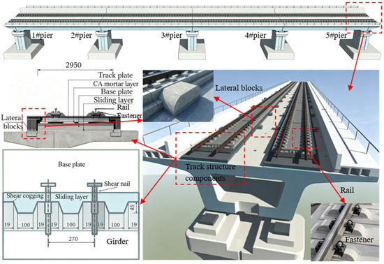
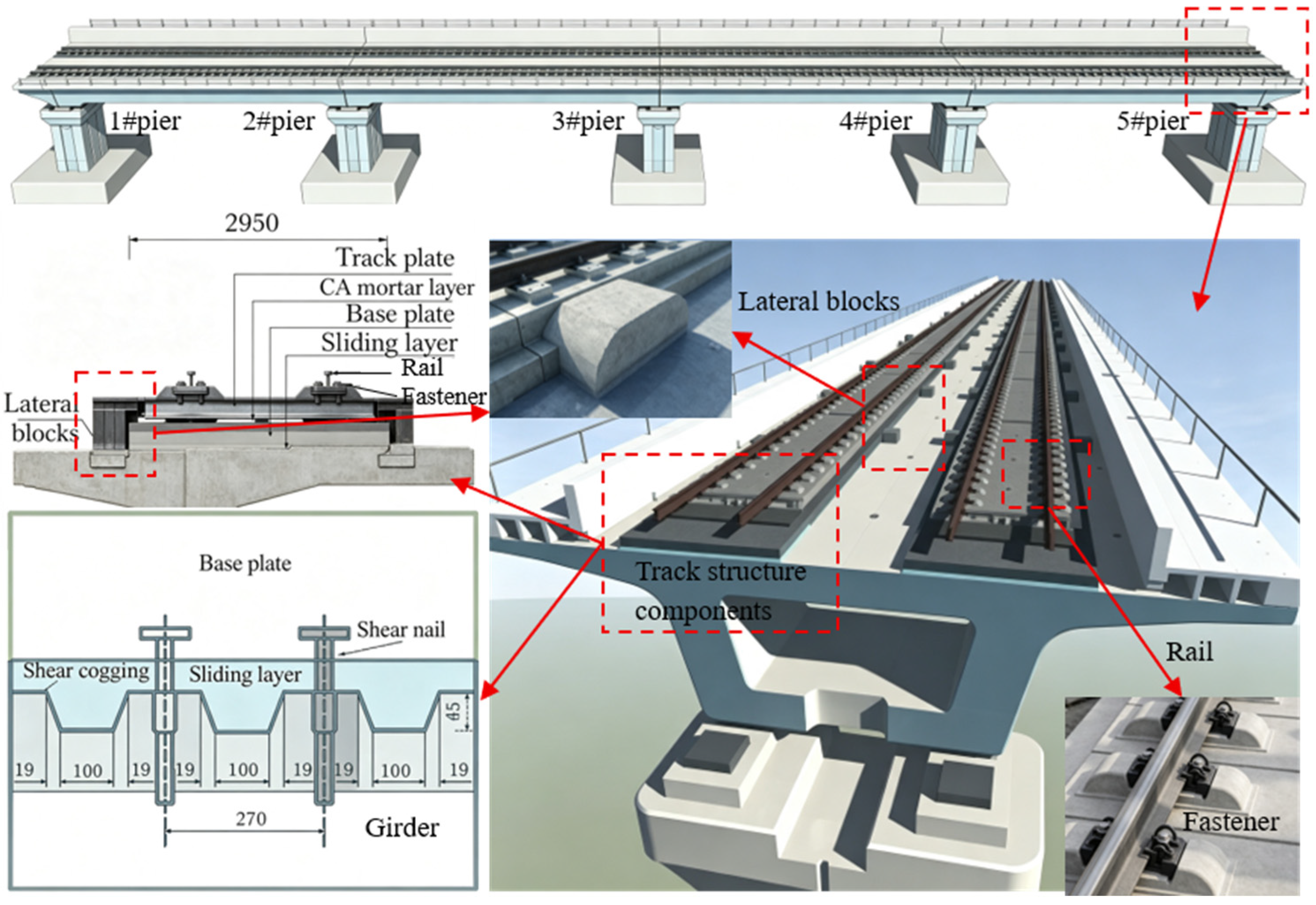
This study takes a typical HSR bridge situated in the near-fault region with seismic fortification intensity VIII as the engineering background. The widely adopted 32 m simply supported box girder bridge coupled with the CRTS II slab track system is selected as the research carrier, as shown in Figure 1. The bridge comprises four simply supported 32 m box girders with uniform single-box single-cell cross-sections. Rectangular solid piers with an identical height of 13.5 m are adopted for the substructure, and the superstructure is equipped with the standard CRTS II slab ballastless track system (Figure 1). The overall structural dimensions, material parameters and component layouts are determined strictly referring to existing practical engineering cases and relevant studies, so as to guarantee the engineering authenticity and generality of the numerical model [21,30,31].
Figure 1.
Schematic of HSRTBS and typical CRTS II track system.
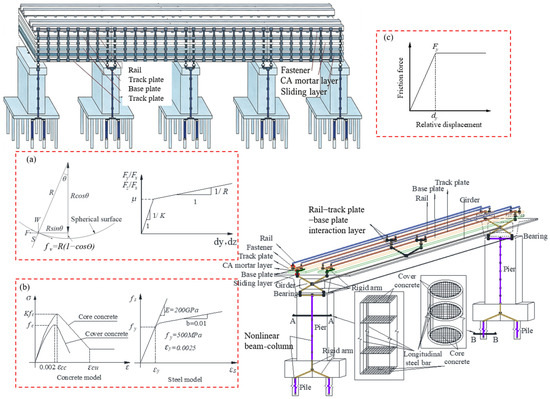
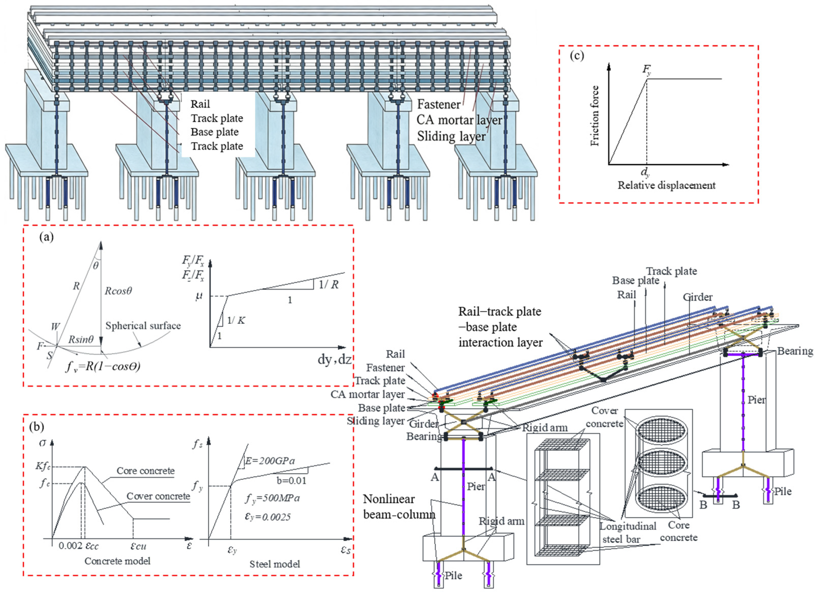
Based on the OpenSEES finite element platform, a refined integrated dynamic numerical model of the HSRTBS is established in this study. To systematically investigate the control effects of isolation measures on seismic deformation and damage responses of the HSRTBS, two comparative models are developed respectively for the common spherical steel bearing system and the friction pendulum bearing (FPB) isolation system. Except for the bearing type, the two models share identical structural dimensions, material parameters, interlayer connection characteristics and boundary conditions, guaranteeing the reliability of comparative analysis on seismic isolation performance. The common model adopts spherical steel bearings, while the FPB isolated model employs friction pendulum bearings, which are refinedly simulated using the built-in SingleFPB element in OpenSEES (v3.8.0), as shown in Figure 2a, with a curvature radius of 3.5 m and a sliding surface friction coefficient of 0.02, accurately capturing the sliding, recentering, and hysteretic energy dissipation behavior of the bearings. For the transient dynamic analysis of beam structures under intense short-duration excitation, advanced analytical calculation frameworks for the rapid characterization of beam dynamic responses have been proposed in the existing literature [35]. Nonlinear time-history integration is performed on OpenSEES in this study to precisely capture the transient dynamic evolution of multi-layer track–bridge systems subjected to earthquakes.
Figure 2.
Finite element modeling of the HSR track–bridge system: (a) SingleFPB element; (b) constitutive models for concrete and reinforcing steel; (c) force–displacement relationship of the zero-length element.
Previous experimental and numerical studies have demonstrated that superstructure components of HSR, including main girders, track slabs and base slabs, exhibit low stress levels and remain in an elastic state without plastic damage under seismic excitation [36]. Therefore, elastic beam elements are adopted to simulate the main girders and rigid track components, with the key sectional and elastic material parameters summarized in Table 1. As the primary energy-dissipating and damage-prone components of the bridge, piers are susceptible to plastic hinges and nonlinear deformation during earthquakes. To accurately reproduce the damage evolution process, piers are finely modeled with fiber beam elements in OpenSEES [13]. The cover concrete and stirrup-confined core concrete are defined using the Concrete 01 constitutive model, and the mechanical parameters of core concrete are modified based on the Kent–Scott–Park theory to account for the improvement of concrete strength and ductility induced by stirrup confinement, as shown in Figure 2b. The longitudinal reinforcements are simulated by the Steel 02 constitutive model, which can effectively characterize the yielding, strain hardening and hysteretic energy dissipation behaviors of steel bars, as shown in Figure 2b. Zero-length nonlinear elements are utilized to simulate the shear-slip mechanical behavior of interlayer components of the CRTS II slab track, including sliding layers, CA mortar layers and fasteners. The corresponding force–displacement relationships and key nonlinear parameters are presented in Figure 2c and Table 2, respectively. To reflect the actual mechanical characteristics, the interlayer components are assigned rigid vertical stiffness, and only the shear nonlinear deformation is activated in the numerical model.
Table 1.
Section parameters of elastic beam elements.
Table 2.
Parameters of zero length connection elements.
2.2. Selection of Ground Motion Records
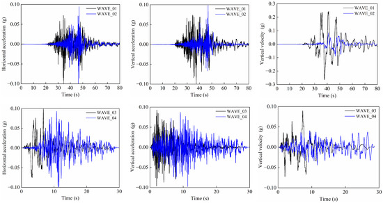
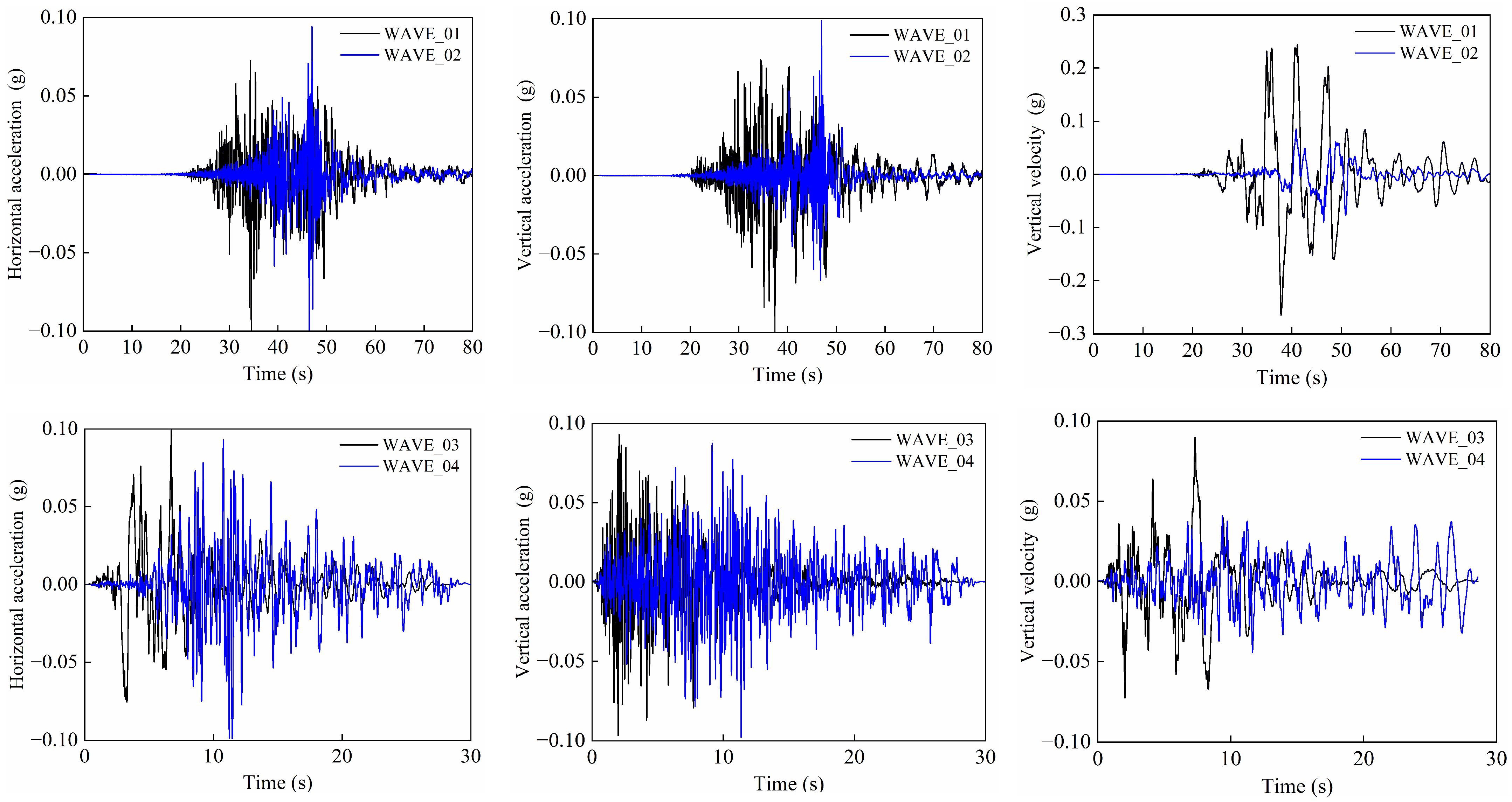
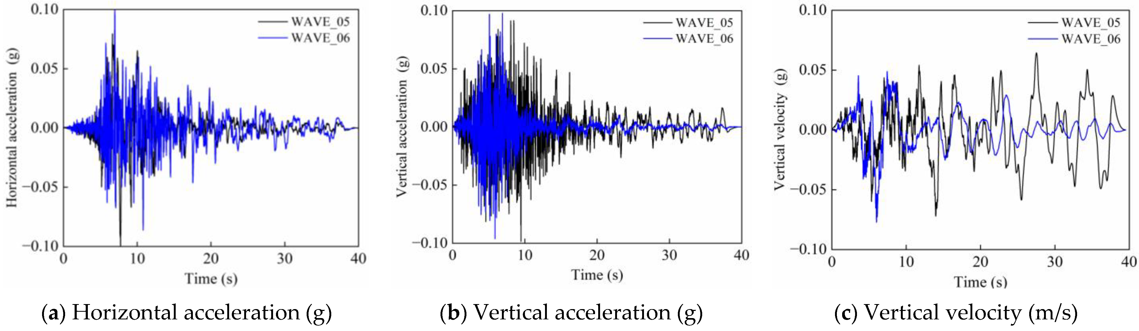
Six typical natural ground motion records are selected from the PEER strong motion database. The standardized screening workflow is specified as follows: Preliminary screening: Raw records with complete horizontal and vertical bidirectional time histories are selected from three major earthquakes (Chi-Chi, Northridge, Imperial Valley). Classification: All candidates are divided into near-fault pulse and far-field non-pulse groups based on calculated peak ground velocity (PGV) to peak ground acceleration (PGA) ratios, pulse period and fault distances. Final selection: One near-fault pulse record and one far-field non-pulse record are chosen from each earthquake event, forming a total of six records. The selected records are distributed differentially in terms of magnitude, fault distance and spectral characteristics to ensure sample representativeness. Detailed fundamental information on the selected ground motions is listed in Table 3. Among these records, WAVE_01, WAVE_03, and WAVE_05 are identified as near-fault pulse-like ground motions with PGV/PGA ratios greater than 0.2. This well-documented classification criterion is validated by Wang et al. [37], and the dimensionless ratio can efficiently distinguish pulse waveforms from ordinary ones. Pulse period (Tp) is another vital indicator for pulse identification; the Tp values of the three near-fault records are summarized in Table 3 to verify their prominent pulse properties. By comparison, WAVE_02, WAVE_04, and WAVE_06 are far-field non-pulse ground motions, forming a reasonable control group for seismic comparison analysis. For each ground motion record, both horizontal and vertical components are simultaneously extracted. The vertical seismic component is quantified by the ratio of vertical to horizontal PGA [38], denoted herein as αVH, and treated as an independent variable. The fundamental parameters, fault distances, magnitudes, and αVH of the original records are summarized in Table 3.
Table 3.
Selected ground motion records and their characteristics.
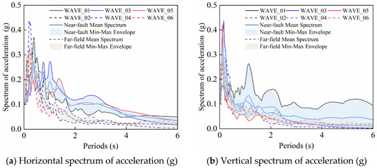
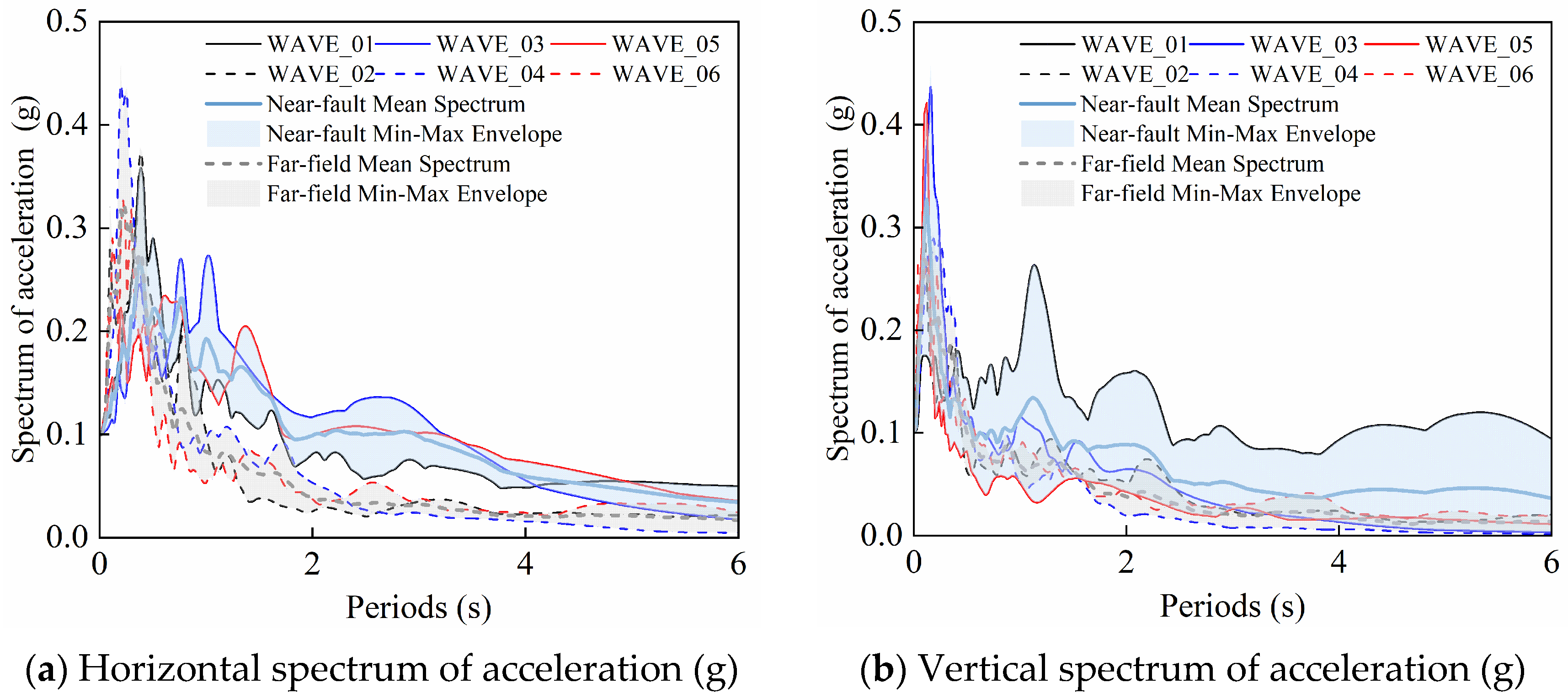
To intuitively illustrate the spectral differences among different ground motions, the horizontal and vertical acceleration time-history curves of the six selected ground motion records are plotted in Figure 3, and the corresponding acceleration response spectra are presented in Figure 4. As can be observed from the time-history curves (Figure 3), WAVE_01, WAVE_03, and WAVE_05 exhibit pronounced pulse characteristics, with seismic energy concentrated and released within a short duration. In contrast, the far-field records WAVE_02, WAVE_04, and WAVE_06 show no obvious pulse features, and the energy distribution along the duration is relatively more uniform. As shown in Figure 4, the six selected ground motions exhibit remarkable inter-group spectral differences. Near-fault pulse-like ground motions maintain high spectral acceleration at medium-to-long periods, while the spectral acceleration of far-field ground motions decays rapidly with increasing period. To represent the random nature of natural earthquakes, records with different magnitudes and fault distances are selected within each group, leading to reasonable dispersion in the response spectra for motions of the same group. Group-mean spectra and shaded min-max envelopes for near-fault and far-field ground motions are superimposed in Figure 4 to visualize such intra-group spectral dispersion. For the far-field ground motions, the spectral values decay more rapidly with increasing period. In addition, each of the selected original records inherently possesses different αVH, which provides the fundamental conditions for conducting parametric analyses of vertical seismic effects.
Figure 3.
Acceleration time-history curves of selected ground motions: (a) Horizontal acceleration (g); (b) vertical acceleration (g); (c) vertical velocity (m/s).
Figure 4.
Acceleration response spectra of selected ground-motion records: (a) Horizontal acceleration; (b) vertical acceleration. Near-fault and far-field group-mean spectra and shaded min-max envelopes are superimposed.
It is worth noting that this study adopts a qualitative parametric comparison framework rather than a quantitative fragility evaluation that requires dozens of ground motion samples. The six selected records originate from three distinct major earthquakes with diverse magnitudes, fault distances, and spectral characteristics, covering three independents near-fault pulse-like and three far-field non-pulse excitations. This design eliminates the bias that may arise from reliance on a single seismic event or recording station, and ensures adequate representativeness to capture the typical dynamic features of the two seismic categories. The observed trends are therefore interpreted as representative patterns rather than statistically robust quantiles; future large-sample fragility analyses with expanded ground motion libraries will be needed to establish probabilistic relationships. Corresponding discussions of this sample-size limitation are also provided in Section 5.
2.3. Calculation Case Setup
Based on the six selected ground motion records, multiple time-history analysis cases are designed, as summarized in Table 4. Adopting a one-factor-at-a-time single-variable control method, this study separately quantifies the individual seismic influence of PGA, αVH, and CA mortar void length on the seismic responses of HSRTBSs and further compares their respective damage magnitudes to reveal the hierarchical control law of each independent factor.
Table 4.
Summary of numerical calculation cases.
For the PGA cases, in accordance with the Chinese seismic design code (GB 50011-2010) [39] and Table 5, Site Class II and Design Earthquake Group 1 are adopted. Four PGA levels of 0.10 g, 0.20 g, 0.30 g, and 0.40 g are obtained through amplitude scaling, corresponding to seismic fortification intensities VII to IX (medium-to-high intensity scenarios) (Table 5). In these cases, αVH = 0 and the CA mortar layer remains intact.
Table 5.
Peak ground acceleration corresponding to different seismic hazard levels under various seismic fortification intensities.
For the αVH cases, with PGA fixed at 0.20 g and the CA mortar layer intact, four αVH ratios of 0, 0.65, 1.00, and 1.50 are established by independently scaling the vertical seismic components, covering both conventional engineering conditions and near-fault high vertical seismic characteristics. It should be acknowledged that this scaling strategy carries certain drawbacks. Horizontal and vertical components of natural ground motions are inherently correlated in terms of waveform, spectrum and peak amplitude, so adjusting vertical signals separately disrupts their original matching characteristics. This single-variable design is nonetheless necessary here, as it enables clear quantification of how vertical excitation magnitude alone affects track–bridge seismic damage and track irregularity. Using unmodified natural records with naturally varying αVH would introduce confounding variables including pulse features and PGA differences, which obscure the pure contribution of vertical seismic loads. For real-world seismic assessment, intact paired horizontal–vertical ground motion records are recommended, whereas the modified wave sets in this work are exclusively prepared for parametric sensitivity investigation.
For the CA mortar void-length cases, continuous separation defects are placed at both ends of each span according to field investigations and existing research, since slab-end voids dominate the seismic response of HSRTBSs [40]. With PGA = 0.20 g and αVH = 0, five void lengths from 0 to 2.60 m are defined at an interval of 0.65 m (consistent with sleeper spacing), covering intact, partial and extensive mortar separation conditions. CA mortar separation is numerically realized by tuning zero-length element properties: all yield force and yield displacement parameters of elements inside void regions are assigned zero to fully cut off interfacial force transfer between track slabs and base plates, whereas intact mortar segments follow the constitutive curve presented in Figure 2c.
For all cases, the horizontal seismic motions are input along the longitudinal direction of the bridge. When αVH > 0, the vertical seismic components are applied simultaneously. All ground motions are input to both the common bearing system (Common Case) and the FPB-isolated track–bridge system (Isolated Case). Nonlinear time-history analyses are conducted to obtain the dynamic response time histories of the two systems, and the peak displacements of key components are extracted as the core response indices. A multi-scale evaluation index system is adopted to assess the seismic performance: pier-top longitudinal displacement is used to evaluate the pier response, bearing shear displacement is adopted to characterize the isolation and energy dissipation effectiveness, and interlayer relative slippage of the track components is employed to reflect the damage states of the track system. By comparing the peak component displacements with the corresponding damage thresholds, the damage distribution proportion along the entire bridge is statistically quantified. Furthermore, based on track vertical deformations, five-level track regularity and traffic safety intervals are defined, enabling an integrated quantitative assessment from component damage and spatial damage distribution to post-earthquake traffic capacity of the line.
2.4. Model Validation
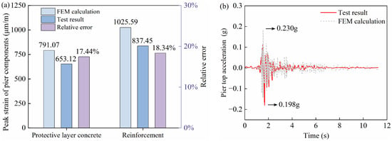
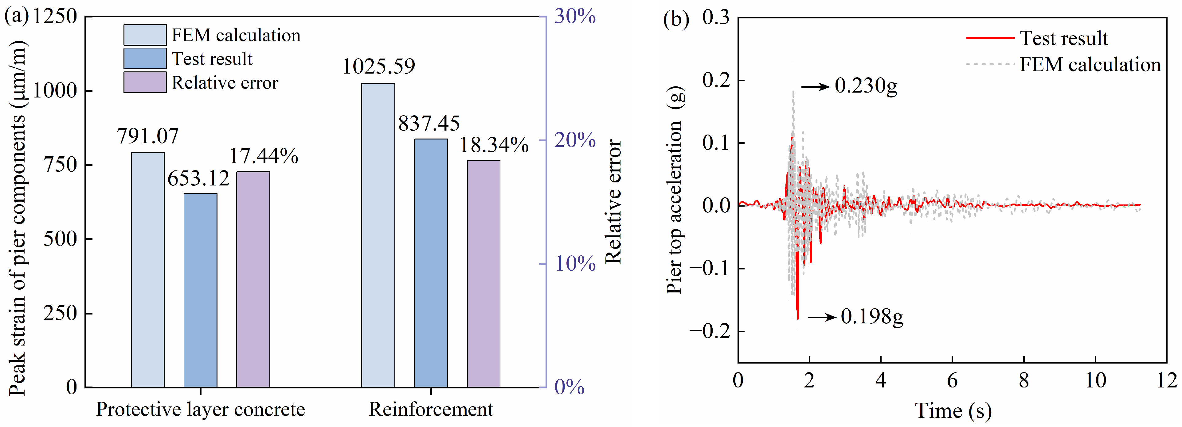
The modeling strategy, element types, material constitutive models, and parameter settings adopted in this study are consistent with those used in the authors’ previous work [21]. Therefore, only a brief description of the validation basis and conclusions is provided here to avoid repetition. Referring to the shaking table test conducted by Hu et al. [41], a finite element model of the prototype structure was re-established using the present modeling approach for validation purposes. The test employed a 1/10 scale three-span simply supported girder bridge subjected to the Imperial Valley wave (RSN170, PGA = 0.235 g). The peak strains of pier cover concrete and longitudinal reinforcement from numerical simulations are compared against experimental measurements in Figure 5a. The pier-top acceleration time-history curves, together with their peak values, are presented in Figure 5b. The predicted peak values marginally exceed the test measurements, and all relative discrepancies are within 20%, which represents an acceptable error range for shaking table test comparisons. The numerical predictions are in good agreement with the experimental responses, confirming that the adopted modeling strategy, element constitutive models, and parameter settings are reasonable, and that the FEM possesses reliable computational accuracy.
Figure 5.
Comparisons between finite element predictions and shaking table test results: (a) peak strains of pier components; (b) pier-top acceleration time-history responses.
Notably, the scaled shaking table test adopted in this study only equivalently considers the track self-weight and fails to reproduce the complete layered structure of the CRTS II ballastless track system. In addition, no monitoring points were arranged for FPBs, CA mortar and track-related deformations in the original test, making it incapable of calibrating track and isolation-level response indicators. Given this objective limitation, the current validation focuses on pier fiber elements, material constitutive laws and the computational framework. Piers are the primary load-carrying components of the HSRTBS, so their accurate simulation underpins the reliability of overall seismic analysis. In bridge seismic numerical research, it is standard to validate the core modeling framework through local structural responses before expanding parametric analysis of other components; full experimental coverage of all research indices is not mandatory [3,13,24]. The track, FPB and CA mortar parameters adopted herein are calibrated from established codes and the published literature with solid constitutive support, which renders the present validation scheme reasonable and guarantees credible parametric analysis results.
3. Results and Discussion
3.1. Analysis of Bridge Structural Response
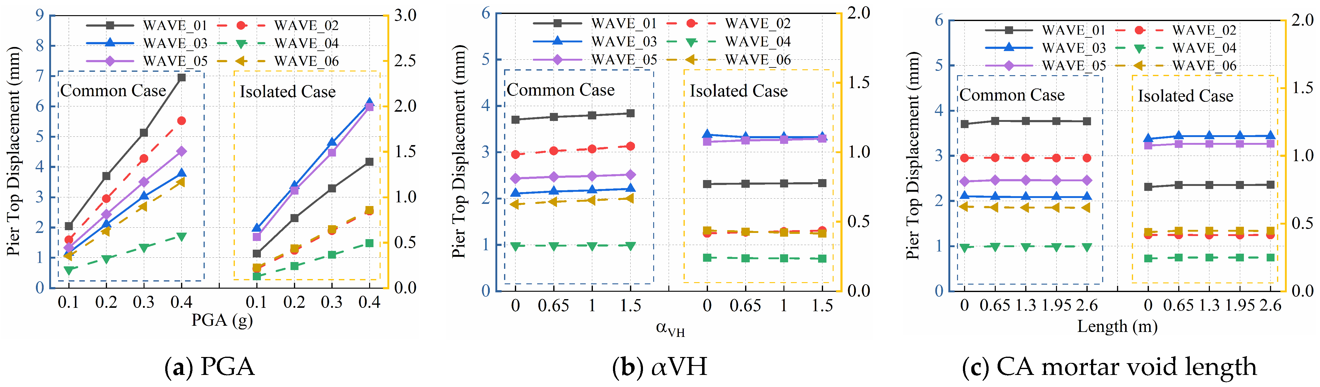
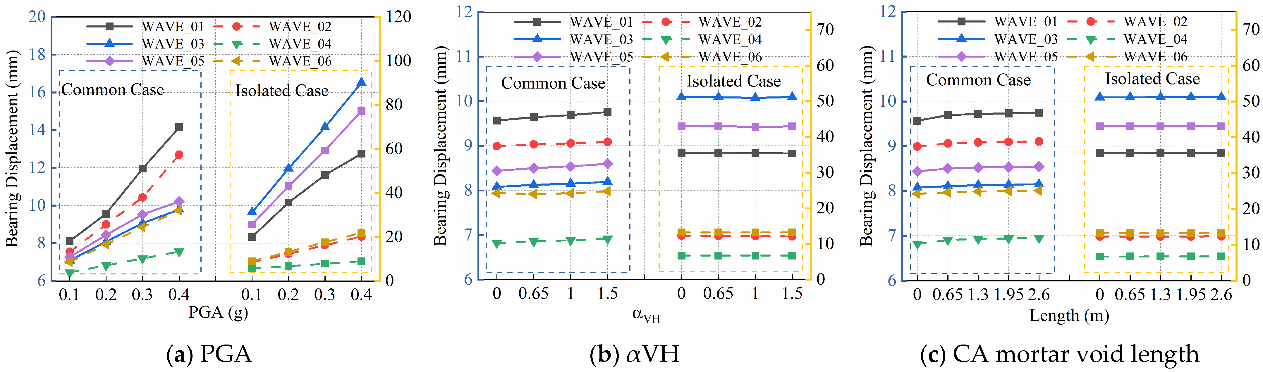
This section focuses on the bridge piers and bearings, systematically investigating the effects of PGA, αVH, and CA mortar void length on the longitudinal peak displacements of piers and bearings. The deformation responses of the Common Case and Isolated Case are comparatively analyzed. Figure 6 presents pier-top displacement responses, and Figure 7 illustrates bearing displacement responses. For clarity, the Common Case results correspond to the left vertical axis, while the Isolated Case results correspond to the right vertical axis.
Figure 6.
Effects of different parameters on pier-top displacement for Common Case and Isolated Case: (a) PGA; (b) αVH; (c) CA mortar void length.
Figure 7.
Effects of different parameters on bearing displacement for Common Case and Isolated Case: (a) PGA; (b) αVH; (c) CA mortar void length.
3.1.1. Pier-Top Displacement
Effect of PGA: Under the Common Case, the longitudinal displacement of the pier top increases approximately linearly with PGA, indicating high sensitivity to seismic intensity. At PGA = 0.4 g, the maximum pier-top displacement under WAVE_01 reaches 7.0 mm. The pier-top displacements induced by near-fault pulse-like ground motions are generally larger than those induced by far-field ground motions, as shown in Figure 6a. The Isolated Case significantly constrains the pier-top deformation; under the same PGA level, the maximum pier-top displacement corresponding to WAVE_05 is only 2.1 mm, corresponding to a reduction rate of 86.73%, and the growth rate of displacement is markedly reduced. The isolation bearings dissipate seismic energy and attenuate the amplifying effect of PGA on pier deformation; however, near-fault pulse-like ground motions still induce relatively unfavorable responses.
Effect of αVH: The pier-top displacement is generally insensitive to variations in αVH. Under the Common Case, the pier-top displacement under WAVE_01 remains between 3.7 mm and 3.84 mm and rises slightly with the increase in αVH. Under the Isolated Case, the maximum displacement under WAVE_05 is basically stable at 1.3 mm, with a reduction rate of 86.08%, as illustrated in Figure 6b. The longitudinal displacement of the pier is mainly governed by the horizontal seismic component, while the vertical component exerts a negligible influence; variations in αVH do not alter the longitudinal force-deformation characteristics of the pier. The isolation system further counteracts the minor deformation increment induced by the vertical component. The displacement responses under near-fault ground motions are consistently larger than those under far-field ground motions, and this pattern remains unchanged with varying αVH.
Effect of CA mortar void length: Within the void-length range of 0–2.6 m, the pier-top displacements under the Common Case and Isolated Case fluctuate slightly, demonstrating that the pier response has extremely low sensitivity to mortar voids, as shown in Figure 6c. Under the Common Case, the maximum displacement under WAVE_01 is approximately 3.7 mm, while the displacement under WAVE_03 in the Isolated Case is around 1.3 mm, presenting a stable isolation performance with a reduction rate of 85.93%. CA mortar mainly undertakes vertical load transfer and possesses low longitudinal stiffness. Local voids only change the local force state of the track and cannot alter the overall seismic resistance system of the bridge pier. Near-fault ground motions consistently trigger larger displacements under all working conditions.
3.1.2. Bearing Displacement
Effect of PGA: As shown in Figure 7a, under the Common Case, the longitudinal displacement of the bearing increases approximately linearly with PGA, indicating high sensitivity to seismic intensity. At PGA = 0.4 g, the maximum bearing displacement reaches 14 mm under WAVE_01. The FPB isolation bearings dissipate seismic energy through horizontal deformation; the maximum displacement under WAVE_03 reaches 90 mm at PGA = 0.4 g, approximately eight times that of the bearings in the Common Case, and structural seismic mitigation is realized through large deformation. Bearing displacements induced by near-fault pulse-type ground motions are significantly larger than those induced by far-field ground motions, with remarkable amplification effects of pulse loads.
Effect of αVH: As illustrated in Figure 7b, the bearing displacement is generally insensitive to variations in αVH. Under the Common Case, the bearing displacement increases slightly with increasing αVH; under the Isolated Case, the bearing displacement is almost unaffected by variations in αVH. The longitudinal deformation of the bearing is mainly governed by the horizontal seismic component, while the vertical component contributes only marginally; the isolation system further attenuates the disturbance from the vertical component. The deformation amplitude of the isolation bearings is approximately five times that of the ordinary bearings, demonstrating a remarkable isolation effect. Both systems exhibit larger bearing displacements under near-fault ground motions, and αVH does not alter the deformation differences induced by different ground motions.
Effect of CA mortar void length: As shown in Figure 7c, within the void-length range of 0–2.6 m, the bearing displacement under the Common Case increases slightly with increasing void length, while that under the Isolated Case remains stable. The CA mortar possesses limited longitudinal restraint capacity; localized voiding only alters the local track state and does not change the core force-deformation mechanism of the bearing, and thus the bearing displacement does not exhibit significant fluctuations. The isolation bearings maintain a stable isolation effect, with displacement amplitudes approximately five times those of the Common Case. Near-fault ground motions consistently induce larger bearing displacements, while far-field ground motions produce relatively milder excitations.
3.2. Analysis of Track Component Displacement
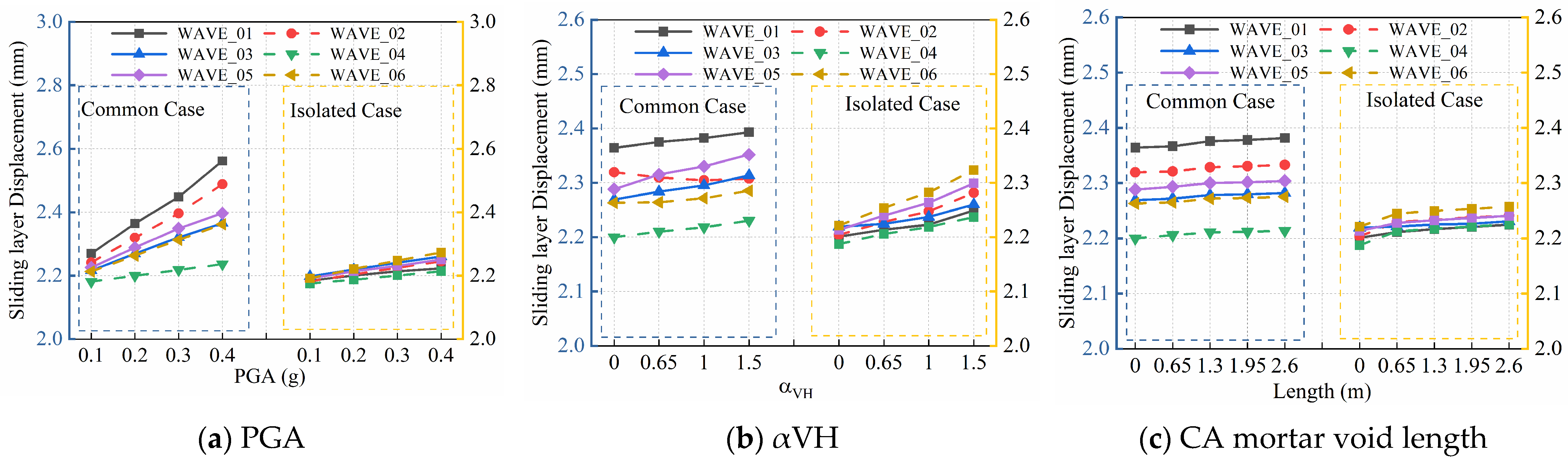
This section takes three typical interlayer components of the track structure, namely the sliding layer, CA mortar layer, and fasteners, and systematically investigates the effects of PGA, αVH, and CA mortar void length on their longitudinal peak displacements. The interlayer deformation characteristics of the Common Case and the Isolated Case are comparatively analyzed, and the corresponding results are presented in Figure 8, Figure 9 and Figure 10, respectively. Since the relative interlayer displacement reaches the maximum at beam gaps, the peak interlayer displacements at these critical sections are extracted for systematic analysis. For clarity, the results of the Common Case correspond to the left vertical axis, while the results of the Isolated Case correspond to the right vertical axis.
Figure 8.
Effects of different parameters on sliding layer displacement for Common Case and Isolated Case: (a) PGA; (b) αVH; (c) CA mortar void length.
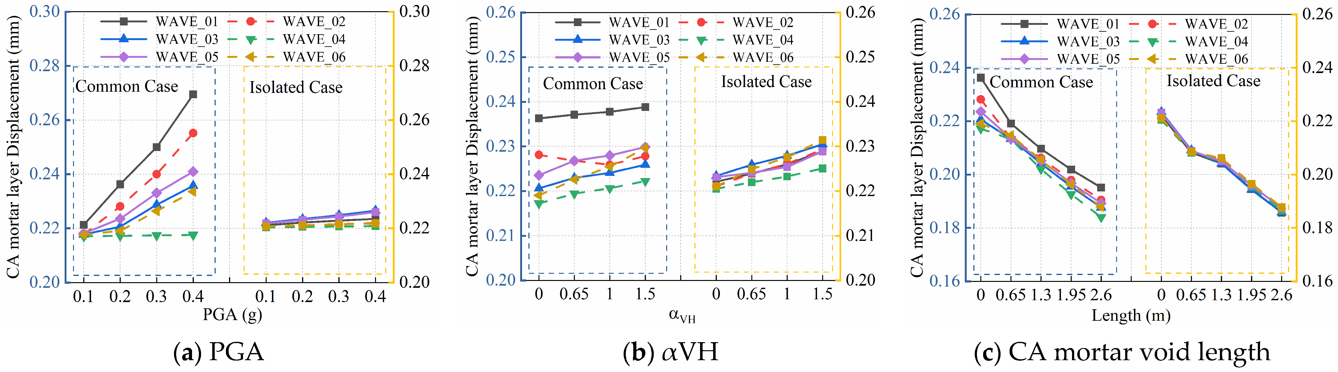
Figure 9.
Effects of different parameters on CA mortar layer displacement for Common Case and Isolated Case: (a) PGA; (b) αVH; (c) CA mortar void length.
Figure 10.
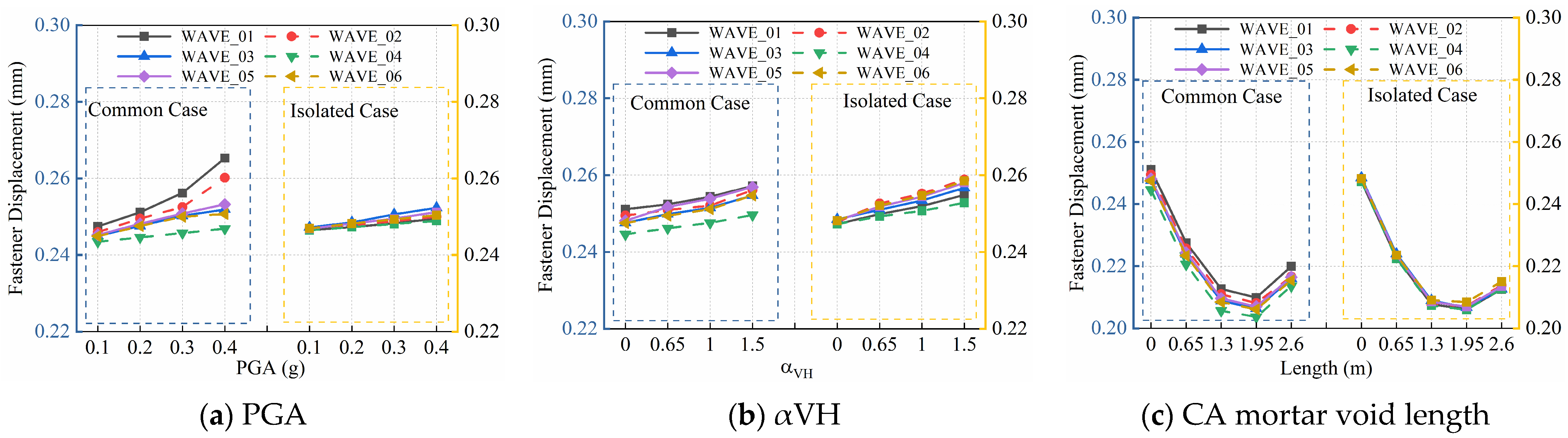
Effects of different parameters on fastener displacement for Common Case and Isolated Case: (a) PGA; (b) αVH; (c) CA mortar void length.
3.2.1. Sliding Layer Displacement
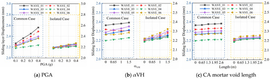
Effect of PGA: As shown in Figure 8a, the sliding layer displacement increases approximately linearly with rising PGA under the Common Case, as the enhanced seismic energy intensifies the relative slip between the track and the bridge. The Isolated Case effectively suppresses the sliding layer displacement, exhibiting lower overall displacement amplitudes and a vibration reduction rate of 13.22%, with a markedly slower displacement growth rate. For both cases, the sliding layer displacement induced by near-fault pulse-like ground motions is significantly larger than that caused by far-field seismic waves, highlighting the greater susceptibility of the system to the high-energy pulse characteristics of near-fault motions. The maximum displacement reaches approximately 2.58 mm under the WAVE_01 record at PGA = 0.4 g in the Common Case.
Effect of αVH: As shown in Figure 8b, the sliding layer displacement is sensitive to variations in αVH. Under both the Common Case and the Isolated Case, the displacement exhibits a clear increasing trend with the growth of αVH. When αVH rises from 0 to 1.5, the displacement increases by approximately 0.9–2.7% for the Common Case and 1.8–4.4% for the Isolated Case. The isolated system maintains smaller overall displacement amplitudes, achieving a vibration reduction rate of 6%. The coupling effect of the vertical and horizontal seismic components amplifies the interlayer relative deformation; the vertical disturbance propagates through the bearing–track system and further exacerbates the sliding layer deformation. The displacement response under near-fault seismic waves remains consistently larger than that under far-field waves. An increase in αVH does not alter this rule but only synchronously amplifies the displacement amplitude for each seismic wave. The maximum displacement is approximately 2.4 mm under the WAVE_01 record at αVH = 1.5 in the Common Case.
Effect of CA mortar void length: As shown in Figure 8c, within the CA mortar void length ranging from 0 to 2.6 m, the sliding layer displacement rises slowly with the increase in void length with an observable increment. The displacement increases by roughly 0.35–0.62% under the Common Case and 0.43–0.59% under the Isolated Case. CA mortar voids weaken the longitudinal constraint of the track structure and aggravate interlayer slip. The deformation of the isolation system remains at a lower level, with the maximum damping rate of 7%. The peak displacement reaches 2.4 mm under WAVE_01 in the Common Case when the void length is 2.6 m. The slip induced by near-fault ground motions remains larger than that induced by far-field ground motions. CA mortar voids cannot change the discrepancy in seismic response and merely amplify the displacement amplitude synchronously.
3.2.2. CA Mortar Layer Displacement
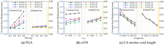
Effect of PGA: As shown in Figure 9a, under the Common Case, the CA mortar layer displacement exhibits a clearly linear increase with rising PGA. The Isolated Case effectively restrains the deformation of the CA mortar layer, achieving a vibration reduction rate of approximately 17.04%, with a markedly slower displacement growth rate. For both cases, the mortar layer deformation induced by near-fault pulse-like ground motions is larger, with displacements significantly higher than those under the corresponding far-field seismic waves, demonstrating a more pronounced influence of the high-energy pulse characteristics of near-fault ground motions. The maximum CA mortar layer displacement reaches approximately 0.27 mm under the WAVE_01 record at PGA = 0.4 g in the Common Case.
Effect of αVH: As shown in Figure 9b, the CA mortar layer displacement is sensitive to variations in αVH. Under both the Common Case and the Isolated Case, the displacement shows a clear increasing trend as αVH increases from 0 to 1.5. The displacement increases by approximately 1.06–4.62% under the Common Case and 2.02–4.46% under the Isolated Case. The overall displacement amplitude is lower than that of the Common Case, with a stable damping rate ranging from 4.15% to 6.01%. Vertical coupled vibration amplifies the shear slip of the mortar layer, and larger seismic responses can be observed under near-fault ground motions.
Effect of CA mortar void length: As shown in Figure 9c, the CA mortar layer displacement decreases significantly with increasing void length. The reduction ranges from 16.59% to 21.10% for Common Case and from 17.73% to 20.17% for Isolated Case. The overall displacement amplitude is smaller compared with the Common Case, and the maximum damping rate reaches 4.99%. The void region withdraws from shear force transmission, leaving only the intact mortar segment to bear the relative displacement. As the effective force-transferring length shortens, the overall slip volume declines. The rule that near-fault ground motions induce larger displacements remains unchanged.
3.2.3. Fastener Displacement
Effect of PGA: As shown in Figure 10a, the fastener displacement increases approximately linearly with rising PGA under the Common Case, indicating a marked sensitivity to variations in seismic intensity. With the increase in input seismic energy, the relative vibration of the HSRTBS intensifies. As the position-limiting component of the track, the longitudinal deformation of fasteners accumulates continuously with seismic energy. The Isolated Case effectively suppresses fastener deformation, achieving a vibration reduction rate of approximately 6%, with a significantly slower displacement growth rate. The fastener deformation induced by near-fault pulse-like ground motions is notably larger than that caused by far-field earthquakes.
Effect of αVH: As illustrated in Figure 10b, fastener displacement is sensitive to variations in αVH. As αVH increases from 0 to 1.5, the displacement presents an obvious upward trend under both the Common Case and the Isolated Case. The displacement rises by approximately 2.01–3.42% under the Common Case and 2.19–4.30% under the Isolated Case, and the overall displacement amplitude is lower than that of the Common Case. The vertical–horizontal coupled vibration amplifies the relative slip between the track and bridge and aggravates the longitudinal deformation of fasteners, resulting in an increase in displacement with the growth of αVH. The displacement response under near-fault earthquakes is consistently greater than that under far-field earthquakes.
Effect of CA mortar void length: As shown in Figure 10c, within the CA mortar void-length range of 0 to 2.6 m, the fastener displacement exhibits a U-shaped variation, first decreasing and then increasing with the growth of the void length. Under the Common Case, the displacement decreases by 19.63–20.08% as the void length extends from 0 to 1.95 m; subsequently, it slightly rebounds by approximately 3.92–4.66% when the void length increases from 1.95 m to 2.6 m. In the early stage of void development (0–1.95 m), the mortar void weakens the local longitudinal constraint, promoting a more uniform redistribution of the relative slip between the track slab and the base, which reduces the local force on the fasteners and thus lowers the displacement. In the later stage (1.95–2.6 m), the remaining intact mortar segment becomes too limited, excessively releasing the longitudinal restraint of the track slab and intensifying the relative vibration between the track and the bridge, thereby causing a slight rebound in fastener displacement. The Isolated Case with FPB exhibits the same response pattern, yet the overall deformation remains lower, with a maximum vibration reduction rate of 3.36%. The fastener displacement induced by near-fault earthquakes is consistently larger.
4. Track–Bridge System Component Damage and Traffic Capacity Assessment
4.1. Classification Criteria
Section 3 reveals the peak displacement response characteristics of various components through parametric analysis. However, relying solely on the full-bridge peak displacement is insufficient to accurately reflect the differences in damage distribution along the bridge span, nor can it directly evaluate the post-earthquake traffic capacity. Therefore, this section establishes a classification framework for spatially distributed damage and track irregularity. Each simply supported beam span is uniformly divided into 50 longitudinal elements. The deformation responses of critical components within each element are extracted and compared with the corresponding damage thresholds. The percentage of section length corresponding to each damage grade relative to the total element length is calculated, and stacked percentage charts are adopted to visually characterize the spatial distribution of damage over the entire bridge. The current Rules for Maintenance of High-speed Railway Ballastless Track Lines (Trial) specify four-grade management limits for track irregularity of HSR, including acceptance standards, routine maintenance standards, temporary repair standards and speed-restriction standards [42]. In this study, rail displacement responses of each component are extracted, and track irregularity grades are classified according to the irregularity thresholds for ballastless tracks under 350 km/h operating conditions [43]. All relevant limit values are summarized in Table 6. The proportions of each irregularity grade interval are then statistically quantified, enabling a quantitative assessment of the traffic capacity of the line under seismic action.
Table 6.
Limit values of track irregularity for HSR tracks [39].
For component damage assessment, with reference to existing research on seismic performance of track–bridge systems, four displacement thresholds, DS1~DS4, are adopted to classify the damage states of primary components of the HSRTBS into five grades: no damage, slight damage, moderate damage, severe damage and complete failure. For superstructure track components (sliding layer, CA mortar layer, fasteners) and bearings, longitudinal relative displacement is taken as the damage criterion, and the corresponding limit values are determined based on experimental results concerning component yielding and sliding failure. The dimensionless drift ratio (pier-top displacement/pier height) is utilized for damage evaluation of bridge piers. The threshold values for DS1 to DS4 are derived from statistical results of quasi-static tests on real bridges with a confidence level of 90% [22,41]. Such literature-derived experimental thresholds are specifically used herein to quantify component-level damage states. Detailed limit values are summarized in Table 7. These four thresholds divide the response range into five intervals, corresponding sequentially to no damage, slight damage, moderate damage, severe damage and complete failure of track interlayer structures.
Table 7.
Damage state threshold indices of HSRTBS components [22,38].
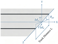
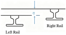
For the evaluation of traffic capacity, given that the seismic inputs considered in this study are longitudinal and vertical ground motions, the lateral response of the rails is extremely small. Both the lateral track irregularity and the cross-level track irregularity (the vertical displacement difference between the two rails on the same line) can therefore be neglected. Accordingly, the vertical displacement of a single rail, namely the vertical profile irregularity, is adopted as the core evaluation indicator. The physical definitions of three typical track irregularity indices are illustrated in Table 8. In accordance with the Rules for Maintenance of High-speed Railway Ballastless Track Lines (Trial), based on vertical track irregularity limits for 350 km/h ballastless tracks shown in Table 6 [42], four thresholds (2 mm, 4 mm, 7 mm, 8 mm) are used to divide the earthquake-induced vertical track irregularity into five safety grades: Intact Smooth Zone (<2 mm), Slight Deviation Zone (2–4 mm), Moderate Deviation Zone (4–7 mm), Severe Warning Zone (7–8 mm), and Critical Speed Restriction Zone (d ≥ 8 mm). It should be noted that these four boundary values originate directly from the official code rather than being self-defined in this paper [42]; the five grade traffic safety intervals are further derived on the basis of these code-specified limits. Each grade corresponds to practical on-site maintenance requirements: the Intact Smooth Zone meets post-maintenance acceptance criteria; the Slight Deviation Zone reaches routine maintenance thresholds; the Moderate Deviation Zone indicates necessary repair treatments; the Severe Warning Zone represents potential safety hazards requiring provisional remediation; and the Critical Speed Restriction Zone matches the engineering trigger for speed limit or track closure operations. Table 9 summarizes these complete classification criteria, and the abbreviated grade labels (Intact, Slight, Moderate, Severe and Critical) are adopted within all subsequent figures.
Table 8.
Definition of track irregularity evaluation indices for HSR tracks.
Table 9.
Classification criteria of track vertical irregularity for traffic capacity assessment.
Comprehensive parametric analyses in Section 3 reveal that under all analyzed cases, the longitudinal deformations of the CA mortar layer and fasteners are consistently lower than their respective minimum damage threshold DS1 (see Table 6, Figure 9 and Figure 10), indicating an Intact state. As critical load-bearing components of the bridge substructure, piers and bearings enter moderate or even severe damage states under certain cases. Nevertheless, their damage is dominated by peak responses at pier tops or bearings, and only the damage states of limited characteristic points can be extracted, making it difficult to characterize their damage via percentage stacked diagrams along the bridge span. Subject to the research focus and length constraints of this paper, spatial distribution analyses for piers and bearings are not carried out in this chapter. In contrast, as a critical weak link in the track structure, the sliding layer readily exceeds the damage threshold in terms of longitudinal deformation, with obviously non-uniform damage distribution along the bridge span, which makes it the core component governing track interlayer slip damage. Meanwhile, the distribution and classification of track vertical irregularity directly determine post-earthquake operation safety. Therefore, the subsequent spatial damage and track irregularity analyses in this section focus on the sliding layer and track vertical irregularity. Percentage stacked diagrams are adopted to elaborate the distribution of damage grades and evolution characteristics of irregularity proportion, providing intuitive support for seismic design and post-earthquake traffic decision-making.
Based on the above classification criteria, this chapter systematically compares the component deformations and spatial damage distributions of the Common Case and Isolated Case, under the effect of PGA, αVH, and CA mortar void length. Parametric analyses of three near-fault and three far-field ground motions have been completed in Section 3, which confirms that WAVE_01 (Chi-Chi, Taiwan, RSN1515) delivers the most remarkable pulse effects and the largest structural response amplitudes, serving as the worst-case controlling excitation. Adopting this critical seismic record facilitates refined quantitative analysis of damage proportions along the full bridge span and eliminates numerous redundant figures that would otherwise result from parallel multi-wave computations and exceed the manuscript page limit. Using this representative worst-case ground motion as input, the subsequent analysis concentrates on how different parameters govern damage evolution, clarifies the damage suppression effectiveness of FPB isolation, and provides recommendations for reasonable values of αVH and void length that balance damage control, thereby offering theoretical support for the integrated seismic design of HSR track–bridge systems.
4.2. Analysis of Sliding Layer Damage and Track Irregularity
4.2.1. Analysis of Sliding Layer Damage
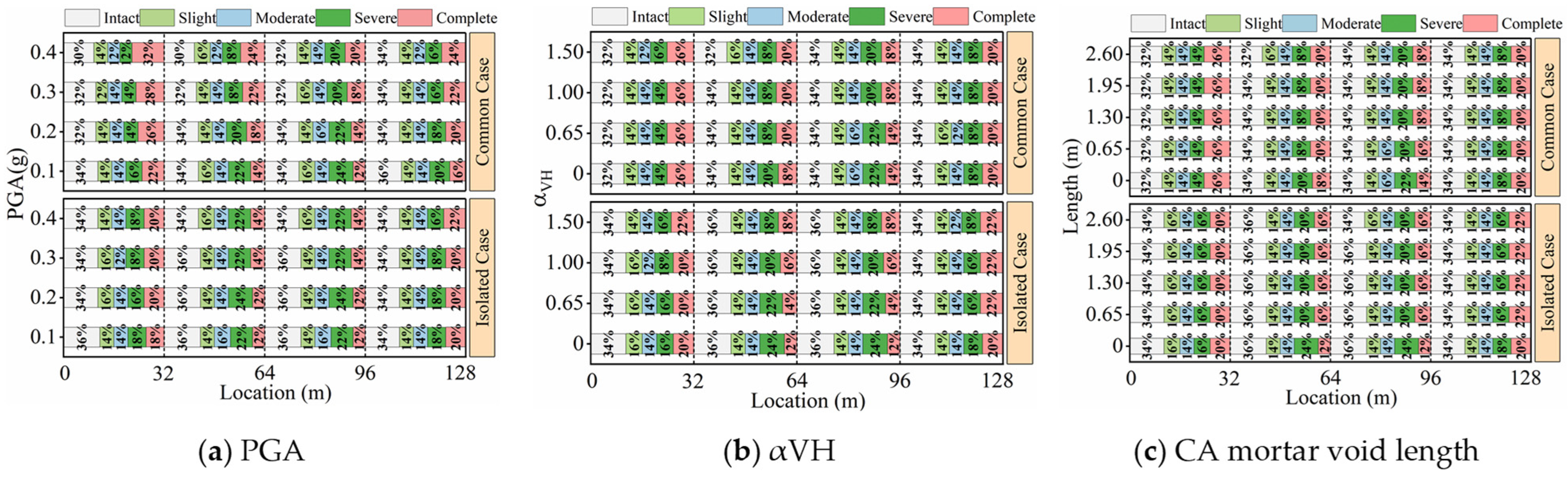
Figure 11a–c present stacked percentage bar charts of sliding layer damage for the four-span 32 m simply supported girder bridge. The damage is classified into five levels: intact, slight, moderate, severe, and complete failure. Comparisons between the Common Case and Isolated Case are carried out to investigate the regulation effects of PGA, αVH, and CA mortar void length on the spatial damage distribution of the sliding layer.
Figure 11.
Distribution law of sliding layer damage of HSRTBS: (a) PGA; (b) αVH; (c) CA mortar void length.
As shown in Figure 11a, with the increase in PGA, the proportion of intact regions of the sliding layer along the entire bridge continuously decreases, while the proportions of severe and complete-failure damage increase significantly. The damage deterioration within the first span (0–32 m) is far more remarkable than that of other spans. Under the Common Case at PGA = 0.4 g, the percentage of complete failure in the first span reaches 32%, making it the most vulnerable segment of the bridge. The FPB isolation can substantially reduce the proportion of high-damage grades in each span. Under the same PGA, the percentage of complete failure in the first span drops to 20%, effectively suppressing the shear debonding damage at the sliding layer interface. Complete failure of the sliding layer releases the longitudinal constraint of the track and triggers considerable longitudinal slip-induced irregularity, aggravating wheel–rail impact. The isolation system can remarkably reduce the proportion of such hazardous damage.
Figure 11b reveals that increasing αVH only slightly raises the proportions of moderate and severe damage, and the growth amplitude of damage is far less than that caused by PGA. Damage develops uniformly across all spans without local aggravation. The FPB isolation mitigates the damage increment caused by coupled vertical–longitudinal vibration, leading to stable variation in the proportions of each damage grade. The vertical seismic coupling effect only slowly exacerbates the sliding layer damage, and its adverse disturbance to running safety remains controllable; isolation can further offset such negative impacts.
It can be observed from Figure 11c that, within the CA mortar void-length range of 0–2.6 m, the proportions of each sliding layer damage grade fluctuate very little, and the proportion of intact regions only decreases slightly. For the Isolated Case, variations in void length barely alter the sliding layer damage distribution. Local CA mortar voids exert a weak influence on interface damage of the sliding layer and longitudinal slip irregularity of the track, and are not the dominant adverse factor affecting seismic running safety.
In summary, first, in terms of damage distribution, PGA serves as the dominant parameter governing the sliding layer failure risk, and the first span is the seismically vulnerable segment of the entire bridge. The disturbance effects of αVH and CA mortar void on sliding layer damage decrease sequentially. Second, the FPB isolation comprehensively reduces the proportions of severe damage and complete failure of the sliding layer along the entire bridge and effectively suppresses interlayer shear deformation. Third, local CA mortar voids have a negligible effect on the evolution of sliding layer damage. It only produces superimposed damage when coupled with high PGA earthquakes, making it unnecessary to separately strengthen the sliding layer solely for this defect.
4.2.2. Analysis of Track Irregularity and Evaluation of Traffic Capacity
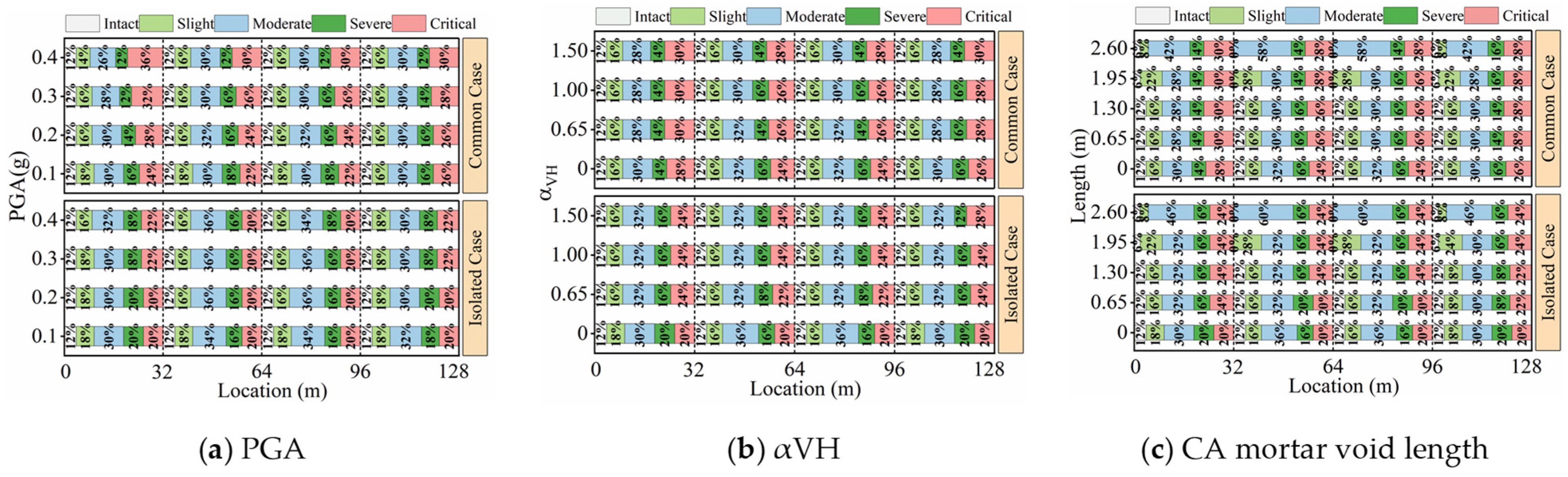
Figure 12a–c illustrate stacked proportion distributions of track vertical irregularity grades for the four-span 32 m simply supported beam bridge under different PGAs, αVH, and CA mortar void lengths. The irregularity grades are classified into five levels: Intact, Slight, Moderate, Severe, and Critical. Comparisons of track regularity are conducted between the Common Case and Isolated Case, and the post-earthquake traffic capacity margin is quantitatively evaluated according to maintenance limits of HSR track irregularity.
Figure 12.
Distribution law of vertical track irregularity in graded proportion of HSRTBS: (a) PGA; (b) αVH; (c) CA mortar void length.
As shown in Figure 12a, PGA is the core seismic parameter controlling the risk of critical vertical track irregularity. With the increase in PGA, under the Common Case, the proportion of the Critical zone along the entire bridge increases significantly, and the deterioration in the first span (0–32 m) is the most pronounced. At PGA = 0.4 g, the Critical proportion in the first span reaches 36%, the track deformation exceeds the speed-restriction threshold, and traffic safety risks increase sharply. After adopting FPB isolation bearings, the proportions of Severe Warning and Critical zones in each span are significantly suppressed. Under the same 0.4 g earthquake, the Critical proportion in the first span drops to 22%, substantially reducing the extreme scenarios that require speed restriction or temporary line closure, and effectively enhancing the safety margin of track regularity under strong earthquakes.
As can be seen from Figure 12b, increasing αVH only slightly increases the proportion of the Critical zone over the entire bridge. The deterioration degree of vertical track irregularity is far lower than that induced by PGA, and the regularity of each span decays slightly and synchronously without obvious local amplification effects among spans. The coupled vertical–longitudinal vibration only slowly amplifies interlayer deformation of the track, which hardly triggers critical irregularities on a large scale and generally cannot lead to full-line closure; thus, it acts as a secondary control indicator for traffic safety. The FPB isolation system can block part of the vertical seismic energy transferring to the upper track and mitigate additional vertical irregularities induced by coupled vibration. As αVH continues to increase, the proportions of Severe Warning and Critical zones tend to stabilize overall, and adverse impacts from vertical seismic motion are effectively alleviated. Integrating the dynamic response and the evolution of track regularity, under the structural configuration, ground motion suite and PGA = 0.20 g seismic intensity adopted in this study, αVH = 0.65 can be adopted as a conditional reference value for corresponding seismic analysis, consistent with the provision of the Code for Seismic Design of Buildings (GB 50011-2010) [39]. This value can reasonably reflect the vertical seismic coupling effect of the investigated HSRTBS within the scope of this research, while avoiding excessively conservative seismic assessment results induced by an excessively large vertical-to-horizontal ratio. This conclusion is not universally applicable to other structural forms or seismic intensities beyond the present study.
Figure 12c reveals that CA mortar voids constitute an independent source of track regularity degradation apart from seismic excitation, which remarkably changes the distribution of vertical irregularity grades and continuously reduces the traffic safety margin. A void length of 1.95 m is a critical threshold for continuous CA mortar defects: when the void length ranges from 0 to 1.95 m, under the Common Case, the proportion of the Intact zone gradually decreases as the void length increases, while the proportion of the Critical zone rises simultaneously. Once the void length exceeds 1.95 m and extends to 2.6 m, the proportion of Moderate irregularity in the two middle spans of the bridge can reach up to 60%, and there are no longer any Intact or Slight regularity segments on the track. Consequently, the wheel–rail system is subjected to persistent abnormal excitation. It should be emphasized that FPB isolation cannot completely eliminate the regularity damage caused by mortar voids. Even with isolation bearings, increasing void length still considerably alters the distribution of irregularity grades, and track deformation and traffic disturbance originating from interfacial debonding defects will be fully manifested. Therefore, for the seismic and traffic safety assessment of isolated HSR bridges, in addition to relying on isolation bearings to improve track performance, the adverse effects of CA mortar void defects should also be considered to comprehensively evaluate track irregularity risks.
In summary, first, the priority order of dominant factors triggering track irregularity risks is: PGA > CA mortar void length > αVH. Second, FPB isolation can effectively mitigate the vertical track irregularity induced by seismic action and reduce the probability of large-scale speed restrictions or line closures under strong earthquakes, whereas its mitigation effect on regularity degradation caused by CA mortar voids is limited. Third, engineering assessment and maintenance recommendations are as follows: (1) Limited to the parametric analysis results obtained solely under the fixed PGA = 0.2 g seismic condition of the present four-span CRTS II track–FPB isolated bridge system, αVH = 0.65 serves only as a conditional reference value for numerical simulation and seismic assessment of identical structural schemes. This value can effectively characterize the vertical–horizontal seismic coupling effect observed in this research. Further increasing αVH to 1.0 and 1.5 only leads to minor structural response differences for the studied model, verifying its representativeness within the scope of our working conditions; this ratio cannot be directly extended to structures with different spans, pier layouts or seismic intensities. (2) The working-condition-dependent critical continuous void threshold of 1.95 m derived in this paper agrees well with the maintenance limit of 1/3 slab length (approximately 2 m) specified in engineering codes [44], which verifies the rationality of existing maintenance standards from the perspective of seismic safety. This value is restricted by various structural and load parameters and only fits the research conditions of this paper; different slab dimensions, void positions, bearings or load cases will lead to different critical void lengths. It is suggested that 1.95 m only acts as a conditional remediation reference under the structural and seismic configurations adopted in this study, and timely grouting repair should be implemented for defects exceeding this threshold. For isolated bridges with extensive CA mortar voids, separate verification of track vertical irregularity is necessary to avoid superimposed traffic risks resulting from the combination of defects and seismic action.
5. Conclusions
This study investigates the proposed track–bridge system, comprising a typical HSR CRTS II slab ballastless track and a 32 m simply supported girder bridge, in near-fault high-seismicity regions. Refined coupled numerical models with spherical steel bearings and friction pendulum bearings (FPBs) are established in OpenSEES. Near-fault pulse-like and far-field non-pulse ground motions are selected to conduct multi-factor nonlinear time-history analyses considering PGA, αVH, and CA mortar void length. The seismic damage mechanisms of the track–bridge system are clarified, and the damage-control effectiveness of FPB is quantitatively defined. The main conclusions are summarized as follows:
- (1)
- Core controlling factors and key mechanisms. PGA acts as the dominant factor governing seismic damage of the track–bridge system. The sensitivity sequence for sliding layer damage follows PGA > αVH > CA mortar void, while the priority of post-earthquake track irregularity risks obeys PGA > CA mortar void > αVH. Under identical seismic intensity, near-fault pulse-like ground motions produce significantly larger structural responses than far-field ground motions and shall be treated as the primary seismic load for near-fault seismic design.
- (2)
- Performance of the FPB isolation system. The FPB achieves a maximum pier-top seismic reduction ratio of 86.73%, effectively restraining pier deformation, interlayer slip, and track irregularity, and significantly reducing the proportion of severe sliding layer damage. However, isolation bearings cannot eliminate the inherent regularity damage caused by CA mortar voids; hence, traffic risks originating from track defects cannot be completely avoided.
- (3)
- Engineering recommendations and design-related references. FPB isolation is recommended for track–bridge structures located in near-fault high seismic intensity zones. Under the PGA = 0.2 g condition, the given bridge configuration and selected ground motions in this study, αVH = 0.65 can be used as a conditional reference for seismic assessment and numerical simulation of comparable track–bridge systems to prevent overly conservative results, though it is not universally valid for all bridge-track layouts or seismic hazard levels. The derived 1.95 m critical CA mortar void threshold for longitudinal track constraint failure agrees well with the industrial code maintenance limit of 1/3 slab length (≈2 m), and is only valid for structures identical to the present model. For FPB-isolated bridges, track irregularity under combined earthquake–void conditions should be independently checked instead of depending solely on isolation bearings.
Limitations: All findings are conditional and restricted to the structural layout, seismic inputs and parameter schemes of this study. Specifically, the conditional reference αVH = 0.65 and the 1.95 m critical void threshold for slab-end continuous voids of the 32 m CRTS II system apply only to the investigated working conditions. Future research will extend structural forms, void patterns and ground motion datasets to improve generalizability. Multi-parameter interaction effects are not analyzed herein and will be explored in follow-up work. With only six ground motion records adopted in this study and only WAVE 01 selected for spatial damage and trafficability quantification in Section 4.2—which cannot fully eliminate seismic randomness—further fragility-based analyses with expanded ground motion libraries are required.
Author Contributions
Conceptualization, H.L. and J.M. (Jianfeng Mao); methodology, H.L.; software, H.L. and J.M. (Jinyu Ma); formal analysis, H.L. and J.M. (Jianfeng Mao); investigation, J.M. (Jinyu Ma); resources, Z.Y.; data curation, H.L. and J.M. (Jinyu Ma).; writing—original draft preparation, H.L.; writing—review and editing, H.L. and J.M. (Jinyu Ma); visualization, J.M. (Jinyu Ma); supervision, Z.Y. and J.M. (Jianfeng Mao); project administration, J.M. (Jianfeng Mao) and H.L.; funding acquisition, H.L. All authors have read and agreed to the published version of the manuscript.
Funding
This research was funded by the National Natural Science Foundation of China (Grant No. 52308517) and the Open Foundation of National Engineering Research Center of High-Speed Railway Construction Technology (Grant No. HSR202107).
Data Availability Statement
The original contributions presented in the study are included in the article. Further inquiries can be directed to the corresponding author.
Conflicts of Interest
The authors declare no conflicts of interest.
Abbreviations
The following abbreviations are used in this manuscript:
| HSR | High-speed railway |
| HSRTBS | High-speed railway track–bridge system |
| PGA | Peak ground acceleration |
| PGV | Peak ground velocity |
| FPB | Friction pendulum bearing |
| αVH | Vertical-to-horizontal acceleration ratio |
| FEM | Finite element model |
| Tp | Pulse period |
References
- Liu, S.; Jiang, L.; Zhou, W.; Yu, J.; Liu, X. Analysis of the influence of CA mortar layer void on the dynamic performance of high-speed trains. Mech. Based Des. Struct. Mech. 2023, 52, 2605–2622. [Google Scholar] [CrossRef] [Scilit]
- Liu, S.; Xu, T.; Jiang, L.Z.; Zhou, W.; Yu, J.; Liu, X.; Ren, Z. Investigating the impact of typical bridge transverse dislocations on the running performance of high-speed trains. J. Vib. Control 2022, 30, 116–129. [Google Scholar] [CrossRef] [Scilit]
- Xiao, B.; Wei, B.; Chen, J.; Zhang, R.; Chen, M.; Zheng, X.; Yang, Z. Damage Control of CRTS III Track-Bridge Systems Using Multi-Component Multi-Level Seismic Design under near-Fault Earthquakes. Adv. Eng. Softw. 2026, 212, 104070. [Google Scholar] [CrossRef] [Scilit]
- Xie, X.; Liu, S.; Zhang, D.; Yang, S.; Chen, D.; Zhou, Z.; Wang, Z.; Wang, Z.; Zhang, X.; Xiang, P. Post-earthquake safety analysis of high-speed trains using velocity-related spectral intensity index considering track irregularities. Mech. Based Des. Struct. Mech. 2025, 54, 2574887. [Google Scholar] [CrossRef] [Scilit]
- He, X.; Wu, T.; Zou, Y.; Chen, Y.F.; Guo, H.; Yu, Z. Recent developments of high-speed railway bridges in China. Struct. Infrastruct. Eng. 2017, 13, 1584–1595. [Google Scholar] [CrossRef] [Scilit]
- Montenegro, P.A.; Carvalho, H.; Ribeiro, D.; Calçada, R.; Tokunaga, M.; Tanabe, M.; Zhai, W. Assessment of train running safety on bridges: A literature review. Eng. Struct. 2021, 241, 112425. [Google Scholar] [CrossRef] [Scilit]
- Papazoglou, A.; Elnashai, A. Analytical and field evidence of the damaging effect of vertical earthquake ground motion. Earthq. Eng. Struct. Dyn. 1996, 25, 1109–1137. [Google Scholar] [CrossRef]
- Billah, M.; Alam, M.S.; Bhuiyan, A. Fragility analysis of retrofitted multicolumn bridge bent subjected to near-fault and far-field ground motion. J. Bridge Eng. 2013, 18, 992–1004. [Google Scholar] [CrossRef] [Scilit]
- Taslimi, A.; Petrone, F.; Pitarka, A. Characteristics of Vertical Ground Motions and Their Effect on the Seismic Response of Bridges in the Near-Field: A State-of-the-Art Review. J. Bridge Eng. 2024, 29, 03124001. [Google Scholar] [CrossRef] [Scilit]
- Li, X.; Dou, H.; Zhu, X. Engineering characteristics of near-fault vertical ground motions and their effect on the seismic response of bridges. Earthq. Eng. Eng. Vib. 2007, 6, 345–350. [Google Scholar] [CrossRef] [Scilit]
- Shaohui, L.; Lizhong, J.; Wangbao, Z.; Jian, Y.; Feng, Y.; Zhenbin, R. Influence of velocity pulse effect on earthquake-induced track irregularities of high-speed railway track–bridge system under near-fault ground motions. Arch. Civ. Mech. Eng. 2024, 24, 70. [Google Scholar] [CrossRef] [Scilit]
- Zhou, T.; Jiang, L.Z.; Liu, X.; Xiang, P.; Lai, Z. Running safety of high-speed railway vehicles on the elastoplastic track-subgrade-bridge system under near-fault pulse-type earthquakes. Eng. Struct. 2023, 280, 115692. [Google Scholar] [CrossRef] [Scilit]
- Xiao, B.; Wei, B.; Zhao, H.; Zheng, X.; Zhang, R.; Chen, J.; Jiang, L. Effect of seismic isolation parameters on component damage and running safety performance of high-speed railway bridge-track system under near-fault earthquakes. Eng. Struct. 2025, 328, 119712. [Google Scholar] [CrossRef] [Scilit]
- Guo, G.; Hao, C.; Du, B. Static and dynamic response characteristics of a ballastless track structure of a high-speed railway bridge with interlayer debonding under temperature loads. Eng. Fail. Anal. 2023, 151, 107377. [Google Scholar] [CrossRef] [Scilit]
- Tao, Y.; Yuan, X.; Zhong, J. Near-fault pulse seismic ductility spectra for bridge columns based on machine learning. Soil Dyn. Earthq. Eng. 2023, 164, 107582. [Google Scholar] [CrossRef] [Scilit]
- Jiang, L.; Zhong, J.; Yuan, W. The pulse effect on the isolation device optimization of simply supported bridges in near-fault regions. Structures 2020, 27, 853–867. [Google Scholar] [CrossRef] [Scilit]
- Guo, W.; Gao, X.; Hu, P.; Hu, Y.; Zhai, Z.; Bu, D.; Jiang, L. Seismic damage features of high-speed railway simply supported bridge–track system under near-fault earthquake. Adv. Struct. Eng. 2020, 23, 1573–1586. [Google Scholar] [CrossRef] [Scilit]
- Shi, Y.; Xiang, G.; Liu, Y.; Zheng, G.; Qin, H. Seismic Response and Damage Analysis of High-speed Railway Continuous Rigid-frame Bridge under Near-fault Ground Motion. Technol. Earthq. Disaster Prev. 2026, 21, 79–94. [Google Scholar] [CrossRef]
- Jiang, L.; Duan, H.; Wen, T.; Jiang, L. Effects of Near-Fault Pulse-Like Ground Motions and Pulse Parameters on a High-Speed Railway Long-Span Arch Bridge–Track System. J. Bridge Eng. 2025, 30, 04024112. [Google Scholar] [CrossRef] [Scilit]
- Guo, W.; Yang, S.; Jiang, L.; Yu, Z.; Zeng, C.; Wang, Y.; Huang, R.; Wu, S.; Ren, S. Effect of near-fault vertical seismic excitation on running safety of trains on high-speed railway bridges. Eng. Struct. 2023, 296, 116880. [Google Scholar] [CrossRef] [Scilit]
- Li, H.; Ma, J.; Yu, Z.; Mao, J. Effects of Near-Fault Vertical Ground Motion on Seismic Response and Damage in High-Speed Railway Isolated Track-Bridge Systems. Buildings 2025, 15, 3320. [Google Scholar] [CrossRef] [Scilit]
- Wei, B.; Zuo, C.; He, X.; Jiang, L.Z.; Wang, T. Effects of vertical ground motions on seismic vulnerabilities of a continuous track-bridge system of high-speed railway. Soil Dyn. Earthq. Eng. 2018, 115, 281–290. [Google Scholar] [CrossRef] [Scilit]
- Shao, Y.; Wei, Y.; Yang, T.; Ni, M.; Zhong, J. Empirical models of bridge seismic fragility surface considering the vertical effect of near-fault ground motions. Structures 2021, 34, 2962–2973. [Google Scholar] [CrossRef] [Scilit]
- Xiao, B.; Biao, W.; Huang, Z.; Zhang, R.; Yang, Z. Research on the seismic damage pattern of the CRTS II track-continuous beam bridge system considering the influence of vertical seismic components. Adv. Eng. Softw. 2026, 218, 104183. [Google Scholar] [CrossRef] [Scilit]
- Liu, S. Study on Seismic-Induced Track Dynamic Irregularities and Post-Seismic Train Running Performance of Type II Ballastless Track-Simply Supported Bridges in High-Speed. Doctoral Dissertation, Central South University, Changsha, China, 2025. [Google Scholar]
- Feng, Y.; Xie, Y.; Wen, S.; Jiang, L.; Chu, J.; Zhou, W. Influence of Mortar Void Length Considering Random Mechanical Parameters on Running Performance. J. Railw. Eng. Soc. 2024, 41, 17–23. [Google Scholar]
- Chen, X. Random Vibration Analysis of Rail-Bridge System Considering Interlayer Damage of CRTS II Ballast Track. Master’s Thesis, Central South University, Changsha, China, 2024. [Google Scholar]
- Yan, B.; Li, Z.; Liu, S.; Xie, H.R. Seismic response of CRTS II ballastless track-bridge system considering the damage of track structure. Sci. Prog. 2021, 104, 00368504211035207. [Google Scholar] [CrossRef] [Scilit] [PubMed]
- Zhou, F.; Tan, P.; Chen, Y.; Liu, Y. Recent Development and Application on Seismic Isolation, Energy Dissipation and Vibration Control in China. In Seismic Isolation, Energy Dissipation and Active Vibration Control of Structures; WCSI 2022; Lecture Notes in Civil Engineering; Springer: Cham, Switzerland, 2023; Volume 309. [Google Scholar]
- Li, H.; Yu, Z.; Mao, J.; Spencer, B.F. Effect of seismic isolation on random seismic response of High-Speed railway bridge based on probability density evolution method. Structures 2021, 29, 1032–1046. [Google Scholar] [CrossRef] [Scilit]
- Li, H.; Yu, Z.; Mao, J.; Jiang, L. Nonlinear random seismic analysis of 3D high-speed railway track-bridge system based on OpenSEES. Structures 2020, 24, 87–98. [Google Scholar] [CrossRef] [Scilit]
- Wei, B.; Yang, Z.; Fu, Y.; Xiao, B.; Jiang, L. Seismic displacement response analysis of Friction Pendulum Bearing under friction coupling and collision effects. Eng. Struct. 2024, 310, 118128. [Google Scholar] [CrossRef] [Scilit]
- Loghman, V.; Khoshnoudian, F.; Banazadeh, M. Effect of vertical component of earthquake on seismic responses of triple concave friction pendulum base-isolated structures. J. Vib. Control 2015, 21, 2099–2113. [Google Scholar] [CrossRef] [Scilit]
- Shao, C.; Xiao, Z.; Qi, Q.; Wei, W.; He, J. Shaking table test on a railway continuous girder bridge with friction pendulum bearings. J. Vib. Shock 2021, 40, 292–298 and 306. [Google Scholar]
- Kafshgarkolaei, H.J.; Lotfollahi-Yaghin, M.A.; Mojtahedi, A. A modified orthonormal polynomial series expansion tailored to thin beams undergoing slamming loads. Ocean Eng. 2019, 182, 38–47. [Google Scholar] [CrossRef] [Scilit]
- Wei, B.; Wang, W.; Wang, P.; Yang, T.; Jiang, L.; Wang, T. Seismic Responses of a High-speed Railway (HSR) Bridge and Track Simulation under Longitudinal Earthquakes. J. Earthq. Eng. 2020, 26, 4449–4470. [Google Scholar] [CrossRef] [Scilit]
- Wang, D.; Liu, B.; Cai, C. The selection principle of near-field horizontal ground motions and characteristics of elastic response spectra for pulse-type horizontal ground motion. Earthq. Eng. Eng. Vib. 2019, 39, 222–230. [Google Scholar]
- Zhong, J.; Zhu, Y.; Han, Q. Impact of vertical ground motion on the statistical analysis of seismic demand for frictional isolated bridge in near-fault regions. Eng. Struct. 2023, 278, 115512. [Google Scholar] [CrossRef] [Scilit]
- GB 50011-2010; Code for Seismic Design of Buildings. China Architecture & Building Press: Beijing, China, 2016.
- Chen, L.; Chen, J.; Wang, J. Study on Stress Transfer and Interface Damage of CRTSII Slab Ballastless Track. J. China Railw. Soc. 2018, 40, 130–138. [Google Scholar]
- Hu, Z. Study on Key Parameters of Seismic Vulnerability and Risk Analysis of High-speed Railway Bridge-Track Structure. Doctoral Dissertation, Central South University, Changsha, China, 2022. [Google Scholar]
- TG/GW 115-2012; Rules for Maintenance of High-speed Railway Ballastless Track Lines (Trial). China Railway Publishing House: Beijing, China, 2012.
- Fan, L. Assessment and Improvement of Post-Seismic Capacity of Railway Girder Bridges. Master’s Thesis, Southwest Jiaotong University, Chengdu, China, 2022. [Google Scholar]
- Xin, X. Research on the Influence and the Identification Method of Mortar Void in High-Speed Railway Track. Doctoral Dissertation, Beijing Jiaotong University, Beijing, China, 2023. [Google Scholar]

Disclaimer/Publisher’s Note: The statements, opinions and data contained in all publications are solely those of the individual author(s) and contributor(s) and not of MDPI and/or the editor(s). MDPI and/or the editor(s) disclaim responsibility for any injury to people or property resulting from any ideas, methods, instructions or products referred to in the content. |
© 2026 by the authors. Licensee MDPI, Basel, Switzerland. This article is an open access article distributed under the terms and conditions of the Creative Commons Attribution (CC BY) license.