


Abstract
The seismic assessment of existing strategic and highly occupied reinforced concrete buildings, such as schools located in moderate-to-high seismic regions, is a critical task, especially because they have been constructed in periods lacking performance-based seismic design requirements. Following a review of possible local and global structural strengthening strategies, this study presents the seismic evaluation and retrofit design of an existing reinforced concrete school building designed before the introduction of modern seismic codes. The assessment is supported by an in situ investigation campaign including destructive and non-destructive materials testing, geotechnical investigations, and a detailed survey of the original construction details. A three-dimensional numerical model, calibrated on the in situ survey and material test results, enables the evaluation of the building’s seismic performance in both the pre- and post-intervention configurations. The model also supports the optimization of retrofit costs: a constraint of relevance because the intervention was funded through a dedicated public budget allocated by the national authority and subject to public validation. This represents a procurement framework that explicitly links the achievable retrofit performance level to a fixed cost ceiling, unlike standard practice in most seismic-prone countries. A global strengthening strategy was implemented including new reinforced concrete shear walls structurally connected to the foundations of the existing walls, whose capacity was enhanced through the installation of micropiles. Fiber-reinforced polymer (FRP) wrapping was applied to improve both flexural and shear beam capacity, while steel jacketing was adopted for some vertical elements. The combined interventions significantly improved the seismic performance of the building, ensuring a safer and more reliable response under future seismic events, respecting the initial publicly available budget.
1. Introduction
The seismic vulnerability of school buildings represents a critical issue in several European countries characterized by moderate-to-high seismic hazard. A large share of the existing school building stock consists of reinforced concrete (RC) structures designed before the enforcement of modern seismic codes, thus lacking adequate detailing, confinement, and ductility capacity [1,2,3,4,5,6,7,8]. Over the past two decades, substantial financial resources have been allocated through national programs, amounting to several billions of euros for seismic mitigation, retrofit, and reconstruction of school facilities [9]. However, structural improvement interventions remain an open issue compared to the scale of the problem [10,11] since existing school buildings require both an adequate load-bearing structural system and secondary elements [12].
Post-earthquake observations have confirmed the high vulnerability of school buildings and the urgent need for large-scale retrofit interventions [10,11,12,13,14,15], mainly due to brittle shear failures in columns, joint damage at beam–column connections, and concentration of plastic deformation in lower stories [16,17,18,19,20]. Moreover, several studies show that their RC frames exhibit limited deformation capacity, reaching significant damage states even under moderate seismic intensity [18,19,20,21].
Also, the response of their non-structural elements should also be assessed with respect to the building’s intended use [22,23].
Similarly, in their seismic evaluation, the variations in the soil’s characteristics should also be considered because groundwater levels may change after some decades in correspondence with the building’s foundation. In fact, soil–structure interaction effects may significantly alter the dynamic response due to variations in the soil stiffness and damping properties [24,25]. Therefore, a wide range of retrofit strategies can be proposed considering that the retrofitting operations must be covered, in most cases, through public funds.
Therefore, the retrofit design of existing RC school buildings is governed by a set of concurrent and often conflicting constraints. First, the extent of element-level deficiencies makes individual element-by-element strengthening impractical and economically unfeasible. Second, the introduction of global stiffening elements (e.g., shear walls, bracing) raises compatibility issues with existing foundations, very often not designed for the resulting concentrated overturning demands. Third, in publicly funded projects, the achievable performance level is directly linked to the allocated budget; this kind of constraint is rarely discussed, but it can lead to implications for the choice of performance target and verification approach. These three issues are those encountered in the case study presented in this paper.
The definition of the retrofit strategy must be conducted on a case-by-case basis, accounting for the specific structural characteristics of the building and for the available budget. Design criteria aimed at seismic improvement or upgrading can be optimized by considering that local interventions [26,27,28] typically provide limited performance gains, on the order of approximately 20%, whereas global interventions including foundation strengthening [21] may achieve improvements up to roughly 50%.
In the presence of a constrained budget, such as in the case study here presented financed by national public funds, it is first necessary to assess the feasibility of introducing new shear walls, evaluating their compatibility with the internal layout, the functional requirements, and the construction feasibility of the associated foundations. If the optimal placement of the shear walls is achievable without substantially altering the architectural and functional configuration of the building, local strengthening measures, for example, using FRP, can then be adopted as complementary actions [29], thereby ensuring an overall optimization of the available budget.
Sometimes other approaches represented by the energy dissipation or the introduction of isolation systems could be considered [30,31]; however, in the case study here presented, dampers and isolators were classified as exceeding the allowable budget due to construction-feasibility constraints identified by the public administration, and were therefore excluded from the decision-making process. They have been considered out of budget, so they have not been considered in the decision-making process.
Considering the above-mentioned points to improve the seismic response of an existing RC school building located in a moderate-to-high seismicity area, this paper is developed as follows: Section 2 reviews the main local retrofit techniques for school buildings, highlighting their respective advantages and limitations. This section provides a systematic discussion of the main local strengthening techniques commonly employed in the seismic upgrading of reinforced concrete buildings, summarizing their respective advantages and limitations based on established literature. It also presents the analytical formulations that can be used to estimate the performance of strengthened members, with reference to European and Italian design standards, as well as to experimentally validated models and practical applications documented in the literature. Emphasis is placed on studies showing similarities with the present case study, including low-ductility frames, columns with low-strength concrete, strengthened members subjected to dynamic (seismic) loading, and interventions on weakly reinforced vertical and horizontal elements and their corresponding beam–column joints. Section 3 discusses the benefits and drawbacks of introducing new shear walls, emphasizing the need to realize and verify the new foundation elements connecting them to the existing ones. Section 4 illustrates a representative school case study (Section 4.1), it includes the investigations on materials and soil’s features (Section 4.2) for the numerical models of the original and retrofitted configurations (Section 4.3) with the structural details of the retrofitted one as well (Section 4.4). In Section 5, the seismic performance improvements (Section 5.1) and the associated economic benefits (Section 5.2) are discussed. Finally, Section 6 summarizes the main conclusions of the study.
2. Local Interventions
2.1. The Use of Fiber-Reinforced Polymer
Fiber-reinforced polymer (FRP) systems are one of the most widely adopted techniques for the seismic retrofit of existing RC structures due to their high strength-to-weight ratio, corrosion resistance, ease of installation, and minimal increase in member dimensions [31,32]. Comprehensive experimental and analytical studies confirm that externally bonded FRP systems (Carbon Fiber-Reinforced Polymer, CFRP; Glass Fiber-Reinforced Polymer, GFRP) are effective in enhancing both the flexural and shear capacity of RC members, as well as improving confinement and ductility of columns [33,34].
Compared to GFRP, CFRP typically provides higher tensile strength and elastic modulus, thus achieving the same target capacity/strain control with lower thickness and better efficiency in confinement and shear strengthening [35,36]; however, it is generally more expensive. GFRP is more cost-effective and therefore attractive for widespread applications, but its lower stiffness may require larger reinforcement ratios to reach comparable performance. Moreover, GFRP may exhibit lower long-term durability than CFRP depending on the environmental exposure and resin system [37].
Ductility and failure mode control may be critical: if anchorage and detailing are inadequate, FRP-strengthened members can fail in a sudden and brittle manner with limited warning, as FRP behaves essentially linear-elastic up to rupture without yielding [38].
The local FRP applications generally refer to existing buildings needed to improve the static and seismic response with minimal invasive techniques [39]. The design of FRP interventions on RC members requires a careful treatment of three interrelated phenomena: material non-linearity of the confined concrete, interfacial fracture mechanics governing debonding, and the strain incompatibility arising from the pre-existing stress state of the original structure at the time of strengthening, which provide a consistent semi-empirical framework to address these issues within a limit-state design format.
For RC vertical elements subjected to axial load, the confinement action due to the continuous FRP jacket increases the compressive strength and the ultimate deformation capacity of the inner concrete part. The model proposed in [40] defines the confined compressive strength fcc as Equation (1) considering the effective lateral confining pressure fl,eff as Equation (2):
where kh is a shape efficiency coefficient that accounts for the progressive reduction in confining effectiveness for non-circular cross-sections, and εfd,rid is the design value of the FRP hoop strain, reduced with respect to the uniaxial tensile rupture strain to reflect the biaxial stress state in the jacket given by Equation (3).
A minimum confinement ratio fl,eff/fck ≥ 0.05 is prescribed as a lower bound for model validity.
fcc = fc · [1 + ψf · 2.6 · (fl,eff/fc)0.9]
fl,eff = kh · ρf · Ef · εfd,rid/2
εfd,rid = 0.45 · εfk/γf.
On the other hand, the flexural capacity of RC beams can be enhanced by bonding FRP laminating the tension face of the beam. The governing failure mode in external fiber reinforcement polymer system typically occurs at the FRP-to-concrete interface at strain levels below the fiber collapse’ strain. Design debonding strain can be expressed by Equation (4) in which ΓFd = is the design interfacial fracture energy given by Equation (5), and kG is a surface preparation coefficient [41].
εfd,e2 = (1/γfd) · [(2 · ΓFd/(Ef · tf)]0.5
ΓFd = kG2 · [(fck · Eck)/γfd]0.5
The design FRP tensile strain is then taken as the minimum between the material collapse limit and εfd,e2.
Moment resistance is computed through strain compatibility, imposing equilibrium between the compression block in the concrete, the tensile force in the steel reinforcement, and the FRP contribution, while enforcing a ductility requirement to ensure a non-brittle failure mode. Attention must be paid to the pre-existing deformation state of the structure, εc0, which reduces the available deformation margin for the FRP laminate.
FRP U-jackets and fully closed wraps are increasingly adopted to supplement the shear capacity of RC beams deficient in transverse reinforcement [42]. The design shear resistance contribution of the FRP system named VRd,f can be expressed by Equation (6) where γRd is the partial factor for the resistance model, 0.9 · d is the effective shear depth (approximated as 90% of the effective flexural depth d), tf is thickness of the FRP laminate (single layer), bf is the width of the FRP strip, sf is the spacing between FRP strips, Ef is elastic modulus of the FRP material, εfd,e is the effective design strain of the FRP, θ is the inclination angle of the principal diagonal crack with respect to the beam axis (typically 45°) accounting for debonding failure, and α is inclination angle of the FRP fibers with respect to the beam axis (90° for vertical strips, 45° for inclined) [39].
VRd,f = (1/γRd) · 0.9 · d · (2 · tf · bf/sf) · Ef · εfd,e · (cot θ + cot α) · sin α
From Equation (6), the effective FRP strain is limited to εfd,e = min(0.95 εfk/γf; 0.004)—where εfk is the characteristic ultimate strain of the FRP material, and γf is the partial safety factor for the fiber composite, typically 1.10, to prevent excessive concrete dilation. For U-jackets, debonding of the laminate from the concrete substrate at the open-end controls εfd,e through a size-dependent reduction factor kv, which depends on the anchorage length le given by Equation (7) and the available bond length with the already mentioned symbols and fck equal to the RC cylindrical resistance.
le = {(Ef · tf)/[2 (fck)0.5]}0.5
An upper bound on the total shear resistance must always be verified against the diagonal strut crushing capacity VRd,max, and the increment attributable to the FRP is subject to the normative limit indicated in Equation (8). In fact, the total shear resistance VRd can be considered as the minimum between: (i) the summation of the shear contribution given by the steel reinforcements (VRd,s) and the fibers (VRd,f), or (ii) the contribution due to the concrete (VRD,c). Equation (8) represents the code limit for the fiber’s contribution.
VRd,f ≤ max{0.50 · VRd,c; 1.30 · VRd,c − VRd,s}
FRP confinement can also significantly improve the cyclic performance by delaying shear failure and bar buckling, thereby transforming brittle failure modes into more ductile flexural mechanisms [43]. An experimental study also demonstrates the effectiveness of FRP systems not only for improving the behavior of existing still undamaged elements, but also for restoring damaged RC members after seismic events in terms of strength recovery and energy dissipation capability [44].
Despite these advantages, some limitations must be considered. A primary issue is the possible premature debonding at the FRP–concrete interface, which can lead to brittle and sudden failure modes and reduce the effective utilization of the composite material [45]. Furthermore, even if the FRP increases the performance of the structural elements locally, its adoption should not significantly increase global stiffness unless used in combination with other strengthening techniques, making them more suitable for local rather than system-level interventions. Therefore, they may be ineffective when the fundamental periods of the structure (associated with a high percentage of the participating mass) intersect the site response spectrum at excessively high acceleration values (e.g., within the spectral plateau).
Another critical limitation concerns ductility and failure mode control: if not properly detailed, FRP-strengthened members may exhibit reduced warning before failure, since FRP materials behave linearly elastic up to rupture without yielding [46].
Also, the economic considerations remain a key constraint in large-scale applications such as school building retrofits because, in most cases, the costs of seismic upgrading and renovation are subject to predefined public budgets. According to [42] FRP strengthening of joints shall primarily aim at: (i) increasing joint shear strength through U-wrap or fully wrapped configurations, (ii) preventing premature debonding through proper anchorage into adjacent beams and columns, and (iii) ensuring that the design strain in FRP is reduced by environmental and bond-dependent efficiency factors. Fundamentally, the use of the only FRP cannot give adequate joint ductility; it becomes effective only when combined with robust confinement (stirrups, jackets, wraps) and rigorously engineered anchorage detailing. FRP wrapping significantly improves joint shear resistance and delays diagonal cracking, but effectiveness is strongly dependent on anchorage length and fiber orientation [47,48]. Also, inadequate detailing may shift damage from the joint core to adjacent beam plastic hinges, limiting the overall benefit of the intervention [49]. Moreover, retrofit interventions should preserve a ductile beam mechanism rather than relocating plastic hinges into brittle joint regions. Consequently, FRP strengthening of joints is often combined with column confinement or beam strengthening to avoid undesirable capacity imbalance [50]. Finally, although FRP strengthening of beam–column joints is effective in improving shear resistance and delaying brittle failure, its contribution to global seismic performance remains local in nature.
2.2. The Concrete Jacketing
Reinforced concrete jacketing is one of the most widely adopted techniques for seismic strengthening of existing RC columns, beams and beam–column nodes. This method allows the simultaneous increase in cross-sectional areas, confinement, axial load capacity, shear resistance, and global stiffness, leading to an enhancement of lateral load-bearing capacity and ductility for the reinforced elements and their nodes. RC jacketing can increase the peak lateral strength of deficient RC frames by more than 50%, while also enhancing stiffness and delaying the onset of localized damage, even if in some configurations these benefits may be accompanied by a reduction in overall deformability, [1]. RC jacketing effectively delays the formation of plastic hinges in columns of RC frames cyclically loaded with a consequent global load redistribution capacity; nevertheless, damage should shift toward beam-end regions due to the strong-column/weak-beam imbalance induced by jacketing [51]. In RC beam–column joints, the cementitious concrete jacketing can locally improve shear resistance transforming the brittle joint shear failure into more ductile beam-controlled mechanisms [52]. Therefore, RC jacketing provides several advantages: high efficiency in strength and stiffness increase due to section enlargement and confinement of the original core concrete; (ii) improved shear resistance and delayed brittle failure modes in the seismic response; (iii) ease of construction thanks to well-known and widely used materials. However, several critical disadvantages and limitations restrict its applicability, particularly in large-scale retrofit programs. In fact, RC jacketing significantly increases the mass and stiffness of the structures, especially when applied to all vertical elements with marked increases in RC section size; consequently, the new enlarged sections can lead to higher seismic inertial forces with possible variations in dynamic features. This effect is particularly critical in irregular-plan buildings, where stiffness redistribution may amplify torsional response [53]. Another negative aspect is the construction invasiveness and downtime, since the RC jacketing requires the removal of the concrete cover, the installation of additional reinforcement bars and the formwork for the casting operations. Therefore, it can imply longer construction periods and incompatibility with continuous building use. It represents a key limitation for facilities such as school buildings. Moreover, since the increase in axial and lateral strength may increase the stress demand on the original foundations, they may not be able to sustain the new demand, leading to potential overloading with local failure mechanisms [54,55]. However, the RC jacketing effectiveness is strongly dependent on interface conditions between old and new concrete: inadequate shear transfer can lead to premature debonding or sliding failure at the interface.
The design of RC jacketing can be carried out according to [12,56] providing adequate confinement of the original concrete core by properly closed transverse stirrups placed at reduced spacing. For a rectangular section, the effectiveness of the transverse reinforcement is quantified through the reinforcement ratios ρsx and ρsy, as defined in Equation (9):
where Ash,x and Ash,y are the areas of the stirrup legs oriented along the - and -directions, respectively; s is the stirrup spacing; and b0 and h0 are the dimensions of the confined core, measured between the stirrup centerlines. The stirrups lead to lateral confining stresses respectively denoted and and expressed by (10).
where fyh is the yield strength of the transverse reinforcement; and αx and αy are the efficiency factors accounting for the non-uniform distribution of confinement [12,56]. Consequently, the average of the previous stresses is the one acting on the core. The jacketing allows the confinement of the original concrete, characterized by its strength denoted fcc,0, which is evaluated by the Mander-type confinement model [57] as in Equation (11).
where fc0 is the unconfined compressive strength of the original concrete; k is a confinement effectiveness coefficient, typically ranging between 3 and 4 for rectangular sections. Moreover, according to [12,56] the design axial resistance of the jacketed section is expressed in Equation (12):
where Ac0 is the area of the original concrete core; Acc is the area of the added concrete jacket; As0 and Asc are respectively the existing and the added longitudinal reinforcement; fcc,0,d is the design strength of the confined original concrete; fcc,d is the design strength of the unconfined jacket concrete; fy,d is the design yield strength of the longitudinal reinforcement; and αc set as 0.85 is the concrete strength reduction factor. The verification under combined axial load and bending follows two key modifications [56]: the original concrete is modeled using a confined stress–strain law; the jacket concrete is modeled using the unconfined stress–strain law. In terms of shear resistance, following [56], the contributions of the concrete or the steel reinforcements, respectively denoted VRd,c and VRd,s, can be considered as in Equations (13) and (14).
where k is a size factor given by k = 1 + (200/d)0.5 ≤ 2; ρl is the longitudinal reinforcement ratio; fck is the characteristic compressive strength of concrete; γc is the safety coefficient for the concrete (set to 1.5); σcp is the average compression stress in the section (given by the ratio between the axial force and the cross-section resistance area); d is the effective height of the section; bw is the section’s width; νmin is given by the relation νmin = 0.035 k3/2 fck1/2 (with the previous symbols); Asw is the shear reinforcement’s cross-section area; s is the spacing between the stirrups; fyd is the design yield strength of steel; θ is the angle of the concrete compression struts in the truss model; and α is the angle of the steel ties in the truss model.
ρsx = Ash,x/(s · b0); ρsy = Ash,y/(s · h0)
flx = αx · ρsx · fyh; fly = αy · ρsy fyh
fcc,0 = fc0 [1 + (k · (f1/fc0)]
NRd = αc · fcc,0,d · Ac0 + αc · fcc,d · Acc + fyd (As0 + Asc)
VRd,c = max{[0.18 · k · (100 · ρl · fck)1/3/γc + 0.15 · σcp] · bw · d; (νmin + 0.15 · σcp) · bw · d}
VRd,s = 0.9 · d · (Asw/s) · fyd (ctgα+ ctgθ) · sinα
3. Global Interventions
3.1. The Introduction of New Shear Walls
The addition of reinforced concrete (RC) shear walls can be recognized as one of the most effective global retrofit strategies for existing reinforced concrete frame buildings [58], including school structures, due to their ability to provide global stiffness redistribution, improving global stability and reducing inter-story drift [50]. Recent experimental evidence confirms that partial or full infill shear wall systems can effectively mitigate soft-story mechanisms and substantially enhance energy dissipation capacity in deficient RC frames [58]. The absence of shear walls in many existing RC buildings can be attributed to historical design practices in which neither a rigorous hierarchy of structural resistance nor an adequate consideration of deformation capacity was systematically ensured [21]. In such contexts, the introduction of shear walls can significantly modify the structural response, but at the same time, they may lead to undesirable concentration of damage if not properly integrated within the existing load-resisting system [59], especially in asymmetric layouts. Consequently, the new shear walls can substantially reduce global drift demands and increase lateral strength, but contemporarily they may induce force redistribution among adjacent unreinforced frame elements, potentially activating new local failure mechanisms. The design of reinforced concrete shear walls is governed by [60] and by [56], addressing design criteria and ductile detailing of seismic walls in medium or high (also briefly named DCM-DCH) ductility classes.
3.2. The New Foundation System
Another issue to consider for the new shear walls in the retrofit of existing RC buildings is their compatibility with the pre-existing foundations [55,61,62]. The effectiveness of lateral-force-resisting systems as the shear walls depends on the safe load transfer mechanisms to the RC foundation, often originally designed for gravity loads. Consequently, the foundation should be inadequate to resist the increased overturning moments and shear forces introduced by the new walls.
The structural response of the foundation should be improved; it should be possible only after the investigation of the soil’s characteristics. The critical influence of foundation flexibility and soil–structure interaction is often underscored, demonstrating that the omission of foundation compliance can yield non-conservative predictions of stiffness enhancement and drift mitigation following retrofit interventions [63]. The incompatibility between new shear walls stiffness and flexible existing foundations may trigger stress concentrations and torsional effects, potentially transferring damage to adjacent members. Common required foundations upgrading includes footing enlargement, addition of new foundation beams, micropiles, or complete reconstruction of local foundation zones to guarantee adequate load transfer. Many issues must be considered. The footings of added walls are typically small and weakly connected to the existing foundation system, leading to uplift and rocking behavior under seismic loading [64].
Moreover, in the cyclic performance of the walls including the force transfer mechanisms to the base, the dependency of stiffness and deformation capacity on the connection between new and existing concrete members is discussed in relation to foundation demand. Often, the adoption of micropiles in the new foundation is mandatory for the features founded in the geotechnical study of the site, even if the original foundation systems do not provide them. Under an economic point of view, the micropile-based foundation retrofits can be influenced by the design assumptions adopted for the pile–foundation connection [65]. The design of new foundation systems required by the introduction of RC shear walls in existing buildings must comply with a multi-layered regulatory framework encompassing geotechnical, structural, and seismic provisions. At the geotechnical level, the governing principles for raft foundations and pile systems are defined in [66].
Where soil conditions or existing foundation constraints preclude a raft solution, micropile systems constitute the primary alternative.
The connection between new and existing foundation elements represents the most critical and normatively demanding aspect of the intervention. Shear transfer at the construction joint between new concrete and the existing foundation is governed by [60], which provides the design model for interfaces cast at different times, accounting for surface roughness and transverse reinforcement. Post-installed rebars and chemical anchors ensuring continuity between the new wall base and the existing footing must comply with [60], which defines verification procedures under tension, shear, and combined actions; for the bonded anchor systems, [67,68] can also be considered.
From a seismic perspective, capacity-design principles require that the full flexural and shear demand at the wall base be reliably transferred to the foundation without brittle failure at the interface.
4. Case Study
4.1. Description
The different techniques discussed in the previous sections are applied to a real case study represented by a high school located in a central Italian region of moderate-to-high seismicity, several times hit by earthquakes (especially in the 1997 and 2016). The school is characterized by five blocks independent of each other. The case study here considered is named Block A. It was designed and built respectively in 1964 and 1966. From a structural point of view, Block A is afflicted by the typical deficiencies of RC buildings of its generation: absence of seismic detailing and the lack of confinement in the critical zones of beams and columns, low-quality concrete, and plain smooth-bar reinforcement with relatively low yield strength.
Block A is a two-story structure with a V-shaped open plan measuring approximately 23.35 × 9.00 m, with classes, aisles and sanitary facilities also present on both floors, (Figure 1).
Figure 1.
Pre-retrofitting intervention. 3D view of the school complex with Block A highlighted in red (a); floor plan of the building (b); a building section (c). Note: the classrooms and the aisles are divided by partitions.
The building rests on deep foundations with pile-cap footings, while the superstructure consists of a cast-in-place RC frame. Column cross-sections vary from 25 × 25 cm to 30 × 40 cm; beam cross-sections are typically 25 × 50 cm to 30 × 60 cm. Floors and roof use SAP-type reinforced hollow-block slabs typical of the construction period [69], with different thicknesses of 16 cm, 20 cm, and 25 cm, spanning predominantly in one direction. Staircase elements include cantilevered landings.
The existing foundation system consists of reinforced concrete pile caps resting on bored piles with a nominal diameter of 400 mm. Pile lengths vary from 4 m to 12 m depending on the depth to competent bearing strata, reflecting the sloping terrain on which the school is sited. Each pile cap is typically supported by one or two piles. This kind of foundation was adopted at the time of original construction due to the presence of loose fill and colluvial material in the upper soil profile.
From the on-site surveys and the partial original drawings, the presence of double-leaf cavity masonry infill walls on the perimeter (12 cm outer leaf of semi-solid bricks + 8 cm inner leaf of hollow-core bricks) was confirmed.
4.2. Materials and Soils Tests
Materials tests have been performed. Regarding the concrete, destructive tests on fifteen cylindrical extracted samples have given different results testifying to a marked difference in concrete quality from the first floor (average resistance of 19.29 MPa) to the second one (10.08 MPa). Consequently, in the finite element model (FEM) the adopted RC classes have been prudentially reduced to C12/15 and C8/10. Regarding the reinforcement steel rebars, tensile tests have given results consistent with the Aq.42 steel specification prescribed in the original project. In the FEM and verifications, the yielding resistance of the steel rebars has been set at fy = 230 N/mm2 [70]. Based on the availability of complete original design drawings, on-site geometry verification, detailed pachometric tests (covering at least 15% of all structural members) and the material tests above mentioned, “Extensive Knowledge” has been reached [71].
Regarding the soil, the building is located at an elevation of approximately 405 m a.s.l. (WGS84: 43°03′53″ N, 12°37′30″ E). The site can be classified as ground type C (360 m/s < Vs, 30 < 800 m/s) with topographic category T2 (slope inclination > 15°), in accordance with the [12]. The subsoil profile is schematized in Figure 2. In the analysis two main layers have been considered according to the geotechnical report available. An upper layer with a 1.00 m thickness characterized by colluvial slope deposits (clays and silts with gravel and sand), with unit weight γ = 18.5 kN/m3, liquid limit wL = 63–100%, plasticity index IP = 35–60%, consistency index IC = 0.96–1.07, drained cohesion c′ = 11–14 kN/m2, friction angle φ′ = 22°, and oedometric modulus Eed = 10,000–20,000 kN/m2. The classification of the first upper layer is A-7-6 by [72], indicating a high-plasticity, potentially compressible material. The second underlying bedrock layer up to −13.00 m consists of compact sandstones with granular structure, interbedded with marls, clayey marls, and calcareous marls—using the previous symbols—with γ = 22.0 kN/m3, IC = 1.1–1.3, c′ = 3–13 kN/m2, and φ′ = 28°.
Figure 2.
Stratigraphy of the soils. Note: Layer 1 and Layer 2 are considered for structural analyses.
4.3. Numerical Models
A full three-dimensional finite element model of the RC frames with decks and original walls was initially developed. It represents the school in the pre-retrofitting case. The structural members (columns, beams, staircase elements) are modeled as beam–column elements. Floor slabs are treated as rigid diaphragms. Original walls have been introduced as bidimensional plate elements. Masonry infill walls have not been relied upon for resistance, but their mass has been included in the seismic analyses. In the pre-intervention model, the original pile foundations are present too. The piles have been modeled as beam-type structural elements interacting with the superstructure, allowing both single-pile and pile-group analysis. Soil–structure interaction has been introduced through stiffness parameters representing: lateral friction, end-bearing resistance, and horizontal stiffness [73]. Lateral response has been computed using the Matlock–Reese formulation [74,75], where each pile is discretized into beam segments embedded in a Winkler medium. The lateral soil reaction has been represented by depth-dependent Kh springs. The resulting soil reactions are automatically integrated by the software along the pile shaft to obtain the equivalent stiffness matrix at the pile head. The vertical resistance from shaft friction has been evaluated based on the geotechnical stratigraphy. For cohesive soils, the undrained shear strength named cu was used within the -method, whereas for granular soils the drained -method was adopted as well, relying on effective vertical stress, horizontal earth-pressure coefficient Ks, and interface friction angle [76]. The computed ultimate shaft resistance has been converted into distributed axial springs assigned to each pile segment in the numerical model. Regarding the end-bearing resistance, the vertical stiffness at the pile tip is governed by the geotechnical bearing-capacity formulation, expressed through the usual factors Nc, Nq and Nγ associated with the soil properties at the pile base [76]. In the finite-element model, this resistance has been represented by a single vertical spring located at the bottom node of the pile, providing the concentrated axial stiffness required to simulate tip-bearing behavior.
The geometries of the foundations and the in-elevation structures reproduce the original drawings already confirmed during the on-site geometrical relief.
The finite element model of the retrofitted configuration keeps the original geometry, but new RC walls have been implemented with the related elements of the foundation system. In fact, the addition of new shear walls introduced in the post-intervention model by bidimensional elements has required the design of new foundation elements, consequently they have been implemented in the retrofitted finite element model with the pre-existing ones for structurally verifying both. The implementation of the new piles in the retrofitted model has been carried out by following the above-mentioned criteria observed for the pre-existing piles.
In both models (pre-existing situation and retrofitted configuration), the dead and live loads are in accordance with the finishes and plants of the architectural project, the intended use of the building and the zone’s snow features. The geometric non-linearity has been considered in the analysis. The response spectrum analysis has been performed in the first non-retrofitted case and in the retrofitted one in accordance with [12], referring to a return period of TR = 475 years and the design peak ground acceleration of PGAD = 2.64 m/s2. The horizontal response spectrum is constructed from the site-specific hazard parameters with soil amplification factors appropriate to the local subsoil class.
In the model representing the pre-existing situation, the behavior factor q of the building was set to q = 3.00 for the horizontal seismic action and q = 1.5 for the vertical one. However, in the model representing the retrofitted configuration, the behavior factor q = 1.5 has been adopted for both vertical and horizontal earthquakes [12]. The horizontal and vertical site spectra are shown in Figure 3. The finite element models of the original configuration and the retrofitted one are shown in Figure 4.
Figure 3.
Horizontal (a) and vertical (b) site spectrum adopted for the seismic analyses.
Figure 4.
Finite element model of the original configuration (a,c,e,g) and the retrofitted configuration (b,d,f,h).
The verifications in the original configuration and in the retrofitted one have been performed by distinguishing the following failure modes: (i) ductile/strength, ruled by shear demand exceeding the flexural-mechanism shear capacity; (ii) ductile/rotation, governed by chord rotation at the ultimate limit state; (iii) brittle, where shear failure precedes flexural capacity; and (iv) brittle joint, where shear failure occurs in the beam–column panel zone brittle, when shear failure precedes the attainment of the flexural capacity of the member, and ductile, for elements exhibiting flexural failure with sufficient deformation capacity. The resulting capacity estimates are inevitably affected by epistemic uncertainties related to as-built material variability and the simplified soil–structure interaction.
Referring to the original configuration, Figure 5 shows the beam elements not satisfying the seismic design demand, in terms of shear (brittle mechanism) and combined axial force and bending (ductile mechanism). The brittle verifications are expressed in terms of the shear action, as the ratio VSD/VRD between the acting shear (VSD) and the design shear resistance (VRD), evaluated under the most critical load combination. The ductile verifications are expressed through the PGA capacity (PGAC) at which the element reaches its chord rotation limit, normalized with respect to the design demand (PGAD) as explained as well in Section 5.
Figure 5.
Elements not satisfying the seismic design demand in the original configuration. (a) On the left, in solid yellow, elements failing in shear, brittle mechanism. (b) On the right, in solid red, elements failing in combined axial force and bending, ductile mechanism.
4.4. Structural Interventions in the Retrofitted Configuration
The retrofit intervention is mainly based on the introduction of new RC shear walls (C25/30 resistance class) provided with new piled foundations connected to the existing ones. The new walls have been positioned according to the original architectural layout of the building, in correspondence with the positions originally occupied by classroom partition walls, in the aisles, and on the perimeter of the lateral stairs. To provide a box-like structural response, in the classroom zone the floors have been strengthened in their plane and properly connected to the new RC walls. In fact, a Glass Fiber-Reinforced layer combined with a fiber-reinforced screed placed above the original slabs has been adopted, while the connections between the new layers and the perimeter RC elements have been realized using conventional bent reinforcing steel bars. In the following, Figure 6 shows the positions of the new walls, Figure 7 shows the common details of the new (named) A-H walls at their ends (Figure 7a) and in their central branches (Figure 7b), and Figure 8 shows the jacketing of existing partitions in the classrooms (Wall F and Wall H on the second floor). Figure 9 represents an execution phase of the realization of the new RC walls.
Figure 6.
Retrofitted configuration: representation of the new shear walls on the first floor (a) and on the second floor (b). Note: in green, the ends of the new walls; in blue, the central part of the new walls; in red, the existing partitions included in the new walls; and in dashed green, the existing partition to be maintained in a second floor classroom. The new RC walls are named A-H. The central and end parts of the RC walls differ in terms of the number of the transverse connectors between the sides of the walls (n.°12/m2 and n.°9/m2).
Figure 7.
Retrofitted configuration: section view of the common reinforcements present at the ends (a) and in the central parts of the new RC walls in the classrooms’ zone (b). Dimensions expressed in cm, quotes indicated in m.
Figure 8.
Retrofitted configuration: section view of the RC jacketing for existing partitions on the first floor. Dimensions expressed in cm, quotes indicated in m and the symbol # represents the number of the stirrups’arms.
Figure 9.
Execution phase of the new RC wall.
Finally, Figure 10 details the reinforcements of the decks in the classrooms and aisle zones. The design of the new RC shear elements and the RC jacketing has been carried out considering the previous Equations (9)–(11) for the confinement and the previous Equations (12)–(14) in terms of resistance effects. Moreover, Equation (8) was adopted for the in-plane shear resistance of the reinforced deck.
Figure 10.
Retrofitted configuration: section of the deck’s reinforcement in the classrooms.
The introduction of the shear walls decreases the fundamental period of the structure from 0.37 s of the original configuration to 0.29 s of the retrofitted one; however, the new RC walls give higher lateral stiffness with respect to the original configuration. Since the period of the retrofitted configuration remains in correspondence with the plateau of the spectrum characterized by dimensionless acceleration (ag/g) of 0.26 in the period range of 0.16–0.48 s, the new RC walls and the jacketing are an improvement in terms of seismic response.
Attention has been devoted to the interaction between the new and the existing foundation systems, as is shown in Figure 11, where the new foundation elements are represented in red, and in Figure 12, where the connection details between the pre-existing and the new foundation elements are represented. Figure 12 represents the section named A-A in Figure 11. Moreover, Figure 13 shows the new piles details and their execution phase.
Figure 11.
New foundation elements (marked in red) at the different quotes in the retrofitted configuration.
Figure 12.
Retrofitted configuration: a section view of the connections between the pre-existing foundation elements and the new ones.
Figure 13.
Section views of the building with the new piles highlighted in red with structural details of the new pile foundations (a); an execution phase of the new piles (b). Note: dimensions expressed in cm, quotes in m.
Once the lateral stiffness has been improved by the new RC walls by creating the new seismic-resistant elements of the retrofitted structure with their foundations, the existing RC beams have been reinforced by using Carbon Fiber-Reinforced Polymer systems. The bending and shear demand values acting on the beams have been obtained from the retrofitted structural model, and the FRP intervention has been designed based on the capacity–demand criterion, according to [12,39]. For shear strengthening, the design follows the previous Equations (6) and (8), verifying the anchorage length through Equation (7). In these applications, the effective strain of the composite material has been evaluated according to Equations (4) and (5).
The reinforcement of the existing RC beams, RC walls and beam-to-column nodes was carried out by applying externally bonded Carbon Fiber-Reinforced Polymer (CFRP) composite systems, selecting five distinct typologies (named Types 1–5) according to their mechanical characteristics and structural role.
All types share a common fiber basis with a tensile elastic modulus of 230 GPa, an ultimate tensile strength of 4800 MPa, and a rupture elongation of 1.9%.
The unidirectional woven fabrics are differentiated by weight, thickness t and resistance R: Type 1 is 320 g/m2, t1 = 0.165 mm, R1 = 787 N/mm; Type 2 is 620 g/m2, t2 = 0.348 mm, R2 = 1570 N/mm; Type 3 is 1200 g/m2, t3 = 0.640 mm, R3 = 3072 N/mm.
Moreover, Type 4 consists of a unidirectional fiber rope with a dry-fiber tensile strength of 4830 MPa and an elastic modulus of 230 GPa; its effective elastic modulus is 215 GPa with a tensile strength of 1590 MPa and an equivalent dry-fabric cross-sectional area of 31.40 mm2 (Ø12 mm). Type 5 is a mechanical fiber-anchoring device with an eyelet diameter of 16.2 mm, a pre-impregnated body measuring 50–100 mm in width, 100 mm in length, and 12 mm in thickness, a free fiber length of 300 mm, and a guaranteed grip capacity exceeding 46,000 N.
The existing reinforced concrete shear walls have been reinforced by Type 2 CFRP strips uniformly applied at a center-to-center spacing of 500 mm along the element’s elevations as confinement wraps. The rectangular cross-section beams of the first floor have been strengthened using 100 mm-wide CFRP strips, combining Types 1, 2, 4, and 5 depending on position and accessibility. Additional flexural strengthening at both the extrados and intrados has been provided by Type 2 strips (width = 200 mm); the lighter Type 1 was substituted by Type 2 without altering the overall strengthening scheme where geometric and accessibility constraints permitted it.
At the beam-slab interface, Type 4 fibers have been positioned at the extrados and threaded through Ø20 mm pre-drilled holes passing through the slab, terminating approximately 100 mm below the intrados of the beams, where they have been connected to Type 1 strips applied at the intrados.
The lap-splice zone between the Type 1 and Type 4 elements—corresponding to the anchorage region—was additionally wrapped with Type 1 strips (1 × 100 mm) to ensure the adequate stress transfer and prevent premature debonding.
The CFRP reinforcement has been continuously extended to the adjacent columns. When the adhesive bonding was not feasible, Type 5 strips have been mechanically anchored. For T-section beams, flexural strengthening at the extrados and intrados has been provided by Type 1 or Type 2 strips, while shear strengthening has been accomplished using Type 3 elements.
Figure 14 shows the details of the CFRP applications with pictures related to execution phase. The installation procedure followed five sequential phases: (i) substrate preparation, including removal of deteriorated concrete, treatment of exposed reinforcement bars with anti-corrosion primer, and surface restoration with fiber-reinforced mortar; (ii) sealing of cracks with bi-component epoxy resin and rounding of sharp edges to a minimum radius of 20 mm; (iii) application of CFRP strips using products conforming to the producer’s technical datasheets; (iv) filling of all drilled holes with fiber-reinforced mortar or, where hole dimensions were insufficient, with structural epoxy resin; and (v) application of UV-protective coating systems upon completion of the strengthening works.
Figure 14.
CFRP application: front view of beams (a), typical sections (b), and site photo showing laminate placement on an existing beam and shear wall during construction works (c).
5. Results and Discussion
5.1. Structural Improvements
The structural verifications have been performed according to [12]. Pre-intervention structural deficiencies under the seismic load were as follows: out of 110 beams examined, 41 exhibited insufficient load-bearing capacity; out of 132 columns examined, 72 exhibited insufficient load-bearing capacity. The analyses have shown severe deficiencies in the as-built structure. The overall PGA capacity of the building, governed by the zero-capacity brittle beam (with zero peak ground acceleration capacity) confirms that the structure would fail in a brittle shear mechanism under any seismic demand. Also, the safety verifications of the existing walls are negative. However, under only vertical loads, each structural element satisfies the verification requirements. It means that the structural ineffectiveness is primarily due to the seismic horizontal action, as could be expected from a building constructed according to the standards of the 1960s.
Table 1 summarizes the seismic risk indicators for all structural elements in the pre-intervention state and in the retrofitted configuration. The capacity-to-demand ratios present in Table 1 have been evaluated with reference to [12]; they are expressed in terms of Peak Ground Acceleration and Return Periods ratios, respectively indicated by (PGAC/PGAD) and (TR,C/TR,D)0.41, where subscript C corresponds to Capacity and subscript D corresponds to Demand. The verifications were performed by distinguishing the above-mentioned failure modes for the elements and the joint (as beam–column joint): ductile/strength, ductile/rotation, brittle and brittle joint. For the original configuration, many elements fail the code requirements, except for columns and beams governed by ductile rotation mechanisms, which exhibit capacity ratios exceeding unity. Without the retrofitted interventions, all columns fail in shear before reaching their flexural capacity, especially due to the lack of adequately spaced stirrups; this kind of stirrups position represents an insufficient confinement at potential plastic hinge positions; moreover, the original low concrete strength represented another problem for the original structure. In Table 1, the four above-mentioned mechanisms are indicated for columns, beams and joints; for each mechanism, the correspondent ratios in terms of Peak Ground Acceleration and Return Periods, respectively PGA and TR, are expressed too.
Table 1.
Seismic risk index in terms of accelerations and return periods in the original configuration and the retrofitted one.
Therefore, the structural assessment followed the procedures prescribed by [12,56] which distinguish between ductile and brittle failure mechanisms. Ductile members were verified through deformation-based checks by comparing the seismic chord-rotation demand with the corresponding rotation capacity at the relevant performance level. Brittle mechanisms were verified by comparing the cyclic shear demand with the degraded cyclic shear resistance, accounting for the reduction factors prescribed by [56]. Attention was devoted to the application of capacity-design principles to prevent premature brittle failures and ensure the development of controlled flexural plastic mechanisms. Accordingly, the shear verification of beams, columns and beam–column joints was not based solely on the internal forces obtained from the global analysis but also on the capacity-design actions associated with the development of the probable flexural resistance of adjacent members. Consequently, the design shear forces adopted for brittle verifications correspond to the equilibrium of the structure after plastic hinge formation, consistently with the hierarchy-of-strength criteria present in both [12,56]. In this way, the brittle shear failures cannot precede the intended ductile flexural response. Respecting the above-mentioned international codes, beam–column joints have been verified against diagonal tension and diagonal compression failure. Since the existing building was designed before the introduction of modern seismic detailing requirements, joint verifications represented one of the governing brittle mechanisms in the as-built configuration.
Anchorage deficiencies were assessed by comparing the available lap lengths, obtained from the original design drawings and confirmed through on-site surveys, with the development lengths required by the codes. The corresponding reduction in chord-rotation capacity due to inadequate anchorage was included in the member assessment. This verification proved particularly relevant because the existing structure was originally reinforced with smooth bars characterized by low yielding force (see Section 4.2), whose limited bond capacity significantly reduces the available plastic rotation under cyclic loading. Regarding the masonry infill panels, their response has been indirectly verified by comparing the inter-story drift demand (dr) to the limit value expressed by the relation dr ≤ 0.005 hi (where hi is the inter-story height) and indicated in [12] at the Damage Limitation Limit State (DLS). In the retrofitted configuration, the introduction of the RC shear walls substantially reduces inter-story drift demands, bringing all stories within the code limit and thereby preventing the expected damage to the masonry infills. From the analyses, the governing inter-story drifts, obtained in the perpendicular direction with respect to the longest sides of the building’s plan, are dr1 = 4.8 mm at the ground floor (structural height hi−1 = 3.25 m) and dr2 = 5.2 mm at the first floor (hi−2 = 3.49 m), corresponding to drift ratios of approximately hi/678 at both levels. These values are well within the above-mentioned code limit for buildings with brittle non-structural elements, reaching only about 30% of the allowable threshold. Conversely, in the other stiffer direction (in parallel with respect to the main façade) the drift ratios reduce further to approximately hi/827. These results demonstrate that the seismic vulnerability of the building is governed entirely by insufficient lateral strength—specifically the brittle shear failure of undetailed columns—rather than by excessive lateral flexibility; the masonry infill panels are therefore not at risk of drift-induced damage at the DLS level even before the intervention. In the retrofitted configuration, the introduction of the RC shear walls, capable of resisting almost all the shear demand induced by the seismic load (Figure 15), increases the global lateral stiffness. The corresponding DLS inter-story drifts reduction is approximately 6.5 times relative to the pre-intervention state. It should be noted the inter-story drift criterion is satisfied in both configurations and that the drift demand does not constitute a governing design constraint for the infill panel performance of this building.
Figure 15.
Seismic response variations in terms of capacity/demand between the post-intervention and the post-intervention. Note: Duc. = Ductile; Rot. = Rotation; Bri. = Brittle.
The assessment has been performed according to [12], confirming the existing structures are unable of sustaining even minimal seismic demand in the brittle failure mode of columns and beam–column joints. Global and local retrofitting operations have been applied to the case study. The main intervention is the introduction of the new RC shear walls within the existing frame bays, preferring it over a distributed CFRP wrapping or the only steel jacketing of all existing vertical elements. In this way, CFRP composites have been selectively used for the residual strengthening of beams that remain critical after the introduction of the shear walls and for some parts of pre-existing RC walls. Locally, the jacketing of existing partitions in a classroom has been mandatory as well.
Due to the new RC walls, a new foundation system has been required by the adoption of new pile caps to support the added walls; consequently, the verification of the existing pile system under the modified load combinations has been mandatory.
Considering the previous Table 1, the graphical comparison between the seismic response for both configurations (before and after the retrofitted interventions) is shown in Figure 15. The comparison confirms the seismic improvement up to 62% of the code-prescribed seismic demand. Full seismic upgrading to 100% compliance was not achievable within the public budget allocated for the intervention. Moreover, the positioning of the new RC walls should be invasive with respect to the destination of the inner spaces.
Once again, in the retrofitted configuration, the governing failure mechanism is brittle and involves the beam elements. Consequently, structural behavior is such that the columns—owing to their relatively low stiffness compared to the reinforced concrete shear walls—can be assimilated to pendulum struts in the retrofitted configuration.
Due to the retrofitted structural configuration, the seismic-induced shear forces at each floor level are predominantly absorbed by the shear walls, as highlighted by the results shown in Figure 16. In particular: (i) on the second floor, the walls resist up to 95.1% of the total shear, while the columns contribute a negligible share, consistently below 2%; (ii) on the first floor, the walls absorb the total shear demand across all load combinations (ranging in 99.8–100%). The columns’ contribution to shear resistance remains close to zero, indicating that the retrofitted building exhibits a behavior in which the columns, owing to their low lateral stiffness relative to the reinforced concrete walls, essentially act as pendulum gravity-only columns, able to transmit the vertical loads while the walls provide the entire lateral resistance.
Figure 16.
Retrofitted configuration: axial force (N) and shear force (V) distribution percentages under seismic load combinations at Life Safety Limit State SLV (n.°5–20) on the second floor (a) and on the first floor (b).
In the present case study, the seismic improvement of the retrofitted configuration is due to the new RC walls for approximately 50% and by the local strengthening of beams and joints through CFRP wrapping for approximately 12%. This distribution reflects the intrinsic characteristics of the existing building, where low concrete strength, inadequate detailing, and limited ductility of members and joints result in an initial seismic vulnerability primarily governed by non-adequate lateral resistance. CFRP systems enhance the flexural and shear capacity of strengthened members and improve joint behavior by providing additional confinement and delaying brittle failure mechanisms, thereby increasing local ductility and deformation capacity.
The seismic effectiveness of the proposed retrofit strategy must also be interpreted considering the practical role of the adopted indicators. Capacity–demand ratios and PGA-based improvement measures are here adopted because they often constitute mandatory criteria required by public authorities to access funding for seismic upgrading of existing buildings. Although these metrics do not fully capture local damage mechanisms or progressive failure patterns, they provide a consistent and comparable framework for evaluating global performance. Expressing the capacity–demand relationship in terms of PGA and the corresponding Index of Risk (IR) allows engineers to quantify safety improvements, verify compliance with regulatory thresholds, and eventually compare alternative retrofit configurations in an objective manner.
Given the 62% seismic improvement level and knowing the foundation loads derived from the finite element model of the retrofitted structure, the foundation verifications can be carried out as described below. In accordance with [12], the ultimate limit state (ULS) verifications for pile foundations address two main check categories: the one named STR, concerning the attainment of the structural resistance of the foundation elements, and another one named GEO, concerning the failure of the soil interacting with the structure through collapse mechanisms of the pile-soil system. The GEO verifications specifically cover: (i) vertical bearing capacity failure of the pile-soil system; (ii) horizontal bearing capacity failure of the pile-soil system; and (iii) excessive displacements and rotations liable to induce an ultimate limit state in the superstructure.
For the structural verifications (STR), two distinct computational models have been employed. The first one, related to the new pile’s verification, adopts the most unfavorable seismic demand (brittle failure model) to ensure full compliance with the code provisions for new buildings. The second one, specifically prepared for the verification of existing piles, applies a PGA equal to 62% of the value required for full Life Safety Limit State (SLV) compliance (ag = 2.688 · 0.62 = 1.664 m/s2). Under these conditions, provided that all checks required for existing buildings are successfully met, it can be concluded that the foundation system exhibits a load-bearing capacity exceeding that of the superstructure, which attains a final PGA equal to 62% of the reference value.
Since pile behavior is characterized by lateral friction, tip resistance, and transverse stiffness and it is mandatory to evaluate the efficiency of both isolated piles and pile groups under both vertical and horizontal loading, the verifications can be performed referring to [12,77].
For the case study, the verifications have been positively verified. In fact, in the retrofitted configuration, two foundation typologies are present: (i) new bored piles (Ø400 mm, L = 5.0 m) in C25/30 concrete with B450C reinforcement steel, here present for the new shear walls; and (ii) existing bored piles (Ø400 mm) in C16/20 concrete with Aq42 steel, grouped into four sub-types according to different embedment lengths L (4.0 m, 6.0 m, 9.0 m, and 12.0 m). All pile caps are 0.65 m thickness.
Regarding the structural verifications, the combined flexural-axial verifications have been carried out at each pile section segment; the safety ratio named Sd/Sr and given by the stress forces (represented by Sd) and the resistance effects (represented by Sr) due to the structural element has been evaluated for each combination. Respecting [12], the new piles with L = 5.0 m length have required 8Ø16 longitudinal bars leading to a very low Sd/Sr (about 0.10–0.20). All the existing piles with the different length L are characterized by 6Ø16 vertical. They have given low Sd/Sr ratio, in fact: for L = 4.0 m, Sd/Sr ranged from 0.14 to 0.42—with the maximum value occurring under tensile loading -; for L = 6.0 m, Sd/Sr ratios were in the range of 0.10–0.20; for L = 9.0 m, the maximum Sd/Sr was 0.31; finally, for L = 12.0 m the maximum ratio was Sd/Sr = 0.20. In all cases the verification is satisfied.
Regarding the geotechnical verifications, they have been performed by adopting a partial resistance factor γR = 2.3 for vertical bearing capacity and γR = 1.1 for sliding, and soil parameters kept at their characteristic values (γM = 1.0). The vertical bearing capacity of the new piles was computed using Berezantzev theory [78]. In this case the design resistance Rd = 378.88 kN was higher than the maximum design action Ed = 243.07 kN. For the horizontal resistance verification, the design lateral resistance is Rd,tr = 313.38 kN and the design moment resistance Rd,My = 1138.09 kNm; the most severely loaded pile is subjected to a lateral force Ed,tr = 243.50 kN and bendign moment E_d,My = 386.39 kNm, both within the respective design resistances.
5.2. Economic Aspects
Once the seismic improvements have been certified, achieving the 62% of the seismic demand of the ubication zone, respecting the inner layout of the school according to the intended use, and the structural-geotechnical verifications of the foundation systems have been verified, the important design issue characterized by the costs must be discussed.
In fact, an important aspect of the retrofitted configuration is the costs because they must be included in the public budget since the building has a public and institutional role. As already explained in Section 1, for the structural improvements of public-school buildings, some countries (e.g., Italy) dedicate annual budget.
With reference to the budget allocated by the public administration, the main cost items (macro-categories) and their percentage contribution to the overall budget are reported in Figure 17a. From this representation, the share attributable to the structural works can be identified, allowing an assessment of how each type of structural intervention contributes to the dedicated macro-category for the structural retrofitting operations, as in Figure 17b. Under an economic aspect, the realization of the walls with their foundations (connected to the existing ones) has implied preliminary works accounted for about 9.0% of the total covering the partial demolition of partition walls, existing floor slabs, plaster layer together with the excavations.
Figure 17.
Cost distribution for the entire intervention (a) and for only structural components (b).
The budget also includes masonry reinstatement and ancillary works, which account for 7.5% of the total and cover the reconstruction of partition walls, parapets, and cornice elements removed during the structural phase. Contingency and provisional sums account for the remaining 1.3%.
The cost distribution confirms that structural interventions alone account for more than half of the total investment, with composite CFRP strengthening representing approximately one-fifth of the overall project cost.
The retrofitted design has essentially allowed the costs in the public budget (not reported here as per the disclaimer) to achieve significant seismic improvement. An alternative approach should be represented by a widespread blanket strengthening of all existing vertical and horizontal structural elements using CFRP or steel plates, without introducing the shear walls. This kind of technique is adopted in RC buildings with an original adequate stiffness especially when the building to retrofit is in a low-to-medium seismic region.
In that scenario, the vertical original columns would have been required to act as shear bracing members, but they would likely have been unable to sustain 62% of the code-prescribed seismic action. This limitation is further exacerbated by the observed brittle shear mechanism governing the seismic upgrading strategy presented in Section 4.
Without the new RC shear walls with new foundation elements the cost would have been approximately half of the actual one; considering the only structural costs the reduction could be approximately 30%. However, the desired level of seismic upgrading—namely at least 60%—would have remained uncertain.
As an illustrative example, the intervention described in Section 4 is compared with an alternative solution characterized by the combination of stainless-steel jacketing for the existing columns and CFRP for the horizontal beams strengthening. This case would have resulted in the use of 80 × 80 × 6 mm L-shaped stainless-steel corner plates, realized by AISI 316L and positioned at the four corners of each column (with an internal filet radius of at least r = 25 mm, already adopted in the project for both CFRP beam strengthening and shear wall wrapping). The plates would be bonded to the prepared concrete surface using structural epoxy resin of the same type adopted for the CFRP anchorage, following surface preparation by hydro-blasting and removal of carbonated concrete. Continuous AISI 316L stainless-steel strips with 30 × 2 mm cross-section for 300 × 300 mm columns and 40 × 2 mm for 300 × 400 mm columns would then be wound around the columns, passing over the corner plates. The choice of AISI 316L over the more common AISI 304 is justified by the variable relative humidity typical of school environments and by the long-term durability requirements applicable to public buildings. Regarding the positions of the strips, differentiated spacing should also be adopted in this case, considering the three zones along the columns’ height, reflecting the expected plastic hinge locations at the member ends. At both the top and bottom critical zones, a spacing of 50 mm is necessary, yielding approximately nine steel strips per critical zone. In the central zone, a larger spacing of 150 mm should be sufficient, providing the minimum confinement required against buckling of the longitudinal compression reinforcement. Considering a typical column of the case study characterized by a clear height of 3200 mm a total of around 33 elements per column should be mandatory because: nine stainless-steel elements should be over the lower critical zone (450 mm), 15 elements should be over the central zone (2300 mm), and nine elements should be over the upper critical zone (450 mm). Regarding the joints (beam–column nodes), for the confinement of these critical regions, bolted 150 × 150 × 8 mm stainless-steel plates could be adopted, while cracked zones should be treated by low-viscosity epoxy injection. A representation of the adopted retrofitted configuration and the comparative one with the stainless-steel reinforcements along the columns but without the new walls is shown in Figure 18a. A detail of the reinforcements along the columns in the retrofitted configuration without the new RC walls is shown in Figure 18b.
Figure 18.
Representation of the two retrofitted configurations (a): on the left, the adopted solution with new RC shear walls; on the right, the alternative configuration without shear walls but with column strengthening through stainless-steel plates and strips. Enlargement of the column strengthening details for the alternative configuration without RC shear walls (b). Note: the drawings have representative value.
By this alternative retrofitted configuration, the structural costs can decrease up to about 30%. This economic result can be achieved by considering that the columns are reinforced with about 230 m of stainless-steel reinforcements. Taking into account the geometrical features of the stainless-steel elements and the above-mentioned positions, the average cost for retrofitted columns is about 250 €/m (adopting the average European prices, considering the completed intervention, including all ancillary construction-site activities.).
However, this saving is illusory in terms of seismic improvements because there are differences in comparison to the proposed retrofitted configuration with the new RC walls and foundations with respect to the one without the new walls due to the presence of stainless-steel reinforcements on the columns. The fundamental limitation lies in its inability to modify the global lateral stiffness of the building, and consequently its dynamic response, because the stainless-steel system can only improve the ductility and compressive strength of the confined columns (through active confinement). For example, applying the Mander confinement model [57] due to the strips to the columns characterized by 16 MPa compressive strength, the confinements can help to increase the strength up to about 18.9 MPa, corresponding to an 18% increase. The period shifts from 0.37 s to 0.34 s; therefore, the structure is subjected to higher accelerations without a substantial increase in terms of lateral stiffness due to the absence of the RC walls.
The main differences between the two retrofit configurations (the implemented solution with new RC shear walls and foundations, and the alternative solution without shear walls but with AISI jacketing of the columns) concern cost, dynamic behavior, and achievable seismic performance. The shear-wall configuration requires approximately 30% higher costs due to the construction of new walls and foundations, whereas the alternative solution avoids these works but requires additional column strengthening. From a seismic-response perspective, the introduction of shear walls leads to a fundamental-period variation of about 21%, compared to only 8% for the configuration without walls. Most importantly, the shear-wall solution enables the building to reach a seismic improvement level of 62%, while the alternative configuration does not exceed 50%, a value insufficient to unlock the dedicated public funding for the intervention.
Therefore, despite an approximately 30% higher cost for only the structural interventions, the combination of new shear walls with new foundations and CFRP strengthening proves more effective than a solution based on continuous stainless-steel plating on all vertical elements combined with CFRP on all horizontal members. This emphasizes the need to interpret potential outcomes of alternative retrofit configurations during the preliminary design phase. Furthermore, it demonstrates that although some solutions require higher financial investments, they deliver structural results that lower-cost options cannot achieve.
6. Conclusions
Existing school buildings represent a critical structural challenge due to their advanced age, as a vast majority were constructed prior to the enforcement of modern, rigorous seismic design codes. Consequently, these structures exhibit significant vulnerabilities, requiring urgent and optimized seismic retrofitting strategies. From the present paper the following remarks can be made:
- In case the available public budgets are insufficient to guarantee full seismic adequacy, the primary objective must shift toward maximizing the structural performance increment through the efficient exploitation of limited funds.
- For optimizing the retrofitting design: a comprehensive preliminary survey of both geometry and actual material properties (concrete strength, rebar degradation) is mandatory to minimize structural uncertainty and properly interpret the feasible outcomes of alternative retrofit configurations. Also, assessing soil–structure interaction and soil bearing capacity is a strict prerequisite, as the effectiveness of any global retrofit strategy is fundamentally governed by the underlying ground conditions.
- In the retrofitted configuration, when new shear-resisting elements can be integrated within the architectural layout, global improvement in stiffness and displacement control can be combined with local strengthening of beams by means of fiber-reinforced composite strips.
- The introduction of RC shear walls requires the design of the new foundation system and the reinforcement of the existing ones into localized zones where lateral seismic loads and overturning moments are concentrated.
- Cost–benefit analyses must be performed because the introduction of RC shear walls increases construction complexity, cost, and operational disruption in school buildings, while representing the most effective solution for achieving the required stiffness and the targeted level of seismic performance (e.g., more than 60% of the design seismic demand). Subsequently, the local strengthening operation can be adopted to ensure resistance and ductility verifications. Regarding the local interventions: although FRP installation is faster and less invasive than RC jacketing, high material costs and the need for specialized workers could significantly increase the budget costs. Interventions limited to member jacketing, without the introduction of shear walls, may exhibit an initial cost advantage; however, they generally fail to satisfy the required mechanical and ductility verifications without providing the mandatory redundancy required for public buildings.
- The accurate estimation of the seismic improvement percentage may be affected by several sources of uncertainty, starting from the initial characterization of the materials (particularly concrete, whose strength may vary locally). Likewise, in situ evaluation of the concrete’s elastic modulus may be different depending on the inspected area. Additional uncertainties concern the conservation state of the original foundations and their stress condition, which may have evolved over time due to changes in the geotechnical properties of the soil after several decades after construction. The modeling of soil–structure interaction also represents a critical aspect: a three-dimensional model of the soil layers with nonlinear behavior could significantly enhance the representation of the structural system. This refinement constitutes a meaningful and promising direction for future research.
- Although the present study relies on deterministic indicators (PGA, IR, capacity–demand ratios), recent machine learning developments offer complementary tools able to refine the assessment of seismic improvement. Machine learning resampling procedures (such as k-fold cross-validation, bootstrapping, and permutation testing) can provide probabilistic distributions of structural response, allowing future studies to quantify the uncertainty associated with the results obtained by the analyses presented here. Feature-selection and interpretability methods [29] may help identify the parameters that most influence the seismic upgrade, better clarifying the relative contribution of shear walls, CFRP strengthening, stiffness enhancement, and ductility. Moreover, ensemble learning and hyperparameter-optimization strategies can reduce prediction error and stabilize performance estimates, while probabilistic machine learning models (e.g., Gaussian Process Regression, Bayesian Ridge Regression) can offer surrogate reliability evaluations without requiring full fragility analysis. Integrating these machine learning-based approaches represents a promising direction for future research aimed at improving uncertainty quantification and strengthening the robustness of retrofit performance beyond traditional deterministic indicators.
- It is important to note that the retrofit strategy presented in this study is based on a representative RC school building whose floor-plan layout, low concrete strength, reinforcing-steel typology, and floor-slab systems are typical of many post-war school constructions in Italy. Nevertheless, the effectiveness of newly introduced shear walls may vary significantly depending on the geometry of the building, the presence of plan or elevation irregularities, and the resulting distribution of mass and stiffness. For these reasons, the selection of the most appropriate retrofit configuration must always be performed on a case-by-case basis and supported by an adequate experimental campaign on materials and a proper geotechnical investigation. This ensures that the adopted strengthening strategy is compatible with the actual structural characteristics and provides reliable improvements in seismic performance.
Funding
This research received no external funding.
Data Availability Statement
The data presented in this study are available on request from the corresponding author.
Acknowledgments
The author gratefully acknowledges the contribution of the UNI LAB Sperimentazioni Srl materials testing laboratory (Corciano, PG) and of Geo Equipe (Tolentino), under the responsibility of Geologist Pontoni, for the tests carried out for the characterization of the materials and the soil.
Conflicts of Interest
The author declares no conflicts of interest.
References
- Wang, W.; Xie, M.; Xu, Z.; Liao, J.; Abdullah, M.; Zhang, M. A Comparative Experimental Study on Seismic Retrofitting Techniques for RC Frames: RC Jacketing, Steel Jacketing, and Base Isolation. Buildings 2025, 15, 3539. [Google Scholar] [CrossRef] [Scilit]
- Piccolo, A.P.; Longobardi, G.; Formisano, A. Seismic Vulnerability and Consolidation by FRP/FRCM Systems of a Masonry School Building in the District of Naples. Buildings 2022, 12, 2040. [Google Scholar] [CrossRef] [Scilit]
- Samuel, M.A.; Xiong, E.; Haris, M.; Lekeufack, B.C.; Xie, Y.; Han, Y. Assessing Seismic Vulnerability Methods for RC-Frame Buildings Pre- and Post-Earthquake. Sustainability 2024, 16, 10392. [Google Scholar] [CrossRef] [Scilit]
- Estêvão, J.M.C.; Morales-Esteban, A.; Sá, L.F.; Ferreira, M.A.; Tomás, B.; Esteves, C.; Barreto, V.; Carreira, A.; Braga, A.; Requena-Garcia-Cruz, M.-V.; et al. Improving the Earthquake Resilience of Primary Schools in the Border Regions of Neighbouring Countries. Sustainability 2022, 14, 15976. [Google Scholar] [CrossRef] [Scilit]
- Marinković, M.; Bošković, M.; Đorđević, F.; Krtinić, N.; Žugić, Ž. Seismic Risk Assessment in School Buildings: A Comparative Study of Two Assessment Methods. Buildings 2024, 14, 2348. [Google Scholar] [CrossRef] [Scilit]
- Postiglione, M.; Petrella, T.; Brandonisio, G.; Calderoni, B.; Sandoli, A.; Fabbrocino, G. Toward the definition of 20th-century reinforced concrete school buildings archetypes for large-scale seismic vulnerability assessment. Procedia Struct. Integr. 2026, 78, 984–991. [Google Scholar] [CrossRef] [Scilit]
- Ronca, P.; Crespi, P.; Longarini, N.; Zucca, M.; Zichi, A. Structural analysis for an historical R.C. tall building restoration. In Proceedings of the Construction Pathology, Rehabilitation Technology and Heritage Management: (6th Rehabend Congress), Burgos, Spain, 24–27 May 2016. [Google Scholar]
- Pedone, L.; Bianchi, S.; Giovinazzi, S.; Pampanin, S. A Framework and Tool for Knowledge-Based Seismic Risk Assessment of School Buildings: SLaMA-School. Sustainability 2022, 14, 9982. [Google Scholar] [CrossRef] [Scilit]
- Gallo, W.W.C.; Clemett, N.; Gabbianelli, G.; O’reilly, G.; Monteiro, R. Seismic Resilience Assessment in Optimally Integrated Retrofitting of Existing School Buildings in Italy. Buildings 2022, 12, 845. [Google Scholar] [CrossRef] [Scilit]
- Ferreira, T.M.; Mendes, N.; Silva, R. Multiscale Seismic Vulnerability Assessment and Retrofit of Existing Masonry Buildings. Buildings 2019, 9, 91. [Google Scholar] [CrossRef] [Scilit]
- Ferreira, T.M.; Mendes, N.; Silva, R. Reducing the Seismic Vulnerability of Existing Buildings: Assessment and Retrofit. Buildings 2019, 9, 148. [Google Scholar] [CrossRef] [Scilit]
- NTC2018. Norme Tecniche per le Costruzioni. 2018. Available online: https://brescia.ordingegneri.it/blog/2023/04/13/ntc-2018-norme-tecniche-per-le-costruzioni-2/ (accessed on 14 July 2026).
- Ribeiro, F.L.; Candeias, P.X.; Correia, A.A.; Carvalho, A.R.; Costa, A.C. Risk and Resilience Assessment of Lisbon’s School Buildings Based on Seismic Scenarios. Appl. Sci. 2022, 12, 8570. [Google Scholar] [CrossRef] [Scilit]
- Demartino, C.; Quinci, G.; Paolacci, F. Seismic performances of Italian schools: A comprehensive overview of risk assessment, retrofitting, and preparedness strategies. Int. J. Disaster Risk Reduct. 2025, 125, 105508. [Google Scholar] [CrossRef] [Scilit]
- Scala, S.A.; Del Gaudio, C.; Verderame, G.M. Influence of structural-geometric features on seismic vulnerability of masonry buildings based on post-earthquake damage data. Procedia Struct. Integr. 2023, 44, 267–274. [Google Scholar] [CrossRef] [Scilit]
- Onat, O.; Karaşin, İ.B.; Yön, B.; Varolgüneş, S.; Öncü, M.E.; Uslu, A. Failure of a Code-Compliant Reinforced Concrete Building: Damage Patterns and Nonlinear Seismic Response. Buildings 2026, 16, 1012. [Google Scholar] [CrossRef] [Scilit]
- Cattari, S.; Angiolilli, M.; Alfano, S.; Brunelli, A.; De Silva, F. Investigating the combined role of the structural vulnerability and site effects on the seismic response of a URM school hit by the Central Italy 2016 earthquake. Structures 2022, 40, 386–402. [Google Scholar] [CrossRef] [Scilit]
- Doğan, T.; Kızılkula, T.; Mohammadi, M.; Erkan, I.; Kabaş, H.T.; Arslan, M. A comparative study on the rapid seismic evaluation methods of reinforced concrete buildings. Int. J. Disaster Risk Reduct. 2021, 56, 102143. [Google Scholar] [CrossRef] [Scilit]
- Verderame, G.; Polese, M.; Mariniello, C.; Manfredi, G. A simulated design procedure for the assessment of seismic capacity of existing reinforced concrete buildings. Adv. Eng. Softw. 2010, 41, 323–335. [Google Scholar] [CrossRef] [Scilit]
- Celarec, D.; Dolšek, M. The impact of modelling uncertainties on the seismic performance assessment of reinforced concrete frame buildings. Eng. Struct. 2013, 52, 340–354. [Google Scholar] [CrossRef] [Scilit]
- Carofilis, W.; Perrone, D.; O’Reilly, G.J.; Monteiro, R.; Filiatrault, A. Seismic retrofit of existing school buildings in Italy: Performance evaluation and loss estimation. Eng. Struct. 2020, 225, 111243. [Google Scholar] [CrossRef] [Scilit]
- D’Angela, D.; Magliulo, G.; Cosenza, E. Seismic damage assessment of unanchored nonstructural components taking into account the building response. Struct. Saf. 2021, 93, 102126. [Google Scholar] [CrossRef] [Scilit]
- Ahmad, Z.; Ahmed, H.A.; Shahzada, K.; Li, Y. Vulnerability of Non-Structural Elements (NSEs) in Buildings and Their Life Cycle Assessment: A Review. Buildings 2024, 14, 170. [Google Scholar] [CrossRef] [Scilit]
- K C, S.B.; Zhang, L.; Wang, G. Ground-Motion Modification by Soil, Structures, and Topography: A Review of Soil Structure Interaction (SSI) and Its Multi-Scale Extensions. Buildings 2025, 15, 4170. [Google Scholar] [CrossRef] [Scilit]
- Kalapodis, N.A.; Muho, E.V.; Shadabfar, M.; Kamaris, G.S. Quantifying the Impact of Soil–Structure Interaction on Performance-Based Seismic Design of Steel Moment-Resisting Frame Buildings. Buildings 2025, 15, 3741. [Google Scholar] [CrossRef] [Scilit]
- Kabashi, N.; Muhaxheri, M.; Krasniqi, E.; Murati, Y.; Latifi, F. Advancements in Fiber-Reinforced Polymer (FRP) Retrofitting Techniques for Seismic Resilience of Reinforced Concrete Structures. Buildings 2025, 15, 587. [Google Scholar] [CrossRef] [Scilit]
- Fernández, R.; Yamin, L.; D’aYala, D.; Adhikari, R.; Reyes, J.C.; Echeverry, J.; Fuentes, G. A simplified component-based methodology for the seismic vulnerability assessment of school buildings using nonlinear static procedures: Application to RC school buildings. Bull. Earthq. Eng. 2022, 20, 6555–6585. [Google Scholar] [CrossRef] [Scilit]
- Romero, D.Z.; Akbas, B.; Budiman, J.; Shen, J. Consideration of economic vulnerability in seismic performance evaluation of structures. Bull. Earthq. Eng. 2020, 18, 3351–3381. [Google Scholar] [CrossRef] [Scilit]
- Kazemi, F.; Asgarkhani, N.; Shafighfard, T.; Jankowski, R.; Yoo, D.-Y. Machine-Learning Methods for Estimating Performance of Structural Concrete Members Reinforced with Fiber-Reinforced Polymers. Arch. Comput. Methods Eng. 2024, 32, 571–603. [Google Scholar] [CrossRef] [Scilit]
- Titirla, M.D. A State-of-the-Art Review of Passive Energy Dissipation Systems in Steel Braces. Buildings 2023, 13, 851. [Google Scholar] [CrossRef] [Scilit]
- Zhou, Y.; Liu, X.; Zhang, X.; Guo, X. Investigation on Seismic Performance of Reinforced Concrete Frame Retrofitted by Carbon Fiber-Reinforced Polymer. Buildings 2024, 14, 1604. [Google Scholar] [CrossRef] [Scilit]
- Chen, W.; Shou, W.; Qiao, Z.; Cui, S. Seismic performance of non-ductile RC frames strengthened with CFRP. Compos. Struct. 2019, 221, 110870. [Google Scholar] [CrossRef] [Scilit]
- Bedirhanoglu, I.; Ilki, A.; Triantafillou, T.C. Seismic Behavior of Repaired and Externally FRP-Jacketed Short Columns Built with Extremely Low-Strength Concrete. J. Compos. Constr. 2022, 26, 04021068. [Google Scholar] [CrossRef] [Scilit]
- Samy, K.; Fouda, M.A.; Fawzy, A.; Elsayed, T. Enhancing the Effectiveness of Strengthening RC columns with CFRP sheets. Case Stud. Constr. Mater. 2022, 17, e01588. [Google Scholar] [CrossRef] [Scilit]
- Tan, S.; Yu, F.; Bao, H.; Guan, Y. Experimental and Numerical Investigations on Seismic Behavior of RC Beam to PVC-CFRP Confined Concrete Column Exterior Joint with Steel Tube Connector. Polymers 2022, 14, 4712. [Google Scholar] [CrossRef] [Scilit] [PubMed]
- Ozturkoglu, O.; Yucel, U.; Karademir, C.; Durmazgezer, E. An Experimental Study on the Effect of GFRP and CFRP Strengthening on the Static and Dynamic Behavior of R/C Beams Under Progressive Damage. Appl. Sci. 2024, 14, 9920. [Google Scholar] [CrossRef] [Scilit]
- Hammad, M.; Bahrami, A.; Khokhar, S.A.; Khushnood, R.A. A State-of-the-Art Review on Structural Strengthening Techniques with FRPs: Effectiveness, Shortcomings, and Future Research Directions. Materials 2024, 17, 1408. [Google Scholar] [CrossRef] [Scilit] [PubMed]
- Tastani, S.; Thermou, G. An Example-Guide for Rapid Seismic Assessment and FRP Strengthening of Substandard RC Buildings. Appl. Sci. 2022, 12, 12950. [Google Scholar] [CrossRef] [Scilit]
- Realfonzo, R.; VV, A.A. CNR-DT 200 R1/2012: Guide for the Design and Construction of Externally Bonded FRP Systems for Strengthening Existing Structures; Consiglio Nazionale delle Ricerche: Rome, Italy, 2006.
- Lam, L.; Teng, J. Design-oriented stress–strain model for FRP-confined concrete. Constr. Build. Mater. 2003, 17, 471–489. [Google Scholar] [CrossRef] [Scilit]
- Triantafillou, T.; Matthys, S.; Audenaert, K.; Balázs, G.; Blaschko, M.; Blontrock, H.; Czaderski, C.; David, E.; Di Tomasso, A.; Duckett, W.; et al. fib Bulletin 14. Externally Bonded FRP Reinforcement for RC Structures; The International Federation for Structural Concrete: Lausanne, Switzerland, 2001. [Google Scholar]
- Bakis, C.; Ganjehlou, A.; Kachlakev, D.; Gentry, R.; Schupack, M.; Balaguru, P.N.; Gee, D.J.; Karbhari, V.; Scott, D.W.; Ballinger, C.A. Guide for the Design and Construction of Externally Bonded FRP Systems for Strengthening Concrete Structures. 2002. Available online: https://www.google.com/url?sa=t&source=web&rct=j&opi=89978449&url=https://quakewrap.com/frp%2520papers/GuideforDesignofExternallyBondedFRP-1.pdf&ved=2ahUKEwjl9fiM_dOVAxWJslYBHTUQGq4QFnoECBAQAQ&usg=AOvVaw101nklatQqP1wjub7da6Xj (accessed on 14 July 2026).
- Hadzima-Nyarko, M.; Işık, E.; Radu, D.; Bulajić, B.; Lozančić, S.; Radić, J.; Ereš, A. Effectiveness of High-Performance Concrete Jacketing in Improving the Performance of RC Structures. Appl. Sci. 2025, 15, 11421. [Google Scholar] [CrossRef] [Scilit]
- Nasser, M.; Bazarchi, E.; Ferrier, E.; Michel, L.; Roy, N.; Lamarche, C.-P. Experimental and numerical investigation of FRP-based post-seismic repair for damaged RC columns. Eng. Struct. 2026, 360, 122793. [Google Scholar] [CrossRef] [Scilit]
- Zheng, S.; Taffese, W.Z. Prediction of Plate End Debonding of FRP-Strengthened RC Beams Based on Explainable Machine Learning. Buildings 2025, 15, 3576. [Google Scholar] [CrossRef] [Scilit]
- Rasheed, M.H.F.; Taha, B.O.; Agha, A.Z.S.; Arbili, M.M.; Abdulrahman, P.I. Shear Capacity of Fiber-Reinforced Polymer (FRP)–Reinforced Concrete (RC) Beams Without Stirrups: Comparative Modeling with FRP Modulus, Longitudinal Ratio, and Shear Span-to-Depth. J. Compos. Sci. 2025, 9, 554. [Google Scholar] [CrossRef] [Scilit]
- Salih, R.; Abbas, N.; Zhou, F. Experimental and Numerical investigations on the cyclic load behavior of beams with rectangular web openings strengthened using FRP sheets. Structures 2021, 33, 655–677. [Google Scholar] [CrossRef] [Scilit]
- Salih, R.; Zhou, F.; Abbas, N.; Mastoi, A.K. Experimental Investigation of Reinforced Concrete Beam with Openings Strengthened Using FRP Sheets under Cyclic Load. Materials 2020, 13, 3127. [Google Scholar] [CrossRef] [Scilit] [PubMed]
- Helal, Y.; Garcia, R.; Imjai, T.; Aosai, P.; Guadagnini, M.; Pilakoutas, K. Seismic behaviour of Exterior RC beam-column joints repaired and strengthened using post-tensioned metal straps. Bull. Earthq. Eng. 2024, 22, 3261–3286. [Google Scholar] [CrossRef] [Scilit]
- Priestley, M.; Calvi, G.; Kowalsky, M.; Powell, G.H. Displacement-Based Seismic Design of Structures. Earthq. Spectra 2008, 24. [Google Scholar] [CrossRef] [Scilit]
- Raza, S.; Khan, M.K.I.; Menegon, S.J.; Tsang, H.-H.; Wilson, J.L. Strengthening and Repair of Reinforced Concrete Columns by Jacketing: State-of-the-Art Review. Sustainability 2019, 11, 3208. [Google Scholar] [CrossRef] [Scilit]
- Hung, C.-C.; Hsiao, H.-J.; Shao, Y.; Yen, C.-H. A comparative study on the seismic performance of RC beam-column joints retrofitted by ECC, FRP, and concrete jacketing methods. J. Build. Eng. 2023, 64, 105691. [Google Scholar] [CrossRef] [Scilit]
- Thermou, G.E.; Psaltakis, M. Retrofit Design Methodology for Substandard R.C. Buildings with Torsional Sensitivity. J. Earthq. Eng. 2016, 22, 1233–1258. [Google Scholar]
- Yukselen, B.; Mucedero, G.; Monteiro, R. Enhancing Multi-Objective Seismic Retrofitting Design Through Optimisation. Procedia Struct. Integr. 2026, 78, 1943–1950. [Google Scholar] [CrossRef] [Scilit]
- Gkournelos, P.; Triantafillou, T.; Bournas, D. Seismic upgrading of existing reinforced concrete buildings: A state-of-the-art review. Eng. Struct. 2021, 240, 112273. [Google Scholar] [CrossRef] [Scilit]
- Pinto, P. The Eurocode 8–Part 3: The New European Code for the Seismic Assessment of Existing Structures. Asian J. Civ. Eng. (Build. Housing) 2005, 6, 447–456. [Google Scholar]
- Mander, J.B.; Priestley, M.J.N.; Park, R. Theoretical Stress-Strain Model for Confined Concrete. J. Struct. Eng. 1988, 114, 1804–1826. [Google Scholar] [CrossRef] [Scilit]
- Mallikarjuna, A.; Yadav, D.; Bhartiya, R.; Oinam, R.M.; Sahoo, D.R. Seismic retrofitting of an existing non-ductile open-ground story RC frame by partial infilling with RC shear walls: An experimental study. Eng. Struct. 2025, 335, 120397. [Google Scholar] [CrossRef] [Scilit]
- Di Sarno, L.; Manfredi, G. Seismic Retrofitting of Existing RC Frames with Buckling Restrained Braces. In Proceedings of the ATC and SEI Conference on Improving the Seismic Performance of Existing Buildings and Other Structures, San Francisco, CA, USA, 9–11 December 2009; pp. 741–752. [Google Scholar]
- Narayanan, R. EN1992 Eurocode 2: Design of concrete structures. Proc. Inst. Civ. Eng.-Civ. Eng. 2001, 144, 23–28. [Google Scholar] [CrossRef]
- Thermou, G.; Elnashai, A. Seismic retrofit schemes for RC structures and local-global consequences. Prog. Struct. Eng. Mater. 2006, 8, 1–15. [Google Scholar]
- Unal, G.; Altinok, M.A.; Demir, C.; Yazgan, U.; Ilki, A. Comparison of alternative seismic retrofitting strategies for a substandard reinforced concrete building: A cost-benefit analysis. Bull. Earthq. Eng. 2026. [Google Scholar] [CrossRef] [Scilit]
- Calderón, E.; Foutch, D.; Hjelmstad, K.; Figueroa-Gutiérrez, E. Seismic retrofit of a RC building: A case study. In Proceedings of the 9th World Conference on Earthquake Engineering, Tokyo, Japan, 2–9 August 1988. [Google Scholar]
- Anderson, D.L. Effect of foundation rocking on the seismic response of shear walls. Can. J. Civ. Eng. 2003, 30, 360–365. [Google Scholar] [CrossRef] [Scilit]
- Pellicer-Martínez, F.; Martínez-Lirón, V.; Hernández-Díaz, A.M.; Pérez-Aracil, J.; López-Juárez, J.A. The Economic Impact Associated with the Direct Connection Strength of Micropiles in Foundation Retrofit Projects. Buildings 2023, 13, 980. [Google Scholar] [CrossRef] [Scilit]
- Frank, R.; Ovesen, N.K.; Driscoll, R.; Kavvadas, M.; Bauduin, C.; Schuppener, B.; Orr, T. Designers’ Guide to EN 1997-1 Eurocode 7: Geotechnical Design General Rules; Emerald Publishing: Leeds, UK, 2004. [Google Scholar]
- Konieczny, K.; Dudek, D.; Kukiełka, A. Expansion and bonded anchors in (shallow) fixings in concrete substrate reinforced with steel and polypropylene fibres. MATEC Web Conf. 2024, 396, 05004. [Google Scholar] [CrossRef] [Scilit]
- Ng, L.T.; Wong, E.S.W.; Looi, D.T.W. Feasible Design Tensile Capacity of Post-installed Anchors Based on the New Eurocode 2: Part 4 (2018). In Proceedings of the 5th International Conference on Sustainable Civil Engineering Structures and Construction Materials; Springer: Berlin/Heidelberg, Germany, 2022; pp. 819–836. [Google Scholar]
- Vona, M.; Anelli, A.; Del Giudice, F.P.; Manganelli, B. The Key Role of Floors for the Sustainability of Retrofit Interventions in Older Existing Reinforced Concrete Buildings. Sustainability 2024, 16, 5862. [Google Scholar] [CrossRef] [Scilit]
- Borzi, B.; Ceresa, P.; Faravelli, M.; Fiorini, E.; Onida, M. Seismic Risk Assessment of Italian School Buildings. In Computational Methods in Earthquake Engineering; Springer: Dordrecht, The Netherland, 2013; pp. 317–344. [Google Scholar]
- Italia M delle I e T. Circolare Istruzioni per L’applicazione dell’ Aggiornamento Delle “Norme Tecniche per le Costruzioni” Di Cui Al Decreto Ministeriale 17 Gennaio 2018. G.U. n. 35 Dell’11/2/2019 [Internet]. 2019. Available online: https://www.gazzettaufficiale.it/eli/id/2019/02/11/19A00855/sg (accessed on 14 July 2026).
- Andre-Obayanju, O.; Edegbai, A.; Imarhiagbe, O. Geotechnical Properties of Some Clay Deposits in Some Parts of Southwestern Nigeria in Relation to Its Engineering Implications on Constructions. Adv. Geol. Geotech. Eng. Res. 2022, 4, 49–61. [Google Scholar] [CrossRef] [Scilit]
- Lopez Jimenez, G.; Dias, D. Dynamic Soil–Structure Interaction Effects in Buildings Founded on Vertical Reinforcement Elements. CivilEng 2022, 3, 573–593. [Google Scholar] [CrossRef] [Scilit]
- Trochanis, A.; Bielak, J.; Christiano, P. Three-Dimensional Nonlinear Study of Piles. J. Geotech. Eng. 1991, 117, 429–447. [Google Scholar] [CrossRef] [Scilit]
- Matlock, H.; Reese, L.C. Generalized Solutions for Laterally Loaded Piles. Trans. Am. Soc. Civ. Eng. 1960, 127, 1220–1248. [Google Scholar]
- Meyerhof, G.G. Bearing Capacity and Settlement of Pile Foundations. J. Geotech. Eng. Div. 1976, 102, 197–228. [Google Scholar] [CrossRef] [Scilit]
- EN 1997-1: Eurocode 7: Geotechnical Design—Part 1: General Rules. Available online: https://www.ngm2016.com/uploads/2/1/7/9/21790806/eurocode_7_-_geotechnical_designen.1997.1.2004.pdf (accessed on 14 July 2026).
- Berezantzev, V.G. Design of Deep Foundations. In Proceedings of the 6th International Conference on Soil Mechanics and Foundation Engineering (ICSMFE), Montreal, QC, Canada, 8–15 September 1965; pp. 50–54. [Google Scholar]
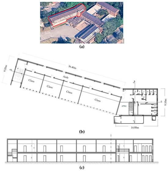
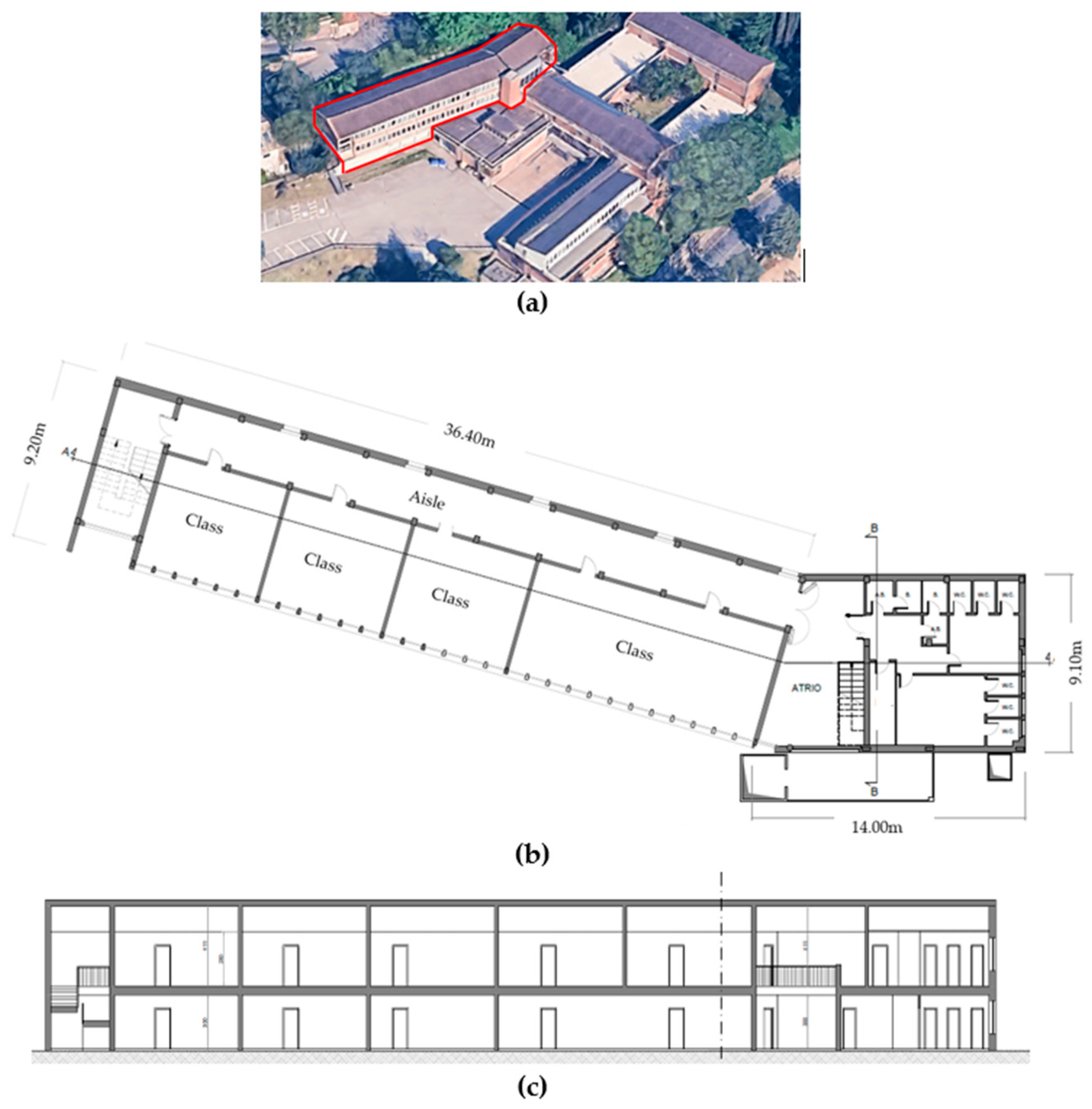
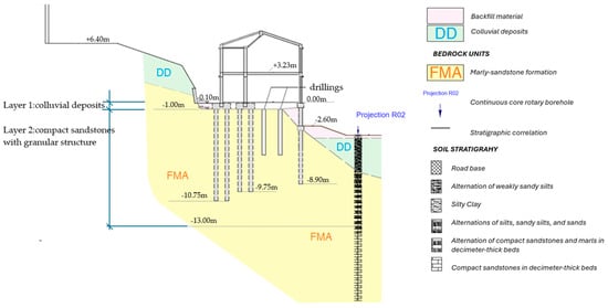
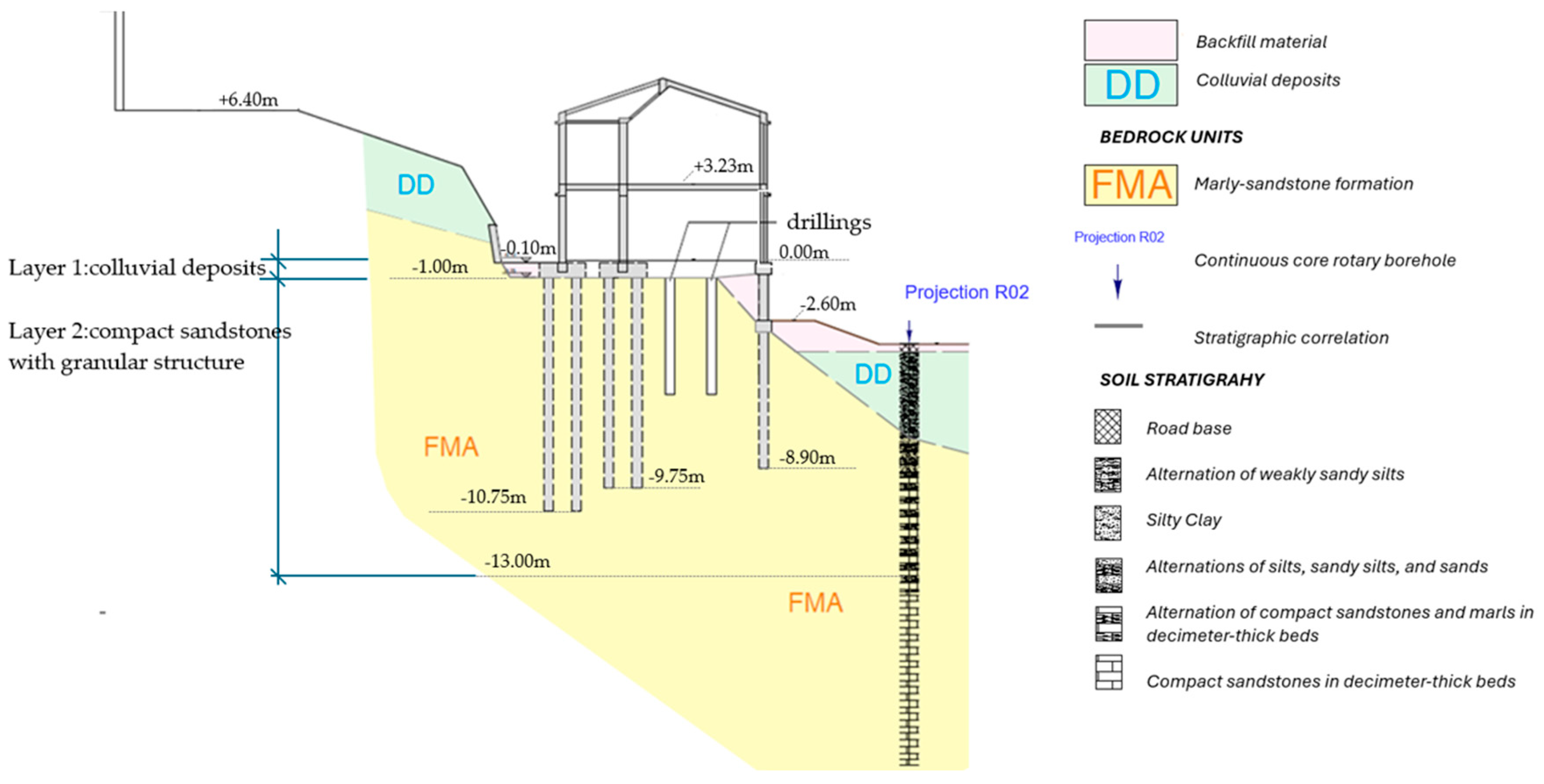
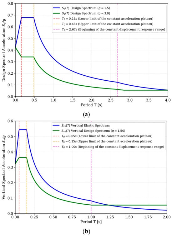
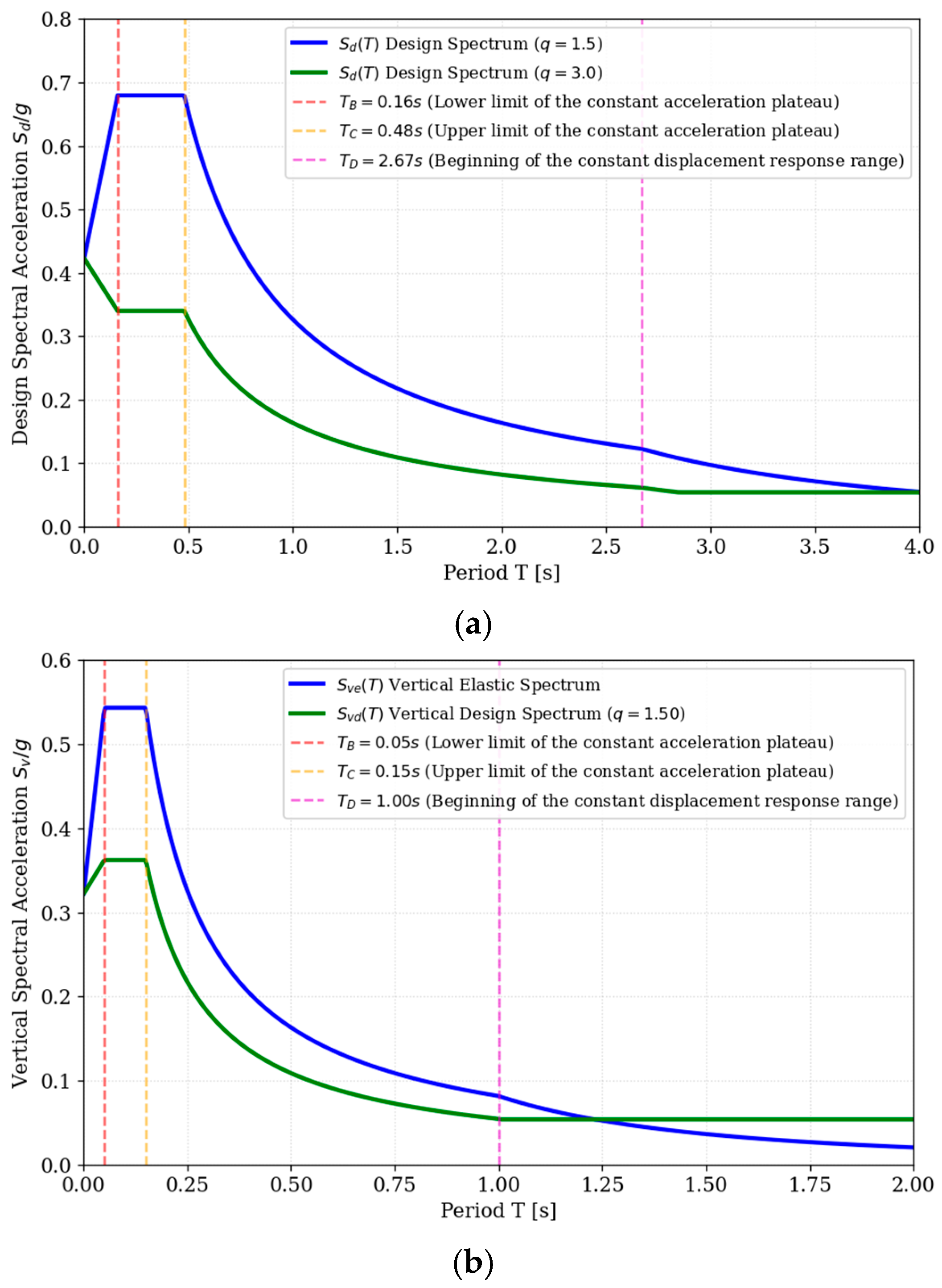
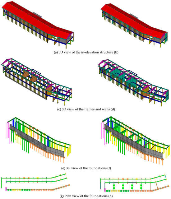
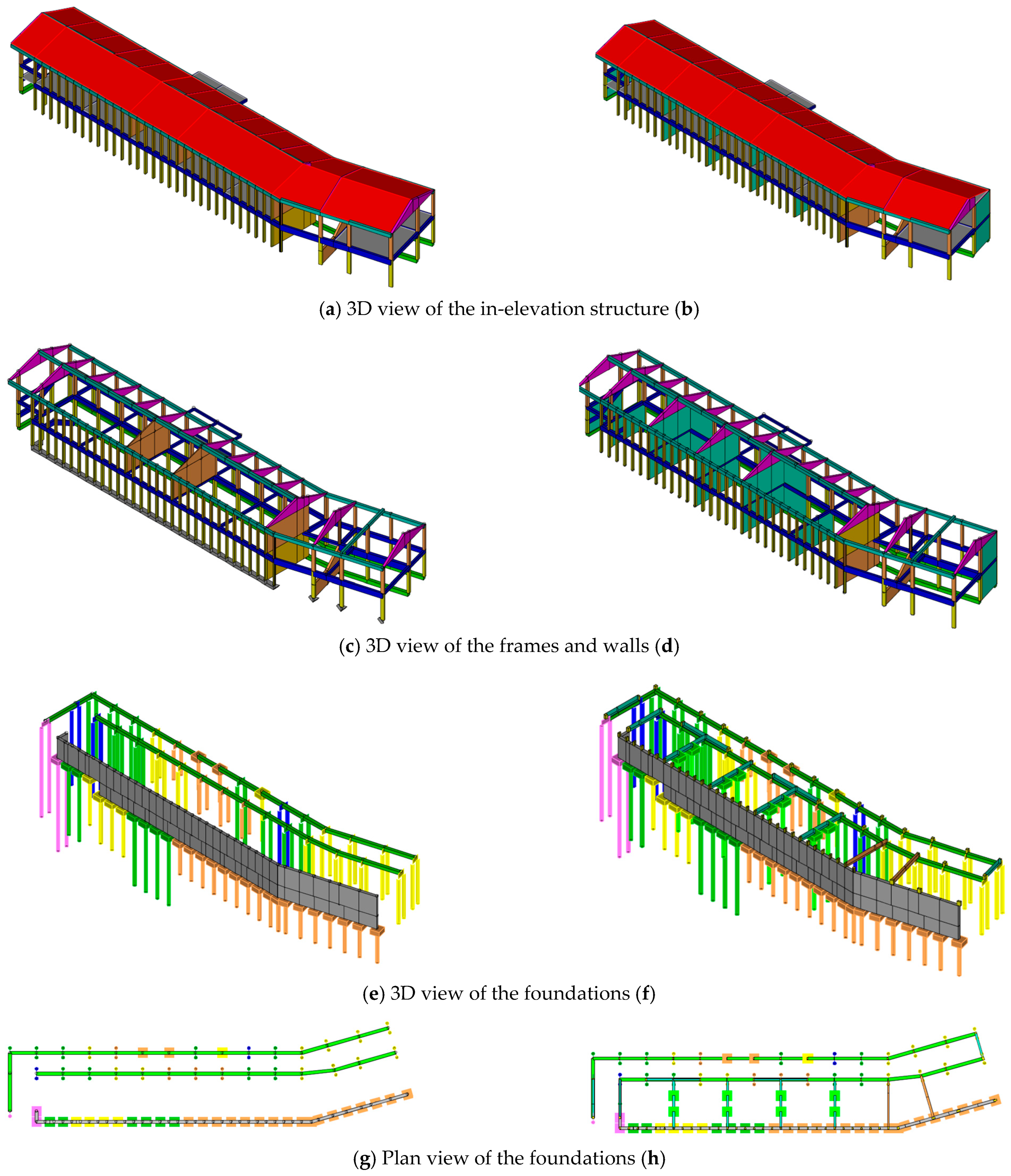
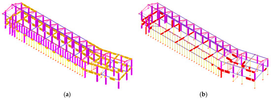
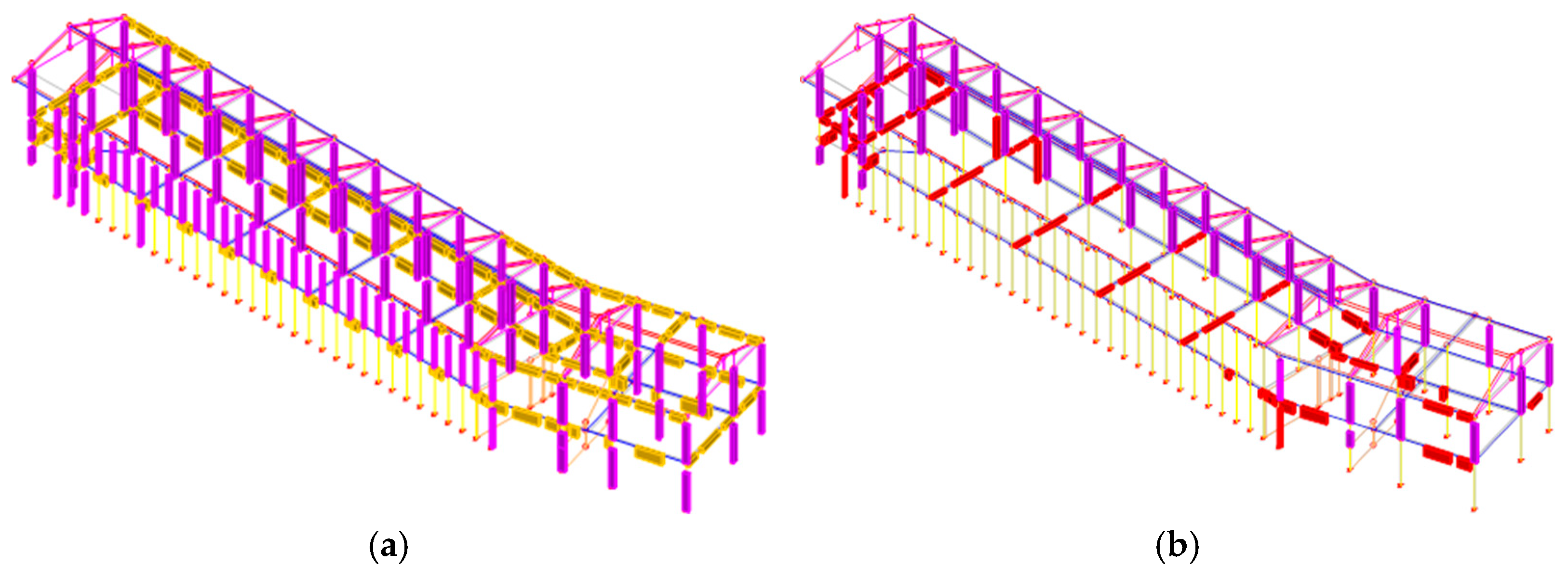
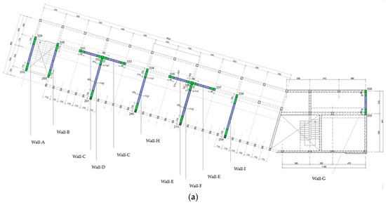
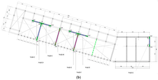
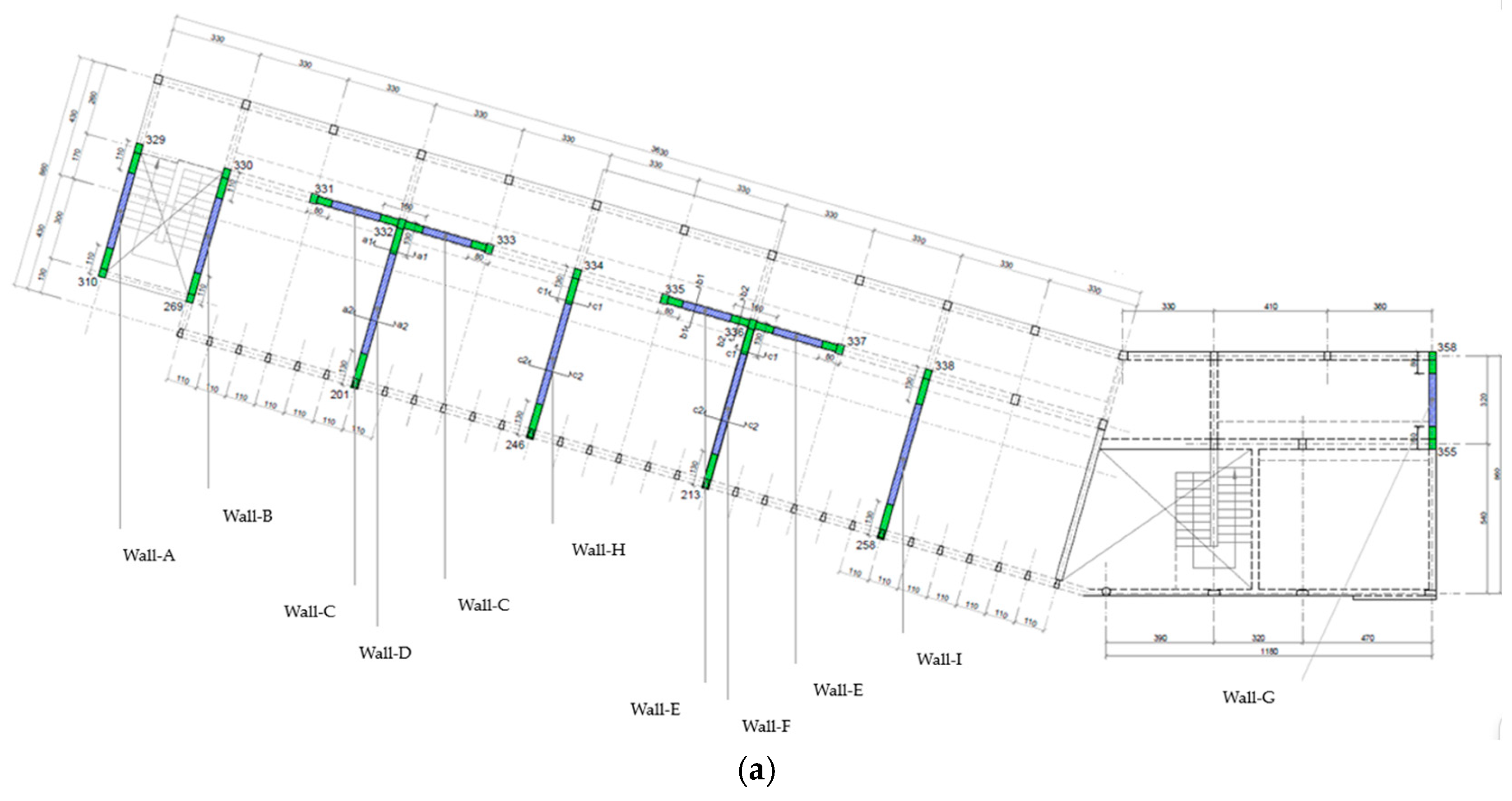
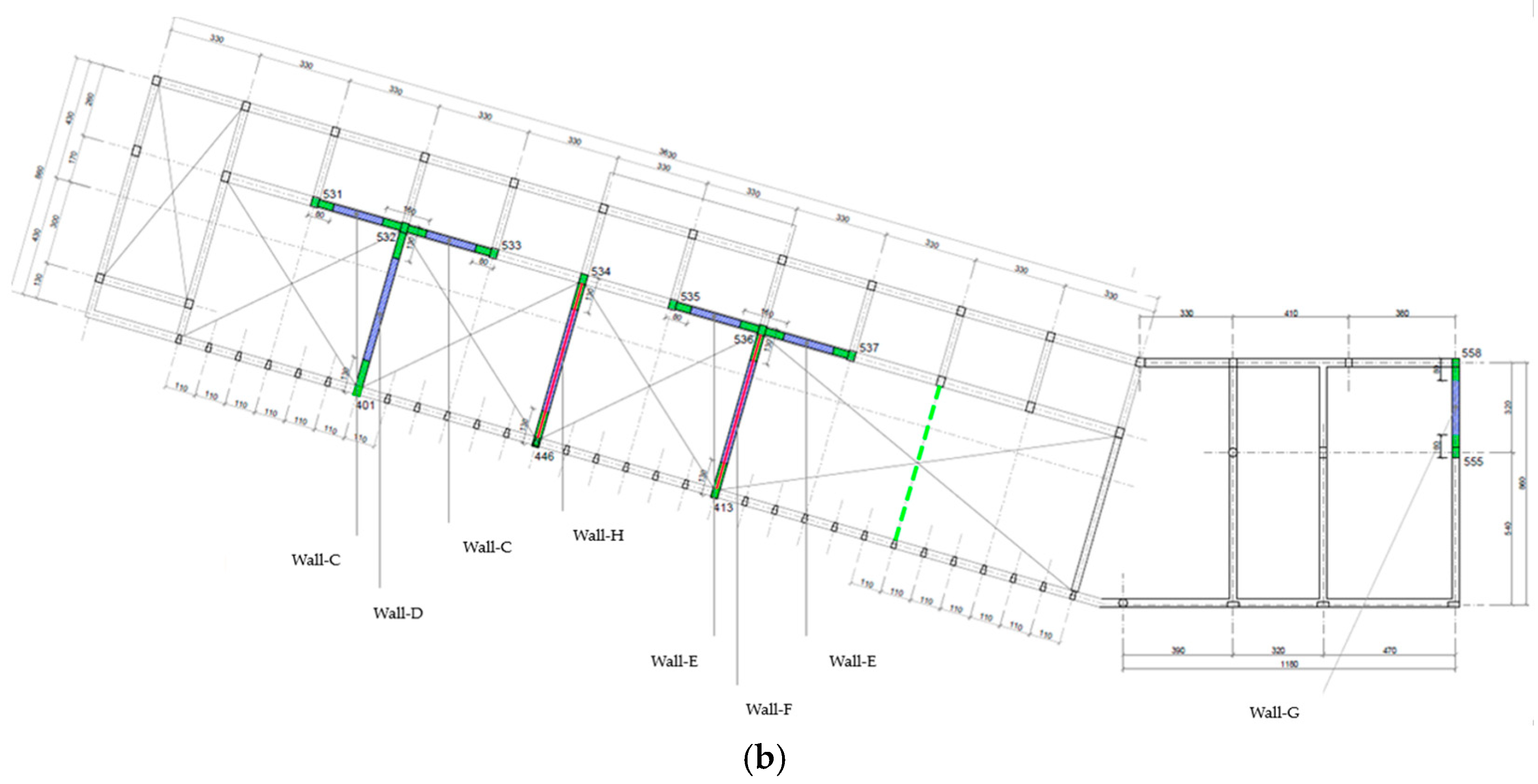
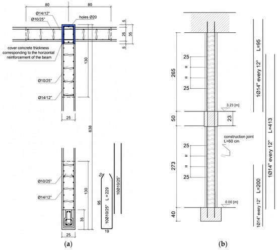
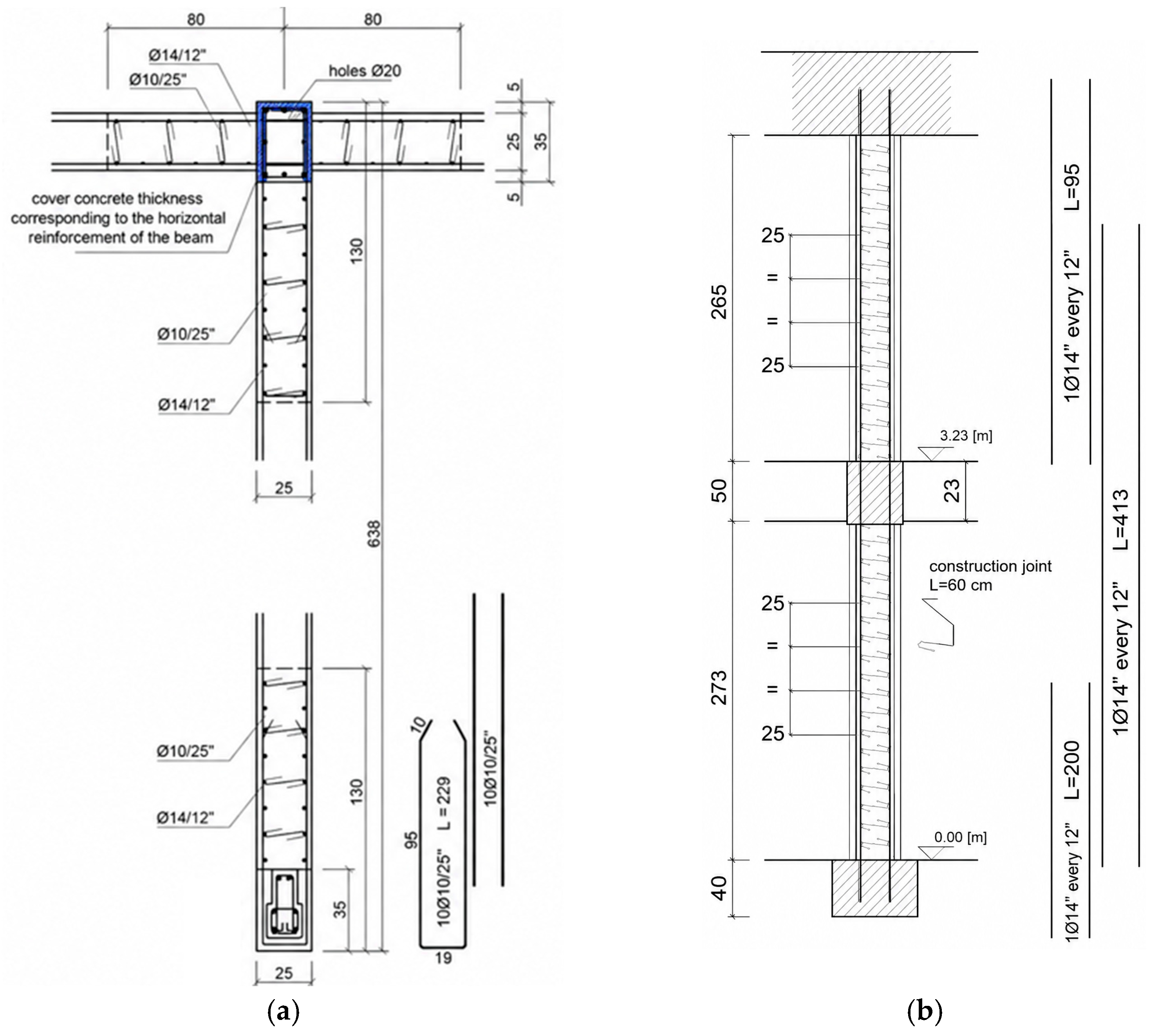
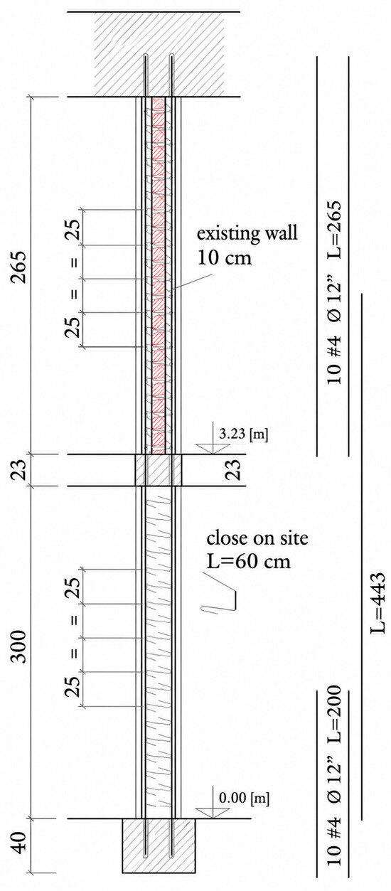
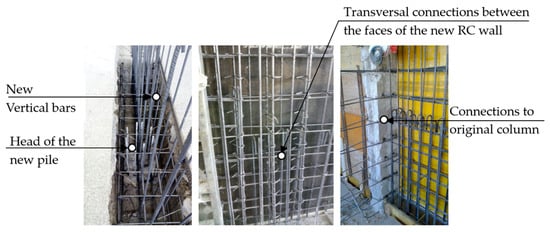
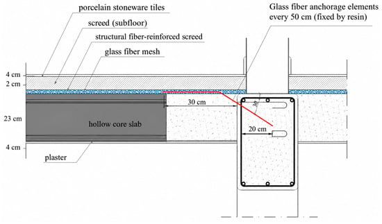
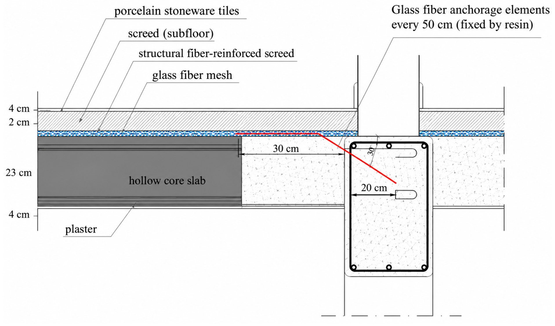
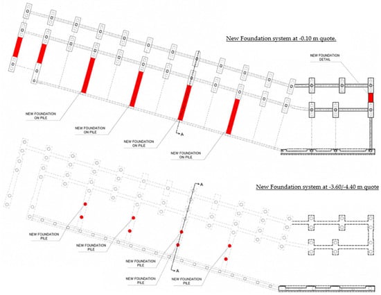
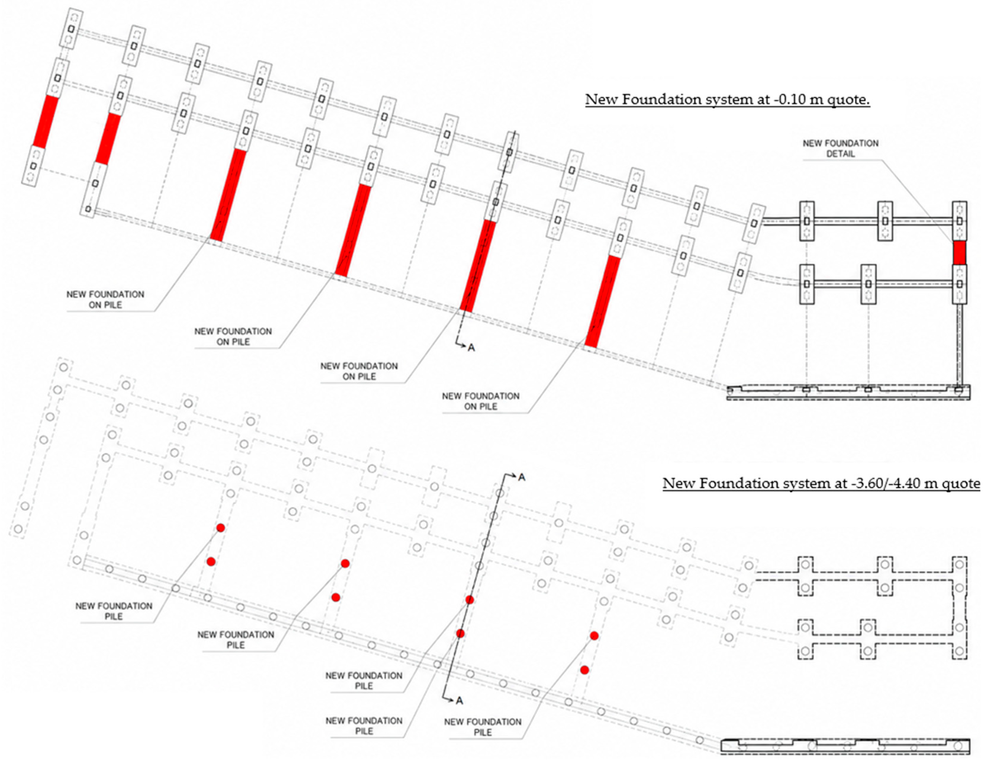
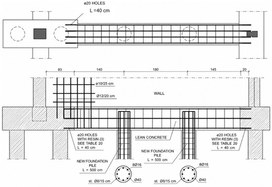
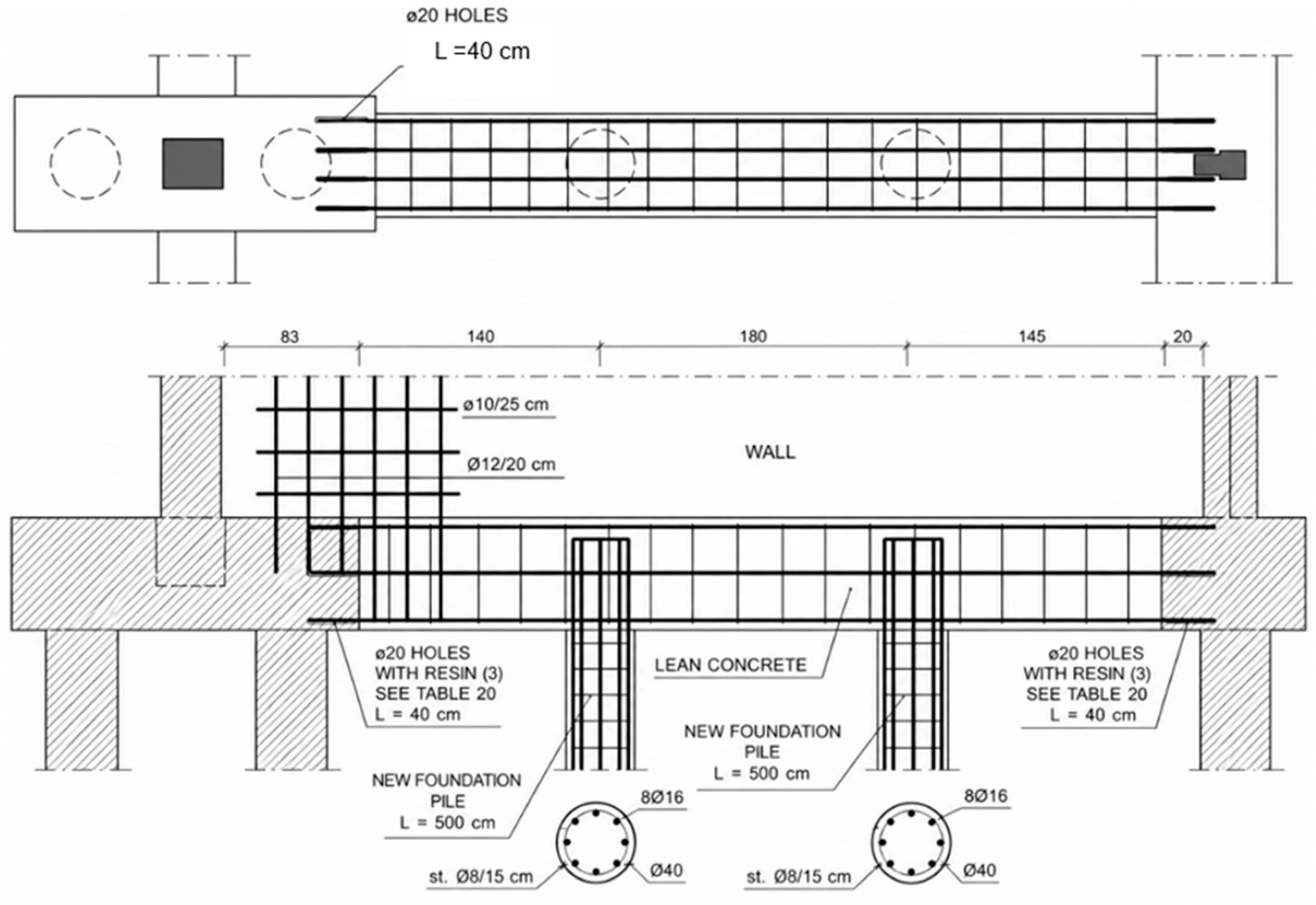
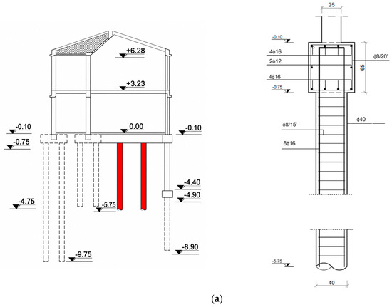
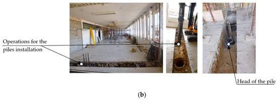
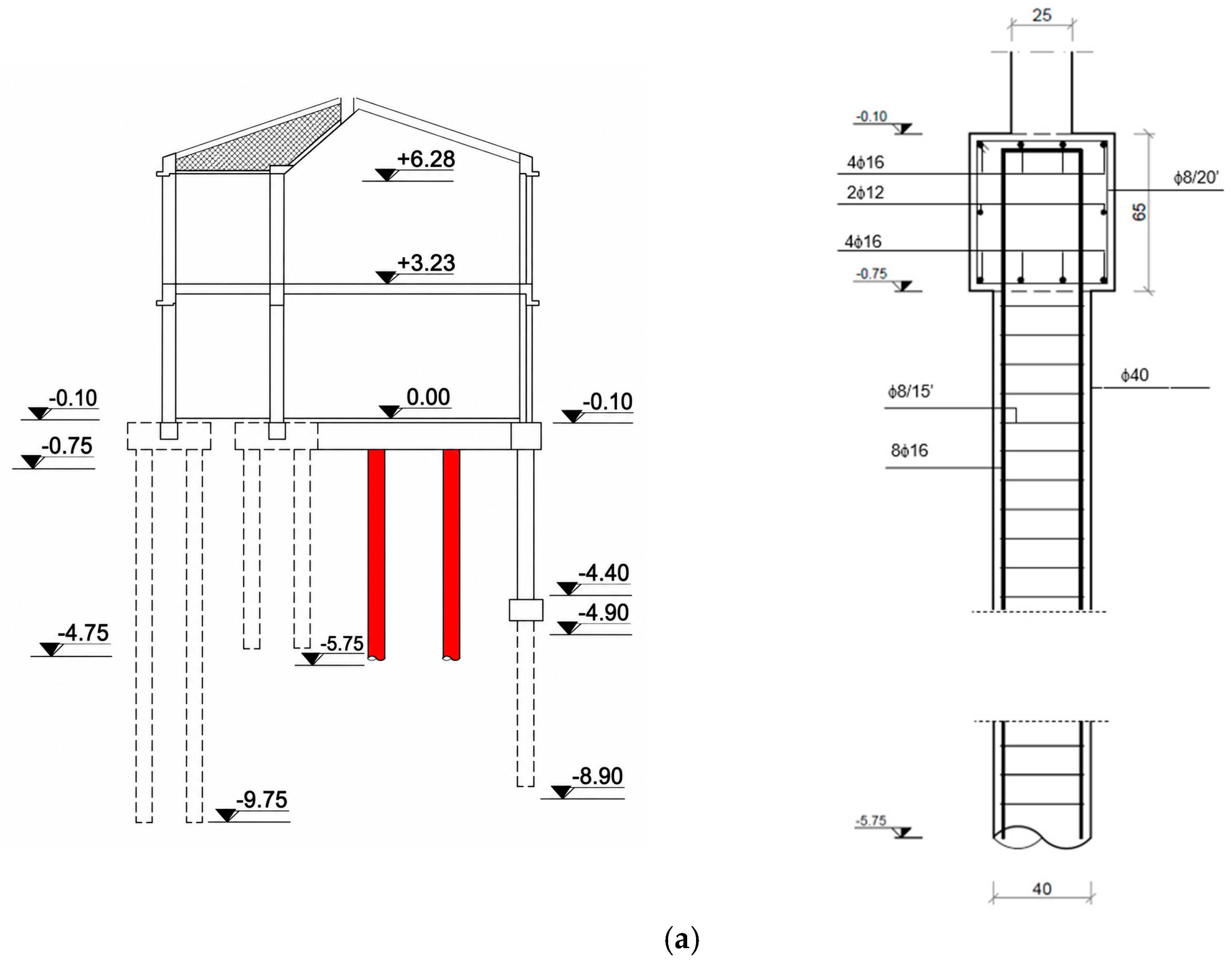
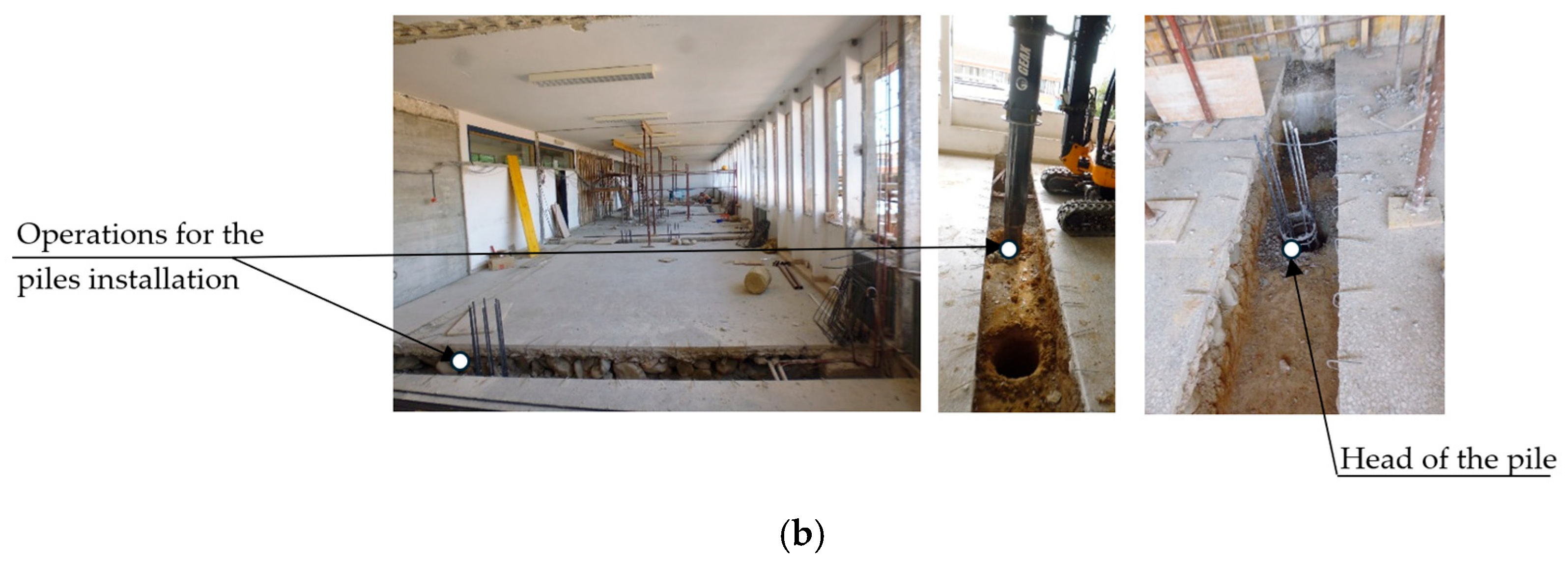
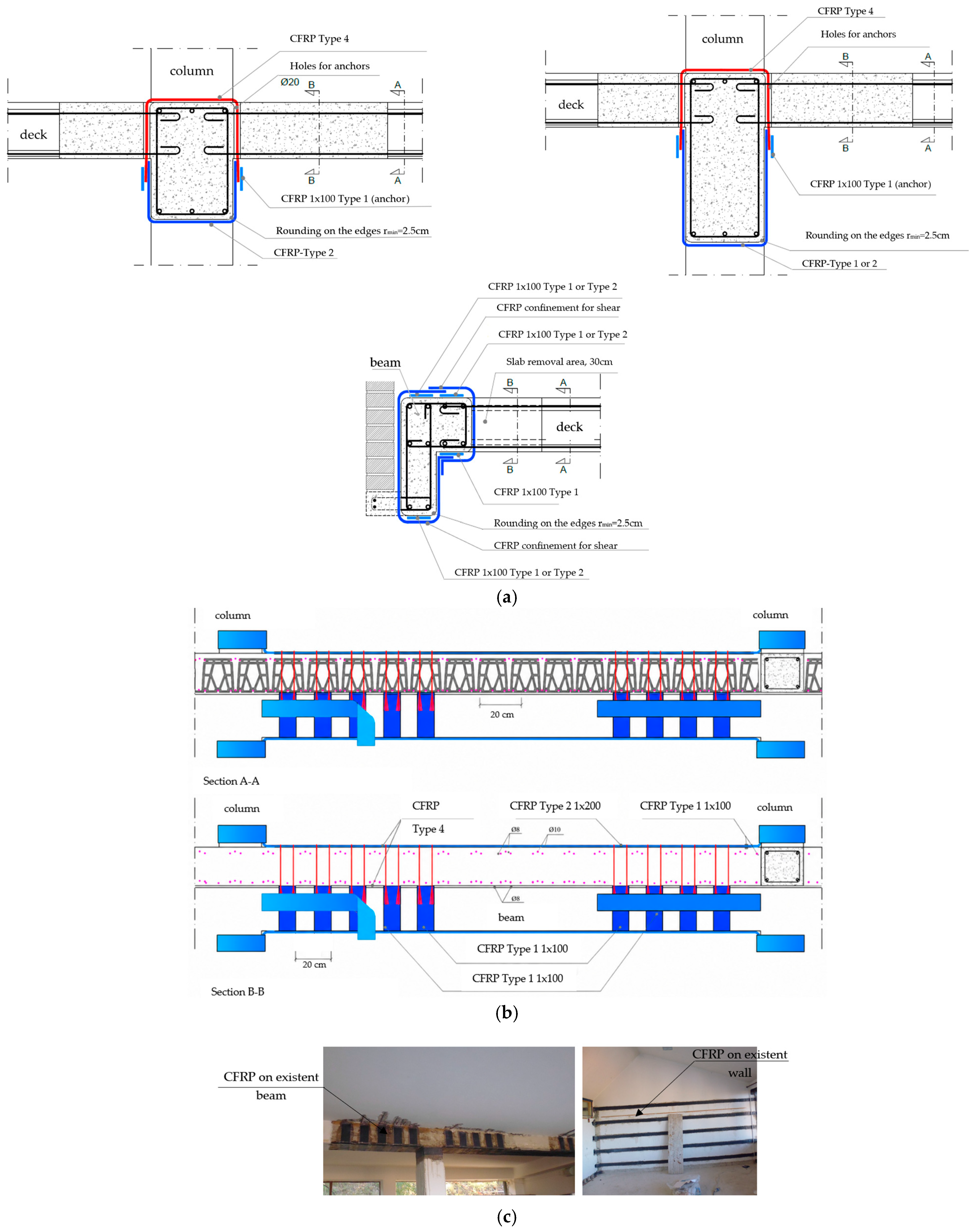
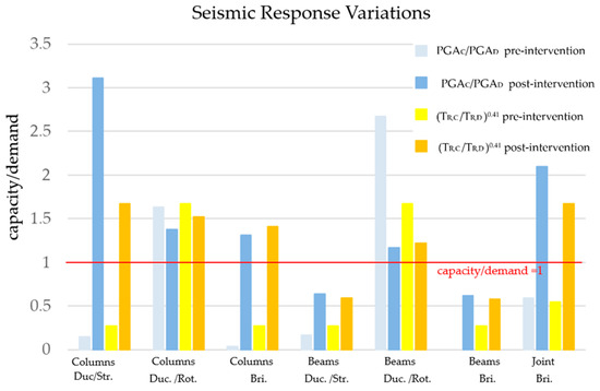
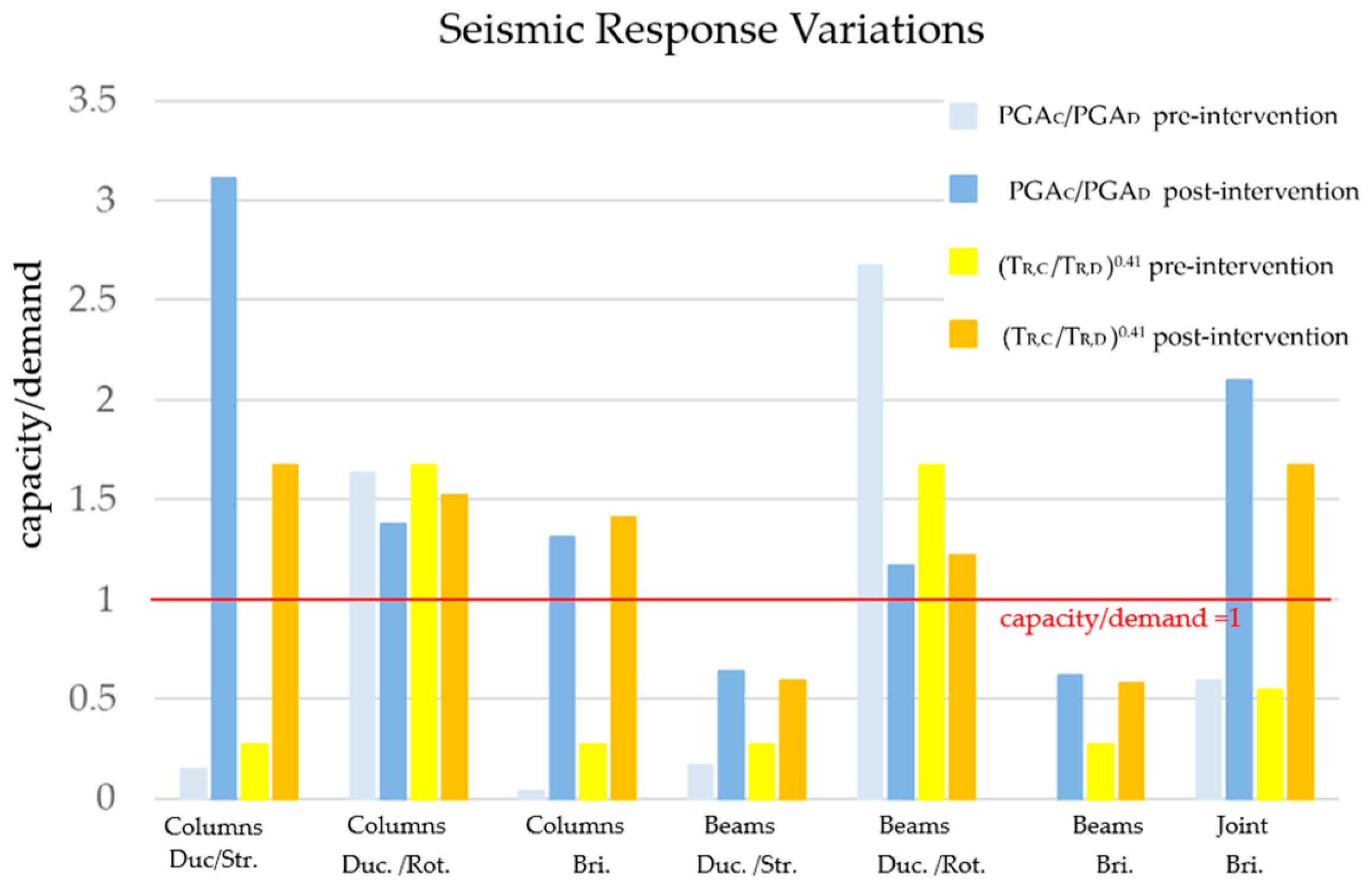
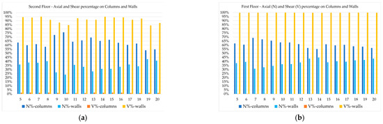
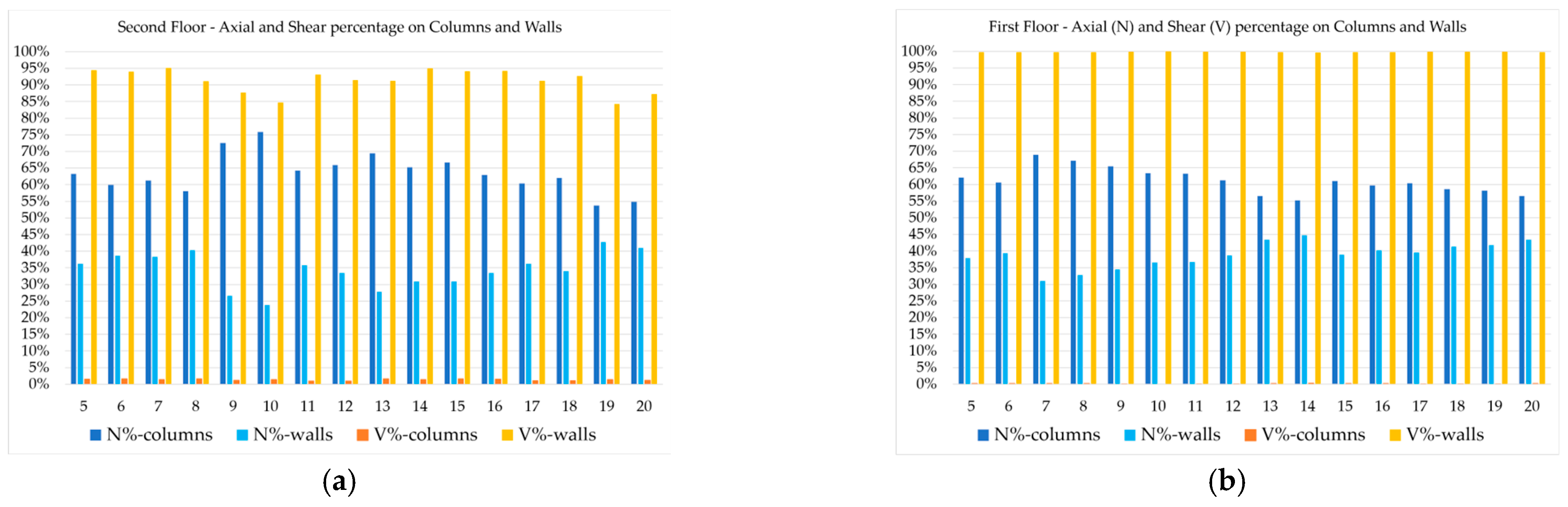
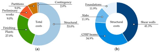
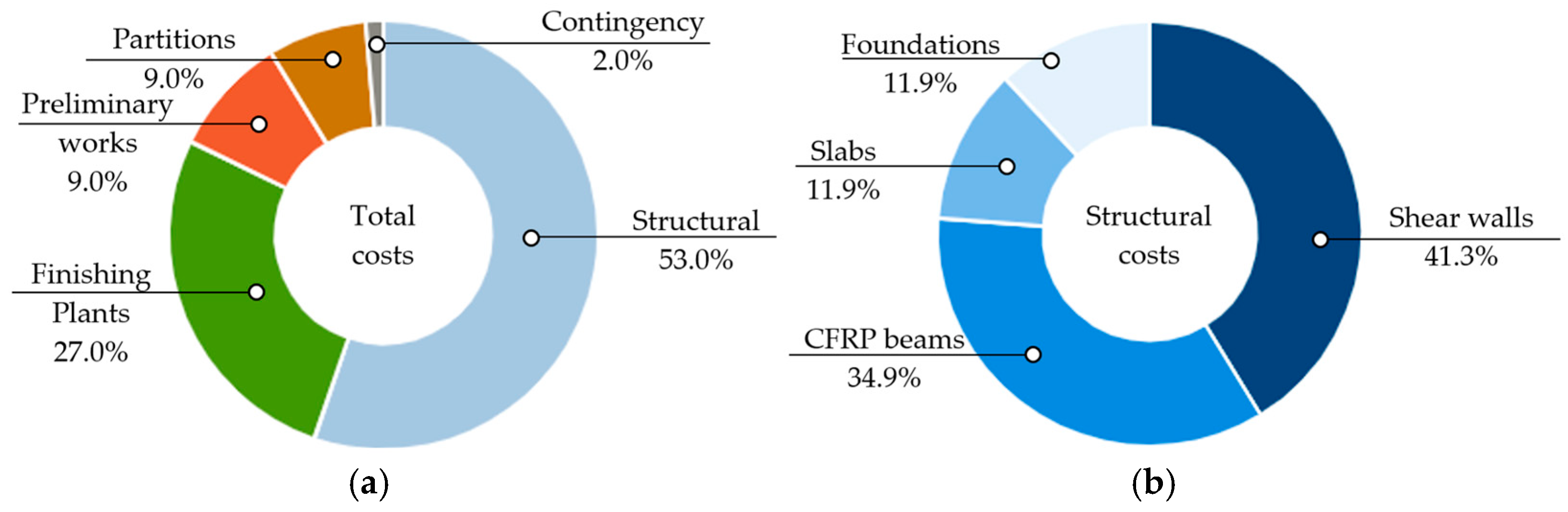
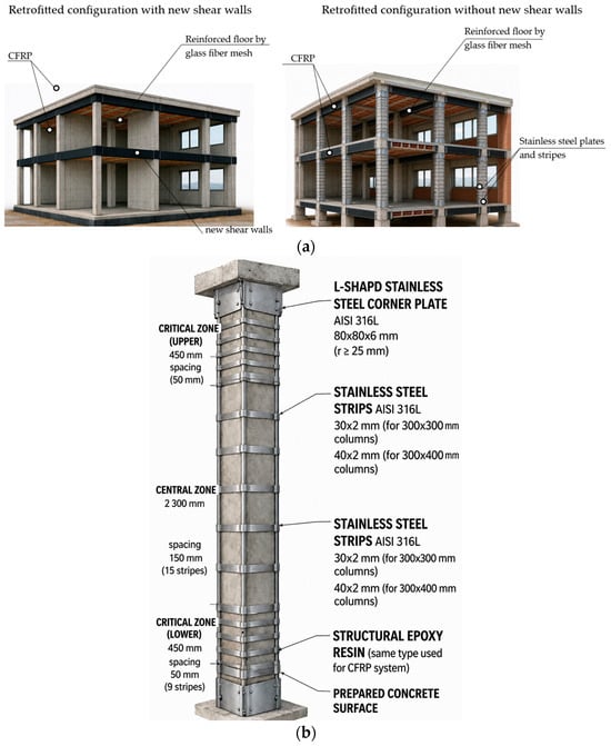
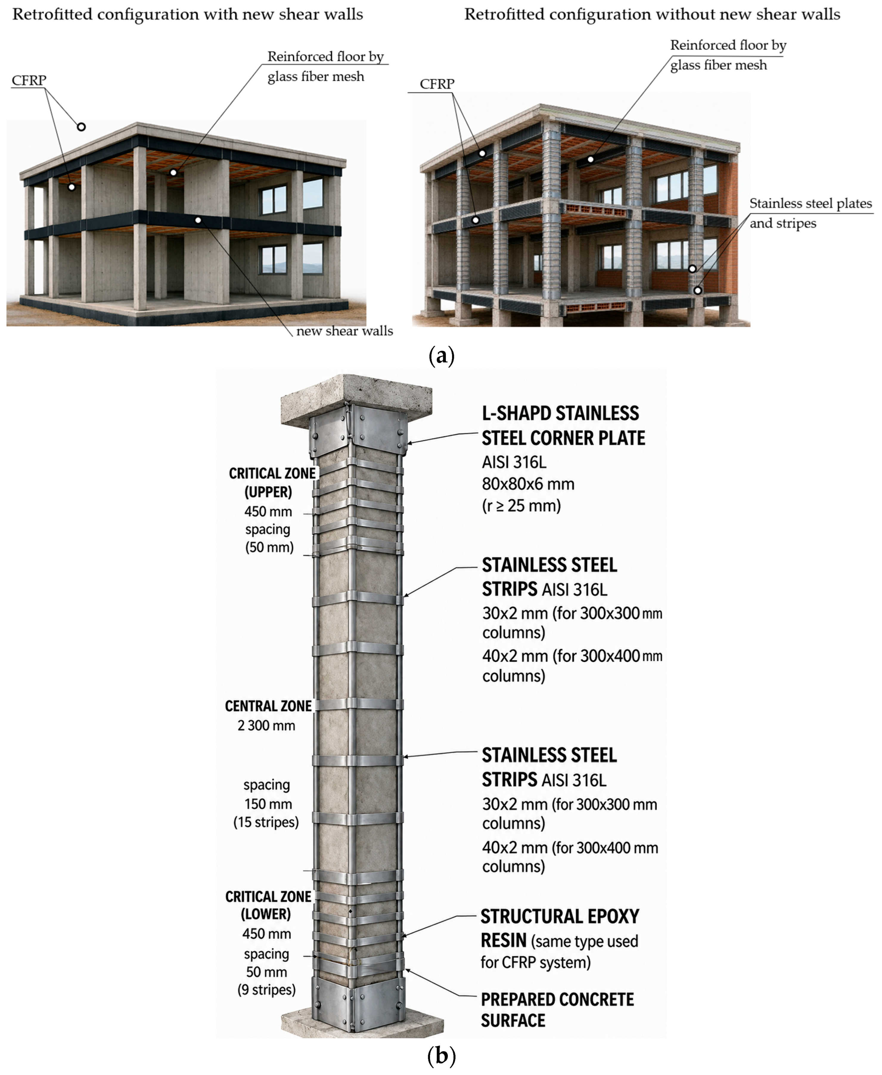

Disclaimer/Publisher’s Note: The statements, opinions and data contained in all publications are solely those of the individual author(s) and contributor(s) and not of MDPI and/or the editor(s). MDPI and/or the editor(s) disclaim responsibility for any injury to people or property resulting from any ideas, methods, instructions or products referred to in the content. |
© 2026 by the author. Licensee MDPI, Basel, Switzerland. This article is an open access article distributed under the terms and conditions of the Creative Commons Attribution (CC BY) license.