


Abstract
Glued-in rod (GIR) connections are widely used in timber composite structures owing to their high load-bearing capacity, high stiffness, and concealed configuration. However, their shear behavior and design methodology under lateral loading remain insufficiently understood. In this study, monotonic shear tests were conducted to clarify the shear failure characteristics and load-transfer mechanisms of steel-to-timber GIR connections. The effects of rod diameter, anchorage length, timber strength grade, and rod orientation relative to the timber grain on the shear performance of the connections were systematically investigated. Self-tapping screw (STS) connections were also tested to compare the shear capacity, deformation behavior, and failure modes of the glued-in rod connections. Based on Johansen’s yield theory and the observed failure modes, shear capacities, and load–slip curves, the shear capacity prediction method and the main influencing factors were evaluated. The results indicate that steel-to-timber GIR connections primarily exhibit a combined failure mode involving timber embedment crushing and rod bending deformation or shear fracture under monotonic shear loading. Shear capacity increases markedly with increasing rod diameter. For the 12 mm rods examined in this study, anchorage length has a limited effect on shear capacity once it exceeds approximately 10d. Connections with rods oriented parallel to the grain demonstrate higher load-carrying capacity and deformation capacity than those with rods perpendicular to the timber grain. Furthermore, the prediction accuracy of the Eurocode 5-based calculation method varies with rod diameter: the calculated capacities agree well with the experimental values for small-diameter rods (10 mm and 12 mm), whereas the predictions for larger-diameter rods (14 mm and 16 mm) are conservative.
1. Introduction
Glued-in rod connections are a common type of structural joint and have been widely adopted in the strengthening of concrete structures and in timber composite systems. In a typical GIR connection, holes are first drilled in the structural member, after which steel rods are inserted into the holes, and the rods are anchored using structural adhesive. Compared with conventional screws and slotted-in steel plate connections, GIR connections offer several advantages, including high load-bearing capacity, high stiffness, and a concealed configuration. These characteristics have made GIR connections an important connection form in steel–timber hybrid structures.
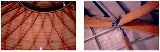
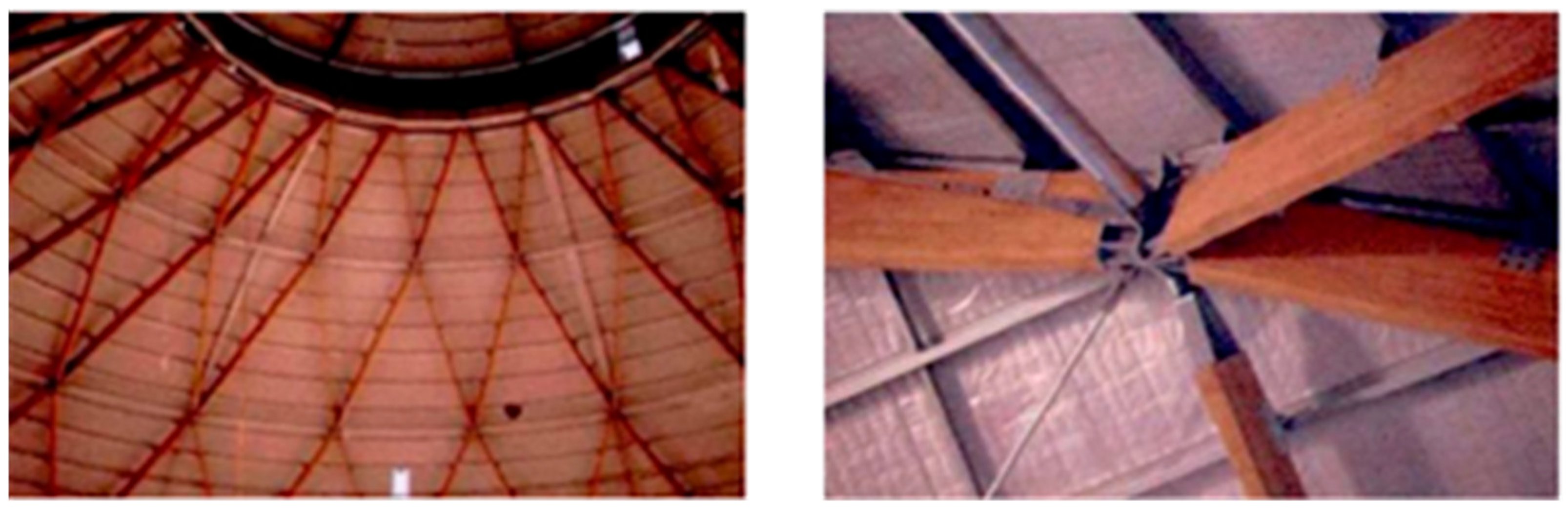
Driven by carbon-reduction targets, steel–timber hybrid structures have been increasingly adopted in large-span public buildings, such as stadiums, exhibition centers, and airport terminals, as illustrated in Figure 1 and Figure 2. Compared with conventional structures, joints in large-span systems are often subjected to relatively high shear forces, which impose more demanding on the shear capacity, stiffness, and deformation capacity of the connections in practical engineering applications. The connection type directly affects the overall safety and serviceability of the structure.
Figure 1.
Physical model of a roof truss joint with a steel-to-timber glued-in rod connection.
Figure 2.
Steel-to-timber connection joint.
Over the past four decades, extensive research has focused on the bond anchorage behavior and failure mechanisms of GIR connections in timber structures under axial tension [1,2,3], and corresponding calculation models for withdrawal capacity have been developed [4,5]. However, the mechanical behavior of timber GIR connections subjected to lateral shear loading has received relatively limited attention. Recent comprehensive reviews have highlighted the significant potential of GIR connections in modern timber structures, while also emphasizing the complexity of their mixed failure modes under lateral loading [6]. Owing to the presence of the adhesive layer, GIR connections differ from conventional dowel-type fasteners, such as nails, bolts, and screws, in terms of their embedment-bearing mechanism and load-transfer path.
For the shear performance of glued-in rod connections in timber–concrete composite systems, Jing [7] conducted push-out tests on GIR connections and investigated the effects of rod diameter, embedment depth and inclination angle on connection shear capacity and stiffness. Rong [8] adopted two types of shear connectors, namely glued-in rods and notch-GIR composite connectors, and studied their shear capacity, stiffness, ductility, and other mechanical properties under different boundary conditions and loading rates through experimental and theoretical analyses.
The shear design of steel-to-timber GIR connections is currently based primarily on the capacity equations for dowel-type fasteners specified in Eurocode 5 [9]. These equations are derived from Johansen’s yield theory [10], in which the minimum value among several possible failure modes is taken as the governing shear capacity, and the contribution of the rope effect is considered through the term Fax,Rk/4 (Fax,Rk/4: Characteristic axial withdrawal capacity). Fawcett and Toumpanaki [11] conducted shear tests on glued-in rods embedded in laminated veneer lumber (LVL) and reported that the code-based prediction of approximately 9.6 kN was substantially lower than the experimental value of 18.4 kN, representing a discrepancy of up to 82%. This difference was attributed primarily to the fact that the design code does not account for the enhancement of timber embedment strength induced by the adhesive layer. Ling [12] experimentally investigated the lateral performance of single glued-in rod connections used in steel plate-to-timber joints. The results demonstrated that GIR connections subjected to shear loading may exhibit either one-hinge or two-hinge failure modes, strongly dependent on anchorage length, and that the load–displacement curves displayed a distinct yield plateau followed by a secondary linear stage, indicating a degree of ductility. Hassanieh et al. [13] conducted push-out tests on steel-cross-laminated timber (CLT) composite connections and showed that the type of shear connector significantly affected the load–slip response, failure mode, stiffness, and ultimate capacity, also enabling the development of empirical slip equations and simplified stiffness models. Gečys et al. [14] experimentally investigated the influence of the rope effect on the slip curves of laterally loaded nailed and screwed timber-to-timber connections.
Glued-in rod connections have been used or proposed in various steel-to-timber structural applications, including steel column–timber beam joints, frame corners, moment-resisting connections, connections involving timber shear walls, steel plate-to-timber joints, and shear connections between steel beams and timber slabs. In these applications, the actual internal force state of the connection depends strongly on the global static scheme, load path, boundary conditions, and possible load eccentricity.
For moment-resisting connections, frame corners, column-base joints, or eccentrically loaded bracket systems, the steel bracket and glued-in rods may form a semi-rigid joint capable of transferring combined shear force, axial force, and bending moment. In such cases, bending moment is often resisted by a tension–compression force couple. The glued-in rods on the tension side mainly carry axial tensile or pull-out forces, while the compression side may be resisted by local timber compression, steel-to-timber contact, or another group of rods. Therefore, the connection behavior may be governed by combined shear and axial tension in the rods, adhesive bond failure, timber splitting, local embedment, or prying action. The response of practical semi-rigid joints therefore cannot be represented by shear transfer alone.
In contrast, in steel plate-to-timber shear-transfer details, such as shear connections between steel beams and timber slabs or local steel plate-to-timber connectors, the primary function of the rods is to transfer lateral shear across the steel–timber interface. When the global axial force and rotational demand are restrained or carried by adjacent structural members, and when the load eccentricity is small, the local response of the glued-in rod can be considered shear-dominated. Under this condition, the main failure mechanisms are expected to involve timber embedment, rod bending or shear deformation, adhesive bond contribution, and the rope effect.
Despite the above studies, several limitations remain in the current understanding and engineering application of steel-to-timber GIR connections under shear loading. First, experimental studies directly focusing on steel-to-timber GIR connections under pure shear or shear-dominated loading remain limited, and their ultimate capacity and failure modes under shear action have not been sufficiently characterized. Second, the key factors governing the shear capacity of timber GIR connections are still not fully understood. Third, existing design methods do not adequately account for the lateral load-bearing mechanism, the rope effect, or the complex stress interaction of steel-to-timber GIR connections, making it difficult to satisfy directly the design requirements of such connections in practical steel–timber hybrid structures.
To address these gaps, this study conducts monotonic single-shear tests on steel-to-timber GIR connections to investigate the effects of rod diameter, anchorage length, timber strength grade, and rod orientation relative to the timber grain on the shear capacity, load–slip behavior, and failure mode. Unlike previous studies that mainly focused on axial pull-out behavior, bond performance, or limited lateral loading cases, this study provides a systematic experimental evaluation of steel-to-timber GIR connections under shear-dominated loading. Self-tapping screw connections are also tested as reference groups, and the applicability of the Eurocode 5-based Johansen model is evaluated by considering both the Johansen load-bearing component and the rope-effect contribution.
2. Experimental Program
2.1. Specimen Design
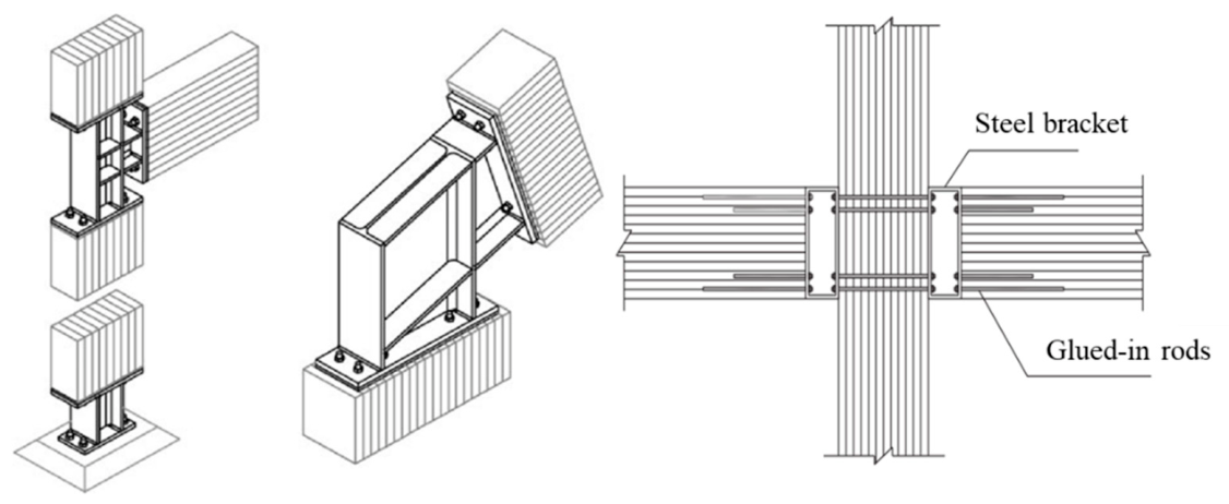
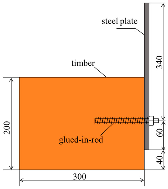
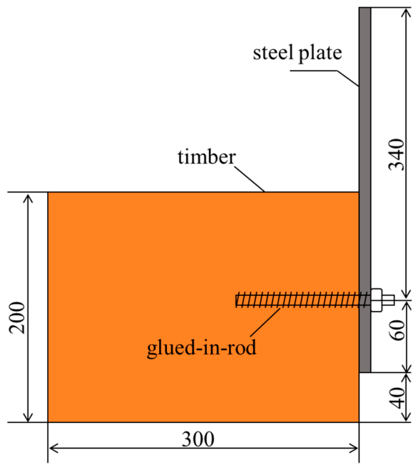
The timber materials used in this study were North American Douglas fir with a strength grade of TCt32 and spruce with a strength grade of TCt28, supplied by Nanjing Shiye Wood Structure Technology Co., Ltd. (Nanjing, China). All glulam specimens were fabricated by bonding 30-mm-thick laminations, with each glulam block measuring 160 mm × 200 mm × 300 mm. Grade 8.8 threaded rods were used as glued-in rods, grade 4.8 self-tapping screws were included for comparison, and Q235 steel plates with dimensions of 160 mm × 400 mm × 12 mm were adopted. All steel components, including the threaded rods and steel plates, were purchased from a steel supplier in Shanghai, China. A total of 13 specimen groups were designed, with three specimens in each group. The test groups were arranged according to five main variables, namely rod diameter, anchorage length, connector type, timber strength grade, and rod orientation relative to the grain, as listed in Table 1. Three specimens were tested for each group. For the groups designed to investigate the effect of rod diameter, a constant anchorage length-to-diameter ratio of 12.5 was adopted with reference to GB 50367-2013 [15], ensuring that specimens with different rod diameters had comparable anchorage conditions and failure mechanisms during shear loading. Figure 3 shows a schematic configuration of the designed connection.
Table 1.
Design parameters of specimens.
Figure 3.
Diagram of the joint.
All specimens consisted of a timber block and a 12-mm-thick steel plate connected by either a glued-in threaded rod or a self-tapping screw. For the GIR connections, the hole diameter was 2 mm larger than the nominal diameter of the threaded rod, resulting in a nominal adhesive layer thickness of approximately 1 mm. For the self-tapping screw connections, pilot holes with a diameter of 10 mm were pre-drilled in the timber members before screw installation. After drilling, the holes were cleaned using compressed air to remove wood dust and loose particles, and the rod surfaces were cleaned before adhesive injection to remove possible oil, dust, or surface contamination. During installation, the rods were slowly inserted into the adhesive-filled holes and kept approximately centered to ensure a relatively uniform adhesive layer. The assembled GIR specimens were then cured under laboratory conditions for 7 days before testing.
2.2. Material Properties
The timber materials used in this study were Douglas fir and spruce, both of which were fabricated into glulam specimens by bonding 30 mm thick laminations. The physical and mechanical properties of the two glulam types are listed in Table 2.
Table 2.
Physical and mechanical properties of the glulam materials.
Table 3.
Mechanical properties of the steel components.
A two-component epoxy adhesive was used to anchor the rods into the timber. The adhesive, supplied by Nanjing Mankate Technology Co., Ltd. (Nanjing, China) under the product model Pubang S309, had the material properties listed in Table 4, as provided by the manufacturer.
Table 4.
Mechanical properties of the epoxy adhesive.
2.3. Test Setup and Loading Protocol
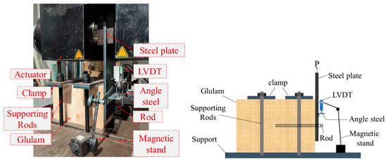
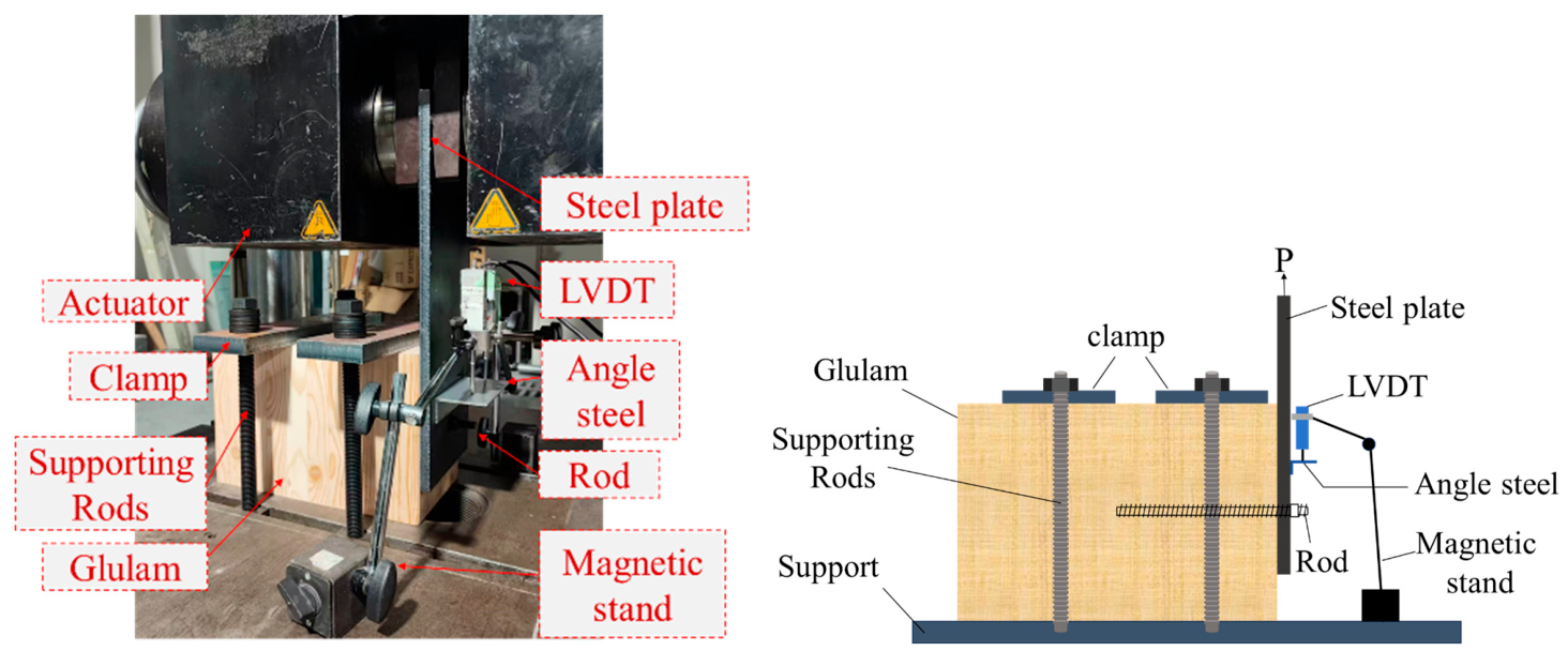
To investigate the shear performance of steel-to-timber GIR connections, monotonic single-shear tests were designed. The test setup is shown in Figure 4. Each specimen was fixed to the support using high-strength threaded rods and clamping plates to prevent overall sliding during loading. The steel plate was connected to the timber specimen through the glued-in rod and nut. The upper end of the steel plate was attached to the loading fixture, and a vertical load was applied to the steel plate by the testing machine, thereby generating a single-shear loading condition between the steel plate and the timber member.
Figure 4.
Test setup.
To measure the relative slip displacement of the steel plate with respect to the timber member, a steel angle bracket was installed on the surface of the steel plate above the rod hole. Two displacement transducers were fixed to the stationary support, with their measuring tips in contact with the steel angle bracket, to record the displacement of the steel plate during loading. The applied load was recorded by the testing machine, and the load–slip curves of the connections were then obtained. The measured displacement was taken as the apparent slip of the connection. It may include minor flexural deformation of the clamping plate. However, because the clamping plate had sufficient thickness and stiffness, no obvious deformation was observed during the tests; therefore, its deformation was considered negligible compared with the measured slip.
A combined force–displacement control loading procedure was adopted in the tests. Before formal loading, each specimen was preloaded to 5% of the estimated ultimate load to eliminate installation gaps and initial contact errors. Displacement-controlled loading was then applied at a rate of 2 mm/min. The test was terminated when pronounced deformation occurred, when the load dropped to 80% of the maximum load, or when the slip displacement reached 30 mm.
3. Experimental Results and Discussion
3.1. Failure Characteristics and Test Observations
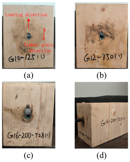
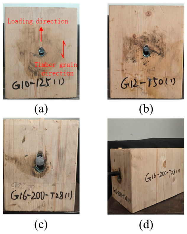
Typical failure modes of some glued-in rod specimens with rods parallel to the grain are shown in Figure 5. Under shear loading, the connections generally exhibited a combined failure mode consisting of local timber crushing and rod bending deformation or rod shear fracture.
Figure 5.
Failure mode of glued-in rod connection parallel to grain. (a) front view of G10-125; (b) front view of G12-150; (c) front view of G16-200-T28; (d) perspective view of G16-200-T28.
During the initial loading stage, both the specimen deformation and the steel plate slip were small. As the applied load increased, the steel plate gradually slipped vertically relative to the timber member and the glued-in rod progressively bent. The timber fibers surrounding the rod underwent compressive deformation under local contact stresses. With further loading, the bending deformation of the rod became more pronounced and plastic deformation developed near the steel plate–timber interface. The load-bearing capacity of the connection gradually approached its peak value. Eventually, significant rod bending deformation was accompanied by progressive crushing of the timber embedment zone and pronounced steel plate slip. The overall failure mode can therefore be classified as a typical bending–embedment failure of a dowel-type connection, as illustrated in Figure 5c,d.
The failure modes of specimens with rods parallel to the grain were significantly influenced by the rod diameter. For specimens with small-diameter rods (10 mm and 12 mm), obvious plastic bending deformation occurred at the interface during the later loading stage. Owing to the local restraint effect, the rods eventually reached their ultimate shear strength and failed by shear fracture, showing pronounced brittle failure characteristics, as illustrated in Figure 5a,b. After failure, the fractured rod ends were tightly compressed against the surrounding timber. Among these specimens, the 12 mm rod specimens exhibited a relatively large ultimate slip. In contrast, for specimens with larger rod diameters (14 mm and 16 mm), no rod shear fracture was observed, and the dominant failure mode was significant bending deformation. At the same time, local compressive deformation appeared around the wall of the steel plate hole, and partial squeezing-out of the adhesive layer was observed at the interface.
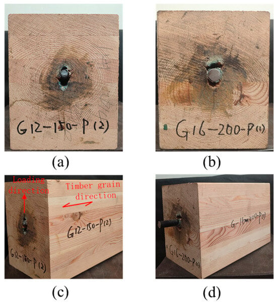
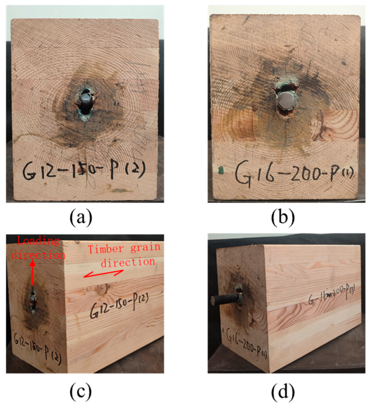
The failure process of specimens with rods perpendicular to the grain differed markedly from that of parallel-to-grain specimens. Due to the lower mechanical properties of timber in the perpendicular-to-grain direction, the timber surrounding the rod was more susceptible to severe embedment crushing and local tearing along the grain. Continuous crushing and splitting sounds were observed during the tests. Compared with the parallel-to-grain specimens, local compressive damage to the timber was more pronounced in the perpendicular-to-grain specimens, as shown in Figure 6.
Figure 6.
Failure mode of glued-in rod joint perpendicular to grain. (a) front view of G12-150-P; (b) front view of G16-200-P; (c) perspective view of G12-150-P; (d) perspective view of G16-200-P.
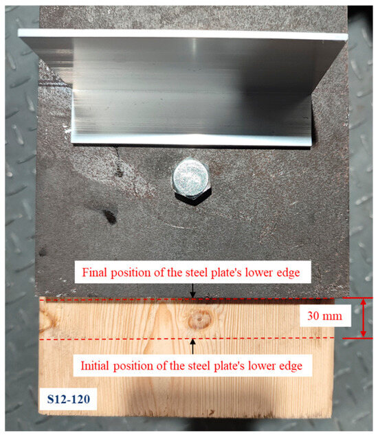
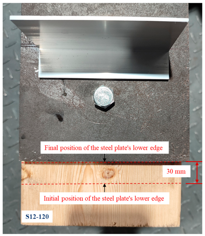
No obvious shear fracture occurred in the self-tapping screw connections during the entire test process. These connections exhibited good slip capacity, and the ultimate slip could reach the displacement limit of 30 mm at the end of loading without fracture. This indicates that such connections were still able to maintain a certain load-carrying capacity at large deformation stages, as shown in Figure 7.
Figure 7.
Slip behavior of self-tapping screw joint with steel plate.
3.2. Summary of Experimental Results
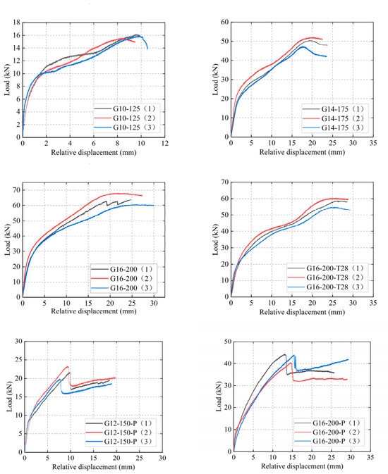
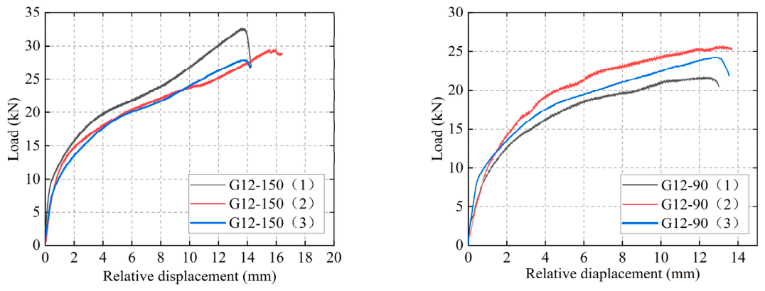
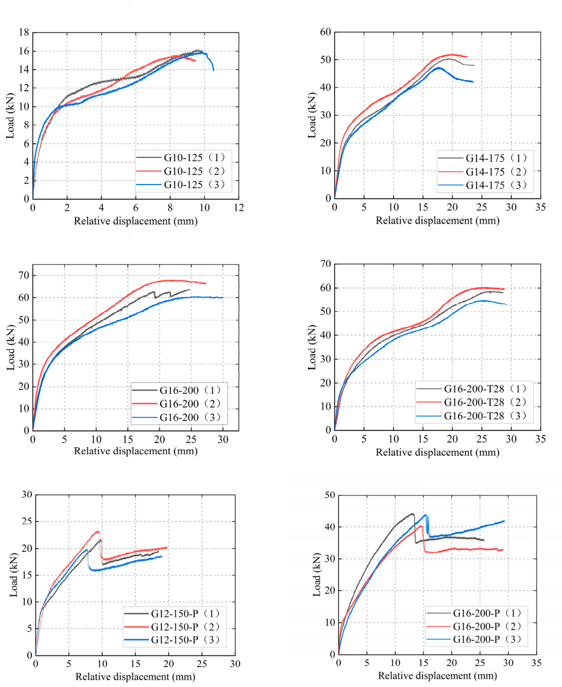
Table 5 summarizes the main experimental data of all specimens, including the maximum load, corresponding slip, initial stiffness, ductility coefficient, and failure mode. The average value and coefficient of variation are also provided for each group to show the repeatability and scatter of the test results. The corresponding load–slip curves are shown in Figure 8 to illustrate the mechanical response of the connections during loading. All experimental curvesin this study were plotted using Origin software (Version 2024, OriginLab Corp., Northampton, MA, USA).
Table 5.
Summary of test results.
Figure 8.
Load–relative displacement curves.
The coefficients of variation in Table 5 indicate that the maximum load generally showed acceptable repeatability, whereas larger scatter was mainly observed in slip- and ductility-related parameters. This variability may be related to progressive timber embedment, local damage development, and post-yield deformation of the connections.
3.3. Effects of Key Variables on Load–Slip Behavior
Representative load–slip curves were used in this section to compare the effects of different variables. For each selected specimen group, the representative curve was taken from the specimen whose maximum shear capacity and initial stiffness were closest to the corresponding group mean values.
3.3.1. Effect of Anchorage Length
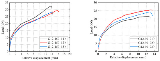
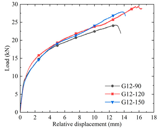
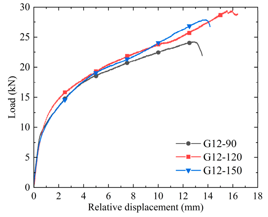
Figure 9 presents the load–slip curves of the 12 mm GIR specimens with three different anchorage lengths. As shown, the shear capacity varied only slightly with increasing anchorage length, and no consistent improvement attributable to increased anchorage length was observed. This suggests that the load-bearing capacity of the GIR connection was governed primarily by the shear resistance of the rod itself rather than by the anchorage length. For the 12 mm rods examined in this study, once the anchorage length reached approximately 7.5d–10d, the connection was generally able to satisfy the shear load-bearing requirements. It should be noted that this finding is specific to the 12 mm rod specimens tested herein and should not be generalized to other rod diameters without further experimental evidence.
Figure 9.
Load–slip curves for different anchorage lengths.
3.3.2. Effect of Rod Diameter
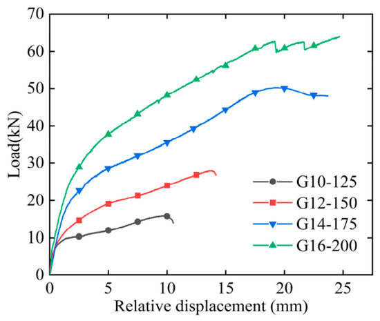
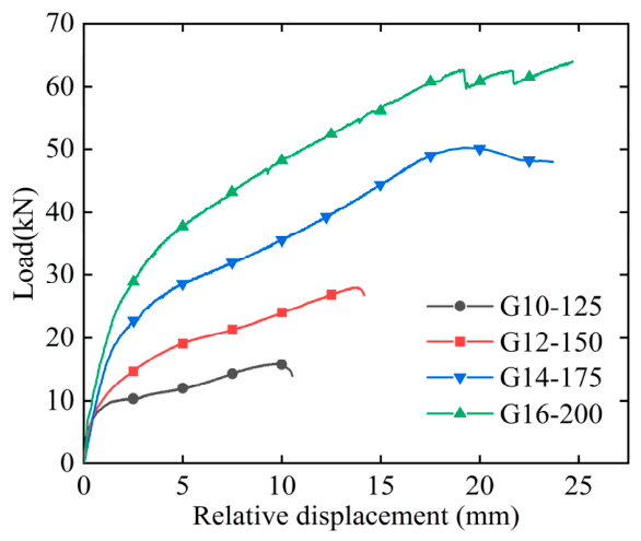
Figure 10 presents the load–slip curves of the specimens with different rod diameters under a constant anchorage length-to-diameter ratio. It can be observed that the shear capacity of the connections increased significantly with increasing rod diameter. The specimens with 10 mm and 12 mm rods exhibited relatively small ultimate slips and experienced shear fracture shortly after reaching the peak load, showing pronounced brittle failure characteristics. In contrast, the specimens with 14 mm and 16 mm rods showed stronger plastic deformation capacity and were still able to maintain a certain load-bearing level after reaching the peak load. It should be noted that, under the adopted constant anchorage-length-to-diameter ratio, the absolute anchorage length also increased proportionally with rod diameter.
Figure 10.
Load–slip curves for varying diameters.
The enhancement in shear performance with increasing rod diameter can be explained by two mechanisms. First, a larger rod diameter increased the bending stiffness and shear resistance of the rod, reducing the likelihood of local shear fracture at relatively low load levels. Second, a larger rod mobilized a wider timber embedment zone, thereby improving the overall load-bearing and deformation capacities of the connection. Therefore, under the present test conditions, increasing the rod diameter at a constant anchorage-length-to-diameter ratio improved the shear performance of the steel-to-timber GIR connections. It should be noted that the absolute anchorage length also increased with rod diameter in these groups.
3.3.3. Effect of Rod Orientation to the Grain
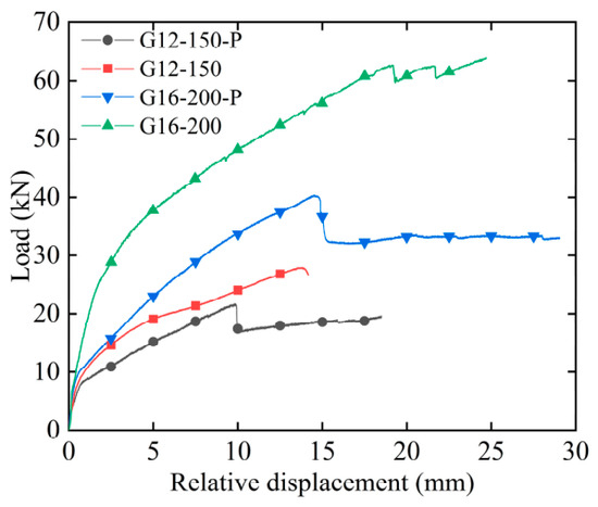
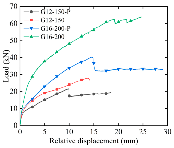
Figure 11 presents the load–slip curves of GIR specimens with rods oriented parallel and perpendicular to the grain. Both the yield shear capacity and the ultimate shear capacity of the parallel-to-grain specimens were substantially higher than those of the perpendicular-to-grain specimens, indicating that rod orientation relative to the grain direction had a significant influence on the shear performance of GIR connections. When loaded parallel to the grain, the timber primarily experienced local crushing and densification, and the load-bearing capacity increased relatively steadily, resulting in superior deformation capacity. In contrast, when loaded perpendicular to the grain, the lower compressive and tensile strengths of timber in this direction rendered the specimens more susceptible to local brittle splitting failure. Consequently, the load–slip curves exhibited a pronounced post-peak load drop, followed by a residual yielding stage sustained by the deeper timber region.
Figure 11.
Load–slip curves for different rod orientations.
This behavior is also evident in Figure 6, which shows local crushing and splitting of the timber in the region surrounding the perpendicular-to-grain rod. Although this damage was localized, it did not result in failure of the overall timber cross-section.
3.3.4. Effect of Glulam Strength Grade
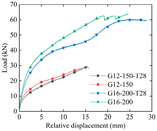
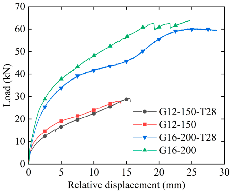
Figure 12 presents the load–slip curves of Douglas fir and spruce specimens. Based on the curve profiles and the observed final failure states, the ultimate shear capacity of the Douglas fir specimens was generally slightly higher than that of the spruce specimens, and the Douglas fir connections sustained higher shear loads at equivalent slip levels. These results indicate that the glulam strength grade and local embedment-bearing performance exerted a measurable influence on the shear performance of the connections. Compared with spruce, Douglas fir exhibited higher local embedment-bearing capacity and a higher elastic modulus, enabling greater stiffness and load-bearing capacity during interfacial load transfer.
Figure 12.
Load–slip curves for two glulam strength grades.
3.3.5. Comparison Between Glued-in Rod and Self-Tapping Screw Connections
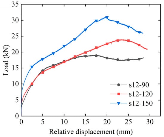
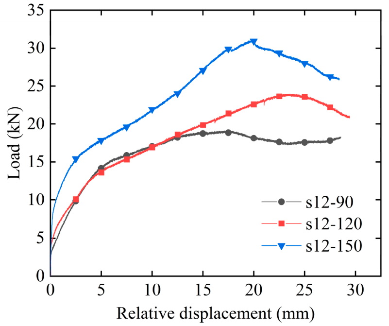
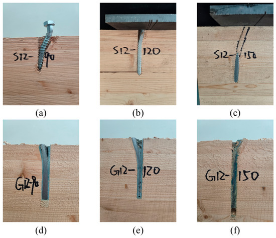
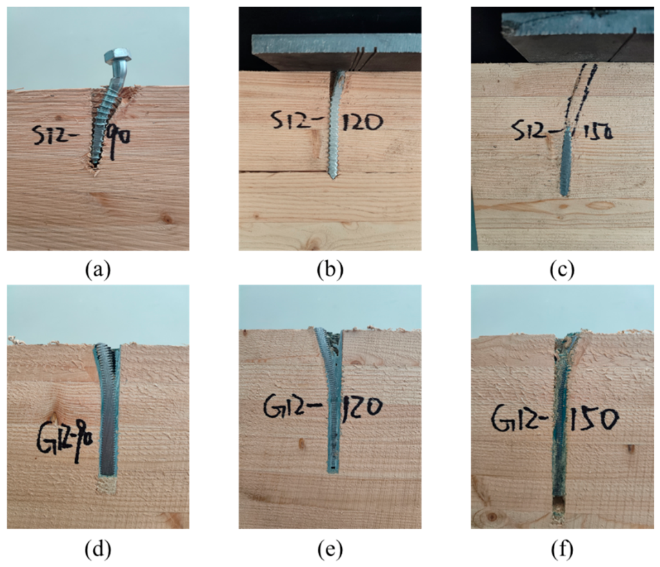
Figure 13 and Figure 14 present the load–slip curves of the self-tapping screw connections and the failure morphology sections of the self-tapping screw group and the 12 mm glued-in rod group, respectively. It can be observed that the shear capacity of the self-tapping screw connections increased significantly with increasing anchorage length. When the anchorage length increased from 90 mm to 120 mm, the average ultimate capacity increased from 20.83 kN to 24.86 kN. When the anchorage length further increased to 150 mm, the average ultimate capacity reached 31.33 kN. This indicates that anchorage length is an important parameter affecting the shear capacity of self-tapping screw connections. Within the range of 7.5d–12.5d, increasing the anchorage length made a considerable contribution to the improvement of shear capacity. A greater anchorage length enhanced the restraint provided by the timber to the screw and promoted more sufficient plastic development of the screw, thereby enabling a higher load-bearing capacity.
Figure 13.
Load–slip curve of the self-tapping screw joint.
Figure 14.
Profile of failure morphology. (a) S12-90; (b) S12-120; (c) S12-150; (d) G12-90; (e) G12-120; (f) G12-150;
In contrast, the shear capacity of the glued-in rod connections was less sensitive to variations in anchorage length. As discussed in Section 3.3.1, for the 12 mm rods, once the anchorage length reached approximately 10d, further increasing it had only a limited effect on improving the shear capacity. Compared with the self-tapping screw reference specimens, the GIR specimens showed different load–slip responses and lower sensitivity of shear capacity to anchorage length. This difference is related to the adhesive bond and more continuous load transfer along the bonded rod, whereas the self-tapping screw specimens were more dependent on thread–timber interaction and anchorage length.
4. Theoretical Analysis of Shear Capacity
4.1. Calculation Theory for Shear Capacity
According to Eurocode 5, the characteristic load-bearing capacity of a single-shear steel-to-timber dowel-type connection comprises two components: the Johansen load-bearing component and the rope-effect component. The Johansen component is governed by timber embedment bearing and fastener bending or shear deformation, while the rope-effect component is associated with the axial withdrawal resistance of the fastener. Under lateral shear loading, a glued-in rod can be regarded as a dowel-type fastener because the load is transferred through local embedment of timber and deformation of the rod. Therefore, the Eurocode 5-based Johansen model was adopted in this study as a reference method for estimating the shear capacity of steel-to-timber GIR connections.
GIR connections differ from conventional bolts or screws in that the adhesive layer modifies the bond behavior and load transfer between the rod and the surrounding timber. In the present calculation, this effect was incorporated through the withdrawal capacity of the glued-in rod, which contributes to the rope-effect term. Since the current design code does not provide explicit provisions for the shear capacity of steel-to-timber GIR connections, the rope-effect contribution was limited to 25% of the Johansen component in accordance with Eurocode 5. The shear capacity was therefore calculated as Equation (1):
where Fv,Rk is the shear capacity of the connection; fh,k is the embedment strength of the timber member; t1 is the anchorage length of the fastener in timber; d is the fastener diameter; My,Rk is the characteristic yield moment of the fastener; and Fax,Rk is the withdrawal capacity of the connection.
The embedment strength parallel to the grain is calculated by Equation (2):
The embedment strength for different loading directions can be calculated by Equation (3):
where α is the angle between the loading direction and the grain direction. For loading perpendicular to the grain, α = 90°. Therefore, the embedment strength perpendicular to the grain can be expressed as Equation (4):
According to Eurocode 5, the characteristic yield moment of the fastener is given by Equation (5):
where fu,k is the characteristic ultimate tensile strength of the fastener.
The calculation equations for Fax,Rk are as follows:
The calculation model of axial withdrawal capacity of screws reported in Eurocode 5 is expressed as Equation (6), indicating that the axial withdrawal capacity of screws is influenced by diameter of screws, penetration length of screws, and timber density.
where fv,k is the characteristic withdrawal strength parameter of screws, lthr is the effective anchorage length, and is the characteristic timber density.
For glued-in rod connections, previous studies have shown that the withdrawal resistance of rods embedded in timber is significantly higher than that of screws under the same conditions. Considering the effect of the adhesive layer, the withdrawal capacity Fax,Rk can be calculated as Equations (8)–(10) [17]:
where ta is the thickness of the adhesive layer.
The calculated withdrawal capacities of all specimen groups were greater than the 25% limit of the Johansen load-bearing component. Therefore, for the glued-in rod groups, the shear capacity was calculated using the 25% limitation.
4.2. Comparative Analysis of Theoretical and Experimental Results
The theoretical values calculated using the above method are compared with the experimental values in Table 6.
Table 6.
Comparison between theoretical and experimental shear capacities.
The comparison reveals that when the shear capacity of GIR connections was calculated with reference to Eurocode 5 and the rope-effect contribution was limited to 25% of the Johansen component, relatively accurate predictions were obtained for small-diameter rods and perpendicular-to-grain connections, with discrepancies within 20%. This agreement may be attributed to the occurrence of rod shear fracture or local splitting failure, which constrained the full development of the rope effect; the 25% limitation therefore reasonably prevented the onset of additional unfavorable failure modes in these cases. However, for large-diameter rods (14 mm and 16 mm) oriented parallel to the grain, the predictions were conservative: the measured ultimate loads substantially exceeded the calculated values based on the 25% limitation. This suggests that a higher rope-effect contribution factor may be more appropriate for estimating the shear capacity of large-diameter GIR connections. For the small-diameter rod specimens (10 mm and 12 mm) that failed by rod shear fracture, it should be noted that the Johansen model assumes plastic bending of the fastener rather than brittle shear fracture; the theoretical values for these groups are therefore approximations, and the relatively good agreement may be partly attributable to the conservative nature of the 25% rope-effect limit.
5. Conclusions
In this study, the shear performance of steel-to-timber GIR connections was experimentally investigated. The main variables considered were anchorage length, rod diameter, timber strength grade, and rod orientation relative to the timber grain. Based on the experimental results and theoretical analysis, the following conclusions can be drawn:
(1) Under lateral shear loading, the steel-to-timber glued-in rod connections mainly exhibited a combined failure mode involving local timber crushing and rod bending deformation or rod shear fracture. The rod failure mode was strongly dependent on rod diameter. For small-diameter rods (10 mm and 12 mm), shear fracture occurred during loading, whereas larger-diameter rods (14 mm and 16 mm) mainly exhibited bending deformation without shear fracture.
(2) Rod diameter was a key factor governing the shear performance of the connections. At a constant anchorage-length-to-diameter ratio, increasing the rod diameter from 10 mm to 16 mm improved the shear capacity and deformation capacity of the connections significantly. In contrast, for the 12 mm rods in this study, anchorage length had a limited influence on the shear capacity of the glued-in rod connections. Once the anchorage length reached a certain range, approximately 10d, further increasing the anchorage length had no obvious effect on improving the shear capacity.
(3) Rod orientation relative to the timber grain had a significant influence on the mechanical performance of the connections. The shear capacity and overall deformation capacity of the specimens with rods parallel to the grain were greater than those of the specimens with rods perpendicular to the grain. In perpendicular-to-grain specimens, local timber crushing and tearing along the grain were more pronounced, resulting in brittle failure and preventing the full development of rod bending deformation capacity.
(4) The Eurocode 5-based calculation method demonstrated reasonable applicability for predicting the ultimate shear capacity of GIR connections. For small-diameter rods, calculated values incorporating a rope-effect contribution limited to 25% of the Johansen component were in relatively good agreement with experimental results. However, this limitation was overly conservative for larger rod diameters. For large-diameter rods commonly employed in large-span structural applications, a higher rope-effect contribution may be considered to account for the enhanced load-bearing contribution of the adhesive layer.
Author Contributions
Conceptualization, H.G. and J.C.; methodology, M.P. and H.G.; formal analysis, H.G.; investigation, H.G. and J.C.; resources, M.P. and J.C.; data curation, H.G.; writing—original draft preparation, H.G.; writing—review and editing, M.P., J.C. and J.P.; project administration, M.P. and J.P.; funding acquisition, M.P. All authors have read and agreed to the published version of the manuscript.
Funding
This research received no external funding.
Data Availability Statement
The data presented in this study are available on request from the corresponding author.
Acknowledgments
The authors would like to thank the study participants and research assistants who contributed to data collection.
Conflicts of Interest
The authors declare no conflicts of interest.
References
- Azinović, B.; Serrano, E.; Kramar, M.; Pazlar, T. Experimental investigation of the axial strength of glued-in rods in cross laminated timber. Mater. Struct. 2018, 51, 143. [Google Scholar] [CrossRef] [Scilit]
- Ling, Z.; Yang, H.; Liu, W.; Liao, Y. Local bond stress-slip relationships between glue laminated timber and epoxy bonded-in GFRP rod. Constr. Build. Mater. 2018, 170, 1–12. [Google Scholar] [CrossRef] [Scilit]
- Ling, Z.; Xiang, Z.; Liu, W.; Yang, H.; Tang, J. Load-slip behaviour of glue laminated timber connections with glued-in steel rod parallel to grain. Constr. Build. Mater. 2019, 227, 117028. [Google Scholar] [CrossRef] [Scilit]
- Yeboah, D.; Taylor, S.; McPolin, D.; Gilfillan, R. Behaviour of joints with bonded-in steel bars loaded parallel to the grain of timber elements. Constr. Build. Mater. 2011, 25, 2312–2317. [Google Scholar] [CrossRef] [Scilit]
- Ogrizovic, J.; Wanninger, F.; Frangi, A. Experimental and analytical analysis of moment-resisting connections with glued-in rods. Eng. Struct. 2017, 145, 322–332. [Google Scholar] [CrossRef] [Scilit]
- Tesfamariam, S.; Woods, J.; Teweldebrhan, B.T.; Lam, F. Moment-resisting timber frames using mechanical fastener and adhesive connections: Review and experimental tests. Can. J. Civ. Eng. 2026, 53, 1–23. [Google Scholar] [CrossRef] [Scilit]
- Jing, C. Research on Mechanical Properties of Glued-in Rod Connections in Timber-Concrete Composite Structures. Ph.D. Dissertation, Dalian University of Technology, Dalian, China, 2019. [Google Scholar]
- Rong, X. Study on Mechanical Behavior of Timber-Concrete Composite Beams Under Different Boundary Conditions and Loading Rate. Master’s Thesis, Suzhou University of Science and Technology, Suzhou, China, 2021. [Google Scholar]
- prEN 1995-2; Eurocode 5: Design of Timber Structures—Part 2: Bridges (Final Project Team Draft). European Committee for Standardization: Brussels, Belgium, 2003.
- Johansen, K.W. Theory of timber connections. Int. Assoc. Bridge Struct. Eng. 1949, 9, 249–262. [Google Scholar]
- Fawcett, D.; Toumpanaki, E. Combined effects of axial and lateral loading for glued-in steel rods in laminated veneer lumber. Structures 2023, 57, 105310. [Google Scholar] [CrossRef] [Scilit]
- Ling, Z.; Rong, X.; Xiang, Z. Laterally loaded performance of single dowel-type fastener used for steel plate-to-timber connections. Structures 2021, 34, 1985–1997. [Google Scholar] [CrossRef] [Scilit]
- Hassanieh, A.; Valipour, H.R.; Bradford, M.A. Load-slip behaviour of steel-cross laminated timber (CLT) composite connections. J. Constr. Steel Res. 2016, 122, 110–121. [Google Scholar] [CrossRef] [Scilit]
- Gečys, T.; Bader, T.K.; Olsson, A.; Seim, W. Influence of the rope effect on the slip curve of laterally loaded, nailed and screwed timber-to-timber connections. Constr. Build. Mater. 2019, 228, 116702. [Google Scholar] [CrossRef] [Scilit]
- GB 50367-2013; Code for Design of Strengthening Concrete Structure. China Architecture & Building Press: Beijing, China, 2014.
- BS EN 12512-2001; Timber Structures-Test Methods-Cyclic Testing of Joints Made with Mechanical Fasteners. BSI: Brussels, Belgium, 2001.
- prEN 1995-2; Draft Rules for Bonded-in Rods (Second Draft). LICONS: Brussels, Belgium, 2003; Extract from prEN 1995-2: 2003; Eurocode 5—Design of Timber Structures, Part 2: Bridges.

Disclaimer/Publisher’s Note: The statements, opinions and data contained in all publications are solely those of the individual author(s) and contributor(s) and not of MDPI and/or the editor(s). MDPI and/or the editor(s) disclaim responsibility for any injury to people or property resulting from any ideas, methods, instructions or products referred to in the content. |
© 2026 by the authors. Licensee MDPI, Basel, Switzerland. This article is an open access article distributed under the terms and conditions of the Creative Commons Attribution (CC BY) license.