


Abstract
This paper investigates the seismic performance of precast concrete shear-wall subassemblies connected by post-cast ultra-high performance concrete (UHPC) zones and short lap-spliced reinforcement with a lap length of , where d denotes the diameter of the reinforcement bar. Seven quasi-static cyclic tests were conducted, including one cast-in-place control specimen, five specimens with horizontal UHPC back-cast joints at the wall base, and one exploratory specimen with both horizontal and vertical UHPC back-cast joints. The variables considered were the joint arrangement and the axial compression ratio. The specimens with horizontal joints generally exhibited compression-flexure-dominated damage, and the crushing zone shifted from the wall-footing interface to the ordinary concrete immediately above the UHPC back-cast zone. The specimen with the vertical joint (TW6) exhibited bending-shear damage, accompanied by limited in-plane lateral slip at the beam–wall joint and shear damage of several vertical bars. Specimen TW2, with an axial compression ratio of 0.30, was identified as a construction-quality-sensitive case because an insufficient local UHPC cover caused splitting damage and reduced hysteretic stability. The strain measurements indicate that, within the limits of the present instrumentation, the 10d lap in the UHPC zone provided effective stress transfer in the tested specimens; however, direct interface-slip and bond-slip tests are still required for generalized design verification. Under an axial compression ratio of 0.20, TW1 and TW6 showed comparable seismic indices to the cast-in-place specimen, but the conclusions are limited to the tested configurations. All specimens reached ultimate drift ratios greater than 1/100, and their seismic performance is discussed together with failure mode, stiffness degradation, energy dissipation, and connection reliability.
1. Introduction
The presence of numerous horizontal and vertical joints in assembled shear walls underscores the significance of the reinforcement connection forms at these joints, which are crucial technologies that directly influence the overall seismic performance of the structure. In China, the current JGJ 1-2014 [1], “Technical Specification for Precast Concrete Structures”, recommends connection technologies, such as sleeve grouting connections [2,3,4,5,6,7] and slurry anchor lap connections [8,9,10,11,12,13]. Although the assembled shear walls connected using these two methods exhibit similar seismic performance to monolithic cast-in walls, the sleeve grouting connection presents several disadvantages, including a high quantity of sleeves, stringent construction accuracy requirements, challenges in reinforcing bar buttressing, and difficulties in quality detection. Conversely, the slurry anchor lap connection necessitates hole-by-hole grouting, involves a substantial amount of on-site work, and is not suitable for large-diameter reinforcing bars. These shortcomings have become significant barriers to the vigorous development of assembled structures [14,15,16,17,18].
Recently, ultra-high performance concrete (UHPC) has garnered considerable attention from the engineering community due to its high strength, high density, strong bonding with reinforcement, and self-leveling properties [19,20,21]. In practical engineering applications, utilizing UHPC in the connection areas of assembled structures [22,23,24,25] can significantly simplify the reinforcement arrangement at the joints and enhance construction efficiency. Existing studies have verified the potential of UHPC for reinforcement anchorage, lap-splice connections, and post-cast joints, but the available evidence for wall-type lateral-force-resisting members remains comparatively limited when the effects of short lap length, horizontal joint location, vertical wall-body jointing, and axial compression ratio are considered simultaneously. The present study therefore focuses on the structural response of shear-wall subassemblies using a 10d short lap within a UHPC back-cast zone, rather than treating UHPC material performance alone as the novelty. The main intended contribution is to examine whether this short-lap UHPC joint can maintain wall-level cyclic response and how the damage zone, construction defect sensitivity, and vertical-joint response appear under quasi-static cyclic loading.
To address this gap, we propose a novel type of assembled shear wall structure based on UHPC and a short lap connection with direct anchoring of reinforcement bars. The primary technical features include reserving a UHPC back-cast area at the bottom of the shear wall, where the reinforcement bars are interconnected through a lap connection with a lap length of 10d (where d is the diameter of the reinforcement bars). This method has the advantages of reducing the amount of reinforcement, simplifying the arrangement at the joints, and facilitating quality detection during construction [26,27,28,29]. The selection of the 10d lap length was based on previous UHPC-reinforcement bond and component-level connection tests. The present study extends this connection concept to shear-wall specimens with horizontal and vertical UHPC back-cast zones, and its main incremental contribution lies in the wall-level cyclic validation of the 10d short-lap UHPC joint and the experimental observation that the critical damage region tended to shift above the UHPC joint. In this connection concept, the post-cast UHPC region is not intended to act as a deliberately weakened energy-dissipating fuse. Instead, it is designed as a capacity-protected connection zone in which the high bond capacity of UHPC with reinforcement and the confinement provided by the dense UHPC matrix and steel fibers help the short lap participate in force transfer. The 10d lap length was selected with reference to previous UHPC–rebar bond tests, in which short embedment lengths were shown to provide high bond resistance under appropriate confinement conditions [22,30].
To evaluate the seismic performance of this new type of connection, a total of seven full-scale-detail shear-wall subassemblies were designed and fabricated. Quasi-static cyclic loading tests were conducted to analyze the force transmission of the reinforcement, crack distribution, damage morphology, and the specimens’ performance regarding bearing capacity, stiffness, displacement ductility, and energy dissipation capacity. The term full-scale-detail is used here because the wall thickness, reinforcement arrangement, and local joint geometry were not reduced, whereas the specimens remain laboratory wall subassemblies rather than complete building-storey walls.
2. Experimental Methods
2.1. Specimen Design
The test involved the design and fabrication of seven full-scale-detail shear-wall subassemblies, which included one cast-in-place control specimen (SW) and six assembled shear-wall specimens (TW1 to TW6). Specimens TW1 to TW5 were configured with horizontal back-cast segments at the bottom of the wall, while TW6 featured back-cast segments in both the middle and bottom of the wall panels, composed of two half-walls spliced together at the sides. Additionally, varying axial compression ratios were applied to TW1 to TW5, whereas SW, TW1, and TW6 maintained the same axial compression ratio. The axial compression ratios of 0.20, 0.30, 0.33, 0.45, and 0.47 were selected to cover a low axial-load condition, intermediate conditions, and relatively high axial-load conditions within the loading capacity of the laboratory system. The vertical-joint specimen TW6 was designed as an exploratory specimen to evaluate the feasibility of combining a wall-body vertical joint with the bottom horizontal UHPC joint; it is therefore not used to isolate the effect of the vertical joint alone. Because no repeated specimens were included, the comparisons are interpreted as specimen-level observations rather than statistical design-level trends.
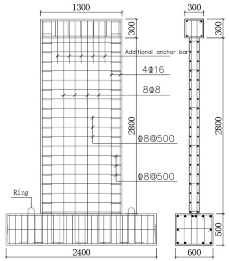
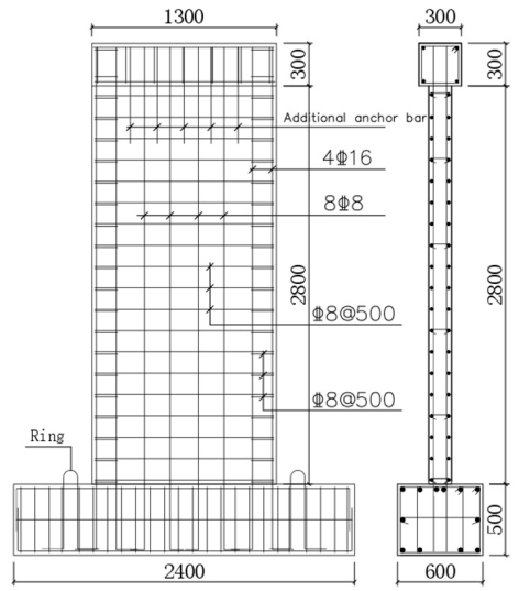
All seven shear-wall specimens employed rectangular sections with identical geometries and reinforcement configurations. Based on related research conducted by experts in the field [31,32,33,34], and considering the test laboratory’s site conditions and the load capacity of the testing apparatus, the wall thickness for each specimen was set to the minimum specification value of 160 mm, the wall height was established to be 2800 mm, and the wall width was determined to be 1300 mm, equating to eight times the wall thickness. Concealed columns were incorporated within 200 mm at both ends of the wall. The wall thickness of 160 mm was adopted because it corresponds to the minimum thickness required for high-grade seismic shear walls in the relevant Chinese design provisions and allowed the actuator and vertical loading frame to cover the intended axial-load range. The reinforcement layout for the test specimen is illustrated in Figure 1, with basic parameters summarized in Table 1.
Figure 1.
Reinforcement of shear-wall specimens. In the reinforcement notation, the symbol “@” denotes the center-to-center spacing of reinforcement bars.
Table 1.
Basic parameters of specimens.
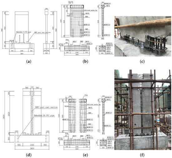
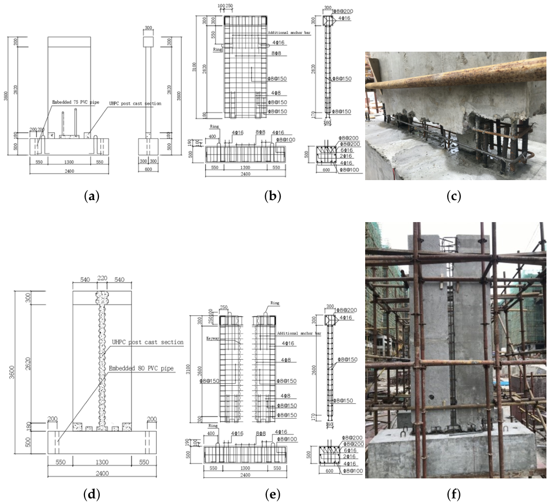
The height of the post-cast UHPC section was designated as follows: 180 mm for the concealed column and 100 mm for the wall limb. Furthermore, to facilitate later handling and splicing, 100 mm-thick concrete legs were added to the bottom of the assembled shear-wall specimen, with a flow-channel width of 60 mm for the UHPC at the legs. The configuration of the specimen’s reinforcing bars and the connection of the reinforcement cross-section are depicted in Figure 2.
Figure 2.
Reinforcement of shear-wall specimens and the testing site: (a) elevation of specimen TW1–TW5; (b) specimen TW1–TW5 reinforcement; (c) detail of the post-cast UHPC section; (d) specimen elevation; (e) specimen TW6 reinforcement; (f) specimen TW6. In the reinforcement notation, the symbol “@” denotes the center-to-center spacing of reinforcement bars.
2.2. Material Properties
The specimen is composed of C40 concrete, while the ultra-high performance concrete (UHPC) is produced using commercial premixed UHPC powder Tenacal T180 (Zhejiang Tenacal New Material Co., Ltd., Ningbo, China). The mix ratios for each group of UHPC are detailed in Table 2. The specimen was constructed by reserving a standard cubic specimen block, which was cured under the same conditions as the structural member. The measured compressive strengths for the concrete and UHPC standard cubic specimens were 46.0 MPa and 110 MPa, respectively. Only compressive strength and elastic modulus were measured in the present wall-test program. Therefore, the interpretation of interface behavior and lap-splice stress transfer is based on wall-level observations and reinforcement strain data, supplemented by previous UHPC bond studies, rather than on direct bond-slip or interface-shear tests in this manuscript.
Table 2.
The proportion of UHPC mix.
To assess the modulus of elasticity, a test was performed on a UHPC prismatic specimen with dimensions of 100 mm × 100 mm × 300 mm, yielding a measured modulus of elasticity (E) of 42.6 GPa. Additionally, the yield strength (fy), yield strain (y), tensile strength (fu), and elongation of each diameter of the reinforcing bar are presented in Table 3. According to the specifications for computing the yield strain of reinforcing bars, the modulus of elasticity for the reinforcement was taken as Es = MPa.
Table 3.
Measured strength of rebars.
2.3. Test Loading Program and Measurement Point Arrangement
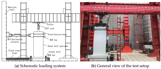
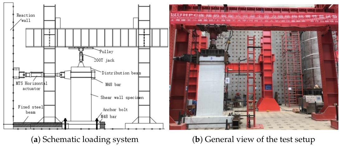
The test was conducted in the structural test laboratory of Henan University of Technology, with the proposed static test loading device illustrated in Figure 3.
Figure 3.
Test setup, including the schematic loading system and a general-view photograph.
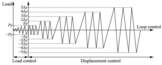
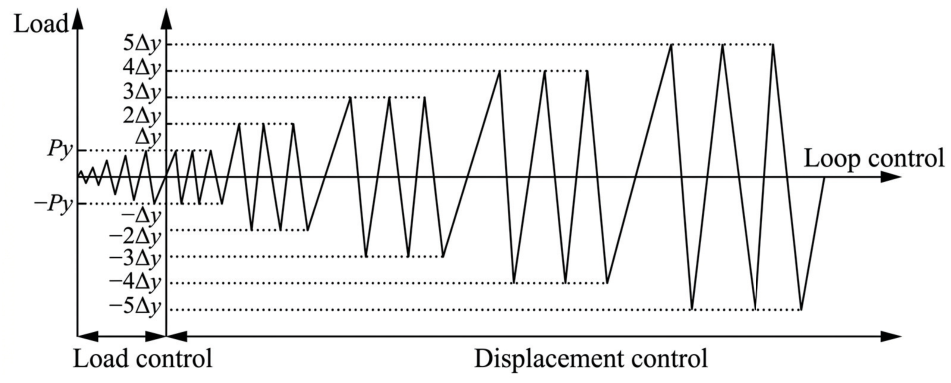
Following the Chinese standard JGJ/T 101-2015 [35] “Specification for Seismic Test of Buildings,” the prescribed vertical axial force for each specimen was applied using a 2000 kN hydraulic jack and was then maintained constant throughout that specimen’s test. The applied axial forces were 660, 660, 1100, 1210, 1560, 1750, and 660 kN for the corresponding specimens listed in Table 1; 2000 kN refers only to the rated capacity of the hydraulic jack, not to the axial force used for every specimen. Subsequently, a reciprocating horizontal force was applied via a 1000 kN actuator. The horizontal loading utilized a hybrid load and displacement control mechanism: it was force-controlled before the specimen yielded, with a load level of 40 kN and one cycle per level. After yielding, the loading switched to displacement control, with an increment equivalent to one times the yield displacement and three cycles per level, until the specimen could no longer sustain the load or the test was halted when the load decreased to 85% of the peak load. The loading system configuration is depicted in Figure 4.
Figure 4.
The loading procedure.
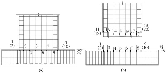
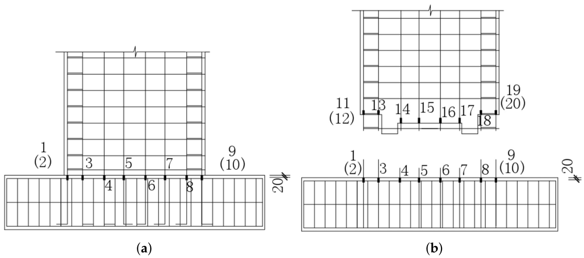
To measure the hysteretic displacement of the shear wall, two tie-wire displacement gauges were positioned at the right end of the loading beam at the same height as the loading point. Additionally, thimble-type displacement gauges were placed along the side of the shear wall at wall heights of 200, 700, 1500, and 2300 mm, with two tie-wire displacement gauges arranged diagonally along the front of the shear wall. To monitor the translation, rotation, and buckling of the floor beams, three displacement gauges were installed on both sides of the beams. Strain gauges were employed to measure the reinforcement strains; these were positioned 20 mm from the top surface of the beam in specimen SW, while in specimens TW1 to TW6, they were arranged 20 mm from the ends of the overlapped bars to investigate the force transmission performance of the new connection. The configuration of the strain gauges on the reinforcement is illustrated in Figure 5.
Figure 5.
Arrangements of strain gauges: (a) specimen SW strain gauge arrangement; (b) specimen TW1–TW5 gauge arrangement. Numbers without brackets denote strain gauges on the front side of the reinforcement, whereas numbers in brackets denote the corresponding strain gauges on the opposite side.
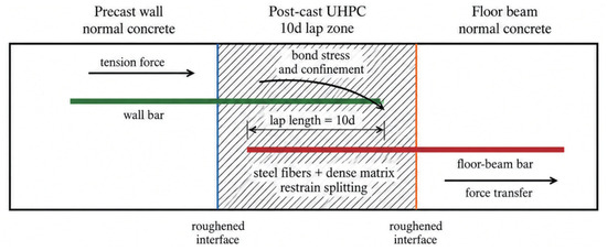
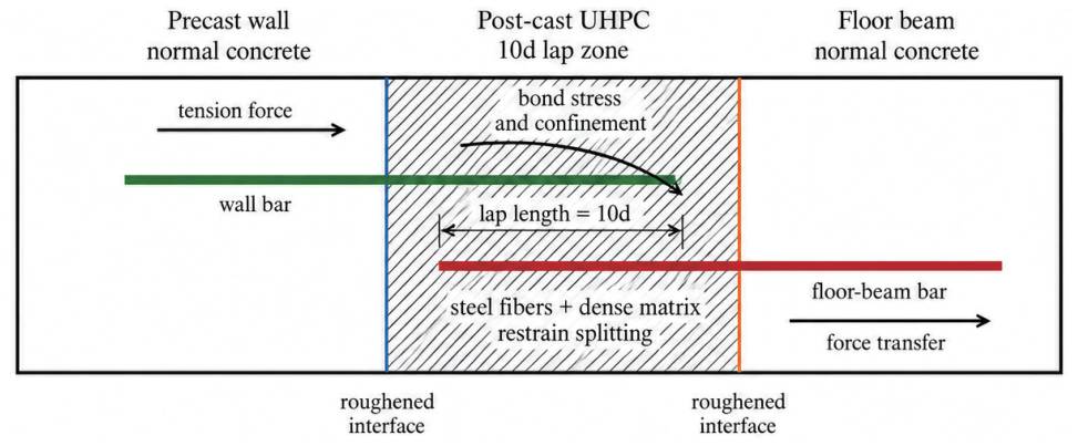
The expected force-transfer mechanism of the proposed connection is illustrated in Figure 6. In the horizontal UHPC back-cast zone, tensile force in the wall vertical reinforcement is transferred to the lapped reinforcement through bond stress along the steel-UHPC interface. The steel fibers and dense UHPC matrix provide confinement around the short lap and delay splitting. At the UHPC-normal concrete interface, roughened contact surfaces and bearing/friction transfer shear and compression. The wall tests can reveal the global consequence of these mechanisms through cracking, reinforcement strain, and hysteresis response, but they do not provide a direct local measurement of bond slip or interface slip.
Figure 6.
Schematic force-transfer mechanism in the post-cast UHPC lap zone.
3. Test Phenomenon and Damage Pattern
3.1. Test Phenomenon
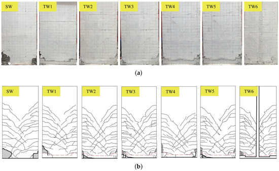
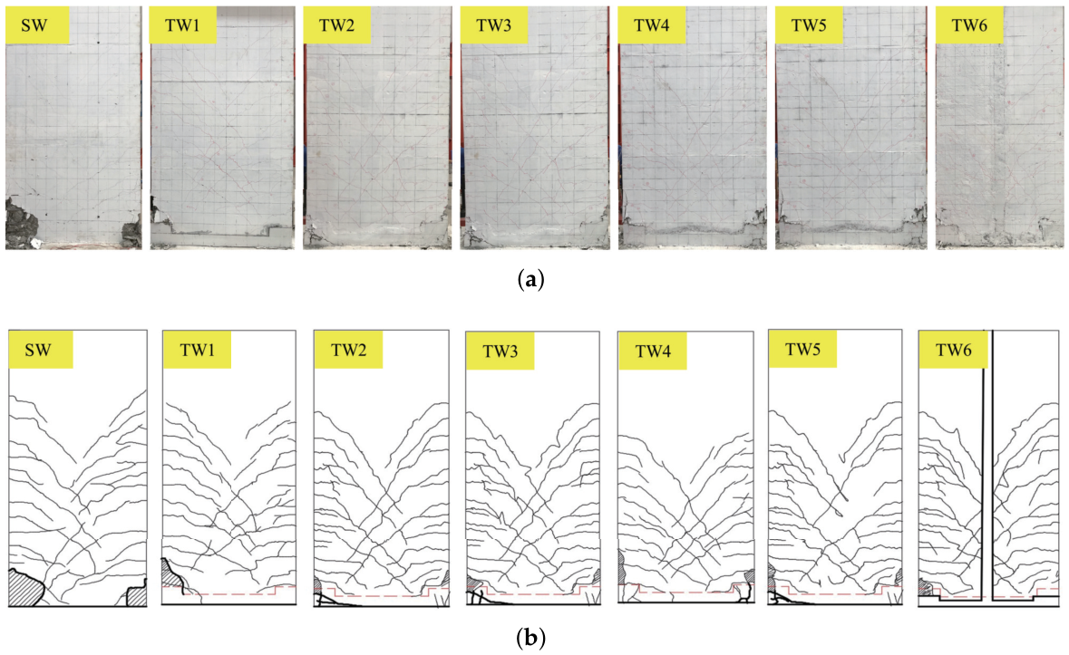
All specimens exhibited similar crack development stages: initial flexural cracks at the wall base, followed by diagonal shear cracks, and finally crushing of concrete in the compression zone with yielding of the vertical reinforcement. However, noticeable differences were observed among specimens with different joint configurations and axial compression ratios. The final crack distributions are shown in Figure 7.
Figure 7.
Distribution of cracks after failure: (a) post-failure photographs; (b) crack distribution maps. the red dashed line denotes the UHPC–precast concrete construction joint seam, which indicates the original connection boundary and is distinguished from the loading-induced cracks in the crack maps.
For clarity, the lines corresponding to the UHPC–precast concrete boundaries in Figure 7b indicate construction joint seams formed by the post-cast connection detail. These seams existed before loading and should not be interpreted directly as newly generated cracks. In the following discussion, they are treated as cracks only when visible opening, extension, or widening was observed during cyclic loading.
Monolithic specimen SW: The first horizontal crack appeared at 160 kN (tensile side). At 280 kN, shear cracks formed an “X” pattern and the concealed-column reinforcement yielded. Failure occurred at mm (third cycle) with extensive concrete spalling at both ends and outward bulging of compression reinforcement.
Specimens with horizontal joints (TW1–TW5): Their damage patterns were generally similar to SW, but the crushed concrete zone shifted upward, occurring above the UHPC back-cast area rather than at the wall bottom. For the non-defective specimens, increasing axial compression ratio generally increased cracking and peak loads (see Table 4); however, this trend should be interpreted cautiously because no repeat specimens were tested. TW2 (axial compression ratio 0.30) is treated in the following discussion as a construction-quality-sensitive specimen rather than as an ordinary member of the axial-compression-ratio series. Its left UHPC protective layer was locally thinner than the design value of 15 mm because of casting deviation, which led to local splitting failure on the tensile side at and deteriorated its hysteresis and energy dissipation.
Table 4.
Horizontal forces of characteristic points for specimens.
Specimen with vertical joints (TW6): The UHPC vertical and horizontal post-cast zones helped the two half-walls work together during most loading stages, but the response of TW6 cannot be interpreted as the isolated effect of the vertical joint because the specimen also contained a bottom horizontal joint and two half-wall panels. In-plane lateral slippage (≈3 mm) occurred at the beam–wall joint. The tensile vertical bars were sheared off at failure, and the ultimate displacement angle exceeded 1/100, meeting the seismic code requirement.
3.2. Damage Pattern
The damage patterns of specimens SW and TW1–TW5 were primarily characterized by compression-bending damage: yielding of the vertical reinforcement in the concealed columns and compression collapse of the concrete at the bottom. A notable difference is that for the assembled specimens (TW1–TW5) the concrete crushing zone shifted upward, occurring above the UHPC back-cast area instead of at the very bottom of the wall. This upward shift indicates that the UHPC zone remained comparatively intact in most specimens, while the adjacent normal concrete became the critical compression region.
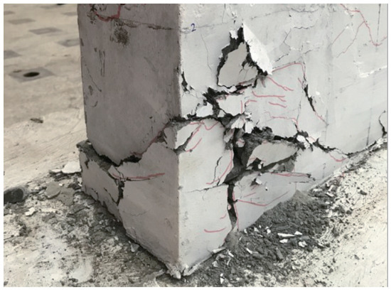
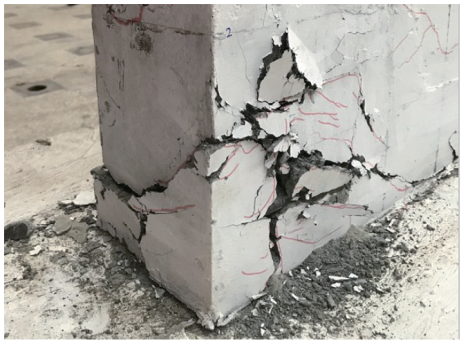
In contrast, specimen TW6 exhibited bending-shear damage. The UHPC connections enhanced the integrity of the two half-walls, but the back-cast zone became the weak point. This observation indicates that the joint region should be regarded as a reliability-critical region rather than as a fully verified ductile energy-dissipation region. Additionally, due to a casting defect, specimen TW2 had an insufficient UHPC protective layer (<15 mm) on the left side, which caused local splitting failure under high tensile stress, as shown in Figure 8.
Figure 8.
UHPC at the bottom of specimen TW2 after failure.
4. Results and Discussion
4.1. Hysteresis Curve
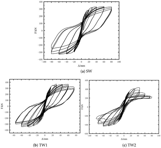
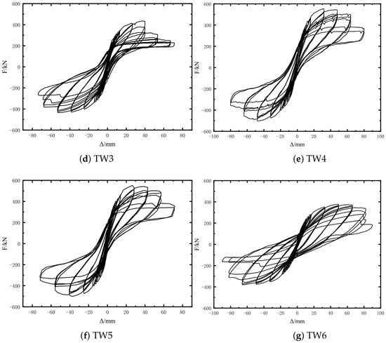
The hysteresis curves of shear-wall specimens are illustrated in Figure 9, which reveals the following observations:
Figure 9.
Hysteretic curves of specimens.
- (1)
- When specimens SW, TW1, and TW6 have the same axial compression ratio, their hysteresis performance is generally similar. The hysteresis curves appear full, exhibiting no notable “pinching” phenomenon. After reaching the peak load, as the displacement increases, the load is sustained for a period before gradually declining, demonstrating good post-peak load-retention capacity.
- (2)
- Specimens TW1, TW2, TW3, TW4, and TW5 share the same assembly structure, with axial pressure ratios of 0.2, 0.3, 0.33, 0.45, and 0.47, respectively. As the axial pressure ratio increases, the hysteresis curves display significant “pinching,” with more pronounced effects at higher axial pressure ratios. The phenomenon of pinching becomes increasingly evident with rising axial pressure ratios, which correlates with the cracking and localized collapse of the concrete. With an elevated axial pressure ratio, the development of cracks is inhibited, leading to a diminished deformation capacity. TW2 is not used as the sole basis for the axial-compression-ratio trend because its construction defect introduced an additional confounding factor.
- (3)
- Notably, the hysteresis curve of specimen TW2 experiences a sharp decline at a horizontal load corresponding to a displacement of 3y. This abrupt decrease is attributed to localized splitting damage of the UHPC section on the tensile side at this load level, which compromises the grip of the vertical reinforcement within the UHPC and adversely affects the hysteresis performance of the specimen.
4.2. Skeleton Curves
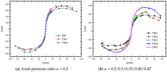
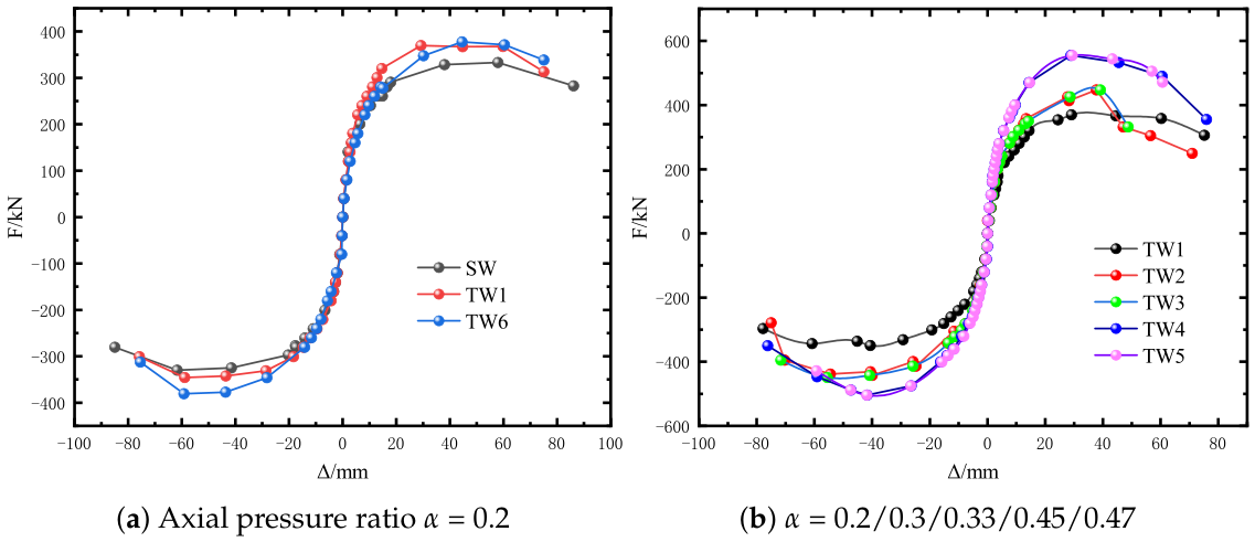
The skeleton curves for the two comparison groups of specimens are presented in Figure 10. The skeleton curves of the assembled specimen and the full-cast specimen exhibit essentially the same trend: during the initial loading phase, the curves are linear, indicating that the specimens are in the elastic stage. After the shear wall experiences cracking, some of the concrete becomes disengaged from the load-bearing function, leading to a noticeable degradation in specimen stiffness as it transitions into the elastic–plastic stage. As the horizontal force continues to increase to the peak load, the reinforcement undergoes plastic deformation, further contributing to the withdrawal of concrete from the load-bearing role, and the curves eventually enter the descending section until the specimen fails.
Figure 10.
Comparisons of skeleton curves.
4.3. Carrying Capacity
Table 4 lists the bearing capacities of the seven-bay shear-wall specimens at key stages. The nominal yield point was determined from the skeleton curve using the energy-equivalent method. Specifically, the experimental skeleton curve was idealized as a bilinear curve; the yield point was adjusted so that the area enclosed by the idealized bilinear curve up to the peak state was equal to the corresponding area under the experimental skeleton curve. The resulting yield force and yield displacement are reported as and . It is evident that the cracking loads and peak loads of assembly specimens TW1 and TW6 are slightly higher than those of the full-cast specimen SW under an axial compression ratio of 0.2. This comparison is made only for specimens with the same axial compression ratio and should not be interpreted as proof that all UHPC-jointed walls are superior to cast-in-place walls. This can be attributed to the following factors:
- (1)
- The greater strength of the UHPC in the back-cast zone at the bottom of the assembled specimens TW1 and TW6 provides localized reinforcement for the vertical reinforcement and vertical distribution bars in the lap zone.
- (2)
- The casting orientation also influenced the comparison. The precast walls of specimens TW1 and TW6 were cast horizontally, whereas the full-cast wall SW was cast vertically, resulting in relatively poor concrete densities. Therefore, the observed capacity increase cannot be attributed solely to the UHPC connection. Additionally, the assembled specimens TW1, TW2, TW3, TW4, and TW5, which featured horizontal joints at the wall base, demonstrated a significant increase in bearing capacity with rising axial compression ratios except that TW2 is discussed separately because of the UHPC-cover defect.
4.4. Deformability
We define the vertex displacement angle , where represents the horizontal displacement at the loading point of the specimen, and H is the distance from the loading point to the top surface of the floor beam, with mm. The deformation capacity of the specimen is characterized by the displacement ductility coefficient , where is the horizontal displacement corresponding to the specimen at destructive load, and is the nominal yield displacement. Table 5 provides the displacements of the seven-bay specimens across different stages. For the code-oriented performance discussion, the ultimate drift ratio is evaluated together with the observed failure mode, stiffness degradation, energy dissipation, and connection damage. The drift ratio greater than 1/100 indicates satisfactory deformation capacity for the tested specimens, but TW2 and TW6 show that construction quality and vertical-joint detailing remain important reliability issues. We note the following:
Table 5.
Displacement of characteristic points for specimens.
- (1)
- The difference between the displacement ductility coefficients of specimens TW1 and SW is not substantial when the axial compression ratios are equal.
- (2)
- The displacement ductility coefficient of specimen TW6 is approximately 73% of that of the full-cast specimen, attributed to the presence of vertical joints that inhibit the development of cracks in the shear wall, thereby enhancing specimen integrity but reducing deformation capacity.
- (3)
- Specimen TW2 exhibits the smallest displacement ductility coefficient and the poorest deformation capacity due to localized splitting damage on the bottom UHPC side, which adversely impacts the overall deformation of the specimen.
4.5. Stiffness Degradation
The stiffness of the specimen can be characterized by the cyclic stiffness, as expressed in Equation (1):
where is the cyclic stiffness at the i-th displacement level; and are the positive and negative peak loads in the j-th cycle at that level, respectively; and are the corresponding positive and negative peak displacements; and n is the number of cycles at that displacement level. Absolute values are used so that the positive and negative contributions are summed consistently.
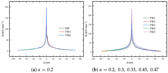
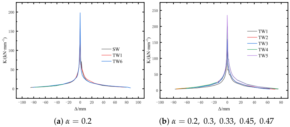
Figure 11 presents a comparison of the stiffness curves for the specimens. The following observations can be made:
Figure 11.
Stiffness degradation curves of specimens: (a) axial pressure ratio ; (b) axial pressure ratios , , , , .
- (1)
- The stiffness degradation behavior of the assembled specimen is fundamentally similar to that of the full-cast specimen. Stiffness degradation occurs more rapidly before cracking, with the rate of degradation slowing down after the specimen has cracked. Near the destructive load, the stiffness of both specimens converges to a similar value.
- (2)
- The initial stiffness of specimen TW6 is greater; however, due to overall lateral movement, its stiffness aligns closely with that of the full-cast specimen at the point of failure.
4.6. Reinforcement Strain
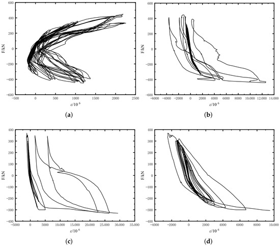
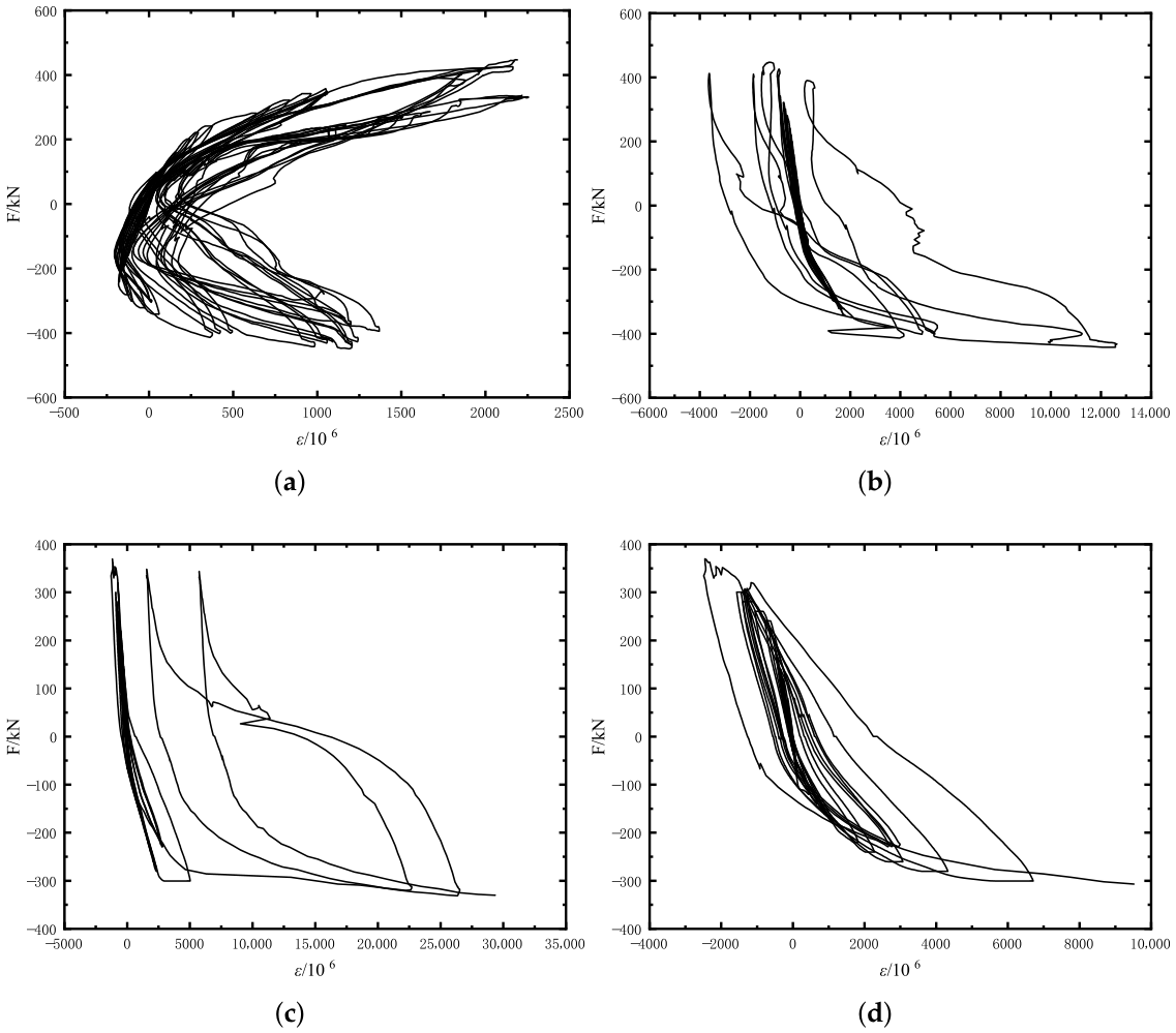
The load–strain (F-) curves for several measured points are presented in Figure 12. The strain gauges installed in multiple bays of the assembled specimens exhibited similar behaviors. The strains recorded for the same vertical reinforcement connected to the post-cast section at the concealed columns of specimens TW1 and TW3 are listed. Figure 12a,b, as well as Figure 12c,d, illustrate the measurement points for the same vertical reinforcement within the wall and floor beams of the UHPC post-cast section, respectively:
Figure 12.
Load–strain curves of strain gauges: (a) specimen TW1 strain gauge 1; (b) specimen TW1 strain gauge 11; (c) specimen TW3 strain gauge 10; (d) specimen TW3 strain gauge 20.
- (1)
- Prior to the yielding of the reinforcement, the strain growth rate is slow while the specimen is in the elastic stage. Following yielding, the strain of the reinforcement increases rapidly, and the trends of the two curves are similar. The similar strain development on the lapped bars suggests that the UHPC post-cast zone and the 10d lap splice participated in stress transfer in the tested specimens. However, this evidence is indirect because no local bond-slip gauges or interface-slip transducers were installed.
- (2)
- Before global failure, the global displacement and reinforcement strain records did not show evidence of abrupt bar pull-out. Therefore, the anchorage performance can be described as adequate for the tested specimens, while a complete bond-transfer assessment requires dedicated bond-slip or local-slip measurements.
- (3)
- The hysteresis curve of the strain gauge within the floor beam is relatively fuller, attributed to the greater strength of UHPC, which maintains better integrity after the specimen yields. Additionally, no obvious cracks are observed at the bottom, which helps inhibit deformation of the reinforcement.
4.7. Energy Dissipation Capacity
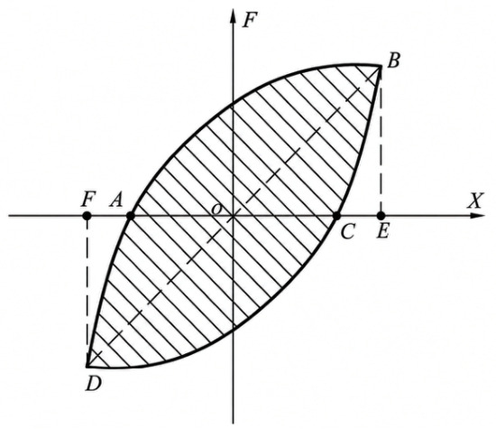
According to JGJ/T 101-2015 [35], the energy dissipation coefficient E was used to quantify the energy dissipation capacity of the specimens. The schematic definition of the energy dissipation coefficient is shown in Figure 13. For a selected hysteresis loop, the enclosed hysteretic area represents the energy dissipated during one loading cycle, while the triangular areas associated with the positive and negative peak points are used as the reference elastic potential-energy terms.
Figure 13.
Schematic definition of the energy dissipation coefficient.
Accordingly, the energy dissipation coefficient E is calculated as
where denotes the area enclosed by the hysteresis loop, and denotes the sum of the two reference triangular areas formed by the positive and negative peak points of the same loop. A larger value of E indicates stronger energy dissipation capacity.
The calculated results are summarized in Table 6. It can be observed that, when the axial compression ratio is the same, i.e., 0.2, the energy dissipation coefficients of the assembled specimens TW1 and TW6 are greater than 90% of that of the cast-in-place specimen SW. This indicates that the assembled shear walls exhibit energy dissipation capacities comparable to that of the cast-in-place specimen under the same axial compression ratio.
Table 6.
Energy dissipation ratios of specimens.
Examining specimens TW1 to TW5 with varying axial pressure ratios reveals that specimen TW2, which has an axial pressure ratio of 0.30, exhibits the smallest E value corresponding to the ultimate load and the worst energy dissipation capacity. TW2 is interpreted as a workmanship-sensitivity case rather than a normal data point for the axial-compression-ratio trend. This is attributed to localized damage in the UHPC at the bottom of the tensile side at , which severely pinches the hysteresis loop in the forward direction, leading to a further deterioration in the overall energy dissipation capacity of the specimen; as a result, the E value is lower than that of specimen TW3, which has a higher axial pressure ratio.
4.8. Mechanical Interpretation, Joint Reliability, and Applicability
The proposed post-cast UHPC connection should be interpreted as a capacity-protected connection rather than as a ductile weak link intentionally used for energy dissipation. The design intention is that the UHPC lap zone provides sufficient bond transfer and confinement so that the main damage is shifted to the adjacent normal concrete wall region. This interpretation is consistent with the observed upward shift of the concrete crushing zone in most specimens with horizontal UHPC joints. Nevertheless, the interface cracking shown in Figure 7 and the workmanship-sensitive damage of TW2 demonstrate that the joint region remains critical for structural reliability and construction quality control.
For a simplified bond-transfer interpretation, the tensile force that can be transferred by a lapped bar through bond action may be expressed as
where is the bond-transfer resistance of the lapped bar, is the bar diameter, is the lap length, and is the average ultimate bond stress between UHPC and reinforcement. To develop the yield force of the reinforcement, the following condition is required:
where and are the area and yield strength of the reinforcement, respectively. This expression is used here only as a mechanistic explanation rather than as a calibrated design equation, because no local bond-slip tests were conducted in the present wall-test program. Compared with normal concrete, UHPC can increase through its denser matrix, higher tensile resistance, and fiber confinement, thereby allowing the lap length to be shortened. If normal concrete were used in the same post-cast region, conventional reinforced-concrete lap-splice requirements would require a much longer lap length, approximately 35d, which would increase the post-cast length, reduce the prefabricated proportion of the wall segment, and increase the difficulty of formwork erection and on-site casting.
The shear transfer along the UHPC–normal concrete interface can also be described conceptually as
where is the total interface shear-transfer capacity, or represents the adhesive contribution of the interface, or represents friction under normal compression, represents the mechanical interlock of the roughened interface, and represents the dowel contribution of reinforcement crossing or adjacent to the interface. This model explains the expected shear-transfer mechanism of the roughened interface, but the individual terms were not quantified in this study because no independent interface direct-shear test or interface-slip transducer was included.
The present results therefore support only a tested-configuration-level assessment of the proposed UHPC short-lap connection. Although the cyclic tests involved load reversal and tensile demand in the wall boundary reinforcement, they do not cover all tensile-dominant or dynamic demands that may occur in high-seismic regions. Engineering use in high-seismic zones should be supported by further tests on local bond slip, joint opening, interface cyclic shear, repeated specimens, normal-concrete post-cast controls, and dynamic or pseudo-dynamic loading.
5. Conclusions
The conclusions drawn from the proposed quasi-static cyclic tests of six assembled shear walls connected with post-cast UHPC, along with one full-cast shear wall, are as follows:
- (1)
- The specimen with horizontal joints at the bottom of the wall exhibited a damage pattern similar to that of the full-cast specimen, characterized by compression-flexure-dominated damage. Upon failure, the vertical reinforcement of the concealed column yielded, and the concrete at the bottom was crushed. In contrast, the specimen with a vertical joint in the middle of the wall demonstrated bending and shearing damage, with part of the vertical reinforcement of the concealed column shearing off. Within the present test range, the axial compression ratio mainly affected cracking distribution, bearing capacity, and deformation capacity; its influence on the final global failure mode was less pronounced than the influence of joint configuration and local construction quality.
- (2)
- For the specimens tested at an axial compression ratio of 0.20, TW1 and TW6 had slightly higher peak loads than SW, while their ductility and energy-dissipation indices remained in a comparable range. This result is affected by both the UHPC joint and the different casting orientations of the specimens, so it should not be generalized as a universal capacity advantage of all assembled walls.
- (3)
- The reinforcement strain records and absence of abrupt bar pull-out before global failure suggest that the 10d short lap with post-cast UHPC provided adequate stress transfer in the tested specimens. This conclusion is limited by the absence of direct bond-slip and interface-slip measurements. The ultimate drift ratios exceeded 1/100; together with the observed failure modes, stiffness degradation, and energy-dissipation indices, this indicates acceptable seismic deformation capacity for the tested configurations.
- (4)
- Visual cracking showed that the UHPC-floor-beam interface was a relatively vulnerable region in several specimens, with cracks tending to develop along the roughened interface. Because no direct interface shear or quantified roughness tests were conducted, this observation should be interpreted as an experimental cracking tendency rather than a quantified statement of weak bond strength. The shaped interface between the precast wall and the UHPC appeared to improve crack distribution compared with a straight horizontal interface, but further interface testing is required.
6. Future Research
To further promote the assembled shear wall structure based on UHPC material, it is recommended to conduct the following research initiatives. These recommendations are particularly important because the present program contained one vertical-joint specimen and no repeated specimens.
- (1)
- To prevent premature cracking at the joints between UHPC and precast concrete, additional in-depth research and testing should be performed on the interface treatment between UHPC and ordinary concrete.
- (2)
- When implementing this new type of connection in actual projects, the shear capacity of the shear walls can be enhanced by incorporating shear-resisting keys and other mechanisms.
- (3)
- Further investigations should be conducted to examine the influence of the thickness of the protective layer of UHPC at concealed columns on the seismic performance of the shear walls.
- (4)
- Comparative specimens with normal-concrete post-cast zones should be tested to quantify how the longer lap length required in normal concrete changes the force-transfer mechanism, construction efficiency, and seismic response.
- (5)
- For application in high-seismic regions, additional validation should include interface cyclic-shear tests, local bond-slip and joint-opening measurements, repeated wall specimens, and dynamic or pseudo-dynamic loading protocols.
Author Contributions
Conceptualization, G.C. and S.Y.; methodology, G.C. and S.Y.; formal analysis and investigation, S.Y.; writing—original draft preparation, G.C., S.Y. and L.L.; writing—review and editing, G.C., S.Y., Q.Z., D.N. and H.L.; funding acquisition, Q.Z. and G.C.; resources, H.L. and L.L.; supervision, Q.Z. and G.C. All authors have read and agreed to the published version of the manuscript.
Funding
This research was funded by the National Natural Science Foundation of China, grant number 51978401, and the Scientific Research Program Project of Shanghai Municipal Science and Technology Commission, grant number 17DZ1203503.
Data Availability Statement
The datasets generated during the current study are available from the corresponding author upon reasonable request.
Conflicts of Interest
Author Libo Long was employed by the company Shanghai Construction No. 2 (Group) Co., Ltd. The remaining authors declare that the research was conducted in the absence of any commercial or financial relationships that could be construed as a potential conflict of interest.
Abbreviations
| UHPC | Ultra-high performance concrete |
| SW | Cast-in-place control specimen |
| TW | Assembled shear-wall specimen |
References
- JGJ 1-2014; Technical Specification for Precast Concrete Structures. China Architecture & Building Press: Beijing, China, 2014.
- Qin, C.G.; Gao, Z.Y.; Yang, L.; Wu, T. Study on shear resistance of precast concrete sleeve grouting joint with double interface. J. Build. Struct. 2024, 45, 223–235. [Google Scholar] [CrossRef]
- Qian, J.R.; Yang, X.K.; Qin, H.; Peng, Y.Y.; Zhang, J.M.; Li, J.S. Tests on seismic behavior of pre-cast shear walls with various methods of vertical reinforcement splicing. J. Build. Struct. 2011, 32, 51–59. [Google Scholar]
- Zhao, J.H.; Ling, L.J.; Wan, L.; Wang, C.; Liu, Z.J.; Wang, T. Experimental study on strength of grouting materials for sleeve grouting of prefabricated concrete structures. China Concr. Cem. Prod. 2023, 75–79. [Google Scholar]
- Yu, Q.; Tang, Z.M.; Zhang, X.K.; Fan, B.X.; Zhang, Z.; Chen, Z.H. Test on seismic behavior of L-shaped precast shear wall with grouted sleeve lapping connector. J. Harbin Inst. Technol. 2023, 55, 72–83. [Google Scholar]
- Lu, Z.W.; Wu, B.; Sakata, H.; Huang, J.; Zhang, M.Z. Mechanical performance of prefabricated concrete beam-column joints with double-grouted sleeve connectors: A numerical and theoretical study. Structures 2023, 56, 104870. [Google Scholar]
- Qian, F.; Zheng, S.C.; Wang, Y.; Xiang, H.W.; Wang, Y.F.; Xu, R.Q. Failure mechanism analysis and partial-interaction numerical simulation of Grouted Sleeve Connections (GSC) in tensile behavior. Case Stud. Constr. Mater. 2024, 20, e03040. [Google Scholar] [CrossRef] [Scilit]
- Huang, E.H.; Lin, P.; Wang, C.L. Seismic experimental study of prefabricated columns with slurry-anchor lap connection. Sichuan Build. Mater. 2019, 45, 94–95. [Google Scholar]
- Qian, J.R.; Peng, Y.Y.; Zhang, J.M.; Qin, H.; Li, J.S.; Liu, G.Q.; Zhao, F.D.; Li, L.R. Tests on seismic behavior of pre-cast shear walls with vertical reinforcements spliced by grout sleeves. Build. Struct. 2011, 41, 1–6. [Google Scholar]
- Ma, C.F.; Jiang, H.B.; Zhang, Z.B.; Cao, Z. Ultrasonic testing on grouting plumpness of prefabricated concrete shear wall restraint grouting-anchoring overlap-joint. Concrete 2020, 132–136+140. [Google Scholar]
- Wang, C.L.; Song, M.M. Seismic performance of slurry anchor lapping of corrugated pipe restrained by spiral stirrup. Ind. Constr. 2021, 51, 126–131. [Google Scholar]
- Zhong, Z.L.; Li, G.F.; Shi, S.H.; Zhao, M.; Du, X.L. Experimental study on out-of-plane seismic performance of sidewall connections of utility tunnels with composite plates. Eng. Mech. 2024, 41, 39–49+105. [Google Scholar]
- Wan, L.J.; Zhao, Y.Q.; Yu, M.P.; Li, N.; Sun, X.L. Experimental study on spatial mechanical properties of grout anchor lap joints. Structures 2022, 44, 728–739. [Google Scholar] [CrossRef] [Scilit]
- Chen, J.W.; Su, Y.P. Prefabricated concrete shear wall structure and its connecting technology. World Earthq. Eng. 2013, 29, 38–48. [Google Scholar]
- Xue, W.C.; Hu, X. Overview of research progress on precast concrete building structure system. Constr. Technol. 2018, 47, 1–5+43. [Google Scholar]
- Li, G.; Huang, X.K.; Liu, X.; Li, Z.L.; Li, R.; Tian, C.Y.; Liu, S.M. Experimental study on seismic behavior of monolithic precast concrete shear wall with rebar overlapped in pre-reserved area for subsequent concrete casting. J. Build. Struct. 2016, 37, 193–200. [Google Scholar]
- Yang, Y. Experimental Research on Seismic Performance of Precast Shear Wall with Vertical Joint Surface. Master’s Thesis, Harbin Institute of Technology, Harbin, China, 2011. [Google Scholar]
- Gu, Q.; Dong, G.; Wang, X.; Jiang, H.B.; Peng, S.M. Research on pseudo-static cyclic tests of precast concrete shear walls with vertical rebar lapping in grout-filled constrained hole. Eng. Struct. 2019, 189, 396–410. [Google Scholar]
- Ding, W.S.; Wang, Y.Z.; Nie, Z.L.; Wang, T.; Yang, S. Experimental study on shear behavior of UHPC-T beams. J. Technol. 2024, 24, 55–62. [Google Scholar]
- Huang, Y.; Xia, W.L.; Hong, Z.C. Experimental and theoretical model study on shear performance of ultra-high performance concrete corbels. J. Build. Struct. 2024, 45, 108–117. [Google Scholar]
- Liu, R.C.; Dong, E.L.; Ma, X.W.; Song, S.M. Research progress on shrinkage of ultra high performance concrete. Build. Struct. 2024, 54, 91–98. [Google Scholar]
- Zheng, Q.Z.; Rang, M.; Li, P. Experimental study on the bond behavior between ultra-high performance concrete and steel bars. J. Univ. Shanghai Sci. Technol. 2018, 40, 398–402. [Google Scholar]
- Wang, R.L.; Ma, B. Study on bond anchorage test of steel bar and ultrahigh performance concrete. Urban Roads Bridg. Flood Control 2018, 204–207+22–23. [Google Scholar]
- Farzad, M.; Azizinamini, A. Experimental and numerical study on Mechanical Properties of Ultra High Performance concrete (UHPC). Constr. Build. Mater. 2017, 156, 402–411. [Google Scholar] [CrossRef] [Scilit]
- Wu, C.; Hwang, H.J.; Ma, G. Bond Strength of Tension Lap Splices in Pre-Damaged Reinforced Concrete Beams Retrofitted with Carbon Fiber- Reinforced Polymer and Ultra-High-Performance Concrete. ACI Struct. J. 2023, 120, 103–118. [Google Scholar]
- Li, T.; Nie, Z.; Wang, S.Q.; Long, L.B.; Ma, Y.Q. Research on the corrosion resistance and mechanical properties of the bonding surface between ultra-high performance concrete and normal concrete. China Concr. Cem. Prod. 2024, 10–15+21. [Google Scholar]
- Dapper, P.R.; Ehrendring, H.Z.; Pacheco, F.; Christ, R.; Menegussi, G.C.; Oliveira, M.F.; Tutikian, B.F. Ballistic Impact Resistance of UHPC Plates Made with Hybrid Fibers and Low Binder Content. Sustainability 2021, 13, 13410. [Google Scholar] [CrossRef] [Scilit]
- Zahid, M.Z.A.M.; Bakar, B.H.A.; Nazri, F.M.; Alasmari, H.; Latiff, M.F.P.M.; Ayob, A.; Muhammad, K.; Ahmad, M.M.; Manaf, B.H.A.; Ishak, M.K. Mechanical, Durability and Rheology Properties of Ultra High Performance Concrete (UHPC) with Low Cement Content. IOP Conf. Ser. Earth Environ. Sci. 2021, 920, 012005. [Google Scholar] [CrossRef] [Scilit]
- Khan, M.I.; Fares, G.; Abbas, Y.M.; Alqahtani, F.K. Behavior of Non-Shear-Strengthened UHPC Beams under Flexural Loading: Influence of Reinforcement Percentage. Appl. Sci. 2021, 11, 11346. [Google Scholar]
- Li, P.; Zheng, Q.Z.; Long, L.B.; Chen, G. Effect of rebar embedment length on the bond behavior between ultra-high performance concrete and reinforcing bars. Build. Constr. 2016, 38, 1722–1723+1729. [Google Scholar]
- Liu, X.H.; Zheng, S.S.; Wang, W.; Liu, H.; Zheng, Y.; Zheng, H. Experimental study on the seismic behaviour of a corroded T-shaped RC shear wall. J. Build. Eng. 2023, 76, 107071. [Google Scholar] [CrossRef] [Scilit]
- Xu, Z.F.; Chen, Z.F.; Dong, X.T.; Zuo, Y.N. Experimental Study on Seismic Behavior of Lightweight Concrete-Filled Cold-Formed Steel Shear Walls Strengthened Using Horizontal Reinforcement. J. Earthq. Eng. 2023, 27, 4126–4160. [Google Scholar]
- Zhang, X.Z.; Lang, D.S.; Chen, J.J.; Niu, S.X.; Zhang, J.W. Seismic performance research on prefabricated RC shear walls with cast-in-place wedge-shaped joint connection. Build. Struct. 2017, 47, 75–81+88. [Google Scholar]
- Zhao, C.H.; Li, H.D.; Deng, K.L. Experimental Study on Bonding Performance Between Rebar and Coarse Aggregate Ultra-High Performance Concrete. J. Southwest Jiaotong Univ. 2019, 54, 937–944. [Google Scholar]
- JGJ/T 101-2015; Specification for Seismic Test of Buildings. China Architecture & Building Press: Beijing, China, 2015.

Disclaimer/Publisher’s Note: The statements, opinions and data contained in all publications are solely those of the individual author(s) and contributor(s) and not of MDPI and/or the editor(s). MDPI and/or the editor(s) disclaim responsibility for any injury to people or property resulting from any ideas, methods, instructions or products referred to in the content. |
© 2026 by the authors. Licensee MDPI, Basel, Switzerland. This article is an open access article distributed under the terms and conditions of the Creative Commons Attribution (CC BY) license.