


Abstract
In reinforced concrete structures, the primary and secondary beam joints are capable of transferring concentrated loads through additional transverse reinforcement, such as additional stirrups or additional hanging reinforcement. Ensuring the structural safety of these joints under situations such as small height differences between the primary and secondary beams, large secondary beam loads, or marine environments is crucial. Current research mainly focuses on the structural safety of individual structural members or conventional frame joints. Studies on primary and secondary beam joints are limited, and the performance of additional hanging reinforcement under special situations has been neglected. This study identifies two special situations at primary and secondary beam joints—the “small height difference” and the “large load”—and verifies their rationality through numerical simulations. Furthermore, an ultimate bearing capacity degradation ratio is introduced to quantify the effect of reinforcement corrosion on the mechanical performance of these joints. The results demonstrate that, without considering reinforcement corrosion, beams with additional stirrups fail to satisfy the ultimate bearing capacity requirements under the “small height difference” and “large load” situations. In such cases, additional hanging reinforcement should be adopted as the reinforcement mode. When reinforcement corrosion is considered, the ultimate bearing capacity degradation ratio of the beam with additional stirrups drops to approximately 0.65 after 30 years of service, whereas that of the beam with additional hanging reinforcement remains above 0.95. Under these situations, additional hanging reinforcement is even more preferable. This study clarifies the selection principle for primary and secondary beam joint additional transverse reinforcement under the two special situations and corrosion environments. The research findings provide guidance and reference for the structural design of reinforced concrete primary and secondary beam joints.
1. Introduction
With the rapid development of urban construction and the growing demand for diversified architectural functions, the forms of reinforced concrete structures have become increasingly diversified and complex [1,2]. The vertical extension and planar expansion of building usage space have raised requirements for the span and section dimension of structural beam systems, prompting the widespread adoption of deeper primary beams and even secondary beams in practical engineering. Consequently, a large number of primary and secondary beam joints are extensively arranged in both above-ground and underground structures [3,4,5]. Primary and secondary beam joints serve as the critical load-transfer hubs, transmitting the concentrated loads from secondary beams to primary beams. Their mechanical performance directly determines the bearing capacity and overall structural stability, playing a vital controlling role in the main structure of the buildings and underground facilities such as foundation pits, underground garages, and tunnel auxiliary structures. Located at intersections and stress-rich regions of the primary and secondary beams, these joints bear the concentrated loads transferred from secondary beams, which induce significant local compressive stress within the joint region. Once the stress exceeds the local compressive strength of concrete, detrimental damage such as cracking at the bottom of primary beams, surface spalling, and even local compression failure is highly likely to occur [6,7,8]. Underground structures, subjected to coupled effects of water–earth pressure, stratum constraints, and groundwater fluctuations, experience even harsher stress environments and higher damage risks at the joints [9,10]. Therefore, to effectively improve local compressive performance and the crack resistance of concrete at primary and secondary beam joints, it is essential to rationally arrange additional transverse reinforcements in the joint region for structural strengthening.
Additional transverse reinforcement at primary and secondary beam joints primarily functions to bear the concentrated loads transferred from secondary to primary beams. According to the Code for Design of Concrete Structures (GB 50010-2010) [11], concentrated loads acting at the beam bottom or within the beam section depth shall be entirely undertaken by additional transverse reinforcement, among which additional stirrups are commonly preferred in engineering practice. However, the current code only specifies the reinforcement modes under normal situations, without adequately addressing the selection of reinforcement modes under complex practical engineering situations such as large concentrated loads or small height differences between the primary and secondary beams. Existing research has mainly discussed the influence of additional stirrups on the beam structure. Xu et al. conducted experimental tests on reinforced concrete beams without web reinforcement and statistically analyzed failure modes as a function of the shear span–depth ratio, though these tests lacked consideration of the beams without shear reinforcement [12]. Feng et al. performed scaled model tests on ultra-high-performance concrete beams without stirrups, finding that the ultimate bearing capacity of stirrup-free beams satisfied the shear design requirements, whereas the size effect on structural performance was neglected [13]. Some scholars have also proposed new reinforcement modes for reinforced concrete beams. Wang et al. proposed a three-dimensional conical reinforcement system to improve load transfer efficiency and mechanical performance of 3D-printed reinforced concrete beams [14]. Abdullah et al. adopted metal straps to substitute conventional transverse reinforcement, verifying via experiments and numerical simulations that this alternative method can significantly enhance the flexural and shear bearing capacity of beams [15]. As reviewed above, reinforcement modes should be selected according to specific engineering situations. In current engineering practice, additional stirrups, which are simple to design and easy to construct, are often preferred. However, an unreasonable selection of reinforcement modes can have a significantly adverse impact on the mechanical behavior of the joint and even the entire structure. Consequently, in-depth research on reasonable reinforcement modes for primary and secondary beam joints is of great importance.
In addition, the Standard for Design of Concrete Structure Durability (GB/T 50476-2019) [16] indicates that chloride erosion medium in marine environments is a primary driver of reinforcement corrosion, posing serious threats to the durability and safety of primary and secondary beam joints. Kumar et al. adopted machine learning to predict the shear capacity of corroded reinforced concrete beams, yet the reliability of their results is highly dependent on the quantity and quality of available experimental data [17]. Wen et al. established a novel method based on the cellular automaton and the fiber model of the finite element method to simulate chloride diffusion in continuous reinforced concrete T-beams, so as to evaluate the structural deterioration performance of beams subjected to chloride corrosion [18]. Firouzi et al. described the time-dependent corrosion effect of reinforced concrete columns as a non-stationary Gaussian process, and predicted the remaining service life of corroded columns. They further investigated the effects of transverse reinforcement corrosion and concrete cover spalling on column failure probability [19]. Pauletta et al. developed a shear strength prediction model for beam and column joints under seismic actions and derived corresponding shear strength design formulas, which can provide reasonable safety assessment for concrete beam and column joints [20]. Notably, most previous work concentrates on individual structural members (beams or columns) or conventional frame joints (beam and column joints). Targeted investigations on reinforced concrete primary and secondary beam joints remain rather limited. In practical engineering, overall structural failure is frequently initiated by joint damage. Accordingly, under the premise of reasonably determining the reinforcement mode for primary and secondary beam joints, conducting research on the corrosion impact of reinforced concrete primary and secondary beam joints cannot be ignored [21].
Based on the above discussion, this study identifies two special situations for reinforced concrete primary and secondary beam joints—the “small height difference” and “large load”. Numerical models incorporating different reinforcement modes and reinforcement corrosion durations are established to verify the existence of these two special situations. Furthermore, the mechanical performance of primary and secondary beam joints is systematically analyzed under different reinforcement modes and reinforcement corrosion. The reasonable selection principle of additional transverse reinforcement for these two special situations and corroded service environments is further discussed. Finally, prospects for future research and practical design recommendations are put forward. The research findings provide guidance and reference for the structural design of reinforced concrete primary and secondary beam joints.
2. Theoretical Analysis
2.1. Overview of the Primary and Secondary Beam Joints
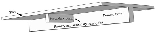
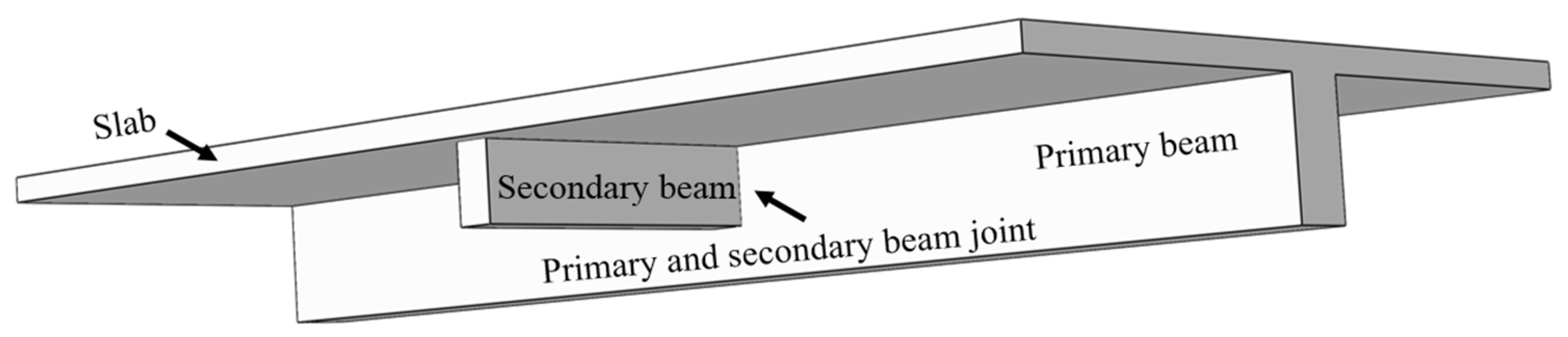
Reinforced concrete primary and secondary beam joints are located at the intersection of primary and secondary beams, functioning to transfer slab loads to secondary beams in the form of concentrated loads, which are subsequently transmitted to primary beams [22,23]. In this study, a primary beam with a span of 5.1 m and cross-sectional dimensions of 250 mm × 500 mm is selected as the research object. The secondary beam intersects the midspan of the primary beam, and the schematic diagram of the primary and secondary beam joint is illustrated in Figure 1. The conventional reinforcement configuration of the primary beam alone cannot satisfy the requirements of bearing capacity and mechanical performance. Therefore, additional transverse reinforcement is required to be arranged at the joint region to resist the applied concentrated load.
Figure 1.
Schematic diagram of the primary and secondary beam joint.
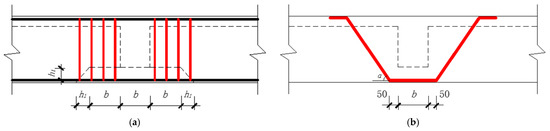
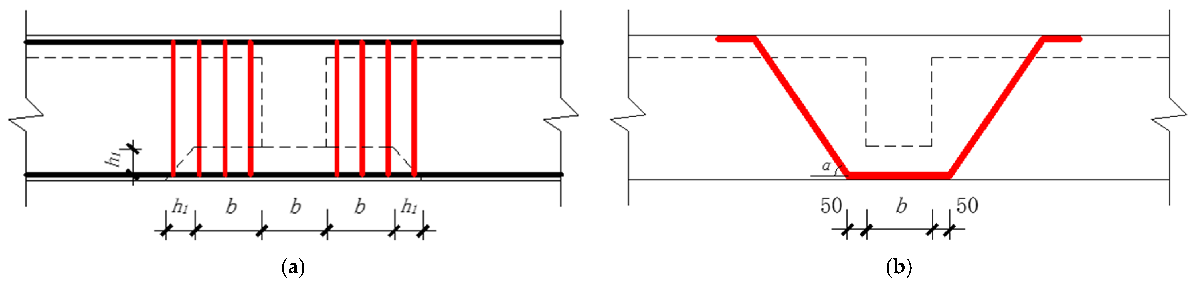
For the additional reinforcement of primary and secondary beam joints, the configuration and geometric relationship of additional transverse reinforcement are illustrated in Figure 2. Additional stirrups feature the advantages of simple design and convenient construction. Nevertheless, restricted by the limited configuration quantity and the relatively small concrete cover thickness, stirrups exhibit deficiencies in bearing capacity and durability performance. In contrast, additional hanging reinforcement can effectively compensate for the shortcomings of additional stirrups. For conditions involving a small height difference between primary and secondary beams, large secondary beam loads, or service in marine corrosive environments, the current design code [11] lacks clear provisions on joint reinforcement modes. Targeting this engineering research gap, this study investigates the mechanical performance of primary and secondary beam joints with different reinforcement modes, and further explores their mechanical behavior considering reinforcement corrosion.
Figure 2.
Configuration and geometric relationship of additional transverse reinforcements: (a) additional stirrups and (b) additional hanging reinforcement.
2.2. Special Force Situations
2.2.1. “Small Height Difference” Situation
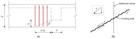
The design code [11] stipulates that additional stirrups shall be arranged within the specified range of 3b + 2h1 at primary and secondary beam joints to fully resist the concentrated loads transferred from secondary beams. Insufficient bearing capacity provided by additional stirrups may easily induce concrete cracking and structural failure within this region. Figure 3a presents the schematic diagram of the concrete cracking propagation angle. Based on the previous studies by Hou et al. [24] and Hu et al. [25], the relational expression for the concrete cracking propagation angle at the primary and secondary beam joints is established as Equation (1).
where β is the concrete cracking propagation angle (°). b is the width of the secondary beam (mm). h1 is the height difference between the primary and secondary beams (mm). Taking the height difference between primary and secondary beams as the single variable, this study establishes a relational formula between the concrete cracking propagation angle and the beam height difference, as presented in Equation (2).
where H is the height of the primary beam (mm). is the height–width ratio of the secondary beam. h is the height of the secondary beam (mm). In general engineering, this ratio generally ranges from 2 to 4, and is set to 3 in this study [11].
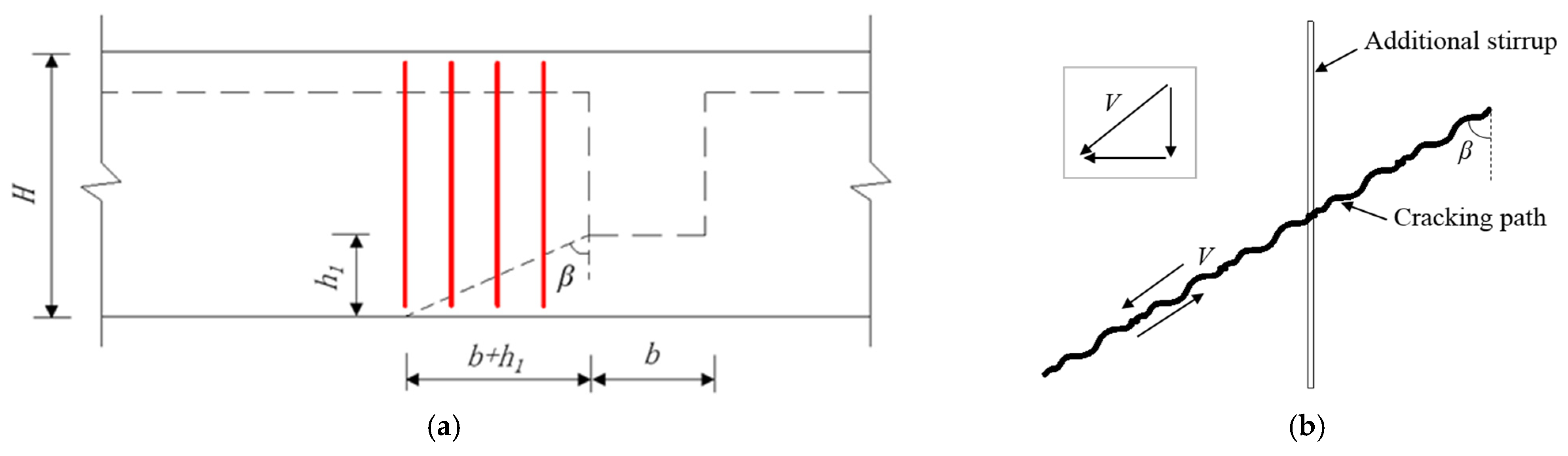
Figure 3.
Schematic diagram of (a) concrete cracking propagation angle and (b) force distribution of additional stirrups.
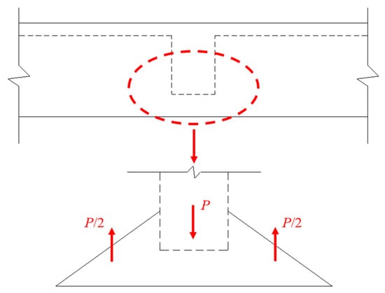
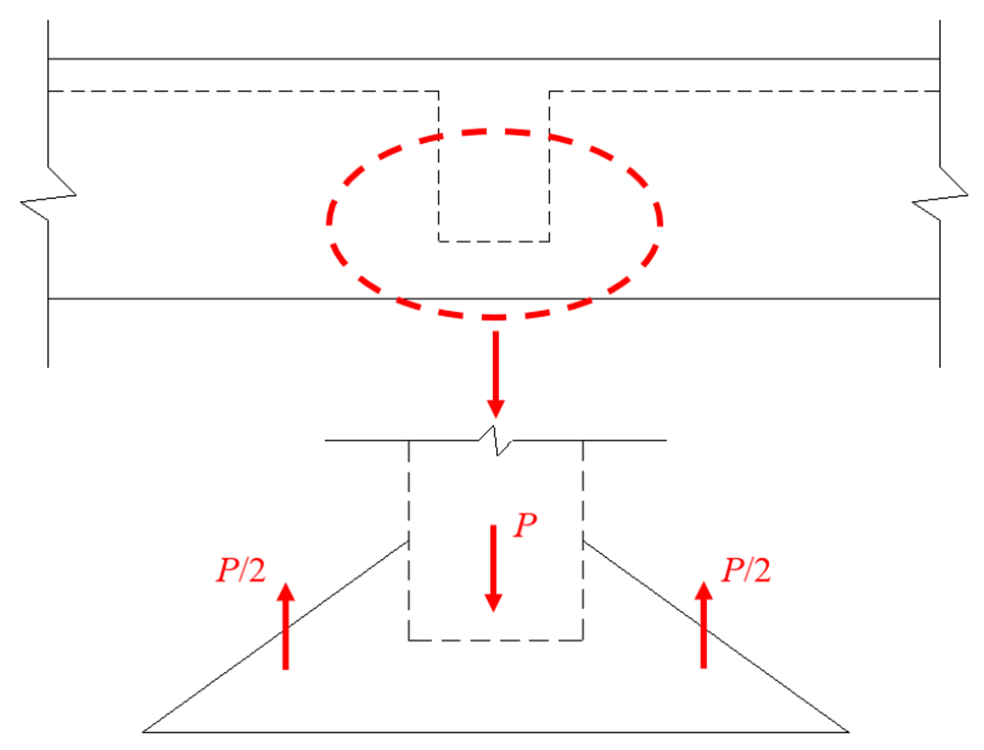
As observed in Figure 3b, the additional stirrups arranged along the cracking path are subjected to a shear force V. After force decomposition, these stirrups are actually under combined shear and tension. This finding is consistent with the research conclusions of Li et al. [26] and Deifalla et al. [27] on the shear transfer behavior of reinforced concrete interfaces. However, the configuration requirements for additional stirrups specified in the design code [11] are formulated based on tensile design criteria. Regarding the mechanical behavior of additional stirrups, Mozaffari et al. [28] established a correlation between the strut-and-tie model and reinforced concrete design by selecting an isolated element at the primary and secondary beam joint, which provides a reference for the internal reinforcement design of concrete members. The concentrated load at the primary and secondary beam joint and the force state of additional stirrups on both sides of the joint are illustrated in Figure 4. The concentrated load is entirely borne by the tensile capacity of the additional stirrups. Under concentrated loading, if the stirrups bear a large shear force yet a relatively small tensile force, they will be dominated by shear action and cannot provide adequate tensile resistance. In this situation, part of the tensile force will be carried by the concrete. Consequently, tensile stress develops within the concrete. Once the tensile stress exceeds the tensile strength of concrete, cracking and eventual failure will occur at the primary and secondary beam joint.
Figure 4.
Concentrated load at the primary and secondary beam joint and the force state of additional stirrups.
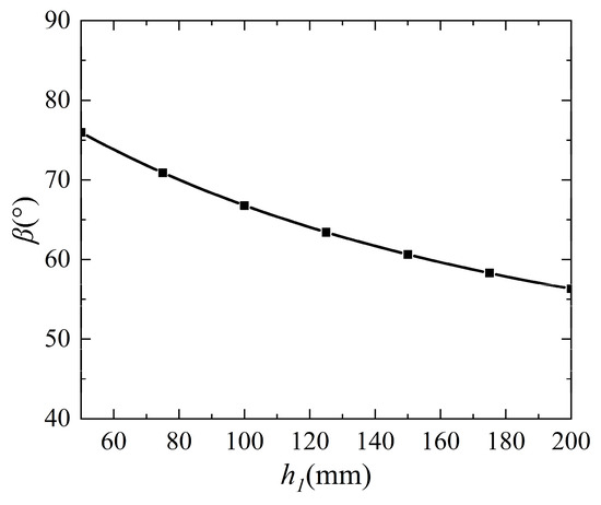
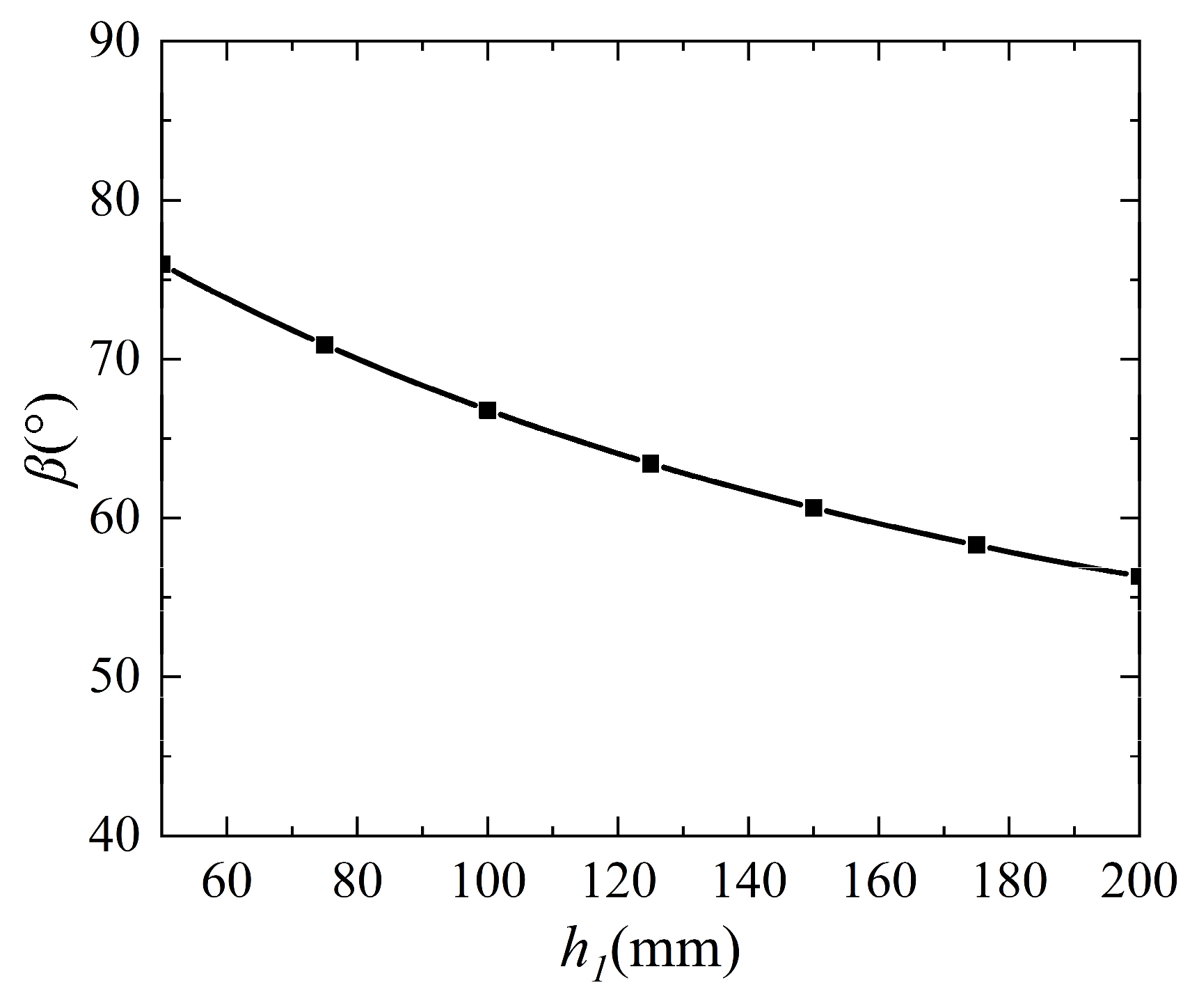
Based on Equation (2), the relationship between the concrete cracking propagation angle and the height difference between the primary and secondary beams is illustrated in Figure 5. As the beam height difference decreases, the concrete cracking propagation angle gradually increases. Meanwhile, the shear force carried by the additional stirrups also increases. The force state of the additional stirrups transitions from tension-dominated to shear-dominated, rendering the stirrups unable to provide sufficient tensile capacity. Based on the above analysis, the special situation induced by a small height difference between the primary and secondary beams is defined as the “small height difference” situation.
Figure 5.
Relationship between the concrete cracking propagation angle and the height difference between the primary and secondary beams.
2.2.2. “Large Load” Situation
According to the requirements of the design code [11], the maximum configuration quantity of additional stirrups n can be calculated by Equation (3).
where f is the distance from the first additional stirrup to the secondary beam (mm), which is specified as 50. s is the spacing of the additional stirrups (mm), and it is generally set at 50. Taking the height difference between primary and secondary beams as the single variable, a relational formula between the quantity of additional stirrups and the height difference can be established, as presented in Equation (4).
Furthermore, as specified in the design code [11], the required cross-sectional area of additional transverse reinforcement is determined according to the magnitude of the concentrated load at the primary and secondary beam joints, as expressed in Equation (5).
where Asv is the total cross-sectional area of loaded additional transverse reinforcement (mm2). When the additional hanging reinforcement is adopted, Asv shall be the sum of the cross-sectional areas of the bent segments on both sides. P is the design value of the load acting at the beam bottom or within the beam section height (N). fyv is the design value of the tensile strength of the additional stirrups (N/mm2). α is the included angle between additional transverse reinforcement and the beam axis (°). The angle is 90° for the additional stirrups, while 45° is adopted for the additional hanging reinforcement in this study. The required cross-sectional area can be expressed by the configuration quantity of additional stirrups, namely Asv = 2nAsv1. Substituting this into the formula yields the relationship between the quantity of additional stirrups and the applied load, as presented in Equation (6).
where Asv1 is the cross-sectional area of the additional stirrups (mm2).
The height difference between the primary and secondary beams and the magnitude of concentrated loads are the dominant factors affecting the configuration of additional stirrups at joints. Equation (4) determines the maximum quantity of additional stirrups under different beam height differences, while Equation (6) gives the design value of the concentrated load corresponding to different quantities of reinforcement. As the quantity of additional stirrups increases, a discrepancy gradually emerges between the actual concentrated load and the design value. The additional stirrups are unable to fully carry the corresponding design concentrated load. This special situation is defined as the “large load” situation.
The situations of “small height difference” and “large load” can indeed be largely explained by the strut-and-tie mechanism and associated changes in load paths. However, the main contribution of this study is not the discovery of new situations; rather, it focuses on providing practical engineering-oriented work for special situations in primary and secondary beam joints, converting these special situations into empirical conclusions that can be directly used in engineering design.
2.3. Reinforcement Corrosion Theory
Based on the research results of Zhu et al. [29], the circumferential radius reduction r of corroded reinforcement can be calculated by Equation (7).
where AFe is the atomic weight of iron (g/mol). t1 is the corrosion initiation time of reinforcement (s). itotal is the total corrosion current density (A/m2). ZFe is the valence state of iron in the anodic reaction. F1 is the Faraday constant. ρs is the density of reinforcement (kg/m3). Subsequently, the corrosion rate η expression of reinforcement is derived and presented in Equation (8).
where R is the radius of the reinforcement (m). Regarding the deterioration of mechanical properties of corroded reinforcement, this study adopts the experimentally regressed elastic modulus and yield strength of non-uniformly corroded reinforcement proposed by Wu et al. [30]. The corresponding expressions are given in Equations (9) and (10).
where Es and are the elastic modulus of the uncorroded and corroded reinforcement, respectively (MPa). η is the reinforcement corrosion rate (%). Fy and are the yield strengths of uncorroded and corroded reinforcement, respectively (MPa).
3. Numerical Modeling
For the reinforcement modes and corrosion issues of primary and secondary beam joints, various numerical methods can be employed. The finite element method excels in handling complex geometries and material nonlinearities; the finite difference method [31] is simple to program and computationally efficient, making it suitable for transient problems such as chloride diffusion; the Bessel multi-step method [32] offers high accuracy and good stability when solving strongly nonlinear equations. Given the complex boundary conditions and nonlinearities in this study, the finite element method was ultimately selected as the core tool, using ABAQUS (version 2024) [33] to establish a three-dimensional model to evaluate the bearing capacity of the joint and COMSOL (version 5.4) [34] to solve the two-dimensional chloride diffusion field.
3.1. Finite Element Model of Reinforcement Mode
3.1.1. Geometric Model
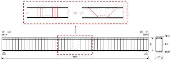
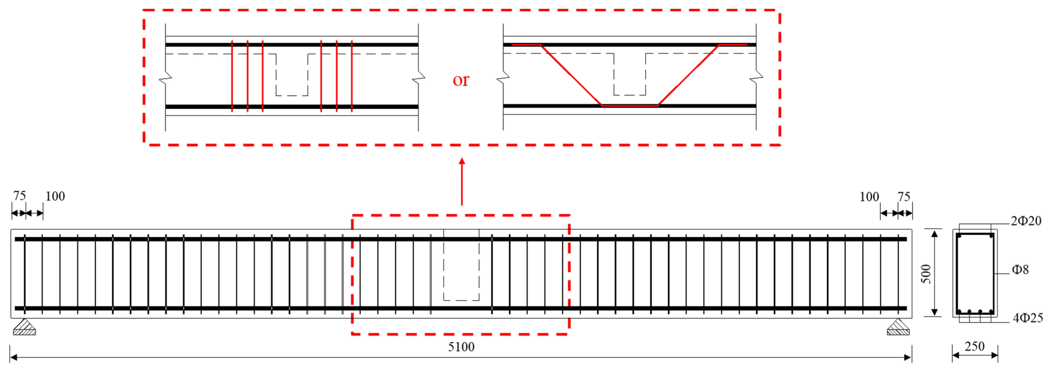
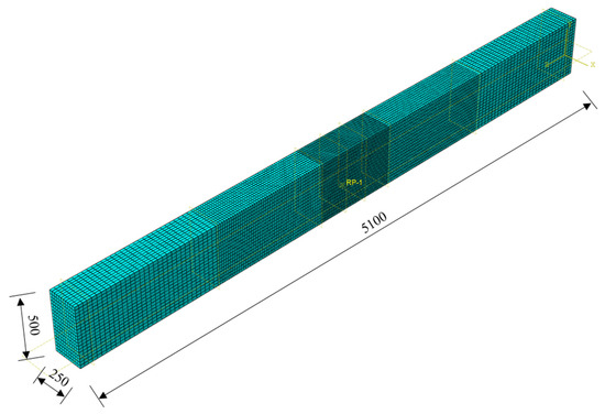
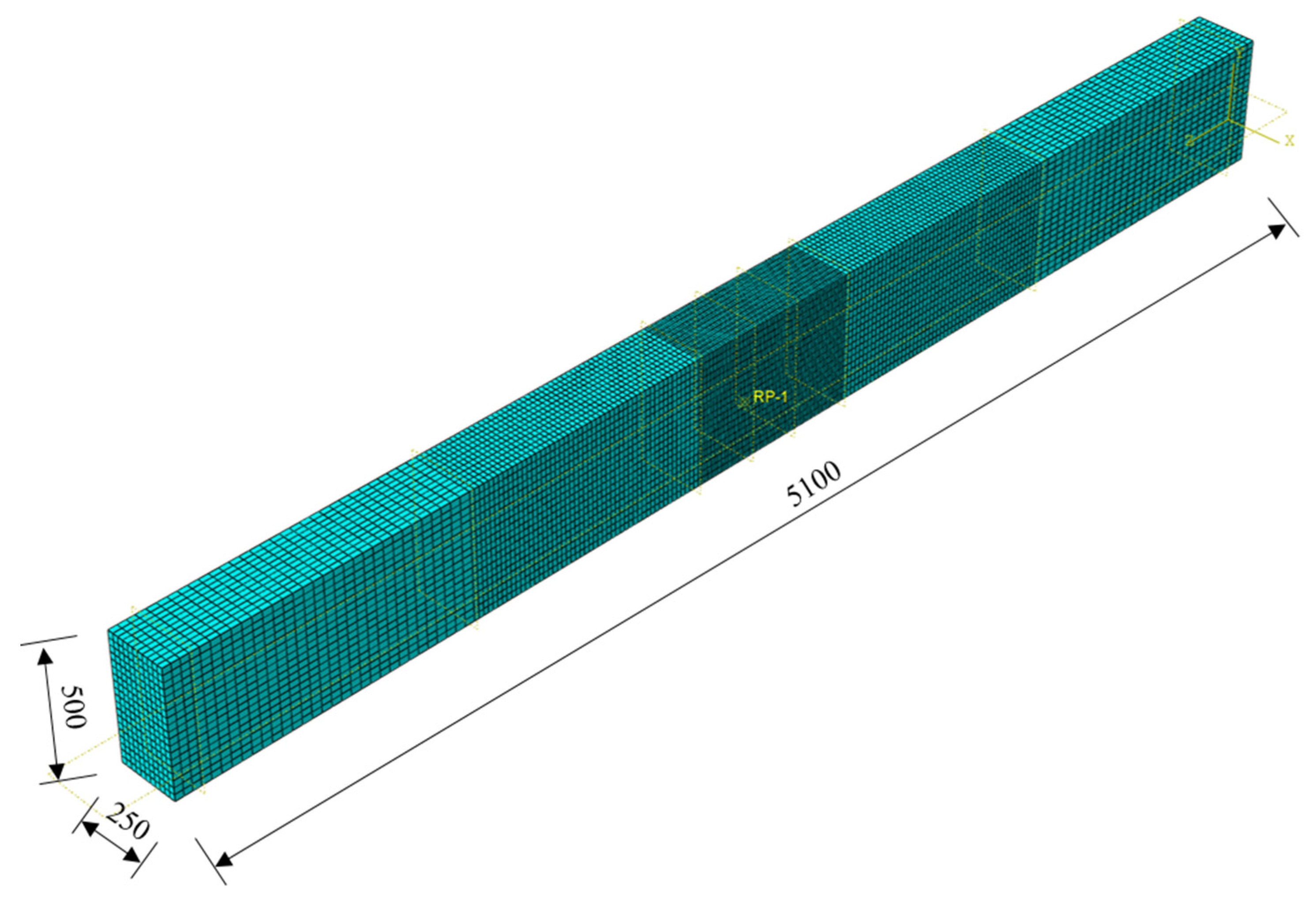
To address the above two special situations, finite element numerical models are established using ABAQUS CAE for parametric analysis. Based on practical engineering conditions, the primary beam adopts dimensions of 5100 mm × 250 mm × 500 mm (length × width × depth) with simply supported constraints at both ends. The cross-sectional dimensions of the secondary beam are adjusted correspondingly according to the height difference between the primary and secondary beams. The geometric model is illustrated in Figure 6. In the numerical model, the concrete strength grade is C30 with a concrete cover thickness of 20 mm. For the primary beam, four rebars with a diameter of 25 mm are arranged as tensile longitudinal reinforcement, and two rebars of 20 mm diameter are used as compressive longitudinal reinforcement. The stirrups adopt a diameter of 8 mm and a spacing of 100 mm.
Figure 6.
Schematic diagram of the geometric model.
3.1.2. Constitutive Model and Interactions
In the finite element model, the concrete damaged plasticity model provided in ABAQUS CAE is adopted as the constitutive model of concrete [35,36]. Concrete is simulated by three-dimensional solid elements, specifically C3D8R (eight-node hexahedral reduction integration element). For reinforcement, an ideal elastic–plastic constitutive model is employed and modeled with T3D2 linear truss elements [37]. The established finite element model is displayed in Figure 7, and the physical and mechanical parameters of concrete and reinforcement are listed in Table 1. Regarding the interaction between the reinforcement and concrete, the embedded simplification method is adopted to embed the reinforcement elements into the concrete matrix, i.e., relative slip is not considered, thereby achieving deformation compatibility between the reinforcement and concrete elements. This study primarily investigates reinforced concrete primary and secondary beam joints without considering corrosion damage, and this bond simplification is generally acceptable [38]. To prevent stress concentration at the loading position, point-to-surface coupling constraints are applied, where the reference point for displacement loading is coupled to the bottom surface of the secondary beam.
Figure 7.
Schematic diagram of the finite element model.
Table 1.
Physical and mechanical parameters of material.
3.1.3. Simulation Conditions
In the numerical simulation, displacement loading is applied by setting a reference point at the midspan of the beam. The purpose of this setup is to simulate the deformation of the primary beam caused by the load on the secondary beam. Under the special situations of a small height difference and a large load, the primary beam undergoes significant flexural and shear deformations. The internal forces in the joint region are governed by the relative displacement between the end of the secondary beam and the web of the primary beam, and this relative displacement is directly related to the midspan deflection of the primary beam. Therefore, this study suggests that applying displacement control at the midspan of the primary beam can effectively drive the joint through a complete loading process.
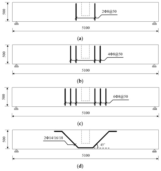
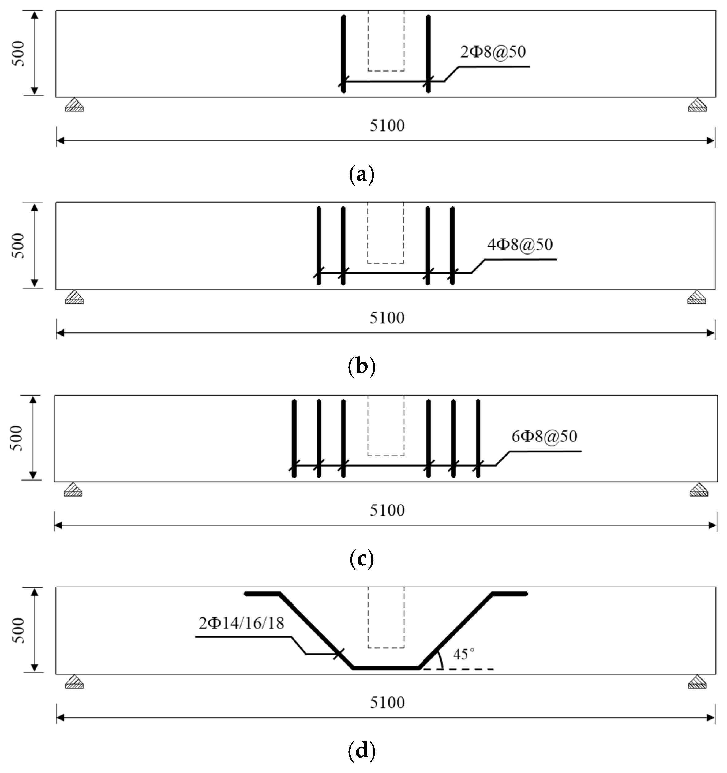
To investigate the mechanical behavior of primary and secondary beam joints under different reinforcement modes, four simulation cases are established based on practical engineering conditions. The schematic diagram of different reinforcement modes at the joints is presented in Figure 8. The additional stirrups are provided in quantities of 2, 4, and 6, all with a diameter of 8 mm. The additional hanging reinforcement is provided in a quantity of 2, with diameters of 14 mm, 16 mm, and 18 mm.
Figure 8.
Schematic diagram of different reinforcement modes at the primary and secondary beam joints: (a) 2 additional stirrups, (b) 4 additional stirrups, (c) 6 additional stirrups and (d) 2 additional hanging reinforcement.
3.2. Finite Element Model of Reinforcement Corrosion
3.2.1. Geometric Model
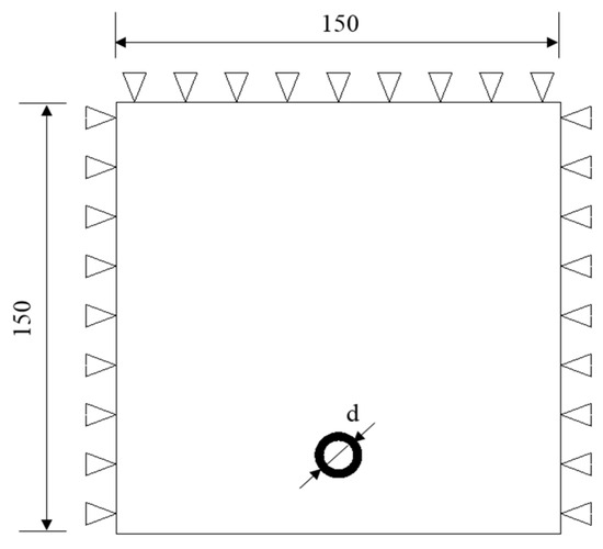
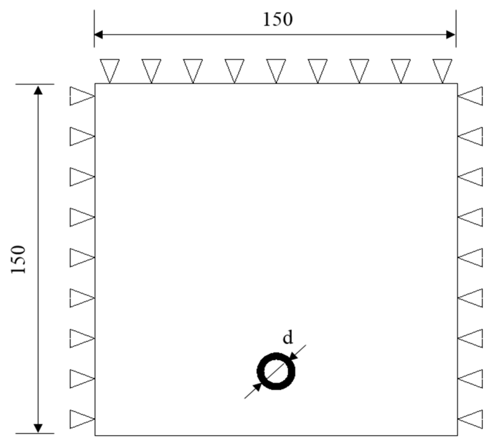
With regard to reinforcement corrosion, the code [16] specifies that reinforcement embedded in concrete experiences the most severe corrosion under alternating dry–wet conditions (i.e., the splash zone) with sufficient oxygen and moisture supply. In marine environments, chloride ingress is one of the primary factors inducing reinforcement corrosion [39,40,41]. Referring to the research findings of Ožbolt et al. [42] and Yao et al. [43], a two-dimensional reinforcement corrosion model is established using the finite element software COMSOL, with the geometric model illustrated in Figure 9.
Figure 9.
Schematic diagram of the geometric model.
3.2.2. Model Parameter
This model couples multiple processes, including heat transfer, moisture transport, and chloride diffusion, to simulate the corrosion process of reinforcement and obtain post-corrosion data. According to the definition of the marine chloride environment in the standard [16], the relevant parameters for chloride erosion in the model are presented in Table 2. COMSOL performs a time-dependent simulation of the entire reinforcement corrosion process by solving the initial parameters.
Table 2.
Chloride erosion-related parameters.
3.3. Model Verification
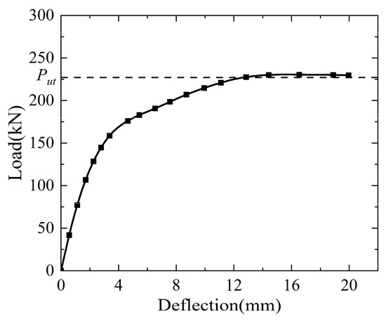
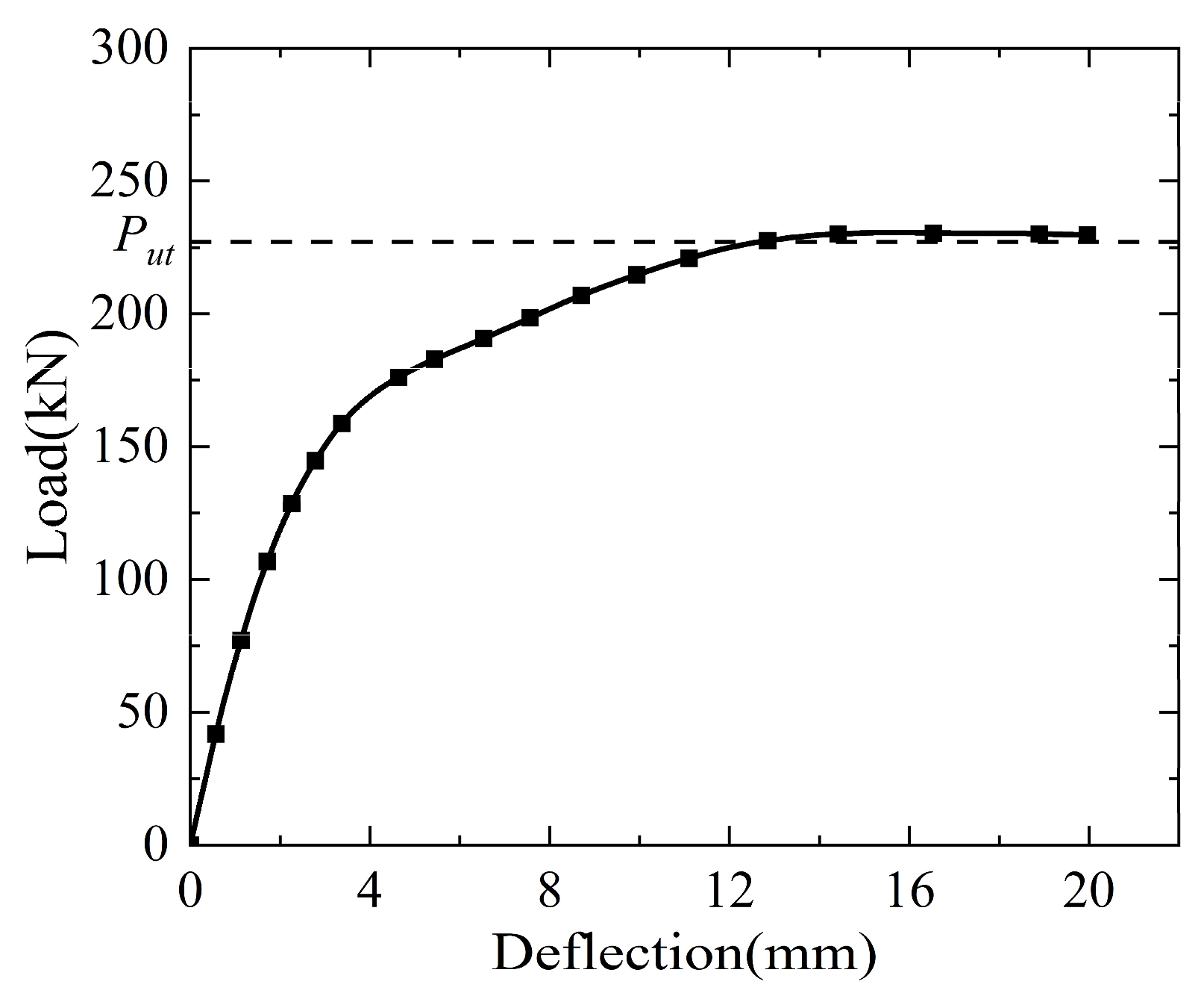
The ultimate bearing capacity is a key indicator reflecting the mechanical behavior of beams, which can be well characterized by the horizontal segment of the load–deflection curve. To validate the rationality of the established finite element model, a beam without additional transverse reinforcement is selected for verification, with all other parameters kept unchanged. The theoretical formula for calculating the normal-section bearing capacity of beams, as specified in Section 6.2 of the code [11], is presented in Equation (11).
where M is the design value of the bending moment (kN·m). α1 is a coefficient. fc is the design value of the axial compressive strength of concrete (MPa). b is the width of the beam section (mm). x is the height of the concrete compression zone in the equivalent rectangular stress graph (mm). h0 is the effective height of the beam section (mm). is the design value of the compressive strength of reinforcement (MPa). is the cross-sectional area of longitudinal reinforcement in the compression zone (mm2). is the distance from the resultant force point of the longitudinal reinforcement in the compression zone to the compression edge of the section (mm).
Considering Equation (7) and (the relationship between the bending moment and ultimate bearing capacity), the design value of the ultimate bearing capacity Put for the simply supported beam under midspan concentrated load is obtained as 227.10 kN. The load–deflection curve of the beam obtained from the numerical simulation is presented in Figure 10, showing a simulated ultimate bearing capacity of 230.63 kN. The relative error between the simulated and the design values is only 1.54%, confirming the rationality of the finite element model and the reliability of the simulation results.
Figure 10.
Load–deflection curve of beam.
Meanwhile, to verify the reliability and accuracy of the beam model with additional transverse reinforcement, this study established a primary and secondary beam joint model with the same dimensions and boundary conditions as those in Zhang’s experiment [48], and compared the results with field experiment data. In that experiment, the primary beam dimensions were 2000 mm × 400 mm × 650 mm (length × width × depth), and the cross-sectional dimensions of the secondary beam varied with the height difference between the primary and secondary beams. Further details can be found in [48].
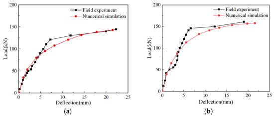
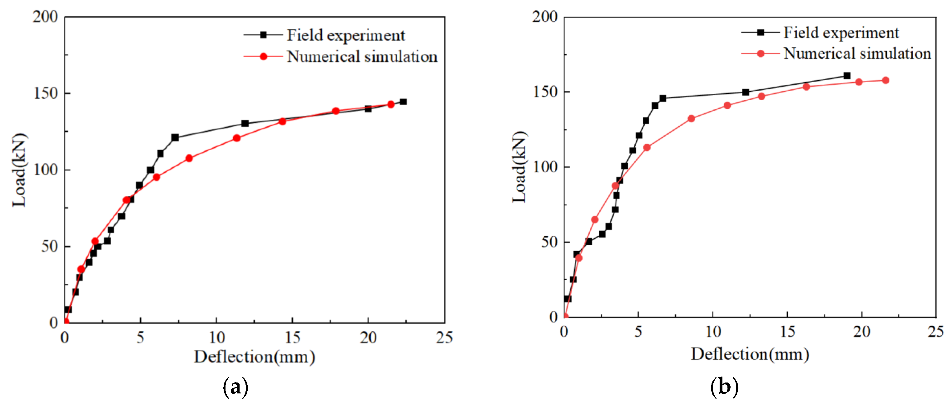
Figure 11 shows a comparison of the numerical and experimental load–deflection curves for height differences of h1 = 50 mm and 150 mm. It can be observed that the two exhibit good consistency in terms of the trend. However, the numerical simulation results are slightly lower than the experimental results. This is because the numerical simulation simplifies the actual experimental conditions, resulting in a slightly higher beam stiffness than in reality. Although there are some differences between the simulated and experimental results, the errors are small, indicating that the model presented in this study is reasonably valid.
Figure 11.
Comparison of field experiment and numerical simulation: (a) h1 = 50 mm and (b) h1 = 150 mm.
4. Result Analysis and Discussion
4.1. Reinforcement Mode
It can be observed from Figure 5 that the concrete cracking propagation angle changes significantly when the height difference between the primary and secondary beams is small. Therefore, numerical simulations are carried out for the three cases illustrated in Figure 8a–c under the condition of uncorroded reinforcement. For each case, the height differences between the primary and secondary beams are set to 50 mm, 100 mm, 150 mm and 200 mm, corresponding to maximum additional stirrup quantities of 8, 8, 10 and 12, respectively. In all cases, the quantity of additional stirrups remains within the maximum limit allowed by the reinforcement configuration range.
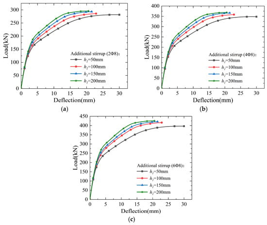
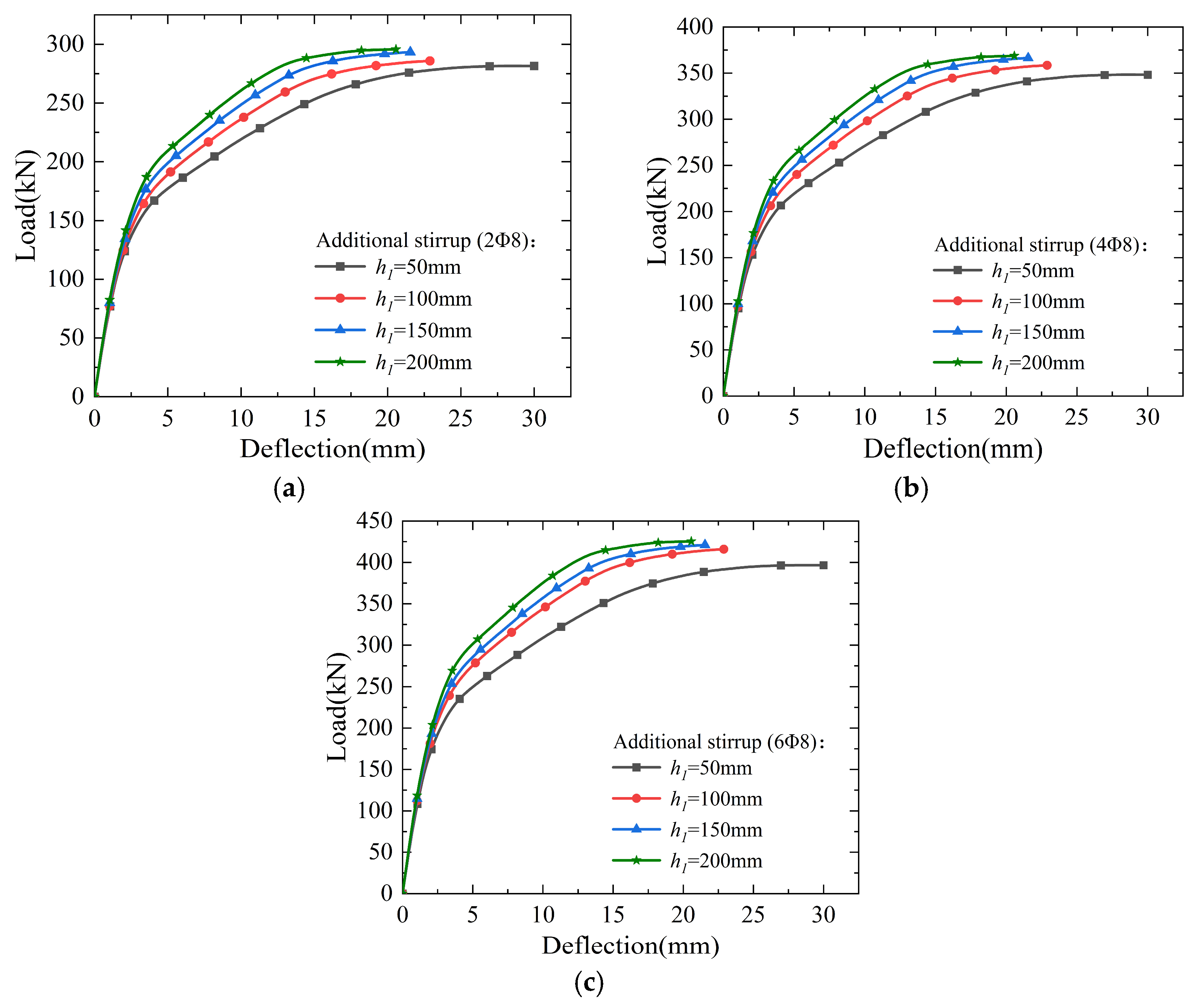
The load–deflection curves of the beam joints under cases (a), (b) and (c) are presented in Figure 12. It is evident that the height difference between the primary and secondary beams is a key factor affecting the ultimate bearing capacity of the beams. For cases with different height differences, the ultimate bearing capacity varies accordingly, decreasing as the height difference reduces. The numerical results indicate that when the ratio of the height difference between the primary and secondary beams to the height of the primary beam, h1/H ≤ 0.2, the primary and secondary beam joints exhibit an obvious “small height difference” situation. In particular, when the height difference is 50 mm, i.e., h1/H = 0.1, the reduction in ultimate bearing capacity becomes more significant. Accordingly, the error between the theoretical and simulated ultimate bearing capacities at a height difference of 50 mm is calculated and summarized in Table 3. As the quantity of additional stirrups at the primary and secondary beam joint increases, the contribution of the additional stirrups to the ultimate bearing capacity of the beam gradually decreases. When the quantity of additional stirrups is two or four, the error between the theoretical and simulated values is approximately 6%. However, when the quantity increases to six, the error reaches 10.73%.
Figure 12.
Load–deflection curve diagram of beam under different cases (with additional stirrups): (a) 2Φ8, (b) 4Φ8 and (c) 6Φ8.
Table 3.
Error between theoretical and simulated ultimate bearing capacity (h1 = 50 mm).
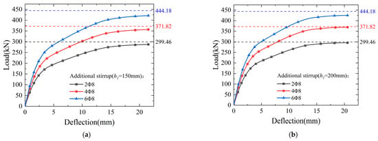
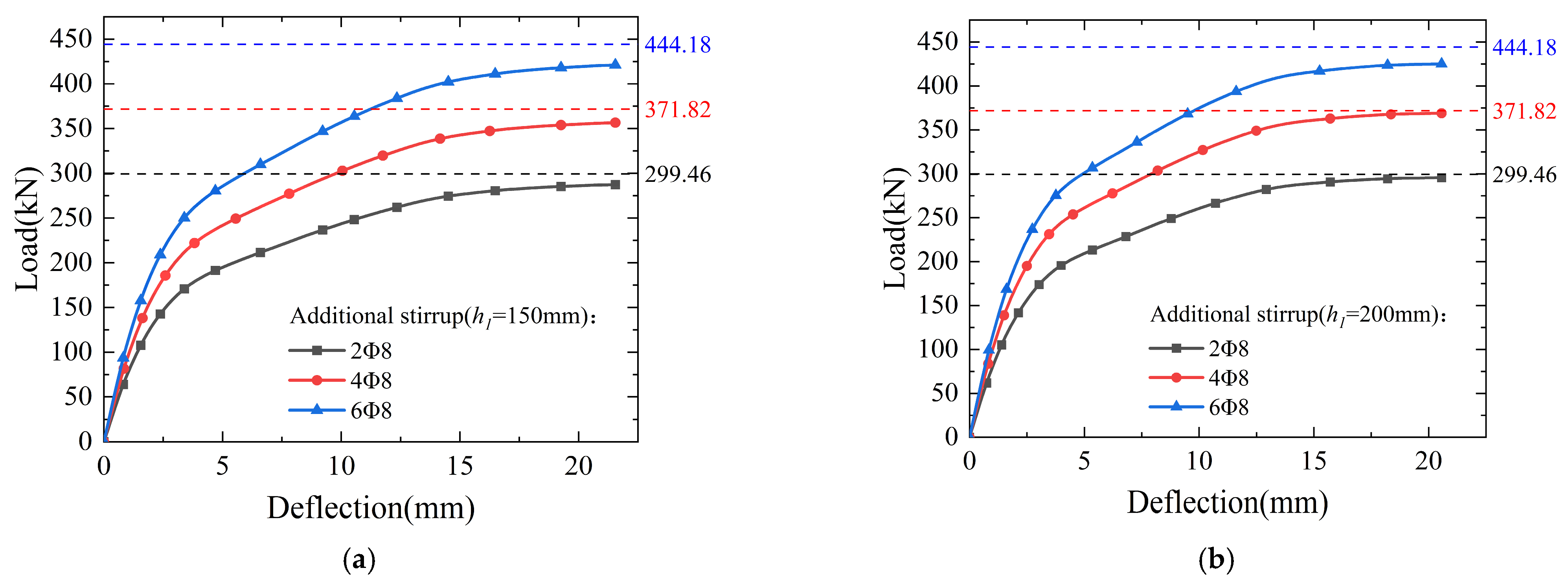
Beyond the influence range of the “small height difference” situation, the load–deflection curves of the joints under cases (a), (b) and (c) at beam height differences of 150 mm and 200 mm are plotted in Figure 13. The values indicated by the dashed lines correspond to the theoretical ultimate bearing capacities for the three cases. It can be observed that in beams with additional stirrups, when there are six additional stirrups, these stirrups are not fully utilized, and the ultimate bearing capacity of the beams cannot achieve the preset theoretical value. For a fixed height difference between the primary and secondary beam, the simulated ultimate bearing capacity gradually deviates from the theoretical value as the quantity of additional stirrups increases. The numerical simulation results in Figure 13 indicate that when the height difference between the primary and secondary beams is relatively large, and the ratio of the simulated ultimate bearing capacity to the theoretical value, P/Pu ≤ 0.95, the primary and secondary beam joint exhibits a “large load” situation. The errors between the theoretical and simulated ultimate bearing capacities for beams with a height difference of 200 mm are calculated and presented in Table 4. The errors for beams with additional stirrups are relatively unstable and large. Specifically, when the quantity of additional stirrups is six, the error reaches 4.31%, while the errors for two and four additional stirrups are not significant.
Figure 13.
Load–deflection curve diagram of beam under different cases (with additional stirrups): (a) h1 = 150 mm and (b) h1 = 200 mm.
Table 4.
Error between theoretical and simulated ultimate bearing capacity (h1 = 200 mm).
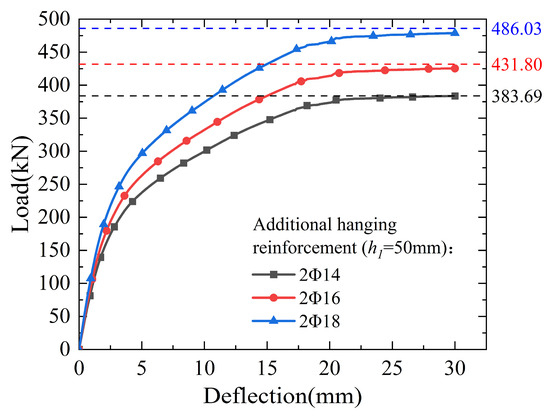
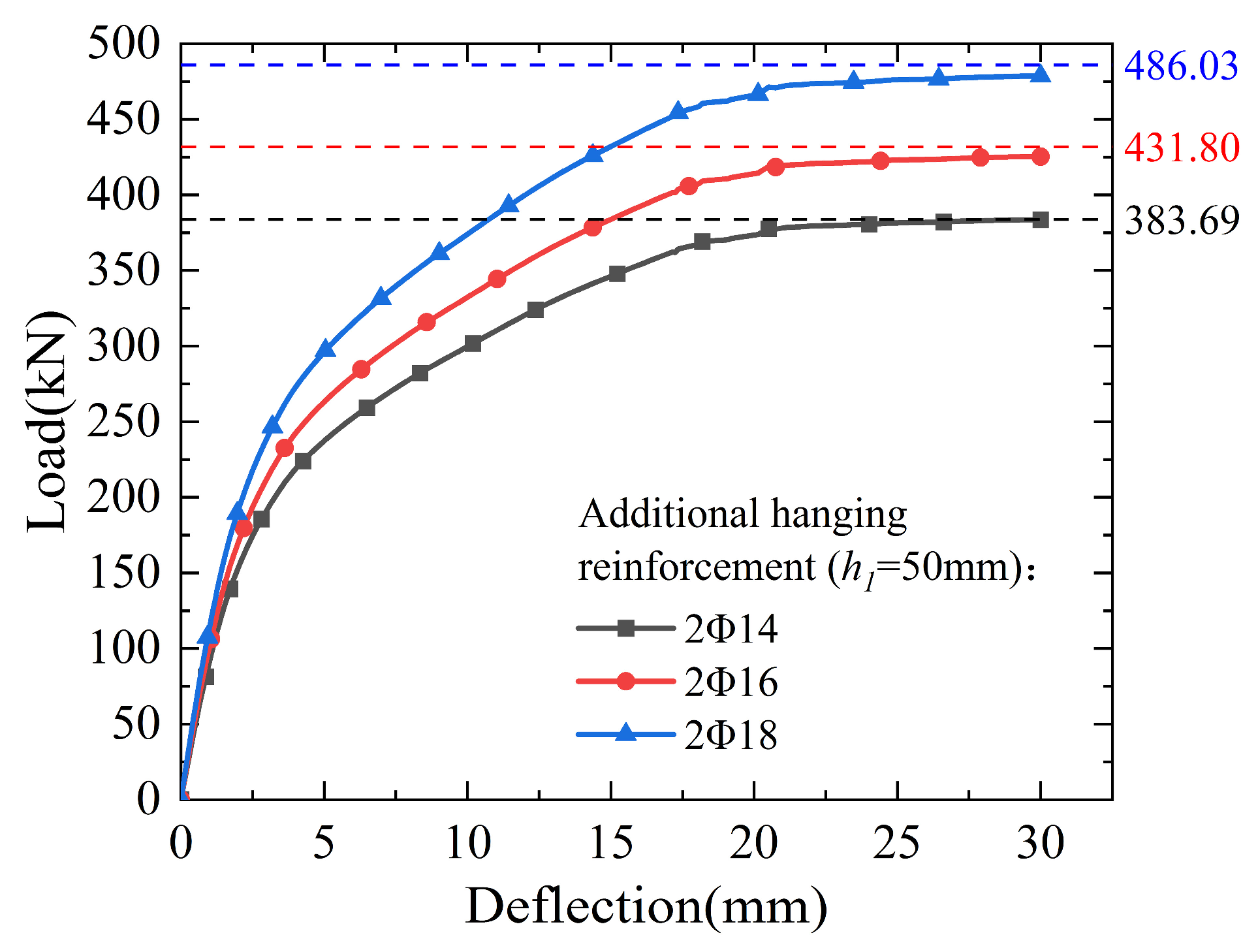
To compare the mechanical behavior of primary and secondary beam joints with additional stirrups, a numerical simulation is carried out for the case illustrated in Figure 8d at a beam height difference of 50 mm. The corresponding load–deflection curve is presented in Figure 14. It can be observed that the simulated ultimate bearing capacity is in good agreement with the theoretical value. Compared with the beam with additional stirrups having a similar total reinforcement cross-sectional area, the beam with six 8 mm diameter stirrups had a theoretical ultimate bearing capacity of 444.18 kN, while the simulated value was 396.5 kN, exhibiting the “small height difference” situation. In contrast, the beam with additional 14 mm diameter hanging reinforcement had theoretical and simulated ultimate bearing capacities that were very close, approximately 383.69 kN, and did not exhibit either of the two special situations mentioned above. This demonstrates that the additional hanging reinforcement can effectively resist the concentrated loads at the primary and secondary beam joints. Comparative analysis indicates that the difference between the theoretical and simulated ultimate bearing capacities of additional hanging reinforcement is not as large as that of additional stirrups, and the hanging reinforcement can better carry the concentrated load at the primary and secondary beam joint. Therefore, under the two special situations, additional hanging reinforcement should be selected as the reinforcement mode for primary and secondary beam joints.
Figure 14.
Load–deflection curve diagram of beam (with additional hanging reinforcement).
4.2. Reinforcement Corrosion
In marine environments, chloride ingress-induced reinforcement corrosion is an inevitable phenomenon. Mitigating the damage caused by reinforcement corrosion is essential for the durability design of primary and secondary beam joints. Considering the harsh conditions of coastal environments and the actual service life of structures, numerical simulations are performed for the beam joints under cases (c) and (d) shown in Figure 8. For case (d), the additional hanging reinforcement has a diameter of 16 mm, and the concrete cover thickness is 25 mm.
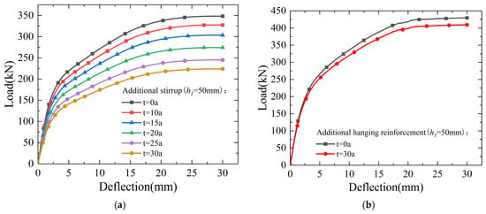
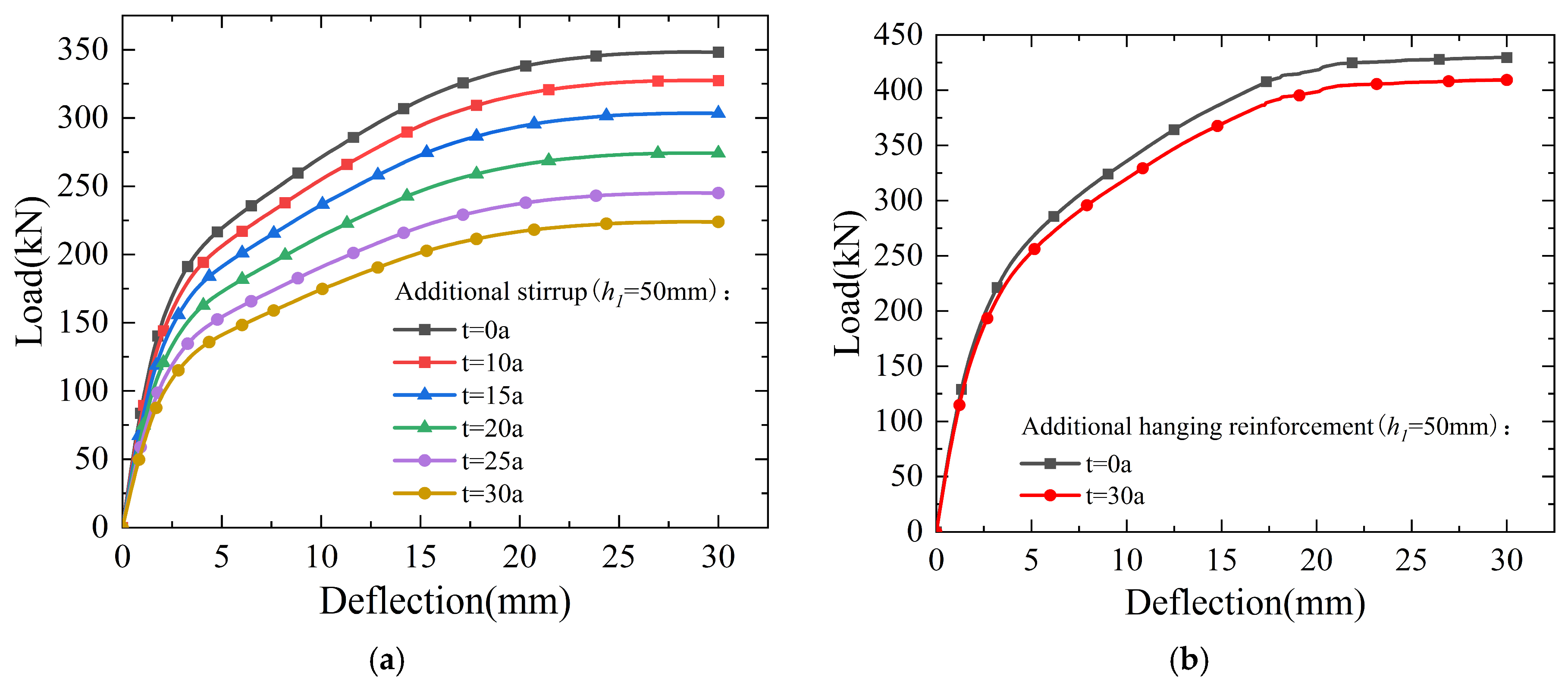
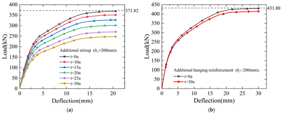
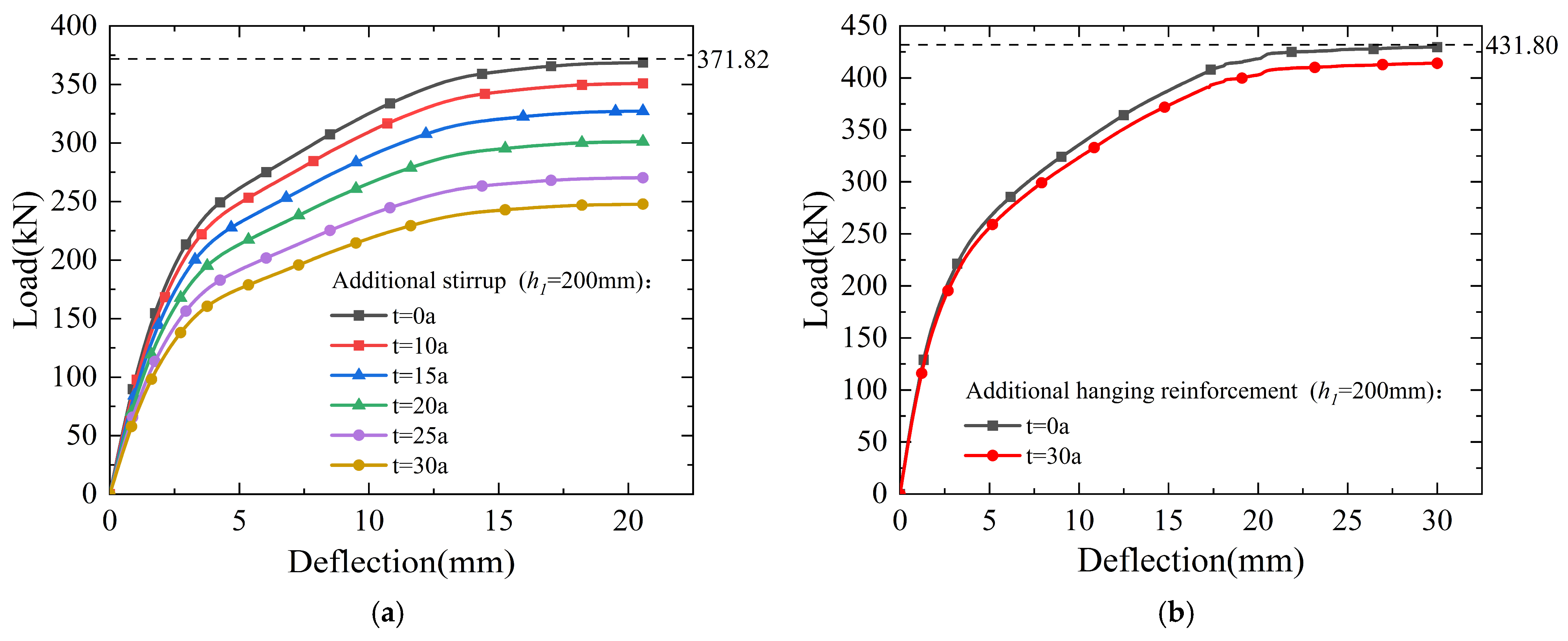
Figure 15 and Figure 16 present the load–deflection curves of beams with reinforcement under different corrosion durations. Since the load-carrying capacity of beams with additional hanging reinforcement decreases only slightly during the entire corrosion process, to clearly illustrate the overall trend of the corrosion effect on the beams, only the two extreme corrosion cases—the shortest corrosion duration (0 years) and the longest corrosion duration (30 years)—are selected for comparison. It is evident that reinforcement corrosion leads to varying degrees of reduction in the ultimate bearing capacity of beams. Notably, when additional stirrups are arranged at primary and secondary beam joints, the degradation of ultimate bearing capacity becomes more pronounced. The reduction in the ultimate bearing capacity of the beam with additional stirrups at a corrosion duration of 10 years is approximately the same as that of the beam with additional hanging reinforcement at a corrosion duration of 30 years. The main reason is that the corrosion severity of additional stirrups is higher than that of additional hanging reinforcement. First, the concrete cover thickness of additional stirrups is smaller, so chloride-induced corrosion initiates earlier in stirrups than in hanging reinforcement. Second, the diameter of additional stirrups is smaller than that of additional hanging reinforcement. After the onset of corrosion, the corrosion rate of stirrups is greater, leading to severe deterioration of their mechanical properties. This ultimately causes a more significant drop in the ultimate bearing capacity of the beam. Accordingly, under the two special situations in the presence of reinforcement corrosion, additional hanging reinforcement is recommended as the preferred reinforcement mode for primary and secondary beam joints.
Figure 15.
Load–deflection curve diagram of beam under different corrosion durations (h1 = 50 mm): (a) additional stirrups and (b) additional hanging reinforcement.
Figure 16.
Load–deflection curve diagram of beam under different corrosion durations (h1 = 200 mm): (a) additional stirrups and (b) additional hanging reinforcement.
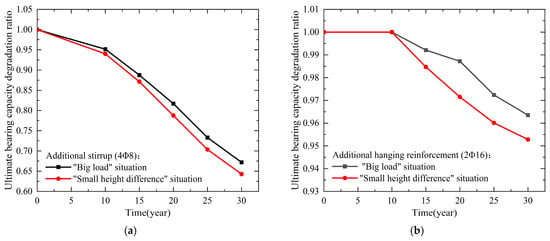
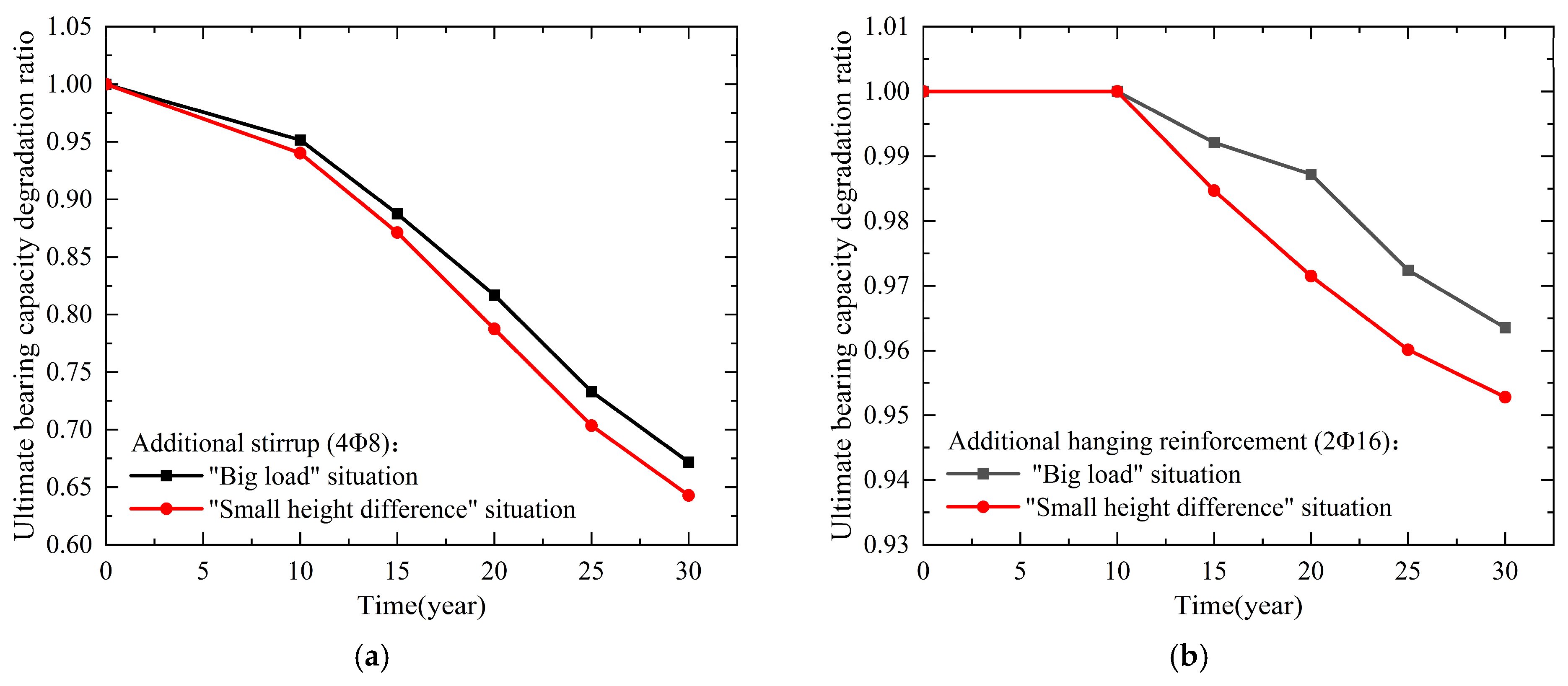
In order to more clearly illustrate the influence of reinforcement corrosion on the ultimate bearing capacity of beams, the ultimate bearing capacity degradation ratio is defined as the ratio of the ultimate bearing capacity of a corroded beam to that of an uncorroded beam. The variation in this degradation ratio is shown in Figure 17. It can be observed that when additional stirrups are arranged at the primary and secondary beam joints, the ultimate bearing capacity degradation ratio decreases more significantly. After 30 years of service, the degradation ratio of beams with additional stirrups drops to approximately 0.65. In contrast, when additional hanging reinforcement is adopted at the primary and secondary beam joints, the degradation ratio remains above 0.95.
Figure 17.
Curve of ultimate bearing capacity degradation ratio of the beam: (a) additional stirrups and (b) additional hanging reinforcement.
5. Conclusions
To guide the selection of additional transverse reinforcement for primary and secondary beam joints in practical engineering, this study investigates the mechanical performance of joints with different reinforcement modes, as well as the influence of reinforcement corrosion, through theoretical analysis and numerical simulation. The main conclusions are summarized as follows.
(1) Based on the mechanical analysis of primary and secondary beam joints and the established relationship between the applied load and beam height difference, two special situations of the joints are identified and verified. When the ratio of the height difference between the primary and secondary beams to the height of the primary beam, h1/H ≤ 0.2, the joint exhibits a “small height difference” situation. When the height difference between the primary and secondary beams is relatively large and the ratio of the simulated ultimate bearing capacity to the theoretical value, P/Pu ≤ 0.95, the joint exhibits a “large load” situation.
(2) Under these two special situations, additional stirrups may not fully function and fail to provide sufficient bearing capacity, which may induce potential structural safety risks. Therefore, under the “small height difference” and “large load” situations, additional hanging reinforcement should be adopted as the preferred reinforcement mode for primary and secondary beam joints.
(3) In marine service environments, when configuring additional stirrups at the primary and secondary beam joints, corrosion of the additional stirrups leads to a more significant decrease in the ultimate bearing capacity degradation ratio of the beam. After 30 years of service, the ultimate bearing capacity degradation ratio of the beam with additional stirrups drops to approximately 0.65, whereas that of the beam with additional hanging reinforcement remains above 0.95. Therefore, under the “small height difference” and “large load” situations involving reinforcement corrosion, additional hanging reinforcement is more suitable as the reinforcement mode of primary and secondary beam joints.
Despite these advances, the present numerical models inevitably simplify the authenticity of load transfer at primary and secondary beam joints, the construction process of reinforcement, and the environmental situations associated with reinforcement corrosion. Meanwhile, this study only examines several common reinforcement layouts in engineering practice, so the conclusions regarding the reinforcement modes have limitations. Future research should incorporate complex coupled effects, including structural loading, temperature stress, and corrosive media, and further consider damage mechanisms such as reinforcement corrosion-induced cracking, to develop more refined numerical models that better reflect real engineering situations. Meanwhile, further collection of field cases and experimental data is required to validate the realism of the simulation assumptions, enhance the reliability and generalizability of the findings, and broaden their engineering applicability.
Author Contributions
Conceptualization, X.C.; methodology, X.C.; software, X.C., X.L., Y.Z. and Y.P.; validation, X.C., X.L., Y.Z. and Y.P.; investigation, X.C., X.L., Y.Z. and Y.P.; data curation, X.C., X.L., Y.Z. and Y.P.; writing—original draft preparation, X.C.; writing—review and editing, X.C., X.L., Y.Z. and Y.P.; visualization, X.C.; supervision, X.C., X.L., Y.Z. and Y.P. All authors have read and agreed to the published version of the manuscript.
Funding
This research received no external funding.
Data Availability Statement
The original contributions presented in this study are included in the article. Further inquiries can be directed to the corresponding author.
Conflicts of Interest
Author Yankai Zhang was employed by the company China Petroleum Pipeline Engineering Corporation. The remaining authors declare that the research was conducted in the absence of any commercial or financial relationships that could be construed as a potential conflict of interest.
References
- Boscardin, J.T.; Yepes, V.; Kripka, M. Optimization of reinforced concrete building frames with automated grouping of columns. Autom. Constr. 2019, 104, 331–340. [Google Scholar] [CrossRef] [Scilit]
- Onat, Ö.; Evci, P.U. A parametric study in reinforced concrete frames with different infill wall materials. Bull. Earthq. Eng. 2024, 22, 4447–4476. [Google Scholar] [CrossRef] [Scilit]
- Nguyen, T.K.; Nguyen, N.T. Finite element investigation of the shear performance of corroded RC deep beams without shear reinforcement. Case Stud. Constr. Mater. 2021, 15, e00757. [Google Scholar] [CrossRef] [Scilit]
- Li, Y.; Chen, H.; Yi, W.; Peng, F.; Li, Z.; Zhou, Y. Effect of member depth and concrete strength on shear strength of RC deep beams without transverse reinforcement. Eng. Struct. 2021, 241, 112427. [Google Scholar] [CrossRef] [Scilit]
- Chetchotisak, P.; Teerawong, J.; Yindeesuk, S. Modified interactive strut-and-tie modeling of reinforced concrete deep beams and corbels. Structures 2022, 45, 284–298. [Google Scholar] [CrossRef] [Scilit]
- Xu, L.; Yang, Y.; Yu, Y.; Zhang, Y.; Hao, N.; Chen, X.; Xue, Y. Behavior and shear strength of prestressed steel reinforced concrete composite deep beam. Constr. Build. Mater. 2024, 438, 137222. [Google Scholar] [CrossRef] [Scilit]
- Sabbahfar, P.; Melo, J.; Costa, A.; Varum, H.; Rodrigues, H. Cyclic behavior of seismically non-conforming interior reinforced concrete beam–column joints. Buildings 2025, 15, 202. [Google Scholar] [CrossRef] [Scilit]
- Jo, M.; Kim, M.; Kim, H.; Kim, D.; Kang, S.; Lee, J.; Lee, K.; Park, J.; Kim, K. Proposal of design equation for bond strength for beam rebar passing through interior beam-column joint. Structures 2025, 82, 110733. [Google Scholar] [CrossRef] [Scilit]
- Liu, T.; Lu, J.; Liu, H. Experimental and numerical studies on the mechanical performance of a wall-beam-strut joint with mechanical couplers for prefabricated underground construction. Int. J. Concr. Struct. Mater. 2020, 14, 36. [Google Scholar] [CrossRef] [Scilit]
- Nguyen, Q.; Nguyen, V.; Nguyen, K.; Nguyen, N.; Pham, K. Influence of groundwater level rise on the geomechanical changing process in the tunnel surrounding jointed rock mass and in the tunnel support structure. AIP Conf. Proc. 2021, 2420, 050003. [Google Scholar] [CrossRef] [Scilit]
- GB/T 50010-2010; Code for Design of Concrete Structures. Ministry of Housing and Urban-Rural Development of the People’s Republic of China: Beijing, China, 2010. Available online: https://www.soujianzhu.cn/NormAndRules/NormContent.aspx?id=234 (accessed on 1 July 2024). (In Chinese)
- Xu, T.; Li, J. Experimental investigations of failure modes of reinforced concrete beams without web reinforcement. Eng. Struct. 2019, 185, 47–57. [Google Scholar] [CrossRef] [Scilit]
- Feng, J.; Li, P.; Wu, J.; Jiang, H.; Tian, Y.; Sun, X. Shear behavior of externally prestressed UHPC beams without stirrups. Case Stud. Constr. Mater. 2023, 18, e01766. [Google Scholar] [CrossRef] [Scilit]
- Wang, L.; Fan, H.; Wang, Q.; Bai, G.; Qu, Y.; Ma, G. Design method and force transmission mechanism of 3D printed concrete truss beams reinforced with 3D conical reinforcement. Eng. Struct. 2025, 344, 121368. [Google Scholar] [CrossRef] [Scilit]
- Abdullah, W.; Jaza, S.; Mariwan, L.; Barzan, B. Performance analysis of metal straps used as transverse reinforcement in reinforced concrete beams. Proc. Inst. Civ. Eng.—Struct. Build. 2025, 178, 1078–1085. [Google Scholar] [CrossRef] [Scilit]
- GB/T 50476-2019; Design of Concrete Structure Durability. Ministry of Housing and Urban-Rural Development of the People’s Republic of China: Beijing, China, 2019. Available online: https://www.soujianzhu.cn/NormAndRules/NormContent.aspx?id=1122 (accessed on 1 July 2024). (In Chinese)
- Kumar, A.; Arora, H.C.; Kapoor, N.R.; Kumar, K.; Hadzima-Nyarko, M.; Radu, D. Machine learning intelligence to assess the shear capacity of corroded reinforced concrete beams. Sci. Rep. 2023, 13, 2857. [Google Scholar] [CrossRef] [Scilit] [PubMed]
- Wen, Q.; Chen, M. Study on the nonlinear performance degradation of reinforced concrete beam under chloride ion corrosion. Eng. Fail. Anal. 2021, 124, 105310. [Google Scholar] [CrossRef] [Scilit]
- Firouzi, A.; Abdolhosseini, M.; Ayazian, R. Service life prediction of corrosion-affected reinforced concrete columns based on time-dependent reliability analysis. Eng. Fail. Anal. 2020, 117, 104944. [Google Scholar] [CrossRef] [Scilit]
- Pauletta, M.; Marco, C.D.; Frappa, G.; Somma, G.; Pitacco, I.; Miani, M.; Das, S.; Russo, G. Semi-empirical model for shear strength of RC interior beam-column joints subjected to cyclic loads. Eng. Struct. 2020, 224, 111223. [Google Scholar] [CrossRef] [Scilit]
- Silveira, M.V.G.; Bitencourt, L.A.G.; Das, S. A performance-based optimization framework applied to a classical STM-designed deep beam. Structures 2022, 41, 488–500. [Google Scholar] [CrossRef] [Scilit]
- He, Z. Research on Mechanical Model of Beam-Column-Slab Joints in Reinforced Concrete Frame Structures. Master’s Thesis, Chang’an University, Xi’an, China, 2015. (In Chinese) [Google Scholar] [CrossRef]
- Zhang, C.; Xiao, S.; Wang, L.; Li, Y.; Deng, H.; Sun, G. Experimental and theoretical analysis of steel plate-stud and steel tube hanger joints in precast reinforced concrete beams. Structures 2025, 79, 109660. [Google Scholar] [CrossRef] [Scilit]
- Hou, D.; Zhao, J.; Shen, J.; Chen, J. Investigation and improvement of strut-and-tie model for design of end anchorage zone in post-tensioned concrete structure. Constr. Build. Mater. 2017, 136, 482–494. [Google Scholar] [CrossRef] [Scilit]
- Hu, C.; Li, T.; Fu, Z.; Mao, H.; Wang, S.; Liang, Z.; Yu, S. Influences of pre-existing fissure angles and bridge angles on concrete tensile failure characteristics: Insights from meshless numerical simulations. Materials 2024, 17, 4305. [Google Scholar] [CrossRef] [Scilit] [PubMed]
- Li, R.; Teng, Y. Experimental study of shear failure characteristics of spread foundations. Rock Soil Mech. 2014, 35, 3214–3220+3246. (In Chinese) [Google Scholar] [CrossRef]
- Deifalla, A.; Mukhtar, F.M. A mechanical and simplified model for RC elements subjected to combined shear and axial tension. Sci. Rep. 2022, 12, 7863. [Google Scholar] [CrossRef] [Scilit] [PubMed]
- Mozaffari, S.; Akbarzadeh, M.; Vogel, T. Graphic statics in a continuum: Strut-and-tie models for reinforced concrete. Comput. Struct. 2020, 240, 106335. [Google Scholar] [CrossRef] [Scilit]
- Zhu, X.; Zi, G. A 2D mechano-chemical model for the simulation of reinforcement corrosion and concrete damage. Constr. Build. Mater. 2017, 137, 330–344. [Google Scholar] [CrossRef] [Scilit]
- Wu, X.; Xu, W.; Sun, Y.; Zhang, L.; Bi, B. Experimental study on property of RC concrete beams corroded by NaCl. Ind. Build. 2012, 42, 126–129. (In Chinese) [Google Scholar] [CrossRef]
- Wang, Y.; Gu, Y.; Liu, J. Adomain-decomposition generalized finite difference method for stress analysis in three-dimensional composite materials. Appl. Math. Lett. 2020, 104, 106226. [Google Scholar] [CrossRef] [Scilit]
- Kabir, H.; Aghdam, M.M. A generalized 2D Bézier-based solution for stress analysis of notched epoxy resin plates reinforced with graphene nanoplatelets. Thin-Walled Struct. 2021, 169, 108484. [Google Scholar] [CrossRef] [Scilit]
- ABAQUS CAE®, Version 2024; Computer software; Dassault Systèmes Simulia Corp: Providence, RI, USA, 2024. Available online: https://www.3ds.com/products/simulia/abaqus/cae (accessed on 1 July 2024).
- COMSOL Multiphysics®, Version 5.4; Computer Software; COMSOL AB: Stockholm, Sweden, 2018. Available online: https://www.comsol.com/comsol-multiphysics (accessed on 1 July 2024).
- Annapoorna, C.H.; Rao, G.A. Calibration of concrete damage plasticity (CDP) parameters for numerical analysis of reinforced concrete structure. In Safeguarding Structural Resilience Under Extreme Events; Springer: Berlin/Heidelberg, Germany, 2025; pp. 507–519. [Google Scholar] [CrossRef] [Scilit]
- Li, Q.; Guo, W.; Kuang, Y. Parameter calculation and verification of concrete plastic damage model of ABAQUS. IOP Conf. Ser. Mater. Sci. Eng. 2020, 794, 012036. [Google Scholar] [CrossRef] [Scilit]
- Zhang, Y. Study on Reinforcement Mode and Durability of Reinforced Concrete Primary and Secondary Beam Joints. Master’s Thesis, China University of Petroleum (East China), Qingdao, China, 2022. (In Chinese) [Google Scholar] [CrossRef]
- Zheng, S.; Pei, P.; Zhang, Y.; Dong, L.; Zheng, J.; Dong, F. Review of research on bond-slip of reinforced concrete. Mater. Her. Rev. Sect. 2018, 32, 4182–4191. (In Chinese) [Google Scholar] [CrossRef]
- Muthulingam, S.; Rao, B.N. Non-uniform time-to-corrosion initiation in steel reinforced concrete under chloride environment. Corros. Sci. 2014, 82, 304–315. [Google Scholar] [CrossRef] [Scilit]
- Chong, C.; Cheung, M.M.S. Non-uniform rust expansion for chloride-induced pitting corrosion in RC structures. Constr. Build. Mater. 2014, 51, 75–81. [Google Scholar] [CrossRef] [Scilit]
- Sun, D.; Cao, Z.; Huang, C.; Wu, K.; Schutter, G.D.; Zhang, L. Degradation of concrete in marine environment under coupled chloride and sulfate attack: A numerical and experimental study. Case Stud. Constr. Mater. 2022, 17, e01218. [Google Scholar] [CrossRef] [Scilit]
- Ožbolt, J.; Oršanić, F.; Balabanić, G.; Kušter, M. Modeling damage in concrete caused by corrosion of reinforcement: Coupled 3D FE model. Int. J. Fract. 2012, 178, 233–244. [Google Scholar] [CrossRef] [Scilit]
- Yao, T.; Li, H.; Wu, K.; Chen, J.; Zhou, Z.; Wu, Y. Simulation of corrosion cracking in reinforced concrete based on multi-phase multi-species electrochemical phase field modeling. Materials 2025, 18, 3742. [Google Scholar] [CrossRef] [Scilit] [PubMed]
- Jin, L.; Yu, H.; Wang, Z.; Wang, Z.; Fan, T. Developing a model for chloride transport through concrete considering the key factors. Case Stud. Constr. Mater. 2022, 17, e0qq68. [Google Scholar] [CrossRef] [Scilit]
- Das, C.S.; Zheng, H.; Dai, J. A review of chloride-induced steel corrosion in coastal reinforced concrete structures: Influence of micro-climate. Ocean Eng. 2025, 325, 120794. [Google Scholar] [CrossRef] [Scilit]
- Jin, W.; Yan, Y.; Wang, H. Chloride diffusion in the cracked concrete. In Fracture Mechanics of Concrete and Concrete Structures; Korea Concrete Institute: Seoul, Republic of Korea, 2010. [Google Scholar]
- Alonso, C.; Castellote, M.; Andrade, C. Chloride threshold dependence of pitting potential of reinforcements. Electrochim. Acta 2002, 47, 3469–3481. [Google Scholar] [CrossRef] [Scilit]
- Zhang, J.; Zhang, Y.; Zhu, W.; Xu, Y.; Wang, K.; Li, M.; Li, H. Experimental study on primary-secondary-beam joints of newprefabricate assembly structure. Constr. Technol. 2015, 44, 53–56. (In Chinese) [Google Scholar] [CrossRef]

Disclaimer/Publisher’s Note: The statements, opinions and data contained in all publications are solely those of the individual author(s) and contributor(s) and not of MDPI and/or the editor(s). MDPI and/or the editor(s) disclaim responsibility for any injury to people or property resulting from any ideas, methods, instructions or products referred to in the content. |
© 2026 by the authors. Licensee MDPI, Basel, Switzerland. This article is an open access article distributed under the terms and conditions of the Creative Commons Attribution (CC BY) license.