


Abstract
Aiming at the technical challenges in the Multi-DoF forming of 20CrMnTi high-ribbed ring-groove components, including complex metal flow behavior that easily causes under-filling defects and complicated die stress states prone to die failure, this paper proposes an optimal design method for the Multi-DoF forming process of high-ribbed ring-groove components. The influence mechanism of different blank sizes on metal flow and component filling effect is systematically investigated, and three typical metal flow modes are identified. Furthermore, a die stress optimization method for Multi-DoF forming is proposed. Research results show that, compared with the outward-to-inward and inward-to-outward metal flow modes, the metal flow under the symmetric inward–outward flow metal flow mode is more balanced, ensuring that the two high ribs can be fully formed. Additionally, changing the blank size can balance the forces on both sides of the die boss, thus significantly reducing the risk of die cracking caused by stress concentration. On the basis of the above research results, experimental tests are conducted, and the high-ribbed ring-groove components achieve full forming quality without die failure, which verifies the feasibility and effectiveness of the process optimization design method proposed in this paper.
1. Introduction
In fields such as aerospace, automotive, and rail transit, many components are designed with high-rib ring-groove structures to further improve lightweight performance. Typical examples include reducer gears, aircraft and train hubs, and engine sealing rings [1,2,3]. While pursuing lightweight design, the service loads and comprehensive performance requirements of components have increased simultaneously, which significantly raises the difficulty of high-quality manufacturing for such parts. The traditional manufacturing method for high-rib ring-groove components is milling [4,5,6]. Milling has shortcomings such as low material utilization, disrupted fiber structure, and compromised mechanical properties and service life of components. It can hardly meet the application requirements of high-end equipment, so there is an urgent need to develop high-efficiency and high-quality plastic forming technologies to achieve integrated high-strength and tough manufacturing of high-rib ring-groove components. At present, some scholars have attempted to adopt the single-degree-of-freedom integral die forging process to realize the plastic forming of high-rib ring-groove components. However, in this forming method, the die and blank are in full contact with a large contact area, leading to problems such as high forming load and large metal flow resistance. As a result, the high-rib ring structure is difficult to fill and form integrally in a single step, which usually requires multiple forming processes. Moreover, this method is only suitable for processing small components, which severely limits the application scope of plastic forming for high-rib ring-groove components [7,8,9].
In recent years, continuous local plastic forming technology characterized by local incremental loading has gradually replaced the traditional single-degree-of-freedom integral die forging process and has become an important research direction in the field of precision component forming. Scholars abroad have carried out extensive targeted research. For ring-type components, many researchers have investigated ring rolling technology. Zhang et al. [10] introduced the manufacturing process of large-scale aluminum alloy ring forgings for heavy-lift launch vehicles, focused on analyzing the radial–axial CNC ring rolling process for ring forgings, and proposed a rolling and bulging manufacturing process for large-scale ring forgings. He et al. [11] fabricated high-quality ring forgings using ring rolling technology. Wang et al. [12,13] combined experiments and simulations to compare and analyze the distributions of stress in all directions, stress triaxiality, and material temperature of rolled parts under cracked and crack-free conditions, revealing the key factors dominating core damage. Zhang et al. [14] systematically investigated the effects of process parameters (forging temperature, die working angle, and feed rotation angle) on the forming quality of large-diameter pure tungsten rods during radial forging. Yang et al. [15] studied the causes of radial inhomogeneous deformation in 30SiMn2MoVA steel tubes during cold radial forging. Pater et al. [16] analyzed the influence of die shapes for different shaft components on the cross-wedge rolling process. Zhan [17] used spin forming technology to form large thin-walled rotary-curved components. Li et al. [18] fabricated 34CrMo1/316L bimetallic composite shafts by the cross-wedge rolling (CWR) method. Based on thermal compression tests, they investigated the coordinated deformation law of the two materials. For tubular components, numerous scholars have proposed forming technologies such as spinning forming, radial envelope forming, and rotary extrusion forming. Liu et al. [19] realized the efficient and continuous production of high-quality semi-flexible metal bellows for tubular components by adopting spinning forming technology. Sergio Elizalde et al. [20] investigated the effects of different parameters on the formability of tubular components during the shear spinning process. Gao et al. [21] proposed a novel spinning-extrusion forming technology to solve the problem of low filling height in conventional tubular spinning forming (TSF). Han et al. [22,23] proposed a novel radial envelope forming process to realize the efficient plastic forming of high-performance CRTWHWR. Zhang et al. [24] adopted a new multi-directional loading rotary extrusion forming technology to shape tubular components. Song et al. [25] investigated the effects of different process parameters on the rotary extrusion forming process. For disk components, many scholars have proposed technologies such as rotary forging. Hua [26] presented new methods for the Multi-DoF forming of conical spiral gears and the forging of non-circular gears, providing a reference for the research and application of high-performance gear non-cutting forming manufacturing technologies and equipment. Fan [27,28] summarized the development history of local loading near-net plastic forming technology for ribbed plate components. He further reviewed such technologies from the perspectives of processing principles, process tooling, and other aspects, and compared the characteristics of several major forming processes and the differences in component performance. Li et al. [29] developed a novel multi-pass local loading device. By means of numerical simulation and physical experiments, they investigated the forming characteristics of ribbed plate components and the response characteristics of the hydraulic system during the multi-pass intermittent local loading process. Yang et al. [30] formed large-scale titanium alloy ribbed plate components by means of local loading technology. Hu et al. [31] established metal flow and rib growth models during the Multi-DoF forming of thin-walled high-rib components, revealing the influence mechanism of process parameters on rib growth. However, Multi-DoF forming technology is only applied to fabricate flat parts with relatively simple shapes. Workpieces with high-ribbed ring-groove structures have not been investigated. Furthermore, there is a lack of research on the influence of blank shape on rib growth and the loading condition of dies for such structures. There are few reported studies on the continuous local plastic forming technology of high-ribbed ring-groove components.
The above analysis indicates that the Multi-DoF forming technology is highly suitable for forming products with high-rib structures [32]. Accordingly, this study proposes a novel idea of manufacturing high-ribbed ring-groove components using the Multi-DoF forming technology. Nevertheless, compared with conventional single-degree-of-freedom integral die forging, the metal flow law and die stress state during the Multi-DoF forming of high-ribbed ring-groove components are more complicated. Problems such as insufficient filling of high ribs and die cracking caused by uneven stress are prone to occur. To address the above issues, this study adopts finite element numerical simulation to systematically reveal the metal flow characteristics and plastic deformation laws in the Multi-DoF forming process of high-ribbed ring-groove components, explore the corresponding metal flow and plastic deformation modes, and establish a blank design window that ensures complete forming filling of high-ribbed ring-groove components. Furthermore, the influence of different metal flow modes on the die stress state is investigated, and a die stress optimization method for Multi-DoF forming based on metal flow mode regulation is proposed. Process experiments on Multi-DoF forming of high-ribbed ring-groove components are carried out to verify the feasibility of the above process optimization design and die stress optimization method.
2. Principle and Finite Element Simulation Model of Multi-DoF Forming for High-Ribbed Ring-Groove Components
2.1. Process Principle of Multi-DoF Forming for High-Ribbed Ring-Groove Components
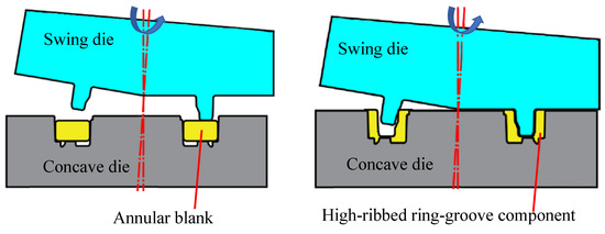
This paper proposes a novel Multi-DoF forming method for high-ribbed ring-groove components, and its principle is illustrated in Figure 1. The swing die is a conical die with an annular boss, which is installed obliquely above the annular blank and makes local contact with the upper surface of the blank. While performing multi-degree-of-freedom envelope motion along the circumferential direction, the swing die moves downward for feeding, and the concave die remains stationary. Under the synergistic action of the swing die and concave die, the annular blank undergoes continuous local plastic deformation with multi-directional metal flow. The metal gradually fills the inner and outer high-rib cavities formed by the two dies, and an annular groove is generated between the inner and outer high ribs, ultimately realizing the overall near-net forming of the high-ribbed ring-groove component. In the forming process, the multi-degree-of-freedom continuous local rolling of the swing die can significantly improve the metal flow capacity and facilitate the precise forming of complex curved surfaces. Therefore, the swing die is adopted to form the complex high-ribbed ring-groove profile, while the non-high-ribbed profile is integrally formed by the fixed concave die. The blank used for forming the component adopts an annular structure, whose inner or outer cylindrical surface is in contact with the profile of the concave die, so as to achieve accurate positioning of the blank inside the die. The assembly relationship among the swing die, concave die and blank is presented in Figure 1.
Figure 1.
Schematic Diagram of Multi-DoF forming Principle for High-Ribbed Ring-Groove Components.
2.2. Finite Element Simulation Model for Multi-DoF Forming of High-Ribbed Ring-Groove Components
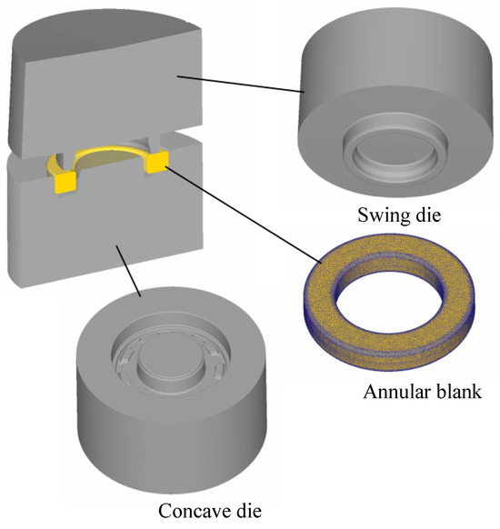
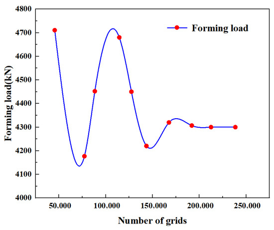
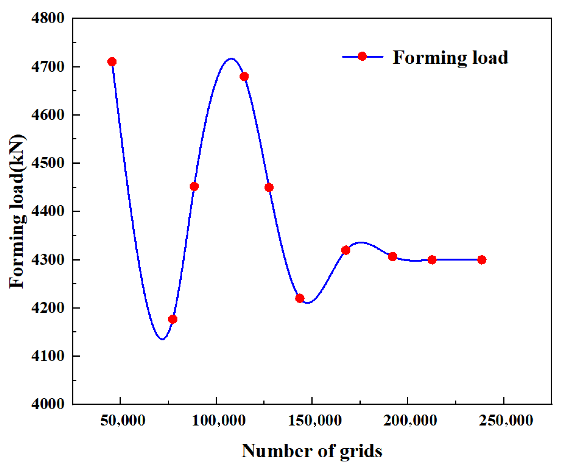
To verify the feasibility of the novel Multi-DoF forming method for high-ribbed ring-groove components and accurately explore the metal flow law and plastic deformation characteristics during the forming process, a three-dimensional finite element simulation model for Multi-DoF forming of high-ribbed ring-groove components is established based on the DEFORM-3D finite element simulation platform, as shown in Figure 2. In the simulation of Multi-DoF forming, the taper angle of the swing die is set to 1.5°. The swing die performs multi-degree-of-freedom envelope motion at a rotational speed of 60 r/min and feeds downward at a velocity of 2 mm/s. The outer diameter is 137 mm, and the inner diameter is 78 mm. The blank is defined as a rigid-plastic body and made of 20CrMnTi alloy steel [33]; the relevant parameters and equations are consistent with those in the literature. The dies are set as rigid bodies and manufactured from Cr12MoV cold-working die steel with high strength and excellent fatigue resistance. The shear friction model is adopted to describe the interfacial friction between the dies and the blank, with the friction coefficient set to 0.12. To balance computational accuracy and efficiency, the blank is meshed with tetrahedral elements, and simulation experiments were carried out with different numbers of grids. The relationship between forming load and the number of grids is shown in Figure 3. The forming load tends to stabilize when the number of grids exceeds 200,000. Therefore, the number of grids is set to 200,000, and the size ratio of the maximum to the minimum grid element is controlled at 3. To ensure the continuity and accuracy of the simulation, the entire forming process is divided into 950 simulation steps, with a displacement increment of 0.02 mm per step. The main process parameters of the finite element simulation model for Multi-DoF forming of high-ribbed ring-groove components are listed in Table 1.
Figure 2.
Finite element simulation model of Multi-DoF forming for high-ribbed ring-groove components.
Figure 3.
Relationship between number of grids and equivalent stress in Multi-DoF forming.
Table 1.
Main parameters of the finite element model for Multi-DoF forming of high-ribbed ring-groove components.
3. Plastic Forming Law of Multi-DoF Forming for High-Ribbed Ring-Groove Components
3.1. Metal Flow Mode in Multi-DoF Forming of High-Ribbed Ring-Groove Components
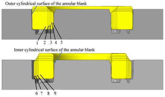
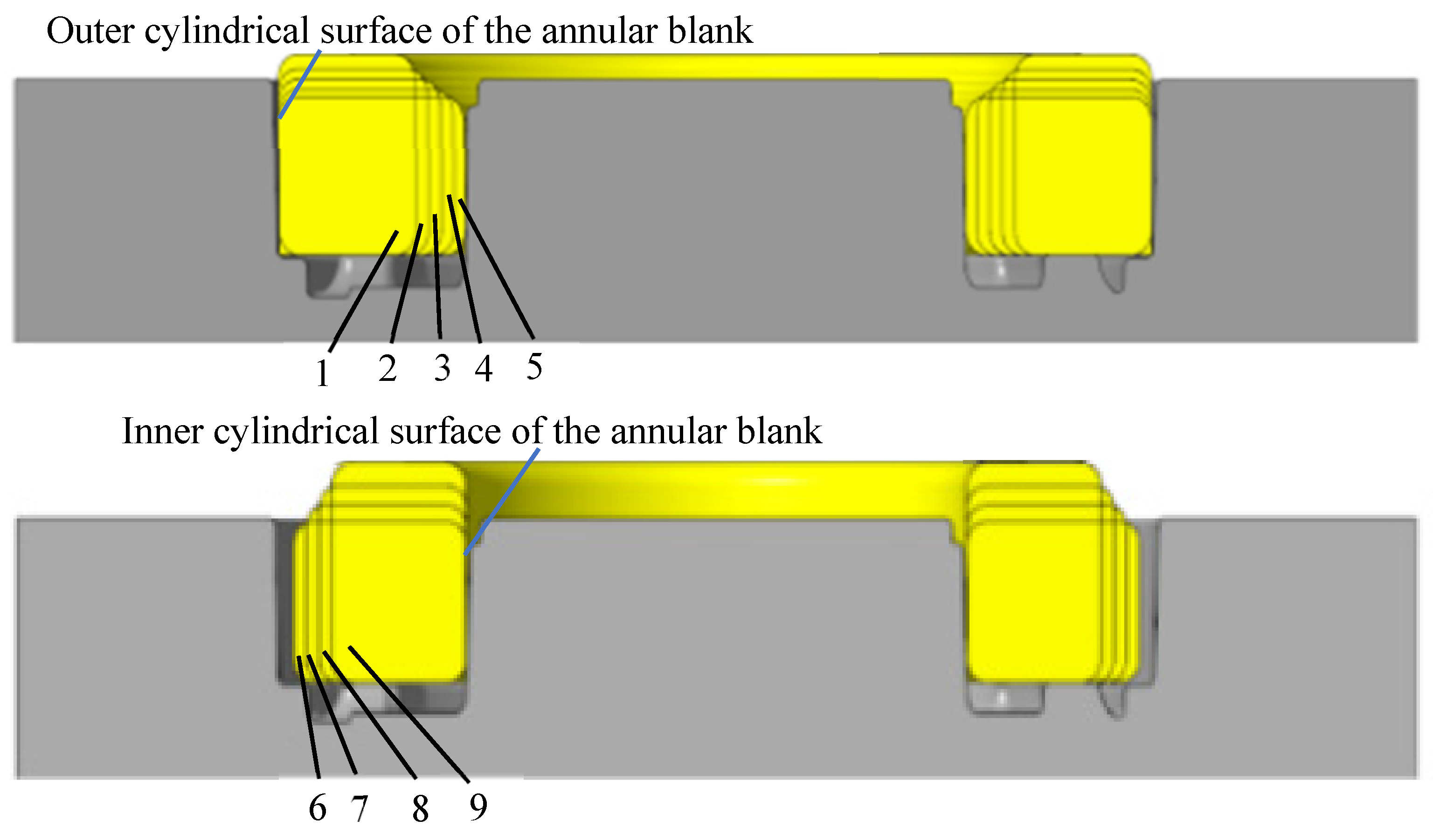
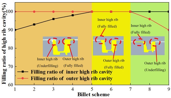
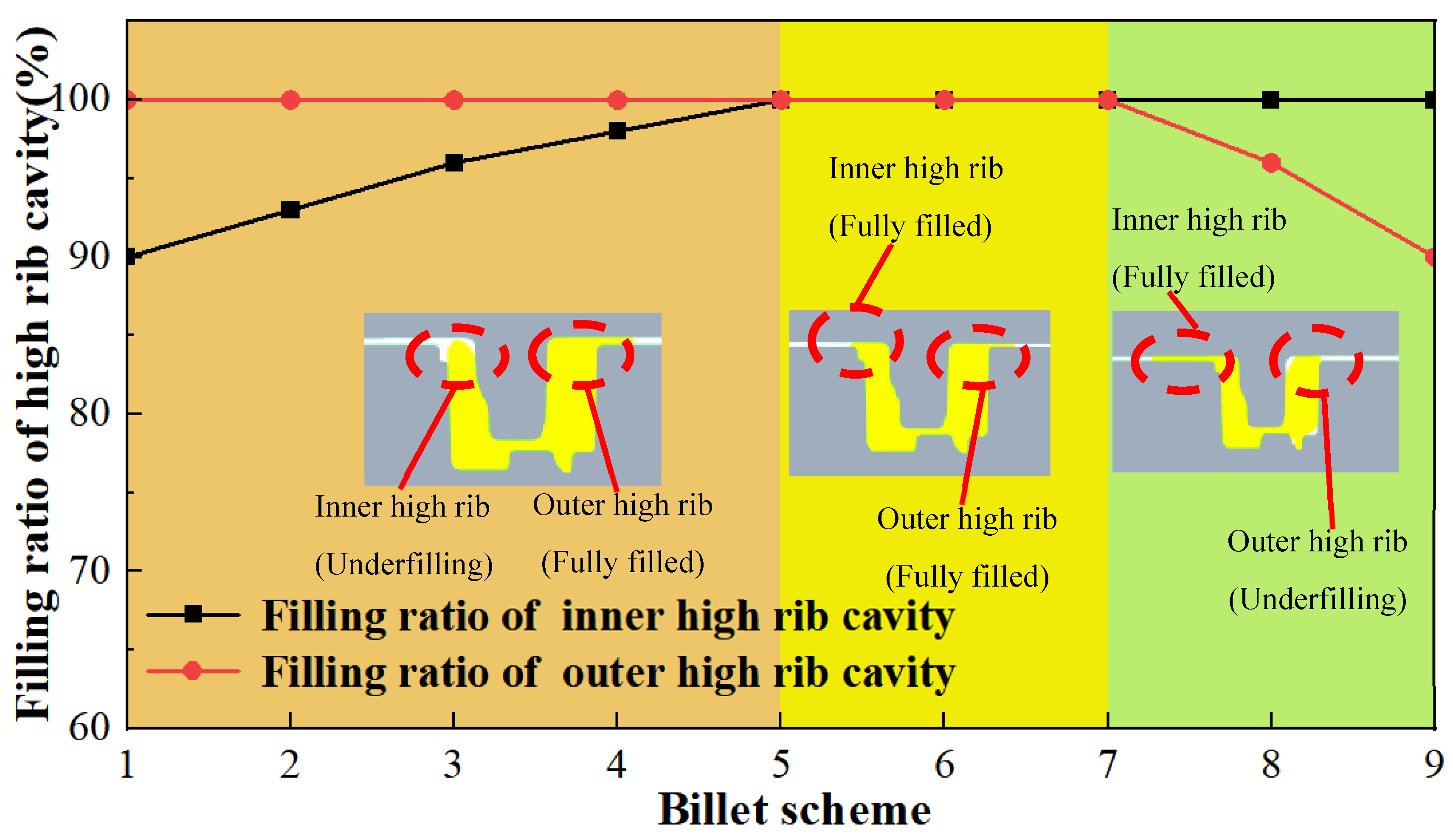
Under the multi-degree-of-freedom envelope motion of the swing die, the metal undergoes complex multi-directional flow, which affects the forming quality of high-rib and ring-groove structures. Blank dimension is a key factor influencing metal flow during Multi-DoF forming of high-ribbed ring-groove components, and different blank sizes lead to distinct metal flow modes. Accordingly, nine blank schemes are designed in this study, as shown in Figure 4. Schemes 1 to 5 adopt the outer cylindrical surface of the annular blank for accurate positioning, with a fixed outer diameter of 137 mm and inner diameters of 94 mm, 90 mm, 86 mm, 82 mm and 78 mm, respectively. Schemes 6 to 9 adopt the inner cylindrical surface of the annular blank for positioning, with a fixed inner diameter of 78 mm and outer diameters of 133 mm, 129 mm, 125 mm and 121 mm, respectively. Based on the finite element simulation model established in Section 2.2, the nine blanks are adopted to conduct a numerical calculation of Multi-DoF forming for high-ribbed ring-groove components. The influence of blank size on the high-rib filling ratio is obtained, as presented in Figure 5.
Figure 4.
Schematic diagram of nine blank schemes for Multi-DoF forming of high-ribbed ring-groove components.
Figure 5.
High-rib filling ratio of high-ribbed ring-groove components under Multi-DoF forming with different blank schemes.
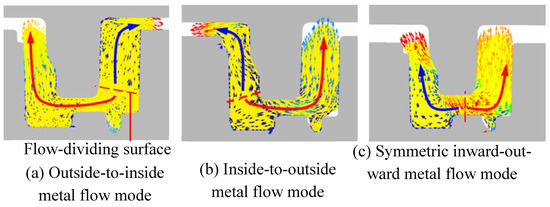
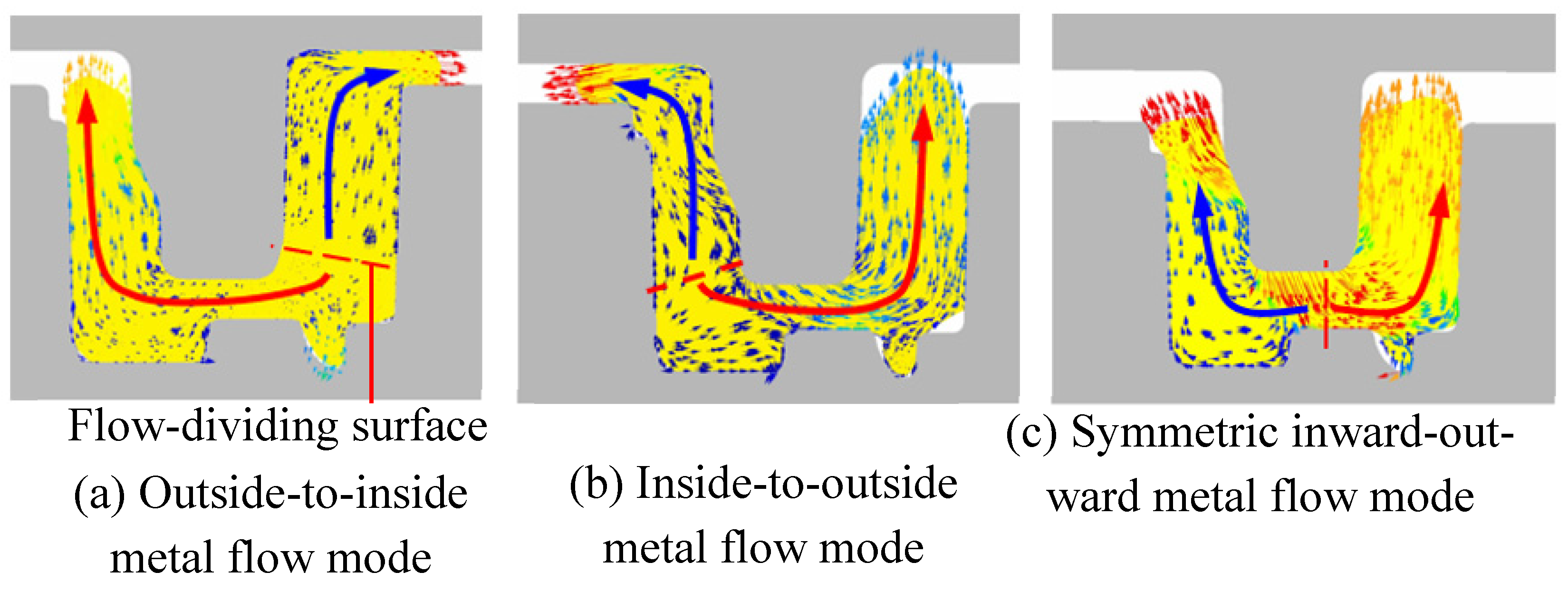
It can be seen from Scheme 1 to Scheme 5 in Figure 5 that when the blank is accurately positioned by its outer cylindrical surface, the outer high ribs are always fully filled, and the filling ratio of the inner high ribs gradually increases as the inner diameter of the blank decreases. This phenomenon occurs because more metal accumulates in the outer high-rib region under this blank design, so the outer high-rib cavities are filled preferentially. After the outer high ribs are fully filled, further feeding of the swing die forces the excess metal in the outer high-rib region to flow from the outer high-rib cavities toward the inner ones. At this time, a flow-dividing surface forms at the bottom of the outer high ribs, and the metal presents an outside-to-inside flow mode, as shown in Figure 6a. In the process of metal flowing from the outer to the inner high-rib cavities, the material has to pass through the bottom fillets of both outer and inner high ribs, resulting in large flow resistance. Consequently, the inner high ribs are difficult to fully fill. As observed from Scheme 7 to Scheme 9 in Figure 4, when the blank is positioned by its inner cylindrical surface, the inner high ribs remain fully filled all the time, while the filling ratio of the outer high ribs gradually declines with the reduction in the blank outer diameter. The underlying mechanism is that more metal concentrates in the inner high-rib region for this blank arrangement, enabling the inner high ribs to be filled first. Once the inner high ribs are completely filled, continuous loading of the swing die drives the redundant metal to flow from the inner high-rib cavities to the outer ones. A flow-dividing surface emerges at the bottom of the inner high ribs, forming an inside-to-outside flow mode, as illustrated in Figure 6b. The metal flow path passes through the bottom fillets of the inner and outer high ribs, generating considerable flow resistance and making it difficult for the outer high ribs to achieve full filling. From Scheme 5 to Scheme 7 in Figure 4, both inner and outer high ribs can be fully filled. The reason is that these three schemes produce a symmetric inward–outward metal flow mode, as shown in Figure 6c. The metal flows symmetrically from the bottom of the ring groove toward both the inner and outer high ribs. Such uniform metal flow ensures complete cavity filling for both inner and outer high ribs.
Figure 6.
Schematic diagram of metal flow modes in Multi-DoF forming of high-ribbed ring-groove components.
3.2. Plastic Deformation Law of Multi-DoF Forming for High-Ribbed Ring-Groove Components
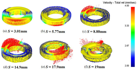
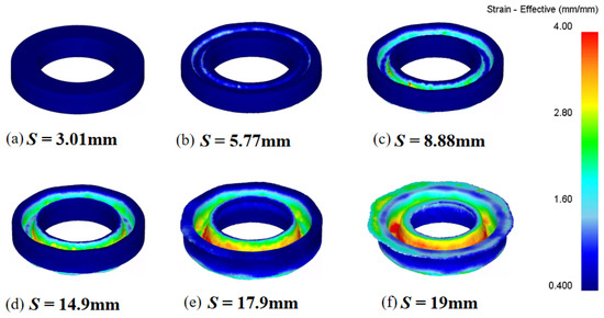
Figure 7, Figure 8, Figure 9 and Figure 10 respectively respectively illustrate the evolution laws of metal flow, plastic strain, metal flow lines and forming load during the Multi-DoF forming of high-ribbed ring-groove components under the symmetric inward–outward metal flow mode. As shown in Figure 6, under the multi-degree-of-freedom envelope action of the swing die, local contact between the swing die and the blank induces continuous local plastic deformation of the blank. The metal flow velocity is higher in the contact region and lower in the non-contact region. Under the rolling action of the swing die, the metal rapidly fills the high ribs, and the heights of the inner and outer high ribs increase synchronously. Finally, a high-ribbed ring-groove component with fully filled inner and outer high ribs is obtained. It can be seen from Figure 8 that the plastic deformation varies significantly in different regions of the component. The equivalent strain is relatively large at the bottom of the high ribs, mainly because the rib bottoms undergo repeated rolling by the swing die and thus accumulate greater plastic deformation. The equivalent strain gradually decreases from the bottom to the top of the high ribs, as the metal at positions closer to the rib top experiences fewer rolling cycles and accumulates less plastic deformation. As presented in Figure 9, the metal flow lines remain continuous throughout the Multi-DoF forming process and are distributed along the contour of the high-ribbed ring-groove component. It is observed from Figure 10 that the forming load of Multi-DoF forming (4300 kN) is remarkably lower than that of integral die forging (19,900 kN). This is because the contact area between the swing die and the blank in envelope forming is only 18–22% of the contact area between the die and the blank in integral die forging.
Figure 7.
Metal flow velocity field during Multi-DoF forming of high-ribbed ring-groove components.
Figure 8.
Equivalent strain distribution of high-ribbed ring-groove components in Multi-DoF forming.
Figure 9.
Metal flow lines during Multi-DoF forming of high-ribbed ring-groove components.
Figure 10.
Comparison of forming load between Multi-DoF forming and die forging for high-ribbed ring-groove components. The green area represents the contact zone, and the yellow area represents the non-contact zone.
4. Stress Optimization Method of Multi-DoF Forming Die for High-Ribbed Ring-Groove Components
4.1. Influence Law of Metal Flow Mode on Stress State of Multi-DoF Forming Die for High-Ribbed Ring-Groove Components
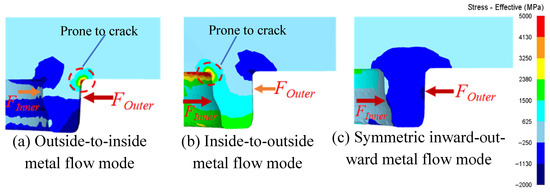
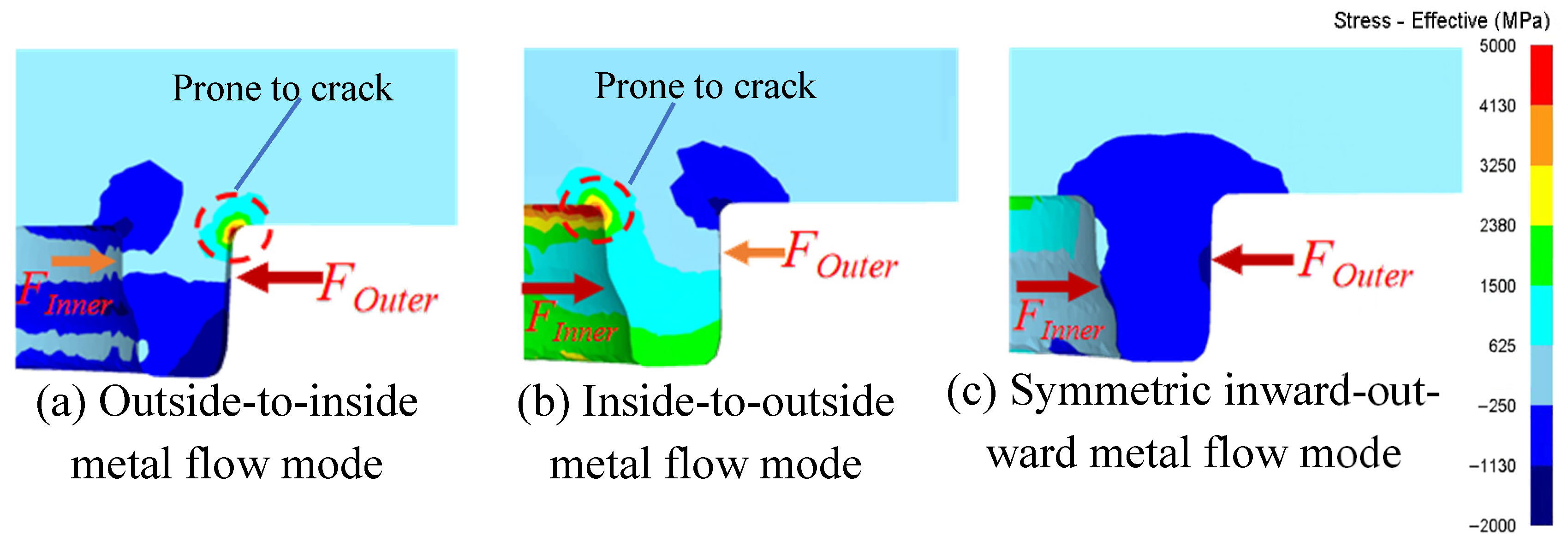
The swing die adopted for forming high-ribbed ring-groove components features an annular boss structure. Unbalanced loading on the inner and outer sides of the annular boss tends to cause cracking in its bottom fillet region. The stress state on the inner and outer sides of the annular boss is determined by the metal flow mode during multi-degree-of-freedom envelope forming of high-ribbed ring-groove components. Accordingly, this section investigates the influence of different metal flow modes on the stress state of the swing die, as shown in Figure 11. Under the outside-to-inside metal flow mode, the outer high ribs are filled first and subjected to large forming pressure, while the inner high ribs are incompletely filled with relatively low contact pressure. Consequently, the load acting on the outer side of the die annular boss is markedly higher than that on the inner side, inducing severe stress concentration at the outer root and increasing the risk of cracking, as shown in Figure 11a. Under the inside-to-outside metal flow mode, the inner high ribs are preferentially filled and bear high forming pressure, whereas the outer high ribs remain incompletely filled with lower pressure. The load on the inner fillet of the swing die boss is much greater than that on the outer side, resulting in serious stress concentration at the inner root and a high tendency toward cracking, as shown in Figure 11b. Under the symmetric inward–outward metal flow mode, the load distribution on the inner and outer sides of the annular boss is balanced. The stress level at both inner and outer root regions remains low, and cracking can be effectively avoided, as shown in Figure 11c.
Figure 11.
Stress distribution nephogram of Multi-DoF forming die for high-ribbed ring-groove components under different metal flow modes.
4.2. Stress Control Method of Multi-DoF Forming Die Based on Metal Flow Mode Regulation
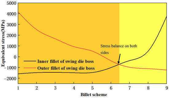
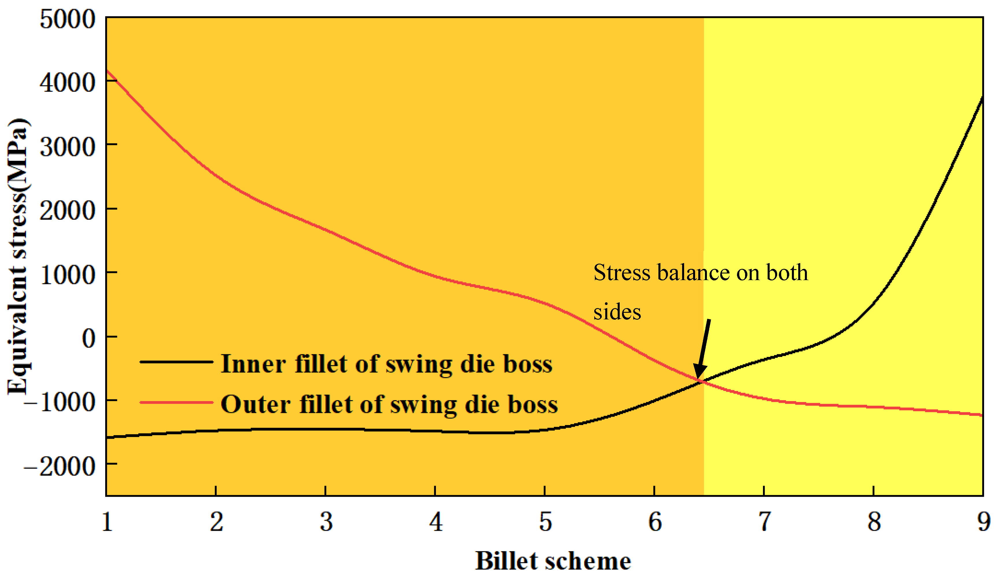
It can be seen from Figure 5 and Figure 6 that adjusting the blank size can regulate the metal flow mode, thereby improving the stress state of the die. On this basis, this paper proposes a die stress control method that optimizes the blank size to regulate the metal flow mode, balances the loading on both sides of the annular boss of the swing die, further improves the die stress distribution, and extends the service life of the die. Figure 12 presents the equivalent stress values at the inner and outer root fillets of the swing die boss under different blank schemes.
Figure 12.
Root stress on inner and outer sides of swinging die boss under different blank schemes.
From Scheme 1 to Scheme 9, the equivalent stress at the inner fillet of the swing die boss gradually increases, while the equivalent stress at the outer root gradually decreases. When the blank outer diameter is 139.04 mm and the inner diameter is 78.58 mm, the equivalent stress at the inner root is equal to that at the outer root, achieving the optimal die stress state. Meanwhile, the blank with this dimension can also ensure complete filling of both the inner and outer high-rib cavities (Figure 5).
5. Experimental Test on Multi-DoF Forming Process of High-Ribbed Ring-Groove Components
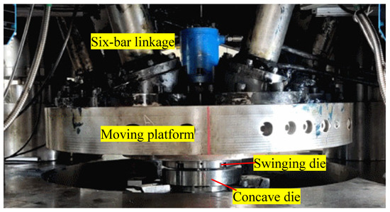
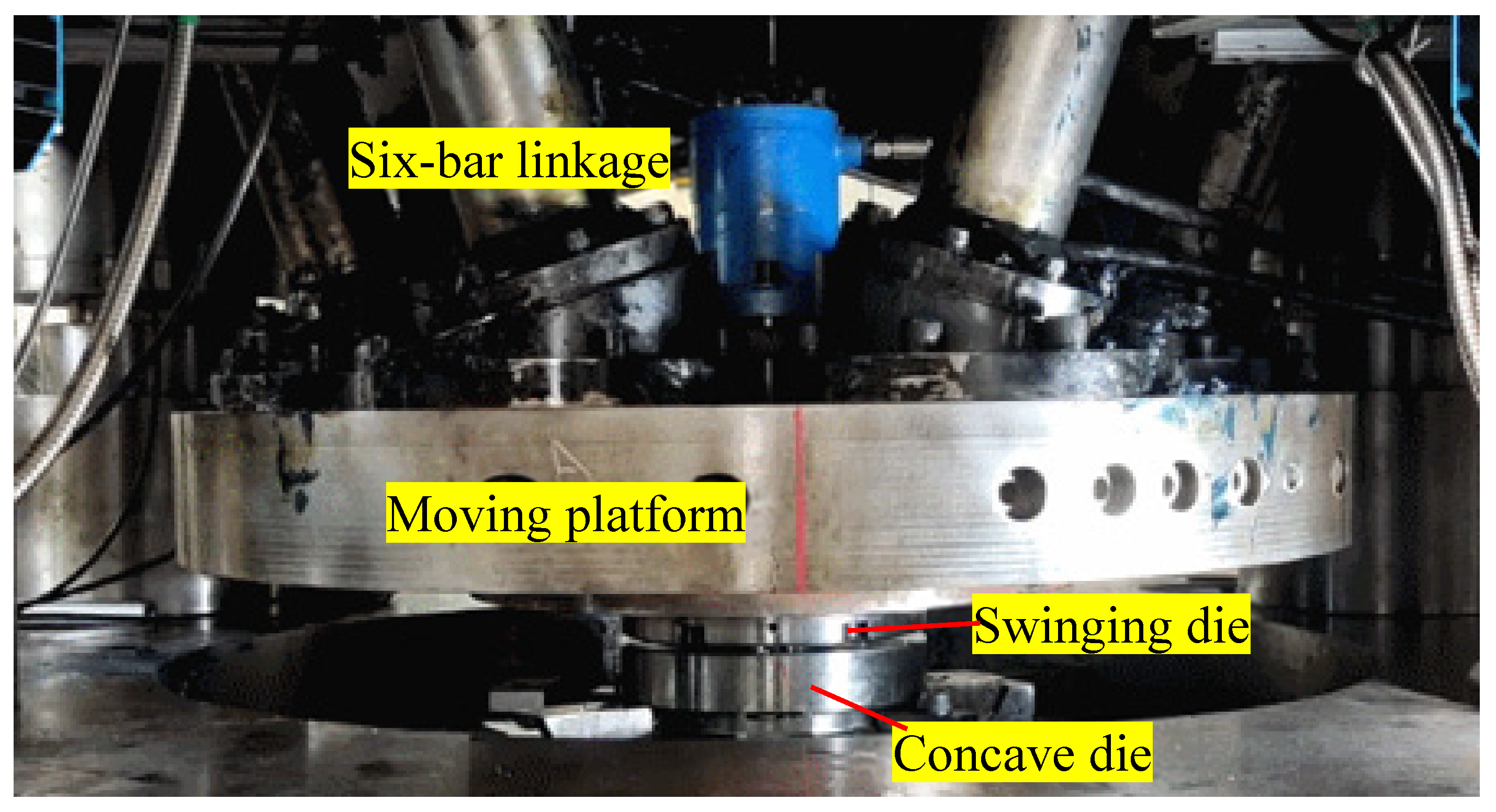
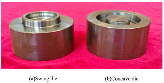
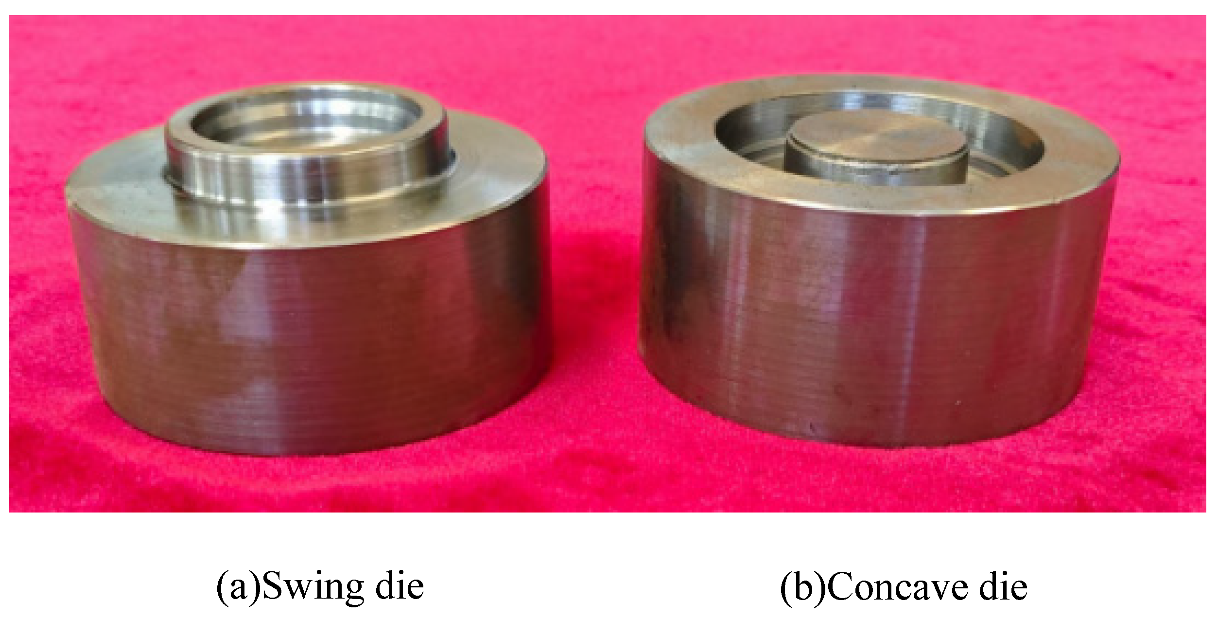
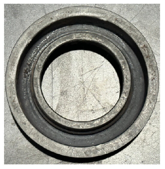
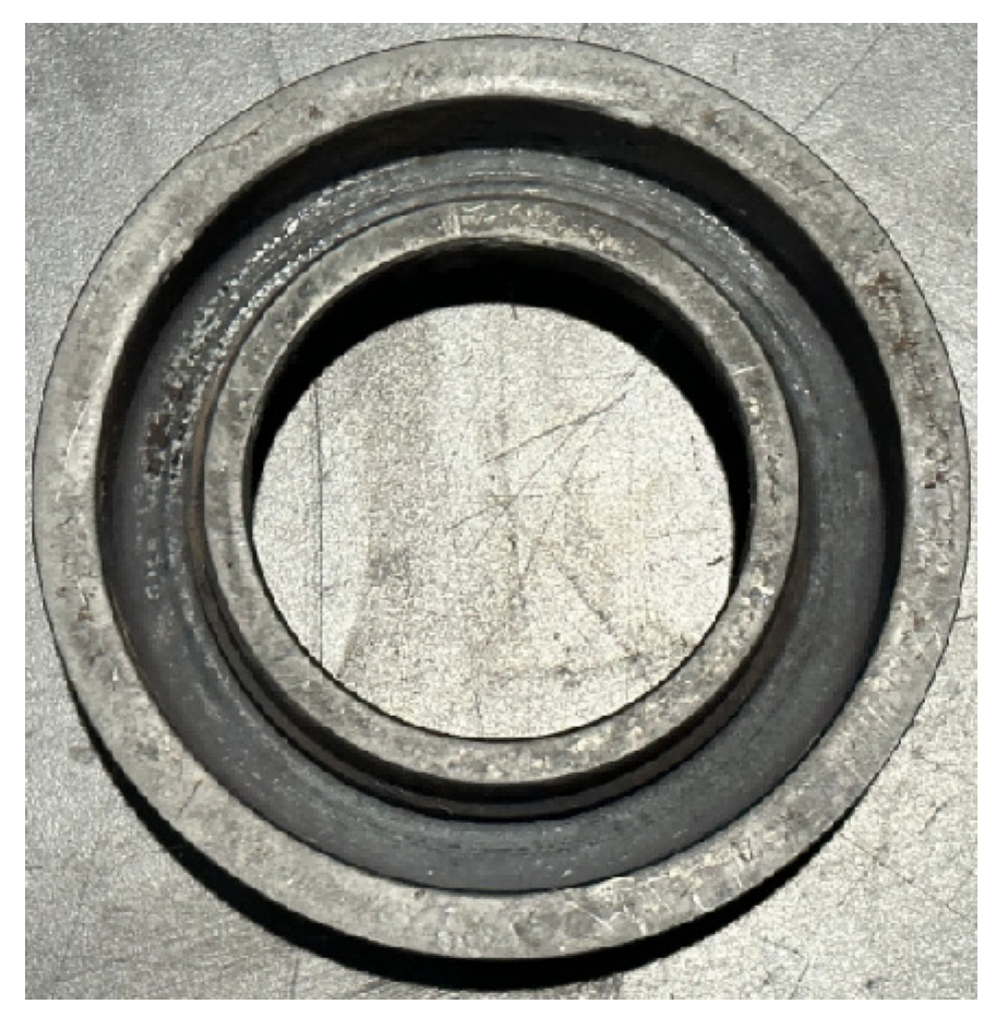
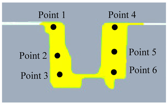
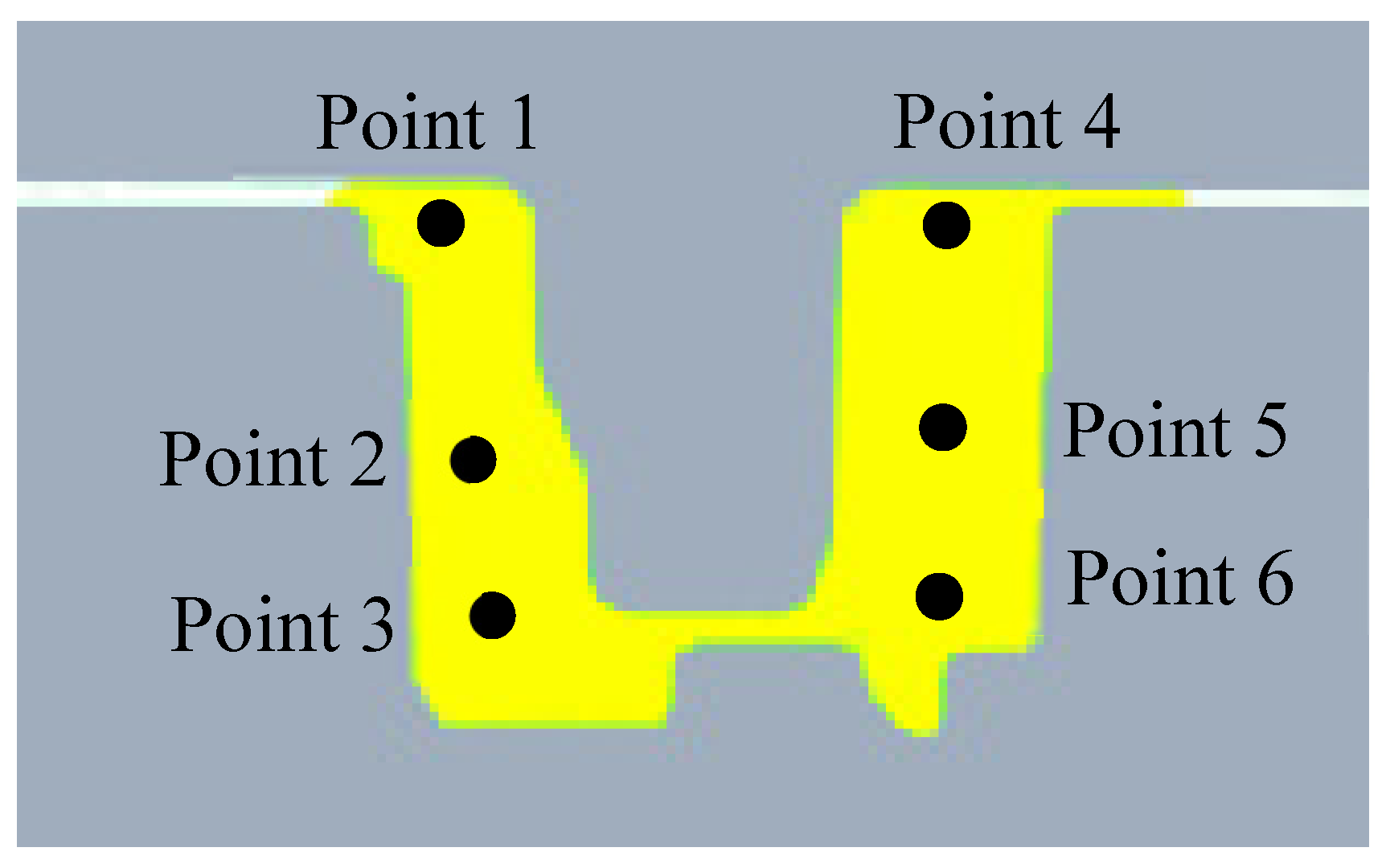
To verify the effectiveness of the Multi-DoF forming process and the die stress control method for high-ribbed ring-groove components, a Multi-DoF forming experimental platform was established, and experimental verification tests of the forming process were carried out. Figure 13 shows six-linkage Multi-DoF forming equipment with a maximum forming force of 800 tons. The swing die is mounted on the moving platform, which can perform multi-degree-of-freedom envelope motion driven coordinately by the six-linkage mechanism. The experimental parameters for Multi-DoF forming of high-ribbed ring-groove components are consistent with the finite element simulation parameters listed in Table 1. Figure 14 presents the swing die and concave die used in the forming test, and Figure 15 shows the blank and experimental workpiece of the high-ribbed ring-groove component after Multi-DoF forming. It can be observed from Figure 15 that both the inner and outer high ribs of the component are fully filled, and the inner/outer rib height and thickness are measured, as shown in Table 2. The error of the inner high-rib thickness is −0.15 mm to +0.1 mm. The error of the inner high-rib height is −0.5 mm to +0.7 mm. The error of the outer high-rib thickness is −0.05 mm to +0.1 mm. The error of the outer high-rib height is −0.6 to +0.9 mm, verifying simulation accuracy, and no failure occurs on the swing die (Figure 14). To investigate the hardness distribution of a Multi-DoF forming high-girdle ring-groove component, six characteristic points were selected on its cross-section (Figure 16), and their hardness values were measured as shown in Table 3. The high-ribbed ring-groove component undergoes continuous plastic deformation during forming, and the hardness at the bottom of the high ribs is higher than that at the top. The results verify the effectiveness of the proposed Multi-DoF forming method and the die stress control method for high-ribbed ring-groove components.
Figure 13.
Multi-DoF forming equipment for high-ribbed ring-groove components.
Figure 14.
Test die for Multi-DoF forming of high-ribbed ring-groove components.
Figure 15.
Test specimens of high-ribbed ring-groove components by Multi-DoF forming.
Figure 16.
Characteristic points on the cross-section of high-ribbed ring-groove component.
Table 2.
Cross-sectional hardness distribution of high-ribbed ring-groove components formed by multi-degree-of-freedom forming.
Table 3.
Comparison of experimental results on Multi-DoF forming of high-ribbed ring-groove components.
6. Conclusions
(1) A novel Multi-DoF forming method for high-ribbed ring-groove components is innovatively proposed, which achieves the near-net-shape plastic forming of high-ribbed ring-groove components with fully filled inner and outer ribs and qualified forming quality.
(2) The influence of blank dimensions on the filling effect of high-ribbed ring-groove components is revealed, and three typical metal flow modes are determined, namely outside-to-inside flow, inside-to-outside flow, and symmetric inward–outward flow. A feasible blank design window is established to ensure full cavity filling.
(3) The evolution laws of metal flow, plastic strain, metal flow lines and forming load during Multi-DoF forming are clarified. The Multi-DoF forming process significantly improves metal flow ability, generates continuous and complete metal flow lines along the component profile, and reduces the maximum forming load to 4300 kN, which is only about 21.6% of that in conventional integral die forging.
(4) A die stress optimization method is proposed based on regulating metal flow modes via blank size optimization. This method balances the loading distribution on the inner and outer sides of the swing die annular boss, eliminates stress concentration at the die fillets, and effectively improves die service life.
(5) The forming experiments demonstrate that the simulated and measured cross-sectional dimensions of the component are in good agreement, with a marginal error within ±0.15 mm. The hardness distribution matches the plastic strain evolution, which validates the accuracy of the finite element model and the effectiveness of the proposed process optimization method.
Author Contributions
Conceptualization, B.Z. and Y.W.; methodology, B.Z.; software, X.W.; validation, B.Z., Y.W. and X.W.; formal analysis, B.Z.; investigation, B.Z.; resources, Y.W.; data curation, Y.W.; writing—original draft preparation, B.Z.; writing—review and editing, W.Z.; visualization, W.Z.; supervision, B.Z.; project administration, W.Z.; funding acquisition, W.Z. All authors have read and agreed to the published version of the manuscript.
Funding
This research was funded by the Innovative Research Team Development Program of the Ministry of Education of China (No. IRT17R83) and the National Natural Science Foundation of China (No. U21A20131, No. 52575437 and No. 52005375).
Data Availability Statement
The original contributions presented in this study are included in the article. Further inquiries can be directed to the corresponding author.
Conflicts of Interest
The authors declare no conflict of interest.
References
- David, H.; Anders, E.; Tore, V. Railway wheel failure caused by flange crack, part 1: Background and failure analysis. Eng. Fail. Anal. 2026, 191, 110770. [Google Scholar] [CrossRef] [Scilit]
- Ren, G.; Zhou, J.; Cui, Q. Vibration and noise of two-stage gear reducer considering tooth surface friction. J. Braz. Soc. Mech. Sci. Eng. 2026, 48, 326. [Google Scholar] [CrossRef] [Scilit]
- Guo, Q.L.; Qian, Z.; Huang, E. Leakage performance of floating ring seal in cold/hot state for aero-engine. Chin. J. Aeronaut. 2019, 32, 2085–2094. [Google Scholar] [CrossRef] [Scilit]
- Zhu, K.; Jun, L. Physics-Guided Deep Network for Milling Dynamics Prediction. Engineering 2025, 55, 71–85. [Google Scholar] [CrossRef] [Scilit]
- Voigt, R.; Marin, F.; Basso, I.F.; Mikowski, A.; Rodrigues, A.R.; Xavier, F.A.; de Souza, A.F. Ploughing and shearing machining mechanisms in ball-end milling of free-form surfaces. Int. J. Adv. Manuf. Technol. 2026, 142, 3699–3718. [Google Scholar] [CrossRef] [Scilit]
- Lyu, W.; Liu, Z.; Tang, W.; Wang, B.; Liang, X.; Zhao, J.; Lu, C. High performance machining based on fretting wear mechanism of slot milled surfaces. Tribol. Int. 2026, 217, 111615. [Google Scholar] [CrossRef] [Scilit]
- Hirt, G.; Bambach, M.; Lohmar, J.; Guvenc, O.; Henke, T.; Schwich, G. Materials modelling in industrial bulk metal forming processes and process chains. Comput. Methods Mater. Sci. 2015, 15, 5–12. [Google Scholar] [CrossRef] [Scilit]
- Deng, J.C.; Shen, Z.J.; Huang, Z.R.; Su, Y. Effect of static pressure during ultrasonic surface rolling process on surface integrity and fatigue performance of a die-forged 2014 aluminum alloy aircraft wheel. Mater. Today Commun. 2025, 49, 114170. [Google Scholar] [CrossRef] [Scilit]
- Sharma, A.; Hussain, V.; Kumar, P.A.; Raj, M.P. Failure mode and effects analysis of forging die design: An integrated approach. Mater. Today Proc. 2022, 62, 4041–4045. [Google Scholar] [CrossRef] [Scilit]
- Zhang, J.; Guo, X.F.; Huang, S.; Wang, J.; Yang, J.; Zhang, Z.Y. Research on key technologies of rolling and bulging process and equipment for aluminum alloy ring forgings with ultra-large diameter. Suxing Gongcheng Xuebao/J. Plast. Eng. 2024, 31, 99–107. [Google Scholar]
- He, J.; He, F.Y.; Xu, L.; Dong, J. Research Progress on Ring Rolling Technology of superalloy ring forging. Rare Met. Mater. Eng. 2021, 50, 1860–1866. [Google Scholar]
- Lin, L.F.; Wang, B.Y.; Guo, W.; Peng, W.F.; Wu, X.C.; Huang, M.H. Modeling and Analysis of Central Damage of Cross Wedge Rolling Railway Axles Based on Hybrid Damage Criterion. J. Mech. Eng. 2025, 61, 141–152. [Google Scholar] [CrossRef] [Scilit]
- Wang, B.Y.; Shen, J.X. Precise Rolling Alignment Curve for Inner Right-Angle Small Steps in Cross-Wedge Rolling. J. Univ. Sci. Technol. Beijing 2022, 44, 59–67. [Google Scholar]
- Zhang, X.Y.; Yang, Y.H.; Zheng, A.L.; Liu, C.; Lai, F. FEM-guided parameter tuning for crack-free radial forging of large-diameter tungsten bars. Int. J. Refract. Met. Hard Mater. 2026, 135, 107522. [Google Scholar] [CrossRef] [Scilit]
- Yang, Y.Z.; Yang, C.; Xu, C. In homogeneous deformation in the radial direction of the cold radial forged 30SiMn2MoVA steel tube. Mater. Chem. Phys. 2024, 327, 129899. [Google Scholar] [CrossRef] [Scilit]
- Pater, Z.; Tomczak, J.; Shu, X.; Li, Z. Comparative analysis of cross-wedge rolling methods. Adv. Sci. Technol. Res. J. 2026, 20, 423–435. [Google Scholar] [CrossRef] [Scilit]
- Zhang, H.R.; Zhan, M.; Zheng, Z.B.; Li, R. Development and Challenge of Forming Manufacturing Technologies for Aerospace Large-Scale Thin-Wall Axisymmetric Curved-Surface Component. J. Mech. Eng. 2022, 58, 166–185. [Google Scholar] [CrossRef] [Scilit]
- Li, J.L.; Wang, A.; Lu, J.L.; Li, Z.; Chen, P.; Sun, C.; Pan, L.; Xuan, L.; Zhang, L. Research on bonding mechanism of bimetallic composite shaft by cross-wedge rolling. J. Mater. Res. Technol. 2025, 36, 8048–8061. [Google Scholar] [CrossRef] [Scilit]
- Liu, Y.; Wang, M.Y.; Ma, Y.M.; Yan, M.; Huang, H.-G. Optimization of spinning forming mold for thin-walled semi-flexible stainless steel bellows. Int. J. Adv. Manuf. Technol. 2026, 143, 625–642. [Google Scholar] [CrossRef] [Scilit]
- Sergio, E.; Pablo, C.; Casimir, C.; Puigjaner, B.; Cabello, D.; Cabrera, J.M. Study of the effect of the process parameters on the forming limit in shear spinning processes. Int. J. Adv. Manuf. Technol. 2025, 136, 3303–3314. [Google Scholar] [CrossRef] [Scilit]
- Gao, P.F.; Gong, Y.L.; Ren, Z.P.; Zhan, M. A new spinning-extrusion forming technology for the inner-ribbed component. Int. J. Mech. Sci. 2024, 279, 109494. [Google Scholar] [CrossRef] [Scilit]
- Han, X.H.; Min, Y.L.; Zhuang, W.H.; Hua, L.; Tian, D.; Deng, Z.; Liu, N. Radial envelope forming mechanism and process design method for cylindrical rings with thin wall and high web ribs. Chin. J. Aeronaut. 2023, 36, 461–476. [Google Scholar] [CrossRef] [Scilit]
- Han, X.H.; Hua, L.; Tian, D.Y.; Zhuang, W. Modelling and analysis of metal flowing behaviors in constraining ring rolling of tapered ring with thin wall and three high ribs. Chin. J. Aeronaut. 2023, 36, 476–492. [Google Scholar] [CrossRef] [Scilit]
- Zhang, Z.; Li, G.; Wang, Q.; Yu, J.; Xue, Y.; Chen, Z. Multi-directional loading rotary extrusion forming technology and equipment. J. Mech. Eng. 2023, 59, 264–271. [Google Scholar]
- Song, S.; Jia, X.; Sun, Z.C. Study on the Surface Forming Quality of FeMnSi/NiTiNb Composite Pipe by Rotary Extrusion. Mater. China 2025, 44, 785–792. [Google Scholar]
- Hua, L.; Feng, W.; Han, X.H.; Zhuang, W.H. Research and Application of Theory, Technology and Equipment for Precision Plastic Forming of Gears. J. Plast. Eng. 2024, 31, 56–73. [Google Scholar]
- Lei, Y.D.; Zhan, M.; Fan, X.G.; Zhang, Y.Q.; Niu, H.T.; Bai, D.N.; Gao, P.F.; Zheng, Z.B. A review on manufacturing technologies of thin-walled components with ribs. J. Northwest. Polytech. Univ. 2022, 40, 1–17. [Google Scholar] [CrossRef] [Scilit]
- Zhan, M.; Dong, Y.D.; Zhai, Z.L.; Fan, X.G.; Shi, Z.P.; An, Q. Review on Fast Numerical Simulation Method for Plastic Forming. J. Mech. Eng. 2022, 58, 2–20. [Google Scholar] [CrossRef] [Scilit]
- Li, X.T.; Sun, C.Y.; Qian, L.; Sun, J.; Liu, J. Flow defects of rib-web components in isothermal local-loading forming process. Int. J. Adv. Manuf. Technol. 2023, 125, 3417–3429. [Google Scholar] [CrossRef] [Scilit]
- Yang, C.; Wei, K.; Wang, F.B.; Hou, Y.; Chen, W. Investigation and prediction of material transfer in transitional region under local loading forming of large-scale rib-web components from perspective of multi-stage stress states. Chin. J. Aeronaut. 2026, 39, 104009. [Google Scholar] [CrossRef] [Scilit]
- Hu, Y.X.; Han, X.H.; Hua, L.; Zhuang, W. Metal flow and rib growth model in multi-DOF envelope forming process of component with thin wall and high web ribs. Thin-Walled Struct. 2025, 209, 112906. [Google Scholar] [CrossRef] [Scilit]
- Jin, Q.; Han, X.; Hua, L.; Zhuang, W.; Feng, W. Process optimization method for cold orbital forging of component with deep and narrow groove. J. Manuf. Process. 2018, 33, 161–174. [Google Scholar] [CrossRef] [Scilit]
- Deng, X.B.; Hua, L.; Han, X.; Song, Y. Numerical and experimental investigation of cold rotary forging of a 20CrMnTi alloy spur bevel gear. Mater. Des. 2011, 32, 1376–1389. [Google Scholar] [CrossRef] [Scilit]

Disclaimer/Publisher’s Note: The statements, opinions and data contained in all publications are solely those of the individual author(s) and contributor(s) and not of MDPI and/or the editor(s). MDPI and/or the editor(s) disclaim responsibility for any injury to people or property resulting from any ideas, methods, instructions or products referred to in the content. |
© 2026 by the authors. Licensee MDPI, Basel, Switzerland. This article is an open access article distributed under the terms and conditions of the Creative Commons Attribution (CC BY) license.