


Abstract
Lightweight materials with improved strength characteristics are increasingly required in aerospace, automotive, impact protection, and vibration damping applications to enhance structural efficiency and service life. Although aluminum metal foams have been found to be promising lightweight cellular materials, their load-bearing performance is rather limited, thus limiting their use for high-performance structural applications. The composite metal foams in the present study were produced by CaCO3 as foaming agent and AA7075 as the base material by gas-releasing particle decomposition method, in which the foaming agent is transformed into CO2 gas to generate pores during foaming. Cell size distribution analysis, density, and energy-dispersive spectroscopy were used to investigate the composite foams containing 0, 1, 2 and 3 wt.% Si3N4, while quasi-static uniaxial compression testing was employed to measure the compressive strength of these foams. Si3N4 of 2 wt.% and 3 wt.% resulted in better pore refinement and uniformity of cells, as revealed in the microstructural analysis. The density was raised from 0.21 to 0.61 g/cm3 by reinforcement addition. The compression strength increased from 7.85 to 23.64 MPa, while energy absorption increased from 5.10 to 20.52 MJ/m3 for foams containing 0 and 3 wt.% Si3N4, respectively. The yield strength also improved from 4.92 to 15.98 MPa, and the plateau stress from 7.37 to 22.57 MPa. Improved mechanical behavior is due to the following: refinement of pores, thickness of the ligaments, more compact structure, and load transfer in the cellular structure.
1. Introduction
The increasing requirement for enhancing mechanical competence while reducing the weight of materials, along with effective energy absorption, has yielded intensive studies on metallic systems, especially aluminum-based materials. Aluminum alloys have been extremely popular in the aerospace, automobile and structural industries, owing to their low density, high specific strength, and good corrosion resistance [1,2,3]. Within this context, recent interest has turned to metallic foams as a new class of materials, due to their cellular nature, which offers low weight coupled with multifunctional capabilities such as energy absorption, vibration dampers, and thermal insulation [4,5,6,7].
Metal foams are usually prepared through melt foaming, powder metallurgy, and precursor-based fabrications, which result in porous structures with overall performance highly depending on cell morphology, such as pore-size, distribution, and cell wall thickness [8,9,10,11]. Metal foams with different pore connectivity can be classified as open-cell and closed-cell foams, where open-cell foams are mainly used in filtration and heat transfer applications, and closed-cell foams have stronger structural integrity that are more suitable for load-bearing and impact applications [12,13,14]. Metallic foams usually exhibit three stages of deformation under compression. An initial elastic region is followed by a plateau region due to progressive cell collapse, and finally by densification [15,16,17].
Relative density and internal cell structure both play a key role in determining the mechanical behavior of metal foams. The strength and stability of metal foams are generally believed to improve with uniform pore distribution and well-developed cell walls, while irregular structure and defects caused by processing procedures will greatly decrease the load-bearing capability [18,19]. These defects usually act as stress concentrators to induce early damage in the compression process.
The fabrication process can have a great influence on the morphology and properties of metal foams. For instance, the coating thickness, slurry viscosity, foaming temperature and precursor densification are considered to be key parameters to controlling the pore morphology and microstructural evolution caused by lost foam casting and powder metallurgy processes [19,20,21]. Numerous reinforcement techniques have been investigated to improve the mechanical properties of aluminum foams. The inclusion of ceramic particles, such as SiC and Al2O3, can improve the load transfer and stabilize the foam structure, resulting in improved mechanical properties [22,23,24,25]. Recent research on ceramic particle reinforcements has further increased the energy absorption and plateau stress of the foams due to improved interfacial bonding and increased nucleation sites [26,27]. In addition to melt foaming and powder metallurgy routes, replication-based methods have also been used for producing metallic foams with controlled pore architecture. In this method, a removable template or pre-designed polymer structure is replicated by molten metal infiltration or casting, followed by template removal to obtain a porous metallic structure [28]. Although some progress has been made, the correlation between cell morphology and compressive mechanical performance of metallic foams is still not clear. Most research only focuses on the processing or the effect of reinforcements independently. The correlation between the pore structure (i.e., cell size, distribution and wall thickness) and mechanical properties has not been demonstrated. Further, the high-strength aluminum alloy, AA7075, has been receiving limited attention in foam fabrication. Theinfluence of ceramic reinforcements in strengthening cell walls and stabilizing the foam remains insufficiently explored compared to Al-Si and A356 alloys.
Ceramic-particle reinforcement is a well-established approach to improving the stability and mechanical performance of aluminum metal foams [29,30,31]. In composite and nanocomposite metal foams, micro- and nano-sized reinforcement phases can strengthen the metallic cell walls and cell edges, thereby improving stiffness and load-bearing capacity [30,32]. In addition to their reinforcing role, ceramic particles can also act as foam-stabilizing constituents during melt foaming [33,34]. Particles such as SiC and Al2O3 are known to migrate preferentially toward the liquid/gas interface, increase melt viscosity, reduce liquid drainage, suppress bubble coalescence, and improve the uniformity of the cellular structure [34,35,36,37]. Accordingly, several ceramic reinforcements, including SiC, Al2O3, TiB2, Y2O3, and AlN, have been explored in aluminum and aluminum-alloy foams [38,39,40,41].
However, the literature also shows that the effect of ceramic reinforcement is not universal and depends strongly on the matrix alloy, reinforcement type, particle size, reinforcement content, foaming route, relative density, and pore morphology [42,43]. For example, SiC-reinforced foams can show improved yield stress and energy absorption, but increased ceramic content may also promote brittle collapse and stress fluctuations in the plateau region [44,45]. Al2O3- and TiB2-reinforced systems have also shown improved compressive response in some cases, but the reported performance is strongly influenced by porosity fraction, particle distribution, interfacial bonding, and processing route [46,47,48]. Thus, although the general concept of ceramic particle-reinforced aluminum foams is well established, the response of each alloy reinforcement–foaming agent system must be examined independently [42,43].
Most previous studies on ceramic-reinforced aluminum foams have focused on commercially pure aluminum, Al–Si alloys, A356, AlSi7, AlSi9Mg, or Zn–Al alloy systems, with SiC, Al2O3, and TiB2 being the most frequently investigated reinforcements [46,47]. In comparison, limited attention has been given to closed-cell composite foams based on high-strength AA7075 alloy [48,49]. AA7075 is attractive for lightweight structural applications because of its high strength-to-weight ratio and precipitation-hardenable composition [50]. Nevertheless, its behaviour in cellular form, especially when reinforced with Si3N4 particles and foamed using CaCO3, remains insufficiently understood [47,48,49,50].
Si3N4 is a promising reinforcement for aluminum composite foams because it combines high hardness, high elastic modulus, thermal stability, and relatively low density [51,52,53]. These characteristics are expected to improve the load-bearing ability of foam ligaments and delay local cell wall collapse during compression [54,55]. However, compared with SiC [56] and Al2O3, the role of Si3N4 in controlling pore morphology, relative density, densification strain, plateau stress, and energy absorption of aluminum foams has not been systematically established. This gap is particularly important for AA7075-based foams, where the matrix alloy itself provides a high-strength skeleton, but foam stability and collapse behavior remain strongly dependent on pore morphology and reinforcement distribution [57,58,59,60].
The present study addresses this gap by fabricating AA7075-based closed-cell composite foams containing 0, 1, 2, and 3 wt.% Si3N4 using CaCO3 as the gas-releasing foaming agent and Mg as a wettability enhancer. The scientific contribution of this work lies in establishing a quantitative structure–property relationship between Si3N4 content, cellular morphology, density, relative density, porosity, yield strength, plateau stress, compressive strength, densification strain, and energy absorption behavior. Therefore, the novelty of this study is not the general use of ceramic reinforcement in aluminum foams, but the systematic evaluation of the AA7075-Si3N4-CaCO3 foam system and the clarification of how low Si3N4 additions modify foam stability and compressive collapse response.
To the best of the authors’ knowledge, a systematic investigation of CaCO3-foamed AA7075 closed-cell composite foams reinforced with low Si3N4 contents has not been previously reported. The present work differs from earlier SiC-, Al2O3-, and TiB2-reinforced aluminum foam studies by focusing on a high-strength AA7075 matrix and by correlating low Si3N4 additions with foam morphology, relative density, densification strain, plateau stress, and energy absorption. This provides new insight into the role of Si3N4 as both a cell wall-strengthening phase and a foam-stabilizing constituent in AA7075-based composite metal foams.
2. Materials and Methods
2.1. Materials
The selection of aluminum alloy AA7075 as base material is due to its high strength-to-weight ratio, high mechanical properties, and suitability as structural material. Zinc, magnesium, and copper are the main alloying elements in this alloy, which provide the alloy with excellent strength due to the precipitation hardening mechanism. Si3N4 particles were chosen as the reinforcing material due to their high hardness, high temperature stability and very good wear resistance. Addition of ceramic particles to the aluminum matrix is expected to improve the mechanical properties through better load transfer and reinforcement of cell walls in the foam structure. The Si3N4-reinforcing particles had an average size of less than 10 μm to prevent their agglomeration during processing and promote uniform distribution in the matrix. The composition of AA7075 alloy used in the present study is listed in Table 1.
Table 1.
Chemical composition of AA7075.
To verify the chemical composition of the base material, Energy-Dispersive X-ray Spectroscopy (EDS) analysis was performed on the AA7075 alloy using a scanning electron microscope. The microstructural characterization of the AA7075 alloy and Si3N4 reinforcement particles was carried out using a TESCAN MIRA Scanning Electron Microscope (SEM) (Equipment Code: 037802, TESCAN GROUP, Brno, Czech Republic). Prior to examination, the specimens were cleaned and prepared according to standard metallographic procedures. SEM observations were performed under suitable accelerating voltage and working distance conditions to obtain clear microstructural features. EDS analysis (Figure 1) confirmed the presence of major alloying elements such as Al, Zn, Mg, and Cu within the specified range. The results validate that the base material corresponds to the standard composition of the alloy.
Figure 1.
EDS spectrum of AA7075 alloy showing the presence of major elements.
The morphology of the Si3N4 particles was examined using scanning electron microscopy (SEM), as shown in Figure 2a. The particles exhibit irregular shapes with fine size distribution, which supports effective dispersion within the aluminum matrix. The elemental composition was verified using EDS, as shown in Figure 2b. The presence of silicon (Si) and nitrogen (N) confirms the Si3N4 reinforcement, while the absence of impurity peaks indicates good purity.
Figure 2.
(a) SEM image of the Si3N4 particles; (b) EDS analysis of the Si3N4 particles.
CaCO3 was selected as the foaming agent because it can release CO2 gas during high-temperature melt processing, thereby generating pores within the molten AA7075 alloy. Compared with TiH2, which is widely used as a foaming agent but often requires pre-treatment to control hydrogen release, CaCO3 is inexpensive, easily available, safer to handle, and suitable for gas-releasing particle decomposition during high-temperature foaming. The use of CaCO3 is also compatible with the processing temperature used in the present work. In addition, CaCO3-derived residues and oxide-containing films formed during foaming may contribute to foam stabilization by increasing melt resistance to drainage and reducing bubble coalescence.
The selected reinforcing material was Si3N4 due to its high hardness, high elastic modulus, good thermal stability, and relative low density. The properties are useful for enhancing the rigidity and resistance against collapse of the cell walls and ligaments of aluminum composite foams. Fine Si3N4 particles may also affect the melts’ viscosity and prevent overgrowth of bubbles during foaming, which helps refine pores. In addition, the role of Si3N4 on the morphology and the compressive behavior of AA7075 closed-cell composite foams is less studied than with other materials that have been studied such as SiC, Al2O3, and TiB2. Hence, CaCO3 and Si3N4 were chosen to design and test an AA7075-based closed-cell composite foam system that would enhance pore stability and compressive properties.
The weight percentage of Si3N4 reinforcement was capped at 0, 1, 2 and 3 in order to assess the effect of minor amounts of Si3N4 in the foamability, cellular morphology, and compressive properties of AA7075–CaCO3 composite foams. The unreinforced polymer (0 wt.%) was chosen as a reference polymer, and 1–3 wt.% Si3N4 additions were chosen to gradually investigate the transition from particle-assisted stabilization to reinforcement strengthening. The range selected was based on the fact that ceramic particles can enhance the foam stability by increasing the viscosity of the melt, limiting the drainage of liquid from the foam and reducing the coalescence of bubbles, but excess viscosity may lower the fluidity of the melt, make dispersion of the particles more difficult, encourage the forming of clusters, limit the expansion of the foam, and increase brittle collapse behavior [61,62,63].
Past research in ceramic particle-reinforced aluminum foams has demonstrated that the particle size and content of the reinforcement have significant impact on foam expansion, pore uniformity, drainage response, and compressive response. The authors of [62] claimed that the foaming and stability of the P/M AlSi7 foams are affected by the volume fraction and size of SiC particles, and that if the ceramic effects are too high, the cell structure is not uniform. Güden and Yüksel et al. [63] showed that SiC particulate addition can increase foam expansion by increasing surface and bulk viscosity, but the resulting composite foams may exhibit more brittle compression behavior. Ravi Kumar et al. [64] also demonstrated that SiC content influences the foaming and mechanical behavior of remelted and diluted A356/SiC composite foams. Guided by [61,62,63,64,65], these reports and by preliminary AA7075–Si3N4 foaming trials focused on melt fluidity, visible expansion, and foam stability, 3 wt.% Si3N4 was selected as the practical upper limit for the present processing route.
2.2. Fabrication of Composite Metal Foams
AA7075-based composite foams were fabricated by gas-releasing particle decomposition. The sample composition with different Si3N4 content is mentioned in Table 2. CaCO3 (1 wt.%) and Mg (1 wt.%) were adopted as a foaming agent and wettability enhancer, respectively. AA7075 alloy was melted in an electric furnace in a graphite crucible and stirred at about 600 rpm to obtain a uniform melt. Magnesium was added and the temperature was increased to about 850 °C. Si3N4 particles (≤10 μm) preheated at 900 °C for 1h were added into the melt in amounts of 0, 1, 2, and 3 wt.%. The stirring was conducted at 800 rpm for a short time in cycles to disperse the particles uniformly and avoid their agglomeration. CaCO3 was added at about 750 °C, with rapid stirring at 1000 rpm for 1–2 min initiated instantly. This will help the CaCO3 to decompose into the melt and release gas bobbles and initiates foam formation. The crucible was covered with a lid to maintain the pressure inside the crucible during expansion. After the foam expanded, the crucible was cooled using compressed air to restrain the foam collapse and then further cooled by partially immersing the crucible in room-temperature water to preserve the cellular structure. The entire process flow is demonstrated in Figure 3. Finally, the obtained aluminum + silicon-nitride composite metal foams (ASCFs) are processed for further testing.
Table 2.
Composition of fabricated composite metal foams.
Figure 3.
Fabrication of the aluminum composite metal foaming process.
The solidified foams were extracted from the crucible. The samples, designated as ASCF-1 to ASCF-4, correspond to increasing Si3N4 content.
This range was chosen because ceramic particles can improve foam stability by increasing melt viscosity, suppressing liquid drainage, and reducing bubble coalescence. However, excessive particle addition may also reduce melt fluidity, complicate particle dispersion, promote clustering, restrict foam expansion, and increase brittle collapse behavior. Preliminary AA7075-Si3N4 foaming trials focused on melt fluidity, visible expansion, and foam stability indicated that 3 wt.% Si3N4 was a practical upper bound for the present direct melt foaming route. Higher Si3N4 contents were therefore not included, because the objective was to identify a stable low-reinforcement window rather than to develop highly particle-loaded foams.
The Si3N4 reinforcement contents were limited to 0, 1, 2, and 3 wt.% to evaluate the influence of low ceramic additions on the foamability, cellular morphology, and compressive performance of AA7075-CaCO3 composite foams. The 0 wt.% composition was used as the unreinforced reference foam, while 1–3 wt.% Si3N4 additions were selected to progressively examine the transition from initial particle-assisted stabilization to reinforcement-induced cell wall strengthening.
2.3. Density and Porosity Measurement
The density of the fabricated composite metal foams were measured by WENSAR density measurement setup which is based on Archimedes principle. Measured mass and the displaced volume of each sample was used to determine the density of each sample.
The density of the fabricated composite metal foams was measured in accordance with the principle of Archimedes, using a WENSAR density measurement setup. The mass and volume of each representative specimen, cut using the WEDM, was measured and the density was calculated. The density values mentioned in Table 3 are not values from the whole block of foam, but from the central part of the block, excluding the outer skin. This was due to the fact that the local density variation in closed-cell foams may be caused by the effects of gas expansion, drainage and solidification. To ensure comparative consistency, the same sampling location and measurement procedure was used for all compositions.
Table 3.
Physical properties of the fabricated ASCFs.
The porosity of the foams was evaluated using the following Equation (1):
where ρf represents the density of the foam and ρs denotes the density of the solid AA7075 alloy. The measured density and corresponding porosity values of the fabricated samples are presented in Table 3.
2.4. Cell Morphology Analysis
The cellular structure of the fabricated foams plays a crucial role in determining their mechanical performance, particularly energy absorption behavior.
To improve the representativeness of the analysis, micrographs were collected from all accessible surfaces of each foam, including top, bottom, transverse, and longitudinal sections. This approach was adopted to capture representative regions from both the near outer skin and inner core of the foam. The specimens were sectioned using WEDM to minimize damage and distortion of the cellular structure during preparation. Optical micrographs were acquired under similar magnification and illumination conditions for all compositions.
The acquired images were processed in ImageJ, where pores were segmented and their equivalent diameters were measured. The measured pores were grouped into small, medium, and large pore classes, and approximately 100 pores were analyzed collectively for each composition. The resulting pore size distributions were used to assess pore refinement and compare the apparent homogeneity of the cellular structure as a function of Si3N4 content. Mean pore size were calculated to quantify pore size scatter and structural heterogeneity.
The pore-size analysis was carried out using ImageJ 1.53t software on optical micrographs obtained from representative central regions of the foamed specimens. The pores were first segmented from the two-dimensional cross-sectional images by adjusting image threshold and separating the pore regions from the cell wall regions. After segmentation, the area of each individual pore was measured. The apparent pore diameter was calculated using the equivalent circular diameter rather than a single directional length measurement. The equivalent pore diameter was obtained from the measured pore area using:
2.5. SEM-EDS Elemental Mapping
SEM-EDS elemental mapping was performed to examine the spatial distribution of the reinforcement-related and alloying elements within the cell wall regions of the fabricated foams. Representative regions from ASCF-1 to ASCF-4 were selected, and elemental maps were acquired for Al, Mg, Zn, Cu, Cr, O, Ca, Si, and N, depending on the composition. The Al map was used to identify the matrix and ligament regions, while Si and N maps were used to examine the distribution of Si3N4 reinforcement in the reinforced foams.
The Ca and O maps were used to identify possible residual products from CaCO3 decomposition and oxide formation during melt foaming. The elemental maps were interpreted qualitatively to assess the representative spatial distribution of reinforcement particles in the examined regions. Since EDS is semi-quantitative and its spatial resolution depends on interaction volume and acquisition conditions, the mapping results were used as supporting evidence for reinforcement distribution rather than as a complete three-dimensional particle-distribution analysis.
2.6. Compression Test
Compression test specimens were prepared using WEDM in accordance with ASTM D3574 standards, with dimensions of 20 × 20 × 30 mm as shown in Figure 4. The height of each sample was aligned with the foaming direction, ensuring the presence of at least seven pores along a single line to minimize boundary effects. Quasi-static compression tests were conducted using an FIE universal testing machine at a constant displacement of crosshead at a rate of 1 mm/min, continuing until a nominal strain of 80% was reached. All specimens were compressed along their longitudinal axis. The experimental setup and compression testing procedure using the UTM are shown in Figure 5.
Figure 4.
Fabricated and sliced composite metal foams (ASCF-1, ASCF-2, ASCF-3 and ASCF-4) using WEDM.
Figure 5.
Compression testing procedure: (a) UTM setup, (b) test specimen, (c) before compression, (d) during compression, and (e) after compression testing.
The results exhibited consistent trends, providing reliable insight into the compressive behavior of the ALCMFs. To ensure reproducibility and accuracy, four samples were tested for each composition. This compression test reveals the properties like yield strength, plateau stress, densification strain, compression strength and energy absorption during the loading conditions.
2.7. Determination of Mechanical Parameters and Energy Absorption
Quasi-static compression tests were performed on AA7075 and AA7075-Si3N4 composite foams, and the engineering stress–strain curves were used to extract the characteristic mechanical parameters. The analysis was carried out following established procedures commonly adopted for metallic foams and porous cellular metals, with reference to ISO 13314 [65] and the related literature.
The engineering compressive stress and engineering strain were calculated using the initial specimen dimensions as:
where σ is the engineering compressive stress, F is the applied load, A0 is the initial cross-sectional area, ε is the engineering compressive strain, Δh is the crosshead displacement, and h0 is the initial specimen height.
The yield strength, σy, was identified from the first major deviation from the initial linear elastic region of the compressive stress–strain curve. This point represents the onset of progressive cell wall collapse. This criterion was adopted because closed-cell metal foams often do not show a distinct yield point similar to dense metallic materials.
The densification strain corresponds to the onset of the rapidly rising stress region at high strain, where most pores have collapsed and solid matrix contact becomes dominant. In the present work, εd was determined by fitting a straight line to the steeply rising final portion of the stress–strain curve and identifying its intersection with the extrapolated plateau-stress region. The strain at this intersection was taken as the densification strain.
The plateau stress was defined as the average stress between the yield strain and the densification strain:
This definition represents the average load-bearing capacity of the foam during the progressive pore-collapse regime. The compressive strength, σc was defined as the maximum stress recorded before the onset of densification. This criterion was used to compare the collapse resistance of the different foam compositions under the same testing condition.
The cumulative volumetric energy absorption, W(ε), was calculated as the area under the engineering stress–strain curve from zero strain to a selected strain:
Numerical integration was performed using the trapezoidal rule. In the present study, the reported total energy absorption values correspond to the area under the stress–strain curve up to the final compression strain of 0.80. The specific energy absorption (SEA (ε)) was calculated by normalizing the cumulative volumetric energy absorption by the measured foam density, ρf:
where ρf is the measured density of the foam. The cumulative energy absorption curve describes the energy absorbed per unit volume, whereas the specific energy absorption curve describes the energy absorbed per unit mass. Therefore, both parameters were used to distinguish volumetric energy absorption capacity from lightweight energy absorption efficiency.
The above definitions and procedures are consistent with recognized methodologies used for compression testing and mechanical characterization of porous and cellular metallic materials. Any deviations from the adopted framework, such as specimen geometry or the selected compressive-strength criterion, were applied consistently to all compositions and are explicitly stated to ensure reproducibility.
3. Results
3.1. Cell Morphology and Pore Structure Analysis
The 3D optical microscope images are presented in Figure 6a–d, showing the cellular structure variation in AA7075 composite foams with different Si3N4 content. Unreinforced foam shown in Figure 6a has a large and non-uniform cell structure, notable cell wall thinning, and the presence of pore coalescence. Such morphology is characteristic of aluminum foams synthesized with CaCO3 foaming agents, in which fast liberation of CO2 favors unstable bubble growth and coalescence [66]. Ceramic reinforcement, the absence of which reduces melt viscosity and allows gas bubbles to expand freely, leads to heterogeneous pore distribution and wider cell size variation.
Figure 6.
(a–d). The 3D optical microscope images and pore size frequency distribution of the corresponding ASCFs.
With the addition of 1 wt.% Si3N4, the range of cellular architecture shrinks, resulting in a lower extent of pore coalescence shown in Figure 6b. Ceramic particles raise the melt viscosity and serve as physical obstacles for bubble growth, thus stabilizing the foam structure [67,68].
The unreinforced foam exhibited a broader pore size distribution with a greater fraction of large pores, indicating less controlled bubble growth and local pore coalescence during foaming. With the addition of Si3N4, the distribution shifted toward smaller and medium-sized pores, suggesting improved stabilization of the cellular structure. This improvement can be attributed to the role of Si3N4 particles in increasing melt resistance to drainage, restricting excessive bubble growth, and reducing pore coalescence during CaCO3-assisted foaming.
Such behavior is in agreement with current understanding of composite metal foams, where stabilizing fine ceramic reinforcements suppresses draining and film rupture [69]. As a result, the pore size distribution progresses to favor smaller and more uniform cell dimensions, suggesting enhanced foam stabilization.
Increasing Si3N4 content to 2 wt.% results in a more uniform and homogeneous cellular morphology. The pores look almost spherical and have thicker, more stable cell walls, as can be observed in Figure 6c. This improvement is associated with a strengthened particle–melt interaction and better gas holding during the foaming process. Ref. [70] addressed that ceramic particles are induced in the molten metal would provide a nucleation site for pore formation and inhibit bubble growth. Hence, Si3N4 particles in the foam enlarges the nucleation sites for pore generation and inhibits bubble overgrowth. This leads to a narrower distribution of pore size, which indicates controlled expansion and better structural stability of the foam.
Figure 6d shows the cell morphology and cell distribution at 3 wt.% Si3N4. The foam structure exhibits maximum uniformity with comparatively smaller cell sizes. But slight elongation and local distortion of cells are noticed, which could be due to particle agglomeration at higher filler content. Incorporating high ceramic content does not allow the bubble to expand, reduces melt viscosity and therefore can cause lack of cells or non-uniform gas distribution. Nonetheless, cells observe improved homogeneity properties and thus the morphology evidenced in analysis remains even more stable than that of its unreinforced counterpart, demonstrating the significance of Si3N4 reinforcement in cell growth prevention whilst improving foam uniformity.
The pore size frequency distribution provides additional support for the microstructural observations. The unreinforced foam has a wide distribution tilted towards the larger pores and the reinforced foams exhibit a progressive translation to smaller pore diameters and more narrow distributions. This trend shows that Si3N4 particles inhibit pore coalescence and facilitate uniform gas entrapment. Such improvement in porosity structure is recognized as beneficial to composite metal foams, where reduced and uniformly distributed cells have the capacity of increasing the mechanical properties, energy absorption ability, and even structural integrity [71,72].
This study reveals that the use of Si3N4 reinforcement leads to an overall improvement in increasing cell coherence with foaming agent CaCO3based AA7075 composite metal foams. Finally, both the increase in melt viscosity from the ceramic particles and their stabilization of gas bubbles help reduce coalescence and refine pore size distribution.
The 2 wt.% Si3N4 composition seems to offer an optimal balance between pore refinement and foam stability, while increased reinforcement levels lead to marginal inhomogeneity owing to small cluster of pores.
It should be noted that the present cellular morphology analysis is based on two-dimensional optical micrographs. Therefore, the measured pore size distributions represent apparent pore sizes on sectioned surfaces and do not fully describe the three-dimensional architecture of the foam. Parameters such as true pore sphericity, pore connectivity, internal cell wall thickness distribution, and spatial heterogeneity cannot be resolved unambiguously from 2D sections alone. Advanced techniques such as X-ray micro-computed tomography would be valuable in future work to quantify the true 3D pore morphology and internal structural heterogeneity.
3.2. EDS Analysis of Fabricated Composite Foams
Energy-dispersive spectroscopy (EDS) analysis was also conducted to verify the Si3N4 reinforcement incorporation of fabricated AA7075 composite foams and analyze their elemental distribution within cellular structures. Figure 7a–d shows the EDS spectra of ASCF-1, ASCF-2, ASCF-3 and ASCF-4, respectively. The spectra is plotted with normalized intensity (a.u) and each spectrum scaled to its maximum intensity to enable a comparison of the relative peak corresponding to Al (~1.49 keV) that confirms the phase, and the presence of Si (~1.74 keV) and N (~0.39 keV) confirm the inclusion of Si3N4 reinforcement. The variation in relative peak intensities among samples shows that there is a variation in the reinforcement contents, and the uniformity in the location of the peaks indicates the similarity in the base matrix composition. In Figure 7a, ASCF-1 shows mainly Al peaks from the spectrum of ASCF-1 and it is also confirmed that the matrix in the reinforcement is a purely AA7075 alloy without the addition of reinforcement. There are small peaks of other oxygen elements as well, possibly from the oxidation film formed on the surface through foaming and solidifying [73].
Figure 7.
EDS spectra are plotted using normalized intensity (a.u) for AA7075–Si3N4 composite foams with varying reinforcement content: (a) ASCF-1 (0 wt.%), (b) ASCF-2 (1 wt.%), (c) ASCF-3 (2 wt.%), and (d) ASCF-4 (3 wt.%).
In Figure 7b, the ASCF-2, with increased Si3N4 reinforcement, also displays new peaks corresponding to the presence of Si and N, indicative of the successful incorporation of Si3N4 particles into an aluminum matrix. From Figure 7c,d we can observe that the peaks are further intensified in the ASCF-3 and ASCF-4 samples, suggesting that reinforcement content increases progressively with an increase in wt.% of Si3N4. N co-existing with Si validates that the reinforcement still exists as nitride and does not decompose during foaming.
The EDS spectra also show oxygen peaks for reinforced samples, which may be attributed to oxide formation such as Al2O3 or CaO formed during CaCO3 decomposition [74]. These oxide phases can contribute to foam stabilization by increasing melt viscosity and preventing bubble coalescence [75]. The absence of additional unwanted peaks indicates that no significant intermetallic reaction products were formed between the reinforcement and matrix during processing. Studies in [76,77,78] show the stability of Si3N4 reinforcement in AA7075 matrix composites, which have some similarity in conforming chemical stability of Si3N4 within the AA7075 matrix during foaming.
The EDS spectra confirm the presence of Si and N in the reinforced foams and indicate the successful incorporation of Si3N4 particles. However, point EDS spectra alone cannot demonstrate complete homogeneous distribution of reinforcement throughout the foam structure. Therefore, the interpretation was revised to state that EDS spectra provide compositional confirmation, while SEM-EDS elemental mapping was used to support the spatial distribution of the reinforcement-related elements in representative cell wall regions.
3.3. SEM-EDS Elemental Mapping and Reinforcement Distribution
SEM-EDS elemental mapping was carried out to support the EDS spectral analysis and to examine the spatial distribution of reinforcement-related elements, as shown in Figure 8A. For ASCF-1, the elemental maps mainly show the Al-rich matrix together with alloying elements associated with AA7075, including Mg, Zn, Cu, Fe, and Cr. Since this foam does not contain Si3N4 reinforcement, no coupled Si-N enrichment is expected.
Figure 8.
SEM-EDS elemental mapping of AA7075-Si3N4-CaCO3 composite foams showing the spatial distribution of matrix, alloying, reinforcement-related, and CaCO3-derived/oxide elements.
In ASCF-2, ASCF-3, and ASCF-4, the Si and N maps show distributed signals over the mapped cell wall and ligament regions. The simultaneous presence and partial spatial overlap of Si and N provide stronger evidence for Si3N4 incorporation than point spectra alone. The reinforcement-related signals are not restricted to a single isolated region, and large Si-N-rich clusters are not evident within the examined fields. This indicates that the stirring and melt-processing route enabled a reasonably distributed reinforcement arrangement at the mapped scale.
The maps also show local variations in signal intensity, which are expected in stir-cast and foamed composite systems due to particle movement during melt flow, bubble growth, and solidification. Therefore, the results are interpreted as evidence of representative Si3N4 distribution in the analyzed regions, rather than as proof of complete three-dimensional homogeneity throughout the entire foam.
Small Ca and O signals are observed in the elemental maps. The Ca signal is attributed to residual calcium-containing products derived from CaCO3 decomposition during foaming. The O signal is mainly associated with oxide films formed during high-temperature processing, such as Al2O3, MgO, or CaO. These oxide-containing phases may also contribute to foam stabilization by improving surface-film stability and reducing bubble coalescence.
3.4. XRD Phase Analysis
X-ray diffraction analysis was carried out to identify the crystalline phases present in the AA7075 alloy and the fabricated AA7075–Si3N4 composite foams. The XRD patterns of AA7075, ASCF-1, ASCF-2, ASCF-3, and ASCF-4 are shown in Figure 9. The base AA7075 alloy exhibited strong diffraction peaks corresponding to the aluminum matrix, mainly around 2θ values of approximately 38°, 45°, 65°, 78°, and 82°. These peaks were retained in all foam samples, indicating that the aluminum matrix remained the dominant crystalline phase after foaming.
Figure 9.
XRD patterns of AA7075 alloy and AA7075–Si3N4 composite foams ASCF-1, ASCF-2, ASCF-3, and ASCF-4.
In the foamed samples, additional low-intensity peaks were observed along with the major aluminum peaks. These peaks are associated with residual CaCO3/Ca-containing phases and oxide phases such as CaO, Al2O3, and MgO. The presence of calcium-containing peaks indicates that CaCO3 participated in the foaming reaction and that a small amount of Ca-containing residue may remain after decomposition. The oxide-related peaks are attributed to high-temperature processing, melt stirring, and exposure of the molten alloy to the foaming environment, which can promote the formation of oxide films on the cell walls.
The reinforced samples ASCF-2, ASCF-3, and ASCF-4 also showed weak Si3N4-related diffraction features. The intensity of these peaks is relatively low because the Si3N4 content is limited to 1–3 wt.% and some of its peaks may overlap with the stronger aluminum matrix peaks. Nevertheless, the XRD results, together with the SEM–EDS elemental mapping of Si and N, support the incorporation of Si3N4 reinforcement within the fabricated composite foams.
These XRD results clarify the earlier EDS interpretation. EDS confirms the elemental presence of Al, Si, N, Ca, Mg, and O, whereas XRD provides phase-level evidence for the presence of crystalline oxide and calcium-containing phases. Therefore, the formation of oxide phases such as Al2O3, MgO, and CaO is no longer inferred only from EDS spectra. Instead, it is supported by the XRD results. These oxide and Ca-containing phases may also contribute to foam stabilization by increasing melt viscosity, supporting cell wall films, and reducing bubble coalescence during CaCO3-assisted foaming. However, since the corresponding peaks are weak and partially overlapped with aluminum peaks, their role is discussed qualitatively rather than quantitatively.
3.5. Density, Porosity, Relative Density and Pore-Size Correlation
The density, porosity, relative density, and mean pore size of the fabricated AA7075–Si3N4 composite foams are closely related and are therefore discussed together. The foam density increased from 0.21 g/cm3 for ASCF-1 to 0.47, 0.54, and 0.61 g/cm3 for ASCF-2, ASCF-3, and ASCF-4, respectively, as shown in Figure 10a. This increase indicates that Si3N4 addition restricted excessive foam expansion and increased the solid fraction of the cellular structure. The sharp increase in density from ASCF-1 to ASCF-2 suggests that even 1 wt.% Si3N4 significantly affects melt viscosity and bubble-growth behavior during CaCO3 decomposition [79].
Figure 10.
(a) Comparing the density with fabricated ASCFs, and (b) porosity of fabricated foams in %.
The increase in density with reinforcement content can be associated with improved melt stability, reduced bubble coalescence, and increased ligament thickness. Ceramic particles can act as heterogeneous nucleation sites during foaming and restrict uncontrolled bubble growth, resulting in finer and more stable cellular structures with higher solid fraction [80]. Similar observations have been reported for ceramic particle-reinforced aluminum foams, where particle addition increased structural compactness and reduced excessive pore expansion [81,82].
The porosity of the foams decreased systematically with increasing Si3N4 content, as shown in Figure 10b. ASCF-1 exhibited the highest porosity of 92.22%, indicating extensive gas expansion and a highly porous structure. With the addition of 1 wt.% Si3N4, the porosity decreased to 82.59%, and further decreased to 80.00% and 77.41% for ASCF-3 and ASCF-4, respectively. This reduction in porosity indicates that Si3N4 particles improved foam stabilization by increasing melt resistance, supporting cell wall integrity, and reducing excessive bubble growth [83].
The changes in the relative density as the reinforcement content of the Si3N4 increases in samples ASCF-1 to ASCF-4. Figure 11 shows a clear increasing trend, which means a better structural compactness of the composite foams. The relative density rises as ASCF-1 to ASCF-2 then gradually to ASCF-3 and ASCF-4 at 0.075 and 0.167, respectively. The extreme increment of ASCF-1 to ASCF-2 indicates that the incorporation of 1 wt.% Si3N4 can considerably change the melt viscosity and can stabilize the changing gas bubbles formed due to the decomposition of CaCO3.
Figure 11.
Variation in relative density Vs Si3N4 wt.%.
The ceramic particles provide sites of nucleation and, at the same time, inhibit excessive bubble growth, resulting in thicker cell walls and less void fraction [84]. Further addition of Si3N4 results in a gradual increase in relative density due to restricted foam expansion and enhanced ligament formation. Under increased reinforcement, particle dispersion enhances cell wall integrity and inhibits cellular collapse during solidification to form tighter cellular structures. The relative density increase as observed indicates that Si3N4 reinforcement makes foam more stable by lowering the cell coalescence rate and raising the solid content of the composite metal foam [85].
The decrease in porosity is consistent with the increase in relative density as shown in Figure 12. As the reinforcement content increased, the relative density also increased, confirming the formation of a more compact load-bearing cellular skeleton. This behavior is expected in closed-cell foams, because an increase in solid fraction directly reduces the void fraction. The ceramic particles help stabilize the cell walls during solidification and reduce cell coalescence, resulting in a denser foam structure with thicker ligaments [86,87]. Therefore, the reduction in porosity and increase in relative density indicate improved structural compactness of the reinforced foams [88]. The relationship between relative density and porosity further supports this interpretation. The higher porosity in ASCF-1 is attributed to unrestricted gas expansion and lower melt resistance, which promote larger pores and local pore coalescence. With Si3N4 addition, the melt becomes more resistant to bubble growth, and the cellular structure becomes more compact. However, this inverse relationship should be interpreted as an indication of reduced void fraction and increased solid content, not as direct proof of completely uniform gas distribution throughout the foam.
Figure 12.
Relationship between relative density and porosity.
The ceramic particles increase the melt viscosity and hence decrease the foam expansion, giving rise to compacted cellular structures with increasing mass per unit volume [89]. Moreover, the progressive density increase beyond ASCF-2 indicates that reinforcement addition mainly affects ligament thickening rather than causing a collapse of the pores. Finally, the linear plot in Figure 13, confirms that the gas is uniformly distributed in the foaming process and that the cellular structures are formed consistently in all foamed samples.
Figure 13.
Comparison of relative density with ASCF foam density.
Figure 14, The mean pore size also changed with increasing relative density. The mean pore size increased slightly from 1.62 mm for ASCF-1 to 1.76 mm for ASCF-2, indicating that low reinforcement addition may initially promote bubble nucleation and local coalescence. However, with further reinforcement addition, the mean pore size decreased to 1.23 mm for ASCF-3 and 1.086 mm for ASCF-4. This reduction suggests that higher Si3N4 content improves cell wall stabilization and restricts pore growth during foaming [90,91].
Figure 14.
The improvement of mean pore size with respective to relative density.
Overall, the combined density, porosity, relative density, and pore size results show that Si3N4 reinforcement increases the structural compactness of AA7075 composite foams. The observed decrease in porosity and mean pore size, along with the increase in density and relative density, indicates improved foam stability, reduced pore coalescence, and stronger ligament formation.
3.6. Compressive Stress–Strain Behaviour
Figure 15a–d, presents the compressive stress–strain curves of the prepared AA7075-Si3N4 composite foams (ASCF-1 to ASCF-4). The curves of all the composites present the typical three-stage deformation for closed-cell metallic foams [92], namely the initial linear elastic region, the plateau region for progressive cell collapse, and the densification region for rapid increase in stress. In the initial elastic region, stress continuously increases with strain, which is related to the elastic bending of cell walls [93]. The slope of the initial elastic region gradually increases from ASCF-1 to ASCF-4, meaning that the stiffness of foams is enhanced with the addition of the Si3N4 reinforcement and relative density. This improvement of stiffness is contributed to the thickened ligament and the lower porosity of the reinforced foams.
Figure 15.
Compressive stress–strain curves of AA7075–Si3N4 composite foams: (a) ASCF-1 (0 wt.%), (b) ASCF-2 (1 wt.%), (c) ASCF-3 (2 wt.%), and (d) ASCF-4 (3 wt.%).
Four specimens were tested for each composition under the same loading conditions and the average compressive stress–strain curve was calculated as the average stress at a given strain for each specimen. The first significant departure from the linear elastic range was used to define the yield point. The densification strain (εd) was measured by the line-intersection method and the plateau stress was calculated as the average of the stress between the yield point and the densification strain. Relatively larger scatter shown in ASCF-2 curves (Figure 15b) can be explained by the variations in pore morphology, cell wall thickness, and Si3N4 particle distribution, which affect the sequence of cell wall collapse and the behaviour of deformation of the foam structure.
After the elastic region, all samples exhibit a clear yield point, indicating the beginning of plastic collapse of the cellular structure. With the increase in the yield stress level, the cellular structure of ASCF-4 shows more resistance to the first buckling of the cell wall, compared to other samples. From Figure 15a, the collapse of ASCF-1 begins at an early stage because of the relatively thin ligaments and larger pores, while reinforced foams demonstrate delayed collapse onset and a more stable transition into the plateau region. The enhanced material of the cell wall and a better load transfer through the cellular network due to the addition of Si3N4 particles results in a higher collapse resistance of the foams.
The plateau region in Figure 15a–d is caused by plastic deformation of the cell walls via bending, buckling and local crushing [94]. The unstable plateau of ASCF-1 can be attributed to the non-uniform distribution of pores and the early fracture of cell walls. However, from Figure 15b–d, the plateau region of ASCF-2 and ASCF-3 appears stable with no fluctuations, and ASCF-4 exhibits the largest plateau stress and the most stable deformation.
At higher strain values, all compositions are in the densification region, where the stress rises sharply due to the contact of collapsed cell walls [95]. The densification stress is higher for ASCF-3 and ASCF-4, meaning that these composites have a better load-bearing capacity prior to densification, which results in an enhanced energy absorption for the reinforced foams. The higher densification stress values with reinforcement content correlate with thicker ligaments and smaller pore sizes, which require more stress to compact the structure.
From the stress–strain curve, it is observed an incremental trend in densification strain (Ɛd) from ASCF-1 to ASCF-4. In the foams of ASCF-1, the densification strain recorded is 0.48, which reveals early contact between collapsed cell walls. With the addition of 1 wt.%, Si3N4 (ASCF-2) shows an improved densification at 0.54 strain. The reinforcement helps the foam sustain progressive collapse, which developed a better densification zone. Upon further addition of Si3N4 2 wt.% (ASCF-2) and 3 wt.% (ASCF-3), Ɛd is improved to 0.63 and 0.71. This incremental trend explains the improved pore refinement, ligament thickness, and better load transfer through the cell structure.
Overall, the stress–strain curves indicate that the elastic stiffness, yield strength, plateau stability, and resistance to densification of the composite foams were enhanced with the increase in Si3N4 reinforcement. The improved mechanical response of the foams is due to higher relative density, smaller and more uniform pores, and thicker cell walls. The stronger plateau stability and delayed densification of ASCF-3 and ASCF-4 contributed to the higher energy absorption capacity of the composite foams.
3.7. Influence of Relative Density on Mechanical Properties
The yield strength consistently rises with relative density, suggesting that the initial resistance to collapse of the foams is very dependent on the increasing solid fraction of the cellular network. Figure 16 shows the relationship between relative density (ρ/ρs) and mean yield strength for the four ASCF series. It is clear that mean yield strength increases from ~4.92 MPa for ASCF-1 (ρ/ρs = 0.075) to ~15.98 MPa for ASCF-4 (ρ/ρs = 0.217) by more than a factor of three. This trend fully agrees with the known mechanics of closed-cell metallic foams in which thicker cell walls and increased ligament fraction delay the onset of local buckling and subsequent plastic collapse.
Figure 16.
The influence of relative density on yield strength.
The addition of Si3N4 to AA7075 in the current system not only serves to increase relative density but also enhances cell wall stability by limiting excessive foam expansion and mitigating the presence of structurally weak over-sized pores. The apparent increase in strength in ASCF-2 and ASCF-3 could indicate a transition from a highly porous, compliant microstructure to a more load-bearing cellular structure where ligaments become sufficiently continuous to sustain higher compressive stresses. From the Gibson–Ashby perspective, this graph confirms the expected positive correlation between yield strength and relative density [96], and indicates more efficient stress transfer through the densified cellular structure.
The plateau stress also has a positive strong dependence on relative density rising from 7.37 MPa for ASCF-1 to 22.57 MPa for ASCF-4 as shown in Figure 17. This trend indicates that the resistance to progressive cell collapse increases as the cellular structure becomes increasingly dense and stable. Plateau stress, which indicates the sustained load-bearing capacity of the foam during the collapse region, is therefore very sensitive to cell wall thickness, pore uniformity, and load path continuity [97]. The addition of the Si3N4 reinforcement seems to inhibit premature cell wall failure and hence increase the collapse stability of the foam, resulting in a higher and more stable plateau region.
Figure 17.
Relation of relative density with plateau stress.
Plateau stress growing in a nearly monotonic fashion with relative density indicates that the densification of the matrix skeleton is more important than any local defects arising during foaming. The importance of this graph is that plateau stress is directly related to crashworthiness and impact energy management, and hence the higher plateau stress of ASCF-3 and ASCF-4, indicates their improved suitability for structural energy-absorbing applications. Scientifically, this graph provides evidence that a higher relative density improves the stability of progressive plastic collapses rather than merely increasing the initial yield point.
In Figure 18, the compression strength of ASCFs is plotted against their relative density. It can be observed that the compression strength increases with increasing relative density in a systematic manner. This suggests that the ultimate compressive load-bearing capacity of the foams is limited by the amount of solid material available to resist collapse [98]. The mean compression strength of the ASCFs increased from 7.85 MPa to 23.64 MPa from ASCF-1 to ASCF-4, a significant improvement over the composition range. As expected, this increase in compression strength can be attributed to thicker ligaments, lower porosity, and a reduced number of large defect-sensitive pores.
Figure 18.
Enhanced compression strength with respective relative density.
The improved compression strength in the present material system indicates that the presence of Si3N4 reinforcement not only promotes structural refinement but also improves the integrity of the cell walls under high compressive strain. The more compact morphology of ASCF-3 and ASCF-4 may delay local fracture and transfer stress more effectively to the surrounding network.
Figure 19 below illustrates energy absorption as a function of relative density for ASCF-1 to ASCF-4 foams. Energy absorption (MJ/m3) was determined by calculating the area under the compressive stress–strain curve up to a nominal strain of 0.80. Energy absorption increases strongly with relative density as the denser and more mechanically stable foams can store and dissipate more deformation energy before densification [99]. The mean energy absorption increases from 5.10 MJ/m3 for ASCF-1 to 20.52 MJ/m3 for ASCF-4 foams. This very striking increase with increasing solid fraction is important because energy absorption is a function of not only strength but also the stability of the plateau and the strain interval over which progressive collapse is observed. The improvement from ASCF-2 to ASCF-4 is because the reinforced foams have a better combination of stiffness, collapse stress, and structural continuity, allowing them to support higher loads over a greater range of deformation. In practical terms, Figure 19 indicates that relative density is a key structural parameter controlling the crash energy management capability of the fabricated foams. From a materials design perspective, it is important because it confirms that the reinforcement-induced increase in relative density is not only a simple densification effect but also improves functional energy absorption performance.
Figure 19.
Incremental behavior of energy absorption with the increase in relative density.
Cumulative and Specific Energy Absorption Response
The energy absorption behavior of the AA7075-Si3N4-CaCO3 composite foams was further analyzed using cumulative energy absorption and specific energy absorption curves, as shown in Figure 20a. The cumulative energy absorption curve represents the progressive increase in absorbed energy with strain and provides a more complete description of energy dissipation than a single final value. At a lower strain, the cumulative energy absorption increases gradually because deformation is mainly associated with elastic bending and early local collapse of cell walls. As the strain increases, the slope of the cumulative energy absorption curve becomes higher due to progressive pore collapse in the plateau region, where the foam absorbs energy under sustained compressive stress.
Figure 20.
(a). Cumulative volumetric energy absorption, W(epsilon), as a function of engineering strain. (b). Specific energy absorption, SEA(epsilon), as a function of engineering strain.
The cumulative energy absorption increased in the order ASCF-1 < ASCF-2 < ASCF-3 < ASCF-4. This trend confirms that Si3N4 reinforcement improved the volumetric energy absorption capacity of the AA7075 foam. The improvement is attributed to the combined effect of increased plateau stress, improved cell wall stability, reduced pore coalescence, and enhanced resistance to progressive collapse. The unreinforced ASCF-1 foam showed the lowest cumulative energy absorption because its relatively higher porosity and less uniform pore structure promoted early localized collapse. In contrast, ASCF-4 exhibited the highest cumulative energy absorption due to its higher relative density, strengthened ligaments, and improved load-bearing capacity during compression.
The specific energy absorption curves in Figure 20b provide a mass-normalized evaluation of the energy absorption response. Unlike volumetric energy absorption, specific energy absorption accounts for the density of the foam and is therefore more relevant for lightweight crashworthiness applications, as discussed in Table 4. The SEA response does not necessarily follow the same ranking as cumulative energy absorption because an increase in density can reduce the mass-normalized advantage. Thus, the combined interpretation of volumetric energy absorption and SEA is necessary for evaluating both absolute energy dissipation and lightweight efficiency.
Table 4.
Energy absorption and specific energy absorption values calculated up to 0.80 engineering strain.
The combined interpretation of cumulative energy absorption and specific energy absorption is important for evaluating metallic foams. Cumulative energy absorption reflects the total energy dissipated per unit volume and is mainly influenced by plateau stress, densification behaviour, and cell-wall stability. Specific energy absorption reflects the energy absorbed per unit mass and therefore accounts for the lightweight efficiency of the foam. Thus, the present results show that Si3N4 reinforcement improves the energy absorption behaviour of AA7075-CaCO3 foams, while the optimum composition should be selected by considering both volumetric energy absorption and mass-normalized energy absorption.
3.8. Correlations of Mechanical Property
The energy absorption shows a definite positive correlation with plateau stress as shown in Figure 21. This clearly establishes that the foam’s deformation energy absorption ability is closely related to its ability to maintain a stable collapse load. As plateau stress rises from 7.37 MPa to 22.57 MPa, the mean energy absorption rises from ~5.10 MJ/m3 to ~20.52 MJ/m3. This correlation is scientifically relevant, as the absorbed energy in cellular solids is approximately the area under the stress–strain curve to the point of densification [100]. Thus, an increase in plateau stress will directly contribute to increased absorbed energy.
Figure 21.
Correlation of energy absorption with plateau stress.
The sharp increase in energy absorption at the higher plateau stress values suggests that ASCF-3 and ASCF-4 not only support higher loads but maintain that load over a longer effective deformation interval. This suggests that the collapse stability is improved and the catastrophic cell wall failure is reduced—both of which are favorable characteristics of a material envisioned for protective and impact-resistive applications. The graph therefore confirms that plateau stress can be a reliable indicator of energy absorption for this particular composite foam system. It also suggests that microstructural refinement through the addition of Si3N4, not only increases strength but also the efficiency of the conversion of compressive deformation to absorbed energy.
The plateau stress is nearly linearly related to the yield strength, implying that the initiation of collapse and the sustained resistance to collapse are governed by similar structural features of the foam. In Figure 22 presented here, the plateau-to-yield ratio is somewhat constant, in the range of 1.41–1.52, consistent with foams that experience stable post-yield collapse rather than an abrupt failure of the structure [101]. It is important that the fabricated foams maintain a mechanical proportionality across the range of compositions, since with the increase in the level of reinforcement, the initial resistance to yielding improves, and the entire collapse region should be strengthened in a predictable way.
Figure 22.
Relative study of plateau stress with yield strength.
Such behavior implies that the deformation mechanisms are uniform, the continuity of the cell walls is better, and that the effects of isolated defects are dampened. The near-linear relationship between these two parameters also indicates a good reliability of the stress–strain response and that the reinforced foams are not too brittle in the range of compositions studied. This graph is really useful since it demonstrates internal mechanical consistency and that the improved plateau behavior is due to the same structural strengthening mechanisms that lead to higher yield strength.
The strength–density graph is another way of expressing the direct structure–property relationship, as Figure 23 demonstrates that the compression strength of the foams increases with density. The former (ASCF-1) and the latter (ASCF-4) samples with mean densities of 0.21 g/cm3 and 0.61 g/cm3, respectively, have mean compression strengths of 7.85 and 23.64 MPa. Thus, the load-bearing ability of the foams is clearly controlled by the amount of solid material contained in the cellular framework.
Figure 23.
Compression strength of ASCFs with the change in density of foams.
The higher density of the foams indicates thicker ligaments, reduced total volume fraction of voids, and reduced tendency for local buckling and crushing of cells when subjected to compressive loading. In this case, the higher density are indicative of reduced cell expansion and increased compactness of the structure due to the addition of the Si3N4 particles. Thus, Figure 23 confirms that the density and relative density findings reported earlier demonstrate clearly that the additional mass retained in the structure is mechanically effective rather than inert. From a scientific standpoint, this relation is aligned with conventional cellular solid theory and in accordance with scaling law, where strength is expected to increase with density [102].
The correlation between densification strain (εd) and plateau stress and energy absorption implies that εd can be a major indicator of foam performance, as shown in Figure 24. This rise in plateau stress as εd increases suggests improved resistance to progressive cell collapse. In foams that have lower εd, early cell wall contact constrains the plateau region and decreases the capacity to support a load. In contrast, larger εd values imply that the foam experiences stable and uniform collapse within a long range of strain, which leads to an increase in plateau stress that is more stable. This is in line with cellular solid theory, which states that plateau stress is a factor of relative density and cell wall strength.
Figure 24.
Correlation of densification strain with plateau stress and energy absorption of ASCF.
The densification strain is associated with a marked rise in energy absorption, between 5 MJ/m3 (ASCF-1) and 20 MJ/m3 (ASCF-4). As the area under the stress–strain curve is proportional to the energy absorbed, it is a factor of plateau stress and strain duration prior to densification. The extension of the plateau region is due to the increase in εd and the extension of the plateau stress increases the level of stress in that region. The overall effect is a significant enhancement in absorbed energy.
3.9. Strengthening Mechanisms Governing Compressive Behavior
The progress in compressive properties of the fabricated AA7075-Si3N4 composite foams can be rationalized by applying the cellular solid scaling laws and the strengthening mechanisms at the microstructural level. The gradual increase in the relative density of the foam from ASCF-1 to ASCF-4 can be representative of an increase in the solid fraction of the cellular framework, which supports a higher ligand thickness and better continuity of the load-bearing network. According to the classical Gibson–Ashby model for cellular materials, the compressive strength of a foam can be expressed as σ*/σs = C(ρ*/ρs)n with n ranging between 1.5 and 2 for metallic foams [103]. The increase in relative density thus translates into a higher yield strength, plateau stress, and compression strength, as observed in the present study. The progressive increase in the relative density is further amplified by the strengthening effect on the cell wall material due to the addition of the Si3N4 particles, which inhibits the local plastic flow as well as cell wall bending and collapse. Moreover, the refinement of cell morphology at higher reinforcement contents reduces the local stress concentration and thus supports a more stabilized progressive deformation of the foam under compression [104]. The improvement in energy absorption can be attributed to the increase in plateau stress, since energy absorbed per unit volume is expressed as W = ∫σdε and can be approximated as W ≈ σplεd for a stable plateau region.
3.10. Separation of Density Effect and Si3N4 Reinforcement Contribution
The improvement in compressive properties should be interpreted by considering both the cellular architecture and the reinforcement effect. The density of the foams increased from approximately 0.21 g/cm3 for ASCF-1 to about 0.60 g/cm3 for ASCF-4, while the porosity decreased from approximately 92.22% to 77.41%. Therefore, part of the increase in yield strength, plateau stress, compressive strength, and energy absorption is directly associated with the higher relative density and reduced void fraction. A higher relative density increases the amount of load-bearing solid material, promotes thicker cell walls and ligaments, and improves the continuity of the cellular skeleton during compression.
However, the improvement cannot be explained by density increase alone. The SEM-EDS elemental mapping of reinforced foams shows distributed Si and N signals over representative cell wall and ligament regions, confirming the incorporation of Si3N4 reinforcement in the foam structure. This supports the role of Si3N4 in improving cell wall stiffness and load transfer during compression. In addition, the pore size distribution and optical morphology results show that Si3N4 addition reduced the fraction of large/coalesced pores and promoted a more refined cellular structure.
The strengthening mechanism can therefore be described as a coupled effect. The increase in relative density and reduction in porosity provide a stronger cellular skeleton, while Si3N4 particles contribute to reinforcement-assisted cell wall strengthening and foam stabilization. The particles can increase the resistance of the liquid films to drainage during foaming and reduce bubble coalescence. During compression, Si3N4-containing ligaments resist localized plastic collapse more effectively than unreinforced cell walls. This combined effect results in higher yield strength, increased plateau stress, improved compressive strength, and greater energy absorption.
It should be noted that the present study does not fully decouple the individual effects of density, cell wall thickness, and reinforcement strengthening. A complete separation would require foam samples with identical relative density but different reinforcement contents, direct cell wall-thickness measurements, or micromechanical modeling. Nevertheless, the present results show that Si3N4 addition modifies both the physical architecture and the cell wall chemistry of the foam.
3.11. Criterion-Dependent Optimum Reinforcement Level
The effect of Si3N4 content should be interpreted using a criterion-dependent approach rather than assigning a single universal optimum composition. The ASCF-3 and 4 foam containing 2 and 3 wt.% Si3N4 exhibited a favorable morphology-balanced condition compared with ASCF-1 and ASCF-2, showing improved pore refinement, reduced pore size scatter, and better apparent foam stability. Therefore, 2 and 3 wt.% Si3N4 can be considered favorable from the viewpoint of pore refinement and foam stability balance.
ASCF-4 containing 3 wt.% Si3N4 exhibited the highest mechanical performance among the investigated compositions. The yield strength, plateau stress, compressive strength, and energy absorption increased with increasing Si3N4 content, reaching their maximum values for ASCF-4. This improvement is attributed to the combined effect of higher relative density, reduced porosity, stronger cell walls, and Si3N4-assisted reinforcement of the foam ligaments. Therefore, when the selection criterion is maximum compressive strength, plateau stress, or volumetric energy absorption, 3 wt.% Si3N4 is the best-performing composition in the present study.
The apparent difference between morphology and mechanical performance is therefore not contradictory. ASCF-4 shows refined mean pore size and improved structural compactness, but with minor local cell distortion. The local morphological imperfections were not sufficient to dominate the global compressive response because the positive effects of higher relative density, thicker ligaments, and reinforced cell walls outweighed the negative effect of minor local heterogeneity within the investigated range. Further increase in Si3N4 content may not necessarily be beneficial, because excessive reinforcement could intensify particle interactions, increase agglomeration tendency, and reduce foam uniformity.
3.12. Comparison with Reported Aluminum Composite Foams
A comparison of the present AA7075-Si3N4-CaCO3 composite foams with previously reported aluminum composite foams is provided in Table 5. Such a comparison is important because the mechanical performance of metal foams is strongly affected by matrix alloy, foam type, processing route, density, porosity, reinforcement type, particle distribution, and the strain limit used for energy absorption calculation. Therefore, the comparison is used to position the present material within the broader literature rather than to claim universal superiority over all reported systems.
Table 5.
Comparison of the present AA7075-Si3N4-CaCO3 composite foams with reported aluminum composite foams.
The comparison shows that the present foams occupy a low-density and high-porosity region while maintaining competitive plateau stress and energy absorption. The ASCF-4 foam shows the highest volumetric energy absorption in the present series, whereas the specific energy absorption response highlights the need to consider density penalty for lightweight design. This comparison supports the conclusion that the property improvement is not solely due to relative density, but arises from a coupled contribution of increased solid fraction, pore refinement, Si3N4-assisted cell wall reinforcement, and improved collapse stability.
4. Conclusions
Generation of microcellular and nanocellular metallic foams reinforced by Si3N4 particles. In this study, the effect of Si3N4 reinforcement on cellular morphology, density characteristics, and compressive properties of AA7075 composite metal foams prepared using CaCO3 foaming agent was investigated.
The results showed that the addition of foaming agent resulted in closed-cell foams with relatively large and irregular-sized pores, due to unstable bubble expansion during the decomposition of CaCO3. The addition of Si3N4 refinement resulted in a relatively stable and regular cell structure. The refinement of cellular morphology was due to the increase in melted viscosity, which reduced the coalescence of pores and thus improved the stability of the foam. The Si3N4-reinforced foams exhibited relatively smaller pores and thicker cell walls compared to the unreinforced foam. The addition of 2 wt.% Si3N4 resulted in relatively even distribution of cells because the primary and secondary particles were evenly dispersed in the composite metal matrix. On the other hand, the addition of 3 wt.% Si3N4 resulted in a relatively uneven distribution of cells due to the formation of some agglomerated particles in the inter-particle space, which generated relatively large pores in comparison with 2 wt.% Si3N4. Nevertheless, the cellular structures were relatively regular and even.
- The density and porosity measurements further verified the structural refinement at the reinforced conditions. Foam density increased from 0.21 g/cm3 to 0.61 g/cm3, while the porosity decreased from 92.22% to 77.41% as a function of Si3N4 reinforcement. The concomitant relative density increased from 0.075 to 0.217, implying the significant increase in the solid fraction and the ligament thickness of the cellular framework. These results suggest that the Si3N4 particles can simultaneously induce homogeneous bubble nucleation and constrain excessive bubble growth to generate compact cellular structures with enhanced load-bearing capacity.
- The compressive properties showed a significant dependence on the relative density. With increasing reinforcement, the yield strength increased from 4.92 MPa to 15.98 MPa, the plateau stress from 7.37 MPa to 22.57 MPa, and the compression strength from 7.85 MPa to 23.64 MPa. This monotonic increase demonstrates that the strengthening of the cellular structures is primarily due to the thicker ligaments, structural refinement of the pores, reduced defect sensitivity, and enhanced stress transfer in the densified cellular skeleton.
- Energy absorption exhibited the most significant improvement, rising from 5.10 MJ/m3 to 20.52 MJ/m3 with increasing relative density. The close relationship between plateau stress and energy absorption confirmed that the improvement in crashworthiness derived from the improved stable progressive collapse of the reinforced cellular structure.
- Densification strain increased with Si3N4 addition, from 0.48 for ASCF-1 to 0.71 for ASCF-4, indicating delayed cell collapse and improved deformation stability, which contributed to enhanced energy absorption.
- The mechanical behavior observed can be explained by Gibson–Ashby scaling of cellular solids that compressive strength and energy absorption increase with relative density. Si3N4 reinforcement enhances ligament continuity, decreases pore size, and increases the stability of cell walls to enhance load-bearing capacity and delay densification.
Overall, the AA7075–Si3N4 composite foams prepared with CaCO3 foaming agent show markedly improved cellular uniformity, compressive strength, and energy absorption performance. The 3 wt.% Si3N4 foam has superior mechanical performance among the studied compositions, while 2 wt.% Si3N4 has the best cellular uniformity. The results indicate that a controlled amount of Si3N4 reinforcement is an effective way to modify density, pore morphology, and compressive properties of aluminum composite metal foams for lightweight structural and impact energy absorption applications.
Author Contributions
Conceptualization, K.K.V. and V.K.G.B.; methodology, K.K.V.; validation, V.K.G.B. and M.A.; formal analysis, K.K.V.; investigation, K.K.V.; resources, K.K.V. and V.K.G.B.; data curation, K.K.V.; writing-original draft preparation, K.K.V.; writing-review and editing, V.K.G.B. and M.A.; visualization, K.K.V.; supervision, V.K.G.B. and M.A.; project administration, V.K.G.B.; funding acquisition, not applicable. All authors have read and agreed to the published version of the manuscript.
Funding
This research received no external funding.
Data Availability Statement
The raw and processed data required to reproduce these findings are available from the corresponding author upon reasonable request.
Acknowledgments
The authors acknowledge the support provided by the Department of Mechanical Engineering, National Institute of Technology Andhra Pradesh for facilitating the experimental work carried out in this study. The authors also thank the laboratory staff and technical personnel for their assistance during material fabrication, characterization, and mechanical testing. The authors used ChatGPT 5.6, an AI-based language model developed by OpenAI, only for grammar correction, language refinement, and improvement of readability. No AI tool was used for data generation, data analysis, result interpretation, or scientific conclusion development. The authors have reviewed and approved the final content and take full responsibility for the integrity and accuracy of the manuscript.
Conflicts of Interest
The authors declare no conflicts of interest.
Abbreviations
The following abbreviations are used in this manuscript:
| AA7075 | Aluminum 7075 |
| Si3N4 | Silicon Nitride |
| CaCO3 | Calcium Carbonate |
| EDS | Energy Dispersive X-ray Spectroscopy |
| Si | Silicon |
| N | Nitrogen |
| ASCF | Aluminum + Silicon-nitride Composite Metal Foams |
| WEDM | Wire Electrical Discharge Machining |
References
- Hang, R.; Chen, H.; Liu, L.; Wang, T.; Yao, R.; Yao, X. The influence of Mn content on the mechanical property and degradation behavior of Zn–Mn alloy foams. Mater. Lett. 2026, 410, 140308. [Google Scholar] [CrossRef] [Scilit]
- Jafari, H.; Ris, M.H.I.D.; Shayganpour, A. Evaluation of significant manufacturing parameters in lost foam casting of thin-wall Al−Si−Cu alloy using full factorial design of experiment. Trans. Nonferrous Met. Soc. China 2013, 23, 2843–2851. [Google Scholar] [CrossRef] [Scilit]
- Fedorov, K.; Stoyanov, G.; Sydorenko, N.; Ravindran, C.R.; Fayazbakhsh, K. Evaluation of 3D printed foam patterns for hybrid lost foam casting of A356 alloy. J. Manuf. Process. 2024, 126, 429–442. [Google Scholar] [CrossRef] [Scilit]
- Firoozbakht, M.; Can, A.; Fleck, C.; Bu, A. Analyzing the influence of the investment casting process parameters on microstructure and mechanical properties of open-pore Al-7Si foams. J. Mater. Res. Technol. 2023, 23, 2123–2135. [Google Scholar] [CrossRef] [Scilit]
- Moinuddin, S.Q.; Hariharasakthisudhan, P.; Logesh, K.; Sathickbasha, K.; Khan, M.F.; Altammar, H. AZ91 Magnesium–Alumina Composites Drilling with Sustainable Coolants: Surface Roughness and Axial Thrust Force Using Neural-Guided Genetic Algorithms. J. Mater. Res. Technol. 2026, 42, 1087–1105. [Google Scholar] [CrossRef] [Scilit]
- Li, A.-B.; Xu, H.-Y.; Geng, L.; Li, B.-L.; Tan, Z.-B.; Ren, W. Preparation and characterization of SiCp/2024Al composite foams by powder metallurgy. Trans. Nonferrous Met. Soc. China 2024, 22, s33–s38. [Google Scholar] [CrossRef] [Scilit]
- Li, J.-L.; Chen, R.-S.; Ke, W. Microstructure and mechanical properties of Mg-Gd-Y-Zr alloy cast by metal mould and lost foam casting. Trans. Nonferrous Met. Soc. China 2010, 21, 761–766. [Google Scholar] [CrossRef] [Scilit]
- Karimian, M.; Ourdjini, A.; Idris, M.H.; Jafari, H. Effect of pattern coating thickness on characteristics of lost foam Al–Si–Cu alloy casting. Trans. Nonferrous Met. Soc. China 2012, 22, 2092–2097. [Google Scholar] [CrossRef] [Scilit]
- Yadav, B.N.; Singh, P.; Mondal, D.P. Fabrication of ultra-light LM13 alloy hybrid foam reinforced by MWCNTs and SiC through stir casting technique. Mater. Lett. 2020, 279, 128271. [Google Scholar] [CrossRef] [Scilit]
- Carranza, J.C.; Carranza, L.E.; Pérez, L.; Figueroa, I.A.; Vargas, J.; Abatal, M.; Alfonso, I. Experimental and FEA evaluation of the Young’s modulus for Al2O3/Al(OH)3 reinforced aluminum foams: Effect of the interfacial bonding. Multiscale Multidiscip. Model. Exp. Des. 2026, 9, 112. [Google Scholar] [CrossRef] [Scilit]
- Hsu, C.-W.; Chiu, Y.-C.; Pan, T.-A.; Tzeng, Y.-C.; Song, Y.-F.; Chan, H.-C.; Lee, S.-L. Effects of hollow sphere and heat treatment on the microstructures and compressive properties of Al–Cu–Mg–Ag syntactic foams. J. Mater. Res. 2026, 41, 716–726. [Google Scholar] [CrossRef] [Scilit]
- Zhang, J.; Zhang, L.; Chen, Y.; Wang, H. Effect of ultrasound-assisted soldering on the microstructure and mechanical properties of Cu/Sn58Bi-Foam Co/Cu soldered joints: Experiments and first-principles calculations. Mater. Charact. 2026, 232, 116007. [Google Scholar] [CrossRef] [Scilit]
- Deng, X.; Zhang, J.; Lu, Z.; Sun, Y. Dynamic compressive behavior of a novel functionally graded foam of high-damping Zn-22Al alloy inoculated with (Al3Ni + Al3Ti)/Al refiner. Mater. Lett. 2026, 414, 140585. [Google Scholar] [CrossRef] [Scilit]
- Wang, S.; Wang, D.; Zhao, M.; Huang, Z. Flexural Behavior of Foam Concrete- Filled Tube Under Quasi-static Bending and Low-Velocity Impact. Iran. J. Sci. Technol. Trans. Civ. Eng. 2026, 50, 1–18. [Google Scholar] [CrossRef] [Scilit]
- Shahrokhian, M.A.; Pezeshki, M.; Nourbakhsh, S.H. Taguchi-based analysis of process parameters in lost-foam casting of A356 alloy. J. Mech. Sci. Technol. 2026, 40, 1341–1353. [Google Scholar] [CrossRef] [Scilit]
- Oh, J.; Yoo, Y.; Kwak, H. Homogeneous nucleation of hydrogen gas bubble in aluminum melts. J. Mech. Sci. Technol. 2026, 40, 2253–2265. [Google Scholar] [CrossRef] [Scilit]
- Tesfaye, F.A. Finite element analysis of cell size, porosity, and density effects on aluminum foam crash box performance. J. Mater. Sci. Mater. Eng. 2026, 40, 2253–2265. [Google Scholar] [CrossRef] [Scilit]
- Zhu, M.; Wang, N.; Fu, W.; Zhang, P.; Yang, R. Effect of alloy matrix on the quasi-static mechanical properties and deformation mechanisms of aluminum foams. J. Mater. Sci. 2026, 61, 4740–4752. [Google Scholar] [CrossRef] [Scilit]
- Ye, H.; Cheng, C.; Peng, X.; Wen, W.; Chen, X. Mechanical behaviour of aluminium foam-filled grooved cylindrical shells and its height reduction overload effect study. J. Mater. Sci. 2026, 61, 10691–10712. [Google Scholar] [CrossRef] [Scilit]
- Schlüter, A.; Harbusch, S.; Mevert, J.; Triebe, A.; Kerscher, E.; Schäfke, F.P.; Klose, C.; Maier, H.J.; Blinn, B.; Beck, T.; et al. Experimental and simulation-based characterization of the elastic material behavior of powder metallurgically produced AlSi10Mg foams. Prod. Eng. 2025, 20, 24. [Google Scholar] [CrossRef] [Scilit]
- Jiang, Y.L.; Li, Y.C.; Jin, F.J.; Xu, J.J.; Chen, S.; Gao, S.H.; Yu, L. Fabrication, Microstructure, and Effects of Load on Dry Tribological Properties of SiC3D/7050 Al Interpenetrating Phase Composites. JOM 2026, 78, 202–221. [Google Scholar] [CrossRef] [Scilit]
- Hangai, Y.; Nagatake, S.; Suzuki, R.; Amagai, K. Roller Joining of AA1050 and AA6061 Aluminum Foam Immediately After Heating Process. Metals 2026, 78, 102. [Google Scholar] [CrossRef] [Scilit]
- Hassan, A.; Alnaser, I.A. Influence of CaCO3 and Al2O3 on the Mechanical Properties of Aluminum Foam for Lightweight Structural Applications. ACS Omega 2026, 11, 3336–3353. [Google Scholar] [CrossRef] [Scilit] [PubMed]
- Mancini, E.; Campana, F.; Pilone, D.; Amodio, D.; Sasso, M. Definition of a unified material model for cellular materials with high morphological and topological dispersion: Application to an AA7075-T6 aluminium foam. Mater. Sci. Eng. A 2021, 833, 142346. [Google Scholar] [CrossRef] [Scilit]
- Duarte, I.; Ferreira, J.M.F. Composite and Nanocomposite Metal Foams. Materials 2016, 9, 79. [Google Scholar] [CrossRef] [Scilit] [PubMed]
- Amaro, A.M.; Neto, M.A.; Reis, P.N.B. Mechanical Characterization of Different Aluminium Foams at High Strain Rates. Materials 2019, 12, 1428. [Google Scholar] [CrossRef] [Scilit] [PubMed]
- Menç, B. Manufacturing and characterization of open-cell aluminum foam by powder metallurgy. Mater. Sci. Technol. 2024, 12, 93–105. [Google Scholar] [CrossRef] [Scilit]
- Wang, X.; Deng, J.; Zhao, R.; Shen, L.; Wang, Z. Compressive response and energy absorption of 3D-printed cellular structures: Advances and challenges. Virtual Phys. Prototyp. 2026, 21, e2638085. [Google Scholar] [CrossRef] [Scilit]
- Costanza, G.; Tata, M.E.; Trillicoso, G. Al foams manufactured by PLA replication and sacrifice. Int. J. Lightweight Mater. Manuf. 2021, 4, 62–66. [Google Scholar] [CrossRef] [Scilit]
- Rabiei, A.; Vendra, L.J. A comparison of composite metal foam’s properties and other comparable metal foams. Mater. Lett. 2009, 63, 533–536. [Google Scholar] [CrossRef] [Scilit]
- García-Moreno, F. Commercial applications of metal foams: Their properties and production. Materials 2016, 9, 85. [Google Scholar] [CrossRef] [Scilit] [PubMed]
- Casati, R.; Vedani, M. Metal matrix composites reinforced by nano-particles—A review. Metals 2014, 4, 65–83. [Google Scholar] [CrossRef] [Scilit]
- Kennedy, A.R.; Asavavisithchai, S. Effect of ceramic particle additions on foam expansion and stability in compacted Al–TiH2 powder precursors. Adv. Eng. Mater. 2004, 6, 400–403. [Google Scholar] [CrossRef] [Scilit]
- Heim, K.; García-Moreno, F.; Banhart, J. Particle size and fraction required to stabilise aluminium alloy foams created by gas injection. Scr. Mater. 2018, 153, 54–58. [Google Scholar] [CrossRef] [Scilit]
- Wang, D.; Shi, Z. Effect of ceramic particles on cell size and wall thickness of aluminum foam. Mater. Sci. Eng. A 2003, 361, 45–49. [Google Scholar] [CrossRef] [Scilit]
- Babcsán, N.; Leitlmeier, D.; Banhart, J. Metal foams—High temperature colloids: Part I. Ex situ analysis of metal foams. Colloids Surf. A Physicochem. Eng. Asp. 2005, 261, 123–130. [Google Scholar] [CrossRef] [Scilit]
- Gergely, V.; Clyne, T.W. Drainage in standing liquid metal foams: Modelling and experimental observations. Acta Mater. 2004, 52, 3047–3058. [Google Scholar] [CrossRef] [Scilit]
- Leitlmeier, D.; Degischer, H.P.; Flankl, H.J. Development of a foaming process for particulate reinforced aluminum melts. Adv. Eng. Mater. 2002, 4, 735–740. [Google Scholar] [CrossRef] [Scilit]
- Muduli, B.; Ramesh, T.; Hari Kumar, K.C.; Rajalakshmi, N.; Mukherjee, M. Customised heat treatment of TiH2 for the foaming of aluminium alloys. Materialia 2019, 8, 100431. [Google Scholar] [CrossRef] [Scilit]
- Zhao, N.Q.; Jiang, B.; Du, X.W.; Li, J.J.; Shi, C.S.; Zhao, W.X. Effect of Y2O3 on the mechanical properties of open cell aluminum foams. Mater. Lett. 2006, 60, 1665–1668. [Google Scholar] [CrossRef] [Scilit]
- Atturan, U.A.; Nandam, S.H.; Murty, B.S.; Sankaran, S. Processing and characterization of in-situ TiB2 stabilized closed cell aluminium alloy composite foams. Mater. Des. 2016, 101, 245–253. [Google Scholar] [CrossRef] [Scilit]
- Parveez, B.; Jamal, N.A.; Anuar, H.; Ahmad, Y.; Aabid, A.; Baig, M. Microstructure and Mechanical Properties of Metal Foams Fabricated via Melt Foaming and Powder Metallurgy Technique: A Review. Materials 2022, 15, 5302. [Google Scholar] [CrossRef] [Scilit] [PubMed]
- Nisa, S.U.; Pandey, S.; Pandey, P.M. A review of the compressive properties of closed-cell aluminum metal foams. Proc. Inst. Mech. Eng. Part C J. Mech. Eng. Sci. 2023, 237, 1379–1404. [Google Scholar] [CrossRef] [Scilit]
- Cao, S.; Ma, N.; Zhang, Y.; Bo, R.; Lu, Y. Fabrication, mechanical properties, and multifunctionalities of particle reinforced foams: A review. Thin-Walled Struct. 2023, 186, 110678. [Google Scholar] [CrossRef] [Scilit]
- Yu, S.; Luo, Y.; Liu, J. Effects of strain rate and SiC particle on the compressive property of SiC(_p)/AlSi9Mg composite foams. Mater. Sci. Eng. A 2008, 487, 394–399. [Google Scholar] [CrossRef] [Scilit]
- Niu, Z.; An, Z.; Jiang, Z.; Cao, Z.; Yu, Y. Influences of increased pressure foaming on the cellular structure and compressive properties of in situ Al–4.5%Cu–xTiB2 composite foams with different particle fraction. Materials 2021, 14, 2612. [Google Scholar] [CrossRef] [Scilit] [PubMed]
- All, E.B.V.; Al, I.; Atturan, A. Fabrication of in-situ TiC–TiB2 reinforced Al foam with enhanced properties. J. Alloys Compd. 2020, 825, 153969. [Google Scholar] [CrossRef] [Scilit]
- Liu, J.; Yu, S.; Zhu, X.; Wei, M.; Luo, Y. Correlation between ceramic additions and compressive properties of Zn–22Al matrix composite foams. J. Alloys Compd. 2009, 476, 220–225. [Google Scholar] [CrossRef] [Scilit]
- Szovák, B. Particle reinforced, open cell metal foams. Acta Mater. Transylvanica 2023, 6, 100–104. [Google Scholar] [CrossRef] [Scilit]
- Martínez-Flores, E.; Torres-Villaseñor, G. Hybrid materials based on Zn–Al alloys. In Metal, Ceramic and Polymeric Composites for Various Uses; Cuppoletti, J., Ed.; IntechOpen: London, UK, 2011. [Google Scholar] [CrossRef] [Scilit] [PubMed]
- Vignesh, S.; Lakshmana Rao, C.; Bade, S. Energy absorption characteristics of AA7075-T6 tube filled with aluminum foam. In Advances in Structural Integrity; Springer: Berlin/Heidelberg, Germany, 2018. [Google Scholar] [CrossRef] [Scilit]
- Singh, N.K.; Balaguru, S. Experimental analysis of foaming agent contents in AA7075/SiC closed cell aluminum composite foam. In Recent Advances in Mechanical Engineering (Lecture Notes in Mechanical Engineering); Sethuraman, B., Jain, P., Gupta, M., Eds.; Springer: Berlin/Heidelberg, Germany, 2023. [Google Scholar] [CrossRef] [Scilit]
- Velavan, K.; Mohan, B.; Anbuchezhiyan, G.; Senthilkumar, N. Implications of SiC/Al2O3 reinforced Al-Mg-Zn alloy hybrid nano composites using vacuum sintering method. Silicon 2021, 13, 3639–3647. [Google Scholar] [CrossRef] [Scilit]
- Fraunhofer Institute for Ceramic Technologies and Systems IKTS. Silicon Nitride (Si3N4) and Sialons–Non-Oxide Ceramics with Electrical Function; Fraunhofer Institute for Ceramic Technologies and Systems IKTS: Hermsdorf, Germany, 2026; Available online: https://www.ikts.fraunhofer.de/en/departments/structural_ceramics/nonoxide_ceramics/nitride_structural_ceramics_with_electrical_function/nitride_ceramics.html (accessed on 20 April 2026).
- SINTX Technologies. Silicon Nitride (Si3N4)–Material Properties and Applications; SINTX Technologies Corp.: Salt Lake City, UT, USA, 2026; Available online: https://sintx.com/materials/silicon-nitride/si3n4-applications (accessed on 20 April 2026).
- Zhou, J.S.; Deng, Y.S.; Zhao, W.X.; Li, J.Z. High performance and dense Si3N4 ceramic prepared by gelcasting combined with reaction re-sintering method. J. Eur. Ceram. Soc. 2024, 50, 30794–30801. [Google Scholar] [CrossRef] [Scilit]
- Sharma, P.; Sharma, S.; Khanduja, D. Production and some properties of Si3N4 reinforced aluminium alloy composites. J. Asian Ceram. Soc. 2015, 3, 352–359. [Google Scholar] [CrossRef] [Scilit]
- Uzun, A. Production of Aluminium Foams Reinforced with Silicon Carbide and Carbon Nanotubes Prepared by Powder Metallurgy Method. Available online: https://www.researchgate.net/publication/332956516_Production_of_aluminium_foams_reinforced_with_silicon_carbide_and_carbon_nanotubes_prepared_by_powder_metallurgy_method (accessed on 20 April 2026).
- Singh, N.K.; Sethuraman, B. Development and characterization of aluminium AA7075 hybrid composite foams (AHCFs) using SiC and TiB2 reinforcement. Int. J. Met. 2023, 18, 212–227. [Google Scholar] [CrossRef] [Scilit]
- Lüle Şenöz, G.; Daskesen, R. Effect of B4C amount on the microhardness of AA7075/B4C composite metal foam. Powder Metall. Met. Ceram. 2022, 61, 60–69. [Google Scholar] [CrossRef] [Scilit]
- Banhart, J. Manufacture, characterisation and application of cellular metals and metal foams. Prog. Mater. Sci. 2001, 46, 559–632. [Google Scholar] [CrossRef] [Scilit]
- Esmaeelzadeh, S.; Simchi, A.; Lehmhus, D. Effect of ceramic particle addition on the foaming behavior, cell structure and mechanical properties of P/M AlSi7 foam. Mater. Sci. Eng. A 2006, 424, 290–299. [Google Scholar] [CrossRef] [Scilit]
- Guden, M.; Yüksel, S. SiC-particulate aluminum composite foams produced from powder compacts: Foaming and compression behavior. J. Mater. Sci. 2006, 41, 4075–4084. [Google Scholar] [CrossRef] [Scilit]
- Ravi Kumar, N.V.; Ramachandra Rao, N.; Gokhale, A.A. Effect of SiC particle content on foaming and mechanical properties of remelted and diluted A356/SiC composite. Mater. Sci. Eng. A 2014, 598, 343–349. [Google Scholar] [CrossRef] [Scilit]
- ISO 13314:2011; Mechanical Testing of Metals–Ductility Testing–Compression Test for Porous and Cellular Metals. International Organization for Standardization: Geneva, Switzerland, 2011.
- Rajak, D.K.; Mahajan, N.N.; Das, S. Fabrication and investigation of influence of CaCO3 as foaming agent on Al-SiCp foam. Mater. Manuf. Process. 2019, 34, 379–384. [Google Scholar] [CrossRef] [Scilit]
- Fu, F.; Hu, N.; Ye, Y.; Chen, G. The foaming mechanism and properties of SiO2–Al2O3–CaO-based foamed ceramics with varied foaming agents. Ceram. Int. 2023, 49, 32448–32457. [Google Scholar] [CrossRef] [Scilit]
- Ulus, A.; Arslan, C. In Situ Produced Cast Aluminum Foam Cell Morphology Evaluation with the Perspective of Stabilizer and Molten Metal Interface. Int. J. Met. 2025, 1–30, 2163–3193. [Google Scholar] [CrossRef] [Scilit]
- Zhang, J.; An, Y.; Ma, H. Research Progress in the Preparation of Aluminum Foam Composite Structures. Metals 2022, 12, 2047. [Google Scholar] [CrossRef] [Scilit]
- Wang, X.; Li, X.; Li, Z.; Wang, Z.; Zhai, W. Superior Strength, Toughness, and Damage-Tolerance Observed in Microlattices of Aperiodic Unit Cells. Small 2024, 20, 2307369. [Google Scholar] [CrossRef] [Scilit] [PubMed]
- Liu, L.; Ren, J.; Kuzhandaivel, D.; Wu, L.; Lu, Y.; Zheng, L. Dual-scale cellular EVA foams via induced in-situ presetting cells formation and supercritical nitrogen foaming. J. Supercrit. Fluids 2026, 234, 106972. [Google Scholar] [CrossRef] [Scilit]
- Fu, W.S.; Li, Y.X. Fabrication, processing, properties, and applications of closed-cell aluminum foams: A review. Materials 2024, 17, 560. [Google Scholar] [CrossRef] [Scilit] [PubMed]
- Hassan, A.; Alnaser, I.A. Effect of biochar reinforcement on the mechanical and corrosion behavior of closed-cell aluminum foams. Sci. Rep. 2025, 15, 41444. [Google Scholar] [CrossRef] [Scilit] [PubMed]
- Xu, H.; Sun, Q.; Sun, W. Effects of different foaming agents on the properties and foaming mechanisms of alumino-silicate -based foam ceramics. Ceram. Int. 2026, 52, 23022–23035. [Google Scholar] [CrossRef] [Scilit]
- Rao, J.K.; Madhusudhan, R.; Rao, T.B. Studies on Dry Sliding Wear Mechanisms of Al7075/Si3N4 Composites. J. Tribol. 2025, 147, 031401. [Google Scholar] [CrossRef] [Scilit]
- Kumaraswamy, J.; Thirumalesh; Ashok, A.S.; Shankar, N.B.; Praveen, S.R.; Sukhateertha. Research article on thermal evaluation of Al-Si3N4 composites using Machine Learning. Mater. Today Commun. 2024, 41, 110859. [Google Scholar] [CrossRef] [Scilit]
- Agrawal, A.P.; Srivastava, S.K. Investigating the Effects of Adding Si3N4 on Microstructural and Mechanical Characteristics of AA7075-based TiB2-Reinforced Hybrid MMCs. Int. J. Met. 2024, 18, 2545–2561. [Google Scholar] [CrossRef] [Scilit]
- Avinash; Mursaleen, M. Production of Metallic Foam by Additive Manufacturing. In Metal Additive Manufacturing. Materials Forming, Machining and Tribology; Rathee, S., Srivastava, M., Paulo Davim, J., Eds.; Springer: Singapore, 2026. [Google Scholar] [CrossRef] [Scilit]
- Raj, R.; Muchhala, D.; Kumar, R.; Gupta, G.; Sriram, S.; Chilla, V.; Mondal, D.P. Microstructure and Mechanical Properties of SiC/Mullite Reinforced A356 Composite Foam. J. Mater. Eng. Perform. 2023, 32, 6770–6785. [Google Scholar] [CrossRef] [Scilit]
- Sun, K.; Wang, L.; Wei, G.; Zhang, Q.; Wei, Z.; Wang, B.; Shil’ko, S.V.; Wu, G. Recent advances and future trends in enhancing the compressive strength of aluminum matrix foam composites reinforced with ceramic hollow spheres: A review. Compos. Struct. 2024, 331, 117918. [Google Scholar] [CrossRef] [Scilit]
- Tripathi, O.; Dwivedi, V.K.; Agarwal, M. Microstructural–mechanical co-relation for Al2O3 reinforced aluminum metallic foam processed by compaction and sintering. J. Aust. Ceram. Soc. 2021, 57, 367–377. [Google Scholar] [CrossRef] [Scilit]
- Singh, R.; Arora, R.; Panwar, R.S.; Sharma, J.D. Characterization and Quasi-static Compressive Response of Closed Cell Al2024-B4Cp Composite Foams and their Energy Absorption Characteristics. Int. J. Met. 2023, 17, 1229–1242. [Google Scholar] [CrossRef] [Scilit]
- Murali, A.P.; Duraisamy, S.; Samuthiram, S.; Vijay, R. Current and emerging methods for manufacturing of closed pore metal foams and its characteristics: A review. J. Mater. Sci. 2025, 60, 1187–1227. [Google Scholar] [CrossRef] [Scilit]
- Du, D.; Nie, X.; Sun, C.; Liu, Z.; Guo, X. Effect of TaC Content on Pore Structure and Compressive and Energy Absorption Properties of Al/TaC Foam Composite. Int. J. Met. 2025, 19, 3363–3377. [Google Scholar] [CrossRef] [Scilit]
- Rathee, S.; Nabi, S.; Srivastava, M.; Gautam, R.K.S.; Kaushik, A.; Kumar, P.; Chhabra, D.; Kumar, A.; Najar, F.A.; Radu, M.S.; et al. Advanced synthesis and multifaceted characterization of Al-Mg alloy foams reinforced with TiH2 incorporation through friction stir processing. Sci. Rep. 2026, 16, 11568. [Google Scholar] [CrossRef] [Scilit] [PubMed]
- Prasad, D.; Bharti, A.; Dev, R.; Sunil, B.D.Y.; Saxena, K.K. Preparation, characterisation, physical, and compression testing of sucrose based closed-cell aluminium foam. Adv. Mater. Process. Technol. 2024, 11, 4298–4316. [Google Scholar] [CrossRef] [Scilit]
- Salins, S.S.; Kumar, S.; Shetty, S.; Sachidananda, H.K.; Khan, M.S.A. Characterization of the Aluminium-Based Metal Foam Properties for Automotive Applications. Arab. J. Sci. Eng. 2025, 50, 9247–9260. [Google Scholar] [CrossRef] [Scilit]
- Chen, N.; Zhang, P.; Cui, C.; Wang, N.; Wang, J.; Chen, X. Thermal Conductivity of Closed Cell Aluminum Foam. J. Heat Mass Transf. 2025, 147, 101401. [Google Scholar] [CrossRef] [Scilit]
- Chacko, Z.; Lucier, G.; Rabiei, A. Performance of composite metal foams under cyclic loading at elevated temperatures. J. Mater. Sci. 2025, 60, 19184–19203. [Google Scholar] [CrossRef] [Scilit]
- Aldoshan, A.; Khanna, S. Effect of relative density on the dynamic compressive behavior of carbon nanotube reinforced aluminum foam. Mater. Sci. Eng. A 2017, 689, 17–24. [Google Scholar] [CrossRef] [Scilit]
- Kováčik, J.; Nosko, M.; Mináriková, N.; Simančík, F.; Jerz, J. Closed-cell powder metallurgical aluminium foams reinforced with 3 vol.% SiC and 3 vol.% graphite. Processes 2021, 9, 2031. [Google Scholar] [CrossRef] [Scilit]
- Verma, K.S.; Muchhala, D.; Panthi, S.K.; Mondal, D.P. Influences of Cell Size, Cell Wall Thickness and Cell Circularity on the Compressive Responses of Closed-Cell Aluminum Foam and its FEA Analysis. Int. J. Met. 2022, 16, 798–813. [Google Scholar] [CrossRef] [Scilit]
- Stręk, A.M.; Dudzik, M.; Machniewicz, T. Prediction of Mechanical Properties and Stress–Strain Relation of Closed-Cell Aluminium Foam Under Compression Using Neural Network Models. Materials 2024, 18, 4492. [Google Scholar] [CrossRef] [Scilit] [PubMed]
- Sinha, A.A.; Mondal, D.P.; Muchhala, D.; Khanna, S.K. Fabrication of Graphene-Reinforced Closed-Cell Aluminum Foam and Characterization at High Strain Rates. J. Mater. Eng. Perform. 2023, 32, 6248–6257. [Google Scholar] [CrossRef] [Scilit]
- Kumar, K.; Ingole, S.B.; Saeedjassim, A.; YatikaGori; Kaushik, A.; Kumar, D.; Jain, A. Aluminum-foam by powder metallurgy: A review. Mater. Today Proc. 2023; in press. [CrossRef] [Scilit]
- Ramamurty, U.; Paul, A. Variability in mechanical properties of a metal foam. Acta Mater. 2004, 52, 869–876. [Google Scholar] [CrossRef] [Scilit]
- Liu, J.; He, S.; Zhao, H.; Li, G.; Wang, M. Experimental investigation on the dynamic behaviour of metal foam: From yield to densification. Int. J. Impact Eng. 2018, 114, 69–77. [Google Scholar] [CrossRef] [Scilit]
- Zhao, W.; He, S.; Wei, M.; Zhang, Y.; Chen, W.; Wang, R.; Han, L.; Xu, Y. Quantifying the Relationship between Structure and Yield Stress in the Evolution of Aluminum Foam. Adv. Eng. Mater. 2025, 27, 2500784. [Google Scholar] [CrossRef] [Scilit]
- Betts, C. Benefits of Metal Foams and Developments in Modelling Techniques to Assess Their Materials Behaviour: A Review. Mater. Sci. Technol. 2012, 28, 129–143. [Google Scholar] [CrossRef] [Scilit]
- Qiu, S.W.; Zhang, X.N.; Hao, Q.X.; Dou, R.J.; Ju, Y.; Hu, Y.B. Research Progress on Simulation Modeling of Metal Foams. Rare Metal. Mater. Eng. 2015, 44, 2670–2676. [Google Scholar] [CrossRef] [Scilit]
- Prieto Martínez, V.; Torres Torres, J.; Flores Valdés, A. Recycling of aluminum beverage cans for metallic foams manufacturing. J. Porous Mater. 2017, 24, 707–712. [Google Scholar] [CrossRef] [Scilit]
- Pandey, R.; Singh, P.; Khanna, M.; Murtaza, Q. Metal Foam Manufacturing, Mechanical Properties and Its Designing Aspects—A Review. In Advances in Manufacturing and Industrial Engineering; Singari, R.M., Mathiyazhagan, K., Kumar, H., Eds.; ICAPIE 2019; Lecture Notes in Mechanical Engineering; Springer: Singapore, 2021. [Google Scholar] [CrossRef] [Scilit]
- Maróti, J.E.; Orbulov, I.N. Characteristic compressive properties of Al2O3 particle reinforced Al99.5 matrix composite foams. Compos. Part A Appl. Sci. Manuf. 2025, 202, 109468. [Google Scholar] [CrossRef] [Scilit]
- Maróti, J.E.; Orbulov, I.N. Compressive properties of AL99.5 matrix syntactic foams reinforced by SIC particles in the matrix. Period. Polytech. Mech. Eng. 2025, 69, 377–391. [Google Scholar] [CrossRef] [Scilit]
- Papantoniou, I.G.; Manolakos, D.E. Fabrication and characterization of aluminum foam reinforced with nanostructured γ-Al2O3 via friction stir process for enhanced mechanical performance. Int. J. Adv. Manuf. Technol. 2024, 130, 5359–5368. [Google Scholar] [CrossRef] [Scilit]
- Thulasikanth, V.; Padmanabhan, R. Processing of aluminium/fly ash composite foams for sustainable green products. J. Porous Mater. 2022, 30, 459–469. [Google Scholar] [CrossRef] [Scilit]
- Gölbaşı, Z.; Öztürk, B.; Üllen, N.B. The structural and mechanical properties of open-cell aluminum foams: Dependency on porosity, pore size, and ceramic particle addition. J. Alloys Compd. 2024, 1009, 176921. [Google Scholar] [CrossRef] [Scilit]
- Singh, N.K.; Balaguru, S.; Mehta, P.; Kaimkuriya, A.; Namdeo, A.K.; Deb, R.K. Effect of reinforcement on micro structural and compressive deformation behavior on closed cell AA7075 aluminium foam. J. Mines Met. Fuels 2024, 72, 179–187. [Google Scholar] [CrossRef] [Scilit]
- De Los Rios, G.A.B.; Martínez, S.A.S.; Fandiño, E.M.; Fernández-Morales, P. Numerical simulation of aluminum foams by space holder infiltration. Int. J. Met. 2024, 18, 3506–3522. [Google Scholar] [CrossRef] [Scilit]
- Zhang, R.; Geng, D.; Yan, D.; Li, H.; Zu, G. Stabilization of closed-cell aluminum foams by horizontal steady magnetic field: Numerical simulation on drainage for node-Plateau borders system. J. Mater. Res. Technol. 2022, 20, 320–329. [Google Scholar] [CrossRef] [Scilit]
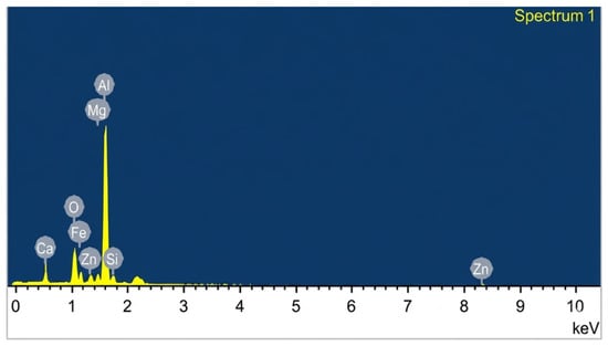
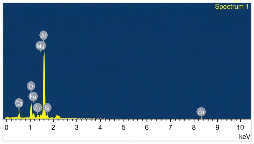
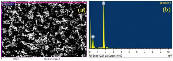
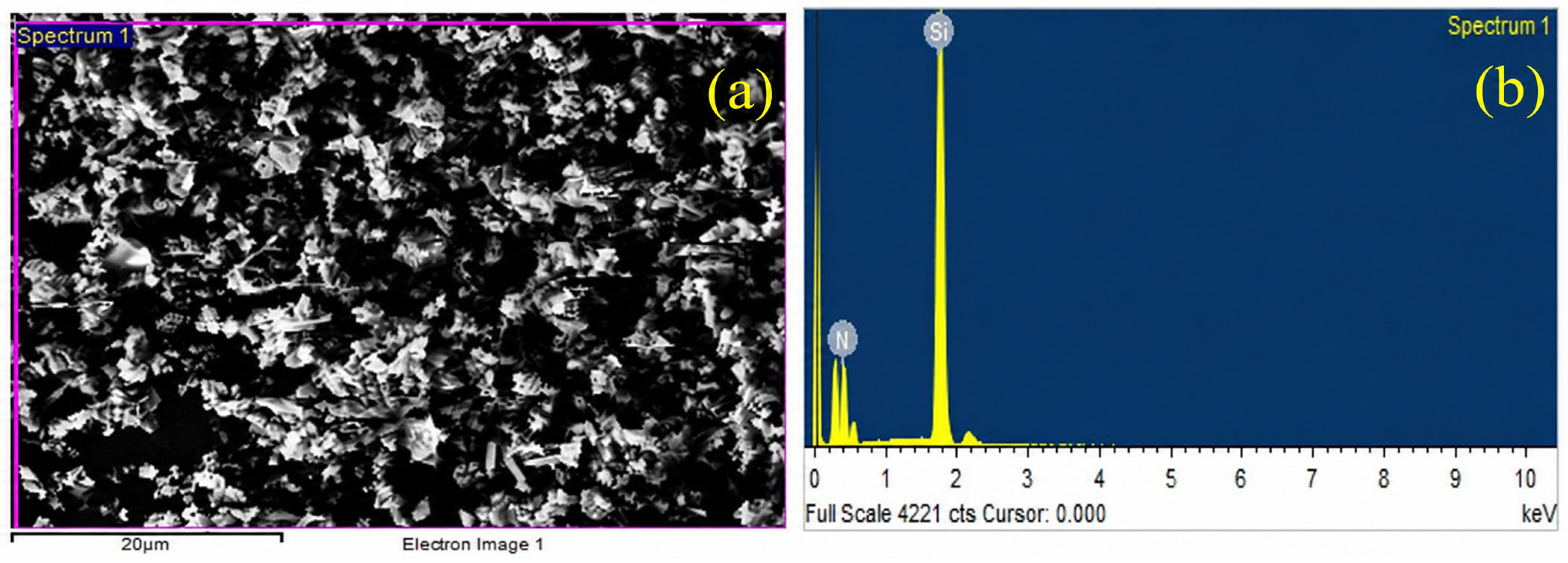
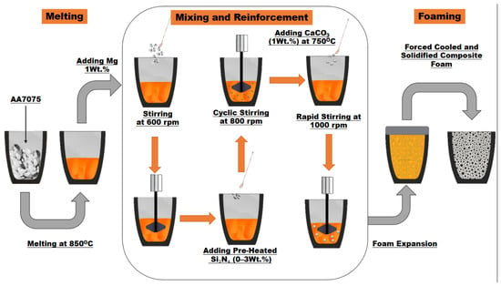
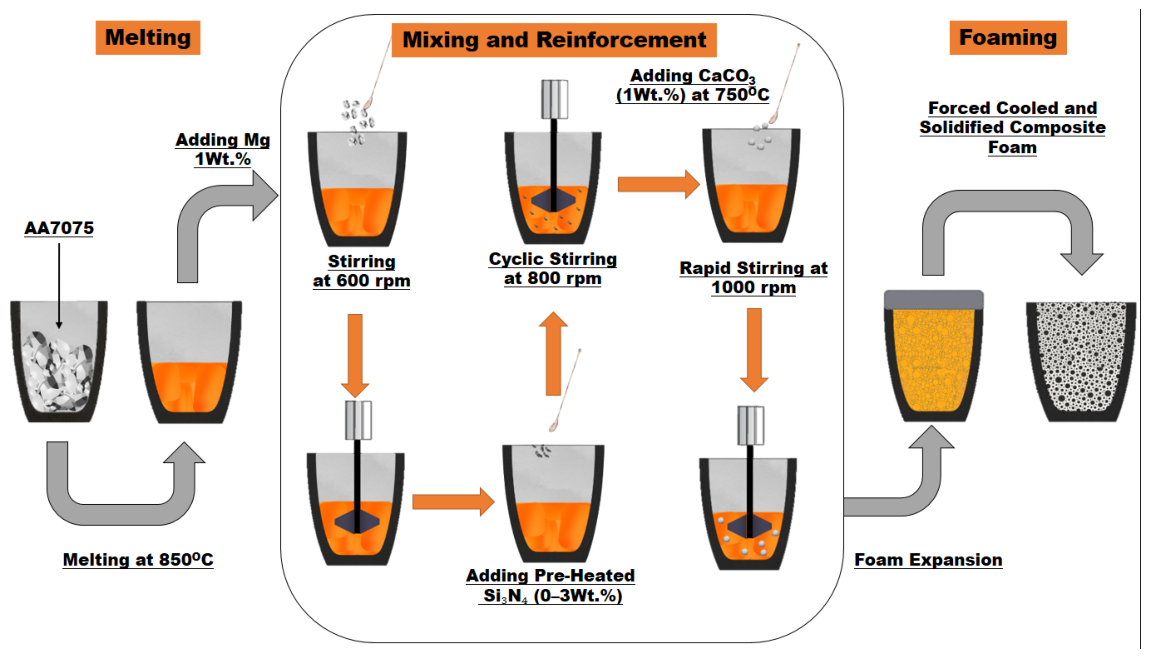
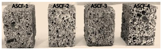
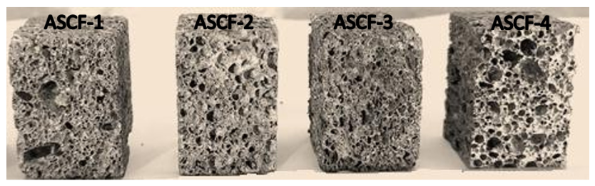
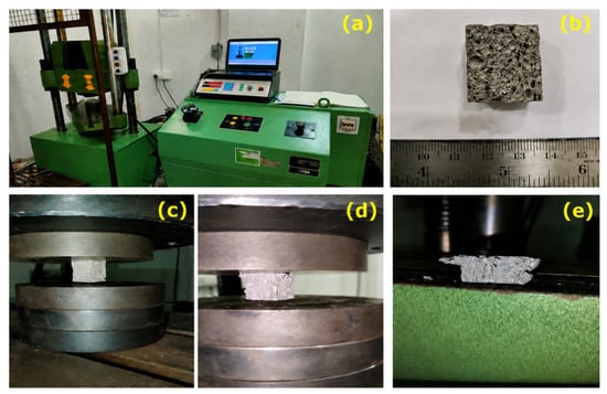
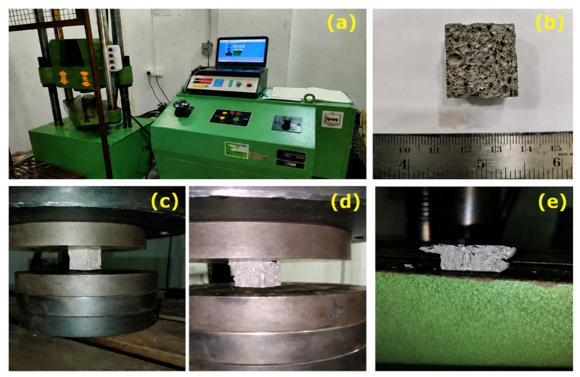
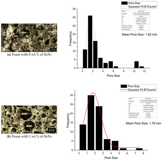
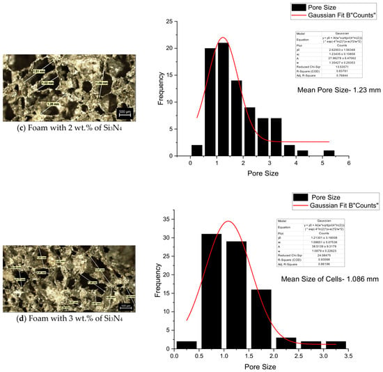
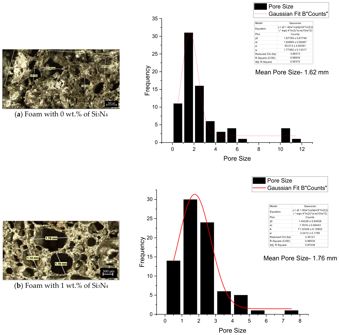
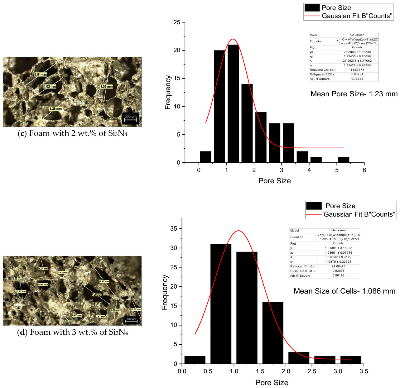
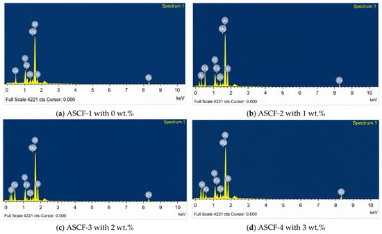
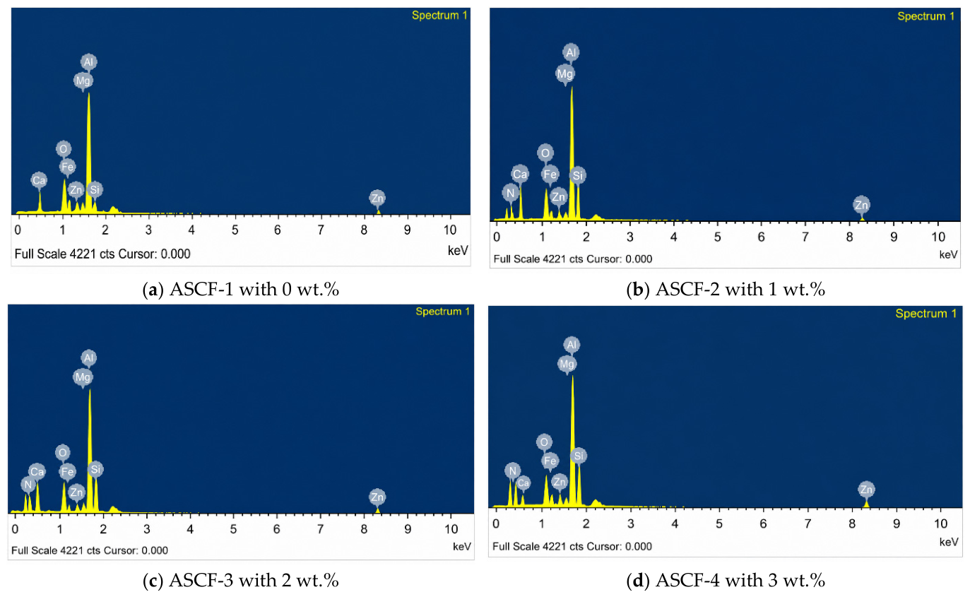
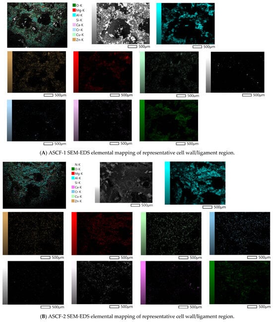
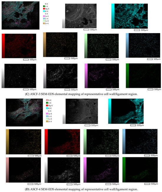
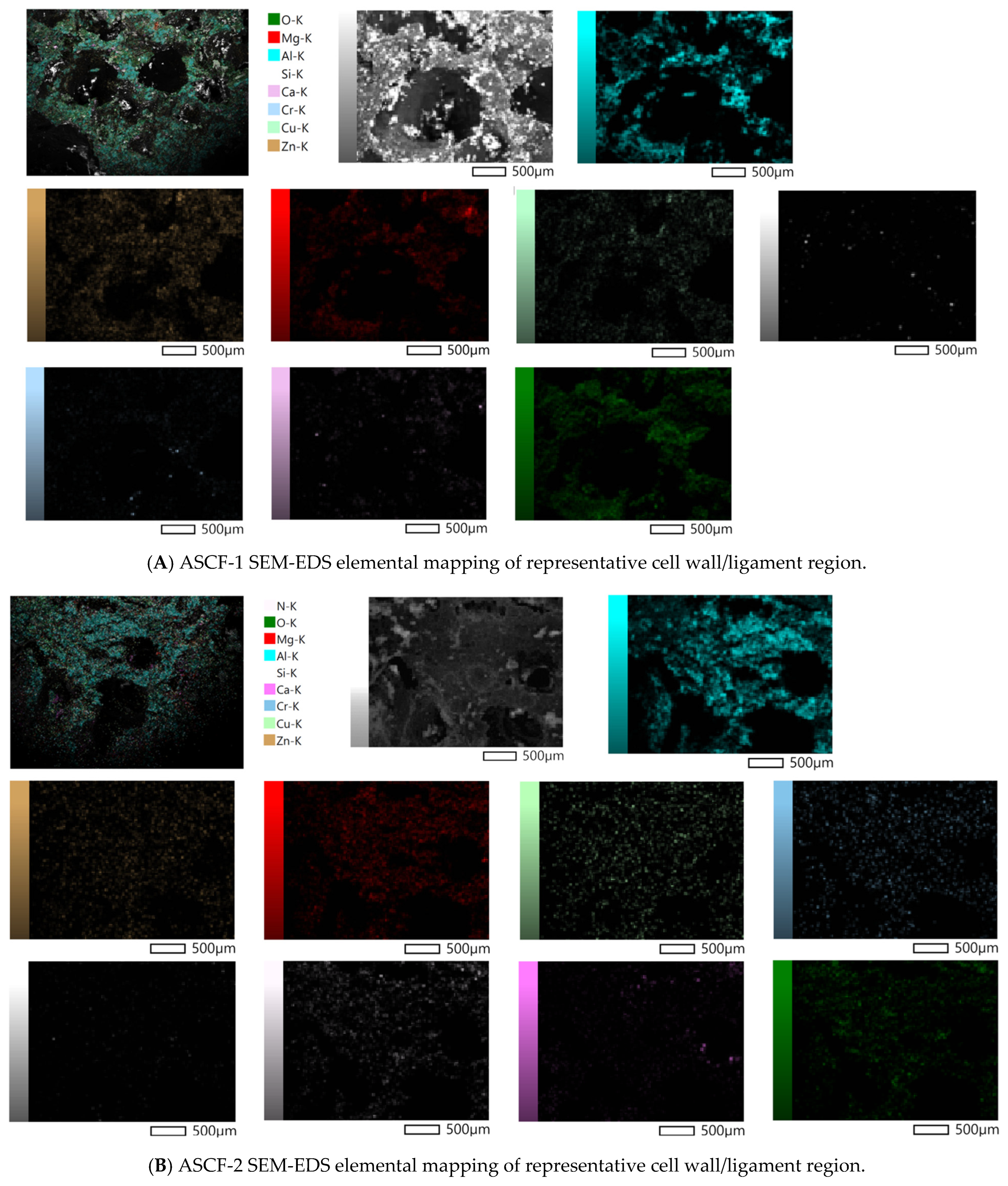
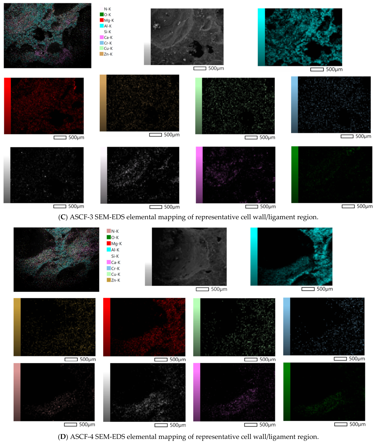
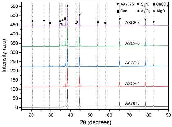
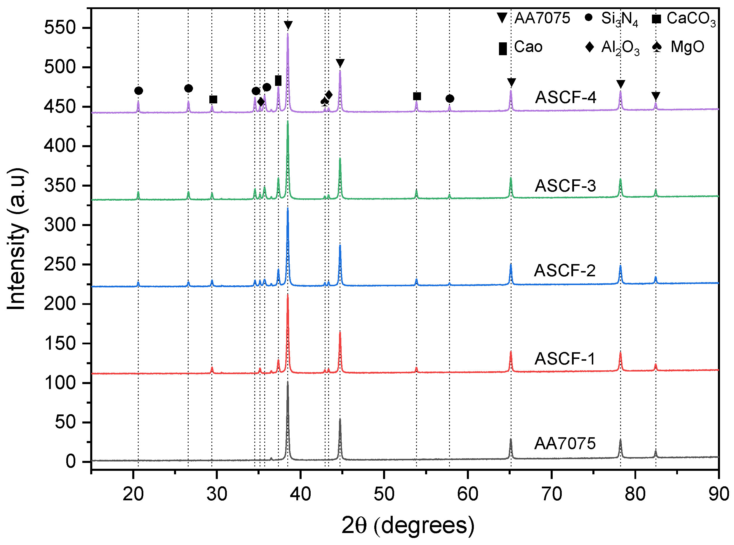
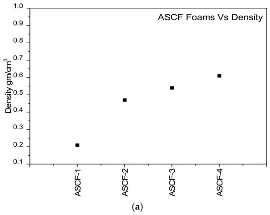
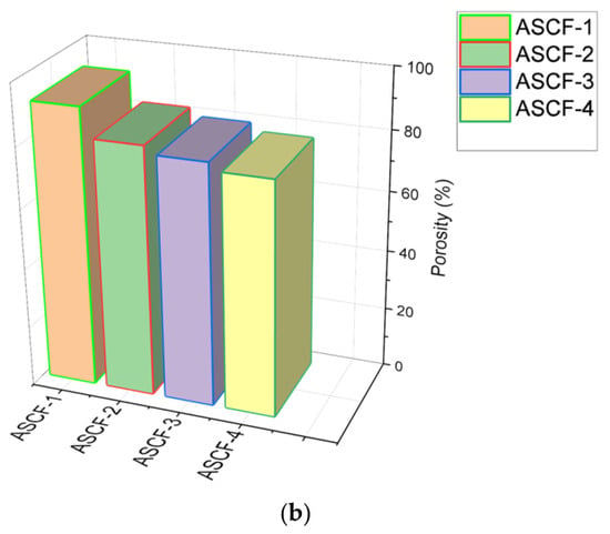
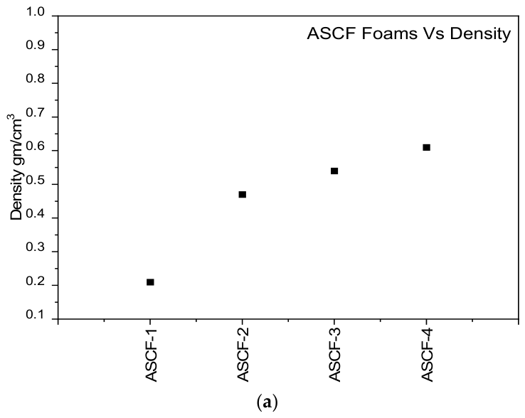
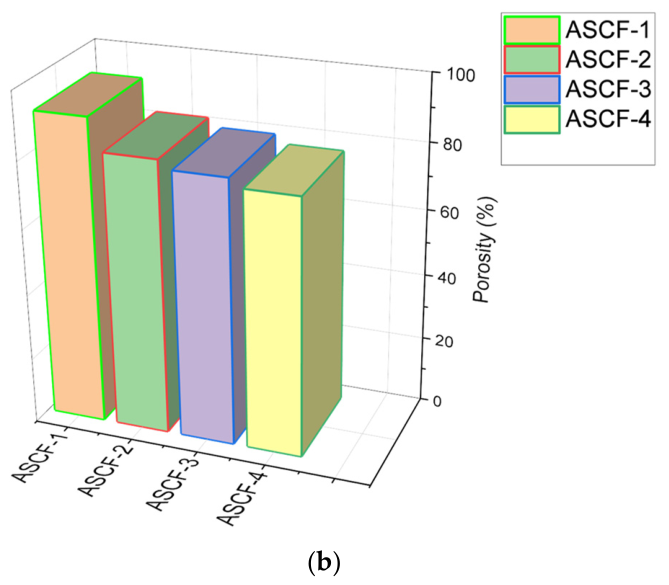
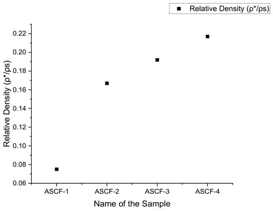
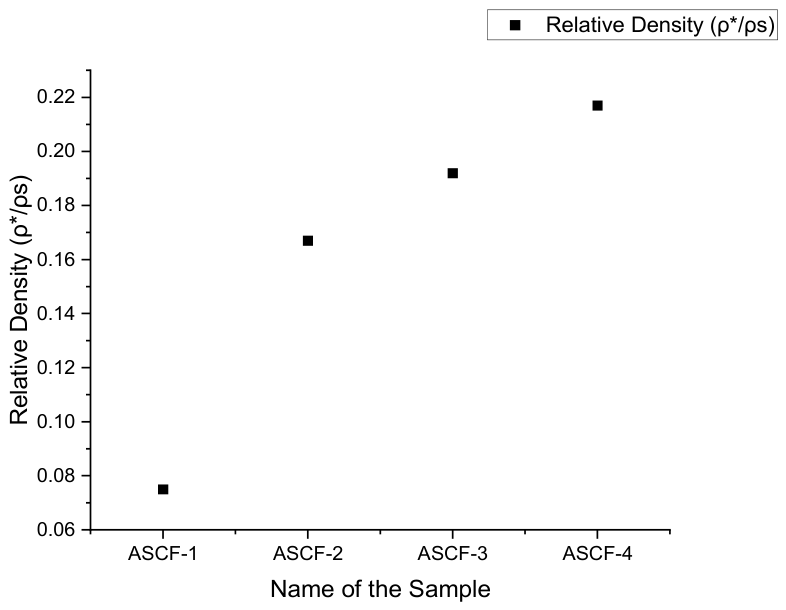
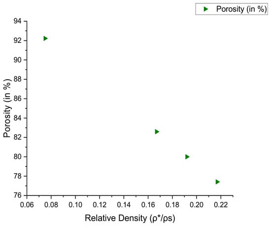
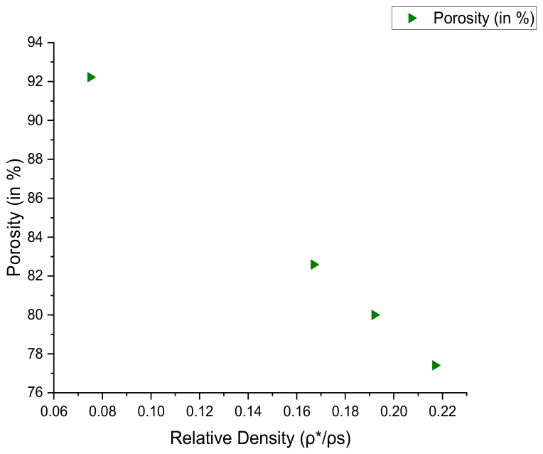
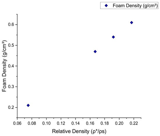
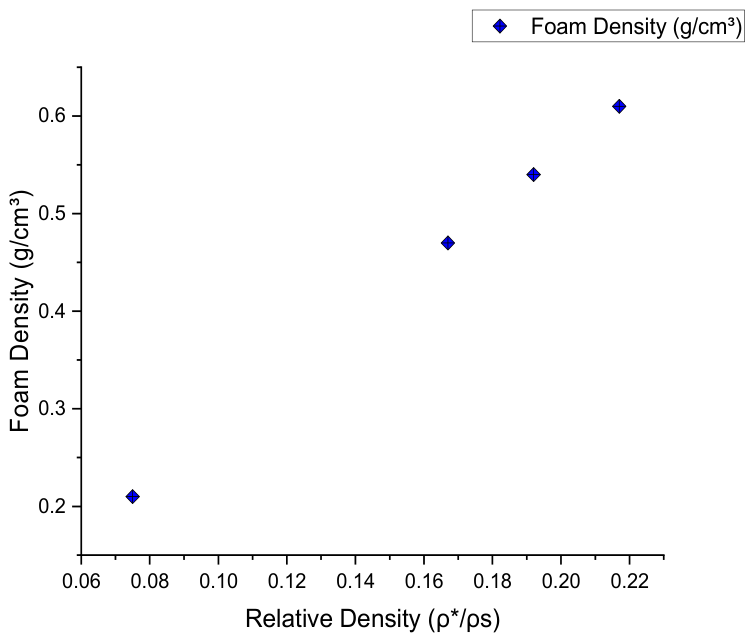
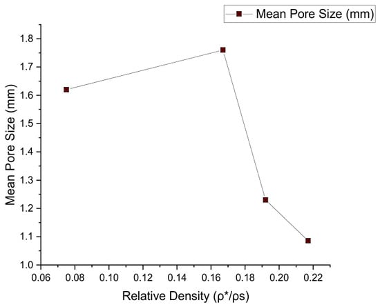
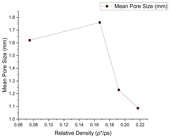
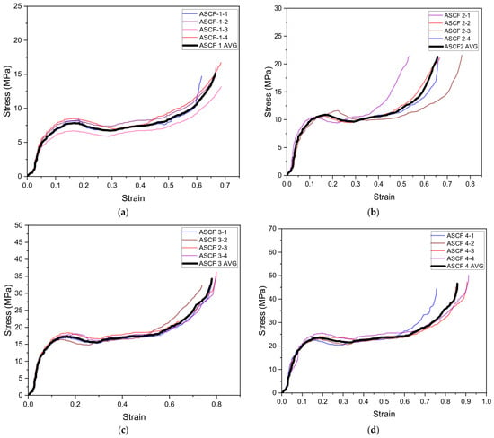
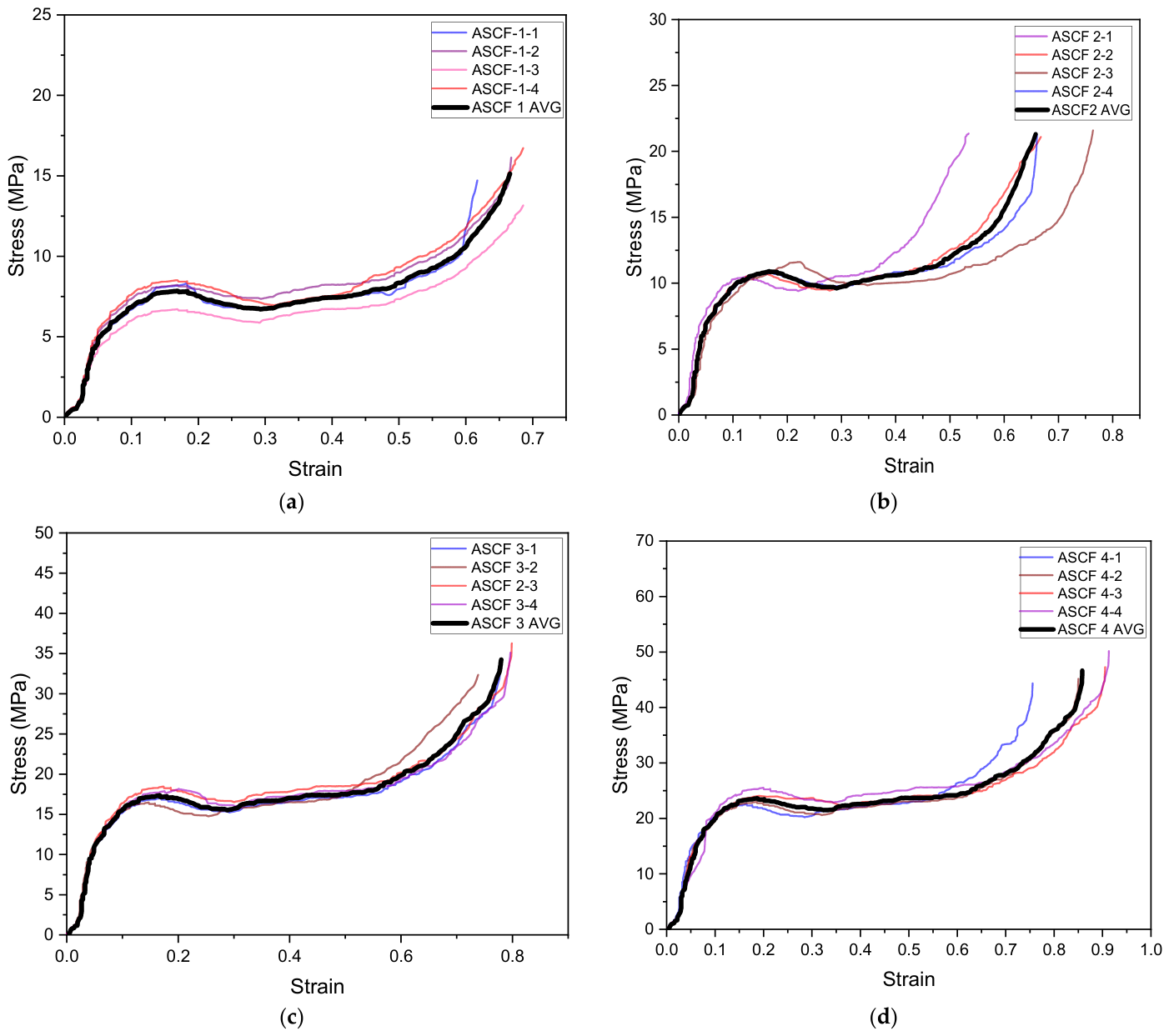
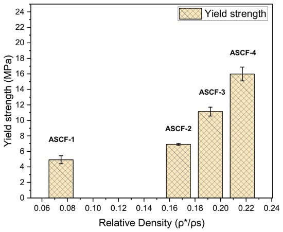
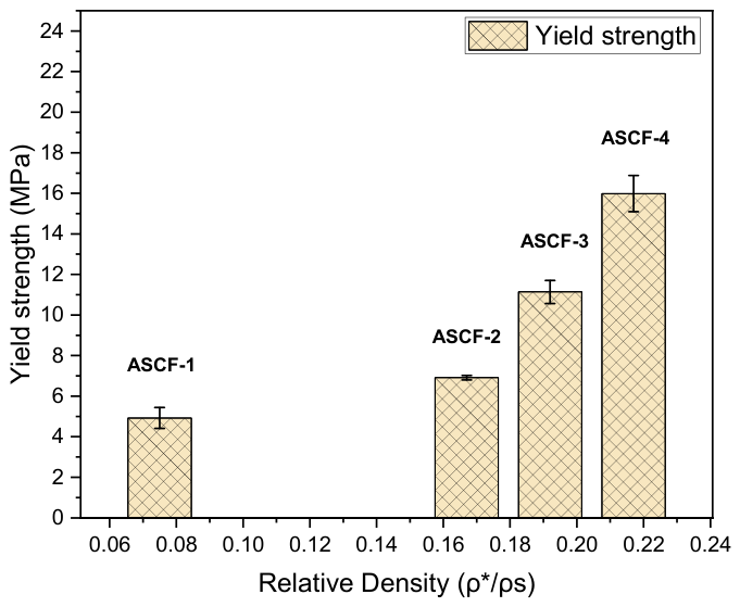
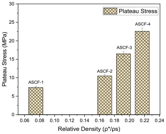
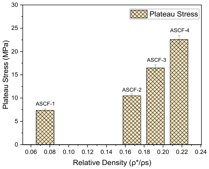
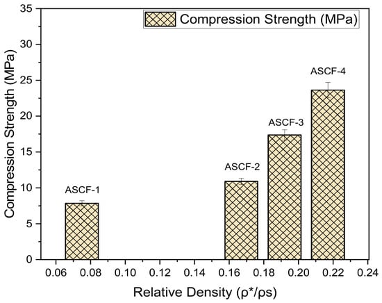
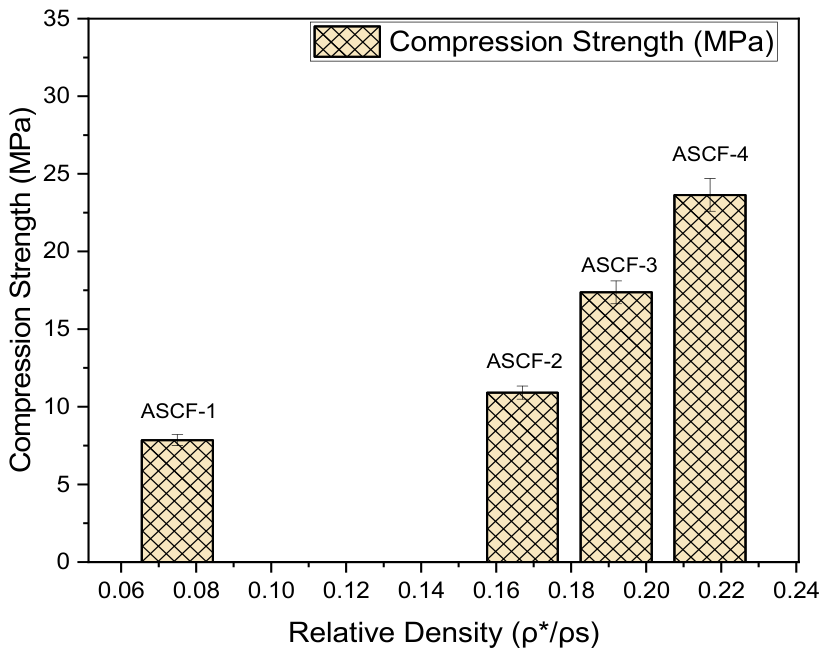
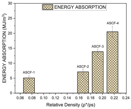
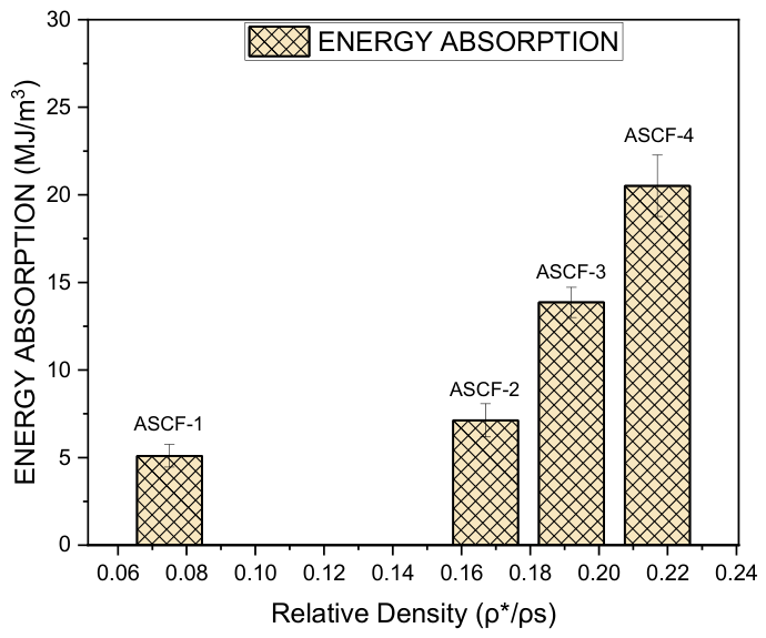
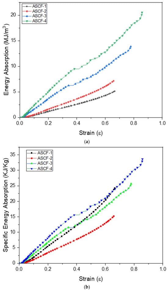
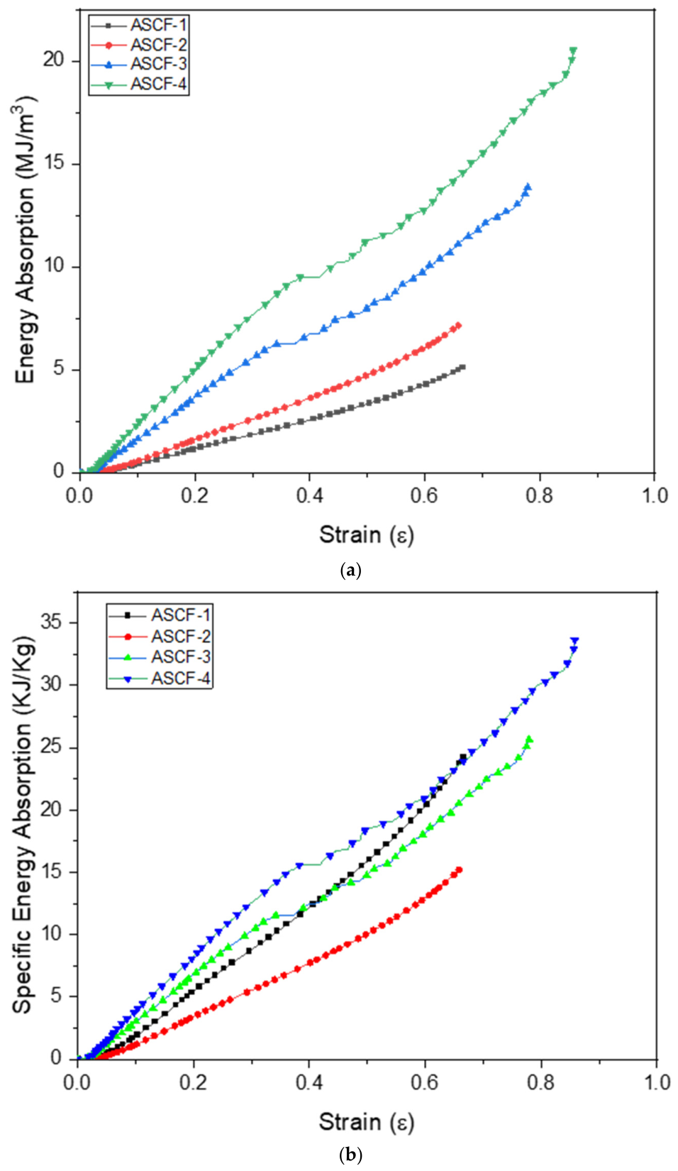
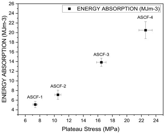
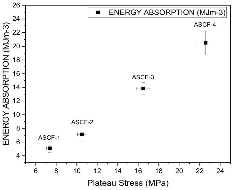
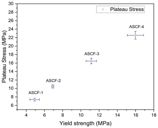
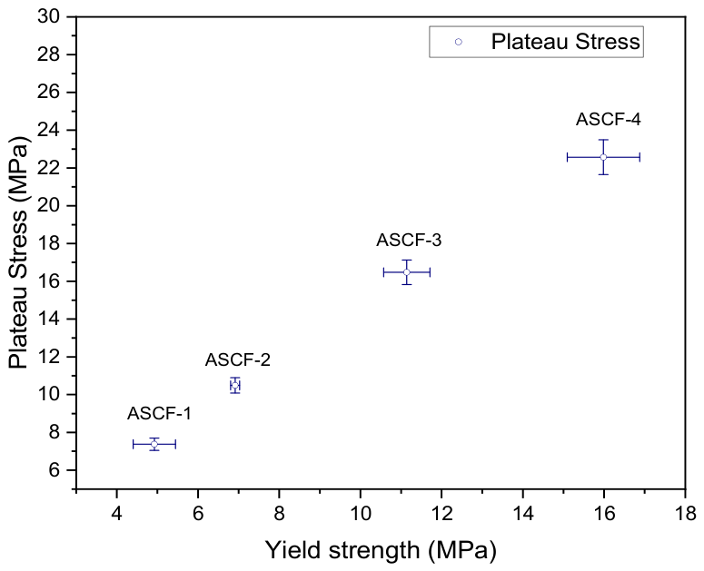
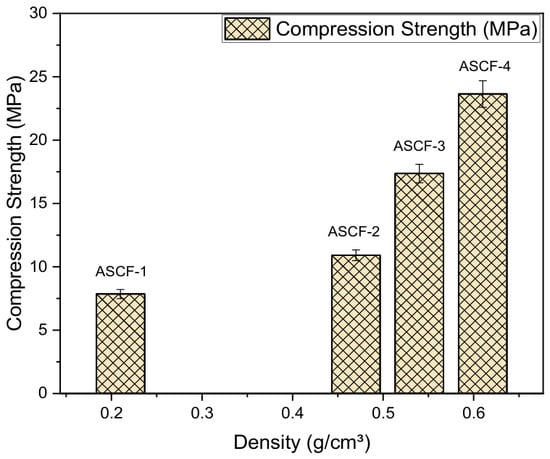
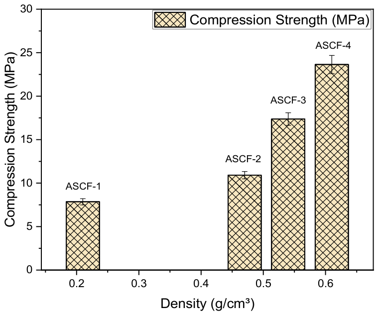
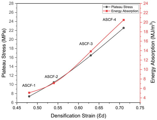
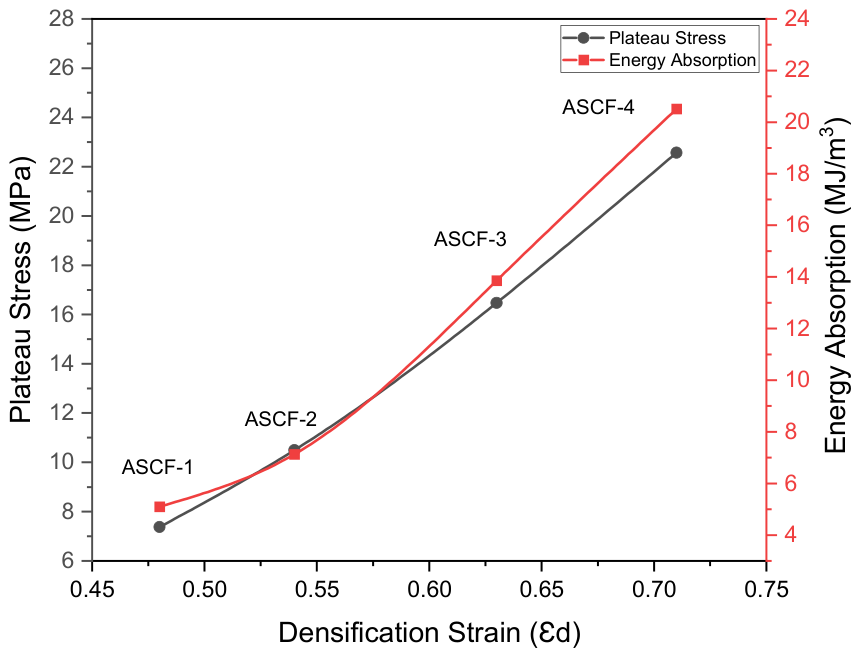

Disclaimer/Publisher’s Note: The statements, opinions and data contained in all publications are solely those of the individual author(s) and contributor(s) and not of MDPI and/or the editor(s). MDPI and/or the editor(s) disclaim responsibility for any injury to people or property resulting from any ideas, methods, instructions or products referred to in the content. |
© 2026 by the authors. Licensee MDPI, Basel, Switzerland. This article is an open access article distributed under the terms and conditions of the Creative Commons Attribution (CC BY) license.