


Abstract
The paper presents a critical review of the key work published to date on the hot ductility of steels in relation to the problem of cracking during continuous casting, including recent publications in the field. Laboratory testing methods that are most appropriate for evaluating cracking susceptibility are examined, with particular emphasis on the hot tensile test. The discussion covers both conventional carbon–manganese (C–Mn) and high-strength low-alloy (HSLA) steels, as well as the more complex advanced high-strength steels. Special attention is given to the influence of strain rate and the role of ferrite, both transformation-induced and deformation-induced, in controlling ductility. Increasing the strain rate invariably improves the ductility of steels containing a thin film of ferrite when it is present. This improvement is attributed to the work hardening of the ferrite, which promotes a more uniform distribution of strain, rather than localisation within the thin ferrite layer, thereby reducing the likelihood of fracture. The difficulties in increasing the strain rate in continuous casters are cited. Finally, based on insights from tensile testing, the paper considers practical approaches to preventing cracking in conventional curved-mould and vertical-mould arc continuous casting machines. Newly designed chamfered moulds have also recently been introduced, and these are claimed to reduce the incidence of corner cracking; their role is also discussed.
1. Introduction
The hot ductility of steels has been the subject of research for many years. A detailed review of cracking during continuous casting is not presented here, as the subject has already been extensively covered in the literature [1,2,3,4,5], including a comprehensive recent book devoted to the topic [6]. Instead, the present review concentrates on the use of the hot ductility tensile test to predict the safe temperature ranges that can be used to unbend (straighten) the strand without causing cracking during continuous casting.
The problem of cracking first attracted significant attention approximately fifty years ago, when continuous casting became the dominant method for producing steel slabs. At that time, certain high-strength low-alloy (HSLA) steels, particularly the peritectic C steels with Nb and high-N, V-containing grades, were found to be especially susceptible to cracking during the unbending stage of casting. Since then, considerable progress has been made in understanding the mechanisms responsible for cracking and in developing practical solutions. Nevertheless, cracking, particularly corner cracking, remains an issue in some microalloyed steels [7,8,9,10,11], as well as in transverse, edge, and corner cracking in the newer advanced high-strength steels such as TRIP (transformation-induced plasticity) and TWIP (twinning-induced plasticity) steels [12,13]. In the previous reviews, the importance of having coarser precipitation, particularly for TWIP- and TRIP-assisted steels, as well as using elements like B and Ce for refining the grain size [4] to improve ductility, has been discussed in detail. Similarly, previous reviews have shown that increasing the strain rate and reducing the cooling rate so that coarsening precipitation improves hot ductility and, hence, the ability to avoid cracking on unbending [1,2,3]. The present review basically concentrates on the use of the hot ductility test in helping to solve the problem of cracking, which still exists, particularly in the peritectic low-C steels, including TRIP-assisted steels and TWIP steels. This involves establishing an RA value which will avoid cracking and clarifying the role of ferrite in helping to avoid cracking in the peritectic C steels. The review also highlights how the research focus has changed with modern-day requirements; for example, advanced high-strength steels require better-quality steel, which later in the review is shown to lead to longitudinal cracking.
Although earlier research significantly advanced the understanding and solution of the problem, there has been renewed interest in cracking over the past decade. This arises because the use of vertical-mould arc casters [14] is increasing in the steel industry, as they produce higher-quality steels (“cleaner” steels) than curved-mould continuous casters. However, vertical-mould arc casters impose greater bending stresses than conventional casters, leading to a higher incidence of corner cracking [11]. As a result, the hot ductility behaviour of steels is still an important area of study. Much progress has recently been made in improving the design of the chamfered mould, one of which is claimed to eliminate corner cracking in peritectic C, HSLA steels, so that the focus of research may be changing from metallurgical studies to engineering design [15,16,17].
A schematic representation of a conventional bow-type curved-mould caster is shown in Figure 1a. In the continuous casting process, liquid steel is poured from the tundish into a curved, oscillating water-cooled copper mould, where it cools very rapidly (referred to as primary cooling), Figure 1a. On leaving the mould, the solidified shell is further cooled, more slowly than in the mould, by water sprays impinging on the solid surface, resulting in a reduction in strand temperature (secondary cooling). The strand is then guided by a series of rolls to the straightening unit. In this region, the secondary cooling rate, shown in Figure 1a, is considerably slower than that in the mould (the primary cooling stage).
Figure 1.
(a) Schematic diagram of the continuous casting operation showing the primary and secondary cooling stages. The mould is curved, with its curvature matching that of the strand, so that no bending is needed until the strand reaches the straightening unit. Adapted with permission from Ref. [2]. 2026, Taylor & Francis. (b) Schematic diagram of a vertical-mould arc continuous caster. Adapted from Ref. [4].
The oscillation of the mould causes ripples on the surface, and these oscillation marks are generally responsible for initiating cracking. Slab corners are particularly susceptible to crack formation because cooling is more rapid and thermal stresses are more severe in these regions [11]. The corner cracks in vertical-mould arc and curved-mould casters are very similar in many ways, but because of the difference in design, the vertical-mould caster is subject to greater strains during the straightening operation. This arises because, with the curved-mould caster, some bending of the strand already takes place in the mould. This means that, by comparison, in vertical-mould continuous casters, greater strain is required to take the strand from the vertical to the horizontal plane to achieve the same operation. However, the material properties required to avoid cracks are the same for both types, and this paper will concentrate on these properties rather than on the thermomechanical stresses acting on the skin of the strand, which are greater in vertical-mould arc casters than in curved-mould casters. The transition of the strand from the curved mould to the straightener is a gradual curve in a curved-mould continuous caster, Figure 1a, whereas in a vertical-mould arc continuous caster, Figure 1b, the changeover from below the mould to the straightener involves higher stresses and strains on the solidifying skin.
A schematic diagram showing the edge, corner, and transverse cracks that can occur during continuous casting with both types of moulds is shown in Figure 2.
Figure 2.
Schematic diagram showing the location of corner cracking. Crack initiation generally occurs in the mould at the base of the oscillation marks. The mould is adjustable in size to accommodate different slab widths. The fixed side is the side that remains stationary, and the loose side is the side that is adjustable to accommodate the different widths. The narrow side defines the thickness of the slab. Adapted with permission from Ref. [11]. 2026, Sage publications.
For the curved-mould caster, the cracks that are initiated in the mould propagate during the unbending operation. The cracks occur when there is some weakness at the austenite grain boundaries, and on unbending, the tensile stress at the surface pulls apart the grains. These cracks develop on unbending within the temperature range of approximately 700–900 °C, which corresponds to the range in which steels exhibit reduced ductility in the hot tensile test. This correlation underpins the use of the hot ductility tensile test as a tool for investigating cracking behaviour and for identifying the appropriate temperature ranges for carrying out the unbending operation in order to minimise crack formation.
A typical hot ductility curve showing reduction of area (RA) against temperature is shown in Figure 3 for a plain C–Mn steel of peritectic composition. The solid curve exhibits two regions of relatively high ductility at both the high- and low-temperature ends of the trough. Between these regions lies a trough of low ductility. This region of poor ductility coincides with the unbending temperature range, approximately 700–950 °C, where cracking on unbending is most likely to occur during continuous casting.
Figure 3.
Typical hot ductility curve with the Ar3 and Ae3 positions marked on the curve. (The Ae3 is the transformation temperature below which the austenite first starts to transform to ferrite on cooling under equilibrium conditions, and the Ar3 is that for non-equilibrium cooling conditions.) TIF is transformation-induced ferrite, DRX is dynamic recrystallisation, and DIF is deformation-induced ferrite. A with permission from Ref. [2]. 2026, Taylor & Francis.
Aim and Scope: This review concentrates specifically on the application of the laboratory hot ductility tensile test to identify safe, crack-free operational temperature windows for the unbending (straightening) stage of continuous steel casting. The scope encompasses classic C-Mn and HSLA grades alongside advanced high-strength steels (AHSS) such as TRIP and TWIP variants, focusing heavily on the structural and kinetic influences of strain rate, dynamic recrystallisation (DRX), and both transformation-induced (TIF) and deformation-induced (DIF) ferrite.
Novelty: Unlike historical reviews that prioritise bulk metallurgy or baseline precipitation data, this work highlights a modern paradigm shift driven by the industrial adoption of vertical-mould arc casters and advanced multi-tapered/chamfered engineering designs. Furthermore, it critically evaluates the emergence of physics-informed machine learning architectures as replacements for sparse empirical testing.
Limitations: This paper strictly evaluates fracture mechanics through the lens of microstructural evolution and grain-boundary vulnerabilities. It does not provide extensive mathematical thermomechanical stress modelling of the solidifying strand shell, nor does it establish an absolute, globally applicable statistical baseline for the reduction of area (RA) criterion needed to avoid cracking during the unbending operation that takes place on straightening.
2. Research Philosophy
A very important consideration in the design of a continuous caster is that the strand must be completely solid when the unbending operation takes place, Figure 1a,b. The skin must also be thick enough and strong enough to withstand any bending stresses incurred during the change in the direction of the strand from the vertical plane to the horizontal. Any burst or breakout on accomplishing this operation could be a disaster, with hot liquid steel spurting everywhere, involving loss of life and injury, as well as serious damage to the continuous caster. This meant that the design of the continuous caster had to be very strictly controlled, so that the cooling conditions and the stresses involved in transporting the steel from the mould to the straightener were such as to ensure that this did not happen. This generally limited the highest temperature at which the strand could be straightened and still be solid when unbending to approximately 1000 °C [2].
At the low-temperature end of the trough, there were also limitations on the straightening temperature, in that lower temperatures increased the power required to unbend the strand and increased the wear on the rolls, meaning that they had to be replaced more often. This limited the temperature range in which the unbending operation could be performed to 700–900 °C, the same temperature range in which the hot ductility trough for steels was located [1,3].
The research focus until the last 10–15 years was, therefore, centred on improving the hot ductility in the trough, so that it was sufficiently shallow to prevent cracking. A value of 40% RA, using standardised testing conditions in the hot ductility test, was considered to be adequate to achieve this [1,8]. This value was largely achieved by controlling the composition, strain rate, grain size, and cooling rate, as discussed in previous reviews [1,2,3]. The hot ductility test has been found to be an excellent quality control test in most steel companies. While many researchers have used a 40% RA threshold value to assess cracking sensitivity [1], a universally cross-industry statistical baseline has not been formally documented. The continuous casting operation is very complex, and even when standardised testing is carried out, industrially, there are other factors, such as small misalignment in the guide rolls, differences in cooling conditions, etc, which mean that each steel company has to establish its own acceptable RA value to avoid cracking, so that the hot ductility tensile test cannot be used with a universally acceptable fixed value for RA. Nevertheless, for testing in the research laboratory, provided that standardised conditions of testing are used, that is, the same strain rate, cooling conditions, solution treatment, etc., a fixed value can be used to decide the likelihood of cracking occurring. Industrially, the value for RA to avoid the risk of cracking on unbending is set by the company, depending on their own statistical analysis of cracking sensitivity and the standard of quality control required.
With the introduction of the newer advanced high-strength steels, the car industry required higher-quality steel, and the vertical-mould arc continuous caster became of more interest, so the focus of research changed. Although better-quality steel with a lower S level is produced by the vertical-mould continuous caster, it has the disadvantage that the bending stresses from the mould to the straightener have increased since more bending is required to accommodate the changeover from the vertical plane to the horizontal plane. This has led to an increase in the prevalence of corner cracking.
Decreasing the depth of the trough was now no longer a sufficient answer to the cracking problem. The research philosophy has, therefore, changed and now concentrates on encouraging all parts of the strand to be outside the 700–900 °C, a poor ductility temperature range when unbending, that is, to bend at the high- or low-temperature end of the trough, where ductility is very good. A large part of the review is devoted to this new scenario. However, with the more recent developments in continuous casting over the last five years, which include the use of chamfered moulds (particularly advanced chamfered/multi-tapered designs) and a redesign of the water-cooling system on the continuous casting route, the incidence of corner cracking can be reduced [15,16,17]. These changes ensure that the temperature of the slab corners is increased whilst not affecting the surface temperature, so that, on unbending, the temperature at the slab corners is always outside the poor ductility range on the hot ductility curve. This has been achieved by replacing the vertical mould with a tapered vertical mould, and this design is being continuously modified. Recently, an obtusely angled chamfered mould, shown in Figure 4, has been designed, which claims that it will not only reduce the incidence of cracking but also enable casting speeds of 1.8 m min−1, thereby increasing productivity.
Figure 4.
Schematic design of a new chamfered mould: (a) narrow face; (b) complete mould. The design is claimed to reduce corner cracking and allow high-speed steel casting to be achieved. (Generally, the speed of the strand is in the region of 1 m min−1 when casting thick slabs, whereas this mould claims that speeds of 1.8 m min−1 can be successfully achieved). Adapted from Ref. [15].
2.1. Influence of DIF (Deformation-Induced Ferrite) and Undeformed Ferrite on Hot Ductility Behaviour
At the solution temperature employed in the hot ductility test, the steel will be coarse-grained and fully austenitic. Since ferrite is softer than austenite [18], during the unbending operation, the plastic strain is preferentially taken up by ferrite.
The high ductility observed at the low-temperature end of the trough in Figure 3 is associated with the presence of a substantial amount of undeformed ferrite. As the temperature decreases and the γ/α transformation proceeds, the volume fraction of undeformed ferrite increases. Because ferrite possesses good intrinsic ductility, its presence improves overall ductility in this temperature range.
In coarse-grained steels, transformation on cooling from austenite always starts with a thin film of ferrite forming around the austenite grain boundaries. With further cooling, more ferrite forms and gradually consumes the austenite grains. In contrast, during deformation, this transformation to a thin film of ferrite at the boundaries takes place much more rapidly, as deformation increases the number of defects, thereby enhancing diffusion [19]. At the low strain rates characteristic of both thick- and thin-slab casting, once deformation-induced ferrite forms, it hardly grows any further. The thin film promotes strain localisation and leads to premature ductile fracture, thereby increasing the risk of cracking during continuous casting; Figure 5.
Figure 5.
Typical figure showing a deformation-induced ferrite film (white) at the prior austenite grain boundaries and the associated intergranular cracking for a high-Al steel of peritectic composition, tensile-tested at 800 °C after cooling from 1300 °C. Adapted with permission from Ref. [2]. 2026, Taylor & Francis.
It has been shown [19] that this film of deformation-induced ferrite (DIF), Figure 5, can form very easily with very little strain (<3%), meaning that it can develop even during the unbending operation. Because the ferrite film is significantly softer than the surrounding austenite, the imposed strain of approximately 3% is almost entirely concentrated within this narrow region, resulting in early ductile failure. Furthermore, DIF can form well above the Ar3, approaching the Ae3. As a consequence, the trough associated with this ferrite film commonly covers the whole temperature range from the Ar3 to the Ae3, often exceeding 100 °C. (The Ae3 is the transformation temperature below which the austenite first starts to transform to ferrite on cooling under equilibrium conditions, and the Ar3 is that for non-equilibrium cooling conditions.)
To estimate the temperature range over which poor ductility occurs, i.e., the width of the trough, both the Ae3 and Ar3 can be reliably calculated using thermodynamic models and regression equations [20]. Hence, the width of the trough for many steels can be approximately established; Figure 3.
Although the core process of the formation of DIF is known, there is still missing information. As far as continuous casting is concerned, the main work on understanding DIF in coarse-grained steels was carried out in the 1980s, and there has been little since. Since then, most of the work has been devoted to using DIF to form ultrafine-grained steels [21].
The following figure of %RA against the volume fraction of ferrite, Figure 6, goes a long way towards explaining the role of DIF in controlling hot ductility during unbending [22,23]. In this study, Cardoso et al. [23] tensile-tested four low-C (0.08%) steels: two plain C–Mn steels and two HSLA steels. The specimens were solution treated at 1350 °C to produce a coarse-grained, fully austenitic structure. They were then tested to failure over the temperature range of 700–1000 °C at a strain rate of 1 × 10⁻³ s−1. Figure 6 presents the variation in %RA at fracture as a function of the ferrite volume fraction for one of the steels.
Figure 6.
The influence of ferrite volume fraction on %RA values in an austenite/ferrite matrix [22]. The solid curve is that expected from undeformed transformation-induced ferrite (TIF), and the curve for DIF is the dashed curve, but note that there are no points between about 5% volume fraction and 45% volume fraction of ferrite. Adapted from Ref. [23].
The trends shown in Figure 6 are similar for the four steels tested, irrespective of composition. In each case, the %RA value was plotted against the volume fraction of ferrite present at the point of fracture. The applied strain rate of 10−3 s−1 used corresponds to that experienced during the unbending operation for thick-slab casting (approximately 200 mm in thickness).
At the beginning of the curve, where the ferrite volume fraction is below 3% (the first 6 points, ringed in Figure 6), transformation occurs with a very thin ferrite film forming along the prior austenite grain boundaries. Under these testing conditions, this ferrite is classified as DIF since it forms much more rapidly than ferrite produced solely by thermal transformation. When this thin grain-boundary ferrite film is present, ductility is consistently poor, with %RA values in the range of 10–15% (Figure 6). Fracture in this region is intergranular, as the strain is concentrated within the softer ferrite film, located at the austenite grain boundaries, Figure 5.
A notable feature of Figure 6 is the absence of data points between this low-ductility intergranular region and the region where %RA exceeds 40%, a value generally considered necessary to avoid cracking using standardised testing conditions [1]. The fractures are now transgranular.
The absence of intermediate data points implies that a critical ferrite volume fraction must be reached before strain can be redistributed more uniformly between ferrite and austenite. While the DIF exists only as a thin grain-boundary film, strain remains localised in the ferrite film, and ductility remains poor. Further transformation of austenite to DIF is effectively suppressed until the strain can be distributed more evenly. Only when a sufficient volume of ferrite is present, approaching about 45%, as indicated in Figure 6, does the deformation become more uniformly distributed, allowing ductility to improve and reducing the likelihood of cracking.
The conclusion reached by Cardosa and Yue [22,23] was subsequently confirmed by Stewart, Jonas and Mintz [19], who established the dynamic TTT (Time, Temperature, Transformation) diagrams for the formation of DIF in fine- and-coarse-grained austenite.
On deformation, the recovery of ferrite at the high temperature of testing used in the hot tensile test is very rapid, as ferrite has a high stacking fault energy (SFE). Therefore, the ferrite remains soft, even with deformation [19,24], and the strain is localised in the thin film, leading to low overall ductility.
Thus, although DIF is intrinsically soft and ductile, similar to the normal undeformed transformation-induced ferrite (TIF), because it forms first and recovers so easily and because the strain is only taken up by the thin film of ferrite, it never develops further into the austenite matrix before premature ductile fracture occurs. When sufficient time is given for the normal TIF to develop, ductility can improve again, but only then. Because of the high rate of recovery of ferrite, the solid curve in Figure 6 is that expected for unstrained ferrite (TIF), whereas the dashed curve is that expected for deformation-induced ferrite (DIF).
This very early work [22,23] was not fully appreciated at the time, and even now, its consequences are not realised. There has been, for many years, a demand by the steel industry from research institutions for a critical value for the %RA value, above which cracking would not occur for the peritectic steels. Two very different answers were given. Nippon Steel Corporation, on the basis of its research work, quoted 60% [25,26]. Mintz et al. [1], on the basis of their research work, used 40%RA as the criterion. Such a wide difference shows how important it is to standardise the testing conditions. The higher value applies when casting the tensile specimens, and the lower value when solution treating is the testing procedure. The cause of this wide difference is related to the austenite grain size, with this being coarser when the tensile specimen is cast. Cardosa and Yue’s past research work [22,23] gives the reason for the big difference. Their work shows that it is not the value of the %RA which is what is controlling ductility but the amount of TIF that is present and when the changeover from intergranular to transgranular failure occurs. The value of 45% TIF as the criterion to avoid cracking is much more meaningful than a 40%RA requirement. There is, for an unbending thick slab, a race between the time taken for localised failure to occur in the thin film of DIF and the time taken for sufficient TIF to form to prevent this localisation. If the time is too short, low-ductility intergranular failure occurs in the DIF thin film. If the time is sufficiently long to allow 45% TIF to form, this strain localisation is avoided. In the nucleation process, finer austenite grain sizes with their greater grain surface area provide more nucleation sites for transformation to ferrite and so can reach the necessary volume fraction more quickly.
The coarser the austenite grain size, the more time is needed to form the critical amount of TIF and hence a greater amount of strain, viz., more RA is needed to achieve the critical amount of TIF. Hence, the coarser as-cast austenite requires 60%RA to achieve this, and the finer austenite grain size produced after solution treating requires only 40%RA to meet the requirement. Slower cooling rates [25], in addition to coarsening precipitates, will also give more time for TIF to form without localised failure occurring.
At the other end of the trough (on the opposite side of the curve to the ferrite-formation region), the good ductility is due to dynamic recrystallisation (DRX), which for HSLA steels does not generally take place on straightening thick and thin slabs until the temperature is above 900 °C [19,25]. This is due to the very small strain involved when unbending takes place (<3%), combined with a very coarse austenite grain size. Nevertheless, although unrecrystallised austenite has relatively low ductility compared to that of a fully ferritic steel, it is still better than when the thin film of deformation-induced ferrite (DIF) is present, and this (generally amounting to about a 10% improvement in the RA value) is often enough to avoid cracking (the dashed curve in Figure 3 represents that for unrecrystallised austenite).
Thus, to avoid cracking, straightening can take place either at the high- or low-temperature ends of the trough. The temperature in Figure 3 at which dynamically recrystallised austenite changes to unrecrystallised austenite often corresponds to the temperature at which DIF first forms, as the presence of DIF prevents the recrystallisation of the austenite [19]. At the high-temperature end, the temperature is generally high enough for the strain in the tensile test (in the region of 30%) to cause dynamic recrystallisation (DRX) and excellent ductility. However, for bending at the high-temperature end, corner cracks can arise because, although the majority of the slab surface when unbending may be at a high enough temperature to avoid cracking, the corner temperature is much lower and falls into the temperature range of 700–900 °C, where cracking can occur. Bending temperatures above 1000 °C are often needed to raise the corner temperature sufficiently before good ductility can be achieved, and such a high temperature is not usually achievable with continuous casters [19,27].
As was already mentioned, the width and position of the trough can generally be approximately obtained from a knowledge of the Ae3 and Ar3 temperatures. This relationship between the width of the trough and the temperature range between the Ae3 and Ar3 has been found to apply to the large number of hot ductility curves accumulated from earlier work [1,2,3], in which the hot tensile test was carried out with one cooling rate to the test temperature of 60 °C min−1. This makes the hot tensile test using one cooling rate so useful, as it clearly separates the regions where normal TIF forms from the region where DIF forms, Figure 3. It also separates the region of unrecrystallised austenite from the region where dynamically recrystallised austenite first forms, so that the appropriate temperature ranges for unbending without cracking can be chosen; Figure 3.
Thus, in Figure 3, for good ductility, at the low-temperature end of the trough, unbending has to be carried out when at least 45% undeformed ferrite is present, which normally occurs approximately 30 °C below the Ar3 for undeformed transformation. At the high-temperature end of the trough, unbending needs to be carried out, if possible, above 1000 °C, to ensure that corner cracking does not occur.
2.2. Causes of Cracking
In addition to mechanical reasons for cracking, such as misalignment of the guide rolls and incorrect operation of the mould oscillator, the main metallurgical factors influencing the hot ductility and hence susceptibility to cracking are the composition, cooling conditions, dynamic precipitation, grain size, and the strain rate used during the bending operation [1,2,3]. The cracks are formed along the prior austenite grain boundaries (Figure 5) and occur when there is present on cooling either (a) this thin film of the softer DIF phase surrounding the austenite grains (Figure 5) and/or (b) fine dynamically formed precipitates, which increase the strength of the matrix and, therefore, promote grain-boundary sliding (GBS) [3] by increasing the shear stress acting on the grain boundaries.
The finer the precipitation, the worse the ductility. GBS is also important in controlling the hot ductility of these steels because at the low strain rates pertaining to thick- and thin-slab casting (200 mm-thick and 50 mm-thick slabs, respectively), creep conditions apply [28]. The precipitates formed in the trough often give rise to precipitate-free zones (PFZs) which behave in a similar ductile manner to the soft ferrite films. For the low-C, HSLA steels, the inclusions and precipitates at the boundary cause, on straining the steel, void formation, leading to crack growth and propagation. For a given volume fraction of precipitation at the austenite grain boundaries, finer precipitation also makes it easier for cracks to link up along the boundaries [1,2,3].
2.3. Influence of Strain Rate on the Hot Ductility Curve of Low-C Steels
Previous reviews [1,2,3] have concentrated on the benefits to hot ductility of adjusting the composition, refining the austenite grain size, and coarsening the precipitates, but the present shorter review focuses more on the strain rate, as this is an integral part of the hot tensile testing technique.
A simple way to explain the hot ductility of low-C steels is that the good ductility at the low-temperature end is due to the presence of at least 45% normal transformation-induced ferrite. The strain taken by the tensile specimen is then no longer concentrated solely in the ferrite film. The good ductility at the high-temperature end is due to dynamic recrystallisation, or at least to the presence of a fully unrecrystallised austenitic structure.
The factors that influence the hot ductility of these steels can be understood more readily by studying Figure 7. In this figure, the shape, depth, and extent of the trough itself can be explained by two different curves: one for the critical strain for dynamic recrystallisation against temperature, εc, and one for the fracture strain, εf, which can be taken as the %RA value at fracture. This value is assumed not to change, and the base of the trough is given in Figure 7a as a “horizontal” straight line. Where the two curves meet, Td, is the temperature above which dynamic recrystallisation is possible, Figure 7b. The effect of strain rate, grain size, and precipitation can then be interpreted using Figure 7b, Figure 7c and Figure 7d, respectively.
Figure 7.
Schematic diagram showing (a) how the width of the ductility trough at the high temperature side of the trough could be controlled by where the curve for εc1, the critical strain for DRX, intersects the curve for the fracture strain, εf1, this being at T(D1), the temperature for DRX; (b) how increasing the strain rate reduces the depth and width of this trough where εc1, εf1, and T(D1) refer to the lower strain rate and εc2, εf2, and T(D2) refer to the higher strain rate; (c) how refining the grain size reduces the depth and width of the trough, where εc1, εf1, and T(D1) refer to the coarser grain size and εc2, εf2, and T(D2) refer to the finer grain size; and (d) how precipitation causes the width and depth to increase where εc1, εf1, and T(D1) refer to there being no precipitation and εc2, εf2, and T(D2) refer to when precipitation is present. Adapted with permission from Refs. [1,3]. 2026, Taylor & Francis.
The composition and cooling rate are also important in controlling ductility because they control the Ae3 and Ar3 temperatures. In addition, the segregation of elements to the austenite grain boundaries can be a critical factor, since the segregating element can often weaken or strengthen the grain boundaries [29]. The cooling rate also controls the size of the precipitates as well as influencing the transformation temperatures.
Increasing the strain rate, as can be seen from Figure 8, where a plain C–Mn steel has been tested at three strain rates of increasing magnitude, is a good method of improving the hot ductility in these steels. Increasing the strain rate causes the thin film of ferrite to work harden, so its strength increases, approaching that of the austenite. This eventually allows more of the strain to be taken by the austenite and less by the thin film of ferrite, so that the ferrite volume fraction can increase to the critical value of more than 45% by volume. There is then no need to have any TIF present before unbending, as is necessary at lower strain rates.
Figure 8.
Influence of strain rate on a 0.4%C plain C–Mn steel, illustrating that ductility improves as the strain rate increases. The low strain rate of 10−4 s−1 makes it possible to show the various stages the structure goes through in the tensile test, i.e., the presence of the thin film between the Ar3 and Ae3, the presence of unrecrystallised austenite which gives only a small improvement in hot ductility, and the final stage when there is a large improvement in ductility when the austenite has dynamically recrystallised. Adapted with permission from Ref. [2]. 2026,Taylor & Francis.
The increase in the fracture strain, Figure 7b, also causes the temperature at which DRX takes place to be lowered, thus narrowing the trough at the high-temperature end of the curve, Figure 7a,b. Furthermore, higher strain rates reduce the amount of GBS in the austenite so that the cracks along the boundaries have less time to grow, thus improving the ductility of the unrecrystallised austenite. The reduced time available for the voids associated with the MnS inclusions and precipitates at the austenite grain boundaries to grow also improves ductility [19].
Increasing the strain rate, therefore, by preventing the thin film of ferrite from taking all the strain and leading to premature fracture, results in a higher fracture strength and consequently reduces the depth of the trough; Figure 7b.
In addition, the additional defects produced by deformation increase the diffusion rate for the transformation, so the Ar3 is raised, narrowing the trough at the low-temperature end of the curve and resulting in a much narrower trough; Figure 7b and Figure 8.
Unfortunately, there is little one can do to increase the strain rate in continuous casting, as the strain rate is mainly dependent on the diameter of the rolls used during straightening and the thickness of the slab being continuously cast, and these are fixed.
Because of the seriousness of this cracking problem when it arises, laboratory tests are required to simulate the bending operation so that industry can establish the optimum conditions to avoid cracking. Many such tests have been developed to simulate the bending operation, from the very simple hot tensile ductility test outlined above to more expensive bend tests which can be stopped at the small strains used in the bending operation [9,30], compression testing [9,30,31,32], and ideally even the use of an actual laboratory mini-continuous casting plant [33]. Compression tests have an advantage over tensile tests because they are more accurate, as they are not subject to “necking”. However, the simple hot ductility tensile test is still adequate to clearly show the safe temperature regions for avoiding cracking.
The hot ductility tensile equipment has also been developed further to allow the casting of the tensile specimens directly, followed by straining the specimens to failure. In addition, the cooling conditions are often modified to be closer to those of continuous casting, incorporating primary and secondary cooling rates instead of using a single cooling rate [9,13,34,35,36,37,38,39,40].
2.4. Laboratory Introduction of a Step in the Cooling of the Strand to Make Conditions More Compatible with the Continuous Casting Process
The most popular hot ductility test, which is still carried out [7,8,41,42,43,44,45], is to simulate the continuous casting operation in the simplest possible way. The tensile specimen is first heated to a high temperature, usually 1250–1350 °C. This results in dissolving most of the microalloying precipitates back into solution and produces an austenite grain size reminiscent of the as-cast grain size (200 to 300 µm compared to 500–1000 µm for the continuous cast grain size). The specimen is then held for a few minutes to stabilise the temperature and then cooled at the average cooling rate that the strand undergoes from the mould to the straightener. This was calculated to be about 60 °C min−1 for thick (220 mm), wide slab casting and 200 °C min−1 for thin (50 mm), wide slab casting.
The tensile specimen is then strained at the strain rate experienced at the straightener (10−3 s−1 for thick and 10−2 s−1 for thin slabs). Obviously, these are very rough simulations of the commercial operation; for example, the cooling conditions during the continuous casting operation can be seen from Figure 9 to be very complex, and the strains in the tensile test (around 30%) are very much higher than in the bending operation (3%), allowing DRX to occur much more easily.
Figure 9.
A 2–3-dimensional computerised strand temperature model for predicting thermal history during continuous casting of a 240 mm-thick strand cast at 1 mm min−1. The four curves are for different positions on the slab from the corner (the lowest temperature curve in the figure) to the mid-width centre (the highest temperature curve in the figure). Note the very high temperatures, close to the melting point at the centre of the slab when unbending (top curve), and the unbending temperature at the corner is approximately 850 °C, when cracking can occur. Adapted with permission from Ref. [46]. 2026, Taylor & Francis.
Nevertheless, these rather simplistic attempts to simulate the continuous casting operation were found to give meaningful results and were of great benefit in reducing cracking in the continuous casting of plain C–Mn steels and the simpler HSLA steels containing microalloying additions of V and Nb. For the Ti-containing steels, in order to take the Ti precipitates back into solution, the tensile specimens had to be cast in situ. It was found that, on testing, whereas Ti microalloying additions were beneficial in preventing cracking when the steel was continuously cast, the opposite behaviour occurred in the laboratory test. Adding Ti always resulted in worse ductility [46]. A slightly closer agreement was found when an undercooling step was introduced using the same cooling rate for the primary and secondary stages [40], but the addition of Ti still always resulted in worse ductility.
Only when conditions were made even closer to the cooling conditions used in the continuous casting process, by introducing both a fast primary and a slow secondary cooling rate, was this discrepancy finally resolved [46]. In the continuous casting process, Figure 10a,b, for thick-slab casting, the first stage in the cooling process is very rapid (600 °C min−1) and the secondary cooling rate is much slower (15 °C min−1), and slower than the one average cooling rate used previously in the hot ductility tests (60 °C min−1) [46]. Only when the two stages were introduced into the hot tensile test was the benefit of adding Ti to steels to prevent cracking revealed. However, although this solved the disparity between the industrial and laboratory results, the reason for the difference in behaviour was not clear and still requires further investigation.
Figure 10.
(a) Schematic diagram of the cooling cycle in the hot tensile test, showing the fast primary cooling until reaching Tmin, followed by a subsequent rise in temperature to Tmax (the step), followed by the slow secondary cooling until unbending, where Tu is the temperature at which the strand is unbent. Adapted from Ref. [43]. (b) Cooling curve used by Banks et al. in their tensile tests. Adapted with permission from Ref. [46]. 2026, Taylor & Francis.
Banks et al. [46] used a simplified version of the industrial process, shown in Figure 9, in which two average cooling rates were used (Figure 10a), and the cooling curve used by them is shown more fully in Figure 10b.
This curve shows that the primary cooling is rapid from the melting point, Tm, to Tmin, the lowest temperature reached by the strand, Figure 9 and Figure 10a, at which temperature the strand temperature starts to rise again (the step in the curve) due to the hotter interior [46]. This average primary rate is about 600 °C min−1 for a 240 mm-thick wide slab. The temperature then rises to a peak, Tmax, Figure 9 and Figure 10a, at which point the secondary cooling starts, the temperature slowly decreasing until the straightener is reached, Figure 9 and Figure 10a. This, of course, is a much-simplified version of the industrial process, where the temperature oscillates, rising as the billet enters the guide rolls and falling on exit when the sprays impinge on the surfaces. The temperature gradually falls on each cycle. Whereas in the “one-cooling-rate” laboratory tensile test, the cooling rate for thick-slab casting is taken as 60 °C min−1, in continuous casting, the secondary cooling rate is slower, at only about 15 °C min−1, Figure 9 and Figure 10a.
Another reason for adopting a two-cooling-rate schedule instead of one arises from the work of Lekganyane et al. [37]. Their study showed that a thin film of ferrite can form at Tmin in a plain C–Mn steel of peritectic C composition and persist through to the unbending stage, giving rise to cracking on unbending [37]. They also reported that, if some “normal” undeformed TIF forms during the primary stage at Tm, it is quite difficult to transform it back into austenite during the subsequent temperature rise, and it remains there up to the unbending operation [37]. When present as a thin grain-boundary film, cracking problems invariably occur. Two Tmin temperatures were examined: one 70 °C above the Ar3p of 800 °C and a much higher one 170 °C above the Ar3p (Ar3p is the Ar3 at the cooling rate used for primary cooling) [37]. When the minimum step temperature Tmin is 873 °C, that is, closer but still 70 °C higher than the Ar3p of the steel they examined, ductility is poor due to a thin film of ferrite being present. When Tmin was high, well above the Ar3p (170 °C higher), the ductility was good due to the absence of the ferrite film and the presence of a fully austenitic structure.
This observation that ferrite has great difficulty in transforming back to austenite suggests two ways of using the primary cooling to avoid cracking. One is to organise the bending operation so that Tmin is well above the Ar3, so that only austenite is present. The other is to have a very low Tmin, well below the Ar3, so that a large amount of undeformed ferrite is formed and, as this does not easily go back into solution, it will still be available when unbending takes place, so that ductility will be good and cracking avoided.
Lekganyane et al. [37] suggest that, for the industrial caster that they had access to for producing thick wide slabs, the Tmin needed to remove the band of ferrite would be higher than 1000 °C, and this was unlikely to be feasible, whereas the alternative low-temperature method was.
The difficulty in converting ferrite back to austenite on the rebound (Tmin to Tmax, Figure 10a,b) is probably because dissolving all the carbon from the pearlite and allowing all the alloying elements to be transferred on heating from the ferrite into the austenite at high temperatures is a more energy-intensive step than ferrite forming on cooling from the austenite, which is a naturally driven process [47]. However, Maubane et al. [35] suggest that the high-Al solute content that they found in the ferrite film may be sufficient to prevent the film from transforming to austenite, with Al being a strong ferrite stabiliser. They also make the comment that the predicted presence of AlN at 930 °C may also account for the difficulty in transforming back to austenite. Certainly, the combined presence of AlN at the grain boundaries and the thin film of ferrite will lead to very poor ductility.
Previous work [23,39,40,48,49] found that temperature cycling, using a simplified version of that shown in Figure 9, always resulted in worse ductility. Mintz et al. [49] showed that temperature cycling on cooling below 1100 °C to the test temperature using a cooling rate of 60 °C min−1 and cycle amplitudes of ±25 °C and ±50 °C increased the width and depth of the trough at the high-temperature side of the trough. The lower end of the trough was not examined. This extension of the width and increase in its depth was shown to be due to the cycling increasing the precipitation of NbCN, pinning the grain boundaries so that the temperature for DRX was increased. Nozaki et al. [39] also found similar behaviour with a plain C–Mn peritectic steel; this time, AlN precipitation at the austenitic grain boundaries was responsible for the cracking, increasing with each cycle, particularly if the cycle went below 700 °C. Cardoso et al. [23] found, on cycling, an extension of the trough to lower temperatures, on the low-temperature side of the trough. This was because cycling above and below the Ae3 caused ferrite to be produced below the Ae3 in the form of thin films, and this was accompanied by an increased AlN precipitation, with the solubility of AlN in ferrite being much lower than in austenite. Similar behaviour for HSLA steels was reported by Coleman and Wilcox [48] on cycling through the γ/α transformation during cooling. In all this previous work on temperature cycling, no suggestion was made that ferrite could form above the Ar3.
A possible explanation for Lekganyane et al. [37] observing the ferrite film forming above the Ar3 is the difficulty in determining the temperature for the start of transformation accurately with dilatometry, as transformation takes place very slowly in the initial stages. Metallography can more readily detect very small amounts of ferrite when the quenching is fast enough to ensure no transformation takes place during the quench. However, such a large 70 °C discrepancy between the metallographic and dilatometry observations is very unlikely. There is also the possibility, but equally unlikely, that the thermal stress generated by the cycling may cause ferrite to form.
The most likely explanation, as suggested by Maubane et al. [35], is that the 10 s hold at Tmin, given to equilibrate the temperature before the rebound (Tmin to Tmax), may be sufficient to cause this small amount of transformation of austenite to ferrite. Nevertheless, despite the absence of a definitive explanation at present, Lekganyane’s work [37] looks very convincing and, if confirmed, provides a considerable amount of interesting information not noted before.
In the previous work [23,39,40,49], cycling through the transformation caused the ductility to deteriorate at the low-temperature end of the trough because the cycling went into the ferrite phase, encouraging precipitation of AlN and other undesirable phases, as well as the thin ferrite film. The paper of Lekganyane et al. [37] suggests that (a) cycling above the Ar3, although still fully austenitic according to dilatometry, as long as it is “close” to the Ar3 temperature, forms thin ferrite films; (b) the rebound from Tmin to Tmax causes some growth of the films but not enough to improve ductility; and more importantly, (c) the ferrite formed does not easily convert back to austenite on heating above the Ac3. Previous work [23,39,40,49] may have suggested that ferrite could form above the Ae3, but no firm evidence was produced until now. Clearly, more work is required to confirm these observations.
In earlier work by Zhu et al. [50], similar conclusions to those of Lekganyane et al. [37] were reached in showing that it was better to bend at the low-temperature end of the hot ductility curve. This conclusion was made without the need for a step in the cooling curve as used by Lekganyane et al., Figure 10b, but by using the normal hot ductility test with one average cooling rate to the bending operation. The tensile specimens were heated to 1300 °C, held for 5–10 min, and then cooled at 60 °C min−1 to the test temperature and strained to failure using a strain rate of 10−3 s−1. They examined a peritectic C–Mn–Nb–Al steel (0.16%C, 1.5%Mn, 0.03%Al and 0.04%N) and obtained the normal hot ductility curve in which there was a hot ductility trough, and they used this to determine the predictability of cracking during continuous casting. The hot ductility curve they obtained is shown in Figure 11, and 40% RA was taken as the critical RA value below which cracking could occur, this being 775–900 °C on the curve. They compared these predictions with plant data and found good agreement. It was, therefore, necessary to bend above or below this range. In their work, they used casting speed to alter the bending temperatures, a slow speed causing a lowering of temperature and a high speed causing an increase in the bending temperature. Cooling conditions were also adjusted to control the high and low unbending temperatures required. In this way, the bending temperature could be lowered or raised so that it fell outside the “brittle” zone in Figure 11 [50].
Figure 11.
Hot ductility curve for the Nb-containing steel showing the “brittle” zone in which cracking was likely to occur. Adapted from Ref. [50].
Zhu et al. [50] concluded that, of the two methods of obtaining good ductility, bending at the low-temperature end or at the high-temperature end, the lower end was preferable, as the temperature required to avoid corner cracking was too high to be feasible on their continuous caster. They used intense cooling so that the bending temperature was well below the Ar3, which would produce large amounts of undeformed ferrite. In addition, the intense cooling reduced the centre-line segregation, improving the quality of the slabs. Again, good agreement was found between the predictions from the hot ductility curve and the cracking behaviour of the thick slabs in the plant.
However, Yang et al. [27], like Lekganyane et al. [37], although regarding the high-temperature end of the trough as not suitable for attaining the highest ductility on unbending, still regarded it as adequate to ensure freedom from cracking. Bending at the high-temperature end of the trough is frequently favoured in modern high-productivity setups to minimise roll wear, and with the increasing use of direct rolling after casting, higher temperatures on exiting the caster are favoured. Again, the more recent work by Maubane et al. [35] also recommends that the high side can be used and, to achieve this, the minimum step temperature Tmin should always be well above the austenite transformation temperature so that a fully austenitic structure is always present.
Similar conclusions were reached by Yang et al. [27] for vertical-mould arc casters. They determined the hot ductility of a medium-C (0.3%C) steel containing 0.015% Ti, using only one cooling rate to the test temperature, and found that the minimum ductility occurred at 725 °C. This is precisely in the temperature range where corner cracking occurs. To avoid cracking, both the high- and low-temperature ends were considered. The high-temperature end was again not favoured because temperatures close to 1000 °C would be needed to ensure DRX. Such high temperatures could not generally be used to ensure solidification at the start of the unbending operation. Using “intense” cooling so that the corner temperature produced large amounts of ferrite before the unbending operation resulted in excellent ductility. This method was successfully transferred to the industrial plant, and no corner cracking was observed.
Although a test with two cooling rates should give a better simulation of the cooling conditions during continuous casting, the simpler procedure of using one cooling rate seems generally to work equally well. This is probably because the two-step cooling with only one cycle is still not enough to simulate the cooling in the continuous casting operation adequately, as each cycle produces more precipitation, and this changes the ultimate ductility prior to unbending [23,39,40].
Nevertheless, the tensile test using two average cooling rates does give the right predictions for the hot ductility of Ti-containing steels, but this might be because the cooling rate chosen for the one-cooling-rate tensile test is too slow. It could be argued that this chosen average cooling rate is much faster than that used in secondary cooling during continuous casting and that using a slower cooling rate would coarsen the TiN precipitates and so improve hot ductility more in line with the actual hot ductility behaviour of Ti-microalloyed steels during continuous casting.
Generally, of course, steel companies can make use of the hot tensile test to adjust the conditions in the plant to give the optimum freedom from cracking [50]. The simpler hot ductility test should nevertheless be modified, since the average cooling rate controlling ductility is more likely to be that of the much lengthier secondary cooling region of the cooling curve, Figure 9 and Figure 10b. Hence, for example, the average overall cooling rate for 220 mm-thick plate is often taken as 60 °C min−1 in the hot ductility test, whereas the average secondary cooling rate during continuous casting is 15 °C min−1, that is, a slower average cooling rate should be used, more representative of that used industrially for secondary cooling. It should be noted that the oft-quoted 40% RA requirement to avoid cracking only applies to specified testing conditions, and other testing procedures will lead to other values for the RA requirement.
Clarifying the operational intent of these methodology variations is essential: whether the hot ductility test should strictly replicate an industrial cooling path or function as a comparative ranking tool depends heavily on the complexity of the microalloying system. For conventional C-Mn and baseline Nb- or V-bearing grades, the test acts as an ideal comparative ranking tool under a standardised, single cooling rate because it cleanly isolates basic phase transformation boundaries (Ar3 vs. Ae3) to guide real-world unbending windows. However, for complex microalloyed systems, particularly Ti-bearing grades, the test must shift from a ranking tool to a precise simulation of industrial cooling paths. Without recreating the rapid primary and slow secondary multi-stage cooling legs, the laboratory test fails to capture vital precipitate coarsening dynamics, leading to inaccurate predictions of industrial performance.
As far as the laboratory tensile test is concerned, introducing a primary and secondary cooling rate is not practically very difficult, but the simpler one-average-cooling-rate test may be more informative for predicting the temperature range needed to unbend successfully.
The results from Lekganyane’s work [37] raise more questions than answers regarding their observations on the transformation behaviour of the austenite/ferrite and ferrite/austenite transformations, particularly whether ferrite can form above the Ae3. Experimentally, it is important to check these findings.
An alternative way of achieving a high volume fraction of undeformed ferrite before unbending, which may be more industrially suitable if the results of Lekganyane et al. [37] are confirmed, is to reduce the Tmin temperature to well below the Ar3. A large amount of ferrite is then present, and if little of it transforms, it will remain present just prior to unbending. This may enable bending at higher temperatures, which would be of great benefit when unbending is followed by direct rolling. However, although the thin film of ferrite may be very difficult to re-austenitise, the same logic may not apply when substantial amounts of ferrite are present, and in that case, the secondary cooling must not allow the temperature of the strand to rise above the Ae3.
3. Corner Cracking and New Developments
3.1. Solution to Corner Cracking in Vertical-Mould Arc Casters
What has been noticeable in the last decade is the increasing use of vertical-mould arc casters to produce higher-quality steels. Better quality is obtained by the improved removal of non-metallic inclusions such as manganese sulphides. These non-metallic inclusions are less dense than the liquid steel and hence can float to the top surface of the mould and be removed. This can be achieved more effectively in a vertical mould than in a curved mould. The molten steel then exits the mould in an arc, and the strand is transported to the straightener. However, more bending is required to do this in a vertical-mould caster than in a curved-mould continuous caster, in which the transition is smooth along a continuous curve. The increased bending stresses and strains in the vertical-mould continuous caster encourage the development of corner cracks.
The advantages of vertical-mould casters in producing higher-quality steel, as well as the lower capital costs in construction due to the reduced height of the caster, have to be weighed against the increased risk of cracking.
Whereas the problem of transverse cracking had been virtually solved for most grades of steel using conventional curved-mould continuous casters, with corner cracking becoming far more prevalent with the increasing use of vertical-mould casters, better ductility was required on unbending. In the case of conventional curved-mould continuous casters, the problem was virtually solved by finding means of improving the ductility of the whole trough so that unbending could be carried out even in the temperature range of the trough. However, the higher bending stresses used in the vertical-mould arc caster meant that even better ductility was required.
For this, the normal simple hot ductility curve was adequate to locate the suitable temperature ranges for most grades of steel, except those containing Ti as a microalloying addition. Generally, the high temperature required to obtain good ductility, often >1000 °C, was not feasible. Even if it was, the temperature of the corners could still be in the range of 700–900 °C, which covers the common range for the trough, giving poor ductility and hence susceptibility to corner cracking. The low-temperature end of the trough was, therefore, recommended. This could be achieved by cooling the strand before unbending so that the unbending temperature was at least 30–40 °C below the Ar3, resulting in at least 45% ferrite being present in the structure. Intense cooling was also recommended, as this reduced centre-line segregation.
This same method can, of course, be used for curved-mould continuous casting, and again, the simple one-cooling-rate hot ductility test is adequate in establishing the high- and low-temperature ranges giving the best ductility. This works very well for plain C–Mn steels in which the trough is caused by the thin film of ferrite at the austenite grain boundaries. When dynamic precipitation is also influencing ductility in the trough, as with microalloyed steels having normal additions of Nb, V and Al, the hot ductility test is again able to determine the temperature ranges of good ductility for the unbending operation.
The nose temperatures for precipitation, which correspond to the temperatures giving the lowest RA values on the hot ductility curve, are 950 °C, 885 °C, and 815 °C for Nb(CN), VN, and AlN, respectively [2], that is, within the normal range associated with poor hot ductility. Hence, if the unbending temperature is kept out of this range, the ductility should be good. Of these microalloying additions, Nb is most effective in extending the ductility trough at both the higher and lower temperature ends of the trough. Ti has always been a more difficult element to control as far as its influence on ductility is concerned, requiring only a very small addition to have a very detrimental influence on the hot ductility and extending the trough to even higher temperatures than in Nb-containing steels unless the cooling conditions are adequately controlled. The cooling rate is, therefore, going to be very important, and slower cooling rates will coarsen the TiN precipitates, improving ductility.
3.2. New Approaches
As well as many of the more recent papers dealing with corner cracking, many researchers are now trying to establish equations for assessing the likelihood of cracking from a calculated RA value, using <40% RA as the criterion for when cracking occurs. The RA value is obtained from the large number of hot ductility curves that have been established over the years. This has been attempted using multilinear regression analysis and other statistical treatments, including artificial intelligence (AI) methodologies, specifically machine learning and deep learning (ML and DL) [51,52]. This is then related to the test temperature, austenite grain size, cooling rate, strain rate, and phase transformation.
A primary limitation of recent models, such as that proposed by Xu et al. [51], is their reliance on datasets lacking significant ductility troughs. By validating models against plain C–Mn steels with consistently high RA values (>40%), the predictive performance of the architecture is often overestimated. Predicting a uniform, high-ductility profile represents a relatively straightforward regression task. Conversely, capturing the sharp 20% RA drop induced by the synergistic effects of Nb(CN) precipitation and thin ferrite film formation remains a significant challenge for conventional, purely data-driven DL architectures due to their lack of underlying physical constraints.
Current data-driven approaches primarily utilise bulk chemical composition and temperature as inputs. However, hot ductility is governed by local kinetic states—specifically the size and distribution of precipitates and the thickness of the deformation-induced ferrite (DIF) layer. A model that lacks physical awareness of these mechanisms may identify spurious correlations that violate thermodynamic reality. To advance this field, there is a critical need for Physics-Informed Neural Networks (PINNs). These hybrid models constrain the network’s loss function using established metallurgical parameters, such as the Ae3 and Ar3 temperatures or the nose temperature for dynamic precipitation, ensuring that the model’s predictions remain within the bounds of physical possibility.
Finally, the transition from metallurgical studies to engineering design [15,16,17] is hindered by the small-data regime inherent to hot tensile testing. While DL typically requires large datasets comprising thousands of data points, most ductility databases are relatively sparse. Future research should focus on Transfer Learning, where models are pre-trained on broader thermomechanical databases and subsequently fine-tuned on high-quality, targeted datasets focused specifically on peritectic and AHSS grades.
The critical imperative for integrating these metallurgical physics constraints into data-driven architectures is clearly illustrated when evaluating recent models from the last five years. For example, Xu et al. (2025) [51] deployed standard machine learning algorithms to directly predict %RA profiles based on bulk composition and temperature inputs. While their model achieved a high predictive accuracy of ±2% RA when trained on a plain low-C Mn steel database, its framework lacks the mechanical awareness required to detect localised microstructural failures. Because plain carbon steels exhibit flat, highly ductile profiles (over 40% RA) across the test range, modelling their behaviour is a simplified optimisation task that bypasses the true industrial challenge: capturing the stochastic, non-linear onset of the deep brittle zone.
To capture these severe ductility drops, recent architectures have begun incorporating dynamic precipitation kinetics. Jeong et al. (2022) [52] successfully applied deep learning frameworks to map the hot ductility deterioration regions specifically in high-Mn austenitic steels. By embedding time–temperature–precipitation (TTP) relationships directly into the neural network, their model successfully identified the precise nose temperatures where the dynamic precipitation of microalloying elements (V, Mo, Nb, and Ti) reaches maximum severity. This allowed the network to predict the exact minimum ductility point of the trough with high precision, achieving an accuracy of ±7 °C.
Similarly, the prediction framework developed by Wang et al. (2025) [53] confirmed that the accurate mathematical modelling of low-alloy, high-strength steel slabs is significantly limited without providing the algorithm with explicit inputs regarding active austenite grain size variations and local precipitate volume fractions. These recent advancements demonstrate that data-driven models must transition away from purely empirical curve-fitting and move toward hybrid, metallurgically constrained frameworks that respect the kinetic rules of phase transformations and grain-boundary sliding.
Jeong et al. [52] have extended this approach by using time–temperature precipitation relationships to predict the hot ductility curve for high-Mn, high-C austenitic steels having a hot ductility trough caused by dynamic precipitation of the microalloying additions of V, Mo, Nb, and Ti. Using existing precipitation relationships, they identified the nose temperature for dynamic precipitation, where the precipitation would be most severe and which corresponds to the minimum ductility in the trough. Again, the agreement between the temperature predicted and the actual minimum RA value was good, with a more realistic accuracy in measurement of ±7 °C.
Wang et al. [53] have produced a hot ductility prediction model which includes the importance of both austenite grain size and precipitation in influencing the hot ductility of low-alloy high-strength steel slabs, again with reasonable success.
A more engineering approach to the cracking problem has also been developed for corner cracking, and this approach makes use of existing thermomechanical equations and hot ductility data to calculate the accumulated strain required to fracture, which is directly related to the RA value. The corner cracks are initiated in the mould at the base of the oscillation marks. The thickness of the skin is, therefore, of prime importance. The cracks form on contraction of the skin during cooling and solidification. When the strain reaches a certain critical value, fracture occurs. This strain is calculated for all positions along the transit route, including the unbending operation, using a model proposed by Schwerdtfeger and Spitzer [54].
Presently, there is probably enough data in the literature to make a good prediction of the temperature ranges required to avoid cracking when unbending for most existing steels using simple hot ductility data without the more sophisticated methods. However, steel composition is continually changing, often quite radically, for example, in the newer advanced high-strength steels, and the phases present during the bending operation are complex. For example, TRIP steels have a high tendency to crack as they are similar to the peritectic C, HSLA steels often having a thin film of ferrite present but in addition also having compositions with high amounts of ferrite formers 1–2%Al or high P contents to suppress carbide precipitation and ensure that the retained austenite at room temperature has a stable high C content and will strengthen the steel by transforming to martensite on de-formation [55]. Regions in the tensile specimen which would otherwise thin down to failure are strengthened at room temperature, giving very high elongations. However, the precipitation of AlN at the austenite grain boundaries and the presence of P segregation are both deleterious to hot ductility. These ferrite formers raise the Ar3 and thus extend the width of the trough [1]. Again, the simple hot ductility curve will reveal this extension. Therefore, the normal hot ductility curve will always be needed for new steels to verify the required temperature ranges to ensure good ductility during the bending operation.
3.3. The Influence of Strain Rate on Hot Ductility of the Various Phases Present in Low-C HSLA Steels Prior to the Unbending Operation
3.3.1. Ferrite and Austenite
There is no doubt that, when dynamic recrystallisation occurs, there is a big improvement in ductility (Figure 3). DRX occurs in austenite, whereas recovery is favoured in the ferrite phase. DRX is encouraged by a finer grain size (more grain-boundary sites are available for the formation of new grains), but precipitation, particularly if it is fine, can lead to the pinning of the grain boundaries and the prevention of DRX.
For the unbending operation during continuous casting, the influence of increasing strain rate on hot ductility depends on whether the microstructure of the steel present at the unbending temperature is fully ferritic, fully austenitic, or austenitic with a thin film of ferrite surrounding the austenite grains. At room temperature, increasing the strain rate will always reduce the ductility for all the microstructures, as it works to harden the steel and the temperature is too low to allow significant recovery.
At elevated temperatures, although a certain amount of recovery occurs, increasing the strain rate still leads to a build-up of dislocations, leading to worse ductility, as shown in Figure 12. In fully ferritic structures, increasing the strain rate at elevated temperatures will cause the ductility to decrease because, although there is some limited recovery, the dislocation density still increases [56,57].
Figure 12.
Influence of strain rate on the hot ductility of ferritic stainless steel. Increasing the strain rate leads to ductility decreasing. Adapted with permission from Ref. [56]. 2026, Taylor & Francis.
However, increasing the strain rate in austenite has the opposite effect. Although it still makes it harder to achieve DRX, as shown in Figure 7b by the curve of critical strain for DRX against temperature, increasing the strain rate increases the critical strain for DRX, εc. If the hot ductility were just dependent on this curve of critical strain for DRX against temperature, Figure 7b, increasing the strain rate would lead to worse ductility, as it does for ferrite, Figure 12.
The second important factor, which dominates the hot ductility, is GBS, and whereas austenite is subject to this, ferrite is not. When cracks are present at the boundaries, their growth depends on the degree of GBS. Increasing the strain rate invariably improves the ductility of austenite, as it limits the amount of grain-boundary sliding (GBS) that occurs, giving less time for cracks to grow. With austenitic steel, without the presence of the ferrite film, the metallographic evidence is that increasing the strain rate decreases the length of the cracks at the austenite grain boundaries [56].
In consequence, the fracture strength at elevated temperatures is increased, and this would cause the ductility to increase dramatically, as shown in Figure 7b, leading to a narrowing of the trough at the high-temperature end of the ductility trough, as DRX now takes place at lower temperatures, Figure 3.
The difference in hot ductility behaviour between ferrite and austenite is because of their different crystal structures, ferrite being bcc and austenite being fcc.
However, because of the more open bcc structure, ferrite has a high stacking fault energy compared to that of austenite and so undergoes cross-slip at elevated temperatures, whereas austenite, with its lower SFE, can only fully recover when dynamic recrystallisation is possible.
The bcc crystal structure has more slip systems than the fcc structure, so any stress concentration at the boundaries can readily be relieved. In contrast, the inability to relieve the shear stresses so easily in austenite encourages the growth of cracks at lower strain rates, as more time is allowed for the cracks to grow. Nevertheless, with fully ferritic steels, although some recovery is possible at elevated temperatures, increasing the strain rate still causes work hardening. In the case of austenite, increasing the strain rate inhibits dynamic recrystallisation, which should lead to worse ductility, but in fact, because grain-boundary sliding is the dominant mechanism influencing fracture, ductility improves, as shown in Figure 13.
Figure 13.
Hot ductility curves for an austenitic stainless steel at a range of strain rates. Increasing the strain rate improves hot ductility. Adapted with permission from Ref. [56]. 2026, Taylor & Francis.
The hot ductility of the austenitic phase depends on the degree of grain-boundary sliding, the precipitation present, and the inclusion density at the boundaries. Ductility troughs occur when precipitates are present at the austenite grain boundaries in the temperature range of the unbending operation, as in Figure 13. When precipitation takes place in the unbending temperature range, increasing the strain rate increases the shear stress acting on the boundaries, increasing the dislocation density and giving more nucleation sites for precipitation, thereby producing finer precipitates. Generally, for thick-slab casting, a hot ductility trough is not present, and the curve is relatively flat, as in Figure 14 for a high-Mn TWIP steel.
Figure 14.
Hot ductility curve for 0.6%C, 18%Mn, 0.13%N TWIP steel showing that there is little change in ductility over the unbending temperature range. A slow strain rate of 3 × 10⁻³ s−1 was used in the tests. Adapted from Ref. [58].
The shape of the hot ductility curve for austenitic steels, such as TWIP steels, is determined by a combination of GBS and DRX, as shown in Figure 15. When a trough does occur, it is due to dynamic precipitation occurring as in Figure 13. With austenitic steels, the absence of the thin film of ferrite means there is often no ductility trough, and, for the temperature range over which the unbending operation is carried out, there is often little change in ductility, as in Figure 14 [58]. Even when precipitation is present, causing a trough, if the strain rate is slow enough to allow the precipitates to grow so that they can no longer influence ductility, the trough is removed (Figure 13).
Figure 15.
Schematic types of hot ductility curves for austenitic high-Mn TWIP steels: (a) when there is no DRX and no fine matrix precipitation, the curve is relevant to straightening; (b) GBS and DRX in the intermediate temperature range, with the curve being relevant to the hot tensile test; (c) no DRX, fine precipitation present, with the curve being relevant to straightening; (d) separation of the curve in (b) into regions of GBS and DRX. Adapted from Ref. [59].
The types of hot ductility curves found with austenitic high-Mn TWIP steels are shown in Figure 15. Without the thin film of ferrite, there is no ductility trough.
As DRX is not generally possible in these steels with the small strains involved and their coarse grain size, the hot ductility curves in Figure 15c,d do not apply to the unbending operation. They do apply to the hot tensile test where the strains are much higher and DRX can take place. Ductility troughs can occur when fine deformation-induced precipitation occurs in the matrix and at the boundaries in the temperature range of the unbending operation, namely, 700–1000 °C, as in Figure 13.
Recent work on the influence of strain rate on hot ductility with focus on AHSS steels, TRIP and TWIP
Recent investigations [44,45,60,61,62,63,64,65,66] into the influence of strain rate on the hot ductility of steels have focused on low-carbon peritectic steels [44,63,66] and, more extensively, on advanced high-strength steels (AHSS) characterised by high manganese and carbon contents [44,45,60,61,62,63,64,65,66]. For low-carbon peritectic steels [44,63,64], increasing the strain rate enhances hot ductility within the critical temperature range corresponding to the unbending operation, matching trends established in earlier foundational work [2].
For high-carbon steels, a study by Facusseh-Valerio et al. [45] evaluated the hot ductility of a eutectoid pearlitic steel (0.75 wt.% C) at two distinct strain rates: 10−3 s−1 and 0.1 s−1. The material exhibited excellent ductility, exceeding an 80% reduction in area (RA) above 715 °C. However, below this temperature—where the phase transformation to pearlite occurs—the RA plummeted to 30% at the lower strain rate and 40% at the higher strain rate.
Regarding martensitic stainless steels, Derazkola et al. [61] examined the hot ductility of a Super 13%Cr variant after solution treatment at 1200 °C, testing across a temperature range of 900 °C to 1100 °C at strain rates from 0.01 s−1 to 10 s−1. Ductility was low at 900 °C across all strain rates but improved substantially with increasing temperature and strain rate. Chromium nitrides and carbides were detected at 900 °C, but they dissolved at higher temperatures, which likely accounts for the improved ductility.
Much of the recent research has concentrated on AHSS variants, specifically TRIP and TWIP steels for the automotive industry [1].
Earlier work by Kang [58] demonstrated that increasing the cooling rate from 60 °C min−1 to 180 °C min−1, or adding an undercooling step, caused the already poor ductility of an austenitic TWIP steel (containing 1.5% Al and 0.01% N) to fall from 40% RA to 30% RA. The influence of strain rate was not examined in that study, as increasing the strain rate was not considered, at the time, a viable operational option for existing continuous casters.
Recently, Borman et al. [62] and Steeken et al. [63] examined the concurrent effects of strain rate and cooling rate on the hot ductility of high-manganese (17 wt.% Mn) TRIP and TWIP steels. This research evaluated base compositions of 0.3% C and 17% Mn (with low S and P levels) alongside aluminium additions of 0, 1, 3, 5, and 8 wt.%. The chosen parameters simulated thick-slab casting conditions (a strain rate of 10−3 s−1 and a cooling rate of 60 °C min−1) as well as thin-slab casting conditions (a strain rate of 0.01 s−1 and a cooling rate of 180 °C min−1.
Steeken et al. [63] initially tested a single strain rate (10−2 s−1) and cooling rate (180 °C min−1). The compositions were designed to transition the steel from a fully austenitic microstructure to a two-phase austenite/delta-ferrite structure as aluminium content increased, with the transition occurring at 3% Al. Regardless of the aluminium level or the number of phases present, ductility was poor (<30% RA), and failures were intergranular below 950 °C. This embrittlement was caused by the precipitation of AlN at the austenite grain boundaries, accompanied by complex MnS precipitates. Without aluminium, the baseline hot ductility in this temperature range was approximately 40% RA. While the two-phase structure refined the austenite grain size from 1000 µm to 300 µm, this refinement had little influence on the overall hot ductility.
Borman et al. [62] expanded this work to include both strain rate and cooling rate variations, simulating thin and thick-slab casting. Ductility remained poor below 1000 °C (20–30% RA), and neither strain rate nor cooling rate significantly influenced hot ductility within the temperature range of the unbending operation.
Comparison: These findings contrast with those of Kang et al. [64] for a Nb-containing TWIP steel. Kang achieved good ductility by using a Ti microalloying addition to suppress AlN formation, combined with boron segregation to the austenite grain boundaries to strengthen intergranular bonding.
To gain deeper insights, Borman et al. [62] and Steeken et al. [63] utilised an in situ solidification testing technique to evaluate hot ductility while the tensile specimen remained semi-solid, allowing testing to take place up to the melting point. Although ductility was consistently poor and failures were intergranular, manganese sulphide (MnS) was observed to precipitate onto AlN before the unbending operation. The lower cooling rate had a negligible effect on these precipitation processes, but the faster cooling rate significantly refined the prior austenite grain size. Above 1000 °C, variations in hot ductility became more pronounced, and increasing the strain rate produced unconventional trends—sometimes improving and other times deteriorating the RA value.
This unusual behaviour in these Fe-high Mn austenitic TWIP steels is perhaps not too surprising when one examines a typical hot ductility curve for these steels when there is no dynamic precipitation, as shown in Figure 15b. There is often a temperature range where DRX occurs and other temperature ranges where the mode of failure is by GBS. For these steels having no thin film of ferite controlling ductility, as in the low-C peritectic HSLA steels or TRIP-assisted steels, means there are only two main variables controlling ductility, GBS and DRX, and they are always competing with each other, sometimes GBS being the dominant variable and DRX at other times. If GBS is the dominant variable, increasing the strain rate will improve hot ductility, as this will decrease the growth of cracks at the austenite grain boundaries. In contrast, if DRX is the dominant variable, increasing the strain rate will deteriorate the hot ductility by increasing the critical strain for DRX, Figure 7b, so making it more difficult for DRX to occur and improve ductility. Again, this is the behaviour when the strains are high, as in the tensile test, making DRX more favourable. The curves relevant to the straightener, where strains are very low, are shown in Figure 15a,c.
Because mitigating surface cracking relies fundamentally on preventing intergranular failure, the microstructural phenomena occurring at the austenite grain boundaries govern overall ductility. Although finer grain sizes are generally beneficial, utilising chemical seeding to encourage a higher density of nucleation sites (such as MnS) can be counterproductive if it accelerates precipitation at the boundaries, thereby suppressing dynamic recrystallisation and weakening the grain-boundary network.
The critical role of grain-boundary chemistry is further illustrated by Im et al. [67], who examined the influence of strain rate (a slow rate of versus a high rate of) on the hot ductility of a copper-containing Fe-14%Mn-0.65%C alloy with Cu levels of 0.5 and 1.5 wt.%. The copper-free and 0.5% Cu variants failed via conventional transgranular ductile mechanisms, whereas the 1.5 wt.% Cu variant underwent severe intergranular failure at the higher strain rate. This transition was driven by copper segregation to the austenite grain boundaries combined with oxidation.
The exact mechanism causing this grain-boundary weakness remains a subject of investigation. Studies [29] indicate that elemental segregation to austenite grain surfaces can either weaken or strengthen intergranular bonding. When segregation weakens the bonding—as observed with phosphorus or copper—low-melting-point compounds can form, making failure so rapid that it becomes independent of the strain rate. In the case of the copper-containing steel, the higher strain rate likely prevents the relief of localised stresses at the boundaries before failure occurs.
Intergranular failure in hot ductility testing shares similar origins with “hot shortness,” as both mechanisms depend on copper segregation to the boundaries and subsequent oxidation [68,69]. In hot shortness, because copper is more noble than iron, it does not oxidise during hot processing. As iron is removed via scaling, molten copper concentrates on the external surface and segregates along the austenite grain boundaries, weakening them and generating cracks. In the hot ductility test, when testing is conducted in air, copper segregates along the austenite grain boundaries and forms fine, copper-rich precipitates that promote intergranular failure. In both cases, adding nickel at a concentration equal to half of the copper content mitigates the problem. Nickel increases the solubility of copper in austenite, preventing it from segregating or precipitating along the grain boundaries.
3.3.2. The Thin Film of Ferrite Surrounding the Prior Austenite Grain Boundaries
When the thin film of ferrite is present surrounding the austenite grains, the influence of strain rate on the mainly austenitic structure is again different; Figure 5. Increasing the strain rate work hardens the ferrite film so that the strain can eventually become more evenly distributed between the ferrite film and the austenite, allowing more ferrite to transform and thus improving the ductility. There have been numerous research papers showing this effect (see [1] for the list) showing that increasing the strain rate will improve the hot ductility of low-C HSLA steels.
Lankford [60] has calculated that the surface strain on unbending for most continuous casters is approximately given by the ratio of slab thickness (t) to twice the bending radius (R) of the slab t/2R during the transport of the strand to the straightener. The strain rate is approximately equal to the product of bending strain and the ratio of casting speed(V) to the gauge length. The strain rate is given by έ = tV/2RL [59] where t is the thickness, V is the casting speed, R is the bending radius, and L is the gauge length necessary to develop the full bending strain. Hence, increases in t or V and decreases in R and L should increase the strain rate, resulting in better hot ductility. As t and R are normally fixed, an increase in V is the only viable option for increasing the strain rate and using this to improve ductility. The possible range of casting speeds is limited to 0.8 to 1.6 m min−1 for the casting of thick slabs. However, an increase in casting speed over this range only increases the strain rate by a factor of 2 and, therefore, can only have a very small influence on hot ductility. Nevertheless, with the development of high-speed casting technology, it is now possible to increase the maximum casting speed to 3 m min−1 for the thick-slab market, but even so, this will only produce a small increase in ductility [70,71].
Recently, Gontijo et al. [44] have examined the influence of strain rate on the hot ductility of a peritectic C HSLA steel containing the microalloying elements Ti and Nb, with particular attention being paid to the dislocation density and precipitate processes. As found in the many previous examinations [2], increasing the strain rate improved ductility. For all strain rates examined, the minimum ductility temperature occurred at 800 °C. At this test temperature, when using a strain rate of 10−3 s−1, that is the strain rate relevant to thick-slab casting, the fractures were intergranular. However, when tested at the higher strain rate of 10−2 s−1 the ductility was >40% RA, and the fractures were transgranular and ductile. Increasing the strain rate by an order of magnitude had caused the ductility to increase by 20% in the %RA value. Similar behaviour has been noted by Maehara et al. [72], who have examined a variety of HSLA steels containing Nb, V, and Ti, all of which showed about a 20% increase in %RA on increasing the strain rate from 10−3 s−1 to 10−2 s−1 at 800 °C.
It has been shown that the changeover from having the thin film of ferrite present to having a fully unrecrystallised austenitic structure results only in a 10% increase in the %RA value, Figure 8. However, this is enough to marginally meet the 40% RA requirement. Hence, only a 10% increase in the value of %RA is required for the HSLA steels to just narrowly meet the 40% RA requirement. Bearing this in mind, Gontijo et al.’s suggestion of using the small increase in casting speed as a possible solution to avoiding cracking may well prove effective and should be explored [44].
3.4. Longitudinal Cracks
Longitudinal cracks are another form of crack which, for the normal casting speeds for a 200 mm-thick slab of 0.8 to 1.6 m min−1, were not a major problem if suitable precautions were taken and did not occur that regularly. However, when the casting speed was increased above the normal range, longitudinal cracks became a serious problem and have hindered the development of high-speed casting. As casting speeds increase to give improved productivity, the solidifying shell formed on the sides of the mould becomes thinner and more susceptible to fracture. If there is any weakness at the boundaries, as there always is with peritectic steels (the thin film of ferrite at the austenite grain boundaries, fine precipitation in the trough, as well as MnS inclusions), then when the shell contracts as it solidifies, the thermomechanical stresses can cause the shell to fracture and form these longitudinal cracks, Figure 16. These cracks can have very serious consequences, as they can lead to breakouts on bending, and they also form blisters on the surface, which means extra scarfing is required.
Figure 16.
Longitudinal crack formation mechanism on the slab surface in the mould (top view). Adapted from Ref. [15].
Considerable research [73,74,75] is being carried out to solve this problem, for example by making the cooling more even in the mould, using special mould fluxes to ease lubrication in the oscillating mould, and modifying the design of the mould (chamfered and tapered configurations) [15]. For the majority of steel companies, it is still not possible to use casting speeds greater than 1.6 m min−1 for thick-slab casting, but the Chinese steel industry has managed to solve this problem and has implemented many of these research findings into industrial practice. Nippon Steel Corporation have also solved the problem by using mild cooling and special mould flux [26].
The longitudinal cracks are initiated at much higher temperatures in the mould (nearer 1400 °C) than the cracks that form in the unbending temperature range, and the hot ductility test does not represent the mould conditions, as shown in Figure 16. Cracks that form in the mould are extended further during the unbending operation. This means that the benefit of better ductility on unbending with increasing strain rate could only be exploited when longitudinal cracking can be virtually eliminated.
3.5. Possible Routes to Avoid Cracking
The best route for avoiding cracking in thin and thick bow-type casters is to unbend when there is a large amount of undeformed ferrite present. This can be achieved by bending at temperatures well below the Ar3, but this may be difficult, for example, in Nb-containing steels, which can have very low Ar3 temperatures. This route does have the disadvantage of increased power requirements to operate the rolls, as well as causing more wear on the roll surfaces.
The alternative, which is favoured by most steel companies, is to unbend at the high-temperature end of the trough. This will not generally give as good ductility as is possible from bending at the low-temperature end of the trough. DRX does not take place until very high temperatures with many steels, so unbending takes place when the austenite is unrecrystallised. Nevertheless, the approximately 10% increase in the RA value over the value obtained when the thin film of DIF is present is generally enough to avoid cracking.
Finally, the improvements in the technology of high-speed casting of thick slabs are making significant progress, particularly in the Chinese steel industry, and this route should be explored as another possible choice.
4. Summary and Conclusions
Rather than relying on rigid, variable thresholds like 40% or 60% RA, this review underscores that a physical volume fraction of transformation-induced ferrite (TIF) serves as a universal, structurally grounded criterion to avoid localised strain concentration and subsequent intergranular failure across varying grain sizes.
Conversely, with coarse-grained as-cast steels, at the low strain rates associated with thick and thin-slab casting, the TIF ferrite forms too slowly compared to the thin film of DIF, allowing localised premature failure to occur in the DIF and resulting in low-ductility intergranular failure. Increasing the strain rate, work hardens the ferrite so that its strength approaches that of the austenite matrix, so that strain is no longer localised, giving good ductility and transgranular failures.
Increasing the casting speed in vertical mould casters gives an increase in the risk of tearing in the mould and longitudinal cracking by breaking the thin shell that forms there. If the casting speed can be increased, this will enable increased productivity and, as a by-product may be sufficient to prevent cracking occurring on unbending. However, before this possibility can be examined, the risk of longitudinal cracking occurring must be removed.
Modern multi-stage thermal history profiles reveal that short-hold stabilisation kinetics during thermal rebounds can generate persistent, thin ferrite films well above the traditionally measured temperature boundary.
Thermomechanical engineering interventions, such as obtusely angled, multi-tapered chamfered moulds, allow operations to mechanically bypass metallurgical brittle zones by intentionally boosting slab corner temperatures without changing the main surface thermal profile.
A prominent mechanistic discrepancy remains regarding whether deformation-induced ferrite (DIF) can truly form above the equilibrium transformation temperature under highly dynamic, cyclical plant conditions.
The exact kinetic trigger behind why titanium additions consistently display completely opposing hot ductility trends in single-cooling laboratory environments versus multi-stage industrial casting lines requires deeper thermodynamic clarification.
To eliminate the resource-heavy requirements of physical hot tensile testing for new steel chemistries, future work must prioritise Physics-Informed Neural Networks (PINNs) and Transfer Learning frameworks.
Neural networks should be pre-trained on expansive, macro-level thermomechanical property databases and systematically fine-tuned on sparse, highly targeted datasets tracking peritectic, TRIP, and TWIP microalloyed steel behaviours to map the stochastic onset of brittle zones accurately.
Author Contributions
Conceptualisation, B.M. and A.Q.; methodology, B.M.; formal analysis, Author B.M.; investigation, B.M.; writing—original draft preparation, B.M.; writing—review and editing, A.Q.; supervision, B.M.; project administration, A.Q. All authors have read and agreed to the published version of the manuscript.
Funding
This research received no external funding.
Data Availability Statement
No new data were created or analyzed in this study.
Acknowledgments
The authors would like to express their thanks to Mayce Jean Maranan and Naomi Segev for the help given in assembling this review.
Conflicts of Interest
The authors declare no conflict of interest.
References
- Mintz, B.; Crowther, D.N. Hot ductility of steels and its relationship to the problem of transverse cracking in continuous casting. Int. Mater. Rev. 2010, 55, 168–196. [Google Scholar] [CrossRef] [Scilit]
- Mintz, B.; Yue, S.; Jonas, J.J. Hot ductility of steels and its relationship to the problem of transverse cracking during continuous casting. Int. Mater. Rev. 1991, 36, 187–217. [Google Scholar] [CrossRef] [Scilit]
- Mintz, B. The influence of composition on the hot ductility of steels and its relationship to the problem of transverse cracking. ISIJ Int. 1999, 39, 833–855. [Google Scholar] [CrossRef] [Scilit]
- Mintz, B.; Qaban, A. The influence of precipitation, high levels of Al, Si and P and a small addition of B on hot ductility of TWIP and TRIP-assisted steels: A critical review, Part 1. Metals 2022, 12, 502. [Google Scholar] [CrossRef] [Scilit]
- Mintz, B.; Qaban, A.; Kang, S.E. The influence of small additions of alloying elements on the hot ductility of AHSS steels: A critical review, Part 2. Metals 2023, 13, 406. [Google Scholar] [CrossRef] [Scilit]
- Cai, Z.; Zhu, M. The Control Technology for Slab Surface Cracking During Continuous Casting of Micro-Alloyed Steels; Springer: Berlin/Heidelberg, Germany, 2025. [Google Scholar] [CrossRef] [Scilit]
- Zhang, F.; Yang, S.; Li, J.; Liu, W.; Wang, T.; Yang, J. Formation mechanism and control of transverse corner cracks in fine blanking steel. J. Mater. Res. Technol. 2022, 18, 1137–1146. [Google Scholar] [CrossRef] [Scilit]
- Gontijo, M.; Hoflehner, S.; Ilie, S.; Six, J.; Sommitsch, C. Analysis of transverse corner cracks from continuous casting process and comparison to laboratory experiments. Eur. J. Mater. 2022, 2, 222–233. [Google Scholar] [CrossRef] [Scilit]
- Tripathi, P.K.; Satish Kumar, D.; Rajendra, T. Mitigation of corner cracking in continuously cast steel slabs through strain induced crack opening test. J. Fail. Anal. Prev. 2023, 23, 1918–1931. [Google Scholar] [CrossRef] [Scilit]
- Triolet, N.; Poelmans, K.; Mabelcastingly, P.; Le Papillon, N. Prevention of corner cracks in slab continuous casting. Rev. Métallurgie 2009, 11, 508–517. [Google Scholar] [CrossRef] [Scilit]
- Ma, F.J.; Wen, G.H.; Tang, P.; Yu, X.; Li, J.Y.; Xu, G.D.; Mei, F. Causes of transverse corner cracks in microalloyed steel in vertical bending continuous slab casters. Ironmak. Steelmak. 2010, 37, 73–78. [Google Scholar] [CrossRef] [Scilit]
- Kwon, M.H.; Kim, J.K.; Bian, J.; Mohrbacher, H.; Song, T.; Kim, S.K.; De Cooman, B.C. Solidification microsegregation and hot ductility of Fe–Mn–C–Al–Nb TWIP steels. Metall. Mater. Trans. A 2018, 49, 5509–5523. [Google Scholar] [CrossRef] [Scilit]
- Chen, C.; Ji, Y.; Wang, W.; Zhou, L.; Qi, J.; Peng, L.; Chen, K.; Lin, H.; Liu, X. Formation mechanism of transverse cracks in continuous casting of 20Mn23AlV steel. Steel Res. Int. 2026, 97, e2500515. [Google Scholar] [CrossRef] [Scilit]
- IspatGuru. Basics of Continuous Casting of Steel. 2014. Available online: http://ispatguru.com (accessed on 25 January 2014).
- Lee, H.J.; Cho, K.C.; Kwon, S.H. Advanced chamfered mold design for reducing slab corner cracks in high-speed steel casting. Metall. Mater. Trans. B 2025, 56, 4457–4471. [Google Scholar] [CrossRef] [Scilit]
- Hu, P.; Zhang, H.; Wang, M. Application of a chamfered mold to improve corner defects of HSLA during slab continuous casting. Metall. Res. Technol. 2015, 112, 104. [Google Scholar] [CrossRef] [Scilit]
- Zong, N.; Zhang, H.; Liu, Y.; Lu, Z. Analysis of the off-corner subsurface cracks of continuous casting blooms under the influence of soft reduction and controllable approaches by a chamfer technology. Metall. Res. Technol. 2019, 116, 310. [Google Scholar] [CrossRef] [Scilit]
- Wray, P.J. Hot ductility of steels. Met. Technol. 1981, 8, 466–470. [Google Scholar] [CrossRef] [Scilit]
- Lewis, J.; Jonas, J.J.; Mintz, B. The formation of deformation-induced ferrite during mechanical testing. ISIJ Int. 1998, 38, 300–309. [Google Scholar] [CrossRef] [Scilit]
- Mintz, B.; Banerjee, J.R.; Banks, K.M. Regression equation for Ar3 temperature for coarse-grained as-cast steels. Ironmak. Steelmak. 2011, 38, 197–203. [Google Scholar] [CrossRef] [Scilit]
- Dong, H.; Sun, X. Deformation induced ferrite transformation. In Ultra-fine Grained Steels; Springer: Berlin/Heidelberg, Germany, 2009; pp. 86–136. [Google Scholar] [CrossRef] [Scilit]
- Cardoso, G.I.S.L.; Yue, S. Hot ductility of steels. In Proceedings of the AIME Mechanical Working and Steel Processing Conference; Iron & Steel Society: Warrendale, PA, USA, 1989; Volume 31, pp. 585–595. [Google Scholar]
- Cardoso, G.I.S.L.; Mintz, B.; Yue, S. Hot ductility of aluminium and titanium containing steels with and without cyclic temperature oscillations. Ironmak. Steelmak. 1995, 22, 365–377. [Google Scholar]
- Salas-Reyes, A.E.; Mejía, I.; Ruíz-Baltazar, Á.; Cabrera, J.M. Transmission Electron Microscopy characterization and high-resolution modeling of second-phase particles of V- and Ti-containing twinning-induced plasticity steel under uniaxial hot-tensile condition. Steel Res. Int. 2019, 90, 1900098. [Google Scholar] [CrossRef] [Scilit]
- Arikan, M.M. Hot ductility behaviour of a peritectic steel during continuous casting. Metals 2015, 5, 986–999. [Google Scholar] [CrossRef] [Scilit]
- Suzuki, H.; Nishimura, S.; Imamura, J.; Nakamura, Y. Embrittlement of steels occurring in the temperature range from 1000–600 °C. Trans. Iron Steel Inst. Jpn. 1984, 24, 169–177. [Google Scholar] [CrossRef] [Scilit]
- Yang, J.; Zhang, F.; Li, J.; Liu, W.; Wang, T.; Yuan, H.; Cang, D. Bending and straightening of a medium-carbon steel continuous casting slab with low-temperature end plastic groove. Materials 2022, 15, 2609. [Google Scholar] [CrossRef] [Scilit] [PubMed]
- Ouchi, C.; Matsumoto, K. Hot ductility in Nb-bearing high-strength low-alloy steels. Trans. Iron Steel Inst. Jpn. 1982, 22, 181–189. [Google Scholar] [CrossRef] [Scilit]
- Salas-Reyes, A.E.; Qaban, A.; Mintz, B. Comments on the Intermediate-Temperature Embrittlement of Metals and Alloys: The Conditions for Transgranular and Intergranular Failure. Metals 2024, 14, 270. [Google Scholar] [CrossRef] [Scilit]
- Crowther, D.N.; Green, M.J.W.; Mitchell, P.S. Influence of composition on hot cracking susceptibility during casting of microalloyed steels. Mater. Sci. Forum 1998, 281–286, 469–476. [Google Scholar] [CrossRef] [Scilit]
- Khosravifard, A.; Hamada, A.S.; Moshksar, M.M.; Ebrahimi, R.; Porter, D.A.; Karjalainen, L.P. High-temperature deformation behaviour of high-Mn TWIP steels. Mater. Sci. Eng. A 2013, 582, 15–21. [Google Scholar] [CrossRef] [Scilit]
- Xi, S.S.; Lee, J.D.; Yoon, U.S.; Yim, C.H. Compression test to reveal surface sensitivity of Nb-bearing continuous cast slabs. ISIJ Int. 2002, 42, 708–716. [Google Scholar] [CrossRef] [Scilit]
- Park, J.P.; Jeong, H.; Kim, H.; Kim, J. Laboratory scale continuous casting steel billets with high frequency magnetic field. ISIJ Int. 2002, 42, 385–391. [Google Scholar] [CrossRef] [Scilit]
- Chen, T.C.; Cheng, J.; Zhu, M.Y. Effect of Ti carbonitride on hot ductility of Ti microalloyed steel during continuous casting. J. Iron Steel Res. Int. 2025, 32, 1574. [Google Scholar] [CrossRef] [Scilit]
- Maubane, D.R.N.; Mostert, R.J.; Banks, K.M. Re-austenitisation of thin ferrite films in C–Mn steels during thermal rebound. Metals 2022, 12, 2155. [Google Scholar] [CrossRef] [Scilit]
- Liu, H.; Liu, J.; Wu, B.; Shen, Y.; He, Y.; Ding, H.; Su, X. Effect of Mn and Al on hot ductility of Fe–Mn–C–Al TWIP steels. Mater. Sci. Eng. A 2017, 708, 360–374. [Google Scholar] [CrossRef] [Scilit]
- Lekganyane, K.M.; Mostert, R.J.; Siyasiya, C.W.; Banks, K.M. Irreversible loss of hot ductility following simulated primary cooling of a C–Mn steel. Mater. Sci. Eng. A 2021, 810, 141007. [Google Scholar] [CrossRef] [Scilit]
- Banks, K.M.; Tuling, A.; Mintz, B. Influence of thermal history on hot ductility of steel and its relationship to the problem of cracking in continuous casting. Mater. Sci. Technol. 2012, 28, 536–542. [Google Scholar] [CrossRef] [Scilit]
- Nozaki, T.; Matsumo, J.I.; Murata, K.; Ooi, H.; Kodama, M. Secondary cooling pattern for preventing surface cracks of continuous casting slabs. Trans. Iron Steel Inst. Jpn. 1978, 18, 330–338. [Google Scholar] [CrossRef] [Scilit]
- Spadbery, C.; Mintz, B. Influence of Undercooling Thermal Cycle on Hot Ductility of Steels. In Proceedings of the 2nd International Conference on Thermomechanical Processing of Steels (TMCP), Liège, Belgium, 15–17 June 2004. [Google Scholar]
- Wei, M.; Li, H.Y.; Dong, Y.N. Formation mechanism and control for the third brittle zone of continuous-cast gear steel with higher Al–N products. China Metall. 2022, 32, 64–72. [Google Scholar] [CrossRef]
- Li, J.; Cheng, G. Hot ductility of Cr15Mn7Ni4N stainless steel. J. Mater. Res. Technol. 2020, 9, 52–58. [Google Scholar] [CrossRef] [Scilit]
- Refaee, A.; El-Shenawy, E.; Reda, R.; El Domiaty, A.; Abdalla, A.M. Discovering HD Characteristics with HT Flow Behavior of Nb/B Low-Carbon Steel Using Gleeble Thermomechanical Simulations. JOM 2025, 77, 8696–8706. [Google Scholar] [CrossRef] [Scilit]
- Gontijo, M.; Hoflehner, C.; Estermann, P.; Ilie, S.; Six, J.; Sommitsch, C. Effect of strain rate on hot ductility behaviour of a continuously cast Ti–Nb microalloyed steel. Steel Res. Int. 2020, 91, 2000022. [Google Scholar] [CrossRef] [Scilit]
- Facusseh-Valerio, C.A.; Salinas-Rodriguez, A.; Flores-Valdes, A.; Altamirano-Guerrero, G.; Guia-Hernandez, L.A. Effect of strain rate and temperature on the hot ductility behaviour of a high carbon steel. MRS Adv. 2025, 10, 2409–2414. [Google Scholar] [CrossRef] [Scilit]
- Banks, K.M.; Tuling, A.; Klinkenberg, C.; Mintz, B. Influence of Ti on hot ductility of Nb-containing HSLA steels. Mater. Sci. Technol. 2011, 27, 537–545. [Google Scholar] [CrossRef] [Scilit]
- Mackenzie, D.S. Transformation of Pearlite, Ferrite to Austenite in Steels. Thermal Processing Magazine. 2021. Available online: https://thermalprocessing.com/transformation-of-pearlite-ferrite-to-austenite-in-steels/ (accessed on 7 June 2026).
- Coleman, T.H.; Wilcox, J.R. Transverse cracking in continuously cast HSLA slabs: Influence of composition. Mater. Sci. Technol. 1985, 1, 80–83. [Google Scholar] [CrossRef]
- Mintz, B.; Stewart, J.M.; Crowther, D.N. Influence of cyclic temperature oscillations on precipitation and hot ductility of steel. Trans. Iron Steel Inst. Jpn. 1987, 27, 959–964. [Google Scholar] [CrossRef] [Scilit]
- Zhu, G.S.; Zhu, Z.Y.; Liu, J.; Bai, X. Formation mechanism and control of corner transverse cracks in CC slabs. In Sohn International Symposium on Advanced Processing of Metals and Materials; John Wiley & Sons: San Diego, CA, USA, 2006; Volume 7, pp. 329–337. [Google Scholar]
- Xu, L.; Xu, Y.; Yang, G. Directly predicting hot ductility of steels using a machine learning approach. Metall. Mater. Trans. A 2025, 56, 07994. [Google Scholar] [CrossRef] [Scilit]
- Jeong, J.Y.; Hong, D.G.; Yim, C.H. Deep learning to predict deterioration region of hot ductility in high-Mn steel. Metals 2022, 12, 1689. [Google Scholar] [CrossRef] [Scilit]
- Wang, H.; Wen, R.; Kang, L.; Liu, H.; Wang, P.; Zhang, J. Study on the hot ductility behavior and control technology during continuous casting of a low alloy high strength steel slab. Ironmak. Steelmak. Processes Prod. Appl. 2025. [Google Scholar] [CrossRef] [Scilit]
- Schwerdtfeger, K.; Spitzer, K.H. Application of reduction-of-area–temperature diagrams to prediction of surface crack formation. ISIJ Int. 2009, 49, 512–520. [Google Scholar] [CrossRef] [Scilit]
- Mintz, B.; Tuling, A.; Delgado, A. Influence of silicon, aluminium, phosphorus and boron on hot ductility of TRansformation Induced Plasticity assisted steels. Mater. Sci. Technol. 2003, 19, 1721–1726. [Google Scholar] [CrossRef] [Scilit]
- Mintz, B.; Shaker, M.; Crowther, D.N. Hot ductility of an austenitic and a ferritic stainless steels. Mater. Sci. Technol. 1997, 13, 243–250. [Google Scholar] [CrossRef]
- Shaker, M.A.; Elsarrag, T.A.; Nassef, A.E. The effect of grain size and strain rate on cold and hot working of ferritic stainless steel. Curr. Adv. Mech. Des. Prod. VI 1996, 2, 4. [Google Scholar]
- Kang, S.E.; Tuling, A.; Banerjee, J.R.; Gunawardana, W.D.; Mintz, B. Hot ductility of TWIP steels. Mater. Sci. Technol. 2011, 27, 95–100. [Google Scholar] [CrossRef] [Scilit]
- Mintz, B.; Qaban, A. Understanding the high temperature side of the hot ductility curve for steels. Mater. Sci. Technol. 2021, 37, 237–249. [Google Scholar] [CrossRef] [Scilit]
- Lankford, W.T. Some considerations of strength and ductility in the continuous casting process. Metall. Trans. 1972, 3, 1331–1357. [Google Scholar] [CrossRef] [Scilit]
- Derazkola, H.A.; Garcia, E.; Murillo-Marrodan, A.; Hardell, J. The effect of temperature and strain rate on the mechanical properties and microstructure of super Cr13 martensitic stainless steel. J. Mater. Res. Technol. 2023, 24, 3464–3476. [Google Scholar] [CrossRef] [Scilit]
- Bormann, L.; Senk, D.; Steenken, B.; Rezende, J.L.L. Influence of cooling and strain rates on the hot ductility of high Mn steels within the system Fe-Mn-Al-C. Steel Res. Int. 2021, 92, 2000346. [Google Scholar] [CrossRef] [Scilit]
- Steenken, B.; Rezende, J.L.L.; Senk, D. Hot ductility behaviour of high manganese steels with varying aluminium contents. Mater. Sci. Technol. 2017, 33, 567–575. [Google Scholar] [CrossRef] [Scilit]
- Kang, S.E.; Banerjee, J.R.; Maina, E.M.; Mintz, B. Influence of B and Ti on hot ductility of high Al, and high Al,Nb containing TWIP steels. Mater. Sci. Technol. 2013, 29, 1225–1232. [Google Scholar] [CrossRef] [Scilit]
- Großeiber, S.; Ilie, S.; Poletti, C.; Harrer, B.; Degischer, H.P. Influence of strain rate on the hot ductility of a V-microalloyed steel slab. Steel Res. Int. 2012, 83, 445–455. [Google Scholar] [CrossRef] [Scilit]
- Song, S.; Tian, J.; Xiao, J.; Fan, L.; Yang, Y.; Yuan, Q.; Gan, X.; Xu, G. Effect of vanadium and strain rate on hot ductility of low-carbon microalloyed steels. Metals 2022, 12, 14. [Google Scholar] [CrossRef] [Scilit]
- Im, Y.; Kim, D.; Lee, U. Strain-rate dependent effect of Cu on hot ductility of Fe-14Mn steel. Mater. Lett. 2026, 417, 140817. [Google Scholar] [CrossRef] [Scilit]
- Cominelli, O.; Qaban, A.; Mintz, B. Influence of Cu and Ni on the hot ductility of low C steels with respect to the straightening operation when continuous casting. Metals 2022, 12, 1671. [Google Scholar] [CrossRef] [Scilit]
- Cominelli, O.; Jonas, J.J. Investigations on the role of Cu in causing and Ni in preventing the “hot shortness in steels”. In Proceedings of the 69th ABM International Annual Congress/Pan American Materials Conference, São Paulo, Brazil, 21–24 July 2014. [Google Scholar] [CrossRef] [Scilit]
- Hara, M.; Kikuchi, H.; Hanoa, M.; Kawamoto, M.; Murakami, Y.; Watanabe, T. Techniques pour couler les aciers peritectiques en brames d’epaisseur moyenne a grande vitesse. Rev. Métallurgie 2002, 99, 367–372. [Google Scholar] [CrossRef] [Scilit]
- Emi, T.; Fredriksson, H. High speed continuous casting technologies of peritectic medium thickness steel slabs. Mater. Sci. Eng. A 2005, 413–414, 2–9. [Google Scholar] [CrossRef] [Scilit]
- Maehara, Y.; Nakai, K.; Yasumoto, K.; Mishima, T. Hot cracking of low alloy steels in simulated continuous casting-direct rolling procedure. Trans. Iron Steel Inst. Jpn. 1988, 28, 1021–1027. [Google Scholar] [CrossRef] [Scilit]
- Klug, J.L.; Madeiros, S.L.S.; Matos, K.T. Design mould fluxes to prevent longitudinal cracking for peritectic steel slab casting. Ironmak. Steelmak. 2023, 50, 10. [Google Scholar] [CrossRef] [Scilit]
- Yuan, Z.; Zha, L.; Wang, X.; Zhang, K. Analyses of longitudinal cracking and mould flux optimization in high speed continuous casting of hyper-peritectic steel thin slabs. Metals 2024, 14, 909. [Google Scholar] [CrossRef] [Scilit]
- Wang, Q.; Zhang, L.; Wei, Z.; Cheng, Y.; Yao, M.; Wang, X. Intelligent optimization method to reduce longitudinal cracking of continuous cast slabs. Metall. Mater. Trans. B 2025, 56, 4510–4523. [Google Scholar] [CrossRef] [Scilit]
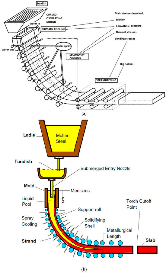
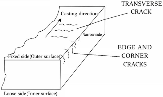
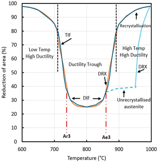
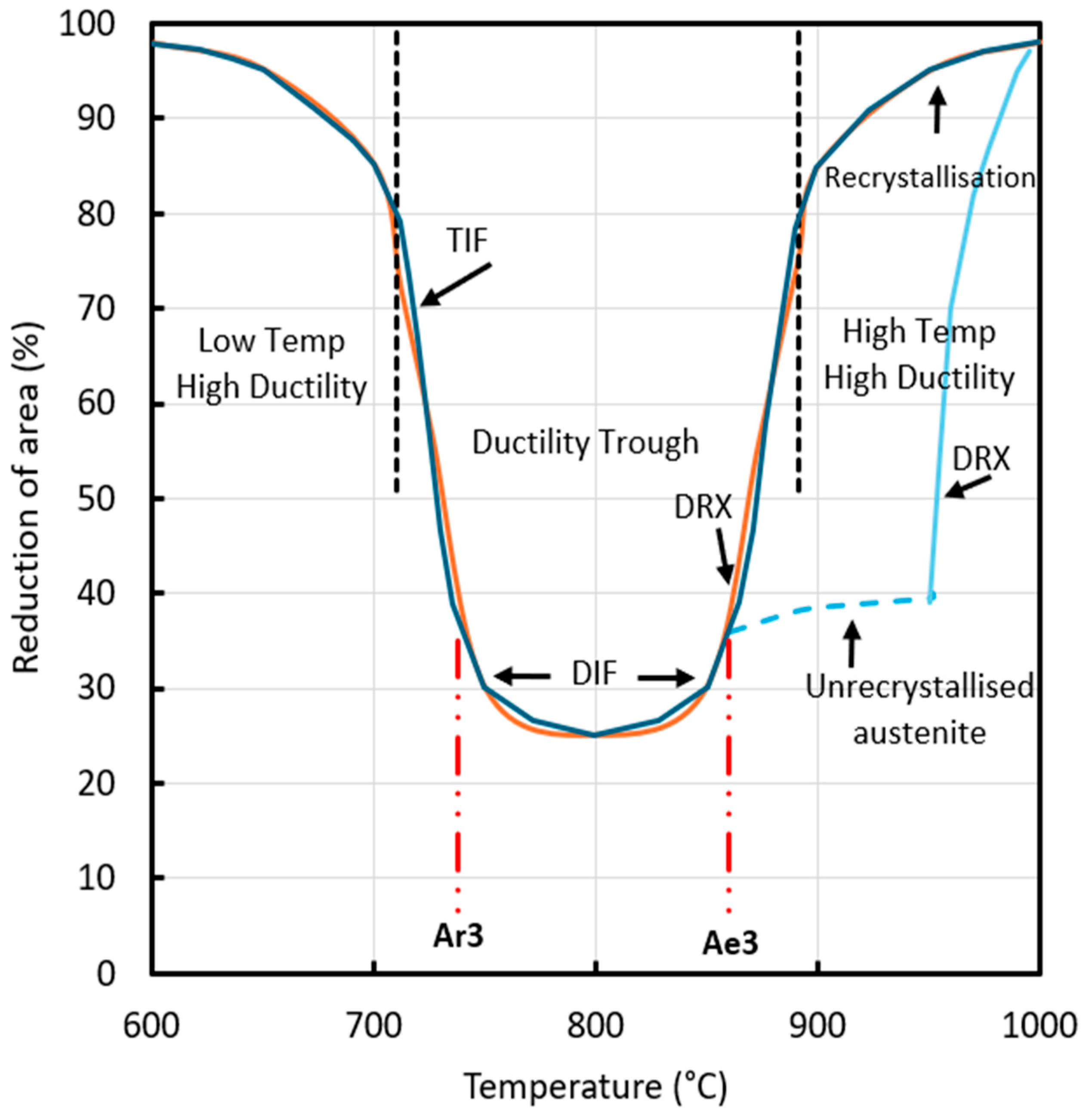
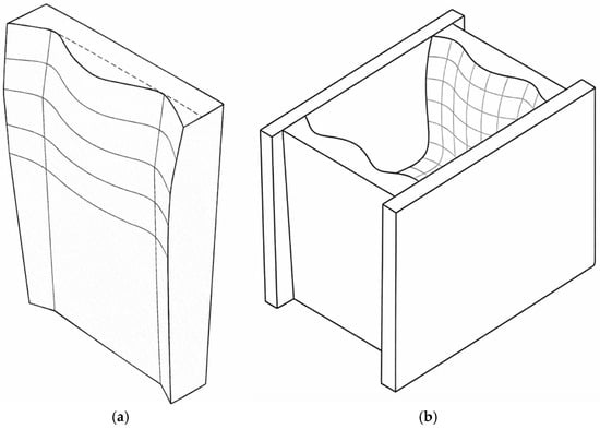
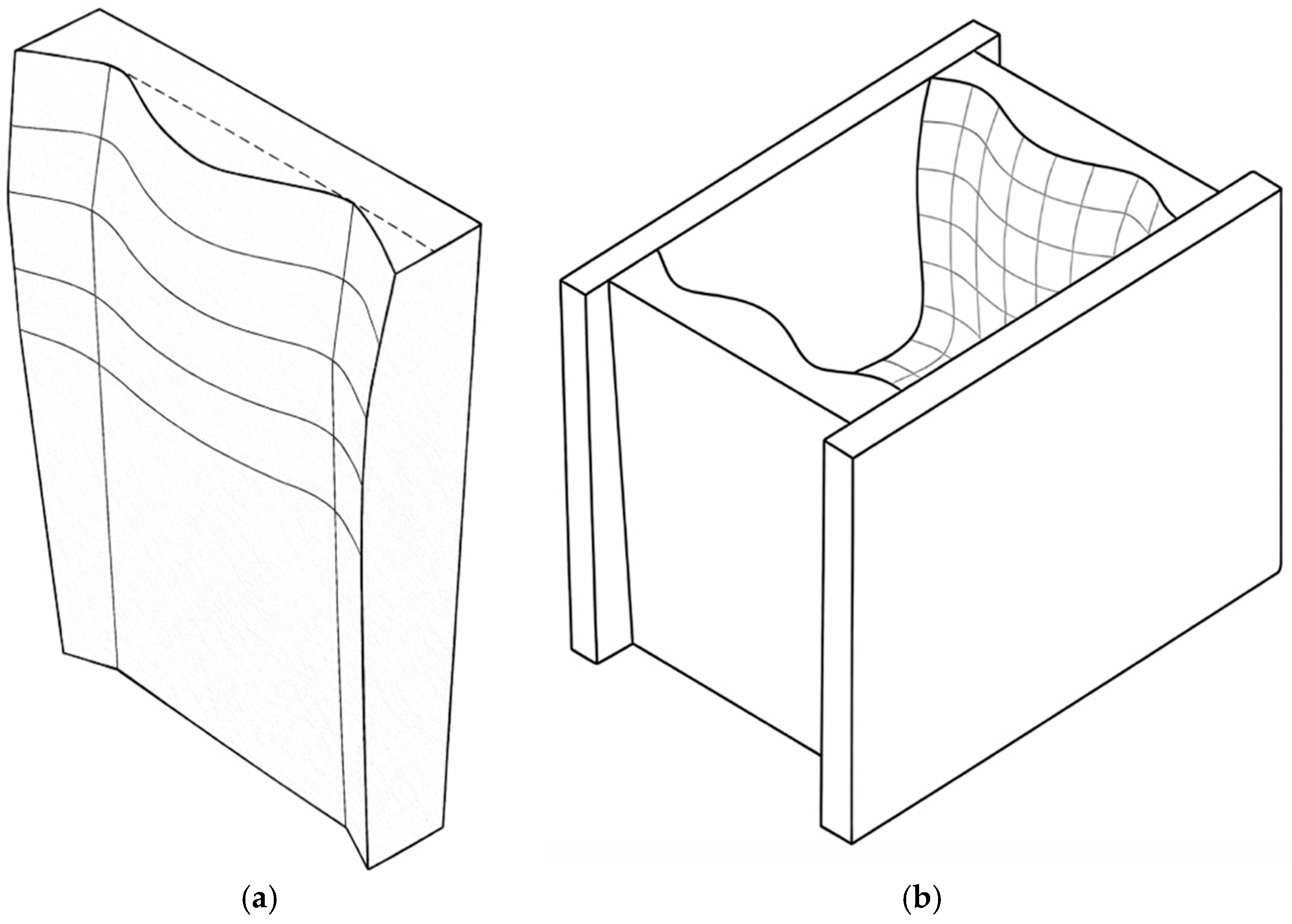
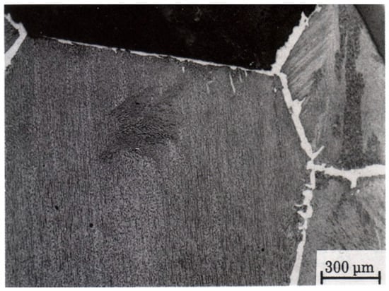
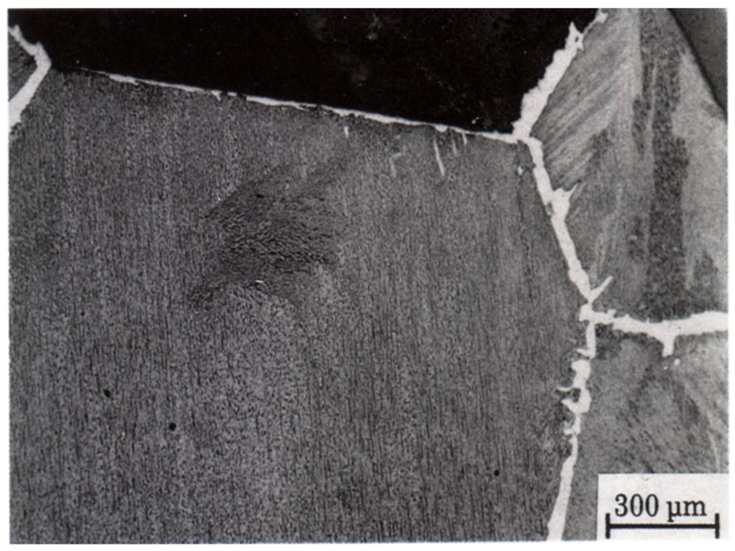
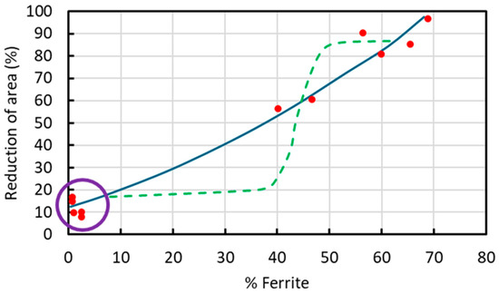
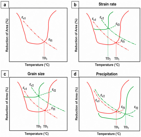
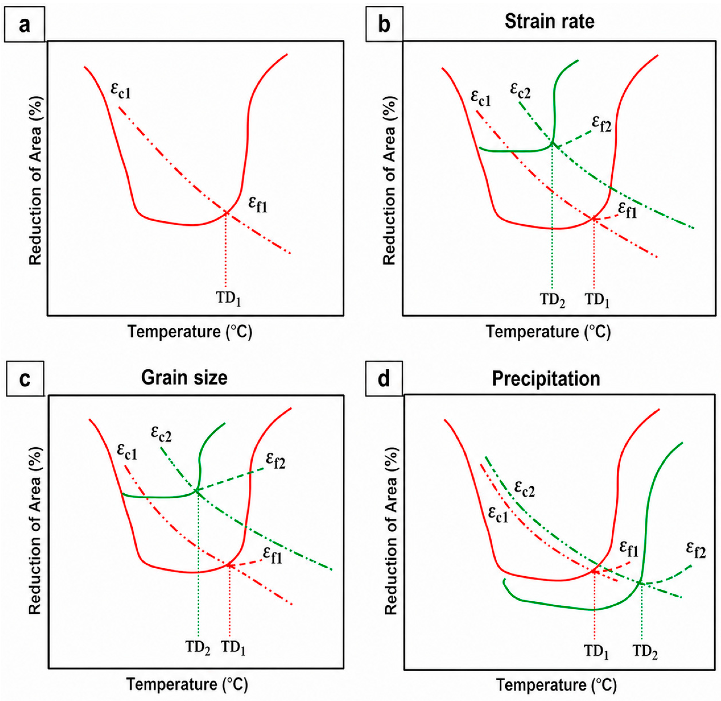
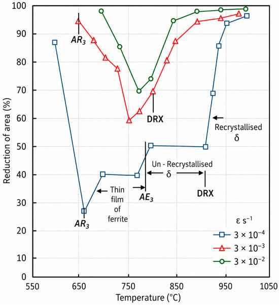
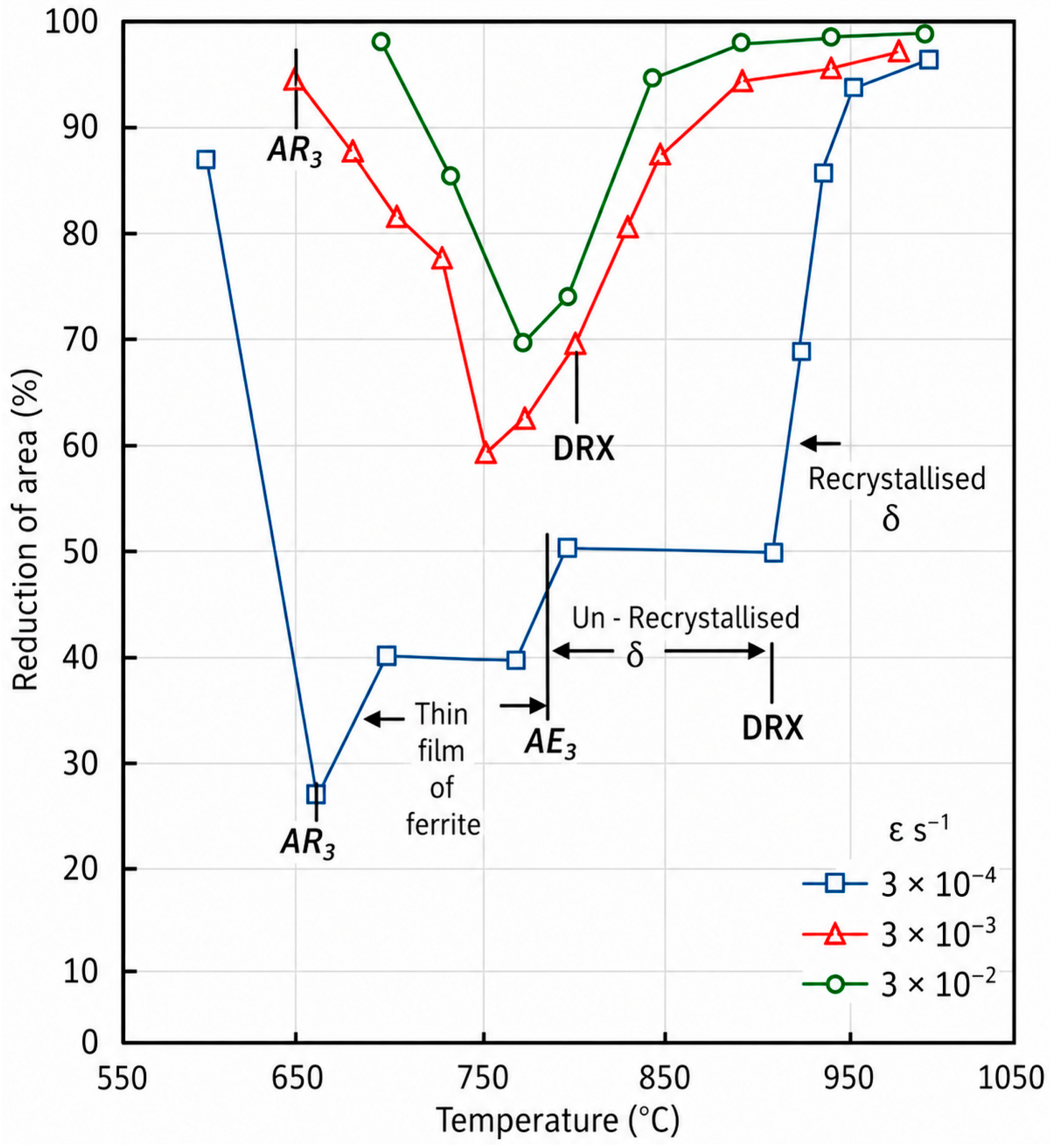
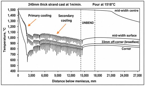
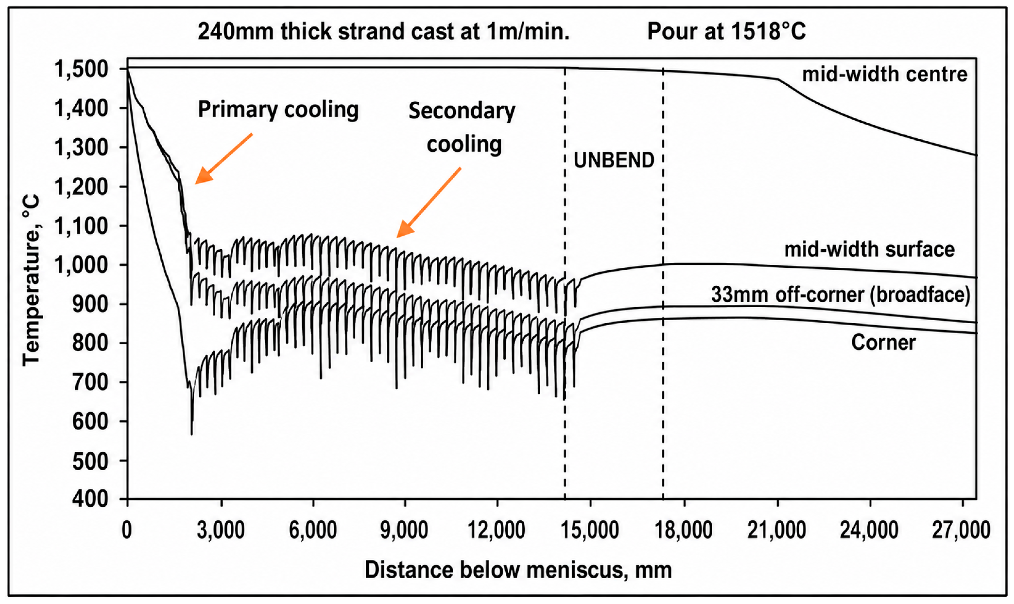
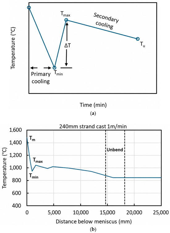
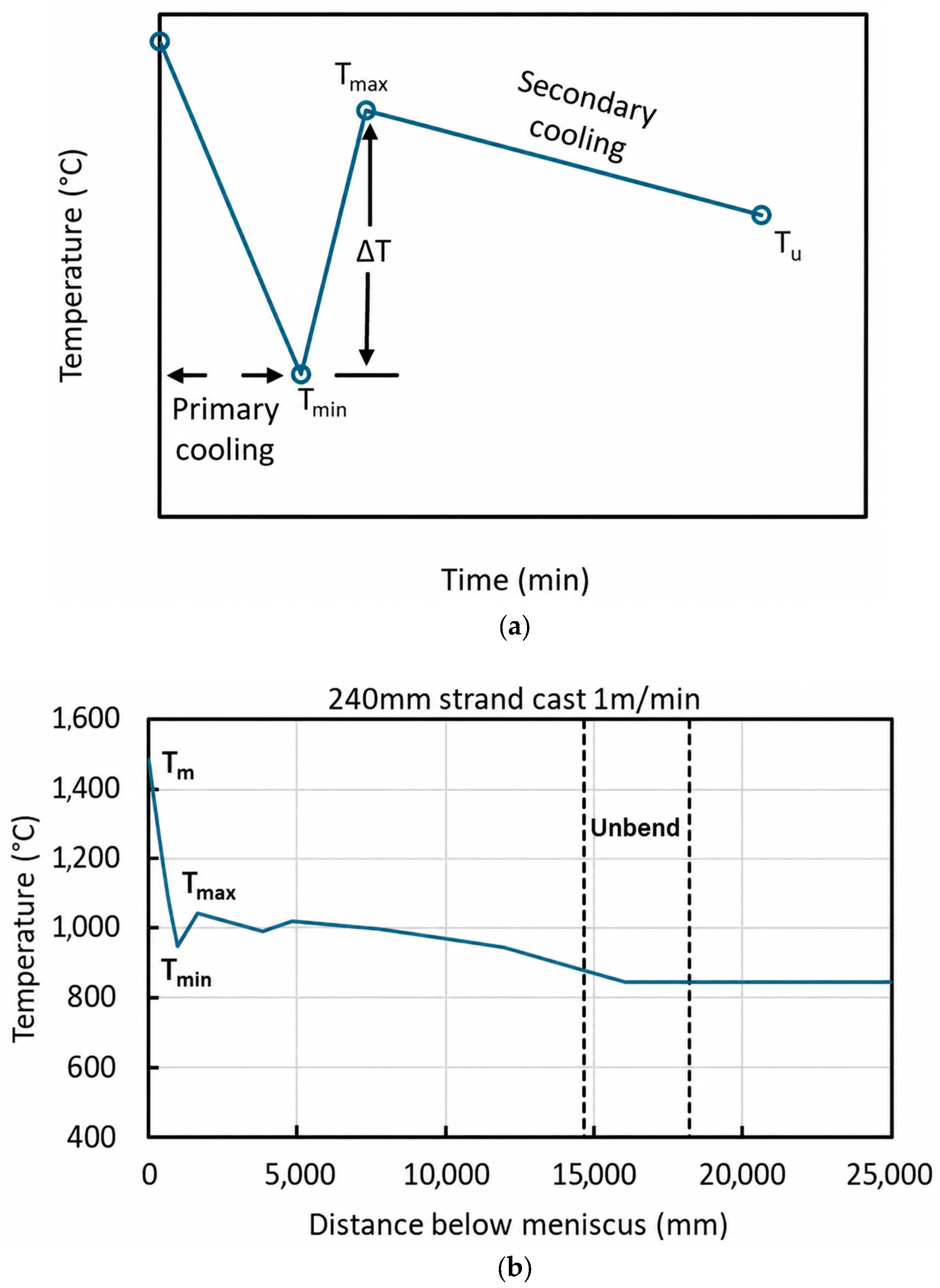
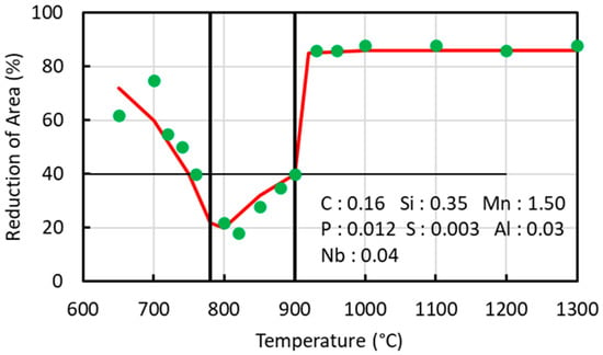
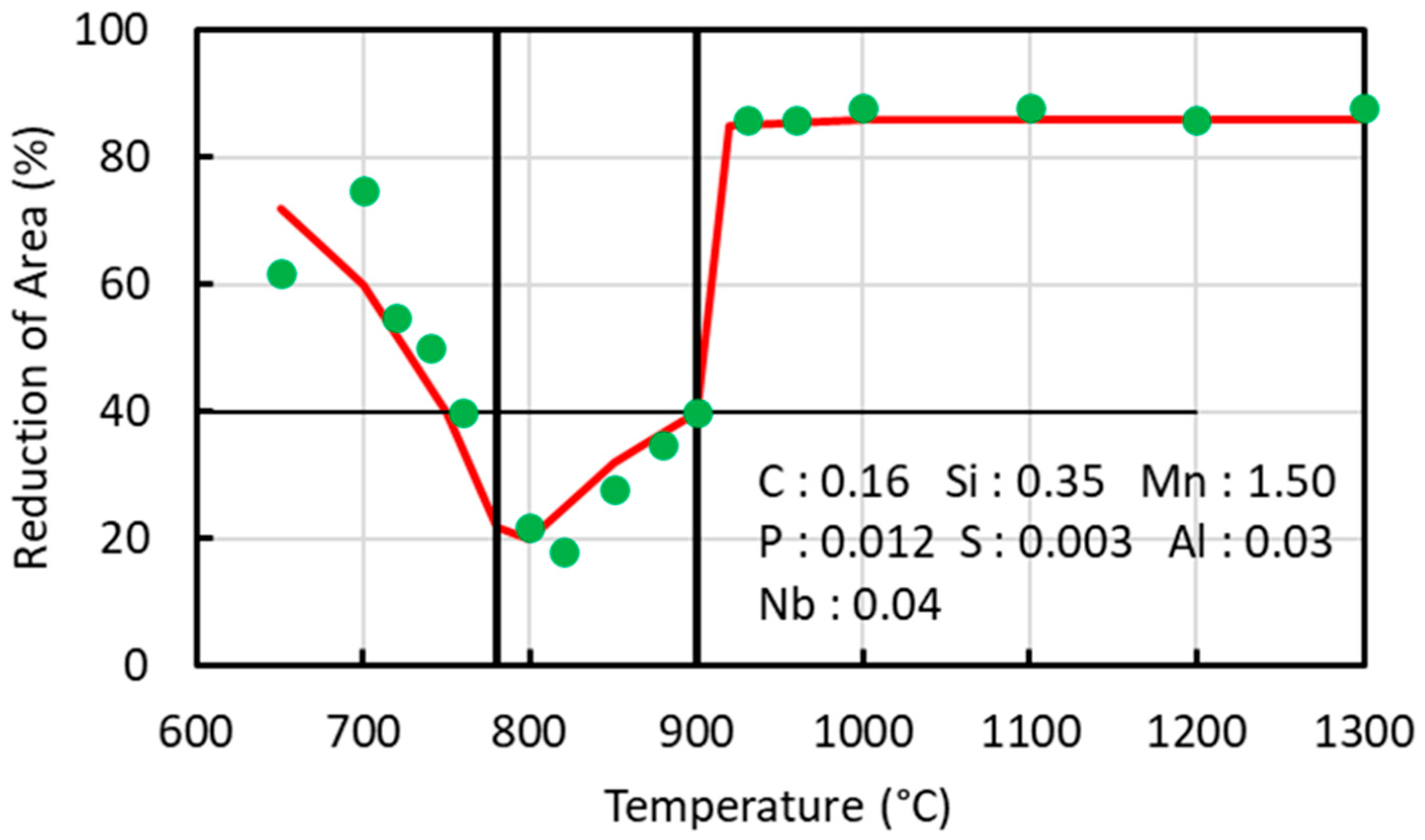
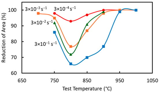
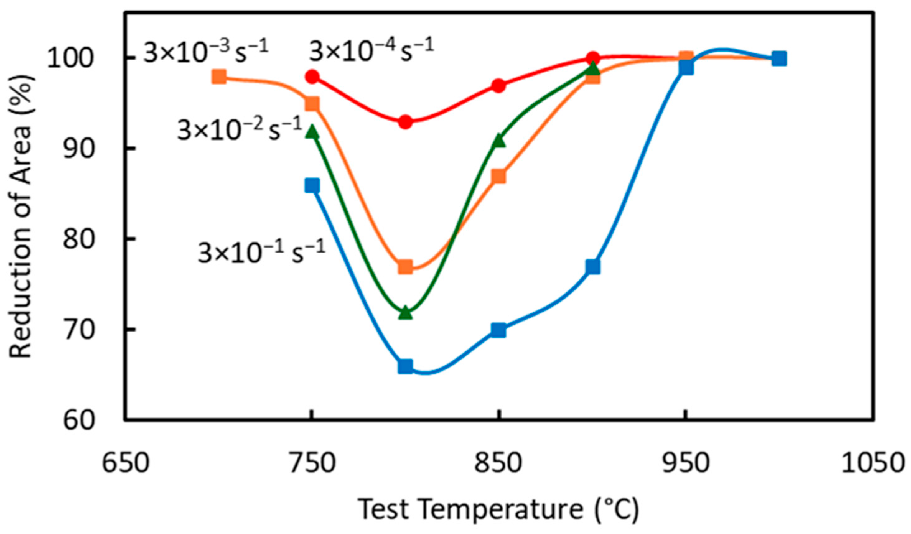
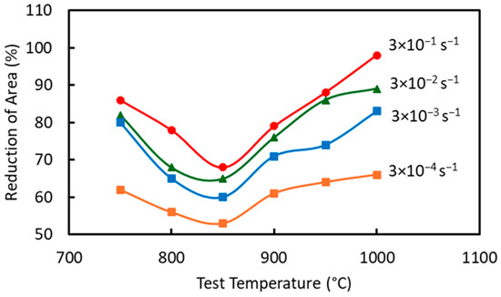
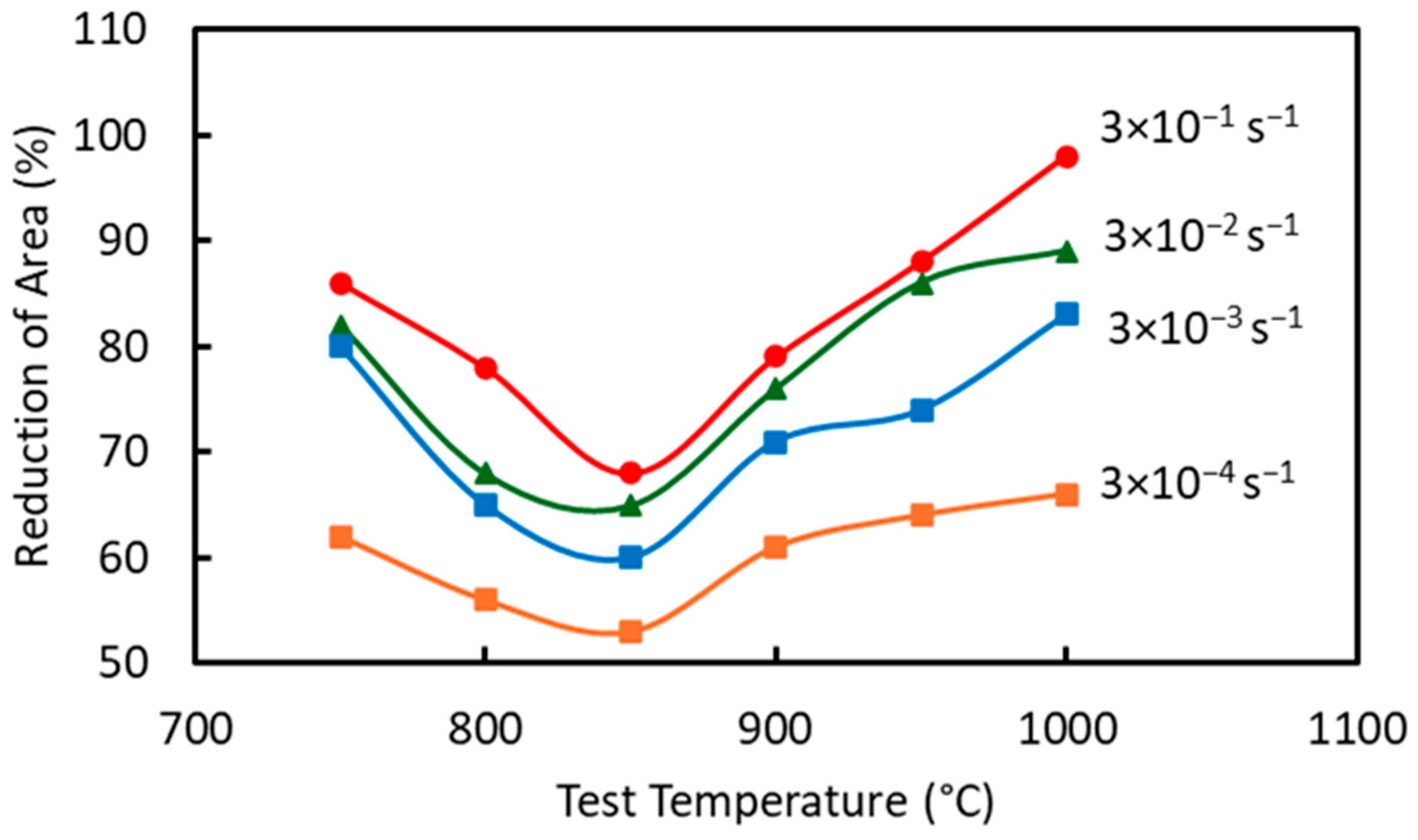
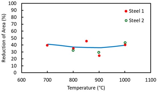
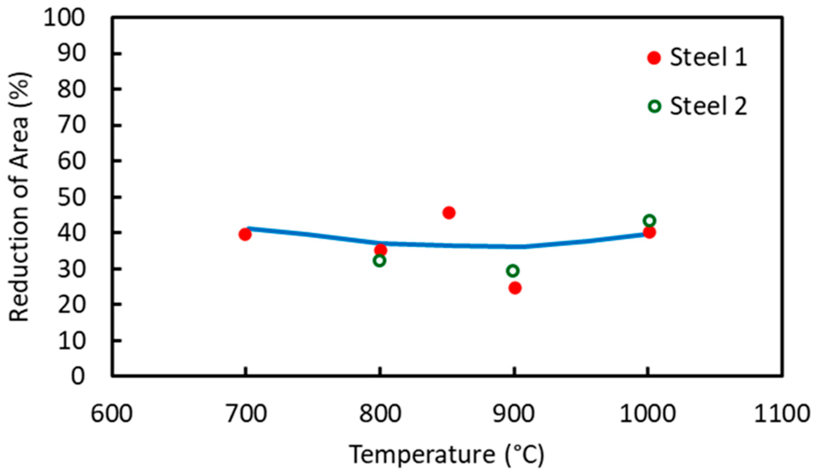
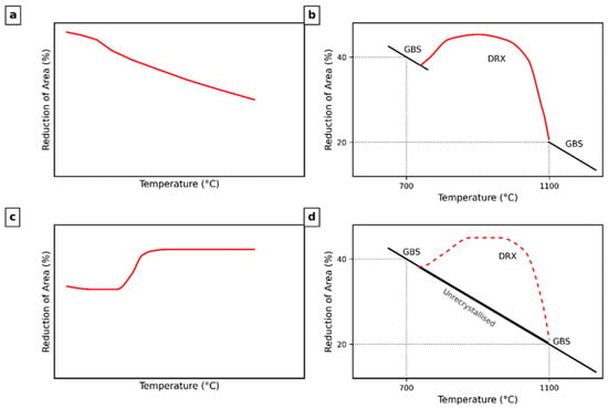
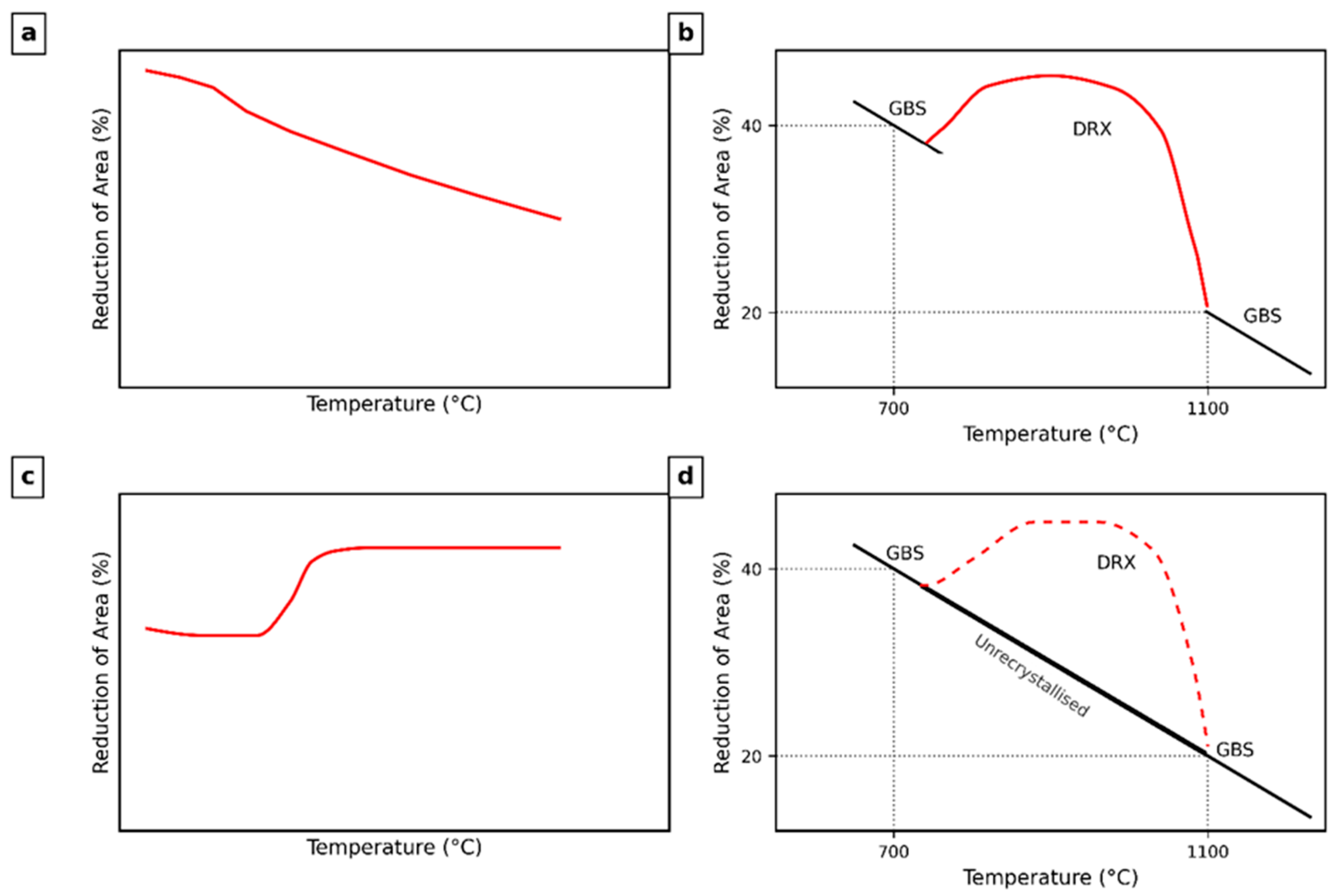
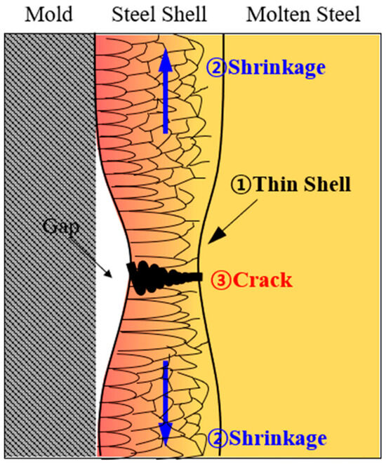
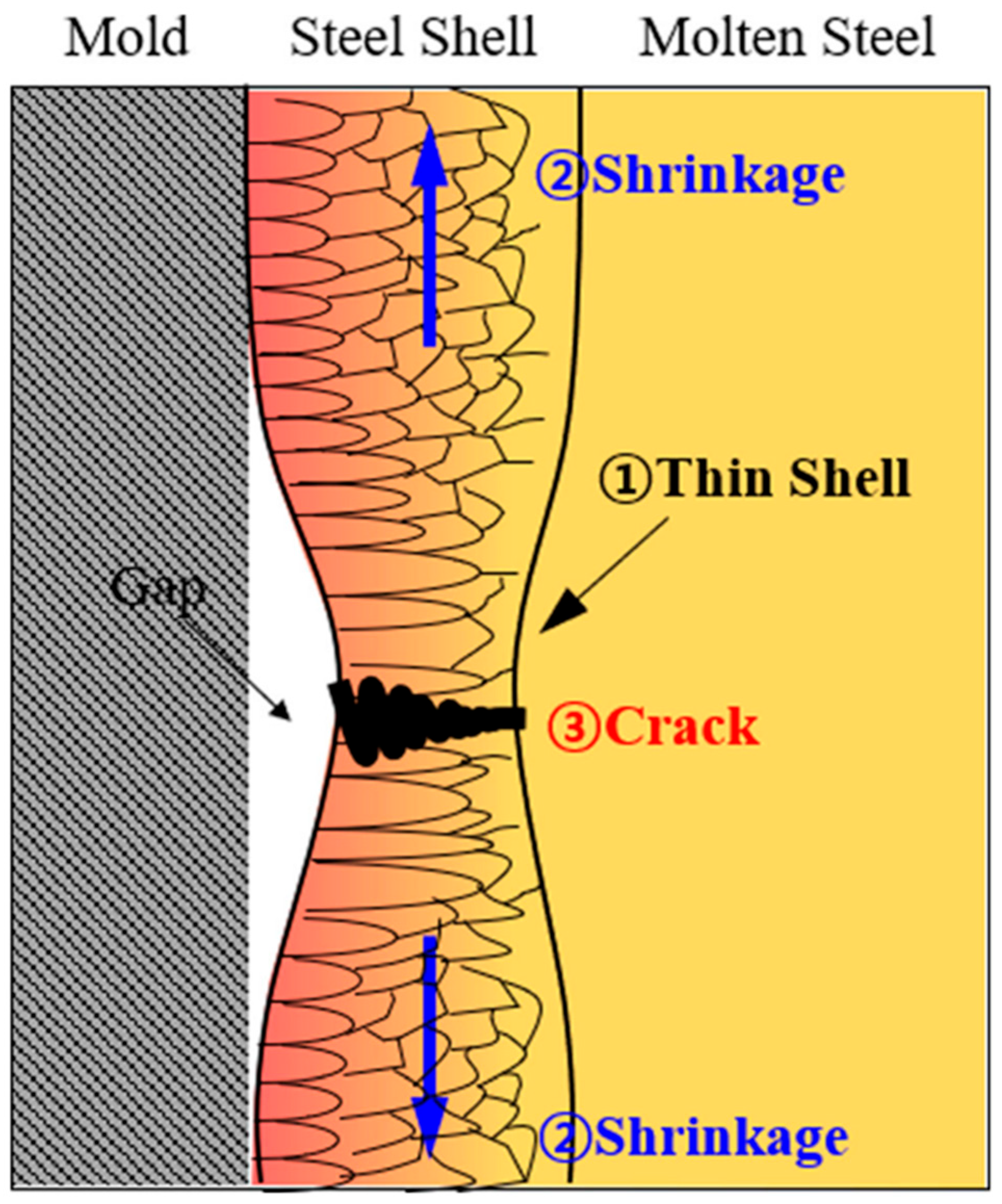
Disclaimer/Publisher’s Note: The statements, opinions and data contained in all publications are solely those of the individual author(s) and contributor(s) and not of MDPI and/or the editor(s). MDPI and/or the editor(s) disclaim responsibility for any injury to people or property resulting from any ideas, methods, instructions or products referred to in the content. |
© 2026 by the authors. Licensee MDPI, Basel, Switzerland. This article is an open access article distributed under the terms and conditions of the Creative Commons Attribution (CC BY) license.