


Abstract
This study develops a two-dimensional computational fluid dynamics model for the reactive zone of an industrial-scale shaft furnace operated under ENERGIRON ZR (zero-reforming) conditions, where carbon in direct reduced iron (DRI) is explicitly distinguished into combined carbon in Fe3C and free carbon in graphitic form. The model is validated against available plant data and then applied to investigate the effects of reducing gas temperature, gas composition, and gas feed rate on reduction, carburization, and carbon partitioning. The results show that in situ reforming, iron oxide reduction, and carburization are strongly coupled near the gas inlet. Increasing the reducing gas temperature from 1273 K to 1373 K raises the metallization degree from 0.9426 to 1.000 and the total carbon mass fraction from 0.01722 to 0.04938, while decreasing the combined carbon fraction from 97.6% to 86.3% because of enhanced Fe3C decomposition. The effect of CH4 content is temperature-dependent: at 1273 K and 1323 K, increasing CH4 from 15% to 25% decreases both metallization and total carbon because intensified endothermic reforming lowers the in-furnace thermal level, whereas at 1373 K the total carbon changes from 0.04849 to 0.04938 and then to 0.04179, reflecting a shift in the controlling factor from CH4 availability to thermal limitation. Increasing gas feed rate from 1400 Nm3/t-pellet to 1600 Nm3/t-pellet improves both reduction and beneficial carburization, with the total carbon mass fraction increasing from 0.02360 to 0.04047, while the combined carbon fraction decreases slightly from 93.9% to 92.5%. The predicted carbon partitioning results also show qualitative agreement with the limited industrial data, particularly the decreasing combined carbon fraction with increasing total carbon content in DRI.
1. Introduction
The iron and steel industry is under increasing pressure to achieve deep decarbonization as it remains one of the largest industrial sources of greenhouse gases, contributing to approximately 7–9% of global anthropogenic carbon dioxide (CO2) emissions [1,2]. Conventional steelmaking based on the blast furnace-basic oxygen furnace (BF-BOF) route, which accounts for roughly 70% of global steel production [3], relies heavily on carbonaceous reductants such as coke and pulverized coal and is therefore inherently limited in achieving substantial emission cuts. In this context, the direct reduction (DR) shaft furnace-electric arc furnace (EAF) route has attracted growing attention as one of the most promising options for low-carbon steelmaking. In this route, iron ore is first converted into direct reduced iron (DRI), which can be discharged either hot or cold, and is subsequently charged into an EAF for steelmaking. Compared with the coal-based BF-BOF route, the DR-EAF route, which uses natural gas as the primary energy source and reductant precursor for generating hydrogen (H2) and carbon monoxide (CO), can reduce CO2 emissions by about 40–60% [4,5].
To further lower the carbon footprint and ultimately approach carbon neutrality, industrial natural-gas-based DR processes, such as MIDREX and HYL/ENERGIRON, are currently transitioning towards H2-rich and even pure H2 variants [6,7]. This transition is generally realized by partially replacing natural gas with externally supplied hydrogen (e.g., green hydrogen). As a result, the H2/CO ratio in the reducing gas increases, which inevitably alters the in-furnace thermochemical state. Thermodynamically, the reduction of iron oxides by H2 is strongly endothermic, whereas reduction by CO is moderately exothermic. Therefore, increasing H2 content tends to lower the thermal level in the shaft furnace, which may weaken reduction kinetics and deteriorate pellet metallization unless compensated by higher gas feed rates or additional thermal input. Another important consequence is the decline in carburization. In conventional DR operation, carburization is mainly associated with methane (CH4)-involved reactions, especially methane decomposition, which is itself endothermic. The intensified heat shortage under H2-rich conditions therefore suppresses carburization and makes it more difficult to maintain a desirable carbon level in DRI.
Although carbon-free DRI may eventually become the target product in a future pure-hydrogen ironmaking scenario, the carbon content of DRI remains a key quality indicator in current industrial practice because it is closely related to downstream melting behavior, energy efficiency, slag foaming, and product stability, particularly in terms of resistance to re-oxidation [8,9]. Therefore, from the perspective of near- to medium-term industrial operation, efficient carburization under low-carbon or hydrogen-rich shaft furnace conditions remains a highly relevant engineering concern. In response to practical production needs, both MIDREX and HYL/ENERGIRON have continued to develop technologies for increasing the carbon level of DRI [10,11]. Among these technologies, the ENERGIRON ZR (zero-reforming) process is of particular interest [12]. In this process, natural gas reforming takes place in situ in contact with metallic iron inside the shaft furnace, thereby eliminating the need for an external reformer. Owing to its relatively high operating temperature, elevated pressure, high H2/CO ratio, and significant CH4 content in the reducing gas, the ENERGIRON ZR process provides favorable conditions for producing high-carbon DRI. Industrial practice has shown that the DRI produced by this process can contain up to about 4.5 wt.% carbon, while the associated CO2 emissions are reported to be lower than those of other DR processes [13,14].
However, carbon in DRI is not present in a single form. It mainly exists as combined carbon in iron carbide (Fe3C) and as free carbon, usually graphitic carbon. These two forms of carbon have markedly different metallurgical implications. A high Fe3C fraction is generally beneficial because it improves DRI stability, suppresses re-oxidation tendency, contributes chemical energy during melting, and supports more efficient downstream steelmaking [15]. By contrast, excessive graphitic carbon is usually undesirable because it is associated with lower DRI stability and less efficient carbon utilization. Moreover, carbon precipitation on or near pore surfaces may obstruct gas access and thereby affect subsequent carburization behavior. This distinction becomes particularly important under the high-carbon conditions characteristic of the ENERGIRON ZR process. Industrial evidence indicates that, although the total carbon content in DRI can be increased to relatively high levels, the fraction of free carbon also tends to rise with increasing total carbon content [14]. Accordingly, the practical objective is not simply to maximize total carbon, but rather to promote the formation of Fe3C while suppressing excessive graphitic carbon.
Numerical modeling provides an effective means to describe and better understand the complex multiphase reactive flow in direct reduction shaft furnaces. In recent years, various mathematical models have been developed, including one-dimensional algebraic models and computational fluid dynamics (CFD) models. Many of these studies have focused primarily on the upper reduction zone, where the dominant concern is the reduction of iron oxides by H2 and/or CO [16,17,18,19,20,21,22,23,24,25,26,27,28,29]. Some more advanced models have extended the domain to the full shaft furnace, including the transition and cooling zones, and have incorporated carburization-related reactions, such as CH4 decomposition and CO precipitation [30,31,32,33,34,35,36,37,38,39,40,41]. Nevertheless, most existing studies focus on the MIDREX process, while numerical investigations of the ENERGIRON process, particularly the ENERGIRON ZR variant characterized by high temperature (>1050 °C), elevated pressure (6–8 bar), and a high H2/CO ratio (4–5), remain limited despite its strong capability to produce high-carbon DRI. Moreover, in most reported models, the carbon in DRI has been treated as a single quantity, i.e., total carbon, without explicitly distinguishing between Fe3C and graphitic carbon. This simplification may be acceptable when the carbon level is relatively low (<2 wt.%), as is often the case in MIDREX-type operations, but becomes questionable under the high-carbon conditions of the ENERGIRON ZR process.
In this context, a recent one-dimensional integrated two-scale shaft furnace model developed by Kumar et al. [41] represented an important step forward by simultaneously considering graphitic carbon and Fe3C formation during carburization in MIDREX and HYL/ENERGIRON shaft furnaces. However, this approach remains fundamentally one-dimensional and therefore cannot capture radial variations in gas composition, temperature, reduction degree, and carbon form distribution, which are becoming increasingly significant as industrial shaft furnaces continue to grow in size and internal radial non-uniformity can no longer be neglected [42]. To address this gap, the present work develops a two-dimensional CFD model for the reactive zone of an industrial-scale shaft furnace operated under ENERGIRON ZR conditions, in which Fe3C and graphitic carbon are explicitly distinguished in the solid phase. The model is first validated against available plant data, and is then applied to investigate the evolution and relative proportions of Fe3C and graphitic carbon under different operating conditions, including reducing gas composition (CH4 content), feed rate, and temperature. The findings of this study are expected to provide technical guidelines for promoting beneficial carburization in shaft furnaces during the green transition of ironmaking.
2. Modeling
2.1. Process Description
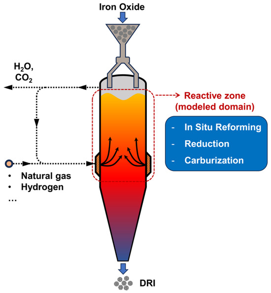
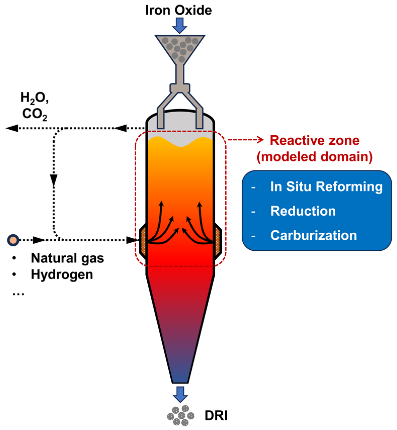
Figure 1 schematically illustrates ENERGIRON ZR shaft furnace and the reactive zone considered in the present study. Unlike conventional natural-gas-based DR processes equipped with an external reformer, the ENERGIRON ZR configuration eliminates the need for dedicated gas-reforming equipment by promoting reforming reactions directly inside the shaft furnace. In the gas recycling loop, the top gas leaving the furnace is first sent to a condenser for water removal, and the dried off-gas is then introduced into a CO2 removal unit to reduce the CO2 level before recycling. After mixing with fresh natural gas, steam, and, if needed, other gas sources such as hydrogen, the recycled gas is heated and re-injected into the shaft furnace as reducing gas. Owing to this flexible process arrangement, the reducing gas composition can be adjusted over a relatively wide range. A characteristic feature of the ZR process is that the reducing gas entering the furnace typically retains a relatively high CH4 content because no external reformer is employed.
Figure 1.
Schematic illustration of ENERGIRON ZR shaft furnace and the reactive zone considered in the present study.
In practical operation, iron oxide pellets are charged from the top of the furnace and descend by gravity through the burden bed, while the reducing gas is injected circumferentially through the bustle pipe located at the middle height of the furnace and flows upward in a countercurrent manner. Under the high-temperature, high-pressure conditions of the ENERGIRON ZR process, CH4-containing gas undergoes in situ reforming in the presence of metallic iron, generating H2 and CO as the main reducing species. These gases reduce iron oxides to metallic iron, while the gaseous products of reduction, mainly H2O and CO2, further participate in reforming-related reactions. As a result, reforming and reduction are strongly coupled inside the shaft furnace. At the same time, carburization is also expected to occur in the shaft furnace, particularly in the vicinity of the gas inlet, owing to the relatively high CH4 content in the reducing gas and the favorable local thermochemical conditions in this region. Therefore, under ENERGIRON ZR conditions, in situ reforming, iron oxide reduction, and carburization occur simultaneously and interact with one another, forming a distinctive reactive zone in the upper part of the shaft furnace, as highlighted in Figure 1. This feature distinguishes this process from conventional DR shaft furnaces, in which the functional zones are more clearly separated. Depending on the process configuration, the produced DRI can be discharged either at a low temperature (e.g., about 50 °C) as cold DRI or at a relatively high temperature (e.g., above 600 °C) as hot DRI.
2.2. Model Basics and Numerical Treatment
The CFD model developed in the current work was derived from a simplified one developed by the present authors in an earlier publication [39], in which ten chemical reactions were considered, including the reduction of iron oxides by H2 (R1–R3 in Table 1) and by CO (R4–R6 in Table 1), water–gas shift reaction (R7 in Table 1), and methane steam reforming (R8 in Table 1) and carburization reactions by methane decomposition and carbon monoxide precipitation. However, the carbon in DRI was not distinguished into different forms but was instead treated as a single quantity. In the present model, by contrast, iron carbide, namely cementite (Fe3C) and graphite (C), are explicitly distinguished, as shown by R9–R11 in Table 1, corresponding to methane decomposition, carbon monoxide precipitation, and cementite decomposition, respectively. The enthalpy change in each reaction is also listed in Table 1.
Table 1.
Reactions considered in the CFD model.
The Eulerian two-fluid approach adopted in the previous model is retained in this work, treating both the gas and the solid as interpenetrating continua and solving their conservation equations separately. The shaft furnace is assumed to operate under steady-state conditions. Therefore, the generalized conservation equation for each phase can be written as
where subscript p denotes gas (g) or solid (s) phase, εp, ρp, ϕp, and up are the volume fraction, density, field variable to be solved, and velocity vector of phase p, respectively, and Γϕ and Sϕ stand for the generalized diffusion coefficient and source term with respect to corresponding field variable ϕ. The specific forms of ϕ, together with the corresponding Γϕ and Sϕ in each conservation equation, are summarized in Table 2.
∇·(εpρpϕpup) = ∇·(εpΓϕ∇ϕp) + Sϕ,
Table 2.
Variables for the conservation equations of Equation (1).
In Table 2, P denotes the absolute pressure, h is the specific enthalpy, λ and Cp are the thermal conductivity and specific heat capacity, w and D stand for the intra-phase mass fraction and diffusion coefficient of species, M is the molecular mass of species, while ΔH is the reaction enthalpy, as listed in Table 1.
The momentum transfer rate between the gas and solid phases is given by Ergun’s equation in vector form:
where μg refers to the dynamic viscosity of the gas phase, while ds stands for the effective diameter of the solid phase.
The heat transfer rate between the gas and solid phases, Egs, is expressed using the modified Ranz equation by Akiyama [43]:
where Tg and Ts denote gas and solid temperature, and Re and Pr are the relative Reynolds number on the basis of ds and the Prandtl number of the gas phase, respectively.
The gas phase is assumed as ideal gas and its density is expressed as
where R* represents the universal gas constant while subscript i denotes the gaseous species.
The reaction rates of R1–R6 obey the mechanism of the unreacted shrinking core model (USCM), which is well-established and widely used in shaft furnace modeling. For simplicity, the detailed rate expressions are not presented here; the reader is referred to Ref. [44] for the original formulation. Meanwhile, the corresponding correlations for kinetic parameters, including the equilibrium constant, rate constant, and effective diffusion coefficient, can be found in the earlier publications of the present authors [39].
The rates of R7 and R8, both of which are reversible homogeneous gas-phase reactions, are expressed as
where the correlations of reaction rate constants (k7 and k8) and equilibrium constants (K7 and K8) are listed in Table 3. It is seen that the rate constants are associated with the reduction degree (X) of pellets. The reason lies in the fact that the water–gas shift reaction is catalyzed by metallic iron and its oxides to different extents, while the methane reforming reaction is catalyzed solely by metallic iron. Here, X = 0.5 represents the appearance of metallic iron.
As a central aspect of the present model, carburization modeling is of particular importance in this work. Kumar et al. [41] considered the methane decomposition into iron carbide or graphite as two parallel processes in their one-dimensional models. However, experimental evidence reported in the literature suggests that the occurrence of graphite is more likely to result from the cementite decomposition, as the iron carbide is a metastable phase and can easily decompose to metallic iron and graphite, even under strongly carburizing atmospheres [45,46,47]. Therefore, the present model represents carbon form evolution as a progressive Fe3C-formation-decomposition pathway, as represented by R9–R11 in Table 1. It should be noted that the graphite can be generated directly through methane decomposition and carbon monoxide precipitation in reality; however, these pathways are not explicitly considered in the current work.
The reaction rates of CH4 decomposition (R9) and CO precipitation (R10) are given by
Corresponding kinetic constants are also outlined in Table 3.
The carbon activity in DRI, aC, which is assumed to govern carburization rate and subsequent cementite decomposition rate, is calculated from Chipman’s correlation:
where C denotes the atomic ratio of carbon to metallic iron.
Following the correlation proposed by Longbottom et al. [46] based on experimental results, the reaction rate of cementite decomposition is expressed as
where b is a temperature-independent coefficient, and DC,iron is a carbon diffusion coefficient, representing the carbon diffusion in iron phase, with a correlation of
where c′ denotes graphite in weight percent. The general principle is that DC,iron increases significantly with increasing temperature, leading to a growth trend of R11 with temperature, although aC decreases moderately with temperature.
Table 3.
Correlations of kinetic parameters for homogeneous gas-phase and carburization reactions [35,48,49].
In this work, the governing conservation equations (Equation (1)) are solved using the finite volume method, in which the convective terms are discretized with a second-order upwind scheme and the diffusive terms are discretized using the central difference scheme to ensure an accurate and robust calculation. The coupling between velocity and pressure is achieved using the coupled SIMPLE algorithm. The calculation is considered converged when the residuals of all discretized equations become less than 1 × 10⁻⁷, with the under-relaxation factors carefully adjusted during the solution process.
2.3. Model Validation and Boundary Conditions
Since publicly available industrial data for the ENERGIRON ZR process remain very limited, the accuracy of the present CFD model was assessed by reproducing published industrial measurements from a MIDREX shaft furnace with a productivity of 26.4 t-DRI/h. This industrial furnace has been widely used in previous modeling studies: detailed information regarding its geometry, operating conditions, and material properties can be found in Refs. [34,35,50].
Table 4 compares the predicted values with the reported plant data for several key performance indicators, including gas composition, DRI metallization degree, and carbon content. Reasonable agreement is obtained for all these variables, indicating that the model is capable of reproducing the essential transport and reaction behavior in an industrial shaft furnace. For the carbon content, the model predicts that Fe3C is the dominant carbon-bearing phase, accounting for approximately 99% of the total carbon. Since one of the key features of the present model is the explicit distinction between Fe3C and graphitic carbon, the validity of the predicted proportion between these two carbon forms will be further discussed in the subsequent simulation results. It should also be noted that the present comparison with MIDREX plant data should be regarded as validation of the general transport, heat-transfer, reduction, and reaction framework rather than as direct validation of the model under ENERGIRON ZR conditions. Further quantitative validation against detailed ENERGIRON ZR plant data, particularly measurements distinguishing the two carbon forms, is required when such data become available.
Table 4.
Comparisons between the MIDREX plant data and model predictions.
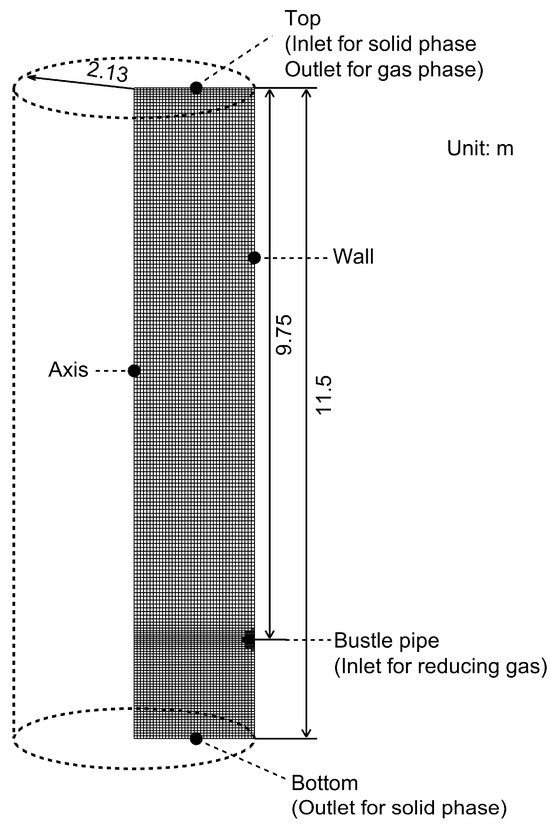
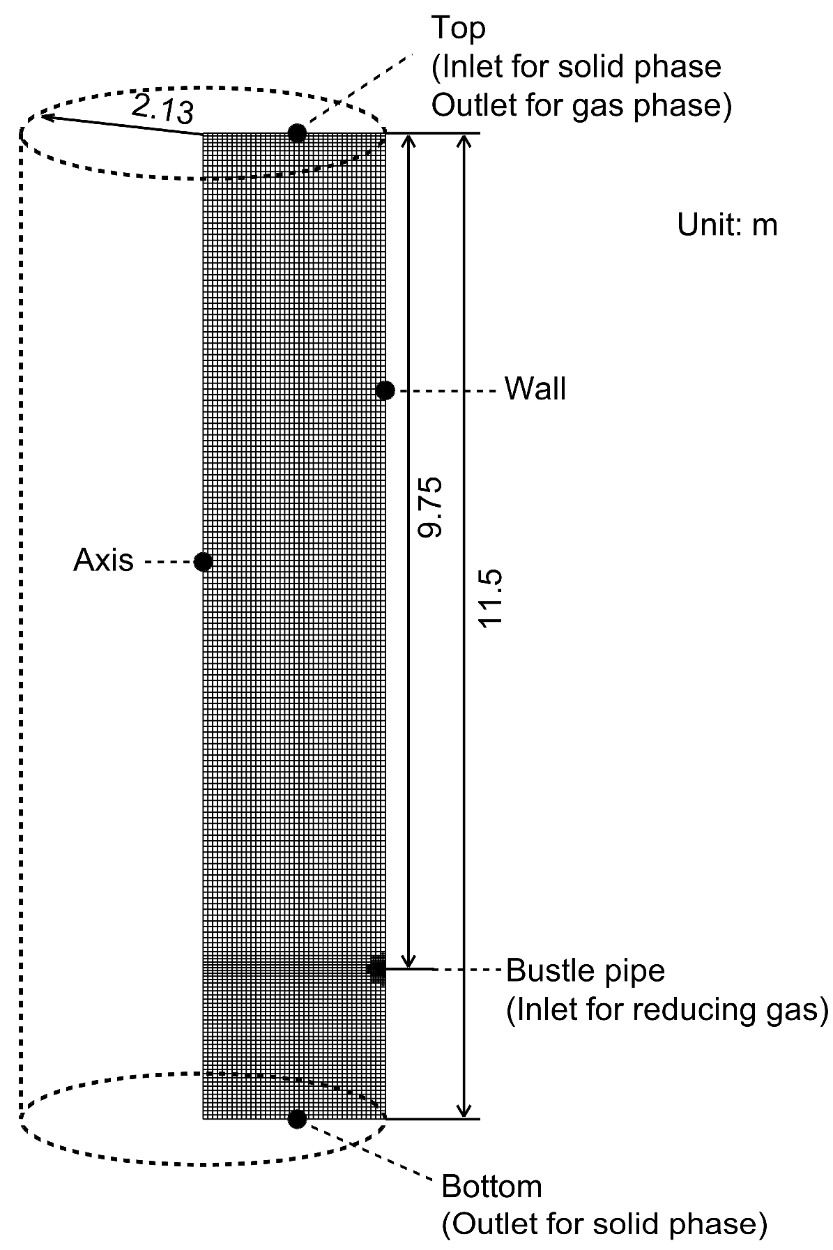
In the following simulations, the computational domain is restricted to the upper reactive zone of the shaft furnace, whose geometric parameters, boundary conditions, and corresponding spatial discretization are illustrated in Figure 2. This section is taken directly from the reduction-zone geometry of the reference MIDREX furnace. The mesh resolution was confirmed to be sufficient based on a grid independence test [25]. The solid flow pattern, including pellet velocity, pellet size, and bed voidage, is also kept consistent with that of the reference MIDREX furnace. On this basis, the gas operating conditions are modified to represent ENERGIRON ZR-like conditions, characterized by a high top-gas pressure of 6 bar, a high H2/CO ratio of 4.0, elevated gas temperatures above 1273 K, and relatively high CH4 contents in the reducing gas, exceeding 15%. The present study focuses on this upper reactive zone because, under ENERGIRON ZR conditions, in situ reforming, iron oxide reduction, and carburization are expected to occur predominantly in this region.
Figure 2.
Geometry and corresponding spatial discretization of computational domain.
3. Results and Discussion
Table 5 summarizes the operating conditions and corresponding performance indicators of DRI for all simulation cases considered in the present study. The base case corresponds to a representative ENERGIRON ZR operating condition, with a reducing gas temperature of 1323 K, a gas feed rate of 1500 Nm3/t-pellet, and a gas composition of 60% H2, 15% CO, 20% CH4, 1% H2O, 1% CO2, and 3% N2. Based on this reference condition, parametric studies were carried out to investigate the effects of reducing gas temperature, gas composition, and gas feed rate, as summarized in Table 5. It should be noted that, in the composition variation cases, the H2O, CO2, and N2 contents as well as the H2/CO ratio were kept constant. The relatively low H2O and CO2 levels were selected to reflect the process characteristics of the ENERGIRON ZR process, as shown in Figure 1, in which the humidifier and CO2 removal unit allow these gas species to be adjusted to low levels before the recycled gas is re-injected into the shaft furnace. In addition, all performance indicators listed in Table 5 are mass-weighted average values at the furnace bottom. For convenience in cross-referencing the cases discussed in the following subsections, some cases appear in more than one parametric group, as noted at the bottom of the table.
Table 5.
Summary of operating conditions and outlet-averaged metallization and carbon partitioning results for all simulation cases.
3.1. In-Furnace Thermochemical State
In this subsection, the in-furnace thermochemical state under the operating conditions of the base case is presented in detail.
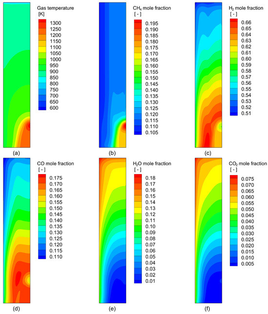
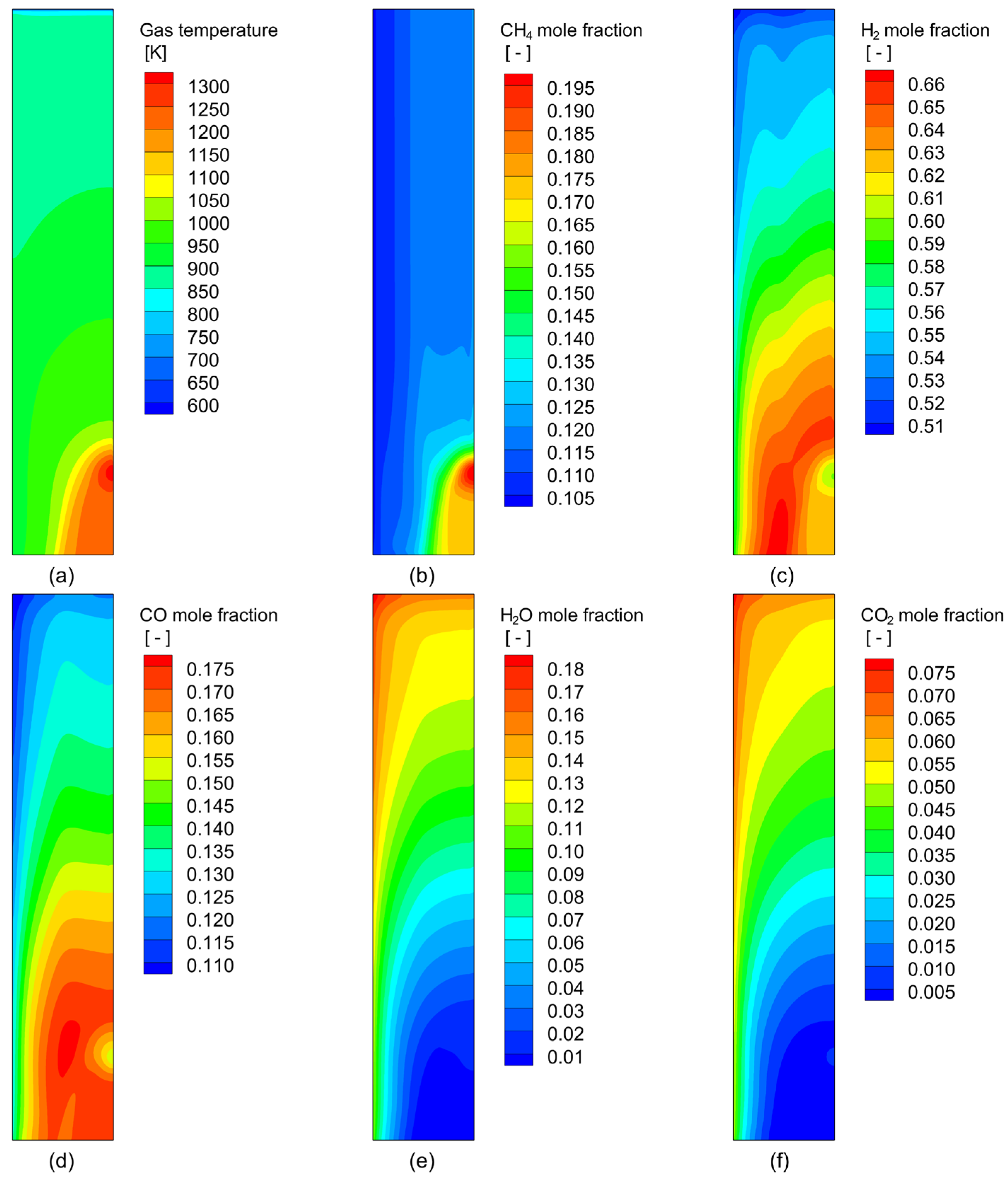
Figure 3 shows the distributions of gas temperature and gas-phase composition in the furnace. A pronounced high-temperature region is observed in the vicinity of the gas inlet, where the hot reducing gas is injected. As the gas flows upward, its temperature gradually decreases, indicating continuous heat consumption by endothermic reactions, including H2 reduction, CH4 reforming, and CH4 decomposition, together with heat transfer to the descending burden bed. The CH4 mole fraction is highest near the gas inlet and decreases rapidly as the gas penetrates into the bed, confirming its active participation in the in situ reforming and carburization processes. In contrast, H2 and CO are initially enriched in the lower part of the reactive zone and then gradually decrease towards the furnace top due to their continuous consumption in the reduction of iron oxides. Correspondingly, H2O and CO2, as gaseous reduction products, exhibit the opposite trend, with relatively low levels near the gas inlet and progressively higher concentrations towards the upper part of the furnace. These gas-phase distributions clearly indicate that the lower shaft region near the gas inlet is the main zone where reforming and reduction are most strongly coupled.
Figure 3.
Distributions of (a) gas temperature and gas-phase mole fraction of (b) CH4, (c) H2, (d) CO, (e) H2O, and (f) CO2 under the conditions of the base case.
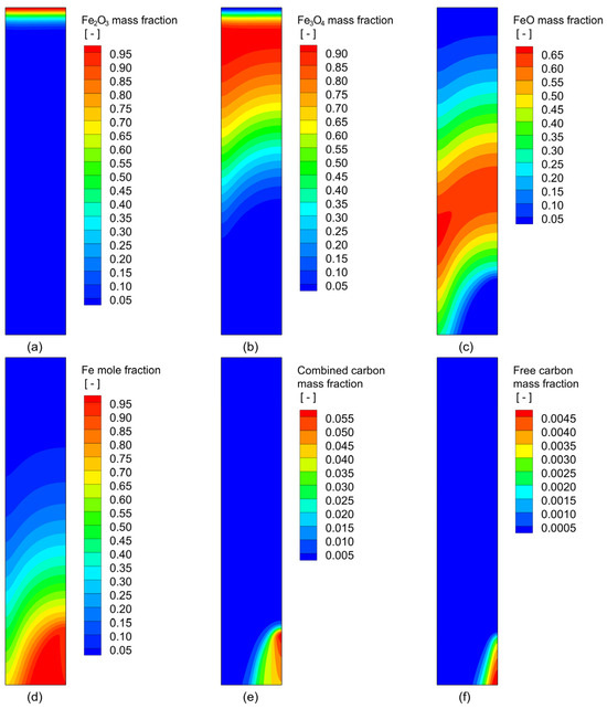
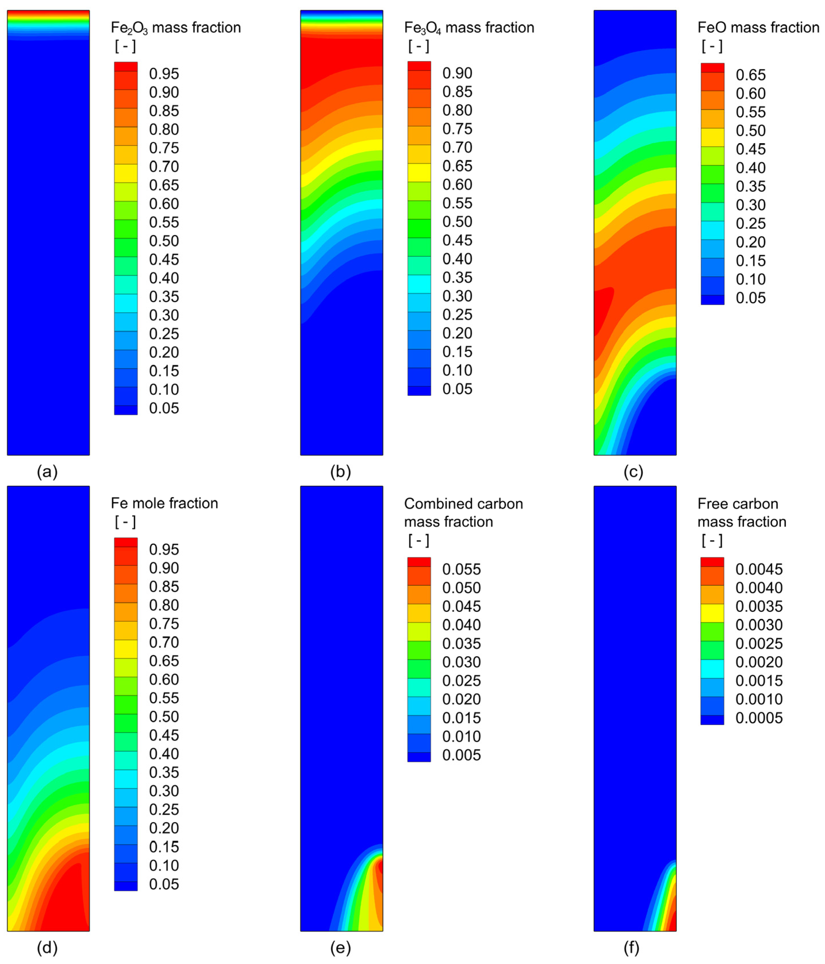
The corresponding solid-phase evolution is presented in Figure 4. The reduction of iron oxide proceeds sequentially along the descending path of the burden. Hematite is mainly preserved in the uppermost part of the furnace, while magnetite and wüstite appear as intermediate phases during the descent of the burden bed. Metallic iron is predominantly formed in the lower part of the reactive zone, where the gas temperature is higher and the reducing potential is stronger. This distribution is consistent with the gas-phase fields shown in Figure 3. Carbon deposition takes place only after sufficient metallic iron has been generated. As a result, combined carbon, i.e., carbon present as Fe3C, is mainly distributed in the lower part of the furnace, especially near the gas inlet where both metallic iron availability and carburizing potential are high. Free carbon shows a more localized distribution and is confined to the most strongly carburized region. The calculation results listed in Table 5 show that most of the deposited carbon remains in the form of Fe3C (93.4%), while only a relatively small fraction is converted into graphitic carbon (6.6%).
Figure 4.
Distributions of solid-phase mass fractions of (a) Fe2O3, (b) Fe3O4, (c) FeO, (d) Fe, (e) combined carbon, and (f) free carbon under the conditions of the base case.
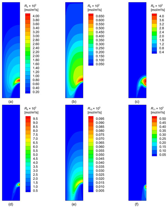
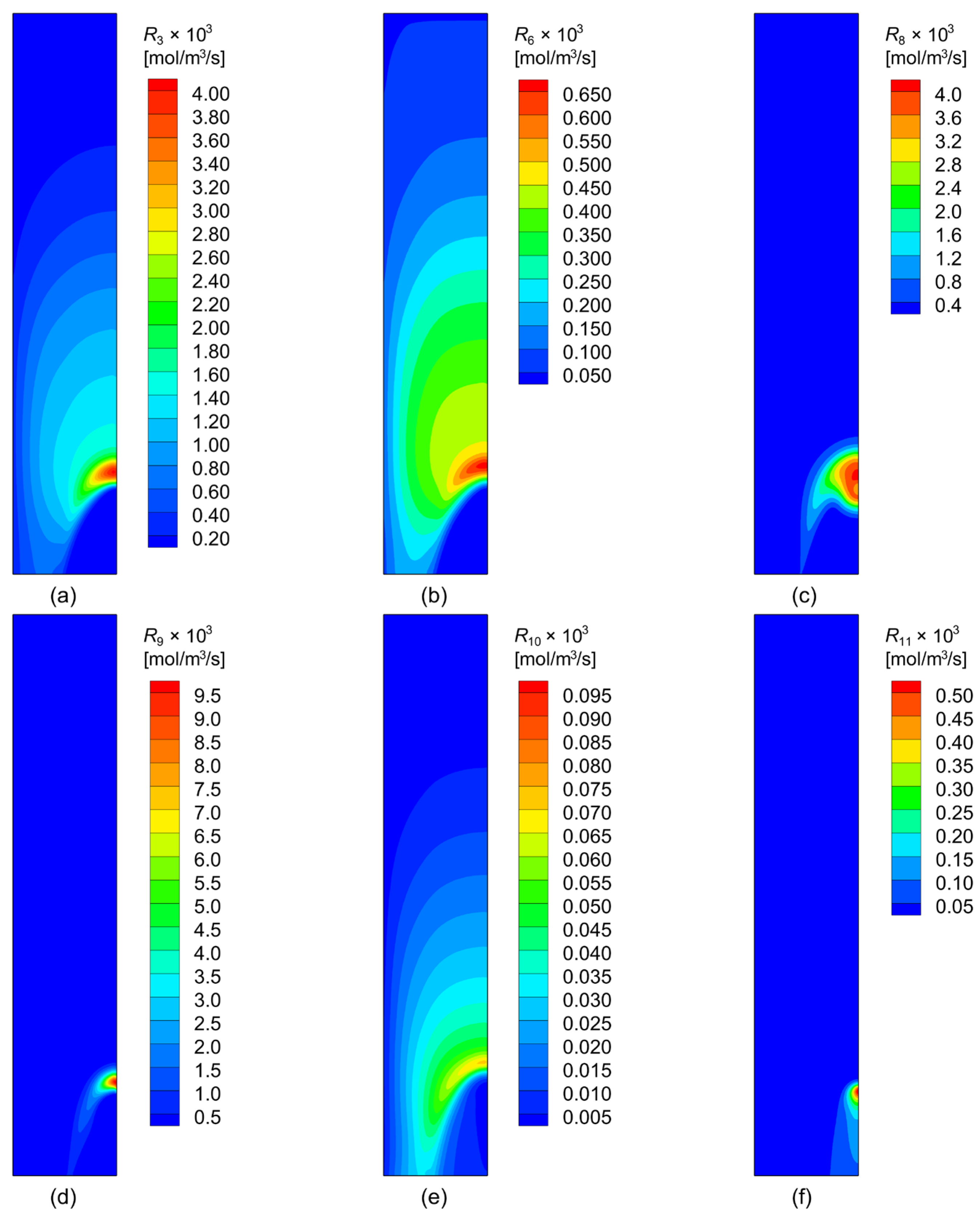
Figure 5 further clarifies the underlying reaction mechanism through the distributions of representative reaction rates. The final reduction of wüstite to metallic iron by H2 and CO, represented by R3 and R6, is concentrated in the lower part of the reactive zone, in agreement with the distribution of metallic iron in Figure 4. By comparison, the H2-based reduction is much stronger than the CO-based route, reflecting the H2-rich nature of the ENERGIRON ZR process. Methane reforming, R8, is strongly localized near the gas inlet, where CH4, H2O, high temperature, and catalytic metallic iron coexist. This reforming reaction continuously generates H2 and CO, which in turn sustain the reduction of iron oxides. The carburization reactions, R9 and R10, are also concentrated in the same region, indicating that carbon uptake occurs mainly after the local reduction degree has become sufficiently high. Compared with the CO-based carburization route (R10), CH4-based carburization (R9) plays a more dominant role under the baseline condition, accounting for approximately 87.6% of the total carbon uptake, as estimated from the integrated reaction rates (mol/s) of the two carburization routes within the furnace. In addition, the decomposition of Fe3C to free carbon, represented by R11, is restricted to the hottest and most strongly carburized zone, which explains why free carbon appears only locally in Figure 4.
Figure 5.
Distributions of reaction rates of (a) R3, (b) R6, (c) R8, (d) R9, (e) R10, and (f) R11 (cf. Table 1) under the conditions of the base case.
Overall, the baseline results reveal a clear spatial sequence of thermochemical behavior in the ENERGIRON ZR shaft furnace: CH4-containing reducing gas first undergoes strong in situ reforming near the gas inlet, generating additional reducing species; these gases then promote rapid reduction of iron oxides to metallic iron in the lower shaft region; finally, carburization takes place predominantly in the same region, with Fe3C as the dominant carbon-bearing phase and graphitic carbon forming only in a limited local zone.
3.2. Effect of Reducing Gas Temperature
In this subsection, the effect of reducing gas feed temperature is clarified by comparing the results of Case T1, Case T2, and Case T3 in Table 5, whose gas temperatures are 1273 K, 1323 K, and 1373 K, respectively. The temperature of 1373 K may be regarded as the upper limit of the reducing gas feed temperature, since a high temperature of 1366 K has been reported for industrial shaft furnaces [41], whereas a further increase would pose a high risk of pellet sticking, which is extremely detrimental to shaft furnace operation.
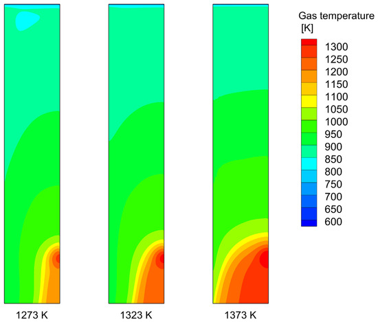
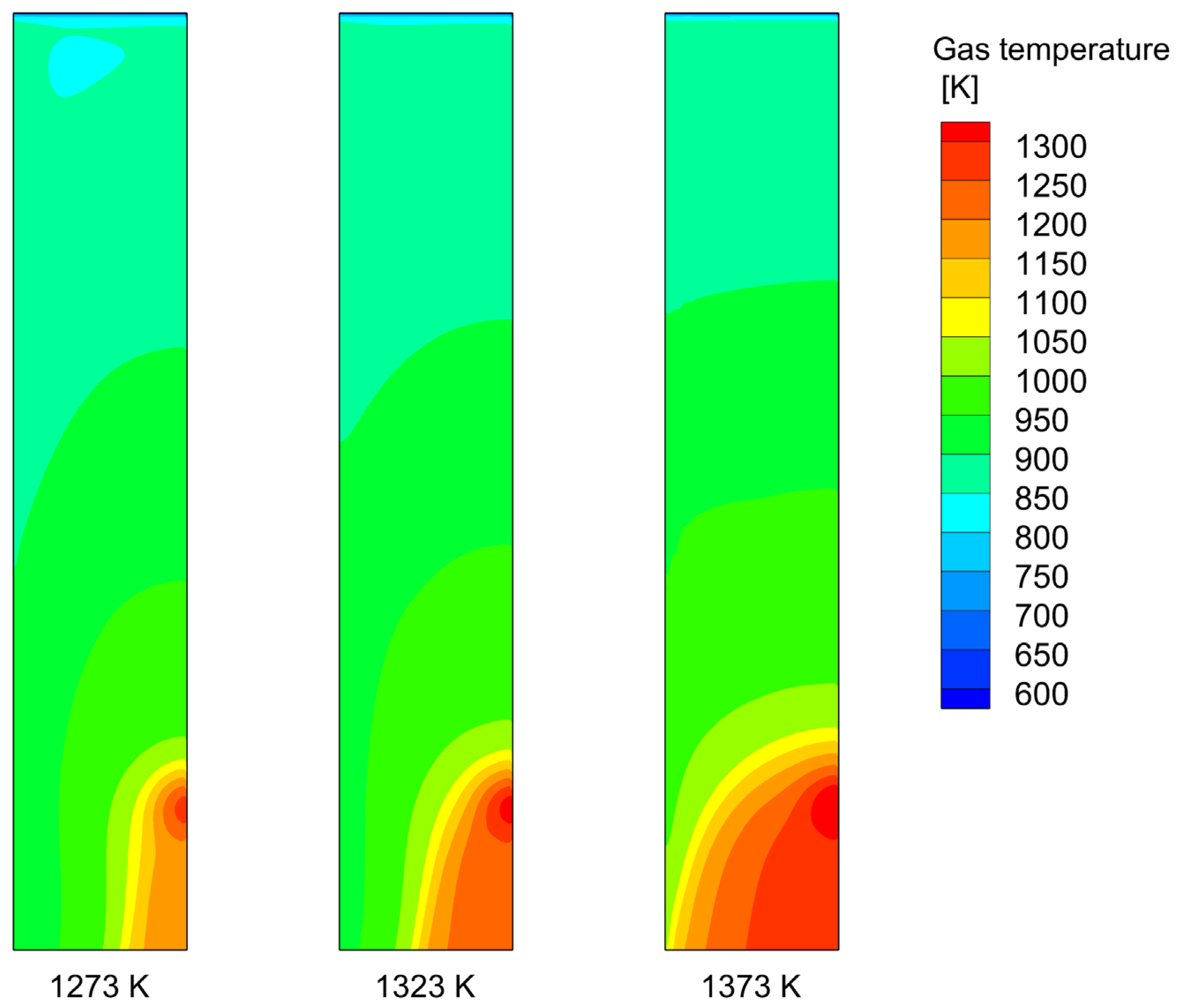
Figure 6 illustrates the gas temperature distributions under three different reducing gas feed temperatures. As the gas temperature increases from 1273 K to 1373 K, the temperature level in the shaft furnace progressively increases, particularly in the lower part of the reactive zone. In general, the improved thermal condition is beneficial for the endothermic reactions involving CH4 reforming, H2 reduction, and CH4 decomposition from both thermodynamic and kinetic points of view, suggesting improved performance in both metallization and carburization under higher gas feed temperatures.
Figure 6.
Gas temperature distributions under different reducing gas feed temperatures.
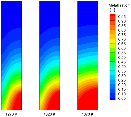
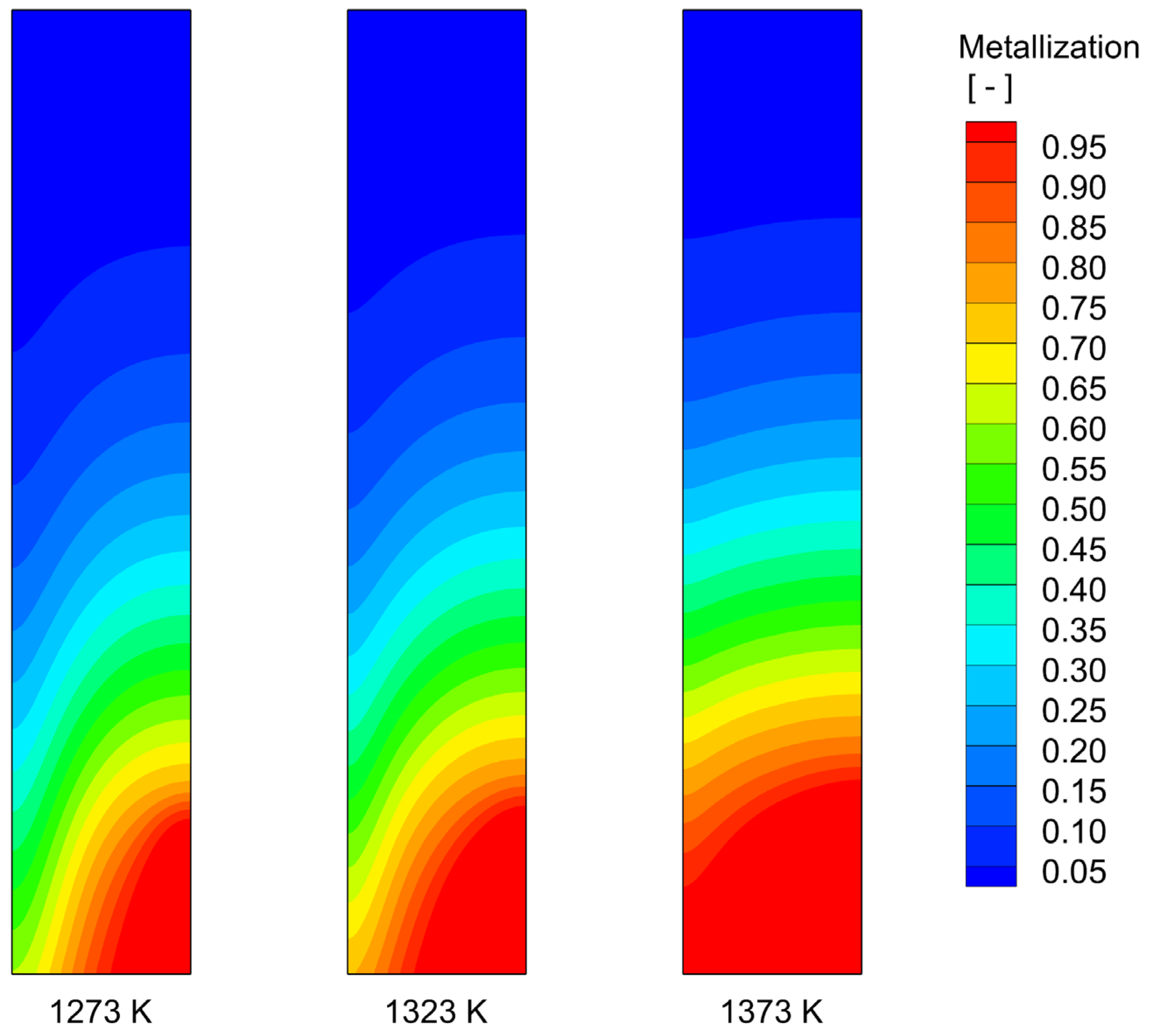
Figure 7 shows the distributions of the solid metallization degree in the furnace. As the reducing gas temperature increases from 1273 K to 1373 K, the high-metallization region expands progressively. This behavior is consistent with the thermal state shown in Figure 6. As a result, the outlet-averaged metallization degree increases from 0.9426 at 1273 K to 0.9797 at 1323 K, and finally reaches complete metallization at 1373 K, as listed in Table 5.
Figure 7.
Distributions of solid metallization degree under different reducing gas feed temperatures.
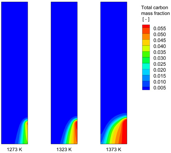
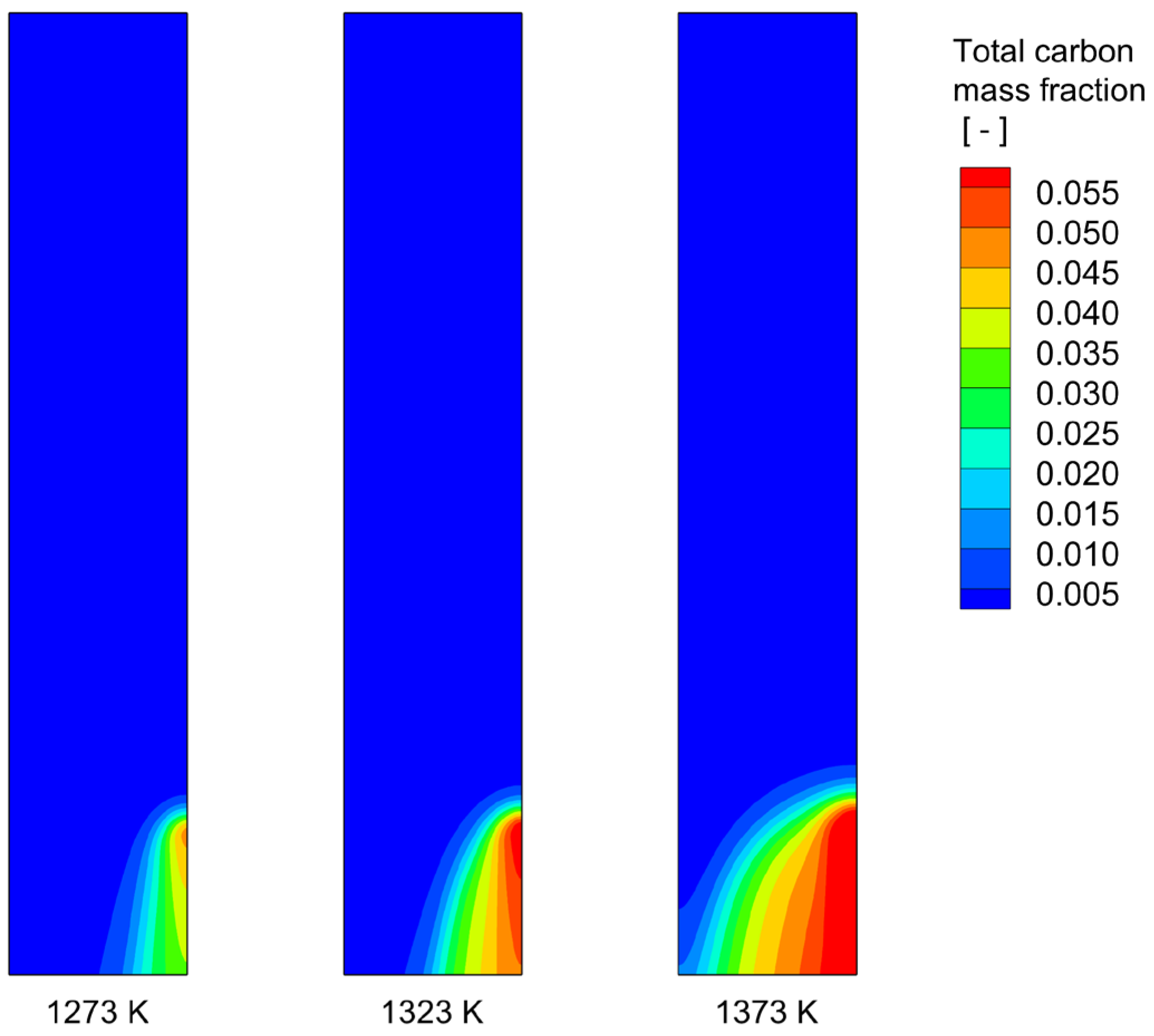
As for carburization, Figure 8 depicts the total carbon distributions under the three temperatures of 1273 K, 1323 K, and 1373 K. It is seen that the total carbon distribution is highly sensitive to the reducing gas feed temperature. With increasing temperature, the carbon-rich region near the lower shaft becomes progressively larger and extends further into the burden bed. This behavior is consistent with the temperature and metallization fields shown in Figure 6 and Figure 7, as carbon uptake is favored by both elevated temperature and the availability of metallic iron. Consequently, the outlet-averaged total carbon mass fraction rises significantly from 0.01722 at 1273 K to 0.03128 at 1323 K, and then to 0.04938 at 1373 K. These results confirm that increasing the reducing gas temperature is highly effective in strengthening the reduction and carburization performance of the ENERGIRON ZR shaft furnace.
Figure 8.
Distributions of total carbon mass fraction under different reducing gas feed temperatures.
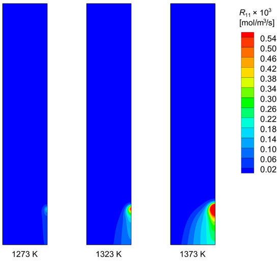
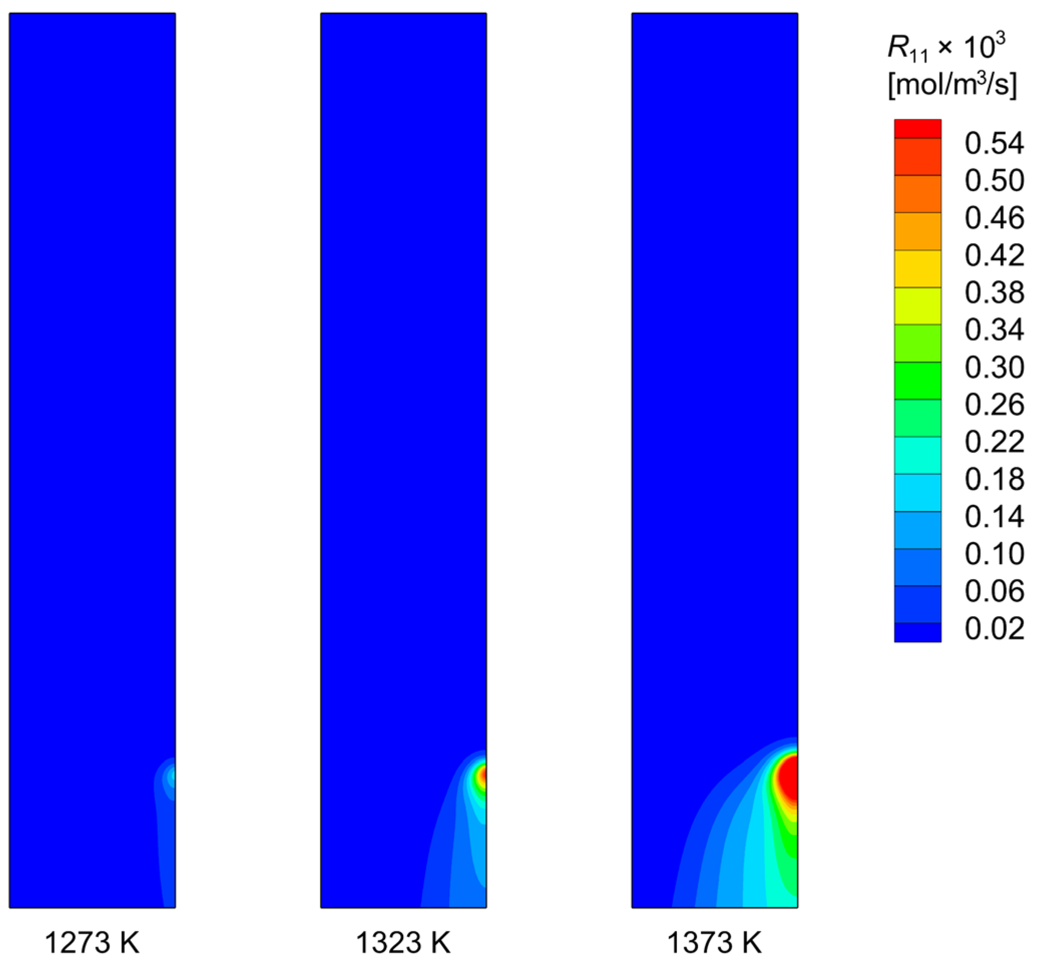
The corresponding distributions of the Fe3C decomposition rate (R11) are presented in Figure 9, where a clear temperature dependence can be observed. At 1273 K, R11 is very weak and only appears in a narrow local region near the gas inlet, indicating a highly limited formation of free carbon. As the reducing gas temperature increases, however, both the intensity and spatial extent of R11 increase progressively, suggesting that Fe3C decomposition becomes much stronger under higher temperature conditions. This behavior is consistent with the model formulation, in which the Fe3C decomposition rate is strongly promoted by increasing carbon diffusivity in the iron phase (cf. Equation (11)) at elevated temperatures. Overall, although higher temperatures promote total carbon uptake, they also favor the subsequent decomposition of Fe3C into free carbon. As a result, the rise in total carbon at higher temperatures is accompanied by a shift in carbon partitioning, with the fraction of combined carbon decreasing and that of free carbon increasing, as summarized in Table 5.
Figure 9.
Distributions of reaction rate of Fe3C decomposition (R11 of Table 1) under different reducing gas feed temperatures.
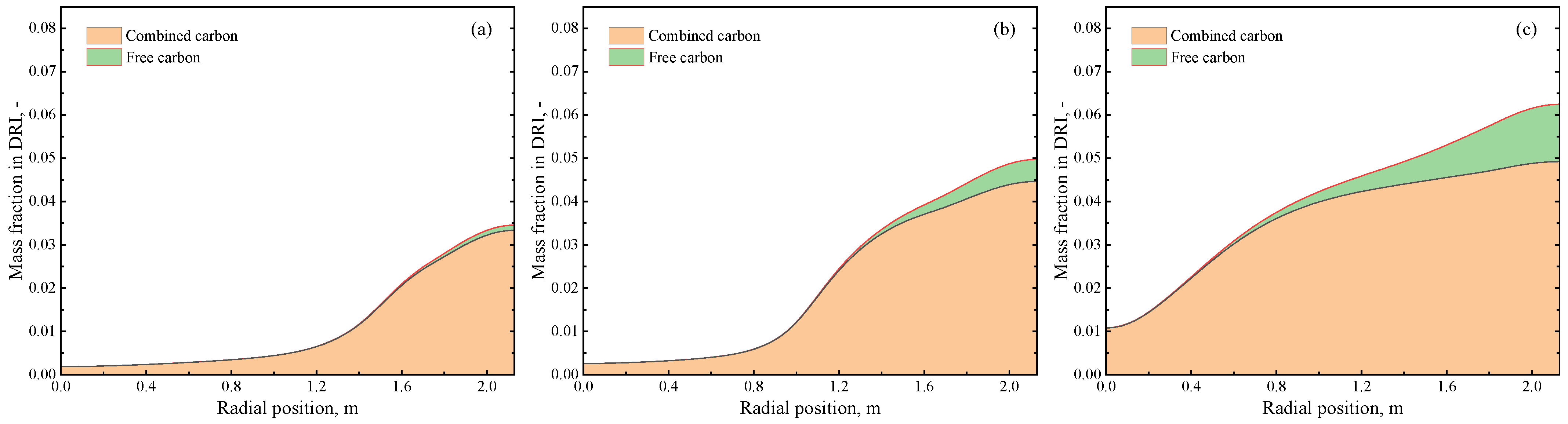
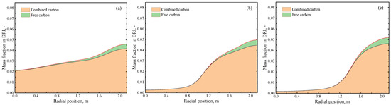
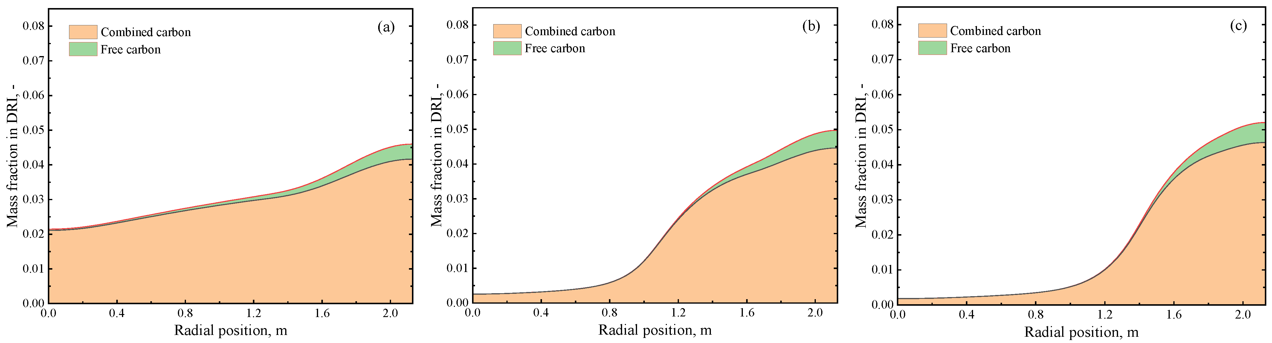
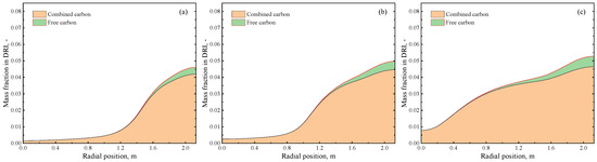
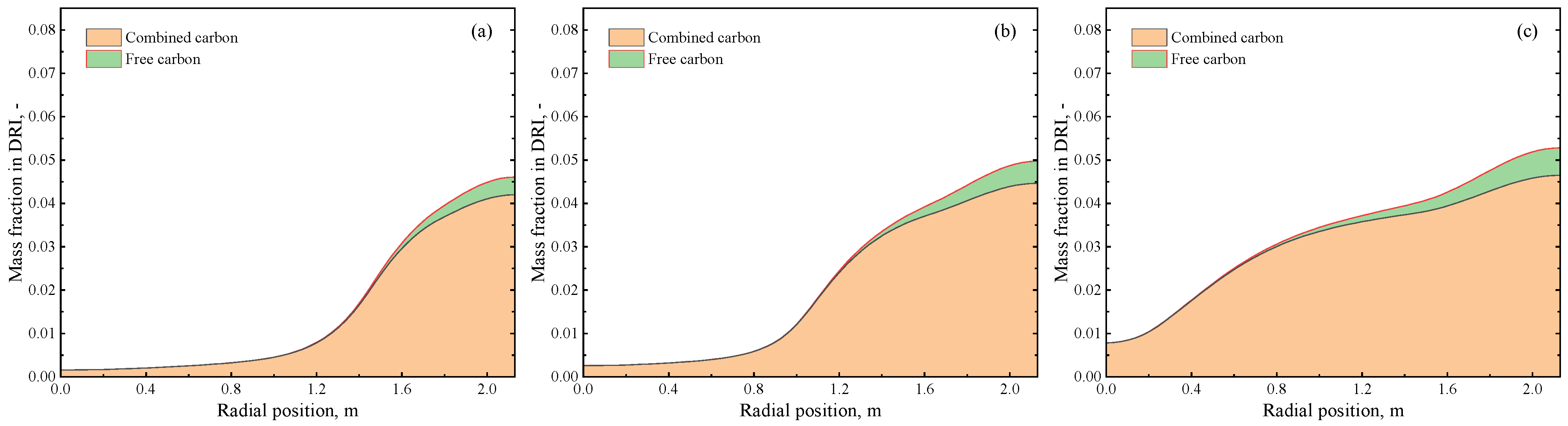
To shed more light on carbon partitioning in the final DRI product, Figure 10 shows the radial distributions of combined carbon and free carbon at the furnace bottom. In all three cases, pronounced radial non-uniformity is observed. To quantify the radial variation in the overall carburization level, a total carbon non-uniformity coefficient, UTC, is defined as
where , , and denote the maximum, minimum, and mass-weighted average total carbon mass fractions at the furnace outlet, respectively. According to this definition, a larger value of UTC indicates stronger non-uniformity in total carbon distribution. In addition, the radial non-uniformity of carbon partitioning is evaluated based on the variation in the combined carbon fraction from the furnace center to the near-wall region.
Figure 10.
Radial carbon distributions in DRI at the furnace bottom under different reducing gas feed temperatures: (a) 1273 K, (b) 1323 K, and (c) 1373 K.
The carbon content is generally lower in the central region and increases towards the wall side, which is consistent with the total carbon distribution results shown in Figure 8. At 1273 K (Figure 10a), the overall carbon level remains relatively low, and the deposited carbon is dominated by combined carbon, while the amount of free carbon is very limited across the whole radius. In this case, UTC is calculated to be 1.898, indicating a pronounced center-to-wall variation in the overall carburization level, while the combined carbon fraction decreases slightly from 99.9% at the center to 96.5% near the wall. This suggests that, under the lower gas feed temperature, carburization remains relatively weak and the decomposition of Fe3C is largely suppressed.
At 1323 K (Figure 10b), both the combined carbon and the total carbon level increase significantly over the entire radius, with the near-wall region exhibiting the highest carbon concentration. Meanwhile, free carbon becomes more pronounced than that at 1273 K, especially close to the wall, indicating that the enhancement of carburization is accompanied by stronger Fe3C decomposition. As a result, UTC decreases to 1.508, indicating improved radial uniformity of the total carbon distribution, while the combined carbon fraction declines more markedly, from 99.9% at the center to 89.8% near the wall.
At 1373 K (Figure 10c), the radial non-uniformity of carbon partitioning becomes even more evident. Although UTC further decreases to 1.046, indicating a more uniform radial distribution of the overall carbon content, the combined carbon fraction decreases markedly from 99.5% at the center to 78.8% near the wall, demonstrating substantial near-wall enrichment of free carbon. These results show that increasing the gas feed temperature not only enhances overall carburization and improves the radial uniformity of total carbon, but also promotes Fe3C decomposition, thereby shifting carbon partitioning towards free carbon in the most strongly carburized near-wall region. Therefore, a more uniform radial distribution of total carbon does not necessarily correspond to a more uniform distribution of carbon forms.
3.3. Effect of Reducing Gas Composition
In this subsection, the effect of reducing gas composition is clarified by comparing the results of Cases C1–C9 in Table 5, in which the CH4 content in the reducing gas is varied from 15% to 25% under three different gas feed temperatures, namely 1273 K, 1323 K, and 1373 K.
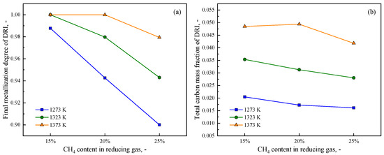
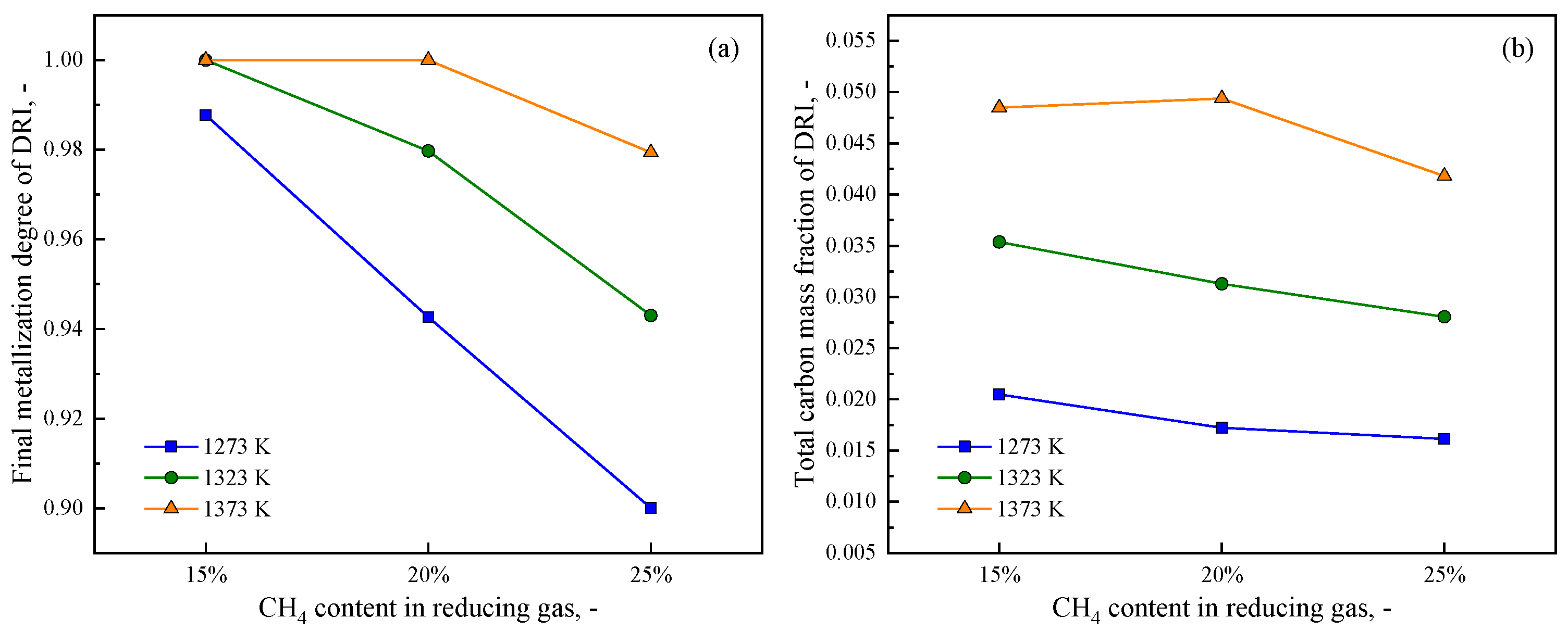
Figure 11 summarizes the effects of CH4 content in the reducing gas on the final metallization degree and the total carbon level of DRI under the above three gas feed temperatures. Although the corresponding values are already listed in Table 5, they are replotted here to more clearly illustrate the overall trends. It can be seen that the effect of CH4 content on metallization is generally consistent at different gas feed temperatures: increasing CH4 tends to deteriorate the final reduction performance. At both 1273 K and 1323 K, the outlet-averaged metallization degree decreases monotonically as the CH4 content increases from 15% to 25%. At 1373 K, although complete metallization is maintained at 15% and 20% CH4, a further increase to 25% CH4 still lowers the metallization degree.
Figure 11.
Effect of CH4 content in the reducing gas on (a) final metallization degree and (b) total carbon under different gas feed temperatures.
By contrast, the response of total carbon is temperature dependent. At 1273 K and 1323 K, the total carbon mass fraction decreases monotonically with increasing CH4 content, from 0.02048 to 0.01615 at 1273 K, and from 0.03536 to 0.02805 at 1323 K. However, at 1373 K, a different trend is observed: the total carbon first increases slightly from 0.04849 at 15% CH4 to 0.04938 at 20% CH4, and then decreases to 0.04179 at 25% CH4. To clarify the underlying mechanism, the following discussion first focuses on the representative cases at 1323 K and then returns to the 1373 K condition to explain the non-monotonic variation in total carbon.
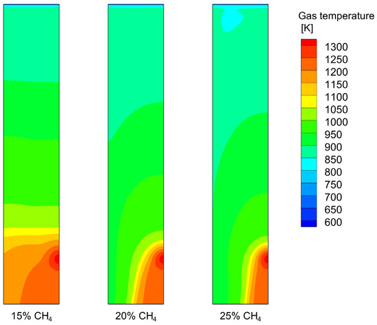
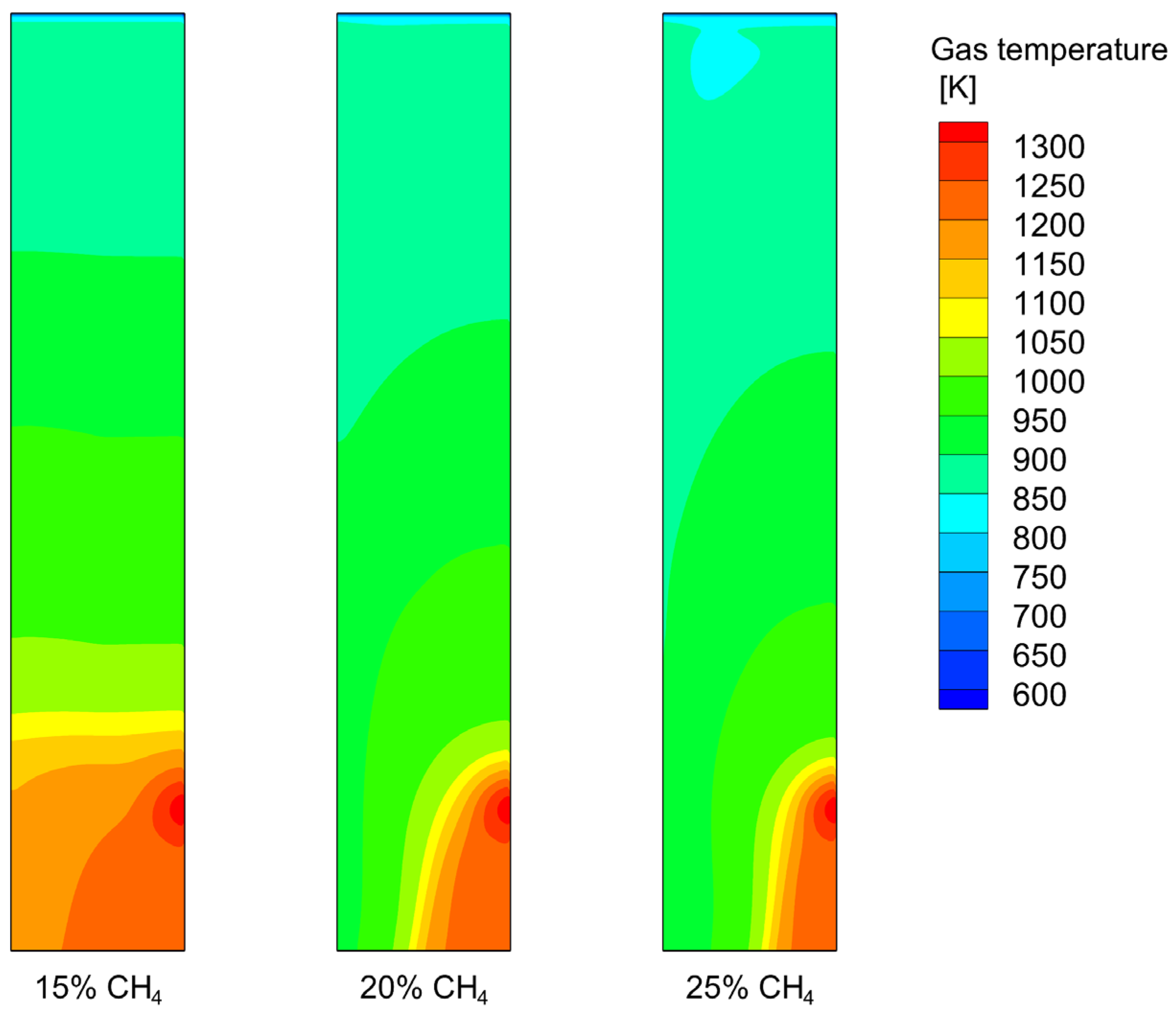
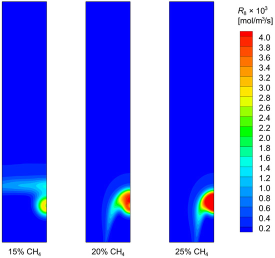
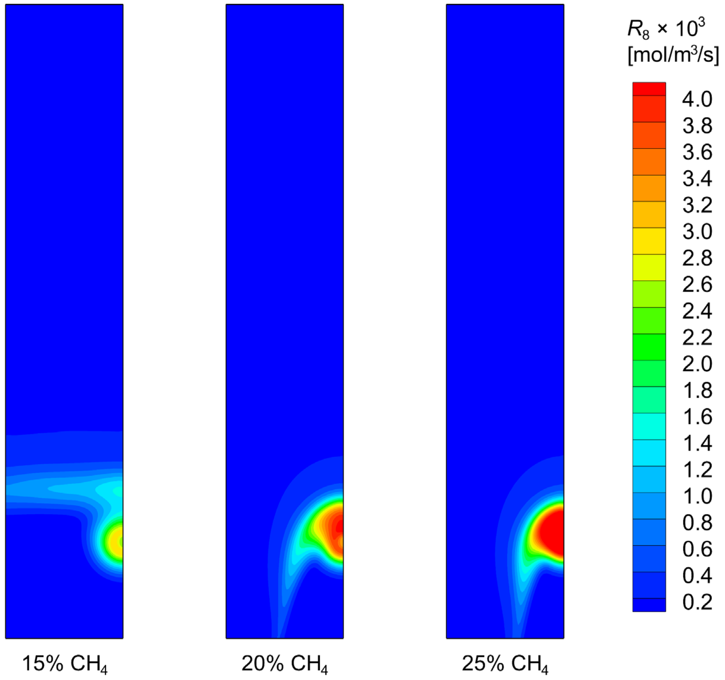
Figure 12 presents the gas temperature distributions at CH4 contents of 15%, 20%, and 25% under a gas feed temperature of 1323 K. A clear decline in the furnace thermal level can be observed as the CH4 content increases, since the high-temperature region at the lower part of the reactive zone shrinks continuously. This behavior can be attributed to the results shown in Figure 13, where the distributions of the CH4 reforming rate (R8) are illustrated. It can be seen that increasing the CH4 content clearly intensifies the reforming reaction in the lower region near the gas inlet, where high CH4 concentration, high temperature, and abundant metallic iron coexist. Since CH4 reforming is a strongly endothermic reaction, this intensification leads to greater local heat consumption and therefore lowers the thermal level within the furnace. As a result, the outlet-averaged metallization degree decreases from 1.0 at 15% CH4 to 0.9797 at 20% CH4 and further to 0.9430 at 25% CH4, since the lowered temperature level limits the reduction process, particularly the H2-based reduction.
Figure 12.
Gas temperature distributions under different CH4 contents in feed gas with a temperature of 1323 K.
Figure 13.
Distributions of reaction rate of CH4 reforming (R8 of Table 1) under different CH4 contents in feed gas with a temperature of 1323 K.
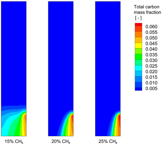
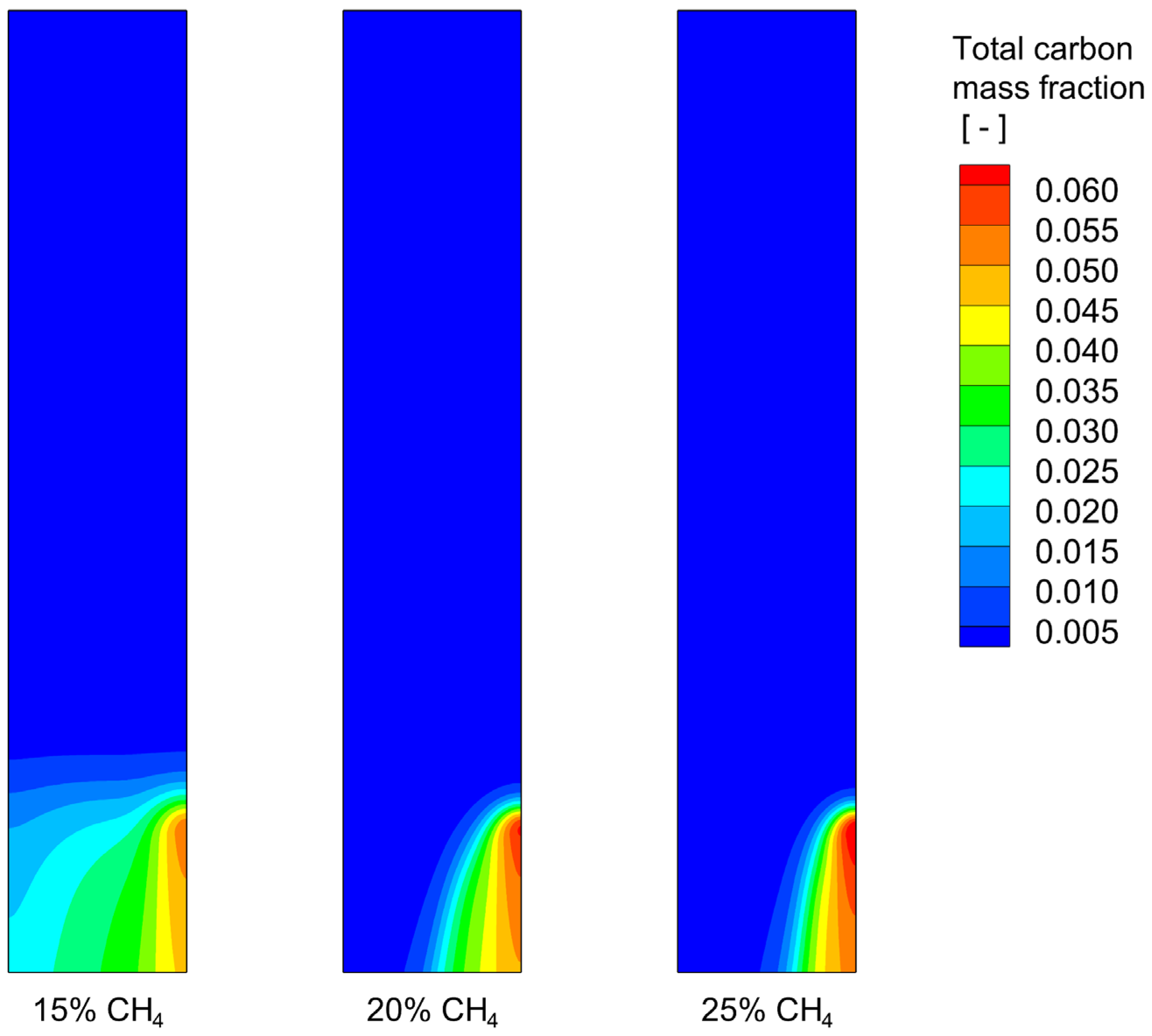
As for the effect of CH4 content on carburization, Figure 14 shows the corresponding distributions of total carbon mass fraction in the furnace. At 15% CH4, the carbon-enriched zone extends over a relatively wide area in the lower part of the reactive zone, indicating that carburization can proceed over a larger portion of the burden bed. As the CH4 content increases, it is observed that the spatial region with appreciable carbon content becomes progressively smaller, while the local carbon level near the wall becomes somewhat higher. However, this local increase is not sufficient to compensate for the simultaneous shrinkage of the overall carburized region. As a result, the outlet-averaged total carbon mass fraction decreases from 0.03536 at 15% CH4 to 0.03128 at 20% CH4, and further to 0.02805 at 25% CH4, as already summarized in Table 5 and Figure 11. To better understand this behavior, the radial carbon distributions at the furnace bottom are further examined in Figure 15. Under all three CH4 contents, the carbon distribution is clearly non-uniform in the radial direction, with a lower carbon level in the central region and a higher carbon level towards the furnace wall. At 15% CH4, the radial variation is relatively weak, and the combined carbon is distributed more uniformly across the furnace bottom, while the free carbon level remains relatively low throughout the radius. The corresponding value of UTC is 0.694, and the combined carbon fraction decreases from 98.3% at the center to 90.6% near the wall.
Figure 14.
Distributions of total carbon mass fraction under different CH4 contents in feed gas with a temperature of 1323 K.
Figure 15.
Radial carbon distributions in DRI at the furnace bottom under different CH4 contents in feed gas with a temperature of 1323 K: (a) 15%, (b) 20%, and (c) 25%.
As the CH4 content increases to 20% and further to 25%, the radial non-uniformity becomes more pronounced. In particular, the carbon level near the wall increases, whereas the carbon content in the central region decreases noticeably. As a result, UTC increases markedly to 1.508 at 20% CH4 and further to 1.793 at 25% CH4. Meanwhile, the increase in free carbon is also mainly concentrated in the near-wall region, where the combined carbon fraction decreases to 89.8% and to 89.0%, respectively. These results suggest that increasing the CH4 content does not enhance carburization uniformly across the entire outlet section; instead, it makes the carburization behavior more localized and radially non-uniform. Therefore, increasing the CH4 content intensifies not only the radial non-uniformity of the overall carbon level but also the near-wall enrichment of free carbon. Although the near-wall carbon enrichment becomes stronger at higher CH4 contents, the simultaneous decrease in carbon uptake in the central region leads to a lower outlet-averaged total carbon level overall.
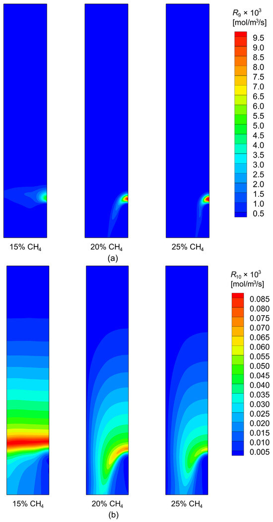
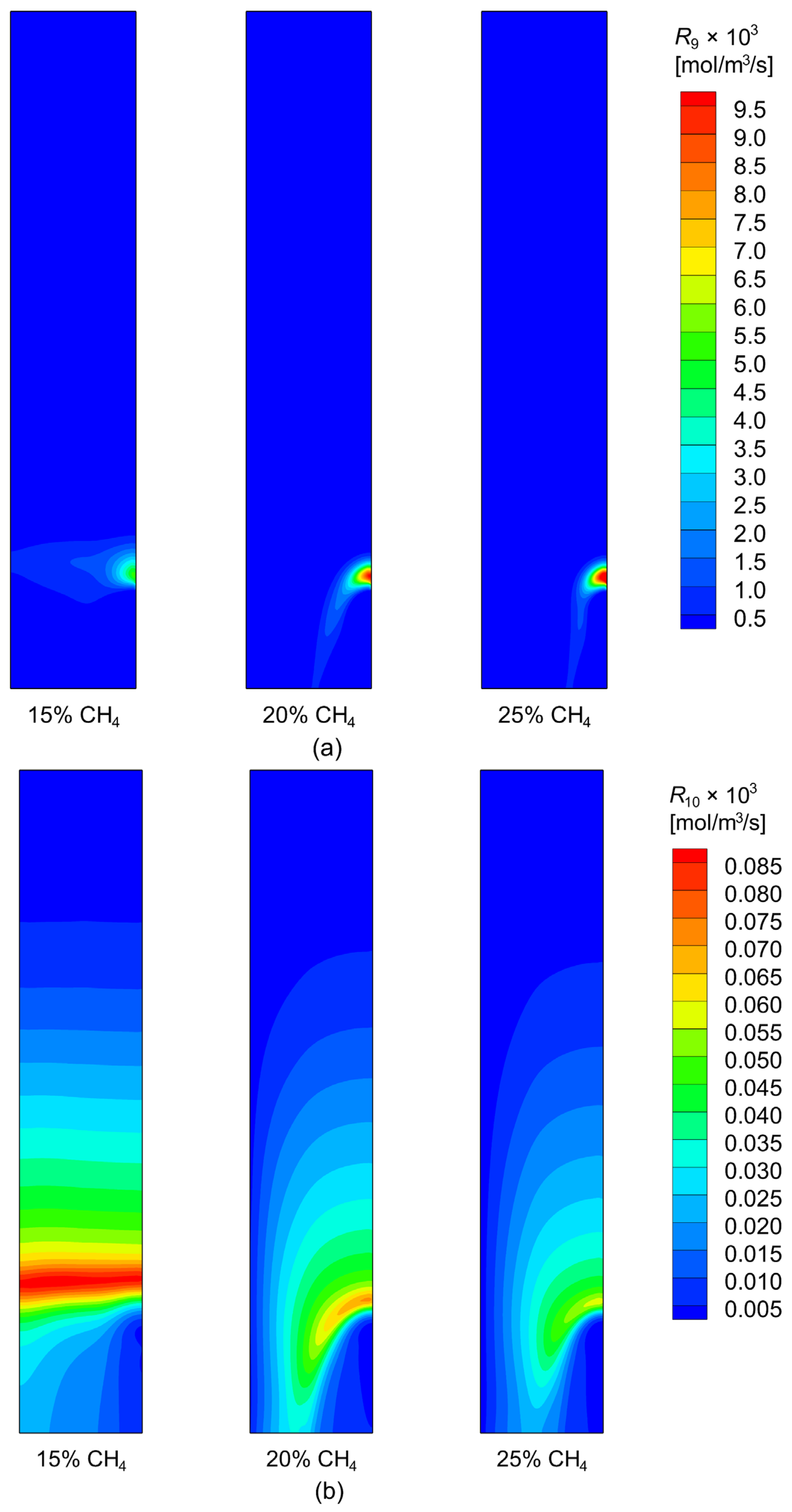
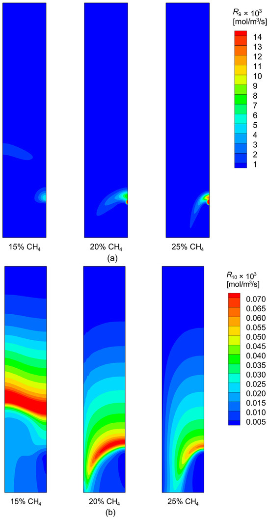
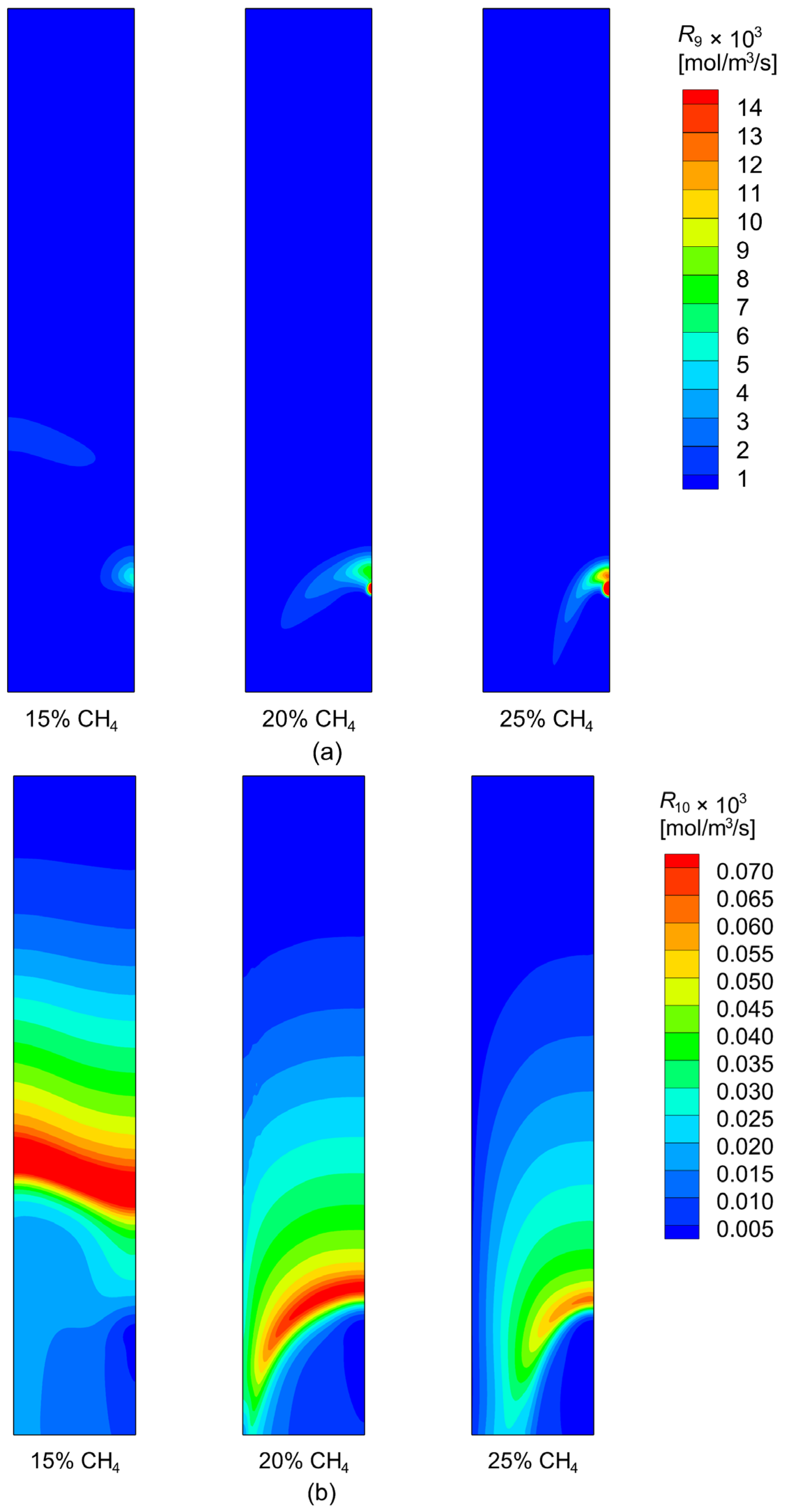
The origin of the increasing radial non-uniformity with CH4 content can be further understood from the carburization rate distributions shown in Figure 16. It is seen that the CH4-based carburization route, R9, becomes progressively stronger as the CH4 content increases from 15% to 25%, as shown in panel a, but this enhancement is increasingly concentrated in a narrow region near the gas inlet and close to the wall. By contrast, at 15% CH4, the CO-based carburization route, R10, is not only more intense than in the higher-CH4 cases, but also extends over a much broader region, as illustrated in panel b. This is related to the more favorable thermal condition (cf. Figure 12) and the higher metallization level at lower CH4 content. Integrated results show that at 15%, 20%, and 25% CH4, the CO-based route contributes to approximately 14.9%, 12.4%, and 11.4% of the total carbon uptake, respectively. Therefore, although increasing CH4 enhances the local intensity of R9, the simultaneous contraction of the R9-active region together with the weakening of the CO-based carburization reduces the overall carbon content in DRI.
Thus, under the present 1323 K condition, a seemingly contradictory result is obtained: increasing the CH4 content is expected to enhance carburization by raising the nominal carbon potential of the reducing gas, yet the overall carbon uptake actually decreases due to the heat shortage in the furnace caused by the intensified, strongly endothermic reforming reaction. This mechanism is also expected to hold for the 1273 K cases, where the sensible heat supply is even more limited, thereby explaining the similar variation trends of metallization degree and total carbon with CH4 content at these two temperatures.
However, when the gas feed temperature is further increased to 1373 K, the situation becomes different, as shown in Figure 17. Compared with the 20% CH4 case, the CH4-based carburization route, R9, is clearly weakened at 15% CH4, although the CO-based route, R10, remains noticeably stronger and more broadly distributed under the latter condition. This indicates that, under the higher-temperature condition of 1373 K, the furnace thermal level is already sufficiently high, and the limiting factor for carburization is no longer dominated by sensible heat alone. Instead, when the CH4 content is reduced to 15%, the CH4 supply itself becomes insufficient to sustain a higher overall carburization level. As a result, although the more favorable thermal condition and the stronger CO-based carburization at 15% CH4 are beneficial, they cannot fully compensate for the weaker CH4-based carburization, and the total carbon remains slightly lower than that at 20% CH4.
When the CH4 content is further increased from 20% to 25%, the dominant limitation shifts again. In this case, the additional CH4 intensifies the strongly endothermic reforming reaction and causes a deterioration in the furnace thermal level, as already discussed for the 1323 K cases. Consequently, the total carbon decreases from 0.04938 at 20% CH4 to 0.04179 at 25% CH4. Therefore, the results at 1373 K suggest that the controlling factor for carburization changes with CH4 content: at 15% CH4, CH4 availability becomes insufficient, whereas at 25% CH4, the thermal shortage associated with excessive reforming becomes dominant. The 20% CH4 case thus represents a balance between these two competing effects and yields the highest total carbon under the present high-temperature condition.
3.4. Effect of Reducing Gas Feed Rate
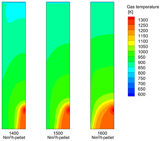
In this subsection, the effect of reducing gas feed rate is clarified by comparing Cases F1–F3 in Table 5, in which the gas feed rate is varied from 1400 to 1600 Nm3/t-pellet while the gas composition and feed temperature are kept the same as those of the base case.
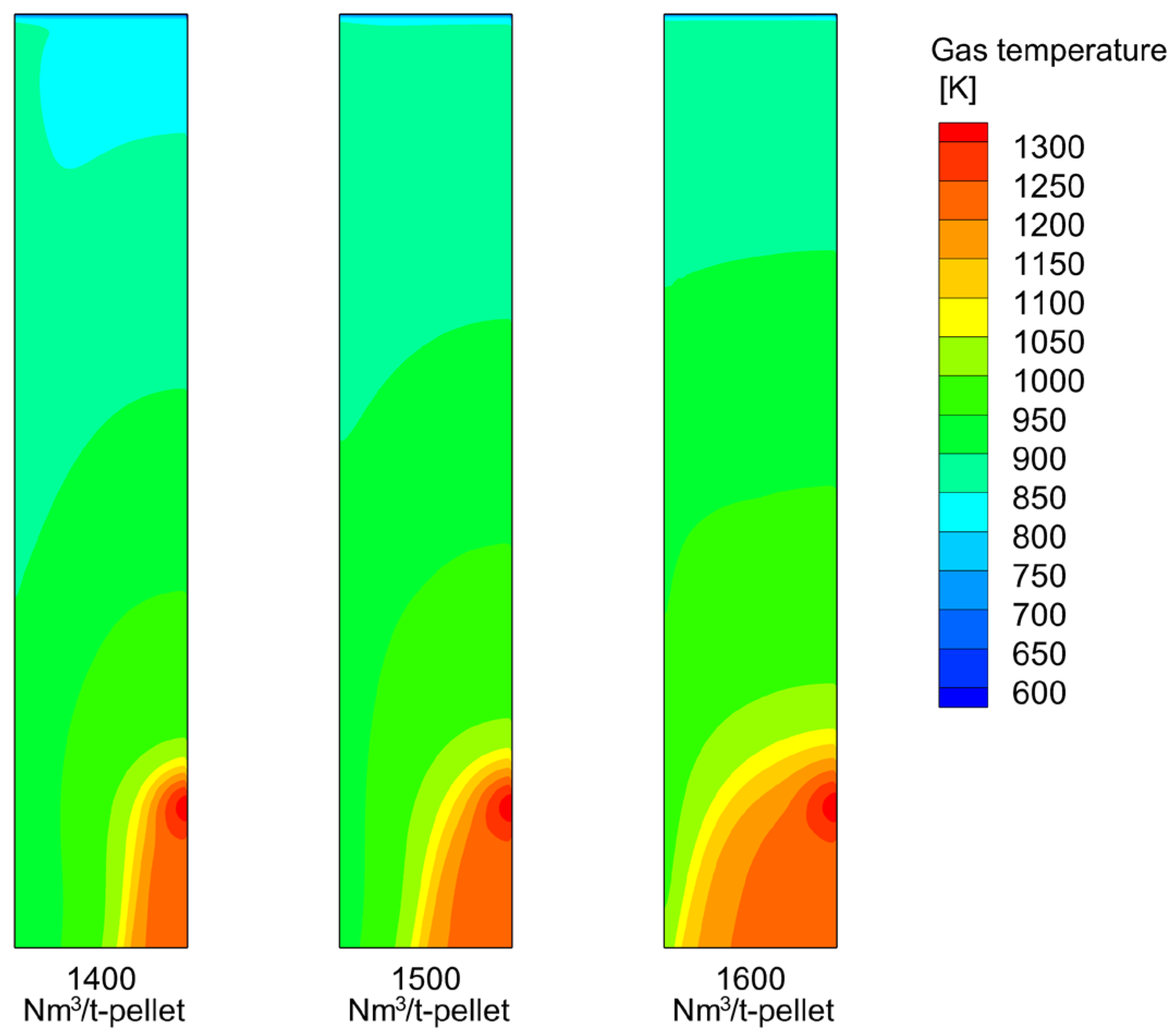
Figure 18 shows the gas temperature distributions under three different reducing gas feed rates. As the feed rate increases, the thermal level in the shaft furnace is clearly enhanced, particularly in the lower part of the reactive zone as the high-temperature region (red zone) becomes progressively larger and extends further inward into the burden bed. The increased amounts of reducing gas and sensible heat indicate an improved thermochemical condition for both reduction and carburization.
Figure 18.
Gas temperature distributions under different gas feed rates.
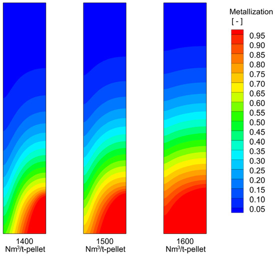
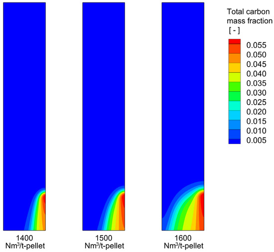
Figure 19 presents the corresponding metallization distributions. As expected, the high-metallization region expands progressively upward and inward with increasing gas feed rate. As a result, the outlet-averaged metallization degree rises from 0.9339 at 1400 Nm3/t-pellet to 0.9797 at 1500 Nm3/t-pellet, and finally reaches complete metallization at 1600 Nm3/t-pellet. The corresponding effect on carburization is reflected in Figure 20, which shows the distributions of total carbon mass fraction under different reducing gas feed rates. It is observed that a higher gas feed rate not only intensifies local carburization, but also enlarges the spatial region in which carbon uptake can proceed effectively. Consequently, the outlet-averaged total carbon mass fraction increases from 0.02360 at 1400 Nm3/t-pellet to 0.03128 at 1500 Nm3/t-pellet, and further to 0.04047 at 1600 Nm3/t-pellet. These results confirm that increasing the reducing gas feed rate is highly beneficial for both reduction and carburization performance.
Figure 19.
Distributions of solid metallization degree under different gas feed rates.
Figure 20.
Distributions of total carbon mass fraction under different gas feed rates.
Further insight into the outlet carbon state can be obtained from the radial carbon distributions at the furnace bottom, as shown in Figure 21. Under all three feed rates, the carbon distribution remains radially non-uniform, showing a consistently increasing carbon level from the central region towards the furnace wall. As the reducing gas feed rate increases from 1400 to 1600 Nm3/t-pellet, the carbon level is elevated over almost the entire outlet section. Quantitatively, UTC decreases from 1.886 at 1400 Nm3/t-pellet to 1.508 at 1500 Nm3/t-pellet and further to 1.110 at 1600 Nm3/t-pellet. This decrease demonstrates that increasing the gas feed rate improves the radial uniformity of the overall carburization level by promoting carbon uptake in the central region.
Figure 21.
Radial carbon distributions in DRI at the furnace bottom under different gas feed rates: (a) 1400 Nm3/t-pellet, (b) 1500 Nm3/t-pellet, and (c) 1600 Nm3/t-pellet.
At the same time, the near-wall region still exhibits the strongest carbon enrichment. The combined carbon fraction near the wall decreases from 91.1% at 1400 Nm3/t-pellet to 89.8% at 1500 Nm3/t-pellet and further to 88.0% at 1600 Nm3/t-pellet, indicating a gradual increase in the local free carbon fraction at higher feed rates. However, the outlet-averaged combined carbon fraction decreases only slightly, from 93.9% to 92.5%. Therefore, increasing the reducing gas feed rate enhances carbon uptake over a broad portion of the outlet section and improves the radial uniformity of total carbon, while Fe3C remains the dominant carbon-bearing phase in the final DRI.
3.5. Comparison with Industrial Carbon Partitioning Trend
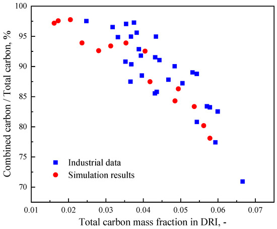
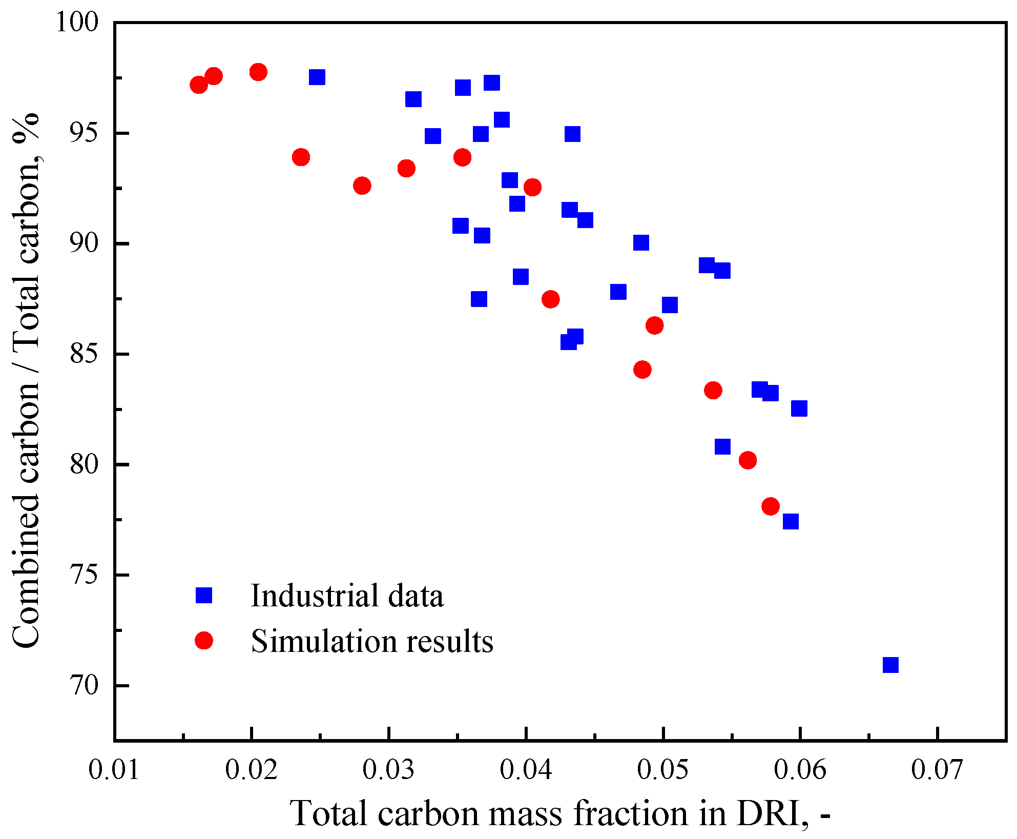
To further evaluate the industrial relevance of the present model, the predicted carbon partitioning in DRI is compared with the reported industrial data in Figure 22. The industrial data were digitized from the published graph in Ref. [14] and replotted by the present authors. The simulation results are represented by the outlet-section-averaged values of the cases listed in Table 5, including three additional high-carbon cases introduced to extend the predicted carbon range. It can be seen that the simulation results essentially show qualitative agreement with the industrial data: as the total carbon level in DRI increases, the fraction of combined carbon decreases progressively, indicating a corresponding increase in the proportion of free carbon. This agreement confirms that the present model captures the essential relationship between the overall carburization level and carbon partitioning in industrial shaft furnace operation. Combined with the preceding analyses, these results suggest that beneficial carburization in the ENERGIRON ZR shaft furnace requires a balance among CH4 availability, furnace thermal level, and gas throughput: insufficient thermal support suppresses overall carburization, whereas excessively strong carburization conditions promote the decomposition of Fe3C and the formation of free carbon.
Figure 22.
Comparison of carbon partitioning in DRI between industrial data [14] and simulation results.
4. Conclusions and Future Prospects
In this work, a two-dimensional computational fluid dynamics (CFD) model was developed for the reactive zone of an industrial-scale shaft furnace operated under ENERGIRON ZR (zero-reforming) conditions, in which carbon in direct reduced iron (DRI) was explicitly distinguished into combined carbon in Fe3C and free carbon in graphitic form. Based on the model validation against available plant data, the effects of reducing gas temperature, gas composition, and gas feed rate on reduction, carburization, and carbon partitioning were systematically investigated. The main conclusions are summarized as follows.
- Under the baseline ENERGIRON ZR condition, in situ reforming, iron oxide reduction, and carburization are strongly coupled in the lower part of the reactive zone near the gas inlet. CH4 reforming generates additional H2 and CO to sustain reduction, while carburization mainly occurs after sufficient metallic iron has been formed. The predicted carbon in DRI is dominated by Fe3C, whereas graphitic carbon appears only in a relatively limited local region.
- Increasing the reducing gas feed temperature from 1273 K to 1373 K increases the outlet-averaged metallization degree from 0.9426 to 1.000 and the total carbon mass fraction from 0.01722 to 0.04938. However, a higher temperature also promotes Fe3C decomposition, reducing the combined carbon fraction from 97.6% to 86.3%. Meanwhile, the total carbon non-uniformity coefficient, UTC, decreases from 1.898 to 1.046, indicating that the radial distribution of total carbon becomes more uniform, although the center-to-wall variation in carbon partitioning becomes more pronounced.
- The effect of CH4 content on carburization is temperature dependent. At 1273 K and 1323 K, increasing the CH4 content from 15% to 25% leads to decreases in both metallization degree and total carbon content, due to the deteriorated in-furnace thermal level caused mainly by the intensified endothermic reforming reaction. By contrast, at 1373 K, the total carbon first increases slightly from 15% CH4 to 20% CH4, and then decreases at 25% CH4. The results suggest that at 15% CH4, methane availability becomes insufficient to sustain a higher overall carburization level, whereas at 25% CH4, the thermal shortage caused by excessive reforming becomes dominant. In addition, under a temperature of 1323 K, UTC increases from 0.694 at 15% CH4 to 1.793 at 25% CH4, demonstrating that a higher CH4 content intensifies the radial non-uniformity of carburization.
- Increasing the reducing gas feed rate from 1400 Nm3/t-pellet to 1600 Nm3/t-pellet enhances the thermal level, and thus increases the overall metallization degree from 0.9339 to 1.000 and total carbon mass fraction from 0.02360 to 0.04047. Meanwhile, UTC decreases from 1.886 to 1.110, showing that the radial distribution of total carbon becomes more uniform. In addition, the outlet-averaged combined carbon fraction decreases slightly from 93.9% to 92.5%, confirming that Fe3C remains the predominant carbon-bearing phase in the final DRI. Therefore, increasing the gas feed rate is an effective way to strengthen both reduction and overall carburization while maintaining a high combined carbon fraction.
- Comparison with the limited industrial carbon partitioning data shows that the model predictions capture the qualitative trend of a decreasing combined carbon fraction with increasing total carbon content in DRI. However, because direct industrial measurements distinguishing Fe3C and graphitic carbon under known operating conditions are unavailable, this comparison should be interpreted as trend-level support rather than quantitative validation of the predicted carbon partitioning.
As for future work, several aspects deserve further investigation. First, the present model is restricted to the upper reactive zone of the shaft furnace; extension to the full furnace domain would allow the influence of the lower zones to be assessed more comprehensively. Second, the direct formation of graphitic carbon through methane decomposition and carbon monoxide precipitation was not explicitly modeled in the current work, and its incorporation may further improve the description of carbon form evolution under highly carburizing conditions. Moreover, a systematic thermodynamic assessment of the competition between methane availability and the thermal demand of reforming under different temperatures, pressures, and gas compositions will also be considered in future work. Finally, further validation against plant data for ENERGIRON ZR furnaces, especially data on carbon partitioning between Fe3C and graphitic carbon, together with sensitivity or uncertainty analysis regarding model inputs and kinetic parameters, would be highly valuable for strengthening the industrial applicability of the model.
Author Contributions
Conceptualization, L.S.; methodology, Y.Z.; software, Y.Z.; validation, Y.Z.; formal analysis, Y.Z.; investigation, Y.Z.; data curation, Y.Z.; writing—original draft preparation, Y.Z.; writing—review and editing, L.S. and H.S.; visualization, Y.Z.; supervision, L.S. and H.S.; project administration, L.S. and H.S.; funding acquisition, L.S. and H.S. All authors have read and agreed to the published version of the manuscript.
Funding
This research was financially supported by Business Finland and companies participating in the Towards Fossil-free Steel 2 project [grant no. 5561/31/2023], as well as by the Research Council of Finland in the IRONH2 project [grant no. 356878]. The study was also funded by the National Natural Science Foundation of China [grant no. 52374329].
Data Availability Statement
The raw data supporting the conclusions of this article will be made available by the authors on request.
Conflicts of Interest
The authors declare no conflicts of interest.
References
- Kim, J.; Sovacool, B.K.; Bazilian, M.; Griffiths, S.; Lee, J.; Yang, M.; Lee, J. Decarbonizing the iron and steel industry: A systematic review of sociotechnical systems, technological innovations, and policy options. Energy Res. Soc. Sci. 2022, 89, 102565. [Google Scholar] [CrossRef] [Scilit]
- Holappa, L. A general vision for reduction of energy consumption and CO2 emissions from the steel industry. Metals 2020, 10, 1117. [Google Scholar] [CrossRef] [Scilit]
- Fan, Z.; Friedmann, S.J. Low-carbon production of iron and steel: Technology options, economic assessment, and policy. Joule 2021, 5, 829–862. [Google Scholar] [CrossRef] [Scilit]
- Rosner, F.; Papadias, D.; Brooks, K.; Yoro, K.; Ahluwalia, R.; Autrey, T.; Breunig, H. Green steel: Design and cost analysis of hydrogen-based direct iron reduction. Energy Environ. Sci. 2023, 16, 4121–4134. [Google Scholar] [CrossRef] [Scilit]
- Ling, J.; Yang, H.; Tian, G.; Chen, J.; Wang, X.; Yu, X. Direct reduction of iron to facilitate net zero emissions in the steel industry: A review of research progress at different scales. J. Clean. Prod. 2024, 441, 140933. [Google Scholar] [CrossRef] [Scilit]
- Fueling the Future of Ironmaking: MIDREX FlexTM. Available online: https://www.midrex.com/tech-article/fueling-the-future-of-ironmaking-midrex-flex (accessed on 17 May 2026).
- Hydrogen-Based Steelmaking. Available online: https://www.millennium-steel.com/hydrogen-based-steelmaking (accessed on 17 May 2026).
- Kieush, L.; Lesiak, S.; Rieger, J.; Leitner, M.; Schmidt, L.; Daghagheleh, O. Reoxidation behavior of the direct reduced iron and hot briquetted iron during handling and their integration into electric arc furnace steelmaking: A review. Metals 2024, 14, 873. [Google Scholar] [CrossRef] [Scilit]
- Yang, L.; Feng, Z.; Hu, H.; Wei, G.; Xue, B.; Guo, Y.; Jiang, T. A review on production and application of direct reduced iron in gas-based shaft furnace-electric arc furnace route. J. Iron Steel Res. Int. 2025, 32, 485–518. [Google Scholar] [CrossRef] [Scilit]
- MIDREX. Available online: https://www.midrex.com/tech-article/increasing-carbon-flexibility-in-midrex-dri-products-adjustable-to-4-5-excellent-temperature-retention-with-midrex-act (accessed on 17 May 2026).
- Lüngen, H.B.; Schmöle, I.P. History, developments and processes of direct reduction of iron ores. In Proceedings of the 8th European Coke and Ironmaking Congress and the 9th International Conference on Science and Technology of Ironmaking, Bremen, Germany, 29 August–2 September 2022. [Google Scholar]
- Experience and Developments of the ENERGIRON DR Technology for H2 Use. Available online: https://www.energiron.com/sites/default/files/documents/2020_11-Experience%20and%20Developments%20of%20the%20ENERGIRON%20DR%20Technology%20for%20H2%20Use.pdf (accessed on 17 May 2026).
- Duarte, P.; Tavano, A.; Zendejas, E. Achieving carbon-free emissions via the ENERGIRON DR process. In Proceedings of the AISTech 2010—The Iron & Steel Technology Conference, Pittsburgh, PA, USA, 3–6 May 2010. [Google Scholar]
- Premium Quality DRI Products from ENERGIRON. Available online: https://www.energiron.com/sites/default/files/documents/Premium-Quality-DRI-Products-from-ENERGIRON.pdf (accessed on 17 May 2026).
- Memoli, F. Behavior and benefits of high-Fe3C DRI in the EAF. In Proceedings of the Association for Iron and Steel Technology Conference and Exposition (AISTech 2015), Cleveland, OH, USA, 4–7 May 2015. [Google Scholar]
- Béchara, R.; Hamadeh, H.; Mirgaux, O.; Patisson, F. Carbon impact mitigation of the iron ore direct reduction process through computer-aided optimization and design changes. Metals 2020, 10, 367. [Google Scholar] [CrossRef] [Scilit]
- Liu, Z.; Lu, S.; Wang, Y.; Zhang, J.; Cheng, Q.; Song, X. Optimization of hydrogen-based shaft furnace raw material parameters based on numerical simulation and Rist operation diagram. Metall. Mater. Trans. B 2023, 54, 2121–2136. [Google Scholar] [CrossRef] [Scilit]
- Liu, Z.; Lu, S.; Wang, Y.; Zhang, J.; Cheng, Q.; Ma, Y. Study on optimization of reduction temperature of hydrogen-based shaft furnace—Numerical simulation and multi-criteria evaluation. Int. J. Hydrogen Energy 2023, 48, 16132–16142. [Google Scholar]
- Tian, X.; Zhou, H.; Zhang, Y.; Zhang, T.; Huang, J.; Cai, H.; Kou, M.; Wu, S. Numerical simulation of the influence of operating parameters on the inner characteristics in a hydrogen-enriched shaft furnace. Int. J. Hydrogen Energy 2023, 55, 1131–1142. [Google Scholar] [CrossRef] [Scilit]
- Blahatia, K.; Veeramani, V.; Rajendran, V.; Pasupalak, M.; Sah, R. A CFD model of COREX gas-based DRI furnace for optimum gas consumption. Metall. Mater. Trans. B 2024, 55, 3961–3974. [Google Scholar] [CrossRef] [Scilit]
- Hosseinzadeh, M.; Kasiri, N.; Rezaei, M. Multiscale modeling of counter-current moving bed reactor for direct reduction of iron oxide: Unveiling influence of solid shape and pressure. Int. J. Hydrogen Energy 2024, 61, 1079–1091. [Google Scholar] [CrossRef] [Scilit]
- Immonen, J.; Powell, K.M. Dynamic modeling of a direct reduced iron shaft furnace to enable pathways towards decarbonized steel production. Chem. Eng. Sci. 2024, 300, 120637. [Google Scholar] [CrossRef] [Scilit]
- Shao, L.; Zhang, X.; Zhao, C.; Zhai, Y.; Saxén, H.; Zou, Z. A study of options to enhance the operation of a H2 direct reduction shaft furnace using a two-dimensional model. Int. J. Hydrogen Energy 2024, 86, 124–131. [Google Scholar] [CrossRef] [Scilit]
- Shao, L.; Zhao, C.; Zhai, Y.; Saxén, H.; Zou, Z. Numerical investigation on hydrogen reduction of iron oxide pellets in a shaft furnace: Unveiling the impact of particle size. Renew. Energy 2024, 237, 121743. [Google Scholar] [CrossRef] [Scilit]
- Zhai, Y.; Shao, L.; Zhao, C.; Zhang, X.; Saxén, H. A numerical study of the thermochemical and aerodynamic states of H2-intensive direct reduction shaft furnace. Steel Res. Int. 2025, 96, 2400567. [Google Scholar]
- Liu, Z.; Lu, S.; Wang, Y.; Zhang, J.; Li, J.; Cheng, Q. A numerical study on the production status changes of hydrogen-based shaft furnace during H2 replacement of coke oven gas. Steel Res. Int. 2025; early view.
- Xing, Y.; Luo, Z.; Li, H.; Wang, X.; Kou, M.; Wu, S.; Zou, Z.; Zhou, H. Modelling in-furnace phenomena in a hydrogen-rich low-carbon reduction smelting furnace: Influence of blast parameters of hydrogen-rich gas. Appl. Therm. Eng. 2025, 273, 126494. [Google Scholar]
- Zhao, C.; Shao, L.; Saxén, H. A comparative study on hydrogen reduction of iron oxide pellets in a shaft furnace with selective gas recycling. Steel Res. Int. 2025; early view. [CrossRef] [Scilit]
- Zhao, C.; Zhai, Y.; Shao, L.; Saxén, H. A numerical study on carburization enhancement of direct reduced iron in a hydrogen-intensive shaft furnace. Steel Res. Int. 2026; early view.
- Li, Z.; Qi, Z.; Zhang, L.; Guo, M.; Liang, D.; Dong, Q. Numerical simulation of H2-intensive shaft furnace direct reduction process. J. Clean. Prod. 2023, 409, 137059. [Google Scholar] [CrossRef] [Scilit]
- Alamsari, B.; Torii, S.; Trianto, A.; Bindar, Y. Study of the effect of reduced iron temperature rising on total carbon formation in iron reactor isobaric and cooling zone. Adv. Mech. Eng. 2010, 2, 192430. [Google Scholar] [CrossRef] [Scilit]
- Ajbar, A.; Alhumaizi, K.; Soliman, M. Modelling and parametric studies of direct reduction reactor. Ironmak. Steelmak. 2011, 38, 401–411. [Google Scholar] [CrossRef] [Scilit]
- Alhumaizi, K.; Ajbar, A.; Soliman, M. Modelling the complex interactions between reformer and reduction furnace in a MIDREX-based iron plant. Can. J. Chem. Eng. 2012, 90, 1120–1141. [Google Scholar]
- Shams, A.; Moazeni, F. Modeling and simulation of the MIDREX shaft furnace: Reduction, transition and cooling zones. JOM 2015, 67, 2681–2689. [Google Scholar] [CrossRef] [Scilit]
- Hamadeh, H.; Mirgaux, O.; Patisson, F. Detailed modeling of the direct reduction of iron ore in a shaft furnace. Materials 2018, 11, 1865. [Google Scholar] [CrossRef] [Scilit] [PubMed]
- Lu, S.; Liu, Z.; Wang, Y.; Zhang, J. Towards green steel—Energy and CO2 assessment of low carbon steelmaking via hydrogen based shaft furnace direct reduction process. Energy 2024, 309, 133080. [Google Scholar] [CrossRef] [Scilit]
- Fei, Y.; Kuang, S.; Guan, X.; Yu, A.; Evans, T.; Song, S.; Yang, N. Modeling industrial shaft furnaces and investigation of CH4-related side reactions. Appl. Therm. Eng. 2025, 282, 128835. [Google Scholar] [CrossRef] [Scilit]
- Lu, S.; Liu, Z.; Wang, Y.; Zhang, J.; Cheng, Q. Numerical simulation and multi-criteria evaluation of hydrogen-enriched shaft furnace with multiple gas sources. Fuel 2025, 383, 133929. [Google Scholar]
- Zhai, Y.; Zhao, C.; Shao, L.; Saxén, H. A numerical study of options for improving carburization in a hydrogen-intensive direct reduction shaft furnace. Metall. Mater. Trans. B 2025, 56, 6967–6982. [Google Scholar] [CrossRef] [Scilit]
- Hong, R.; Yu, X.; Shen, Y. An improved CFD study of direct reduction shaft furnace for low-carbon ironmaking. Chem. Eng. Sci. 2026, 325, 123463. [Google Scholar] [CrossRef] [Scilit]
- Kumar, N.; Van Ende, M.A.; Jung, I.H. An integrated two-scale numerical model for the direct reduction (DR) shaft furnace. J. Sustain. Metall. 2026, 12, 1523–1542. [Google Scholar] [CrossRef] [Scilit]
- Atsushi, M.; Uemura, H.; Sakaguchi, T. MIDREX process. Kobelco Technol. Rev. 2010, 29, 50–57. [Google Scholar]
- Akiyama, T. Measurements of heat transfer coefficients between gas and particles for a single sphere and for moving beds. ISIJ Int. 1993, 33, 703–710. [Google Scholar] [CrossRef] [Scilit]
- Hara, Y.; Tsuchiya, M.; Kondo, S. Intraparticle temperature of iron-oxide pellet during the reduction. Tetsu-to-Hagane 1974, 60, 1261–1270. [Google Scholar] [CrossRef] [Scilit]
- Zhang, J.; Schneider, A.; Inden, G. Effect of gas composition on cementite decomposition and coke formation on iron. Corros. Sci. 2003, 45, 281–299. [Google Scholar] [CrossRef] [Scilit]
- Longbottom, R.J.; Ostrovski, O.; Zhang, J.; Young, D. Stability of cementite formed from hematite and titanomagnetite ore. Metall. Mater. Trans. B 2007, 38, 175–184. [Google Scholar] [CrossRef] [Scilit]
- Kumar, T.K.S.; Ahmed, H.; Alatalo, J.; Björkman, B. Carburization behavior of hydrogen-reduced DRI using synthetic bio-syngas mixtures as fossil-free carbon sources. J. Sustain. Metall. 2022, 8, 1546–1560. [Google Scholar]
- Grabke, H.J. Die Kinetik der Entkohlung und Aufkohlung von γ-Eisen in Methan-Wasserstoff-Gemischen. Ber. Bunsenges. Phys. Chem. 1965, 69, 409–414. [Google Scholar] [CrossRef] [Scilit]
- Takahashi, R.; Takahashi, Y.; Yagi, J.; Omori, Y. Operation and simulation of pressurized shaft furnace for direct reduction. Trans. Iron Steel Inst. Jpn. 1986, 26, 765–774. [Google Scholar] [CrossRef] [Scilit]
- Parisi, D.R.; Laborde, M.A. Modeling of counter current moving bed gas-solid reactor used in direct reduction of iron ore. Chem. Eng. J. 2004, 104, 35–43. [Google Scholar] [CrossRef] [Scilit]

Disclaimer/Publisher’s Note: The statements, opinions and data contained in all publications are solely those of the individual author(s) and contributor(s) and not of MDPI and/or the editor(s). MDPI and/or the editor(s) disclaim responsibility for any injury to people or property resulting from any ideas, methods, instructions or products referred to in the content. |
© 2026 by the authors. Licensee MDPI, Basel, Switzerland. This article is an open access article distributed under the terms and conditions of the Creative Commons Attribution (CC BY) license.