


Abstract
Welding deformation in crane booms presents intractable challenges in manufacturing. An innovative simulation approach, based on the inherent strain method and pre-deformation method (ISM-PDM), is proposed to control welding deformation effectively in crane booms. Furthermore, a ‘local-segment-to-global-boom’ extrapolation strategy is developed to both elucidate the evolution of deformation and identify the optimal pre-deformation magnitude. A width shrinkage of approximately 25 mm was observed in the as-welded boom segment without pre-deformation. By applying pre-deformation offsets of 10 mm and 15 mm in the width and height directions, respectively, the maximum deformation of the boom segment was suppressed by over 50%. The reliability of the proposed approach based on the ISM-PDM was validated under three conditions: a boom segment without pre-deformation, a boom segment with pre-deformation, and a full-scale boom. In all cases, the predicted deformation patterns closely matched the experimental data, with deviations not exceeding 20% of the maximum measured deformation. Furthermore, the rationality of the ‘local-segment-to-global-boom’ extrapolation strategy was validated. Together, the ISM-PDM and the local–global strategy establish a sound foundation for both welding deformation control and efficient finite element analysis of large welded box-section structures such as crane booms.
1. Introduction
As the primary load-bearing member of cranes, the crane boom is highly susceptible to welding-induced deformation, which compromises the assembly precision and service performance. Welding deformation arises from non-uniform plastic strains generated by localized welding thermal cycles. Such geometric deviations not only complicate subsequent fabrication and assembly, but also impair structural load-bearing capacity and ultimately compromise safety. Effective control of welding deformation is thus critical to the quality and integrity of large welded structures [1].
Finite element analysis (FEA) enables the prediction of welding deformation and optimization of process parameters, offering a cost-effective alternative to physical welding tests and subsequent straightening [2]. The inherent strain method (ISM) provides a computationally efficient and engineering-accurate alternative for predicting welding deformation in crane booms [3]. For a given joint type, the inherent strains—including longitudinal shrinkage, transverse shrinkage, and transverse bending—are typically extracted from thermo-elastic–plastic finite element analysis (TEPFEA) of representative welded joints [4], experimental measurements [5], or inverse methods [6,7]. The inherent strains are subsequently applied to large welded structures via residual plastic strain [8], temperature load [9], equivalent force [10], equivalent moment [11], or equivalent strain [12,13].
Methods for controlling welding deformation in crane booms fall into three main categories: pre-welding prevention [14,15,16,17], in-process control [18,19,20,21], and post-welding correction [22,23]. Pre-welding prevention approaches include proper joint design, shrinkage allowance, rigid fixturing, and pre-deformation. The pre-deformation method (PDM) has been widely adopted owing to its low cost, minimal equipment requirements, convenient implementation, and satisfactory performance in controlling welding deformation. Pre-deformation is applied before welding to compensate for welding-induced shrinkage. This suppression effect can be further enhanced by reducing the spacing between adjacent constraints [24]. The PDM has been increasingly adopted for controlling welding deformation in large welded structures [25]. Finite element analysis (FEA) can significantly reduce the substantial trial-and-error costs and shorten the process development cycle in welding deformation control for crane booms. Nevertheless, accurate prediction of welding deformation in crane booms remains challenging, and overly rigid constraints may increase the risk of cracking. In particular, for welded joints under strong structural restraints, external fixtures, or pre-deformation, predictions using inherent strains derived from unconstrained conditions tend to overestimate welding deformation, especially out-of-plane distortion [26].
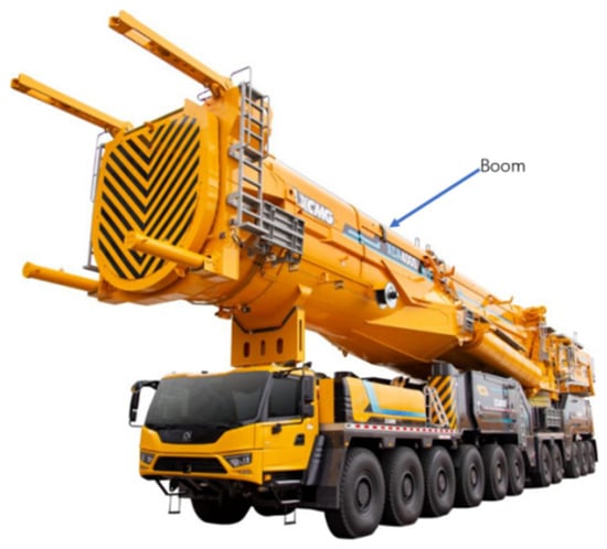
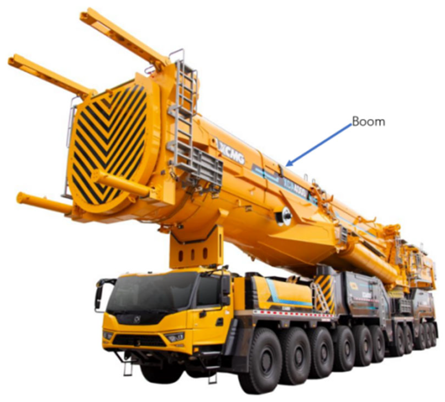
To address these challenges, an innovative simulation approach integrating the inherent strain method and the pre-deformation method (ISM-PDM) is proposed for controlling welding deformation in large welded box-section structures, such as crane booms shown in Figure 1. Given that crane booms generally exceed 15 m in length, a ‘local-segment-to-global-boom’ extrapolation strategy is adopted to enhance computational efficiency. Specifically, a representative boom segment containing the typical welded joints is intercepted from the full-scale boom, and finite element analyses are performed under conditions with and without pre-deformation. The simulated results are compared with experimental results to validate the proposed method. Subsequently, the optimal pre-deformation magnitude is determined and applied to the full-scale boom to predict welding deformation.
Figure 1.
The all-terrain crane boom.
2. Experimental Procedure
2.1. Structural Configuration of the Boom
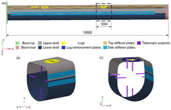
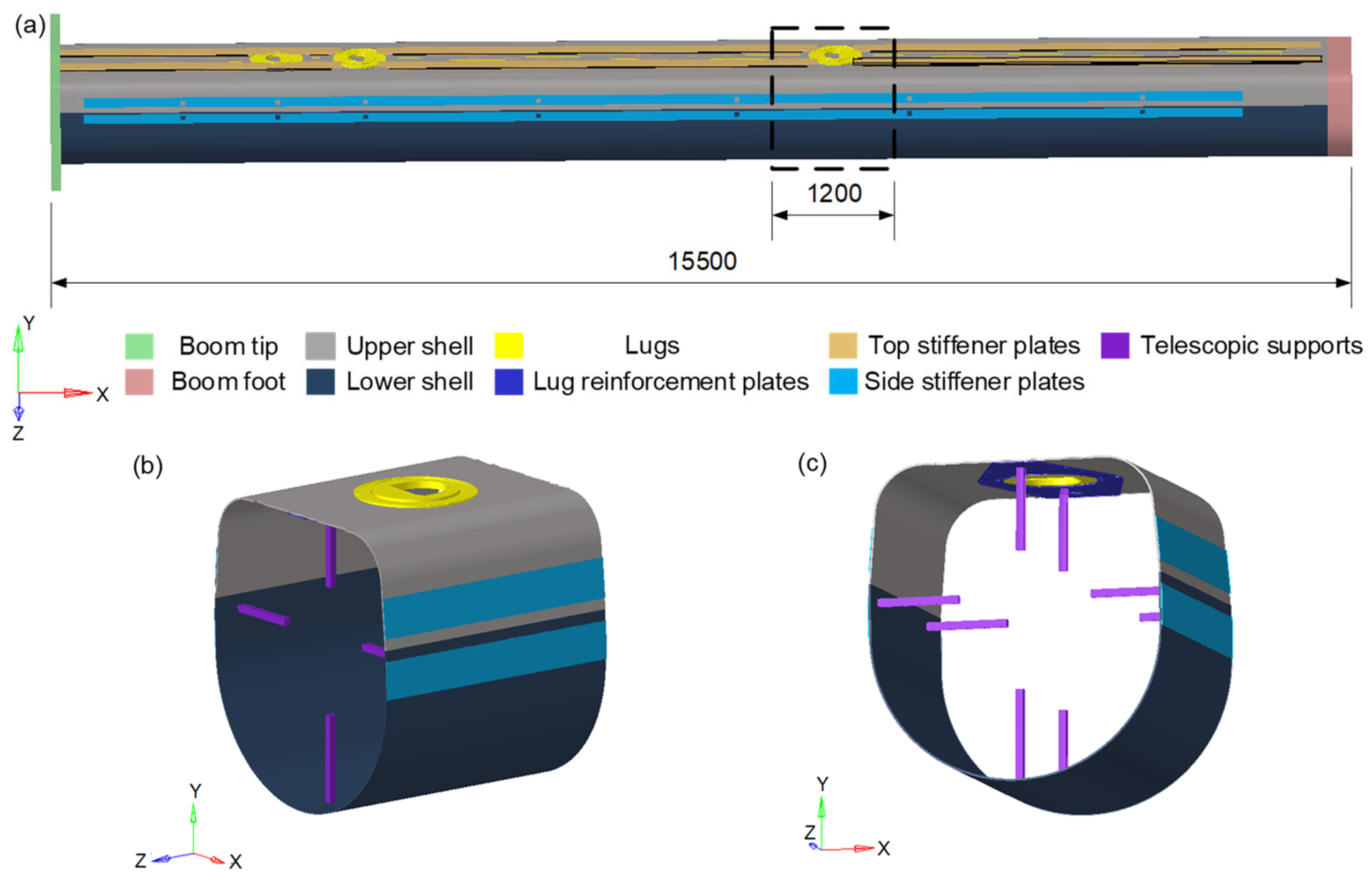
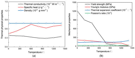
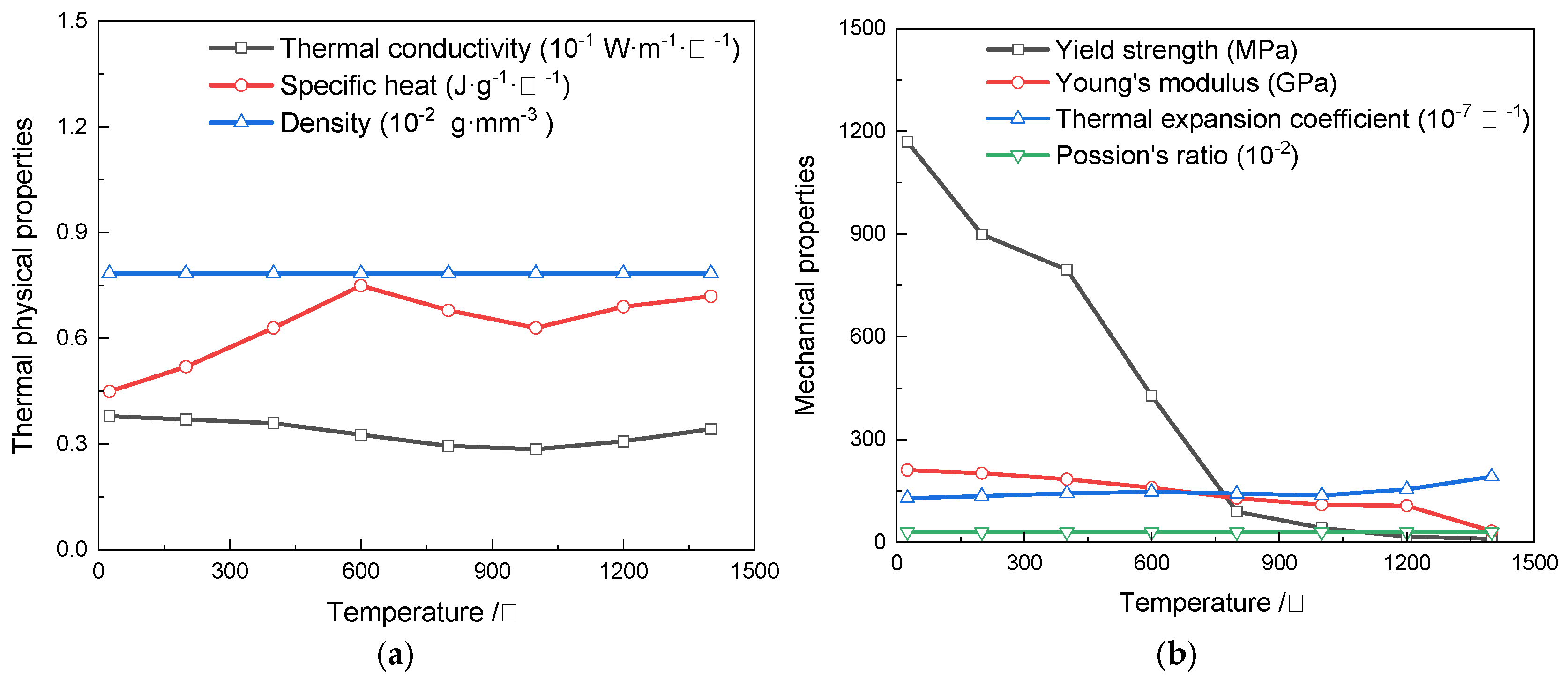
Figure 2 shows a three-dimensional model of the middle section of a crane boom. The middle section has a length of 15,500 mm, a width of 1300 mm, a height of 1400 mm, and a wall thickness of 11 mm. A representative boom segment (1200 mm long), including a lug and typical welded joints, is extracted from the full-scale boom for efficient numerical simulation, parameter optimization, and experimental validation. The boom segment adopts the same welding design and procedures as the full-scale boom. The middle boom section in Figure 2 consists of the head, tail, upper and lower shells, lugs, lug reinforcement plates, top and side stiffener plates, and telescopic supports. The upper shell, lower shell, and telescopic supports are made of Q1100 steel. The stiffener plates are made of Q960 steel, and the lugs are made of Q550 steel. Taking Q1100 as an example, Figure 3 presents the temperature-dependent material properties. In the elastic–plastic finite element analysis, since the boom is dominated by elastic deformation while plastic deformation is confined to local regions near the weld seams, the effect of hardening is neglected and an ideal elastoplastic model is adopted.
Figure 2.
Structural configuration of the boom: (a) the middle boom section, (b) exterior view of the boom segment, and (c) interior view of the boom segment.
Figure 3.
Temperature-dependent material properties of Q1100: (a) thermal physical properties, and (b) mechanical properties.
2.2. Welding Process Parameters
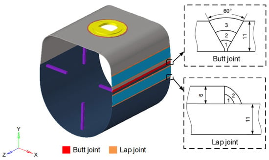
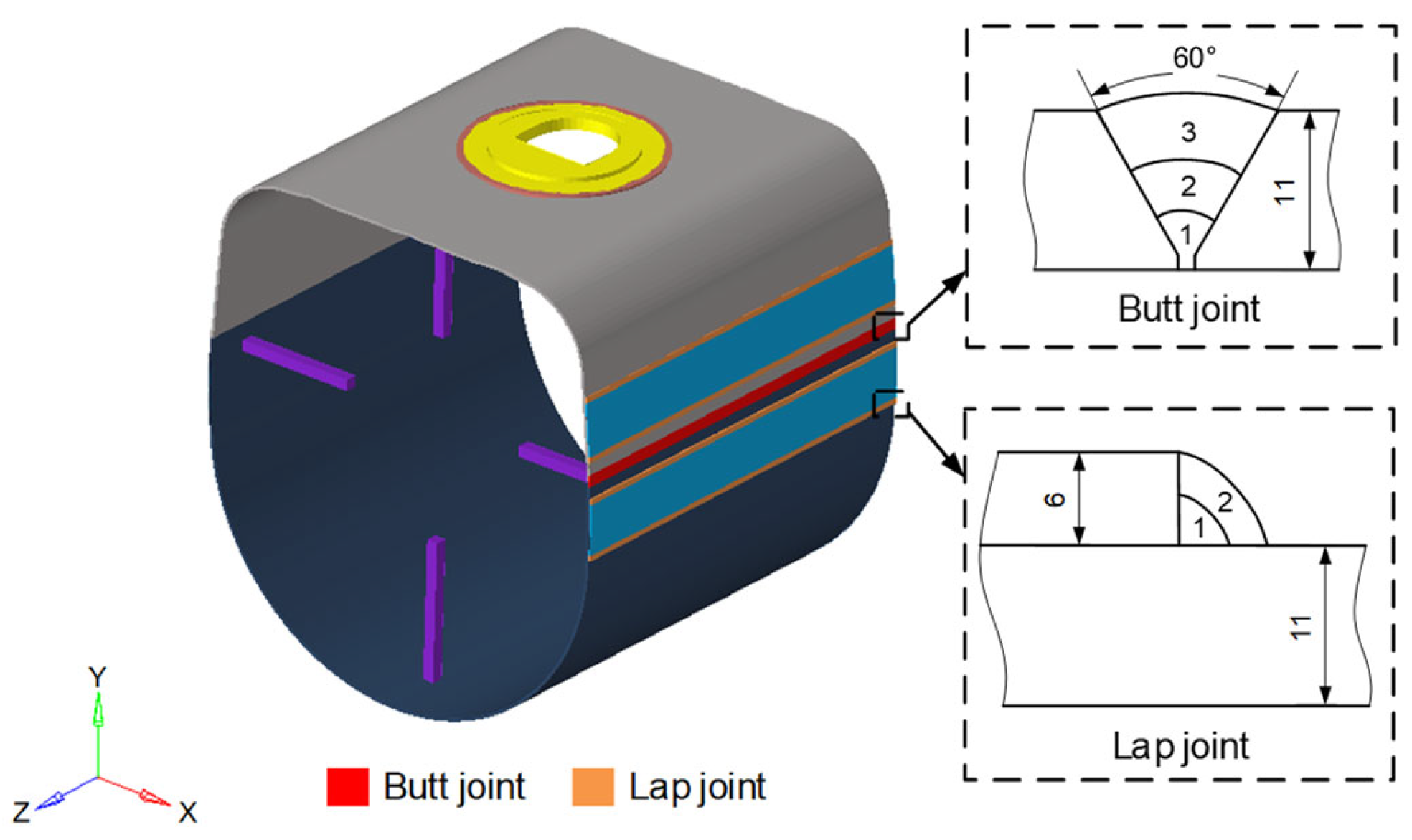
The welded joints of the crane boom are classified into two typical types: butt joints and lap joints. The geometries and dimensions of the typical welded joints are illustrated in Figure 4. The butt joint connects the upper and lower shells, while the lap joint connects the stiffener plates to the boom shells. The butt joint consists of three weld passes and is fabricated by laser-arc hybrid welding. The root pass was laser-welded, whereas the fill and cap passes were accomplished by laser-MAG (metal active gas) hybrid welding.
Figure 4.
The geometries and dimensions of the typical welded joints of the boom.
The laser beam had a spot diameter of approximately 0.5 mm. For laser welding, pure argon (99.99% purity) was used as the shielding gas, with the flow rate set to 20–25 L/min. For MAG welding, a 1.2 mm diameter filler wire was adopted, and the shielding gas was an 80% Ar +20% CO2 mixture, fed at a flow rate of 18–22 L/min. The lap joint between the stiffener plates and the boom shells was intermittently welded by MAG welding using the same filler wire and shielding gas composition as for the butt joint, but at a reduced flow rate of 15–20 L/min. Each weld segment was 100 mm in length, with a 100 mm gap between adjacent segments. Detailed welding parameters for the typical welded joints are summarized in Table 1.
Table 1.
Welding parameters for the typical welded joints.
2.3. Welding Deformation Measurement
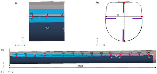
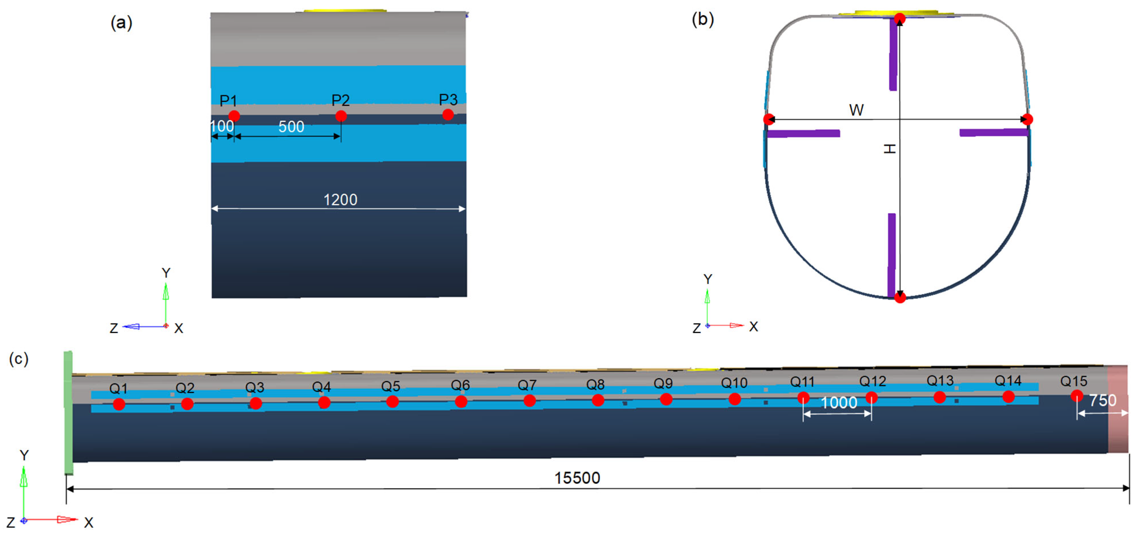
To verify the ISM-PDM approach and local–global strategy for crane booms, a laser rangefinder with 0.1 mm precision was used to measure the welding deformations of the boom segment and full-scale boom. Width and height measurements were recorded at 3 sections (500 mm apart, Figure 5a) on the boom segment and at 15 sections (1000 mm intervals, Figure 5c) on the full-scale boom, both before and after welding. The corresponding section is shown in Figure 5b.
Figure 5.
Welding deformation measurement of: (a) the boom segment, (b) the cross section, and (c) the boom.
3. Determination of Inherent Strain Parameters
3.1. Inherent Strain Theory
3.1.1. Inherent Strain Method
Inherent strain is the residual strain that remains in a component after external loads are removed, arising from non-uniform thermal cycling during welding and typically localized around the weld joints. Inherent strain is widely recognized as the fundamental cause of residual stresses and the resulting welding deformation. After the complete welding thermal cycle, the inherent strain ε* can be expressed as:
where εp, εT, εc, and εθ are the plastic strain, thermal strain, creep strain, and phase transformation strain, respectively.
After welding, the thermal strain vanishes. Owing to the short welding time, creep strain is negligible. Since the inherent strain parameters are subsequently calibrated through an iterative process that indirectly accounts for the transformation strain, the effect of phase transformation is neglected to enhance computational efficiency. Denoting as the inherent strain per unit area in the weld metal and heat-affected zone (HAZ), the total inherent strain W is obtained by integrating over the area A of the inherent strain zone, as expressed in Equation (2). For simplicity, this zone is approximated as a rectangular domain with a uniformly distributed inherent strain, leading to Equation (3):
where Bw and hy are the half-width and height of the inherent strain zone, respectively.
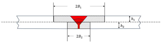
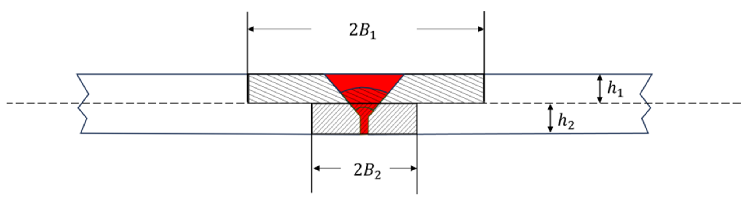
The through-thickness inherent strain application zones are shown in Figure 6, where the red region represents the weld zone and the hatched regions denote the inherent strain application zones. Two inherent strain application zones are defined in the thickness direction. B1 and B2 are the half-widths of the inherent strain application zones, and h1 and h2 are their heights. B1 and B2 correspond to the half-widths of the plastic zones, and h1 = h2 = t/2, where t is the plate thickness.
Figure 6.
Through-thickness inherent strain application zones.
The inherent strains in this study are implemented by applying thermal loads. The equivalent thermal load ΔTref is calculated as follows:
where α0 is the thermal expansion coefficient.
3.1.2. The Simulation Approach Based on the ISM-PDM
Pre-deformation applied near the weld seam suppresses weld metal contraction, thereby reducing welding deformation compared to that without pre-deformation. In the FEA based on the ISM, if the inherent strain parameters are taken from the condition without pre-deformation, the elastic deformation induced by the pre-deformation will be released after unloading. This leads to an overestimation of the predicted welding deformation relative to the measured deformation.
Two approaches are proposed to incorporate pre-deformation effects into ISM-based welding deformation predictions. In the first approach, the pre-deformation effect is accounted for by modifying the inherent strain. However, the modified inherent strains must be recalculated whenever the pre-deformation conditions change. Consequently, evaluating the influence of different pre-deformation magnitudes and positions requires two separate steps for each condition: deriving the inherent strain and performing an elastic analysis of the welded structure. This requirement compromises the high computational efficiency that makes the inherent strain method attractive.
The second method uses inherent strains obtained without pre-deformation and accounts for plastic behavior during finite element analysis based on the ISM. Although the applied pre-deformation is elastic at room temperature, the pre-deformed regions adjacent to the weld zones undergo high-temperature softening during welding. Consequently, part of the pre-deformation transforms into plastic strain at elevated temperatures. This plastic deformation is typically neglected in the conventional ISM, leading to an overprediction of welding deformation. To account for high-temperature plasticity, the yield strength of the inherent strain application zones is set to 200 MPa, approximately the yield strength of the HAZ at its peak temperature. At the same time, all other material properties remain unchanged. The advantage of this method is that it requires only a single derivation of the inherent strain during pre-deformation optimization, thereby significantly improving computational efficiency.
3.2. Extraction of Inherent Strain Using TEPFEA
The inherent strain parameters of two typical welded joints are obtained from the TEPFEA on small-sized welding test plates. The butt joint is composed of two 500 mm × 250 mm × 11 mm Q1100 steel plates. For the lap joint, the base plate is a 500 mm × 500 mm × 11 mm Q1100 steel plate, while the upper plate is a 500 mm × 250 mm × 11 mm Q960 steel plate. The welding design and procedures for these test plates are consistent with those described in Section 2.2. Figure 7 shows the finite element meshes of the butt joint and lap joint, in which local mesh refinement was applied to the weld metal and its adjacent regions. The butt joint model consists of 37,600 elements, whereas the lap joint model contains 40,298 elements. The element type is a 20-node thermal solid element for thermal analysis and a 20-node quadratic hexahedral solid element for deformation analysis. Three-point constraints are applied as boundary conditions to allow unrestrained deformation and suppress rigid-body motion.
Figure 7.
Finite element meshes and boundary conditions for the TEPFEA of: (a) the butt joint, and (b) the lap joint.
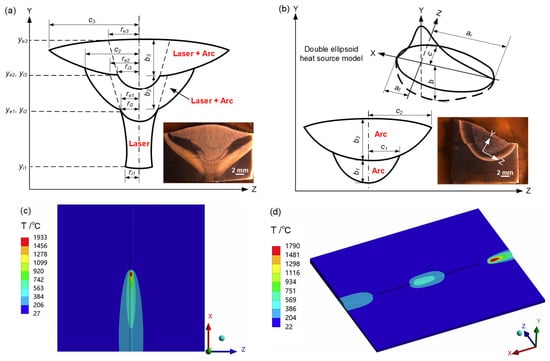
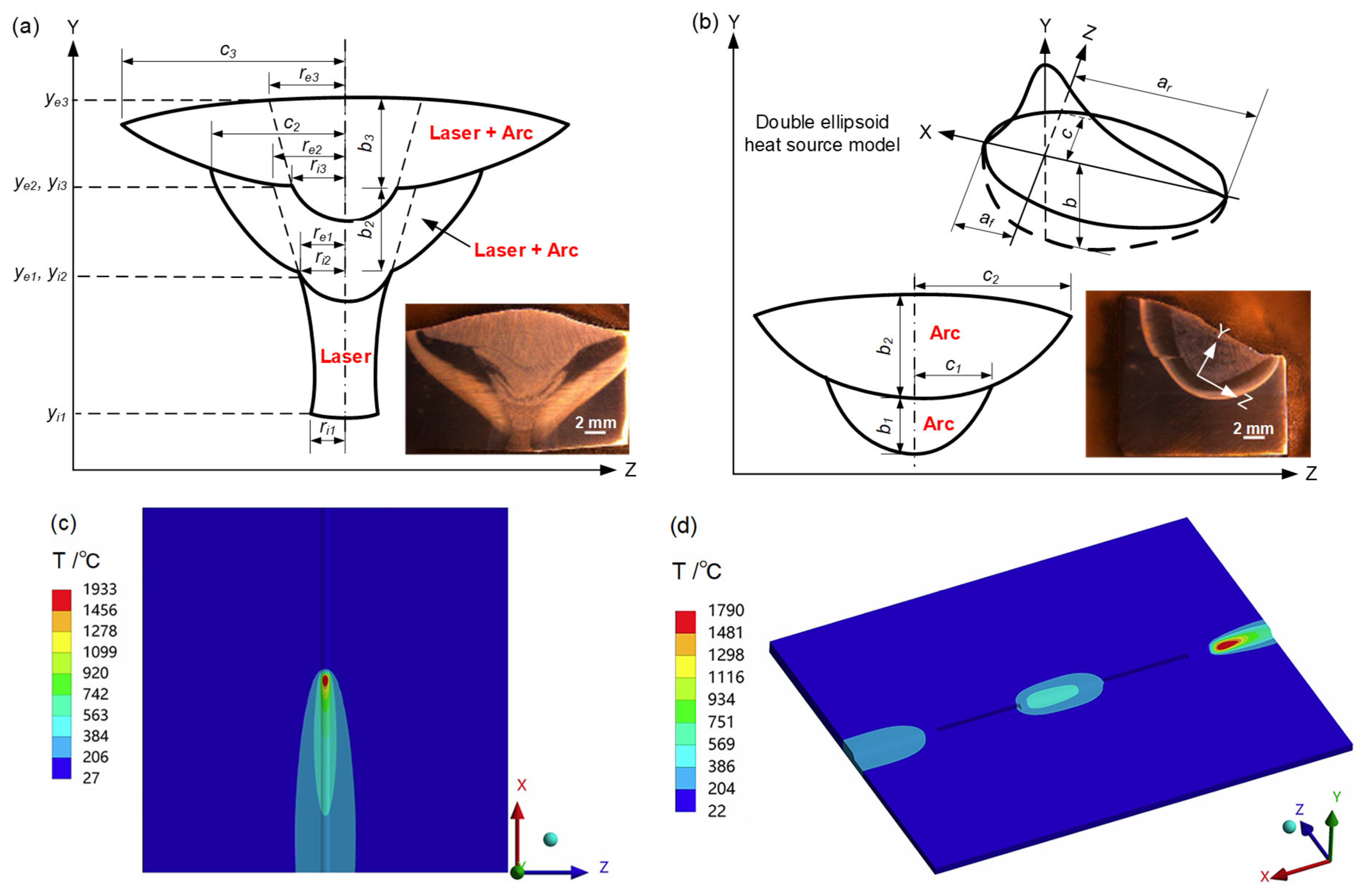
A conical Gaussian volumetric heat source is adopted for laser welding, with its radius varying linearly through the plate thickness to effectively capture the keyhole effect and attenuation of laser energy with depth. The heat flux distribution of the conical Gaussian volumetric heat source is given by Equation (5) [27]:
where ql(x, y, z, t) denotes the laser heat flux at position (x, y, z) and time t, with (x0, y0, z0) being the initial coordinates; Qel = ηlQl is the effective laser power, with ηl being the laser thermal efficiency and Ql the laser power; v is the welding speed; and ye, yi are the y-coordinates of the top and bottom surfaces, while re and ri are the corresponding radii of the conical heat source.
A double-ellipsoidal heat source is employed for arc welding. This model consists of two half-ellipsoids: the front half has a shorter semi-axis to represent the steep temperature gradient and narrow heating zone ahead of the heat source, whereas the rear half has a longer semi-axis to represent the milder temperature gradients and thermal trails caused by heat accumulation behind the heat source. The energy distribution coefficients ff and fr for the front and rear half-ellipsoids adjust the heat concentration on each side to accommodate various welding parameters; ff + fr = 2. The heat flux distributions of the double-ellipsoidal heat source are given in Equations (6) and (7).
Front half-ellipsoid:
Rear half-ellipsoid:
where qaf(x, y, z, t) and qar(x, y, z, t) denote the arc heat fluxes of the front and rear half-ellipsoids, respectively; Qea is the effective arc power, given by Qea = ηaUI, with ηa the arc thermal efficiency, U the welding voltage, and I the welding current; v is the welding speed; and af, ar, b, and c are the geometric coefficients of the double-ellipsoidal heat source.
For butt joints, a laser heat source is used for the root pass, while a laser-arc hybrid heat source is used for the filling and capping passes, as shown in Figure 8a. A thermal efficiency of 70% is adopted for laser welding and 80% for arc welding. The corresponding heat source coefficients are defined as follows: ri1 and re1 denote the laser heat source coefficients for the first pass; ri2 and re2 for the second pass; and ri3 and re3 for the third pass. Similarly, b2 and c2 are the arc heat source coefficients for the second pass, and b3 and c3 are those for the third pass. For the butt joint, ri1 = 1.0 mm, ri2 = 1.4 mm, ri3 = 1.7 mm, re1 = 1.4 mm, re2 = 2.1 mm, re3 = 3.3 mm, af2 = 2.7 mm, af3 = 5.6 mm, ar2 = 11.0 mm, ar3 = 22.3 mm, b2 = 4.0 mm, b3 = 4.6 mm, c2 = 4.6 mm, c3 = 9.3 mm. For lap joints, the double-ellipsoidal heat source described by Equations (6) and (7) is employed to simulate intermittent MAG welding, as shown in Figure 8b. A thermal efficiency of 80% is adopted for MAG welding. For the lap joint, af1 = 1.7 mm, af2 = 3.3 mm, ar1 = 6.9 mm, ar2 = 13.4 mm, b1 = 2.7 mm, b2 = 2.9 mm, c1 = 2.9 mm, c2 = 5.6 mm. The simulated temperature fields for the butt joint and lap joint are presented in Figure 8c and Figure 8d, respectively. The weld dimensions predicted by the TEPFEA are in good agreement with the experimental measurements.
Figure 8.
Simulation of welding temperature based on TEPFEA: (a) heat source schematic for the butt joint and (b) heat source schematic for the lap joint, (c) temperature distribution for the butt joint, and (d) temperature distribution for the lap joint.
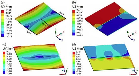
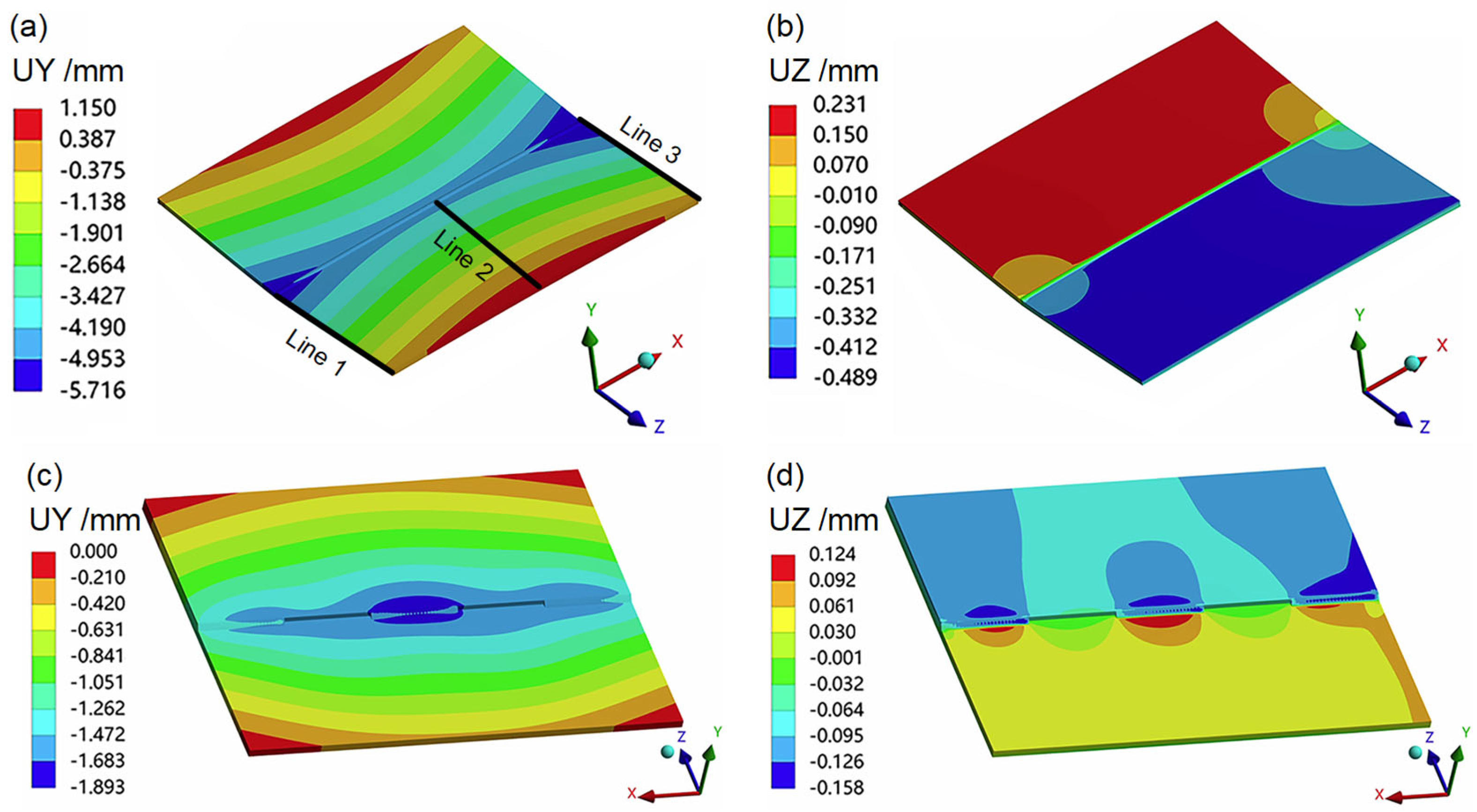
Figure 9 presents the simulated displacement fields for the butt and lap joints, respectively. The simulation results indicate that welding deformation is predominantly concentrated near the weld seam and is dominated by out-of-plane distortion and transverse shrinkage, with the out-of-plane distortion being significantly larger than the transverse shrinkage. Because the butt joint has a larger weld cross-sectional area and accumulates more welding heat input, it exhibits greater welding deformation than the lap joint.
Figure 9.
Simulated welding deformations using TEPFEA: (a) through-thickness deformation, (b) transverse deformation for the butt joint; (c) through-thickness deformation, and (d) transverse deformation for the lap joint.
A three-dimensional coordinate measuring machine (3D CMM) was used to measure the welding deformation of the butt and lap joints before and after welding. The angular distortions of the butt and lap joints were calculated from the measured welding deformation. Table 2 compares the measured angular distortions with the corresponding simulated results. The relative error between the simulated and experimental angular distortions is 8.6% for the butt joint and 11.1% for the lap joint, demonstrating that the established thermo-elastoplastic finite element models accurately characterize the welding deformation behavior of the typical welded joints.
Table 2.
Comparison of the measured and simulated angular distortions of the typical welded joints.
The inherent strains for the primary welds on the boom were derived by integrating the plastic strains calculated using the TEPFEA, in accordance with Equation (2). These integrated values were adopted as the initial values for the inversion and correction of the inherent strains. The welding deformation simulated using the initial inherent strains was compared with the measured values. Iterative adjustments to the inherent strains were made to minimize discrepancies between the simulated and measured welding deformation until the relative errors were reduced to within 10%. The inherent strain parameters for the typical welded joints are listed in Table 3. Iterative calibration of the inherent strains enhanced the accuracy of welding deformation predictions for the crane boom. Both the TEPFEA and the calibration procedure were applied to all other welds.
Table 3.
Inherent strain parameters of the typical welded joints.
4. Prediction of Welding Deformation in the Boom Segment with and Without Pre-Deformation
4.1. Finite Element Model of the Boom Segment
In the finite element model, the telescopic supports are simplified as rigid bodies and connected to the boom through bonded constraints. No sliding or separation occurs at the interface between the boom and supports during the preloading and welding stages, which reproduces the spot-welded condition. The finite element analysis of the boom is divided into three stages: pre-deformation, welding, and support removal. In the pre-deformation stage, prescribed displacements are applied to the telescopic supports to represent their extension. In the welding stage, inherent strains are applied to the boom to simulate the welding process. In the support removal stage, the telescopic supports are deactivated to represent their removal.
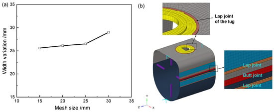
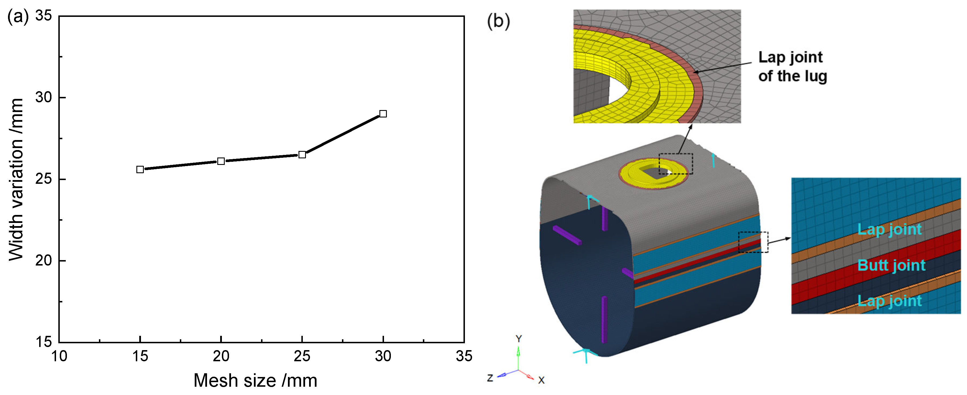
Mesh convergence analysis was performed for the boom segment, as shown in Figure 10a. The predicted deformation differed by 0.5 mm between the 15 mm and 20 mm mesh sizes, corresponding to a relative deviation of 1.9%. Therefore, the boom segment was meshed with hexahedral elements of 20 mm × 20 mm × 5.5 mm, resulting in 32,629 elements (Figure 10b). The element type was a 20-node quadratic hexahedral solid element. To prevent rigid-body motion, three-point constraints were applied to the model. The inherent strains were assumed to be uniformly distributed, and the calibrated values were subsequently imposed on the corresponding weld zones and adjacent regions.
Figure 10.
Finite element model of the boom segment: (a) mesh convergence analysis, and (b) finite element mesh and boundary conditions.
4.2. Prediction of Welding Deformation Without Pre-Deformation
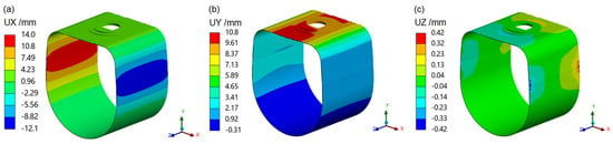
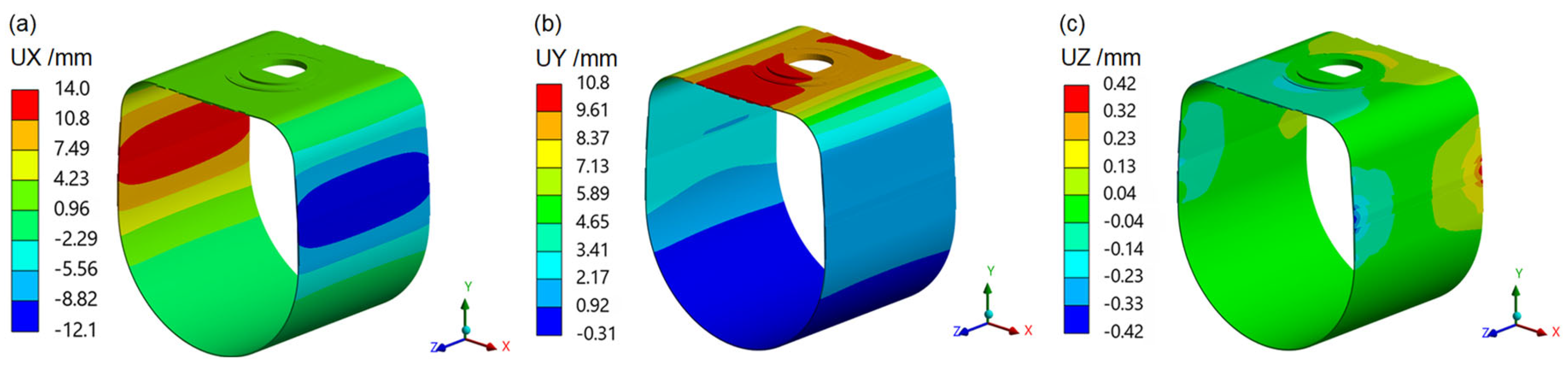
Figure 11 shows that the welding deformation of the boom segment occurs predominantly in the width and height directions of its cross-section. The width shrinkage is induced by the welds between the upper and lower shells and between the stiffener plate and the boom shells. The height variation results from the contraction of the weld between the lug and the upper shell and from the expansion caused by the width contraction of the boom segment. Because the weld between the upper and lower shells requires a larger volume of filler metal than that between the lug and the upper shell, the welding-induced section width variation is considerably greater than the height variation. In the height direction, the expansion induced by the width contraction exceeds the contraction caused by the weld between the lug and the upper shell, thus resulting in the net expansion in the height direction (Figure 11b).
Figure 11.
Displacement contours of the boom segment without pre-deformation in the: (a) X, (b) Y, and (c) Z directions.
The welding deformations at the measurement points indicated in Figure 5a,b were extracted to determine the width and height variations in the boom segment. The predicted welding deformations are compared with the measured values in Figure 12. The results reveal that the boom segment shrinks in the width direction without pre-deformation, with slightly larger shrinkage at the center than at the two ends. The maximum simulated width shrinkage reaches 24.9 mm, whereas the corresponding measured value is 25.3 mm. In the height direction, the boom segment expands. Due to the restraint imposed by the weld of the lug in the middle, the expansion at the center is smaller than that at both ends. The maximum simulated height variation is 9.0 mm, while the measured value is 10.1 mm. Overall, the height variation is smaller than the width variation in the absence of pre-deformation. The predicted welding deformations agree well with the experimental trends, with relative errors below 11%.
Figure 12.
Comparison of predicted and measured welding deformations for the boom segment without pre-deformation.
4.3. Prediction of Welding Deformation with Pre-Deformation
In the absence of pre-deformation, the welding deformation of the boom segment exceeds the allowable tolerances (ΔW ≤ 10 mm and ΔH ≤ 15 mm) for subsequent machining and assembly. To suppress this deformation, telescopic supports are positioned near the welds on the inner wall of the boom to impose pre-deformation that counteracts welding shrinkage. Figure 11 and Figure 12 indicate that width shrinkage is the dominant factor contributing to the deformation of the boom segment. With the width-direction pre-deformation applied, width shrinkage is substantially reduced, thereby mitigating the height expansion induced by width contraction. Since the height shrinkage induced by the lug welds exceeds the height expansion caused by the width shrinkage, a net inward indentation occurs in the vicinity of the lugs. Accordingly, pre-deformation in the height direction is also required near the lugs.
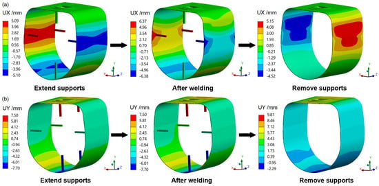
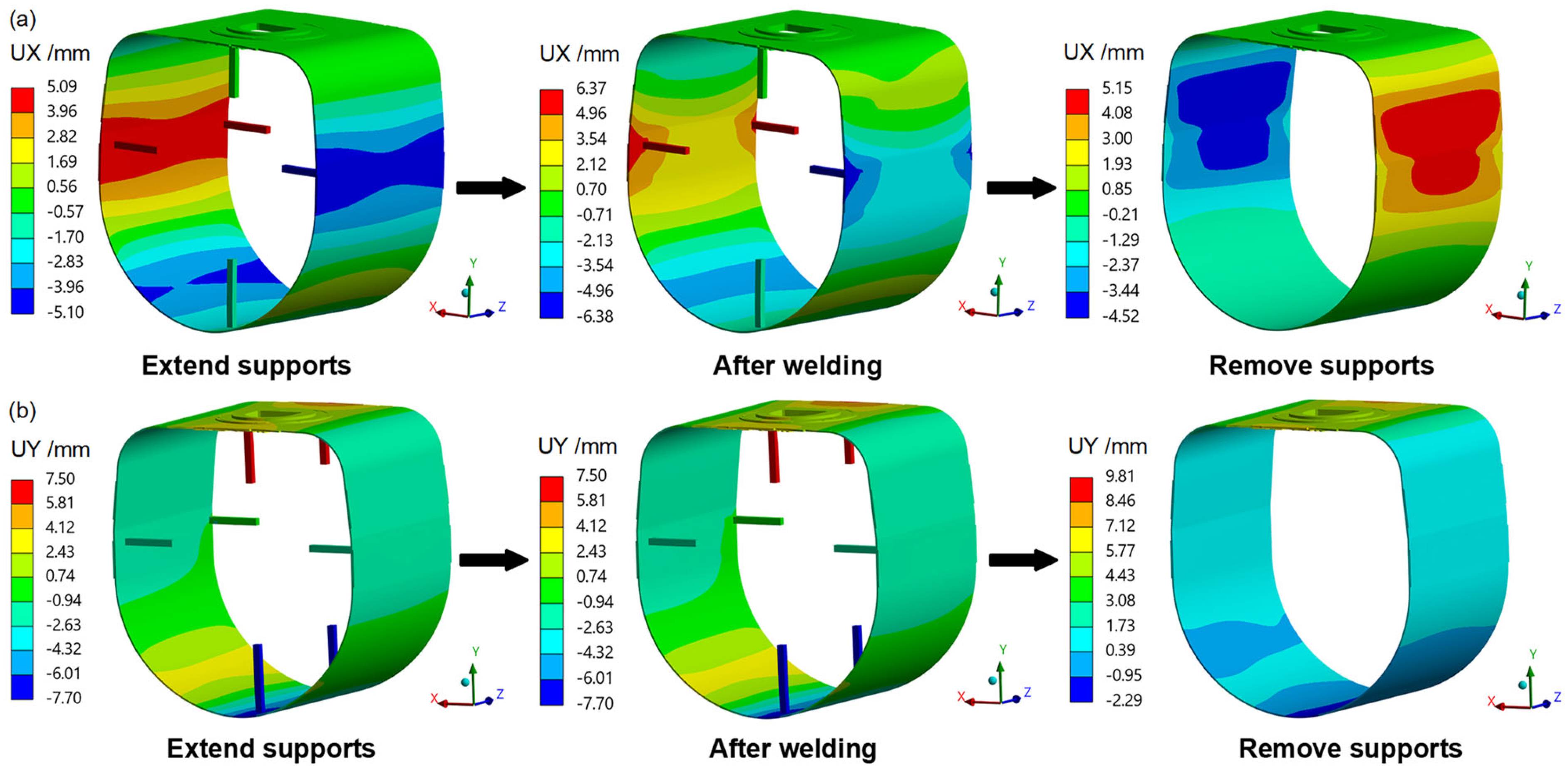
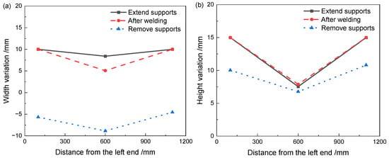
Figure 13 and Figure 14 illustrate the evolution of width and height variations in the boom segment after pre-deformation is applied. When the telescopic supports are extended, greater expansion occurs at the ends adjacent to the supports than in the central region of the boom segment. After welding, the width expansion in the central region decreases because of shrinkage of the weld between the upper and lower shells. In contrast, the expansion at the two ends remains unchanged. Height variation during welding is low because the shrinkage induced by lug welding counteracts the expansion caused by the boom segment’s width shrinkage. Following the removal of the telescopic supports, elastic rebound occurs. The segment width shrinks due to welding of the upper and lower shells. The height increases due to the width’s shrinkage. Since the supports are positioned near the ends, the width and height variations at the two ends are smaller than those in the middle. With pre-deformation applied, both width and height variations in the boom segment are controlled to approximately 10 mm, significantly lower than the 25 mm observed without pre-deformation. These results confirm that pre-deformation can effectively restrain welding deformation in crane boom structures.
Figure 13.
Evolution of welding deformation in the boom segment along the (a) width and (b) height directions.
Figure 14.
Section width and height variations in the boom segment at different stages: (a) width, (b) height.
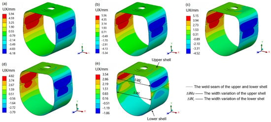
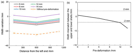
To investigate the influence of pre-deformation magnitude on boom structures and identify the optimal value, welding deformation is compared for magnitudes of 6, 8, 10, 12 and 14 mm, as shown in Figure 15, Figure 16, Figure 17 and Figure 18. Figure 15 and Figure 16 present the width deformation of the boom segment after support removal. The simulation results reveal that the width shrinkage of the boom segment decreases with increasing pre-deformation magnitude, reaching a minimum of 14 mm.
Figure 15.
Width deformation of the boom segment for various pre-deformation magnitudes in the width direction: (a) 6 mm, (b) 8 mm, (c) 10 mm, (d) 12 mm, and (e) 14 mm.
Figure 16.
Effect of pre-deformation on width variation. (a) Axial width variation curves with different pre-deformation values, (b) Variation of width mismatch between upper and lower shells with pre-deformation.
Figure 17.
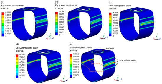
Equivalent plastic strain of the boom segment under different pre-deformations: (a) 6 mm, (b) 8 mm, (c) 10 mm, (d) 12 mm, and (e) 14 mm.
Figure 18.
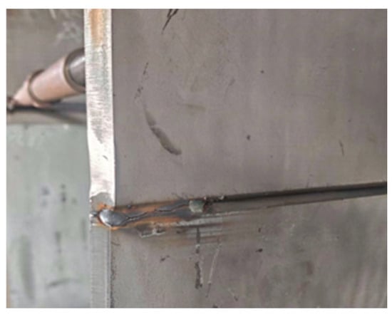
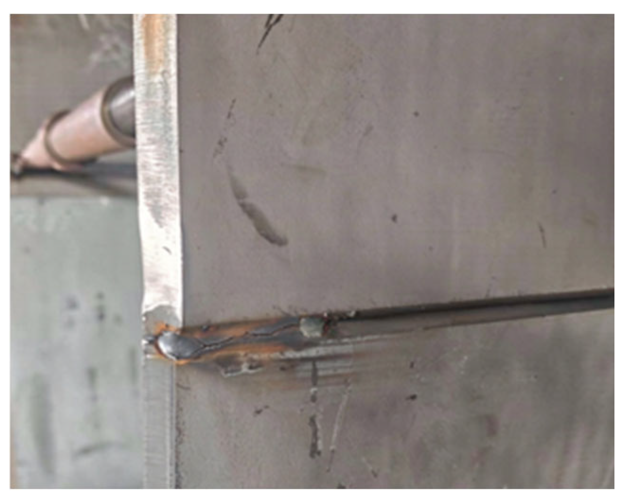
Cracking at a tack weld induced by excessive pre-deformation.
Figure 16a compares the width shrinkage of the boom segment under various pre-deformation magnitudes. It reveals that pre-deformation drastically reduces the width shrinkage from 25 mm to less than 12 mm, confirming that the PDM effectively suppresses welding deformation in boom structures. When the pre-deformation magnitude is below 10 mm, the width shrinkage remains above 10 mm. When the pre-deformation magnitude reaches 14 mm, the width shrinkage of the boom segment transitions to outward expansion. As shown in Figure 15 and Figure 16b, the difference between the width shrinkage of the upper and lower shells, denoted as ΔWu and ΔWl, exceeds 2 mm at pre-deformation magnitudes of 12 mm and 14 mm. Such a discrepancy can readily induce misalignment and consequently impair welding quality.
The equivalent plastic strains under various pre-deformation magnitudes are compared in Figure 17. The equivalent plastic strain at the weld between the upper and lower shells increases with the pre-deformation magnitude. The pre-deformation is applied to the lower shell via telescopic supports. Larger pre-deformation magnitudes lead to greater misalignment between the upper and lower shells, thereby increasing the equivalent plastic strain near the weld zone. As shown in Figure 17, the equivalent plastic strain at this weld increases drastically under 12 mm and 14 mm pre-deformation, accompanied by pronounced strain localization. This indicates that excessive pre-deformation triggers incompatible deformation across the weld seam, leading to cracking of the tack welds, as shown in Figure 18. To avoid welding defects induced by excessive misalignment, the equivalent plastic strain in the shells must be strictly controlled.
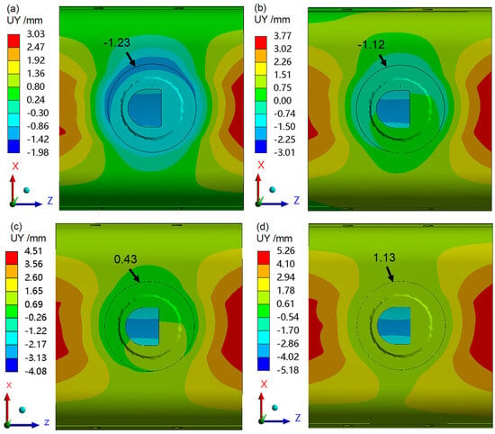
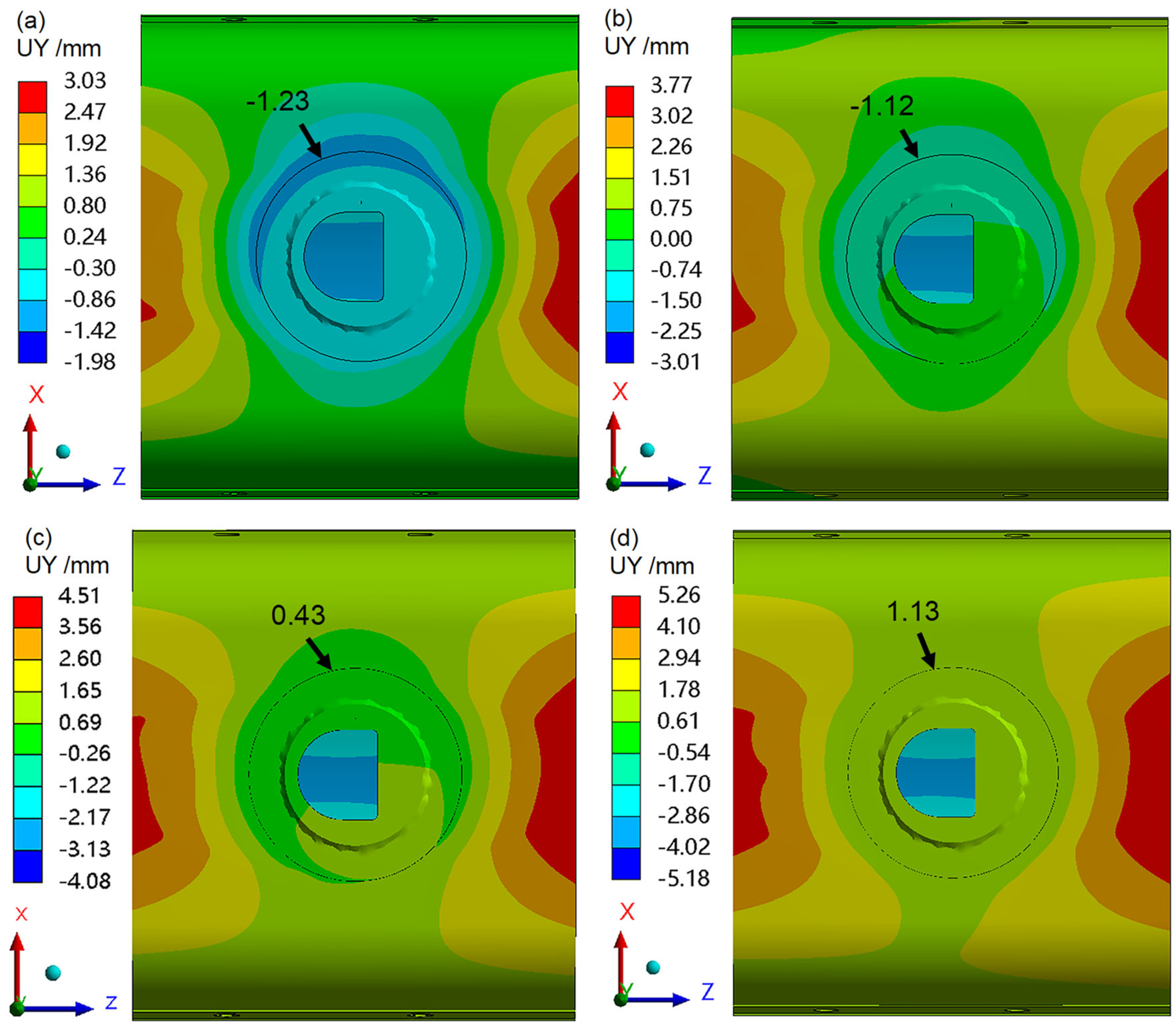
The telescopic supports are positioned near the lugs along the height direction to mitigate local inward indentation at the lug welds. Since the inward indentation is mainly caused by the lug welds, the height deformation induced by lug welding is studied under different pre-deformation magnitudes in the height direction, as shown in Figure 19. Local inward indentation occurs at the lug weld under height-direction pre-deformations of 9 mm and 12 mm. The height deformation under a height-direction pre-deformation of 15 mm is smaller than that under 18 mm. Therefore, a pre-deformation of 15 mm in the height direction is adopted for the boom.
Figure 19.
Height deformation near the lug for various pre-deformation magnitudes: (a) 9 mm, (b) 12 mm, (c) 15 mm, and (d) 18 mm.
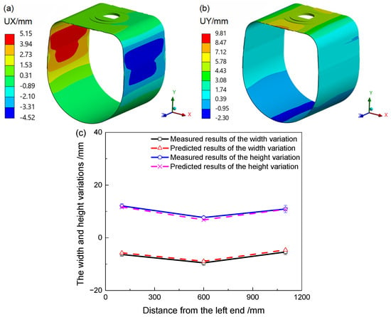
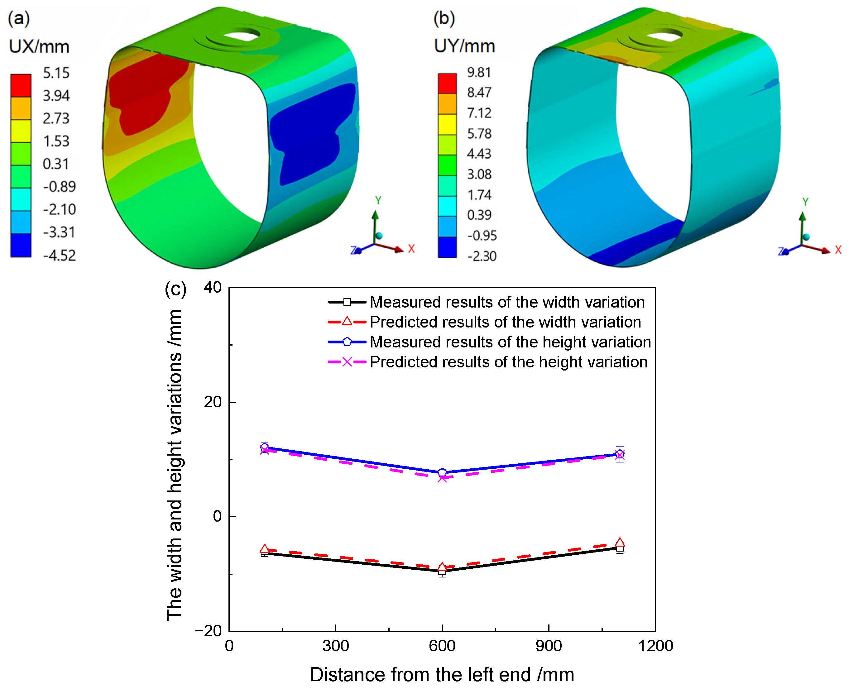
The predicted and measured welding deformations of the boom segment with optimal pre-deformation magnitudes (10 mm in width and 15 mm in height) are presented in Figure 20. The simulated width shrinkage is 8.9 mm, compared with a measured value of 9.5 mm. The simulated height expansion is 12.3 mm, while the measured value is 12.1 mm. These results confirm that the welding deformation of the pre-deformed boom segment, as predicted by the ISM-PDM, agrees well with the experimental measurements.
Figure 20.
Welding deformations of the boom segment under optimal pre-deformation: (a) width-direction, (b) height-direction, and (c) comparison between predicted and measured results.
5. Prediction and Control of Welding Deformation in a Crane Boom
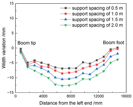
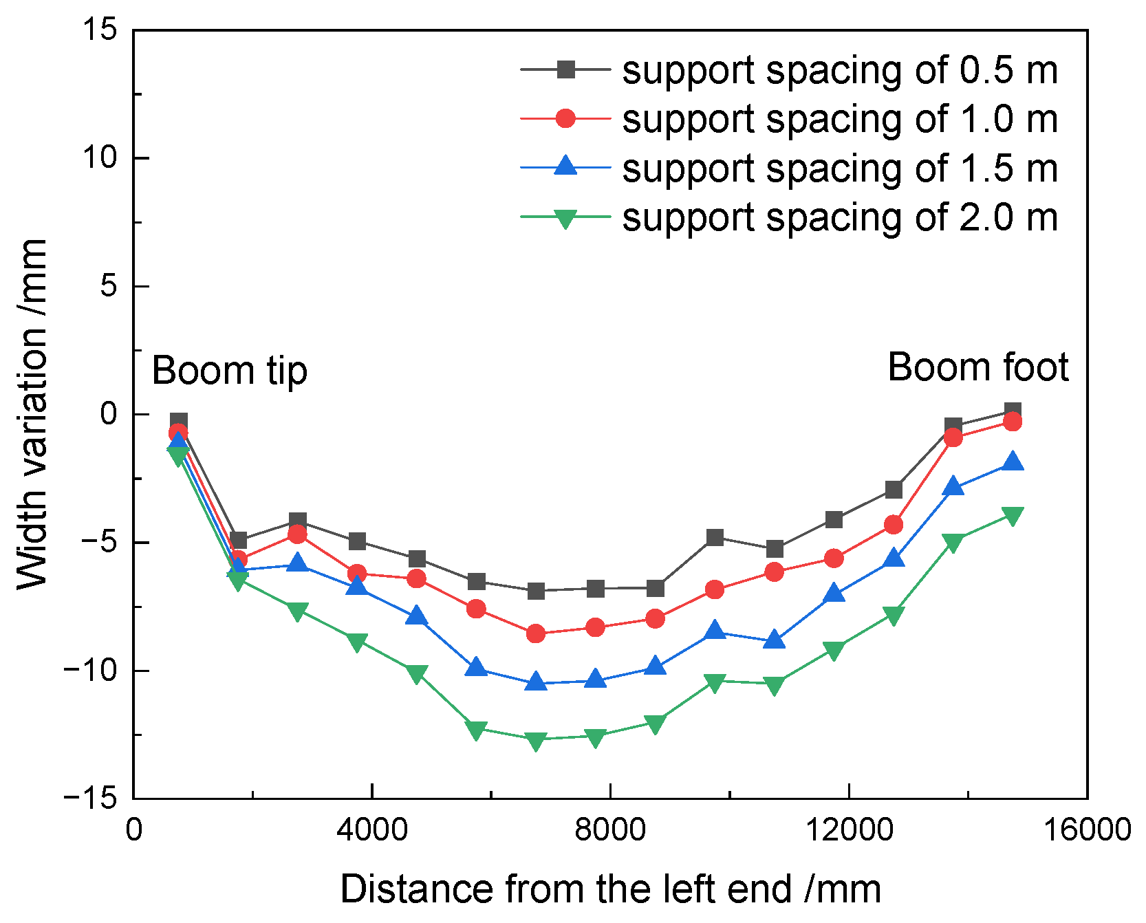
The ISM-PDM is extended from the boom segment to the full-scale boom to evaluate its effectiveness in controlling welding deformation. A three-point constraint scheme is applied to the full-scale boom to suppress rigid-body motion. As shown in Figure 21, the width shrinkage decreases as the support spacing decreases. When the support spacing is 1.0 m, the width shrinkage of the boom is less than 10 mm, which meets the manufacturing requirement. When the support spacing is reduced to 0.5 m, the excessive number of supports lowers manufacturing efficiency. Therefore, the supports are spaced at 1.0 m intervals in the transverse direction and positioned adjacent to the lugs in the vertical direction.
Figure 21.
Effect of support spacing on the width variations in the boom.
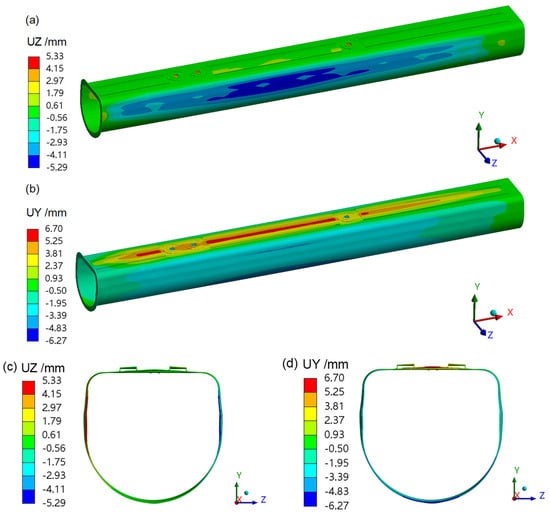
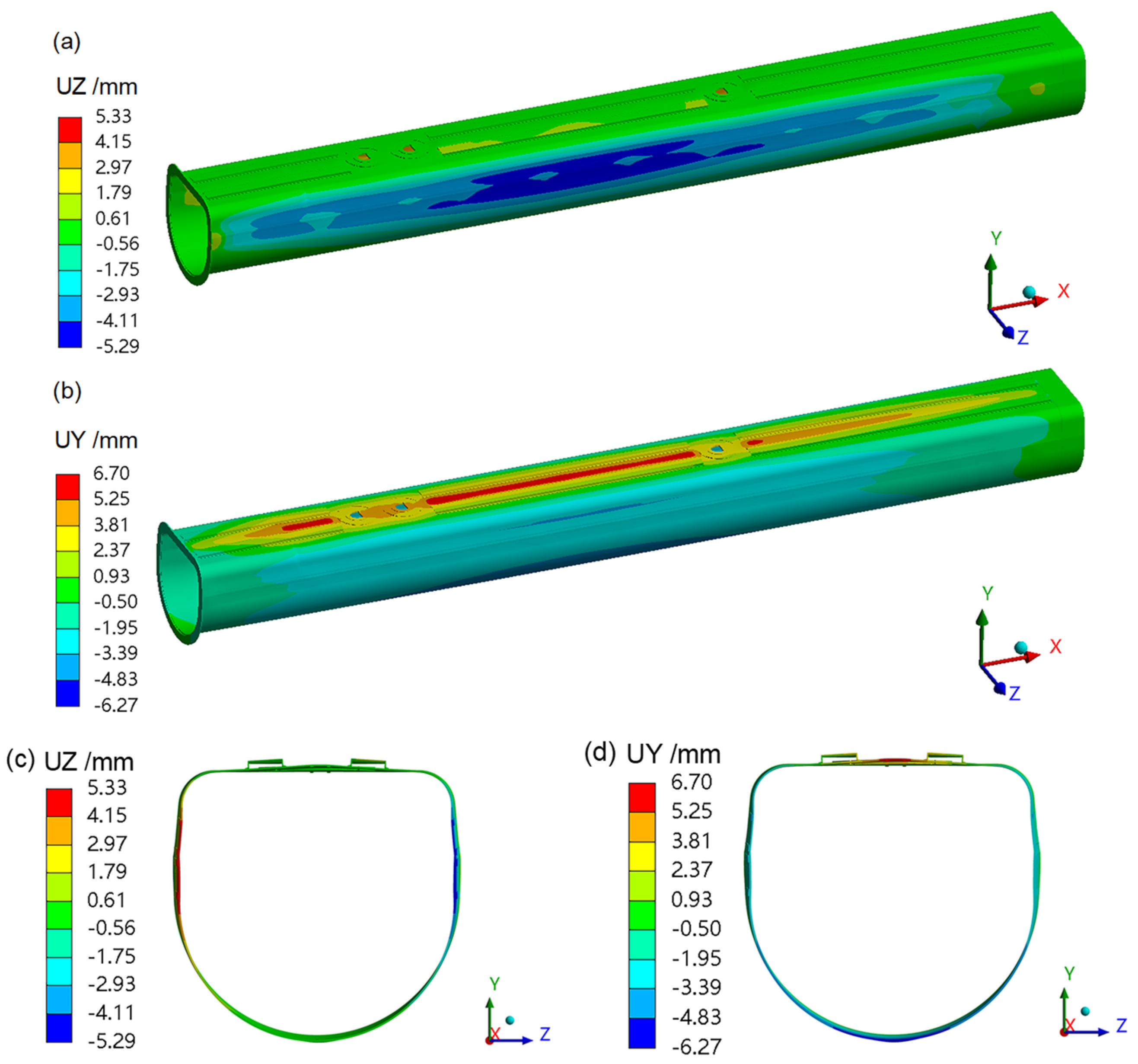
The simulated welding deformations of the full-scale boom are presented in Figure 22 and Figure 23. The width variation in the boom is predominantly due to shrinkage, whereas the height variation is predominantly due to expansion. Both the width shrinkage and height expansion are localized in the central region of the boom, owing to the reinforced structures and enhanced stiffness at the boom tip and root. The maximum variation in both width and height is approximately 10 mm. Moreover, the non-uniform arrangement of lug welds on the upper shell results in vertically varying deformation along the boom length. While the width shrinkage of the box section promotes height expansion, the localized welding of the lugs causes shrinkage in the vicinity. The combined effect results in a net height expansion, although the magnitude of the expansion is locally reduced around each lug.
Figure 22.
Displacement contours of the boom: (a) width direction, (b) height direction, (c) cross-sectional view in the width direction, and (d) cross-sectional view in the height direction.
Figure 23.
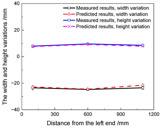
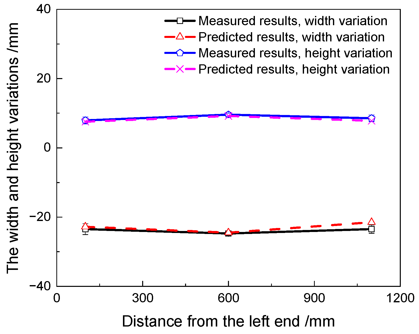
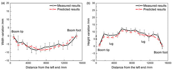
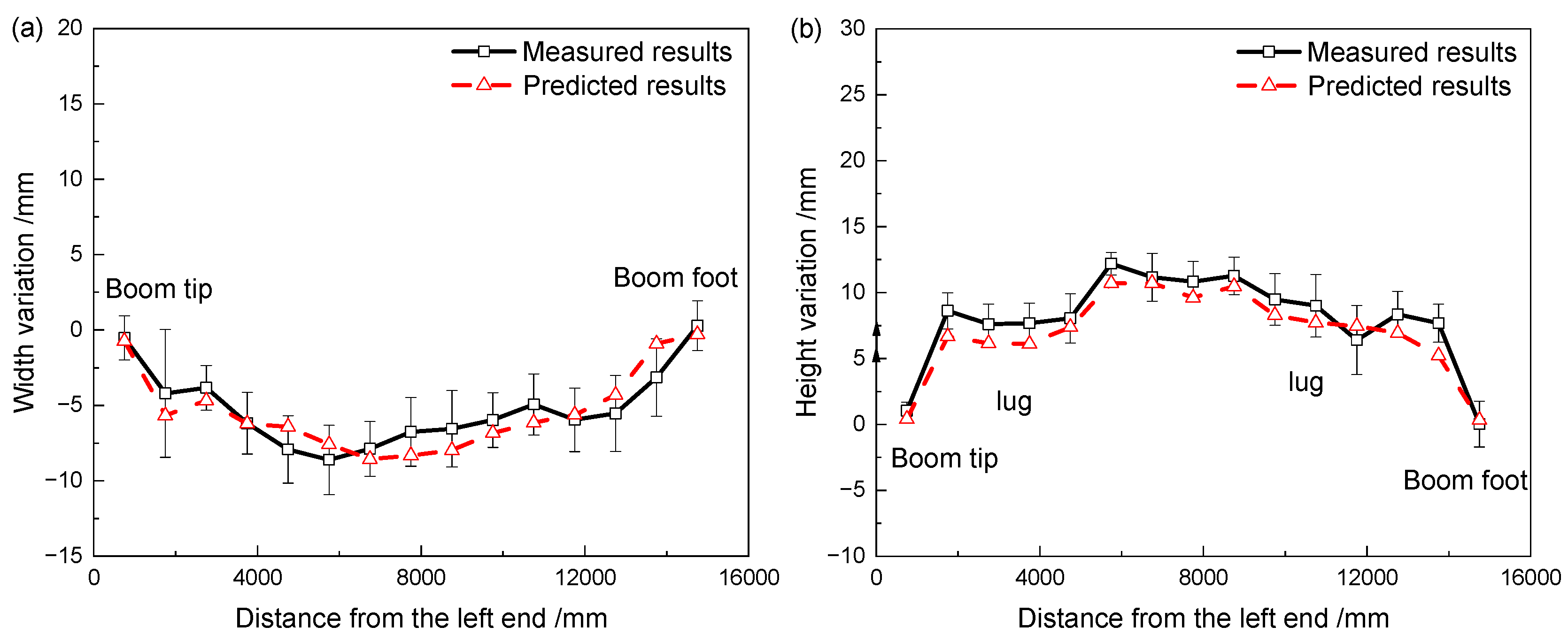
Comparison of predicted and measured welding deformations of the boom with pre-deformation: (a) width-direction deformation, and (b) height-direction deformation.
Based on the measuring point layout shown in Figure 5b,c, the width and height variations at the corresponding cross-sections were extracted from the simulation model and compared with the experimental data, as shown in Figure 23. The measured data were obtained from repeated experiments on six samples of the same boom type. The points in Figure 23 represent the average values of the six samples, and the error bars indicate the standard deviation. The predicted results exhibit trends consistent with the measured results, with larger variations in width and height in the central region of the boom, attributable to the enhanced stiffness at the boom tip and root. The maximum deviation between the simulated and measured variations is less than 2 mm, representing less than 20% of the peak deformation, thereby satisfying the accuracy requirements for engineering applications.
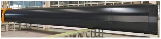
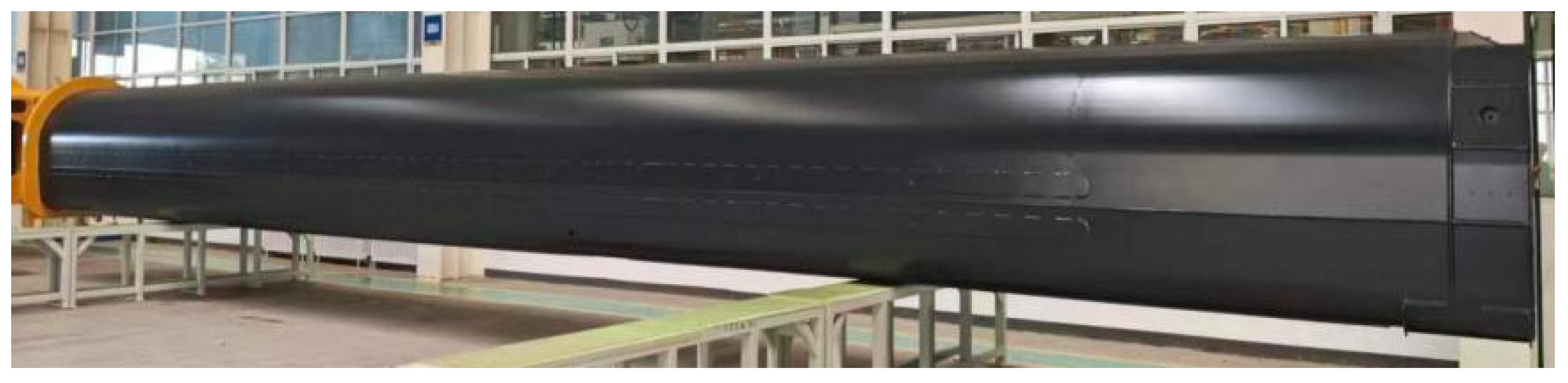
Figure 24 shows the finished boom manufactured using the aforementioned pre-deformation control strategy. The proposed method effectively prevents assembly gaps caused by excessive welding deformation in crane booms. The predicted and measured deformation trends show good agreement for the boom segment with and without pre-deformation, as well as for full-scale booms, with all deviations falling within acceptable ranges. This confirms that the ISM-PDM can accurately predict the deformation evolution of crane booms, and validates the rationality of the ‘local-segment-to-global-boom’ simulation strategy. Furthermore, both experimental and simulated results indicate that pre-deformation reduces boom deformation by approximately 50% in the width direction, demonstrating that the method effectively suppresses welding deformation. For the specific boom structure investigated in this study, optimal deformation control is achieved with pre-deformation magnitudes of approximately 10 mm in the width direction and 15 mm in the height direction. These findings have significant engineering applications for the dimensional control of crane booms during welding fabrication.
Figure 24.
The machined boom after pre-deformation treatment.
6. Conclusions
The proposed ISM-PDM accurately predicts the deformation trend of crane booms and effectively suppresses welding deformation. The ‘local-segment-to-global-boom’ simulation strategy provides an efficient solution for controlling welding deformation in crane booms and similar box-type structural components. The main conclusions are summarized as follows:
(1) Without pre-deformation, the welding deformation of the boom segment is mainly induced by the butt welds between the upper and lower shells, leading to significant width shrinkage of approximately 25 mm, which exceeds the allowable tolerances and impairs weld quality and operational safety. The height variation is governed by the combined effects of width shrinkage and the lug welds, and its magnitude is much smaller than that of the width variation.
(2) The simulated results agree well with the experimental measurements for boom segments with and without pre-deformation, as well as for full-scale booms, with all deviations being less than 20% of the peak deformation. These results demonstrate that the ISM-PDM can accurately capture the welding deformation behavior of crane booms, thereby validating the rationality of the “local-segment-to-global-boom” simulation strategy.
(3) The PDM can efficiently suppress welding deformation in crane booms. However, excessively large pre-deformation magnitudes induce incompatible deformation at the butt welds between the upper and lower shells, thereby deteriorating weld quality. For the specific boom structure investigated in this study, the optimal pre-deformation magnitudes are approximately 10 mm in the width direction and 15 mm in the height direction, which reduce the maximum boom deformation by approximately 50%.
Author Contributions
Conceptualization, J.-B.L. and Y.-W.S.; Methodology, J.-B.L.; Software, J.-B.L.; Validation, Y.-W.S.; Formal analysis, Y.-W.S.; Resources, J.-B.L. and Y.-W.S.; Writing—original draft, J.-B.L.; Writing—review & editing, J.-B.L.; Visualization, Y.-W.S.; Project administration, Y.-W.S. All authors have read and agreed to the published version of the manuscript.
Funding
This research received no external funding.
Data Availability Statement
No new data were created or analyzed in this study.
Conflicts of Interest
The authors declare no conflict of interest.
References
- Zhou, Q.H.; Zhu, X.Y.; Sun, J.M.; Li, J. Control of welding residual stress and deformation for the rod support of a crane. Int. J. Simul. Model. 2022, 21, 501–512. [Google Scholar] [CrossRef] [Scilit]
- Zhu, J.; Khurshid, M.; Barsoum, I.; Barsoum, Z. Computational weld-mechanics assessment of welding distortions in a large beam structure. Eng. Struct. 2021, 236, 112055. [Google Scholar] [CrossRef] [Scilit]
- Rong, Y.; Xu, J.; Huang, Y.; Zhang, G. Review on finite element analysis of welding deformation and residual stress. Sci. Technol. Weld. Join. 2018, 23, 198–208. [Google Scholar] [CrossRef] [Scilit]
- Lee, J.; Perrera, D.; Chung, H. Multi-pass welding distortion analysis using layered shell elements based on inherent strain. J. Mar. Sci. Eng. 2021, 9, 632. [Google Scholar] [CrossRef] [Scilit]
- Gupta, O.P. An efficient approach to analysis of distortion in complex welded structures. Sci. Technol. Weld. Join. 2018, 23, 428–433. [Google Scholar] [CrossRef] [Scilit]
- Liang, W.; Murakawa, H. An inverse analysis method to estimate inherent deformations in thin plate welded joints. Mater. Des. 2012, 40, 190–198. [Google Scholar] [CrossRef] [Scilit]
- Wang, W.; Maeda, S.; Ikushima, K.; Shibahara, M. Development of simplified mechanical model for welding deformation in multi-pass welding. J. Manuf. Mater. Process 2026, 10, 96. [Google Scholar] [CrossRef] [Scilit]
- Wang, L.; Miao, Y.; Hu, G.; Zhao, Y.; Deng, Q. Numerical simulations and experimental verification of T-structure welding deformation using the step-by-step loading inherent strain method. Metals 2023, 13, 1312. [Google Scholar] [CrossRef] [Scilit]
- Wang, Y.X.; Zhang, P.; Hou, Z.G.; Li, C.Z. Inherent strain method and thermal elastic-plastic analysis of welding deformation of a thin-wall beam. J. Mech. 2008, 24, 301–309. [Google Scholar] [CrossRef] [Scilit]
- Ha, Y.S.; Jang, C.D.; Kim, J.T.; Mun, H.S. Analysis of post-weld deformation at the heat-affected zone using external forces based on the inherent strain. Int. J. Precis. Eng. Manuf. 2007, 8, 56–62. [Google Scholar]
- Yuan, K.; Gao, C.; Lin, Y.; Yu, H. A new analytical model for predicting the welding deformation of large welded plates with equivalent moments. Sci. Technol. Weld. Join. 2024, 29, 391–404. [Google Scholar] [CrossRef] [Scilit]
- Kim, Y.; Kim, J.; Kang, S. A study on welding deformation prediction for ship blocks using the equivalent strain method based on inherent strain. Appl. Sci. 2019, 9, 4906. [Google Scholar] [CrossRef] [Scilit]
- Kim, T.J.; Jang, B.S.; Kang, S.W. Welding deformation analysis based on improved equivalent strain method considering the effect of temperature gradients. Int. J. Nav. Archit. Ocean. Eng. 2015, 7, 157–173. [Google Scholar] [CrossRef] [Scilit]
- Madrid, J.; Lorin, S.; Söderberg, R.; Hammersberg, P.; Wärmefjord, K.; Lööf, J. A virtual design of experiments method to evaluate the effect of design and welding parameters on weld quality in aerospace applications. Aerospace 2019, 6, 74. [Google Scholar] [CrossRef] [Scilit]
- Nguyen, L.; Buhl, J.; Israr, R.; Bambach, M. Analysis and compensation of shrinkage and distortion in wire-arc additive manufacturing of thin-walled curved hollow sections. Addit. Manuf. 2021, 47, 102365. [Google Scholar] [CrossRef] [Scilit]
- Li, C.; Zhai, H.; Zhu, L.; Liu, Z.; Ma, J.; Zhu, X.; Liu, Q. Numerical investigation of welding deformation diminution for double shell structure using the layered inherent strain. Nucl. Eng. Technol. 2025, 57, 103208. [Google Scholar] [CrossRef] [Scilit]
- Tong, Y.; Ge, Z.; Zhuo, X.; Shen, G.; Li, D.; Li, X. Research on welding deformation for box girder of bridge crane based on thermal elasto-plastic theory. Adv. Mech. Eng. 2018, 10, 168781401877588. [Google Scholar] [CrossRef] [Scilit]
- Park, D.H.; Yang, J.H.; Kim, S.H.; Kim, J.H.; Lee, J.M. A study on welding sensitivity assessment and deformation control of international maritime organization type C liquefied natural gas fuel tank support structures using the direct inherent strain method. J. Mar. Sci. Eng. 2024, 12, 2161. [Google Scholar] [CrossRef] [Scilit]
- Shen, Y.; Liu, S.; Yuan, M.; Dai, X.; Lan, J. Immune optimization of double-sided welding sequence for medium-small assemblies in ships based on inherent strain method. Metals 2022, 12, 1091. [Google Scholar] [CrossRef] [Scilit]
- Liu, S.; Wu, Z.; Liu, H.; Zhou, H.; Deng, K.; Wang, C.; Liu, L.; Li, E. Optimization of welding parameters on welding distortion and stress in S690 high-strength steel thin-plate structures. J. Mater. Res. Technol. 2023, 25, 382–397. [Google Scholar]
- Zhang, Y.; Ying, Y.; Liu, X.; Wei, H. Deformation control during the laser welding of a Ti6Al4V thin plate using a synchronous gas cooling method. Mater. Des. 2016, 90, 931–941. [Google Scholar] [CrossRef] [Scilit]
- Price, D.A.; Williams, S.W.; Wescott, A.; Harrison, C.J.C.; Rezai, A.; Steuwer, A.; Peel, M.; Staron, P.; Koçak, M. Distortion control in welding by mechanical tensioning. J. Manuf. Process 2007, 12, 620–633. [Google Scholar] [CrossRef] [Scilit]
- Totonchi, B.A.; Aghazadeh, K.; Zakeri, B.; Attarnejad, R. Distortion analysis and optimization of grillage structure assembly process by finite element inherent strain method (FE-ISM)—Part 2: Post-weld flame straightening and experimental verification. Weld. World 2026, 70, 3733–3756. [Google Scholar] [CrossRef] [Scilit]
- Liu, Y.; Wangi, P.; Fang, H.; Ma, N. Mitigation of residual stress and deformation induced by TIG welding in thin-walled pipes through external constraint. J. Mater. Res. Technol. 2021, 15, 4636–4651. [Google Scholar] [CrossRef] [Scilit]
- Dai, P.; Mi, D.; Guo, B.; Yue, X.; Sun, J.; Li, Z.; Deng, D. Bending deformation control in a laser-welded long straight structure by elastic pre-bending technique. J. Manuf. Process 2023, 107, 485–495. [Google Scholar] [CrossRef] [Scilit]
- Liang, W.; Mao, Z.; Deng, D. Predicting welding deformation of panel structure using inherent strain method with consideration of structural restraint. Results Eng. 2025, 27, 107038. [Google Scholar] [CrossRef] [Scilit]
- Liu, S.; Kouadri-Henni, A.; Gavrus, A. DP600 dual phase steel thermo-elasto-plastic constitutive model considering strain rate and temperature influence on FEM residual stress analysis of laser welding. J. Manuf. Process 2018, 35, 407–419. [Google Scholar] [CrossRef] [Scilit]



Disclaimer/Publisher’s Note: The statements, opinions and data contained in all publications are solely those of the individual author(s) and contributor(s) and not of MDPI and/or the editor(s). MDPI and/or the editor(s) disclaim responsibility for any injury to people or property resulting from any ideas, methods, instructions or products referred to in the content. |
© 2026 by the authors. Licensee MDPI, Basel, Switzerland. This article is an open access article distributed under the terms and conditions of the Creative Commons Attribution (CC BY) license.