


Abstract
In this paper, the reaction behavior of an iron oxide–carbon composite briquette (ICCB) under an H2-H2O-N2 atmosphere was experimentally and numerically studied. The employed ICCB had a composition of 21.07 wt.% Fe3O4, 49.89 wt.% FeO,16.46 wt.% carbon, and 18.73 wt.% gangue. A mathematical model was developed to describe the reaction process. Isothermal and non-isothermal experiments were conducted using a thermal-gravimetric device. The reliability of the model was confirmed by comparing its predictions with isothermal experimental data. Simulation and experimental results under non-isothermal conditions revealed that, in the reduction process of ICCB, the main reactions were the stepwise reduction of iron oxide by hydrogen and the carbon gasification by H2O, and reactions involving the reduction of iron oxide by CO and gasification by CO2 were found to be negligible. The compressive strength of ICCB presented a V-type change as temperature increased, and its minimum was 1274 N/briquette at 1273 K, The ICCB presented a successive contraction, achieving a final volume shrinkage degree of 15%. Phase changes in ICCB included the conversion of iron oxides to metallic iron and the decomposition of fayalite. The development of morphology in ICCB consisted of disintegration of the sintered matrix, formation of irregular iron grains, and the emergence of a metallic iron network.
1. Introduction
The blast furnace (BF) remains the dominant ironmaking technology worldwide owing to its high productivity and cost-effectiveness. Steel produced through the BF–basic oxygen furnace (BOF) route accounts for more than 70% of global steel production [1,2]. However, BF process ironmaking is responsible for approximately 70% of the total energy consumption and CO2 emissions associated with steel production [3,4]. This substantial energy demand and carbon footprint are increasingly at odds with global carbon neutrality objectives. Consequently, the development of low-carbon ironmaking technologies has become an urgent priority for the steel industry.
Charging iron oxide–carbon composite briquettes (ICCB) is considered an effective approach to reducing the fuel rate in BF and has been implemented in several industrial practices [5,6,7]. In ICCB charging, ICCB acts as a critical feedstock, providing internal carbon sources and improving the reducibility of the burden. The close contact between iron oxide and carbon in ICCB enhances the reaction interface, thereby creating favorable kinetic conditions for iron oxide reduction. Each ICCB functions as an independent self-reducing system and can undergo rapid reduction at appropriate temperatures [8,9,10,11]. This approach offers an effective way to reduce coke-specific consumption in BF. In parallel, many iron and steel enterprises are actively exploring hydrogen-based BF ironmaking technologies nowadays. For example, the COURSE50 Project in Japan aims to partially replace carbon-based reductants in the BF with hydrogen, targeting a 30% reduction in CO2 emissions [12], Similarly, in China, Baowu Steel Group has conducted industrial experiments on a hydrogen-rich carbon-circulating oxygen BF, achieving a reduction of 45 kg of coke per ton of hot metal in the fuel rate and approximately 30% reduction in CO2 emissions [13,14]. Hydrogen-based BF operation is typically realized through injecting hydrogen-rich gases via the tuyeres. The hydrogen gases include H2, methane, and coke oven gas (COG) [15,16,17]. The use of hydrogen-rich gas in the blast furnace offers significant advantages, as hydrogen possesses strong reducibility and enables CO2-free reduction, making it a promising alternative to carbon-based reductants and improving reduction efficiency while mitigating environmental impact. Potentially, ICCB charging and hydrogen-based ironmaking technologies can be implemented simultaneously in BF operation. However, previous studies on the reaction behavior of ICCB in the BF were mainly conducted under N2-CO–CO2 atmospheres [18,19,20,21], while its behavior under the N2-H2-H2O system was rarely considered. This was primarily because the H2 and H2O contents in the conventional BF gas are low. With the large-scale injection of hydrogen-rich gases, H2 and H2O are expected to become considerable components in BF gas. Therefore, the effects of the N2-H2-H2O atmosphere on ICCB reaction and metallurgical properties require further study.
In this work, a mathematical model was developed first. The reduction behavior of ICCB under an H2-H2O-N2 atmosphere was investigated numerically and experimentally. By analyzing the reduction kinetics, main reactions, changes in metallurgical properties, and microstructural evolution, the reaction behavior of ICCB under the N2-H2-H2O atmosphere was elucidated. The findings aim to provide support for combining ICCB charging and hydrogen-rich gas injection in BF ironmaking, thereby contributing to the development of low-carbon BF ironmaking technologies.
2. Experimental
2.1. Sample Preparation
The ICCB was prepared by cold briquetting followed by heat treatment, and the details are given in Ref. [18]. The raw materials included non-coking coal, iron oxide fines, and quartz fines. The coal fines had an average particle size of 90 μm, and their composition is listed in Table 1. The iron oxide and SiO2 fines were chemical reagents supplied by Sinochem Inc. (Shanghai, China). During preparation, the raw materials were mixed at a mass ratio of iron oxide:coal:quartz = 75:20:5. The chemical composition of the prepared ICCB is given in Table 2. The prepared ICCB samples were cylindrical, with a diameter of 15 mm, a height of 15 mm, and an average mass of 5.16 g.
Table 1.
Proximate and ultimate analyses of the coal fines (wt.%).
Table 2.
Composition of ICCB (wt.%).
2.2. Isothermal Reduction Tests
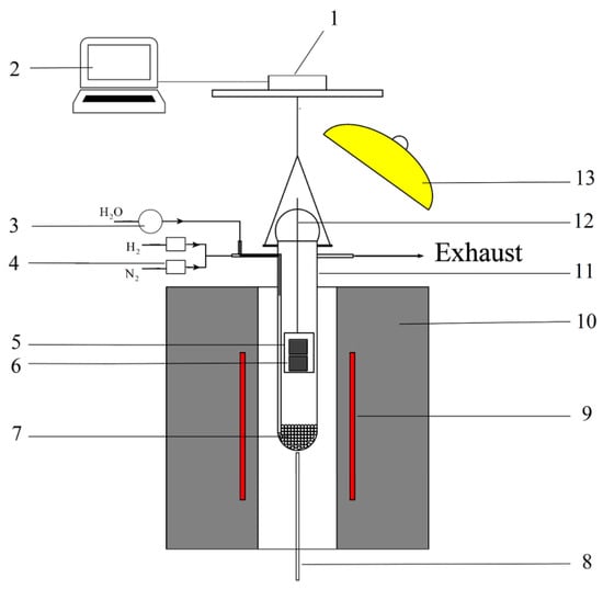
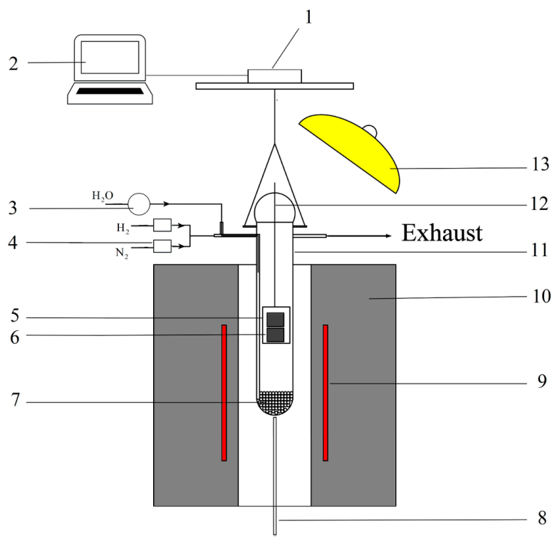
A schematic diagram of the experimental apparatus is presented in Figure 1. The system consisted of a vertical tube furnace, a quartz reaction tube, a gas supply unit, a steam generation unit, and a mass-loss measurement system. The furnace provided a uniform hot zone with a length of 50 mm. The quartz reaction tube had an inner diameter of 40 mm and a length of 800 mm. Sample mass loss was monitored using a load sensor with a capacity of 100 g and an accuracy of 0.01 g, which was connected to a laptop for data recording. The reaction tube was suspended from the sensor by a stainless-steel chain. An infrared heater (IR heater) was installed near the upper outlet of the reaction tube to prevent steam condensation. In the gas supply system, the flow rates of N2 and H2 were controlled using mass-flow controllers. Steam was generated by vaporizing deionized water, which was introduced directly into the reaction tube through a fine copper tube. The water flow rate was regulated using a peristaltic pump.
Figure 1.
Schematic illustration of the experimental setup: (1) mass-loss sensor, (2) computer, (3) peristaltic pump, (4) mass-flow controller, (5) stainless sample basket, (6) sample, (7) alumina balls, (8) thermocouple, (9) MoSi2 heating elements, (10) furnace, (11) quartz tube, (12) suspending wire for sample basket, and (13) IR heater.
For each experiment, three briquette samples were loaded into the sample holder and positioned above the hot zone of the reaction tube. The sample holder was suspended from the top of the reaction tube using a stainless-steel wire. Before heating, the reaction tube was completely sealed and purged with high-purity N2. The furnace was heated to the target temperature in the hot zone while maintaining an N2 atmosphere within the reaction tube. After the temperature had stabilized for 10 min, the sample holder was lowered into the hot zone. Simultaneously, the inlet gas was switched from pure N2 to an H2–H2O–N2 gas mixture (H2:H2O:N2 = 40:10:50, vol%) under a total flow rate of 2000 mL·min−1 (standard temperature and pressure (STP)). The mass loss of the samples was continuously recorded throughout the reaction. The mass-loss fraction of the ICCB samples was calculated according to Equation (1).
where m0 is the initial mass of the briquette, g; mt is the mass of the briquette at time t, g; mo is the mass of iron oxide oxygen in the briquette, g; and mc is the mass of carbon in the briquette, g.
After 30 min of reaction, the reaction tube was removed from the furnace, and the samples were rapidly cooled by purging with N2. The reacted samples were then subjected to chemical analysis to determine the total iron content, the iron oxide reduction fraction, and the coal gasification fraction. The analytical methods and calculation procedures have been described elsewhere [18].
2.3. Non-Isothermal Tests
The experimental setup used in this study was identical to that described in the previous section. In each experiment, the furnace was first heated to 1073 K. Three briquettes were placed in the sample holder. After the temperature had stabilized for 10 min under an N2 atmosphere, the sample holder was lowered into the hot zone. Simultaneously, the inlet gas was switched from N2 to an H2–H2O–N2 gas mixture (H2:H2O:N2 = 40:10:50, vol%) with a total flow rate of 2 L·min−1 (STP). The furnace was then heated at 6 K·min−1 to the predetermined temperature. Upon reaching the target temperature, the reaction tube was withdrawn from the furnace and purged with N2 to rapidly cool the samples. The cooled samples were then subjected to analyses of volume shrinkage degree, compressive strength, phase composition, and microstructure. Measurement methods for compressive strength and volume shrinkage degree are described elsewhere [18,22]. Phase identification was conducted using an M21X X-ray diffractometer (XRD, MAC Science Co., Tokyo, Japan), and the sample microstructure was examined using an EV018 scanning electronic microscope (SEM, ZEISS Co., Oberkochen, Germany).
3. Mathematical Model
A kinetic model is useful for understanding the reaction behavior and reaction mechanisms of ICCB. In the present study, a kinetic model was developed based on the model reported in Refs. [18,23]. The ICCB is assumed to be a sphere with a diameter of 15 mm. Both gas and solid phases are considered in the model. The reactions occurring within the ICCB include the stepwise reduction of iron oxide by CO, the stepwise reduction of iron oxide by H2, carbon gasification by CO2, and carbon gasification by H2O. In addition, the model accounts for both internal gas diffusion within the briquette and external mass transfer between the briquette surface and the surrounding gas atmosphere. The gas phase is assumed to be an ideal gas mixture consisting of CO, CO2, H2, H2O, and N2. The solid phase comprises Fe2O3, Fe3O4, FeO, metallic Fe, carbon, and gangue minerals.
The reduction rates of iron oxide fines by CO and H2 are expressed by Equation (2) and Equation (3), respectively [24].
where i = 1, 2, and 3, representing the stepwise reductions of Fe2O3 to Fe3O4, Fe3O4 to FeO, and FeO to Fe using CO, respectively; and i = 4, 5, and 6, representing the stepwise reductions using H2, ri, is the rate of reduction i, mol·m−3·s−1; Ki is the equilibrium constant of stepwise reduction i; ki is the rate constant of reduction i, m·s−1; fi is the reduction fraction of stepwise reduction i, and f1 = f4, f2 = f5, f3 = f6, -; T is temperature, K; PCO, PCO2, PH2, PH2O are partial pressures of CO, CO2, H2, and H2O, respectively, Pa; R is the gas constant, 8.314 J·mol−1·K−1; ags is the specific gas–solid interface area of iron oxide particles in ICCB, m2·m−3.
The gasification rates of coal by CO2 and by H2O are expressed as Equations (4) and (5), respectively [25].
where r7 and r8 are the carbon gasification rates of CO2 and H2O, respectively, mol·m−3·s−1; ρC,0 is the initial carbon density in the ICCB, kg·m−3; MC is the molar mass of carbon, kg·mol−1.
The general governing equation of the gas phase in the ICCB is Equation (6), and the governing equation of the solid phase in the ICCB is Equation (7).
where i = CO, CO2, H2, and H2O; Pi is pressure of species i, Pa; t is time, s; r is radial direction, m; is diffusivity of gas species i in N2, m2·s−1; α: porosity, -; SCO = r8 + 2r7 − r1 − r2 − r3, , and , mol ⋅ m−3 ⋅ s−1.
where j = Fe2O3, Fe3O4, FeO, Fe, and C; ρj is the density of species j,kg ⋅ m−3; , , SFeO = (3r2 − r3) × 0.072 + (3r5 − r6) × 0.072, SFe = 0.056 × (r3 + r6), and SC = −0.012 × (r7 + r8), kg ⋅ m−3 ⋅ s−1.
Methods of the establishment of the boundary and initial conditions for Equation (6), the initial conditions for Equation (7), and the numerical solution procedures for Equations (6) and (7) are described in detail in Refs. [18,23]. The calculation methods for the overall iron oxide reduction fraction, overall carbon gasification fraction, local iron oxide reduction fraction, and local carbon gasification fraction within the ICCB are presented in Refs. [18,23].
4. Results and Discussion
4.1. Determination of Model Parameters
The isothermal tests were carried out at temperatures of 1173 K, 1273 K, and 1373 K. Their results were used to determine the value of ags in the model using a trial-and-error method. For a given mass-loss curve, 30 points were selected at an interval of 60 s. Under a given ags, values of the selected points were compared to their corresponding model-predicted values, and the quality of the fit was evaluated using root mean square error (RMSE). RMSE was calculated using Equation (8).
where fm,sim and fm,exp are the mass-loss fractions of the model prediction and of the experiment, respectively; and N is the number of selected points on the mass-loss curves under each temperature.
The value of ags was evaluated in the range from 2.0 m2·m−3 to 16.0 m2·m−3, and the results are summarized in Table 3. As shown in Table 3, the minimum RMSE under each temperature occurs at ags = 10.0 m2·m−3. Therefore, the appropriate value of ags adopted in the model is 10.0 m2·m−3.
Table 3.
RMSE under different values of ags.
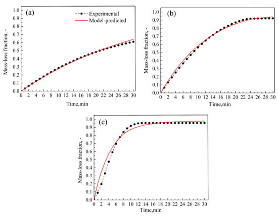
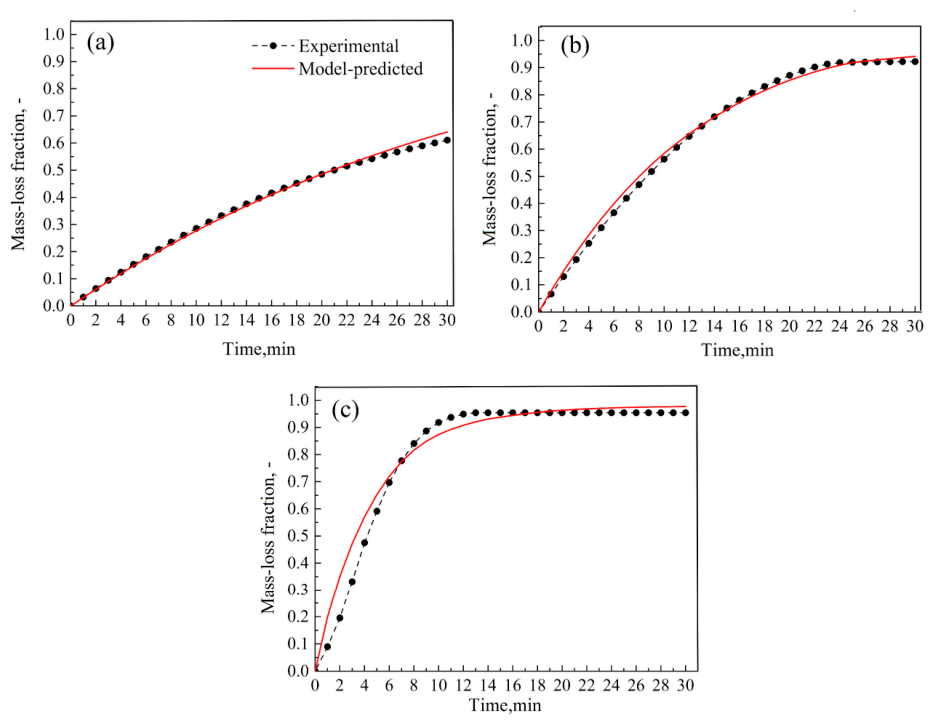
Under ags = 10 m2·m−3, the experimental and model-predicted mass-loss curves at different temperatures were compared, and the results are presented in Figure 2. The model predictions are in good agreement with the experimental results, indicating that the model accurately describes the mass-loss behavior under the investigated conditions.
Figure 2.
Comparison of the model-predicted and experimental mass-loss curves under different temperatures: (a) 1173 K, (b)1273 K, (c) 1373 K.
In addition to comparing the mass-loss curves, the final overall iron oxide reduction fraction and the final overall carbon gasification fraction were also compared, and the results are listed in Table 4. As shown in the table, the absolute error for each scenario is less than 5%, further demonstrating that the developed model was reliable.
Table 4.
Comparison of model-predicted and experimental reduction parameters of ICCB.
The above analysis indicates that the model is adequate for analysis of the ICCB reaction under the H2-H2O-N2 atmosphere.
4.2. Reaction Development Under Non-Isothermal Conditions
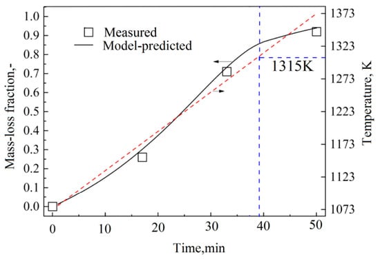
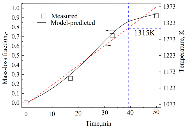
In BF ironmaking, ICCB is introduced alongside the iron-bearing burden, such as pellets or sinters. Consequently, the examination of the reduction behavior of ICCB under non-isothermal conditions is more practically relevant to BF ironmaking. Therefore, model simulation under the experimental non-isothermal conditions was conducted. The model-predicted mass-loss curve is shown in Figure 3. The experimentally measured mass-loss fractions are in close agreement with the model predictions, demonstrating further the reliability of the proposed model. Moreover, as shown in Figure 3, the ICCB exhibited a rapid mass loss at temperatures above 1298 K, followed by a slower mass-loss rate at higher temperatures.
Figure 3.
Model-predicted mass-loss curve under non-isothermal conditions.
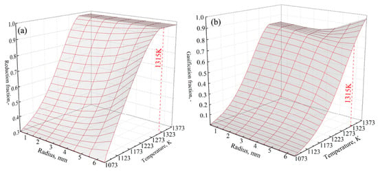
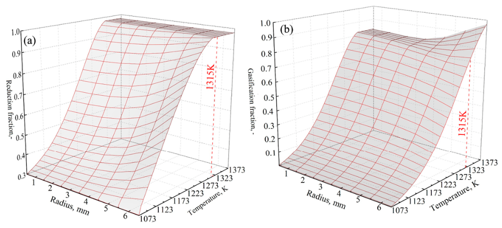
The model-predicted distributions of the local iron oxide reduction fraction and the local carbon gasification fraction along the radial direction at different temperatures are shown in Figure 4. Below 1315 K, reduction of iron oxide proceeded more rapidly near the periphery than near the center of the ICCB. In contrast, carbon gasification proceeded preferentially near the center. Above 1315 K, the iron oxide fines were almost completely reduced, while carbon gasification continued mainly near its periphery. Therefore, the slow mass loss of the briquette at higher temperatures was mainly attributed to the continued gasification of carbon in the peripheral area of the ICCB.
Figure 4.
Changes in radial distributions of local reduction fraction (a), and local carbon gasification fraction (b) with temperature.
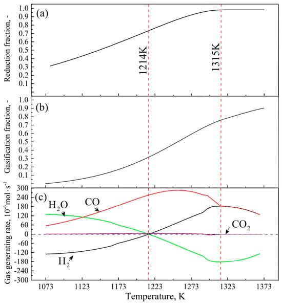
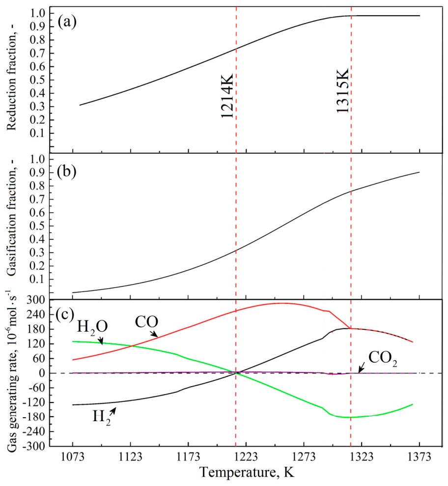
The model simulation results of the changes in overall reduction fraction with temperature are plotted in Figure 5a, the changes in the overall carbon gasification fraction in Figure 5b, and the changes in the generating rates of H2, H2O, CO, and CO2 in Figure 5c. Below 1214 K, the iron oxide exhibited a relatively uniform reduction rate, and the carbon exhibited a low gasification rate. In this stage, the ICCB consumed H2 from the environment and released H2O and CO to the environment. In the temperature range from 1214 K to 1315 K, the reduction of iron oxide became slow and the gasification of carbon became fast. In this stage, the ICCB consumed H2O from the environment and released H2 and CO to the environment. After the temperature reached 1315 K, the iron oxide was fully reduced and the only reaction in the ICCB was the gasification of carbon. Therefore, the ICCB consumed H2O from the environment and released H2 and CO into the environment at the same rate. Throughout the whole reduction process, the CO2 generating rate was negligibly low, indicating that the stepwise reduction of CO and the gasification of carbon by CO2 did not occur in the reduction process, and the main reactions in the ICCB reaction process are the stepwise reduction by H2 and the gasification of carbon by H2O.
Figure 5.
Development of the ICCB reaction process under non-isothermal conditions: (a) overall reduction fraction; (b) overall carbon gasification; (c) generating rates of gas species.
4.3. Metallurgical Properties Change Under Non-Isothermal Conditions
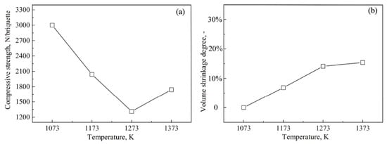
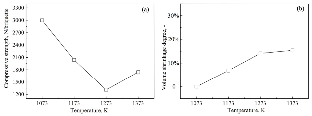
Under non-isothermal conditions, changes in the compressive strength of the ICCB were measured, and the results are shown in Figure 6a. The compressive strength exhibited a V-typed trend. It decreased from 3000 N/briquette to 1312 N/briquette as the temperature increased from 1073 K to 1273 K. However, above 1273 K, the compressive strength gradually increased, reaching 1742 N/briquette at 1373 K. The change in the volume shrinkage degree is shown in Figure 6b. The ICCB underwent continuous contraction as the temperature increased. In the temperature range from 1073 K to 1273 K, the volume shrinkage degree increased rapidly from 0 to 14%. The ICCB exhibited a very slow volume contraction above 1273 K, reaching a volume shrinkage degree of 15% at 1373 K.
Figure 6.
Change in compressive strength of ICCB (a) and volume shrinking degree of ICCB (b) with temperature.
4.4. Microstructure Evolution Under Non-Isothermal Conditions
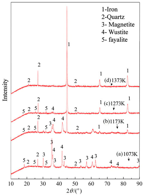
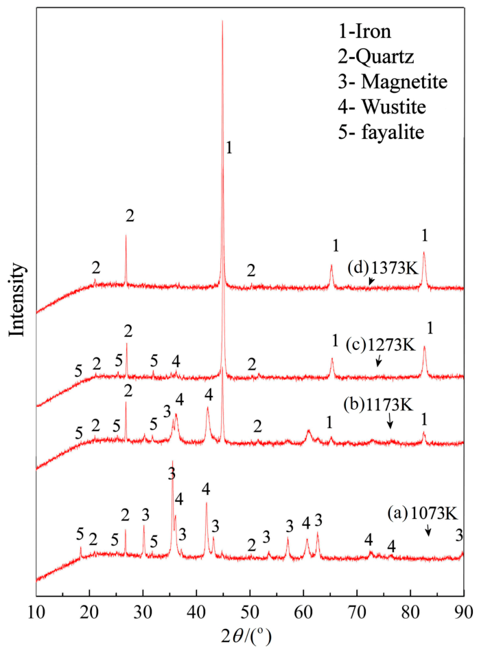
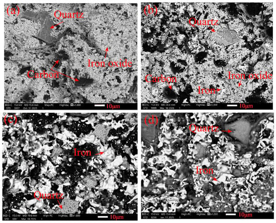
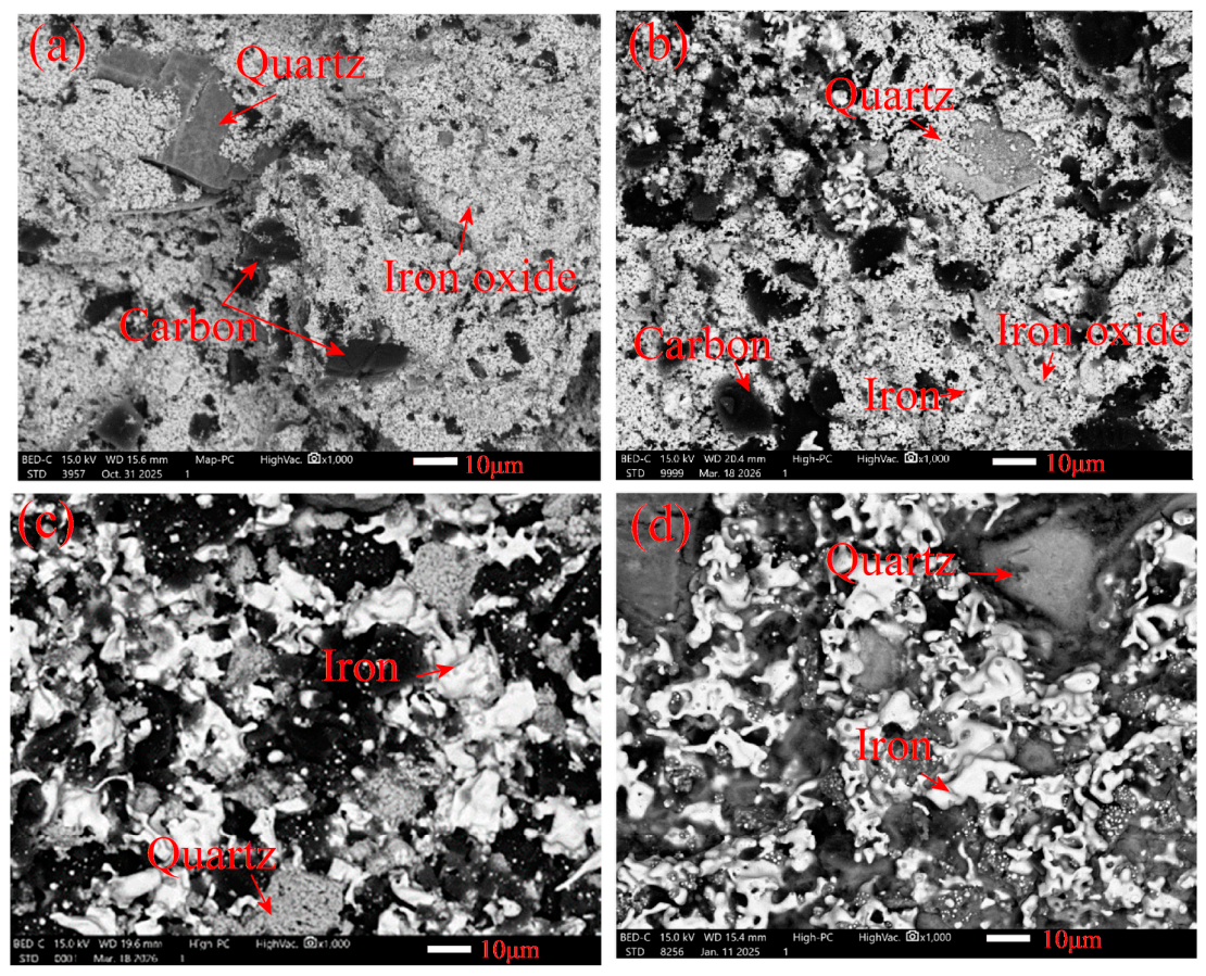
Under the non-isothermal experimental conditions, the microstructural evolution of the ICCB was investigated. Figure 7 shows the phase-composition evolution of the ICCB, and Figure 8 presents the morphological evolution near the center of the ICCB.
Figure 7.
XRD patterns at different temperatures.
Figure 8.
SEM Images of ICCB at different temperatures: (a) 1073 K, (b) 1173 K, (c) 1273 K and (d) 1373 K.
In Figure 7, the phase-composition development can be described as follows. In the initial state at 1073 K, the main phases were magnetite, wustite, quartz, and fayalite (Figure 7a). When the temperature reached 1173 K, the peaks of magnetite became weak, indicating that most of the magnetite was reduced to wustite; peaks of metallic iron became strong, indicating that metallic iron was generated in the briquette (Figure 7b). As the temperature increased to 1273 K, most of the iron oxides were reduced to metallic iron (Figure 7c). With the further increase in temperature, the fayalite gradually decomposed, and only metallic iron and quartz could be identified in the end (Figure 7d).
Figure 8 shows the morphology evolution near the center of the ICCB. Initially, the iron oxide in the ICCB exhibited a sintered matrix of iron oxide, with carbon and quartz particles embedded in the sintered bed (Figure 8a). At 1173 K, the sintered iron oxide structure became porous, and some fine iron grains appeared within the sintered matrix (Figure 8b). With the increasing temperature, more and more fresh iron grains were generated and they gradually agglomerated, resulting in the formation of iron particles with irregular shapes (Figure 8c). In the presence of H2, the hydrogen in the reducing agent has the effect of prompting the development of iron whiskers. At 1373 K, the iron whiskers gradually interconnected, forming an iron network within the ICCB (Figure 8d).
5. Conclusions
In the present research, the ICCB for BF ironmaking was prepared with a composition of 21.07 wt.% Fe3O4, 49.89 wt.% FeO,16.46 wt.% carbon, and 18.73 wt.% gangue. Its reaction behavior under the H2-H2O-N2 atmosphere was systematically investigated. The main conclusions are the following:
(1). Under ags = 10 m2 ⋅ m−3, the model predictions fitted the experimental results well, confirming its validity for the present research.
(2). In the ICCB reduction under non-isothermal conditions, the main reactions were the stepwise reduction by hydrogen and the carbon gasification by H2O, and the stepwise reduction by CO and carbon gasification by CO2 were negligible.
(3). Under non-isothermal conditions, the ICCB present a V-type change in compressive strength and the minimum compressive strength was 1274 N/briquette at 1273 K. The ICCB shows a successive shrinking as the temperature increased and the final volume shrinking degree was 0.15.
(4). Under non-isothermal conditions, the phase-composition evolution in ICCB included the conversion of iron oxides to metallic iron and the decomposition of fayalite, and the development of morphology in ICCB consisted of disintegration of the sintered matrix, formation of irregular iron grains, and the emergence of a metallic iron network.
Author Contributions
Conceptualization, H.T.; methodology, H.T.; software, Z.S. and H.T.; validation, Z.S. and X.Z.; formal analysis, Z.S.; investigation, Z.S. and X.Z.; resources, Z.S. and X.Z.; data curation, Z.S.; writing—original draft preparation, Z.S.; writing—review and editing, H.T.; visualization, Z.S. and X.Z.; supervision, H.T.; project administration, H.T.; funding acquisition, H.T. All authors have read and agreed to the published version of the manuscript.
Funding
This research was funded by the State Key Laboratory of Advanced Metallurgy, USTB under grant number of 41626010.
Data Availability Statement
The original contributions presented in this study are included in the article. Further inquiries can be directed to the corresponding author.
Acknowledgments
Financial support from the state key laboratory of advanced metallurgy, USTB is acknowledged.
Conflicts of Interest
The authors declare no conflict of interest.
References
- International Energy Agency. Iron and Steel Technology Roadmap: Towards More Sustainable Steelmaking; IEA: Paris, France, 2020. [Google Scholar] [CrossRef] [Scilit]
- International Energy Agency. Iron & Steel. Available online: https://www.iea.org/energy-system/industry/steel (accessed on 17 September 2026).
- Zhang, J.; Shen, J.; Xu, L.; Zhang, Q. The CO2 emission reduction path towards carbon neutrality in the Chinese steel industry: A review. Environ. Impact Assess. Rev. 2023, 99, 107017. [Google Scholar] [CrossRef] [Scilit]
- Chen, Y.; Fang, Y.; Feng, W.; Zhang, Y.; Zhao, G.X. How to minimize the carbon emission of steel building products from a cradle-to-site perspective: A systematic review of recent global research. J. Clean. Prod. 2022, 368, 133156. [Google Scholar] [CrossRef] [Scilit]
- Kasai, A.; Toyota, H.; Nozawa, K.; Kitayama, S. Reduction of reducing agent rate in blast furnace operation by carbon composite iron ore hot briquette. ISIJ Int. 2011, 51, 1333–1335. [Google Scholar] [CrossRef] [Scilit]
- Dutta, S.K. Iron ore-coal composite pellets/briquettes as new feed material for iron and steelmaking. Mater. Sci. Eng. Int. J. 2017, 1, 10–13. [Google Scholar] [CrossRef] [Scilit][Green Version]
- Bizhanov, A.M.; Zagainov, S.A. Use of ore-coal briquettes in blast furnaces. Metallurgist 2022, 66, 749–756. [Google Scholar] [CrossRef] [Scilit]
- Masuka, S.M.; Chiwandika, E.K.; Liu, H.; Gao, B. Advanced Applications of Self-Reducing Pellets for Low-Carbon Ironmaking: A Critical Review. J. Sustain. Metall. 2026, 12, 2450–2465. [Google Scholar] [CrossRef] [Scilit]
- Ren, J.; Xu, C.; Aisiaiti, C.; Ahmed, M.; Cao, S.; Lu, C.; Zhang, D.; Helle, M.; Yu, Y. Evolution and mechanistic study of hot compressive strength of cold-bonded iron ore briquettes during reduction under simulated blast furnace. Powder Technol. 2026, 479, 122529. [Google Scholar] [CrossRef] [Scilit]
- Yu, X.; Shen, Y. Computational fluid dynamics study of the flow and thermochemical behaviors of a carbon composite briquette in an ironmaking blast furnace. Energy Fuels 2019, 33, 11603–11616. [Google Scholar] [CrossRef] [Scilit]
- Bao, J.-W.; Chu, M.-S.; Liu, Z.-G.; Lv, W.; Han, D.; Zhang, L.F. Evolution behavior and mechanism of iron carbon agglomerates under simulated blast furnace smelting conditions. J. Iron Steel Res. Int. 2023, 30, 1714–1731. [Google Scholar] [CrossRef] [Scilit]
- Nomura, S. “COURSE50”—CO2 ultimate reduction system for cool earth 50: CO2 ultimate reduction in steelmaking process by innovative technology in Japan. In Treatise on Process Metallurgy; Elsevier: Amsterdam, The Netherlands, 2025; pp. 231–244. [Google Scholar] [CrossRef] [Scilit]
- Li, H.; Chen, J. An analysis of long-process ironmaking in a reduction smelting furnace with hydrogen-enriched conditions. Metals 2023, 13, 1756. [Google Scholar] [CrossRef] [Scilit]
- Lan, C.; Hao, Y.; Shao, J.; Zhang, S.; Liu, R.; Lyu, Q. Effect of H2 on blast furnace ironmaking: A review. Metals 2022, 12, 1864. [Google Scholar] [CrossRef] [Scilit]
- Shatokha, V. Injection of hydrogenous gases into the blast furnace tuyeres for reducing CO2 emissions: A review. ISIJ Int. 2024, 64, 1945–1955. [Google Scholar] [CrossRef] [Scilit]
- Ren, M.; Zhang, J.; Xu, R.; Hao, L.; Ji, H.; He, X.; Pei, Y.; Zhao, J. Comparative study on coke oven gas and refined hydrogen-rich gas injection in blast furnace: Effects on tuyere and raceway behavior. Metall. Mater. Trans. B 2025, 56, 197–211. [Google Scholar] [CrossRef] [Scilit]
- Mauret, F.; Baniasadi, M.; Saxén, H.; Feiterna, A.; Hojda, S. Impact of Hydrogenous Gas Injection on the Blast Furnace Process: A Numerical Investigation. Metall. Mater. Trans. B 2023, 54, 2137–2158. [Google Scholar] [CrossRef] [Scilit]
- Tang, H.; Sun, Y.; Rong, T.; Guo, Z. Reaction model and reaction behavior of carbon composite briquette in blast furnace. Powder Technol. 2021, 377, 832–842. [Google Scholar] [CrossRef] [Scilit]
- Chai, Y.; Wang, S.; Zhang, J.; Shi, Y.; Liu, P.; An, S.; Wang, C.; Ning, X. Study on strength and reduction characteristics of iron ore powder-green carbon composite briquettes. Fuel 2024, 377, 132741. [Google Scholar] [CrossRef] [Scilit]
- Gandra, B.F.; Oliveira, A.F.L.; Bagatini, M.C.; Osório, E. Iron ore-petcoke briquettes as complementary burden for blast furnaces. J. Mater. Res. Technol. 2025, 35, 1556–1564. [Google Scholar] [CrossRef] [Scilit]
- Chang, H.H.; Chen, I.G.; Lu, K.M.; Liu, S.H. Effect of heating rate on carbothermic reduction and melting behavior of iron ore-coal composite pellets. ISIJ Int. 2021, 61, 2715–2723. [Google Scholar] [CrossRef] [Scilit]
- Zhi, Y.; Liu, Z.; Tang, H.; Xue, Q. Preparation of high-strength biochar composite briquette for blast furnace ironmaking. Metall. Res. Technol. 2021, 18, 109. [Google Scholar] [CrossRef] [Scilit]
- Zhang, T.; Liu, Y.; Tang, H. Reaction behavior of biochar composite briquette under H2-N2 atmosphere: Experimental study. Metals 2025, 15, 236. [Google Scholar] [CrossRef] [Scilit]
- Tang, H.; Guo, Z.; Kitagawa, K. Simulation study on performance of z-path moving-fluidized bed for gaseous reduction of iron ore fines. ISIJ Int. 2012, 52, 1241–1249. [Google Scholar] [CrossRef] [Scilit]
- Tanner, J.; Bhattacharya, S. Kinetics of CO2 and steam gasification of Victorian brown coal chars. Chem. Eng. J. 2016, 285, 331–340. [Google Scholar] [CrossRef] [Scilit]

Disclaimer/Publisher’s Note: The statements, opinions and data contained in all publications are solely those of the individual author(s) and contributor(s) and not of MDPI and/or the editor(s). MDPI and/or the editor(s) disclaim responsibility for any injury to people or property resulting from any ideas, methods, instructions or products referred to in the content. |
© 2026 by the authors. Licensee MDPI, Basel, Switzerland. This article is an open access article distributed under the terms and conditions of the Creative Commons Attribution (CC BY) license.