


Abstract
Flow characteristics constitute a fundamental factor governing the metallurgical performance of a tundish. The flow behavior of molten steel directly determines the floating removal efficiency of inclusions, the occurrence of slag entrainment, and the uniformity of flow distribution among multiple strands, which ultimately exerts a decisive influence on the quality of the final cast slab. The core objective of flow control device design is precisely to regulate tundish flow characteristics to meet metallurgical requirements. This work investigates the design of flow control devices for multi-strand tundishes and adopts a combined research scheme of numerical simulation and hydraulic physical experiment to systematically analyze the influence of the internal porous baffle structure on the flow characteristics of the tundish. The research indicates that the two research methods have complementary advantages: hydraulic physical simulation can obtain refined flow field information, while numerical simulation can intuitively capture the distribution rules of temperature field and overall flow pattern. The introduction of flow control devices with a porous baffle structure into the tundish can induce more directional circulating flow in the casting region, thereby effectively suppressing the occurrence of short-circuit flow. The regulation effect of different porous baffle schemes on tundish flow is essentially determined by the diameter and arrangement position of the openings on the baffle. In this study, both U-shaped and V-shaped baffles were adopted to reconstruct the internal flow structure of the six-strand tundish by adjusting the direction of the inlet jet and the distribution path of molten steel, which provides a fundamental reference for improving the flow consistency among different strands of the tundish.
1. Introduction
The tundish is an important link between the ladle and the mold in the continuous casting process. In addition to receiving and distributing molten steel, it promotes the flotation of non-metallic inclusions through an appropriate flow state and helps maintain stable casting operation [1]. The flow of molten steel also affects temperature-field uniformity; therefore, the flow field inside the tundish is a key factor governing the stability of continuous casting [2].
In a multi-strand tundish, differences in the spacing between strand regions, end-wall confinement, and flow distribution near the outlets lead to differences in flow deflection, recirculation, and velocity decay. The tundish geometry and flow-control devices jointly determine the flow paths and local residence characteristics of molten steel [3,4]. Consequently, optimizing the flow field of a multi-strand tundish by installing different flow-control devices is a central task in tundish design.
To improve flow conditions in different regions, a turbulence inhibitor is commonly installed beneath the ladle shroud. Its configuration affects jet spreading in the impact zone and the velocity distribution near the tundish bottom [5]. To further regulate the flow field, baffle walls and other flow-control devices can be arranged between the impact zone and the casting zone. These devices alter the flow path after the molten steel enters the casting zone and weaken the short-circuit flow directed from the bottom toward the submerged entry nozzles [6]. For perforated or channel-type structures, their primary effects are reflected in changes in the downstream flow direction and local velocity distribution [7]. In a six-strand tundish, a U-shaped baffle wall can guide the molten steel through the channels to form a relatively well-defined lateral jet, whereas a V-shaped baffle wall causes the incoming flow to converge in front of the baffle wall and then spread toward both sides. The local jet patterns generated by the two baffle-wall configurations differ, and their flow paths and velocity-decay characteristics therefore require further analysis.
Recent studies have mainly examined the effects of dams, weirs, and side-wall inclination on molten-steel flow and inclusion removal [8,9], as well as the flow-control performance of stopper rods, ladle shrouds, and turbulence inhibitors [10,11,12]. Numerical simulations and PIV experiments have also been used to validate the flow field [13]. In addition, changes in the flow field, temperature field, and flow symmetry of multi-strand tundishes have been analyzed under conditions where some outlets were shut off while casting continued through the remaining outlets [14].
Water model experiments can directly reveal local flow behavior inside a tundish, while particle image velocimetry (PIV) provides velocity information for tracer particles within the measurement plane and is suitable for identifying flow characteristics [15]. Numerical simulation can provide the velocity field, temperature field, and streamline distribution throughout the computational domain, thereby describing the overall flow path of the inlet jet after it passes through the flow-control device [16]. Previous studies have shown that physical modeling and numerical simulation can reveal tundish flow characteristics at different spatial scales [17]. Therefore, examining the local flow field using PIV experiments together with the overall flow field obtained from numerical simulation is useful for analyzing changes in molten-steel flow paths caused by different baffle-wall configurations.
This study addressed the short molten-steel flow paths in strands 3 and 4, the long flow paths in strands 1 and 6, and the flow-direction change at the T-shaped outlets of a six-strand tundish. Perforated U-shaped and V-shaped dams were installed in the tundish to clarify the characteristics of jet splitting, velocity attenuation, and side-wall recirculation downstream of the dam openings, and to examine the effects of dam geometry on the molten-steel flow behavior in the six-strand tundish. Computational Fluid Dynamics (CFD) simulations and water model experiments were conducted to relate the molten-steel flow paths downstream of the dam openings to the residence time distribution (RTD) characteristics of the individual strands. The analysis aimed to reduce excessive impingement of molten steel on the stopper rods and side walls and to prevent excessively rapid responses among the strands, thereby revealing the complex flow-field characteristics in the coupled regions affected by the post-opening jets, the stopper rods, and the tundish side walls. The findings provide a basis for the targeted structural design and comprehensive evaluation of the dams to improve the overall flow performance and strand-to-strand consistency.
2. Mathematical Model of Flow in the Tundish
2.1. Research Object
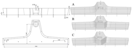
A six-strand tundish from a steel plant was selected as the prototype, and several perforated dam configurations were designed based on its internal dimensions, as shown in Figure 1. The three flow-control schemes used in the numerical simulations were designated as Cases A, B, and C, as listed in Table 1. A physical model was constructed according to the structural dimensions, stable liquid level, ladle-shroud parameters, casting throughput, and other design and process parameters. A water model was then developed using a prescribed similarity ratio, and its detailed dimensions are provided in Table 2.
Figure 1.
Geometric dimensions of the six-strand tundish and schematic diagrams of the three flow-control cases: (A) empty tundish; (B) U-shaped perforated baffle wall; (C) V-shaped perforated baffle wall.All dimensions are in millimeters (mm).
Table 1.
Computational schemes for the tundish.
Table 2.
Geometric parameters of the six-strand tundish.
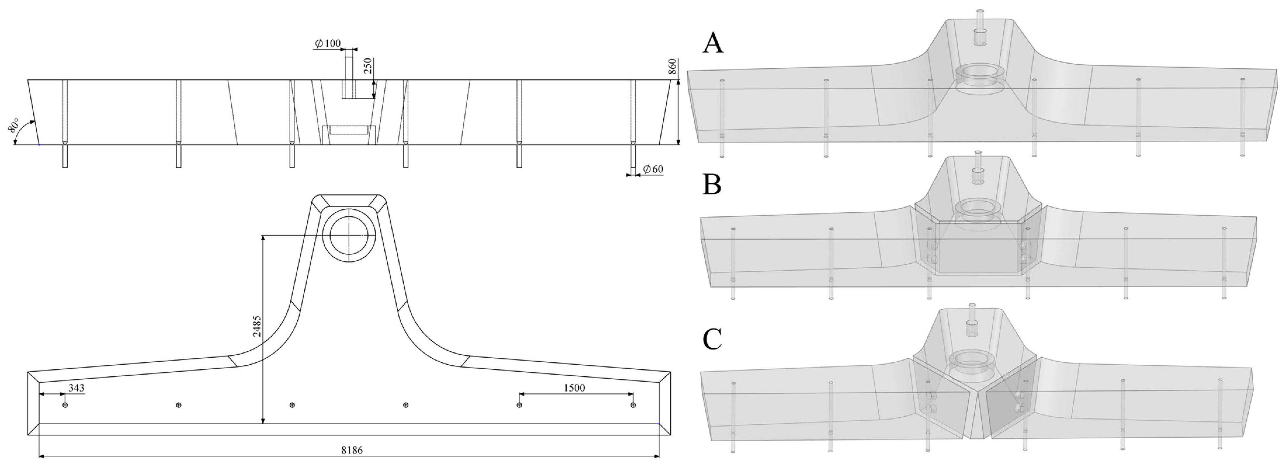
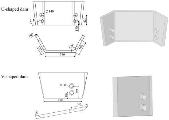
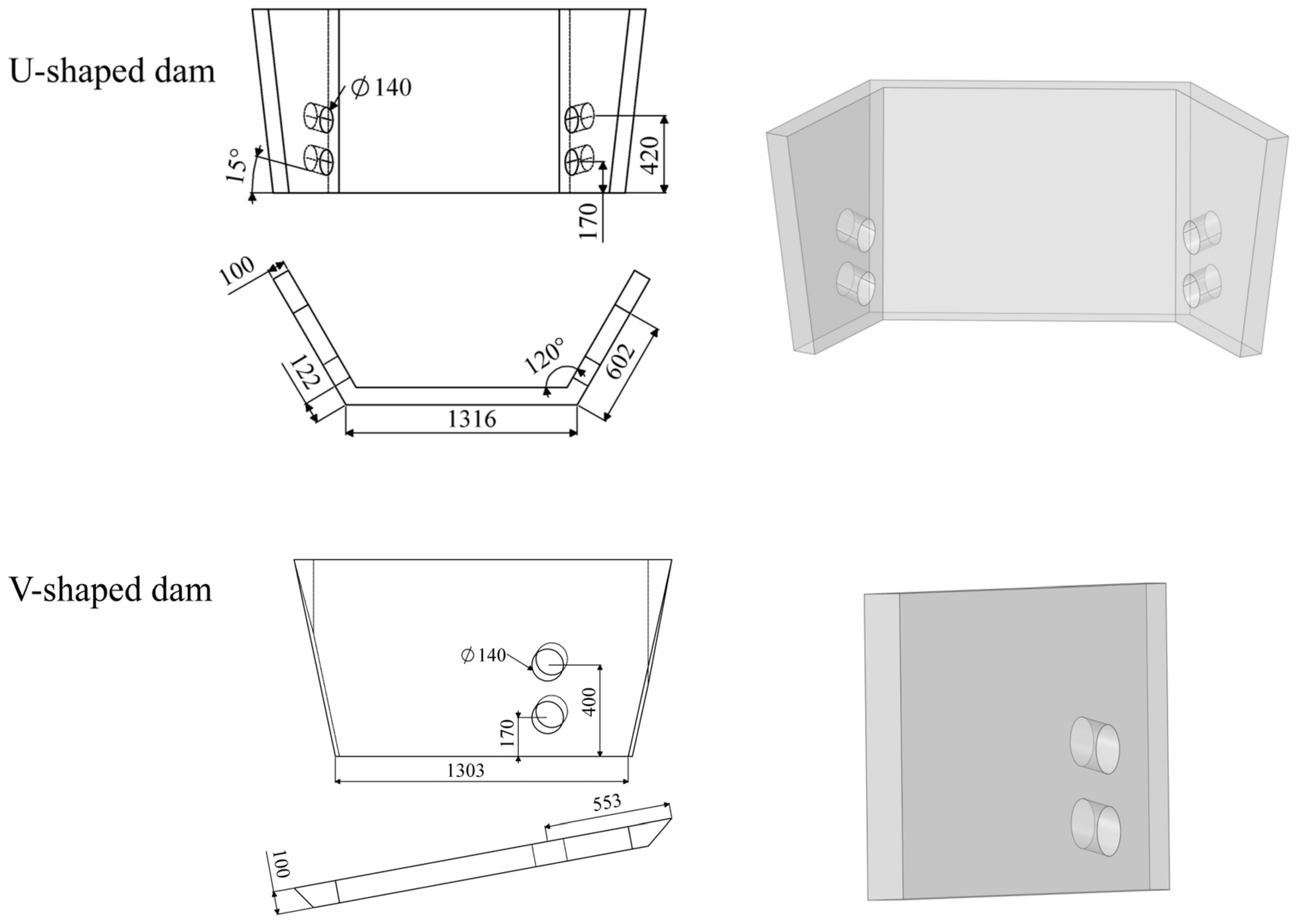
The hole diameter was set to 140 and the hole inclination angle to 15° to control the impact intensity and propagation direction of the molten-steel jets. At a given casting rate, an excessively small hole diameter would increase the flow velocity within the holes, intensify jet impingement on the side walls, and potentially extend the impact region toward the stopper rods, thereby disturbing the flow near the stopper rods. A hole diameter of 140 was therefore selected to alleviate these effects. The hole inclination angle was chosen by considering both liquid-level stability and the response of the individual strands. An excessively large angle could cause the jet to emerge from the liquid surface and induce liquid-level disturbance. Accordingly, a 15° inclination angle was adopted to limit jet-induced disturbance at the liquid surface and moderately slow the multi-strand response. The detailed dam parameters are shown in Figure 2.
Figure 2.
Geometric parameters of the U-shaped and V-shaped dams.All dimensions are in millimeters (mm).
2.2. Basic Assumptions
A three-dimensional computational model was established for molten-steel flow in an actual six-strand tundish. The flow-control devices, working liquid level, inlet velocity, and outlet boundary conditions were specified according to the respective cases [18]. Considering the flow and temperature distribution investigated in this study, the continuity, momentum, energy, and turbulence-model equations were established under steady-state and incompressible-flow assumptions [19].
(1) The molten-steel flow in the tundish was assumed to be steady, and the flow-field parameters were assumed to remain unchanged with time.
(2) Molten steel was assumed to be incompressible, and density variations caused by temperature gradients or compositional segregation were neglected.
(3) The effects of temperature variation on the physical properties of molten steel, such as density and viscosity, were neglected, and these properties were assumed to remain constant.
(4) Heat transfer in the tundish was treated as a three-dimensional steady-state process.
2.3. Governing Equations and Boundary Conditions
The flow and temperature distribution of molten steel in the tundish were described by the continuity, momentum, and energy equations, respectively. The turbulence parameters were calculated using the standard model. The governing equations are given below [20].
The continuity and momentum equations are expressed as follows [21]:
where is the resultant fluid velocity (); is the fluid density (); is time (); is the dynamic viscosity of the fluid (); is the static pressure, ; and is the gravitational acceleration ().
The turbulent flow of molten steel in the tundish was described using the standard model.
where represents the generation of turbulent kinetic energy due to the mean velocity gradient; is the turbulent kinetic energy (); is the turbulent dissipation rate (); and is the turbulent viscosity (), calculated as:
where , , , ,
The energy transport equation is given as follows [22]:
where is the enthalpy of molten steel (); is the molten-steel temperature (); and is the effective thermal conductivity ().
The overall mesh size in the computational domain was set to 25 . Local mesh refinement was applied to the ladle shroud, dam openings, and the regions around the six submerged entry nozzles, with five refinement layers. The mesh quality was checked and found to satisfy the requirements of the numerical calculations. A mesh-independence analysis was performed, and approximately 6–7 million cells were finally used. Once the cell number reached this range, the relative differences in the key calculated results remained below 5.
The computational domain comprised the molten-steel flow region of the six-strand tundish, including the tundish body, ladle shroud, flow-control devices, stopper rods, and six submerged entry nozzles. The inlet velocity of the ladle shroud was determined from the maximum prototype casting rate, molten-steel density, and ladle-shroud cross-sectional area according to mass conservation. The prototype casting rate was 4.7 , the ladle-shroud inner diameter was 100 , the molten-steel density was set to 7020 , and the dynamic viscosity was set to 0.0067 . Both properties were treated as constant throughout the computational domain and independent of temperature [23]. A velocity-inlet boundary condition was imposed at the ladle-shroud inlet, with an inlet velocity of 1.43 . The inlet turbulent kinetic energy and turbulent dissipation rate were set to 0.00767 and 0.0158 , respectively. Outflow boundary conditions were applied at the six submerged entry nozzles. No-slip wall conditions were imposed on the tundish bottom, tundish walls, ladle-shroud wall, and flow-control-device surfaces. At the top of the computational domain, the reference shear stress and wall roughness were both set to zero, and the surface was treated at the stable design liquid level of the tundish. Liquid-level fluctuation and the effects of the cover flux and slag layer on the flow field were neglected. For the temperature-field calculation, a constant heat flux of 15 was imposed on the upper surface, while constant heat fluxes of 3.8 were imposed on both the bottom surface and the side walls.
The flow velocity and temperature field inside the tundish were simulated using Fluent (2022). Based on the three cases described above, a geometrically scaled water model was constructed, and quantitative velocity measurements were conducted using particle image velocimetry (PIV). The flow fields obtained from the two methods were then compared.
3. Construction of the Water Model Experimental Facility and PIV Measurements
3.1. Principles of Water Modeling and Experimental Facility
The water model experiment was based on the similarity principle, which requires geometric and dynamic similarity between the prototype and the model [24]. Geometric similarity means that the ratio of corresponding geometric dimensions of the model and prototype remains constant. In this study, the geometric similarity ratio was 1:2.5, meaning that each dimension of the water model was 0.4 times the corresponding dimension of the prototype:
where is a geometric dimension (); the subscripts and denote the model and prototype, respectively; and is the geometric similarity ratio.
Because the fluid flow in both the prototype and the model was turbulent, the Reynolds number and Froude number were calculated using the inner diameter of the ladle shroud as the characteristic length, as shown below. Ensuring that the Froude numbers () of the model and prototype are equal satisfies the requirement for dynamic similarity [25].
where is the fluid density (); is the inner diameter of the ladle shroud (); μ is the dynamic viscosity (); is the gravitational acceleration (9.81 ); is the fluid velocity (); and is the fluid flow rate in the tundish ().
The calculated Reynolds numbers of the prototype and water model were and , respectively. Although the two values were not identical, both flows were turbulent; therefore, Reynolds-number similarity was not imposed. Since the macroscopic flow of molten steel in the tundish is governed mainly by inertial and gravitational forces, the Froude-number similarity criterion was adopted as the primary basis for designing the water model [26]. Maintaining equal Froude numbers between the prototype and water model therefore provides the required similarity for investigating the macroscopic flow characteristics.
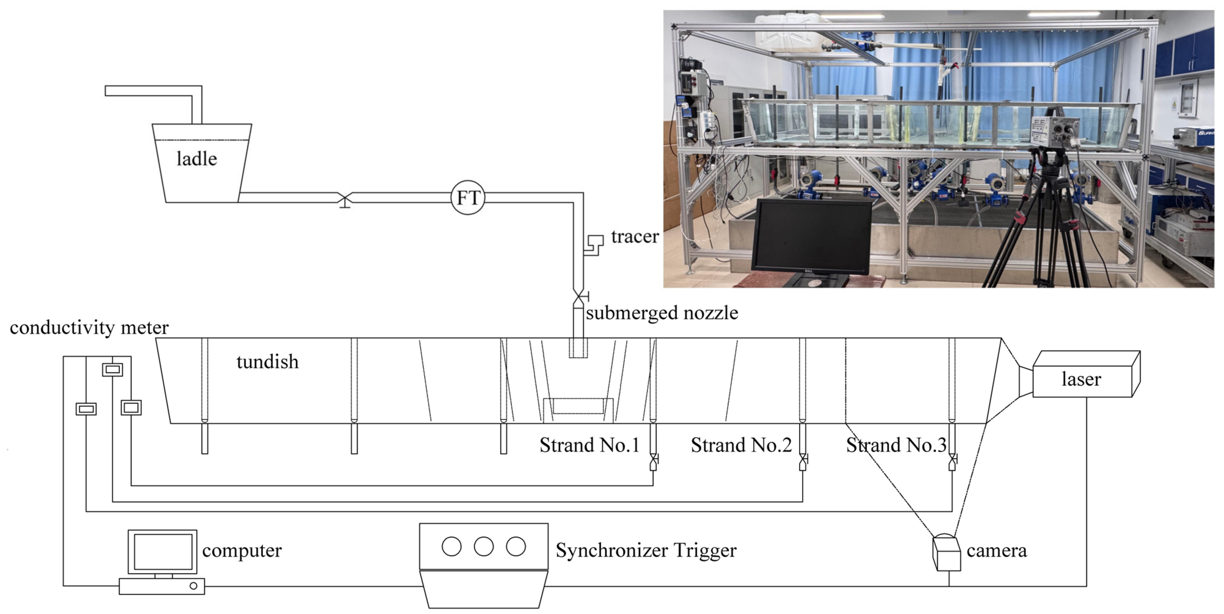
Based on the similarity relationships described above, the water model experimental parameters were determined from the operating conditions of the prototype tundish. The model working liquid level was 344 ; the total inlet flow rate was 68.2 ; the inner diameter of the ladle shroud was 40 ; the flow rate at each of the six outlets was 11.36 , the strand spacing was 600 , and the outlet inner diameter was 24 . The water model experimental facility is shown in Figure 3.
Figure 3.
Schematic of the six-strand tundish water model experimental platform.
3.2. PIV Measurement Method
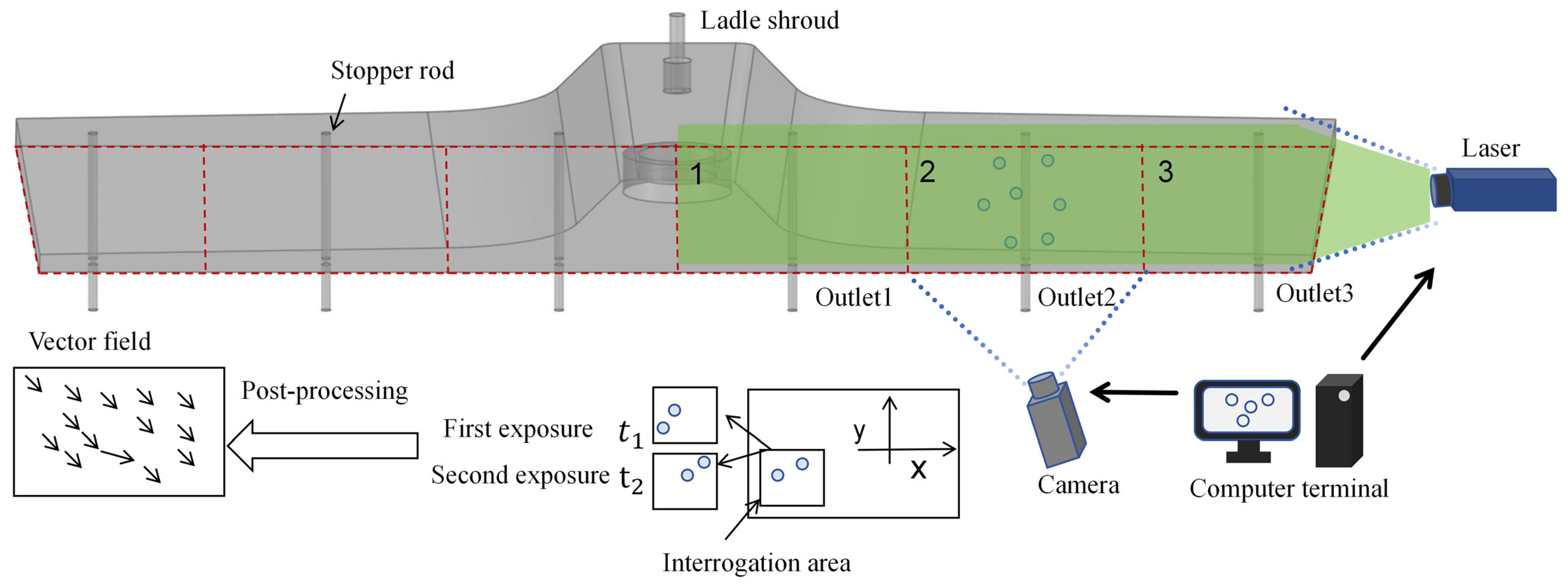
The PIV system consisted of a pulsed laser (Darwin-Duo-527-80-M, Beiting Measurement Technology (Beijing) Co., Ltd., Beijing, China; wavelength: 527 ; average power: 80 ), a Fastcam SA3 high-speed camera(Photron Ltd., Tokyo, Japan), tracer particles, a synchronization unit, and PIVlab(2022) image-processing software. The system was used to measure the velocity field in the tundish. The camera sensor resolution was 1024 × 1024 pixels, and images were acquired at 50 with an electronic shutter time of up to 2 . The laser pulse duration was less than 230 , enabling clear imaging of the flow. During the experiments, the laser illuminated the measurement plane, while the camera, triggered by the synchronization unit, recorded the motion of the tracer particles. The particle displacements between consecutive images were calculated using the cross-correlation method in PIVlab to obtain the two-dimensional velocity vector field in the measurement plane [27,28]. Polystyrene spheres with a mean density of 1.03 and a diameter of 50–100 were used as tracers. Before each experiment, the particles were mixed with pure water and introduced into the water model through the ladle shroud, allowing them to disperse with the flow. Their flow-following and light-scattering properties were suitable for flow-field imaging.
Before each experiment, the flow-control devices were installed, the inner walls of the model were cleaned, and the piping was checked for leaks. The circulating water system was then started, and the liquid level and inlet and outlet flow rates were adjusted to the prescribed conditions. Once the flow had stabilized, the pre-dispersed tracer particles were added. The distance between the camera and the water model was adjusted according to the dimensions of the measurement window so that the entire target region fell within the camera’s field of view and occupied as much of the effective imaging area as possible, without truncating the measurement boundaries. Because the camera field of view was limited, the flow field of the six-strand tundish was measured using separate observation windows. The same measurement window was fixed for each acquisition, and images were repeatedly collected under different operating conditions. The flow-field characteristics in the casting zone were then obtained by stitching the measured windows together, as illustrated in Figure 4.
Figure 4.
Flowchart of the PIV measurement procedure.
4. Analysis and Comparison of Results
The flow field and temperature-field characteristics inside the tundish were obtained using Fluent, and the corresponding streamline distributions were also determined.
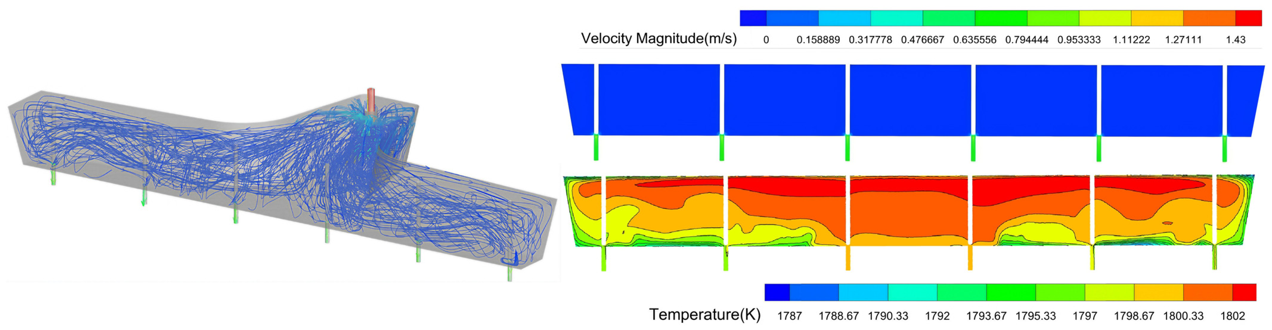
Figure 5 shows the flow field in the tundish without a perforated baffle-wall flow-control device. Molten steel discharged from the ladle shroud impinged on the turbulence inhibitor. After dissipation of turbulent kinetic energy, the flow spread through the open arms of the T-shaped tundish toward the six outlets. The outlets near the middle of the tundish had shorter flow paths, whereas the two end outlets were farther from the ladle shroud, resulting in considerable differences in flow consistency among the six outlets. The calculated velocity throughout the casting zone was relatively uniform, with an average value of 0.02–0.03. The temperature difference between the two ends of the tundish was 15. The streamlines show that molten steel reached the casting zone rapidly after passing through the turbulence inhibitor in the central region, whereas the steel flowing toward the end regions turned along the bottom and end walls before reaching the outlets, with local recirculation occurring near the end walls. The temperature field was characterized by higher temperatures in the upper region and lower temperatures near the bottom and end walls; the temperature decrease was more pronounced near the ends. Thus, under the empty-tundish condition, the inlet jet was not laterally constrained, resulting in differences in the flow paths and temperature conditions among the strands.
Figure 5.
Flow and temperature fields of molten steel in the six-strand tundish under Case A (empty tundish).
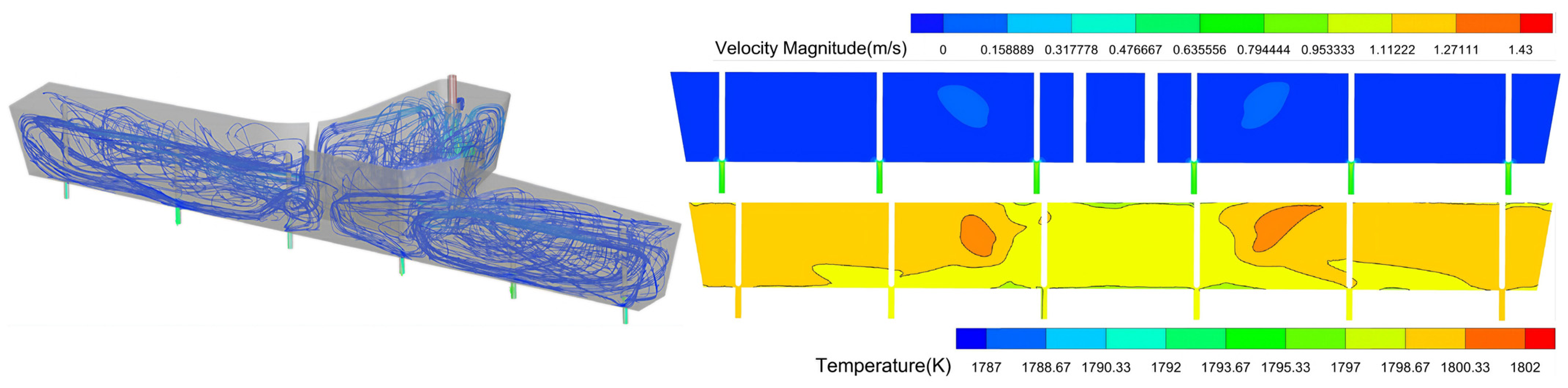
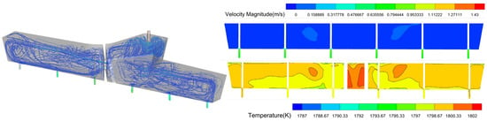
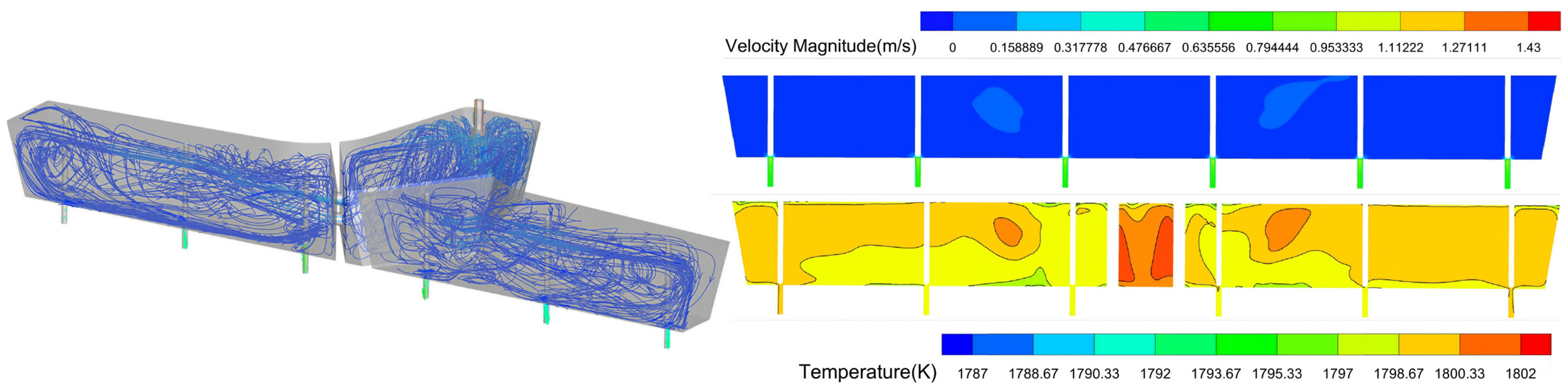
Figure 6 and Figure 7 show the flow characteristics produced by two perforated baffle-wall configurations in the tundish. Figure 6 corresponds to the U-shaped baffle wall, whereas Figure 7 corresponds to the V-shaped baffle wall. With the U-shaped baffle wall, molten steel can be exchanged among the six outlets in the casting zone. With the V-shaped baffle wall, the two arms of the T-shaped tundish are separated, and no flow exchange occurs between the left and right sides.
Figure 6.
Molten-steel flow and temperature fields in the six-strand tundish under numerical simulation Case B.
Figure 7.
Molten-steel flow and temperature fields in the six-strand tundish under numerical simulation Case C.
Comparison of the two configurations shows that the turbulent flow generated after the molten steel passes through the turbulence inhibitor is largely confined to the impact zone. The molten steel then enters the casting zone through the inclined openings in the baffle wall. In this study, the openings were inclined upward at 15 , allowing a large recirculation zone to develop rapidly in the casting zone. The jet impingement region was close to the free surface, but its effect on the free surface was not significant.
The figures also show that the temperature difference among the six outlets was smaller with the baffle wall than in the empty tundish. Based on these flow characteristics, the main difference among Cases A, B, and C lies in the flow-distribution path from the inlet to the casting zone. In Case A, the flow toward the outlets depended mainly on natural spreading after the inlet jet turned along the tundish bottom, resulting in considerable differences between the near and far outlets. In Case B, the two side channels of the U-shaped baffle wall provided flow passages for exchange between the left and right casting zones. The mean velocity at the channel cross-section was approximately 0.365 , decreasing to about 0.114 downstream of the openings as the jet momentum gradually dissipated along the casting zone. In Case C, the V-shaped baffle wall generated separate recirculating flows on the two sides. The downstream velocity was approximately 0.114 and decreased to about 0.057 as the flow spread outward, with limited exchange across the central region. Thus, the U-shaped configuration promotes flow exchange among the six outlets, whereas the V-shaped configuration maintains relatively independent recirculating flow on the two sides.
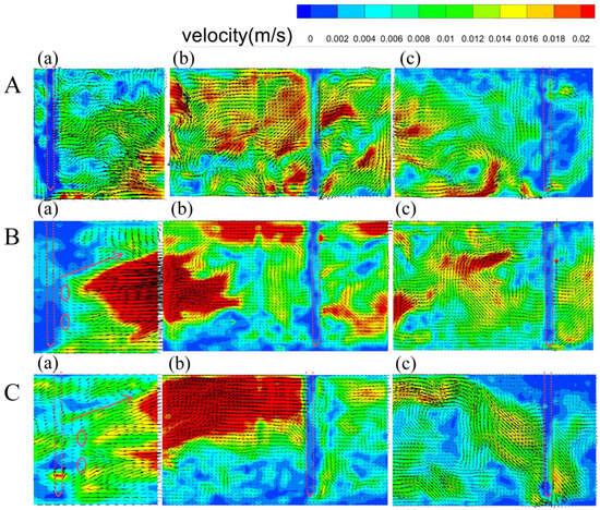
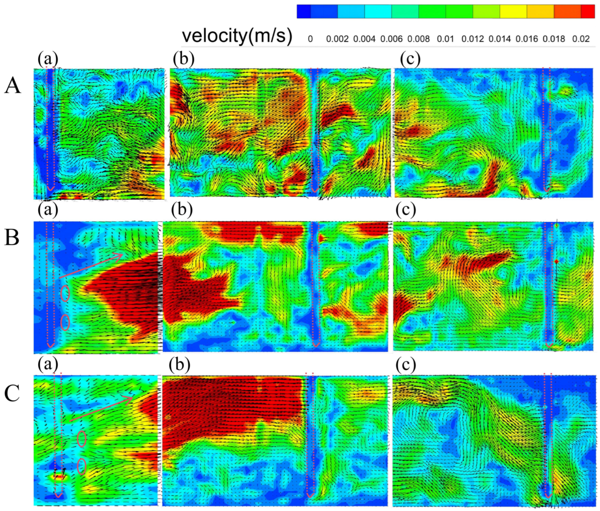
Figure 8 presents the velocity fields in the measured region, namely, the right arm of the tundish, obtained using PIV. The color scale represents velocity magnitude, while the arrows indicate flow direction. The relative positions of the stopper rods on the measurement planes are also marked for clarity. In Case A, the flow in this region moves directly from the inlet toward the outlets. In Cases B and C, the flow in the casting zone is mainly governed by the position, size, and inclination of the openings in the baffle wall.
Figure 8.
PIV-measured velocity fields in the right half of the six-strand tundish under different flow-control conditions: (a) viewing window 1, (b) viewing window 2, and (c) viewing window 3. The circles indicate the diversion holes.
Comparison of the numerical and measured flow fields shows that both methods reveal the flow characteristics inside the tundish. The numerical results provide a clearer description of the macroscopic flow pattern, whereas the PIV measurements reveal finer structures, including the distribution of vortices, and demonstrate the complexity of the flow.
Panel A shows the flow field without a flow-control device. No stable recirculation zone was formed in the tundish, and each outlet was supplied directly by the inlet flow. The overall velocity was lower near the end outlets. Panels B and C show the flow fields with perforated baffle walls. A large recirculation zone formed in the casting zone, but its structure differed from that predicted by the numerical simulation. The PIV measurements revealed multiple levels of vortical structures within the large recirculation zone. These vortices are important for the metallurgical functions of the tundish: the large-scale circulation promotes uniform flow distribution among the outlets, while the smaller vortices enhance inclusion collision and coalescence and promote inclusion removal through Stokes flotation. Compared with the U-shaped baffle wall, the V-shaped baffle wall caused stronger impact on the free surface because of its geometric position, and the flow distribution was less uniform. Therefore, the U-shaped perforated baffle wall is recommended as the flow-control device for the tundish.
Overall, the empty tundish was dominated by natural spreading; the U-shaped baffle wall produced relatively concentrated jets toward both sides, whereas the V-shaped baffle wall caused earlier jet splitting and more extensive lateral spreading. Both the numerical simulation and PIV measurements showed that the two baffle-wall configurations altered the inlet-jet path, avoided the central stopper-rod region, and generated continuous recirculating flow in the casting zone. The resulting complex flow provides the basic conditions for the tundish to perform its metallurgical functions.
5. Conclusions
Flow in the tundish was simulated using the standard turbulence model, and a reduced-scale water model was designed according to Froude-number similarity. Numerical simulations and PIV measurements were conducted for three configurations: a tundish without a dam and tundishes equipped with U-shaped and V-shaped dams. The flow field, temperature field, local velocities, and flow paths were characterized, and the effects of dam geometry on inlet-jet distribution and recirculating flow in the casting region were analyzed. The planned research objectives were largely achieved.
(1) Both methods revealed the flow details inside the tundish. The numerical simulation showed the macroscopic flow trend, whereas the water model experiment revealed the complex local flow structures. The perforated baffle walls generated a large recirculation zone in the casting zone. Both configurations directed the inlet jet toward both sides and avoided impact on the stopper rods. The U-shaped baffle wall produced more concentrated side jets, while the V-shaped baffle wall caused more pronounced lateral spreading after flow splitting.
(2) The numerical simulation showed that the mean velocity over the U-shaped channel cross-section was approximately 0.365 and decreased to 0.114 after the flow left the channel and entered the surrounding flow region. The PIV measurements also showed that the fluid rapidly spread after traveling 200–300 downstream of the perforated baffle-wall channel, with the velocity decreasing by more than 50.
(3) The U-shaped baffle wall promoted more extensive mixing of molten steel in the casting zone than the V-shaped baffle wall. Therefore, the U-shaped perforated baffle wall is recommended as the flow-control device for the six-strand tundish.
This study examined a tundish flow-control configuration already in use at an industrial plant and verified the suitability of the flow-control device design for production.
Author Contributions
Conceptualization, Y.Z. (Yazhu Zhang) and J.H.; Methodology, Y.Z. (Yinbo Zhao) and Y.Z. (Yazhu Zhang); Validation, R.S. and F.G.; Formal Analysis, Y.Z. (Yazhu Zhang) and S.Z.; Investigation, Y.Z. (Yinbo Zhao), R.S. and F.G.; Data Curation, Y.Z. (Yinbo Zhao); Writing—Original Draft Preparation, Y.Z. (Yinbo Zhao) and J.H.; Writing—Review and Editing, R.S., F.G., Y.Z. (Yazhu Zhang), S.Z. and J.H.; Visualization, Y.Z. (Yinbo Zhao), Y.Z. (Yazhu Zhang) and S.Z.; Supervision, Y.Z. (Yazhu Zhang) and J.H.; Funding Acquisition, S.Z. All authors have read and agreed to the published version of the manuscript.
Funding
This research received funding from China National Heavy Machinery Research Institute Co., Ltd. The authors declare that the funder was not involved in the study design, collection, analysis, interpretation of data, the writing of this article, or the decision to submit it for publication.
Data Availability Statement
The original contributions presented in this study are included in the article. Further inquiries can be directed to the corresponding author.
Conflicts of Interest
Author Kai Shi Zhou was employed by China National Heavy Machinery Research Institute Co., Ltd. The remaining authors declare that the research was conducted in the absence of any commercial or financial relationships that could be construed as a potential conflict of interest.
References
- Warzecha, M.; Merder, T.; Pfeifer, H.; Pieprzyca, J. Investigation of Flow Characteristics in a Six-Strand CC Tundish Combining Plant Measurements, Physical and Mathematical Modeling. Steel Res. Int. 2010, 81, 987–993. [Google Scholar] [CrossRef] [Scilit]
- Li, Y.; Hu, X.; Wang, L.; Zhang, H.; He, Y.; Zhang, W.; Hua, C. Numerical and experimental studies on the effects of molten steel viscosity on fluid flow, inclusion motion, and temperature distribution in a tundish. Phys. Fluids 2024, 36, 073102. [Google Scholar] [CrossRef] [Scilit]
- Merder, T.; Warzecha, M. Optimization of a Six-Strand Continuous Casting Tundish: Industrial Measurements and Numerical Investigation of the Tundish Modifications. Metall. Mater. Trans. B 2012, 43, 856–868. [Google Scholar] [CrossRef] [Scilit]
- Wu, D.; Liu, J.; Wu, D.; Zhou, P. Evaluation of Molten Steel Flow Behaviors in a Multistrand Tundish via Numerical Simulation and Grey Relational Analysis with a New Dimensionless Operator. Steel Res. Int. 2024, 95, 2300336. [Google Scholar] [CrossRef] [Scilit]
- Guarneros, J.; Morales, R.D.; Gutierrez, E. Optimized Fluid Flow Control System for a Tundish Used in Frequent Steel Grade Change Operations. Steel Res. Int. 2023, 94, 2200809. [Google Scholar] [CrossRef] [Scilit]
- Li, Q.; Qin, B.; Zhang, J.; Dong, H.; Li, M.; Tao, B.; Mao, X.; Liu, Q. Design Improvement of Four-Strand Continuous-Casting Tundish Using Physical and Numerical Simulation. Materials 2023, 16, 849. [Google Scholar] [CrossRef] [Scilit] [PubMed]
- Ding, G.; Feng, D.; Luo, X.; Hou, Q.; Lv, A.; Qi, X.; Qi, D. Numerical simulation study on the influence of tundish filter on molten steel flow and inclusions removal. Steel Res. Int. 2024, 95, 2300807. [Google Scholar] [CrossRef] [Scilit]
- Mostafazade Abolmaali, A.; Bayat, M.; Nadimpalli, V.K.; Dahmen, T.; Hattel, J. Revisiting Tundish Flow Characterization: A Combined Eulerian-Lagrangian Study on the Effects of Dams, Baffles, and Side-Wall Inclination. Materials 2025, 18, 4392. [Google Scholar] [CrossRef] [Scilit] [PubMed]
- Lv, A.; Ding, G.; Luo, X. Influence of Elevation Angle of Tundish Filter on Removal Rate of Impurity in Molten Steel. Sci. Rep. 2025, 15, 782. [Google Scholar] [CrossRef] [Scilit] [PubMed]
- Garcia-Demedices, L.; Ramírez-Lopez, A.; Dávila, R.M.; Palafox-Ramos, J.; Mácias-Hernández, M. Analysis of the Fluid Flow for Liquid Steel at the Drain System of Tundishes Using Different Stopper Rod Configurations. Symmetry 2026, 18, 839. [Google Scholar] [CrossRef] [Scilit]
- Maurya, A.; Singh, P.K. Effect of Ladle Shroud Design on Tundish Hydrodynamic Performance and Attendant Influence on Tundish Open Eye. Steel Res. Int. 2026, 97, 180–191. [Google Scholar] [CrossRef] [Scilit]
- Nájera-Bastida, A.; Morales, R.D.; Guarneros-Guarneros, J.; Rodríguez-Ávila, J.; Solís-Marcial, O.J. Effect of the Tundish Inhibitor Design on the Flotation Efficiency of Nonmetallic Inclusions: Water Modeling and Mathematical Simulations by the Reynolds Stress Model. Steel Res. Int. 2024, 95, 2400087. [Google Scholar] [CrossRef] [Scilit]
- Velázquez-Sánchez, A.; Jardón-Pérez, L.E.; González-Rivera, C.; Amaro-Villeda, A.M.; Ramírez-Argáez, M.A. PLIF and PIV as Tools to Analyze and Validate Mathematical Models on Mixing and Fluid Flow of Physical Models of Two-Strand Tundishes. Processes 2025, 13, 3341. [Google Scholar] [CrossRef] [Scilit]
- Rong, Z.; Song, J.; Chen, C.; Guo, Z.; Wang, H.; Geng, M.; Wang, T.; Lin, W.; Wang, J.; Sun, Y. Influence of Fewer Strand Casting on the Symmetry Breaking of Flow, Temperature Fields, and Transition Billets in a Symmetrical Double Six-Strand Tundish. Symmetry 2025, 17, 850. [Google Scholar] [CrossRef] [Scilit]
- Zhou, S.; Zhang, S.; Gao, Q.; Hu, Y.; Zhao, Y.; Zhang, Y.; Huang, J. PIV on Steady/Unsteady Flow Characteristics of Three-Flow Tundish. J. Eng. 2025, 2025, e70122. [Google Scholar] [CrossRef] [Scilit]
- Wang, N.; Liu, Z.; Cheng, H.; Qi, F.; Wang, C.; Zhang, L.; Li, B. Large Eddy Simulation of Molten Steel Flow and Inclusion Transport in a New Butterfly-Type Induction Heating Tundish. Metall. Mater. Trans. B 2024, 55, 3490–3506. [Google Scholar] [CrossRef] [Scilit]
- Cwudziński, A.; Bul’ko, B.; Demeter, P. Numerical and Physical Modeling of Steel Flow Behavior in the Two-Strand Tundish during Nonconventional Pouring Conditions. Arch. Foundry Eng. 2024, 24, 116–125. [Google Scholar] [CrossRef] [Scilit]
- Zhang, Z.X.; Wang, H.; Qu, T.P.; Wang, D.; Li, X.; Hu, S.; Tian, J.; Zhou, X.; Yang, Z. Numerical Investigation on Transient Flow and Inclusion Removal Behavior in Tundish during Ladle Change Process. Steel Res. Int. 2024, 95, 2400471. [Google Scholar] [CrossRef] [Scilit]
- Zhang, Z.; Qu, T.; Wang, D.; Li, X.; Fan, L.; Zhou, X. Non-Uniform Thermal Transfer of Molten Steel and Its Effect on Inclusion Particles Removal Behavior in Continuous Casting Tundish. Metals 2025, 15, 170. [Google Scholar] [CrossRef] [Scilit]
- Sheng, D.Y. Application of mean age theory in multi-strand tundish. ISIJ Int. 2023, 63, 91–101. [Google Scholar] [CrossRef] [Scilit]
- Huang, J.; Yuan, Z.; Shi, S.; Wang, B.; Liu, C. Flow Characteristics for Two-Strand Tundish in Continuous Slab Casting Using PIV. Metals 2019, 9, 239. [Google Scholar] [CrossRef] [Scilit]
- Figueroa-Fierros, A.E.; Ramos-Banderas, J.Á.; Hernández-Bocanegra, C.A.; López-Granados, N.M.; Solorio-Díaz, G. Thermal-Fluid Dynamic Behavior on Intermixed Steel Calculation during a Grade Change in a Slab Tundish by Numerical Simulation. ISIJ Int. 2023, 63, 1998–2009. [Google Scholar] [CrossRef] [Scilit]
- Wang, J.; Liu, Z.; Chen, W.; Chen, H.; Zhang, L. Numerical Simulation on the Multiphase Flow and Reoxidation of the Molten Steel in a Two-Strand Tundish during Ladle Change. Int. J. Miner. Metall. Mater. 2024, 31, 1540–1553. [Google Scholar] [CrossRef] [Scilit]
- Wang, J.; Liu, Y.; Xie, X.; Fang, Q.; Wang, J.; Wang, G.; Zhang, H. A Comprehensive Assessment of Metallurgical Effect of Gas Curtain on a Two-Strand Tundish. ISIJ Int. 2025, 65, 1441–1453. [Google Scholar] [CrossRef] [Scilit]
- Velázquez-Sánchez, A.; Jardón-Pérez, L.E.; Villarreal-Medina, R.; González-Rivera, C.; Amaro-Villeda, A.M.; Ramírez-Argáez, M.A. Advantages of Utilizing PLIF to Analyze Mixing Phenomena in a Physical Model of a Two-Strand Continuous Casting Tundish: Velázquez-Sánchez, Jardón-Pérez, Villarreal-Medina, González-Rivera, Amaro-Villeda, and Ramírez-Argáez. JOM 2025, 77, 8835–8846. [Google Scholar]
- Mazumdar, D.; Guthrie, R.I.L. The physical and mathematical modelling of continuous casting tundish systems. ISIJ Int. 1999, 39, 524–547. [Google Scholar] [CrossRef] [Scilit]
- Jardon-Perez, L.E.; Gonzalez-Morales, D.R.; Trapaga, G.; González-Rivera, C.; Ramírez-Argáez, M.A. Effect of Differentiated Injection Ratio, Gas Flow Rate, and Slag Thickness on Mixing Time and Open Eye Area in Gas-Stirred Ladle Assisted by Physical Modeling. Metals 2019, 9, 555. [Google Scholar] [CrossRef] [Scilit]
- Gregorc, J.; Kunavar, A.; Šarler, B. RANS versus Scale Resolved Approach for Modeling Turbulent Flow in Continuous Casting of Steel. Metals 2021, 11, 1140. [Google Scholar] [CrossRef] [Scilit]

Disclaimer/Publisher’s Note: The statements, opinions and data contained in all publications are solely those of the individual author(s) and contributor(s) and not of MDPI and/or the editor(s). MDPI and/or the editor(s) disclaim responsibility for any injury to people or property resulting from any ideas, methods, instructions or products referred to in the content. |
© 2026 by the authors. Licensee MDPI, Basel, Switzerland. This article is an open access article distributed under the terms and conditions of the Creative Commons Attribution (CC BY) license.