


Abstract
Cold expansion is widely used to improve the fatigue resistance of aerospace structures with holes. To address the strengthening requirements of holes in FGH4097 superalloy components, this study systematically investigated the effects of cold expansion on microhardness, residual stress, and microstructural evolution. An L9(34) orthogonal design was used to evaluate the effects of the mandrel-hole interference level, lead angle, lubrication condition, and mandrel speed on the microhardness and residual stress of FGH4097. Electron backscatter diffraction, X-ray diffraction, scanning electron microscopy, and transmission electron microscopy were used to characterize the deformation microstructure and explore strengthening mechanisms. Results show that cold expansion produced a pronounced radial microhardness gradient and compressive residual stress field. The maximum near-hole microhardness was 538 HV, approximately 36% higher than that of the base material, and the largest compressive residual stress of −629.4 MPa was observed in the same specimen. Range analysis identified the mandrel-hole interference level as the dominant processing parameter for both microhardness and residual stress. The near-hole region exhibited increased local misorientation, microstrain, and dislocation density, and dense dislocation tangling and piling-ups at γ/γ′ interfaces were observed. The microhardness increase can primarily be attributed to dislocation multiplication, dislocation interactions, and the impediment of dislocation motion by γ′ precipitates.
1. Introduction
FGH4097 is a γ′-strengthened powder-metallurgy nickel-based superalloy with excellent high-temperature strength, creep resistance, and microstructural stability. Its long-term service temperature can reach 650 °C, and it is widely used in critical load-bearing hot-section components such as aeroengine turbine disks and shafts [1]. As aeroengines evolve toward higher thrust-to-weight ratios, higher reliability, and longer service lives, critical components such as turbine disks are exposed to higher temperatures and centrifugal loads. The structural integrity of their joints has therefore become central to safe operation. Fastener holes produce pronounced stress concentrations because of geometric discontinuities and are preferential sites for fatigue-crack initiation. Fatigue damage associated with fastener holes reportedly accounts for 50–90% of fatigue-fracture accidents in aircraft structures [2]. Improving the fatigue resistance around fastener holes is thus essential for the long-term safe service of critical aeroengine components.
Cold expansion is widely used to improve the fatigue resistance of aerospace joints. It introduces a compressive residual stress field and a work-hardened layer around a hole, reduces the effective tensile stress near the hole during service, delays fatigue-crack initiation, and decreases the crack-growth rate [3,4,5,6,7]. During cold expansion, an oversized mandrel with or without a split sleeve is inserted into and forced through the hole. Material adjacent to the hole undergoes plastic deformation, whereas the remote material remains predominantly elastic. After the mandrel is removed, the elastic region tends to recover but is constrained by the plastically deformed region, thereby generating compressive residual stress [8,9,10,11]. Local plastic deformation also induces dislocation multiplication, lattice distortion, and work hardening, which further improve the load-bearing capacity of the near-hole region. The strengthening effect therefore depends on both the residual-stress distribution and the accompanying microstructural evolution. It is jointly controlled by processing variables such as the mandrel-hole interference level (interference hereafter), lead angle, lubrication condition, and mandrel speed [12,13,14,15].
Recent studies have addressed process optimization, residual-stress evolution, and fatigue-life improvement during cold expansion. Wan et al. [16] offered a comprehensive introduction to the fundamental principle of cold expansion anti-fatigue processing technology, elucidating that the enhancement in hole fatigue life resulting from the expansion process is owed to the synergistic impact of enhanced surface quality, heightened microhardness, augmented plastic strengthening layer, and compressive residual stress. Ribeiro and Hill [17] used the elastic–plastic finite-element method to study the origin of residual stress, showing that the compressive residual stress around cold expanded holes in 2024-T351 aluminum alloy arose from incompatible deformation between the plastically deformed near-hole region and the outer elastic region; both plastic strain and residual stress decay radially. Liu et al. [18] combined finite-element simulation and experimental measurements to examine the influence of expansion level (i.e., interference level) and found that the peak compressive residual stress near a hole in 2A12 aluminum alloy increased with the expansion level. Özdemir and Hermann [19] compared 8090 and 7050 aluminum alloys and showed that the expansion level and plate thickness jointly affected the uniformity of residual stress. Mostefa et al. [20] related expansion level to fatigue life in 6082-T6 aluminum alloy from the perspective of cumulative fatigue damage, stressing that the combination of the geometrical and mechanical effects attributed to the stress concentration factor associated with the compressive residual stresses predominates in the lifetime. Dey et al. [21] further used finite-element analysis to evaluate the effects of expansion level, material yield strength, and other factors on the fatigue performance of split-sleeve cold-expanded holes in 2024-T351 aluminum alloy, showing that an increase in both the Al workpiece’s yield strength and the split sleeve cold expansion (SSCE) percentage can improve the induced residual stresses in the hoop direction around the cold-expanded hole.
The cold expansion of nickel-based superalloys, however, has received comparatively little attention. There is a lack of systematic investigation on the strengthening effect and underlying mechanisms of cold expansion in superalloys. In this study, an L9(34) orthogonal experiment was conducted on FGH4097 superalloy. The aim was to clarify the relationships among processing parameters, microstructure, residual stress, and microhardness, thereby providing a basis for optimizing the cold expansion treatment of holes in FGH4097 components.
2. Materials and Methods
2.1. Material
The material used in this work was aged FGH4097 nickel-based superalloy, which was supplied by Central Iron and Steel Research Institute Co., Ltd., Beijing, China. The Chinese-designated FGH4097 alloy is a powder metallurgy (designated by F) nickel-based superalloy (designated by GH). Its good high-temperature mechanical performance is primarily associated with the high fraction of γ′ precipitates (around 60%) and the addition of a small amount of Hafnium. Its chemical composition is listed in Table 1. The microhardness of the starting material was measured as 396 HV.
Table 1.
Chemical composition of FGH4097 superalloy.
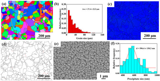
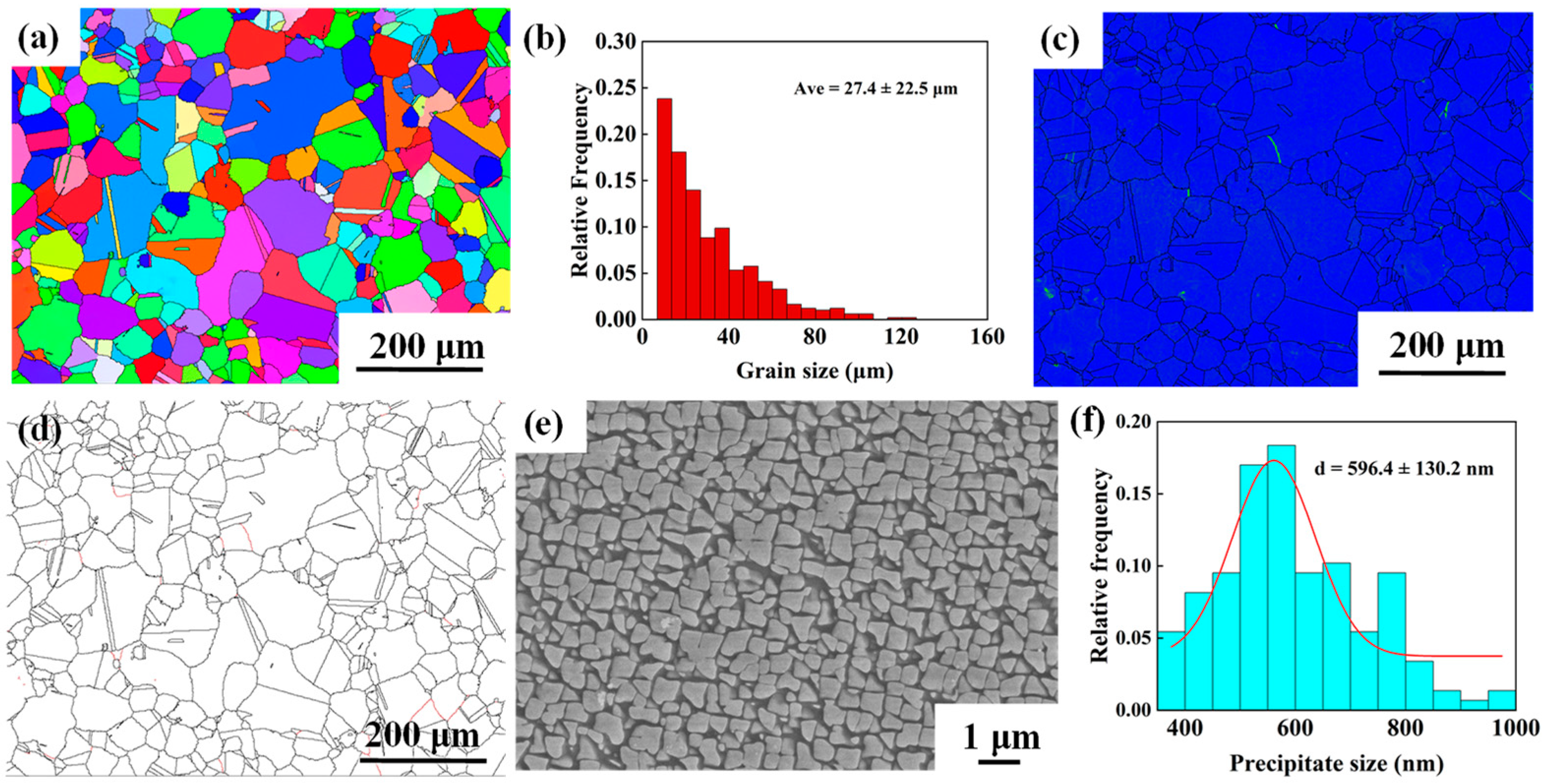
Figure 1 shows the initial microstructure of the FGH4097 alloy. The electron backscatter diffraction (EBSD) inverse pole figure (IPF) map in Figure 1a reveals a typical equiaxed-grain structure with randomly distributed orientations. The grain size distribution was non-Gaussian, with coarse and fine grains coexisting (note that γ′ was not distinguished during indexing). As shown in Figure 1b, the mean grain size was 27.4 μm. Figure 1c,d present the kernel average misorientation (KAM) map and grain boundary map, respectively. Most of the initial alloy exhibited low KAM values, with higher local misorientation restricted to a few grain boundaries and intragranular regions; the mean KAM value was 0.13°. High-angle grain boundaries (HAGBs) predominated, whereas low-angle grain boundaries (LAGBs) were sparsely distributed and represented only 2% of the boundaries. These results indicate limited local intragranular misorientation and few deformation substructures in the initial material. The precipitates shown in Figure 1e were mainly cuboidal, with some butterfly-shaped particles. The mean γ′ precipitate size determined from Figure 1f was 596.4 nm (from the equivalent circle diameter).
Figure 1.
Initial microstructural characterization of the FGH4097 superalloy: (a) IPF map; (b) grain size distribution; (c) KAM map; (d) grain boundary map showing LAGBs (red lines, 2–15°) and HAGBs (black lines, >15°); (e) scanning electron microscope image of precipitates; (f) precipitate size distribution.
2.2. Cold Expansion Procedure
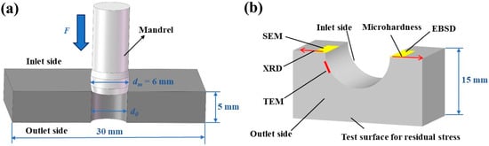
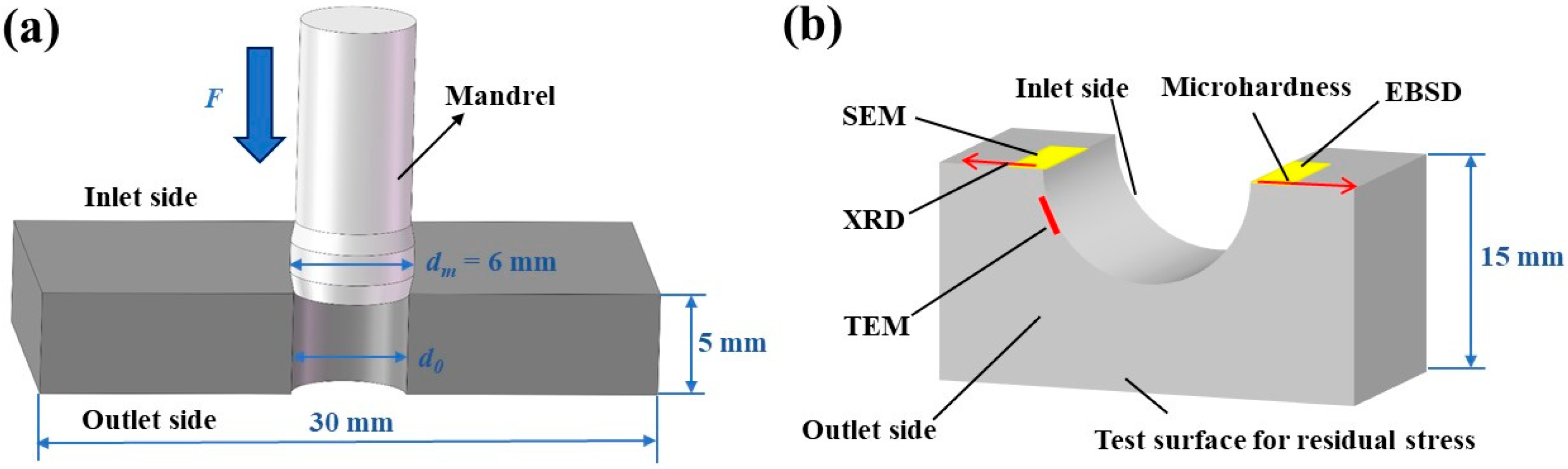
Square specimens measuring 30 mm × 30 mm × 5 mm were machined with a central through-hole. To obtain the specified interference levels, the nominal hole diameter (d0) was set to 5.64, 5.76, and 5.88 mm, respectively. Figure 2a shows the mandrel cold expansion process. A cylindrical mandrel with a 6 mm working-section diameter (dm) was driven axially to expand the hole in the specimen. The 6 mm working-section diameter was selected based on the fact that it is practically a common hole size.
Figure 2.
Schematic illustration of the cold expansion process and characterization locations: (a) mandrel cold expansion process; (b) sampling locations.
The interference I was defined as the difference between the mandrel working-section diameter dm and the hole diameter d0:
The relative expansion η was calculated as:
I = dm − d0
η = (dm − d0)/d0 × 100%
Interference (I), lead angle (A), lubrication condition (L), and mandrel speed (V) were selected as experimental factors. Each factor was assigned three levels, and nine tests were arranged using an L9(34) orthogonal array (Table 2). The interference values were 0.12, 0.24, and 0.36 mm. The lead-angle pairs were 3.0°/4.0°, 3.5°/4.5°, and 4.0°/5.0°, where the first and second values denote the inlet- and outlet-side angles, respectively. Lubrication conditions A, B, and C were prepared by mixing molybdenum disulfide powder (MoS2, purity ≥99%) with high-temperature grease at mass ratios of 1:5, 1:10, and 1:20, corresponding to MoS2 mass fractions of 16.7%, 9.1%, and 4.8%, respectively. The mandrel speeds were 15, 20, and 25 mm/min. The present study employed an L9(34) orthogonal array consisting of only nine experiments, which enables the assessment of main effects, while no degrees of freedom remain to quantify experimental error or resolve factor interactions.
Table 2.
L9(34) orthogonal experimental design for cold expansion.
2.3. Mechanical Testing and Microstructural Characterization
Microhardness before and after cold expansion was measured on a polished cross-section parallel to the hole axis using an HMV-G-FA Micro-Vickers Hardness Tester (Shimadzu Corporation, Kyoto, Japan) at the locations shown in Figure 2b. A load of 4.90 N (500 gf) was applied for 10 s. Residual stresses were measured by the hole-drilling method in accordance with ASTM E837-25 [22]. Measurements were made 0.5, 1.0, 1.5, and 2.0 mm from the hole wall on the surface shown in Figure 2b using an SCG520 gradient residual-stress measurement system (Shandong Huawin Electrical & Mechanical Technology Co., Ltd., Jinan, China). A 2 mm-diameter hole was drilled incrementally to a total depth of 1 mm using 0.05 mm depth increments for measurements.
EBSD was performed using a ZEISS GeminiSEM 300 field-emission scanning electron microscope (Carl Zeiss Microscopy GmbH, Jena, Germany) equipped with an Oxford Instruments AZtec EBSD system (AZtecCrystal 2.1). Grain morphology, orientation distribution, KAM, and grain boundary characteristics were evaluated. Specimens were ground sequentially with 400–2500 grit SiC papers, mechanically polished using a 2.5 μm diamond suspension, and then electropolished in perchloric acid–absolute ethanol (1:9 by volume).
X-ray diffraction (XRD) was conducted using a Malvern Panalytical X’Pert3 Powder diffractometer (Malvern Panalytical B.V., Almelo, The Netherlands) with Cu Kα radiation. Changes in diffraction-peak full width at half maximum (FWHM) were analyzed using the Williamson–Hall method to calculate microstrain and dislocation density, thereby quantifying lattice distortion and dislocation accumulation induced by cold expansion [23].
The deformation microstructure after cold expansion was examined using an FEI Talos F200X transmission electron microscope (TEM) (Thermo Fisher Scientific, Waltham, MA, USA) operated at 200 kV. The specimens were wire-cut perpendicular to the radial direction, mechanically thinned to approximately 60 μm, and punched into 3 mm-diameter disks. Electron-transparent foils were prepared by twin-jet electropolishing at 20 V in a perchloric acid–absolute ethanol solution (1:9 by volume). It should be noted that for EBSD, XRD, and TEM, radial positions were measured outward from the hole wall along the cross-section shown in Figure 2b; the nominal 0 mm position denotes the region immediately adjacent to the hole wall rather than a mathematical point.
3. Results
3.1. Effects of Processing Parameters on Microhardness
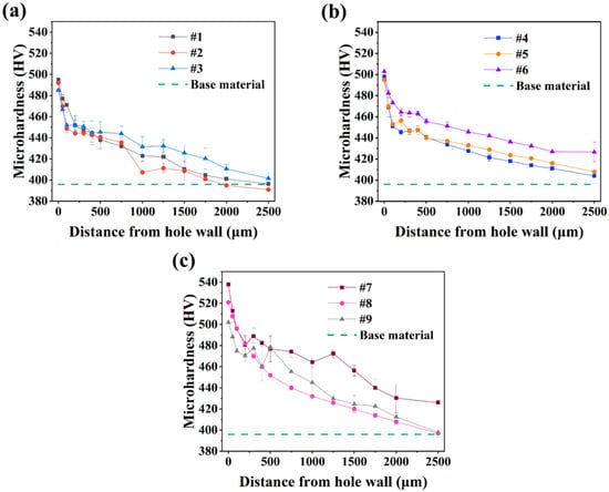
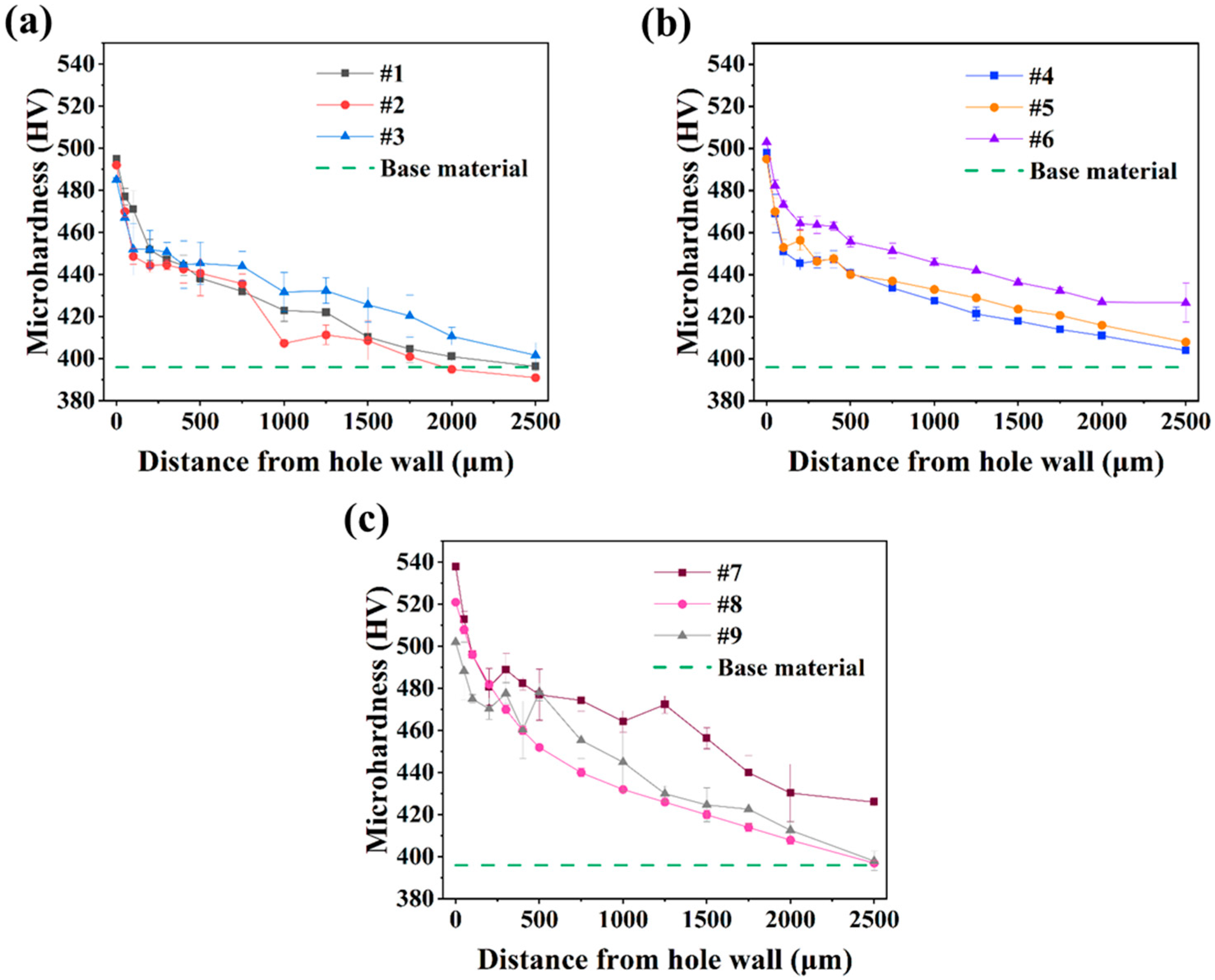
Figure 3 presents radial microhardness profiles for all nine cold-expanded specimens; Figure 3a–c correspond to samples 1–3, 4–6, and 7–9, respectively, with each three having the same interference level. Every specimen exhibited significant near-hole hardening and a pronounced microhardness gradient; the microhardness decreased with increasing distance from the hole wall and gradually approached the base-material value of 396 HV. The hardening effect was therefore concentrated near the hole wall and weakened with increasing radial distance. At the measurement point closest to the hole wall, the microhardness values of samples 1–9 were 495, 492, 485, 498, 495, 503, 538, 521, and 502 HV, respectively. Among them, sample 7 exhibited the highest microhardness of 538 HV, 36% higher than the base material, and retained a microhardness of 424 HV (7% increase) at 2500 μm from the hole wall, indicating a relatively broad hardening zone. By contrast, the microhardness of some specimens decreased markedly and approached the base-material level at shorter distances of 1000–2000 μm. Thus, the processing parameter combinations clearly influenced both the maximum microhardness and hardening depth.
Figure 3.
Radial microhardness distributions from the hole wall in cold-expanded FGH4097 specimens with different interference levels: (a) samples 1–3 with an interference of 0.24 mm; (b) samples 4–6 with an interference of 0.12 mm; (c) samples 7–9 with an interference of 0.36 mm.
Range analysis was performed using, for each specimen, the microhardness value measured at the location closest to the hole wall. The mean response at each factor level (k) and the corresponding range (R) are presented in Table 3. The R values for interference, lead angle, lubrication condition, and mandrel speed were 29.7, 13.7, 13.7, and 9.0 HV, respectively. A larger R value indicates a greater influence of the corresponding factor on the response. Thus, interference had the greatest effect on microhardness, the effects of lead angle and lubrication condition were comparable, and the mandrel speed had the weakest effect, giving the ranking I > A = L > V.
Table 3.
Range analysis of processing-parameter effects on the maximum microhardness.
3.2. Effects of Processing Parameters on Residual Stress
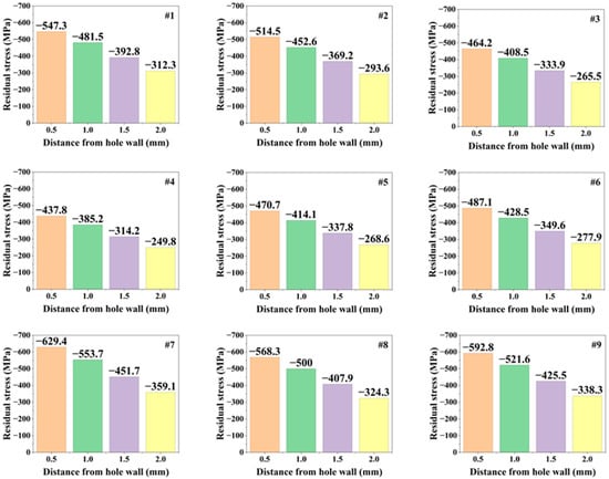
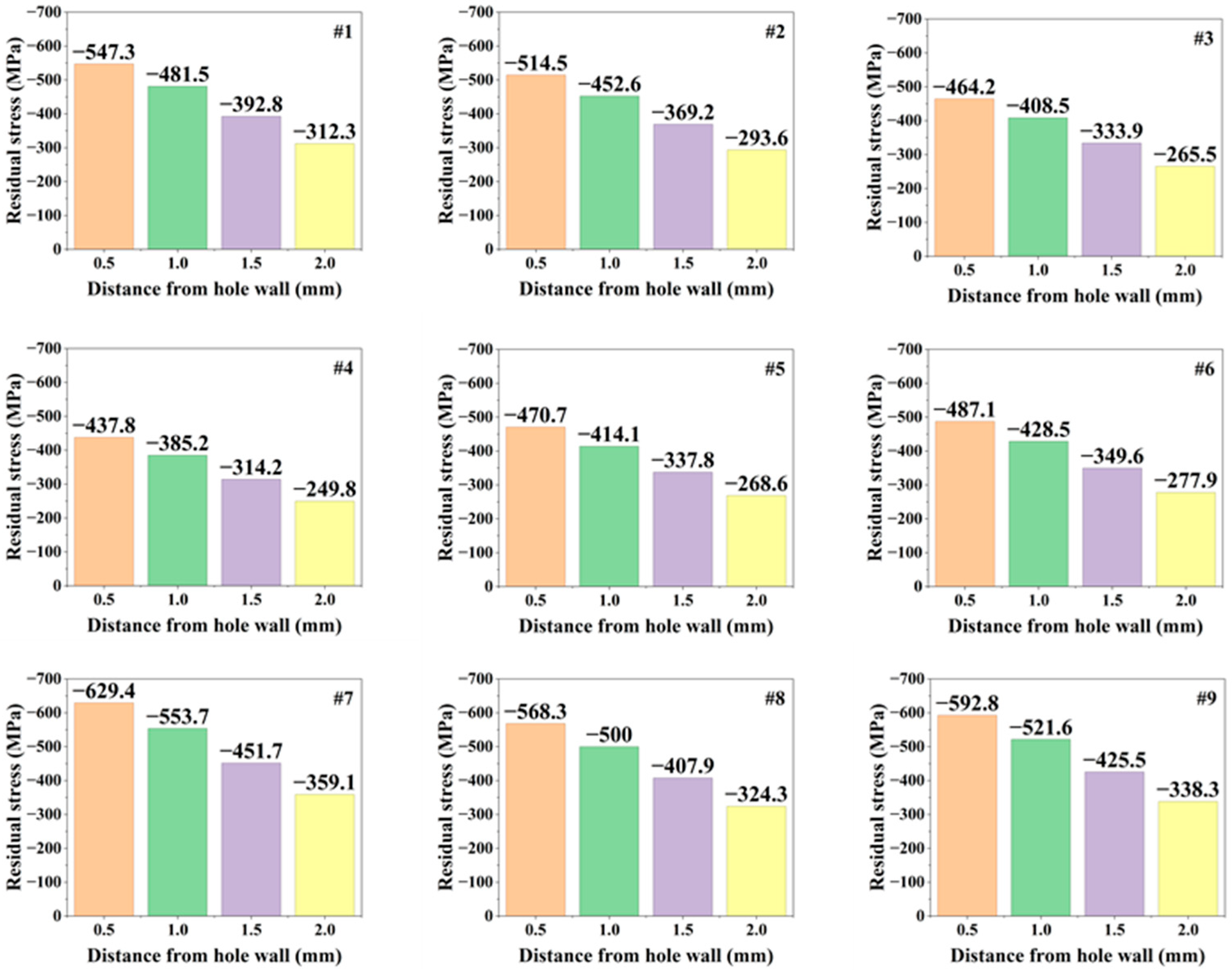
Figure 4 shows the residual-stress distributions at different radial positions for all specimens. The residual stress was negative at every measurement position, demonstrating that cold expansion generated compressive residual stresses near the hole wall. The compressive residual stress decreased with increasing radial distance from the hole wall, producing a clear gradient. At 0.5 mm from the hole wall, the residual stresses in samples 1–9 were −547.3, −514.5, −464.2, −437.8, −470.7, −487.1, −629.4, −568.3, and −592.8 MPa, respectively. Again, sample 7 showed the largest compressive residual stress of −629.4 MPa. The processing-parameter combinations therefore markedly affected the compressive residual stress.
Figure 4.
Residual-stress distributions at different distances from the hole wall for samples 1–9.
To compare the effects of processing parameters, the compressive residual stress at 0.5 mm from the hole wall was used for range analysis (Table 4). The R values for interference, lead angle, lubrication condition, and mandrel speed were 131.6, 23.5, 53.6, and 19.2 MPa, respectively, giving the ranking I >> L > A > V. Interference was again the dominant factor, followed by the lubrication condition, lead angle and mandrel speed.
Table 4.
Range analysis of processing-parameter effects on the compressive residual stress magnitude at 0.5 mm from the hole wall.
These results demonstrate that cold expansion produced both a gradient-hardened layer and a compressive residual stress field near the hole wall in FGH4097 superalloy. The processing parameters markedly affected both the near-hole microhardness and the compressive residual stress, with interference exerting the strongest influence on both responses. Among the nine tested combinations, sample 7, which used an interference of 0.36 mm, lead angles of 3.5°/4.5°, lubrication condition B, and a mandrel speed of 25 mm/min, exhibited the highest microhardness of 538 HV and the largest compressive residual stress of −629.4 MPa at 0.5 mm from the hole wall.
3.3. Microstructural Characteristics
As sample 7 is regarded as the best-performing condition among the tested combinations, subsequent EBSD, XRD, and TEM characterization was therefore focused on it.
3.3.1. EBSD Characterization
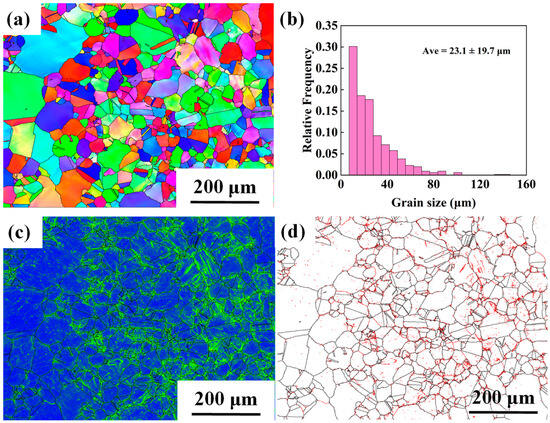
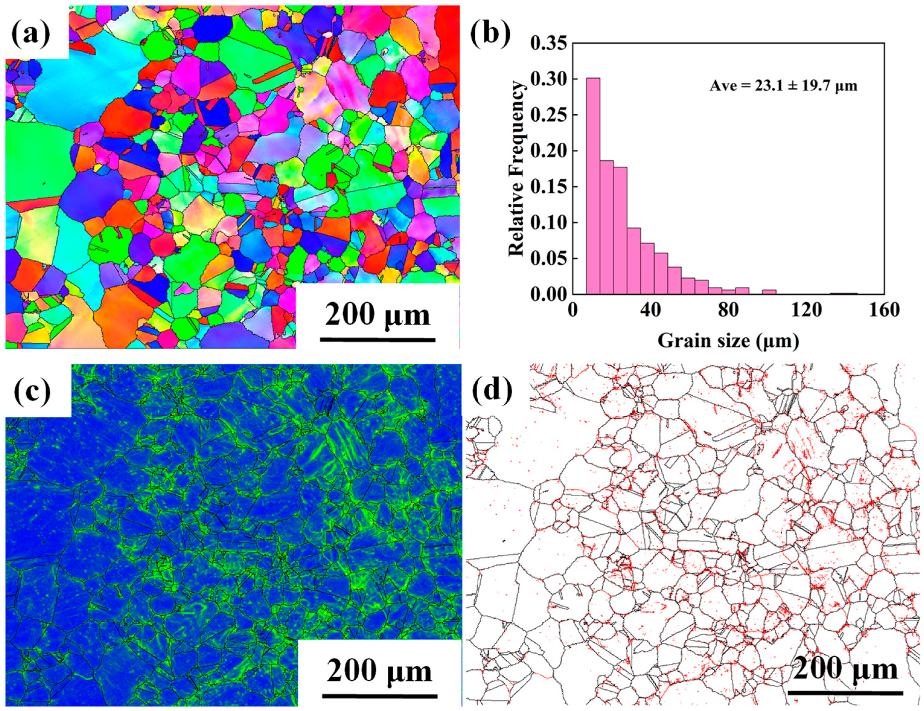
Figure 5 presents the EBSD results for sample 7 at the nominal 0 mm position. The specimen clearly retained the equiaxed-grain morphology after cold expansion, with randomly distributed orientations and no obvious preferred texture (Figure 5a). The mean grain size was 23.1 μm (Figure 5b), indicating no pronounced change in grain size either. In contrast, the KAM map in Figure 5c shows higher values near some grain boundaries and in local intragranular regions. The mean KAM value was 0.69°, demonstrating a substantial local misorientation increase after cold expansion. In Figure 5d, red lines denote LAGBs, which also increased compared to Figure 1. These boundaries were concentrated within grains and near some grain boundaries and accounted for 36% of the total boundaries.
Figure 5.
EBSD characterization of sample 7 at the nominal 0 mm position: (a) IPF orientation map; (b) grain size distribution; (c) KAM map; (d) grain boundary distribution map.
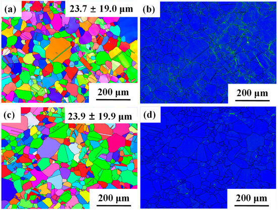
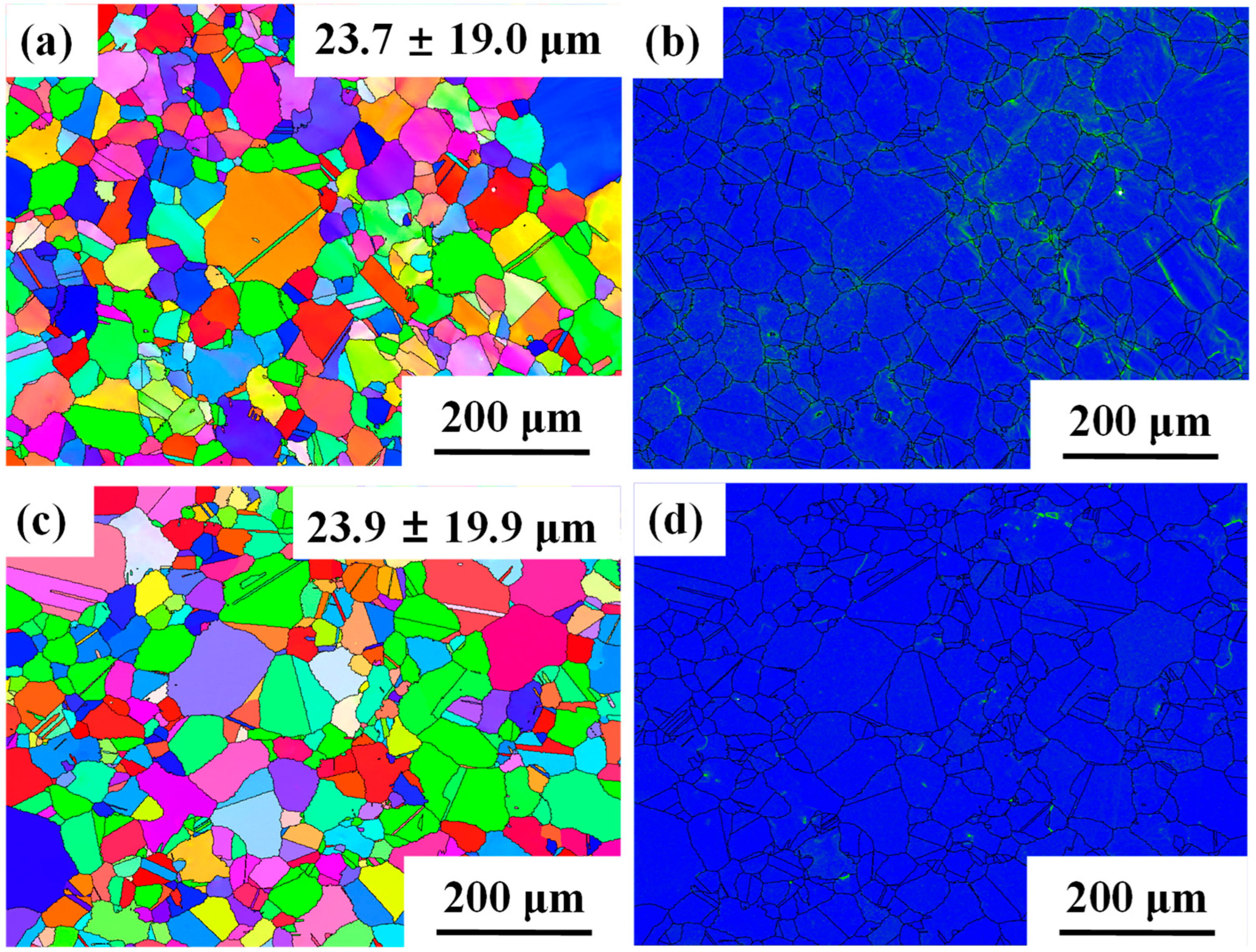
Figure 6 presents the EBSD results of sample 7 at 1 mm and 5 mm from the hole wall. At 1 mm, the grains remained equiaxed with a random orientation distribution, and the mean grain size was 23.7 μm (Figure 6a). The KAM map showed low values, with relatively high KAM values localized near grain boundaries and in some intragranular regions (Figure 6b). The mean KAM value was 0.30°, substantially lower than the nominal 0 mm value of 0.69°, indicating a marked reduction in local intragranular misorientation with increasing radial distance from the hole wall. At 5 mm, the grains remained equiaxed and randomly oriented, with a mean grain size of 23.9 μm (Figure 6c). The KAM values were further reduced, and the mean KAM value decreased to 0.14° (Figure 6d), approaching that of the initial alloy. Overall, the grain morphology and orientation distribution remained essentially unchanged, whereas the local intragranular misorientation progressively decreased from 1 to 5 mm, indicating that the deformation introduced by cold expansion was largely confined to the region near the hole wall.
Figure 6.
EBSD characterization of sample 7 at 1 mm and 5 mm from the hole wall: (a) IPF orientation map at 1 mm; (b) KAM map at 1 mm; (c) IPF orientation map at 5 mm; (d) KAM map at 5 mm.
3.3.2. XRD Analysis
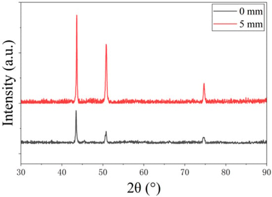
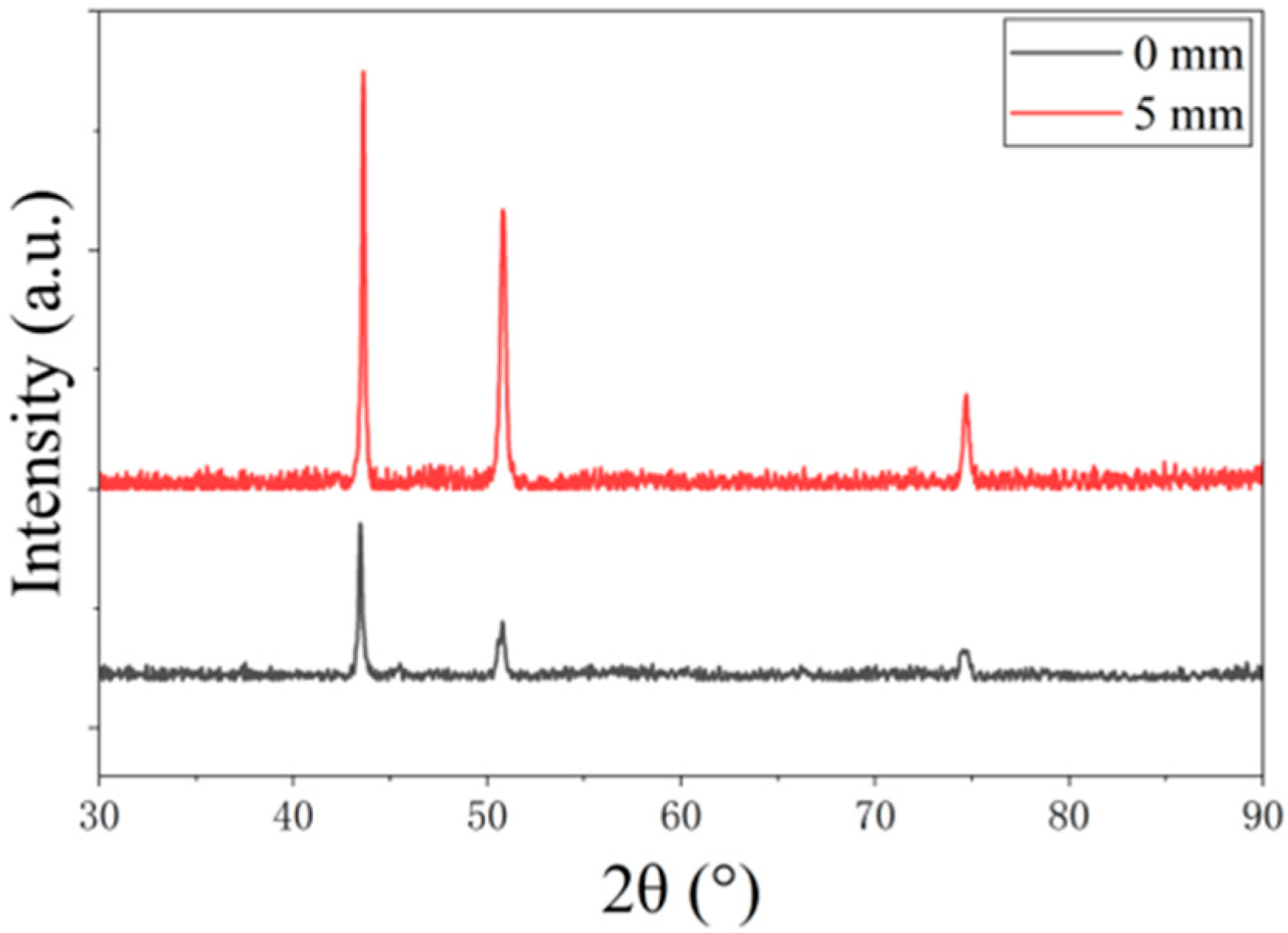
Figure 7 compares the XRD patterns of sample 7 at the nominal 0 mm and 5 mm positions. Because the region at 5 mm was only weakly affected by cold-expansion-induced plastic deformation, it was treated as an approximately undeformed base-material reference. Comparing the diffraction peaks from these regions therefore reveals cold-expansion-induced lattice distortion, microstrain, and dislocation accumulation.
Figure 7.
XRD patterns of sample 7 at the nominal 0 mm and 5 mm positions.
Both positions exhibited the same principal diffraction peaks, indexed to the (111), (200), and (220) planes, and no other clearly resolved phase peaks were observed. The FWHM values at the nominal 0 mm position were consistently higher than those at 5 mm. The (111) FWHM increased from 0.22° at 5 mm to 0.26° at the nominal 0 mm position; the corresponding increases for the (200) and (220) peaks were from 0.32° to 0.39° and from 0.36° to 0.44°, respectively. The consistent broadening of all three peaks at the nominal 0 mm position indicates greater microstrain and defect accumulation near the hole wall. The higher FWHM values at the nominal 0 mm position are attributed primarily to the stronger plastic deformation introduced during mandrel passage. The material adjacent to the hole experiences the largest plastic strain and therefore develops greater lattice distortion, microstrain, and dislocation accumulation. These defects increase the distribution of lattice spacings and diffraction angles, resulting in broader diffraction peaks and higher FWHM values. In contrast, the region at 5 mm from the hole experiences weaker plastic deformation and therefore exhibits lower microstrain and dislocation density. It should be noted that the increased FWHM primarily reflects microstructural defect accumulation and microstrain, rather than directly representing macroscopic residual stress.
The Williamson–Hall method was used to quantify peak broadening and calculate microstrain and dislocation density. Peak broadening was treated as the combined effect of crystallite size and microstrain, expressed as
where β is the FWHM of the characteristic diffraction peak associated with the γ/γ′ phases, θ is the Bragg angle, D is the crystallite size (μm), λ is the Cu Kα wavelength (1.54 Å), and ε is the microstrain. The dislocation density was then calculated from the microstrain as
where b is the Burgers vector, taken as 0.254 nm for nickel-based alloys [24]. As shown in Table 5, the microstrain at the nominal 0 mm position was 0.157%, higher than the value of 0.124% at 5 mm. The corresponding dislocation densities were 1.53 × 10¹⁴ and 9.53 × 10¹³ m−2, respectively.
β cos θ/λ = 1/D + 4ε sin θ/λ
ρ = 4ε2/b2
Table 5.
Williamson–Hall analysis of sample 7 at the nominal 0 mm and 5 mm positions.
3.3.3. TEM Characterization
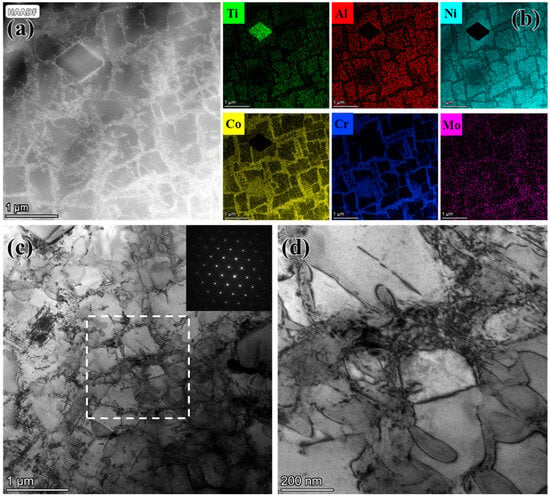
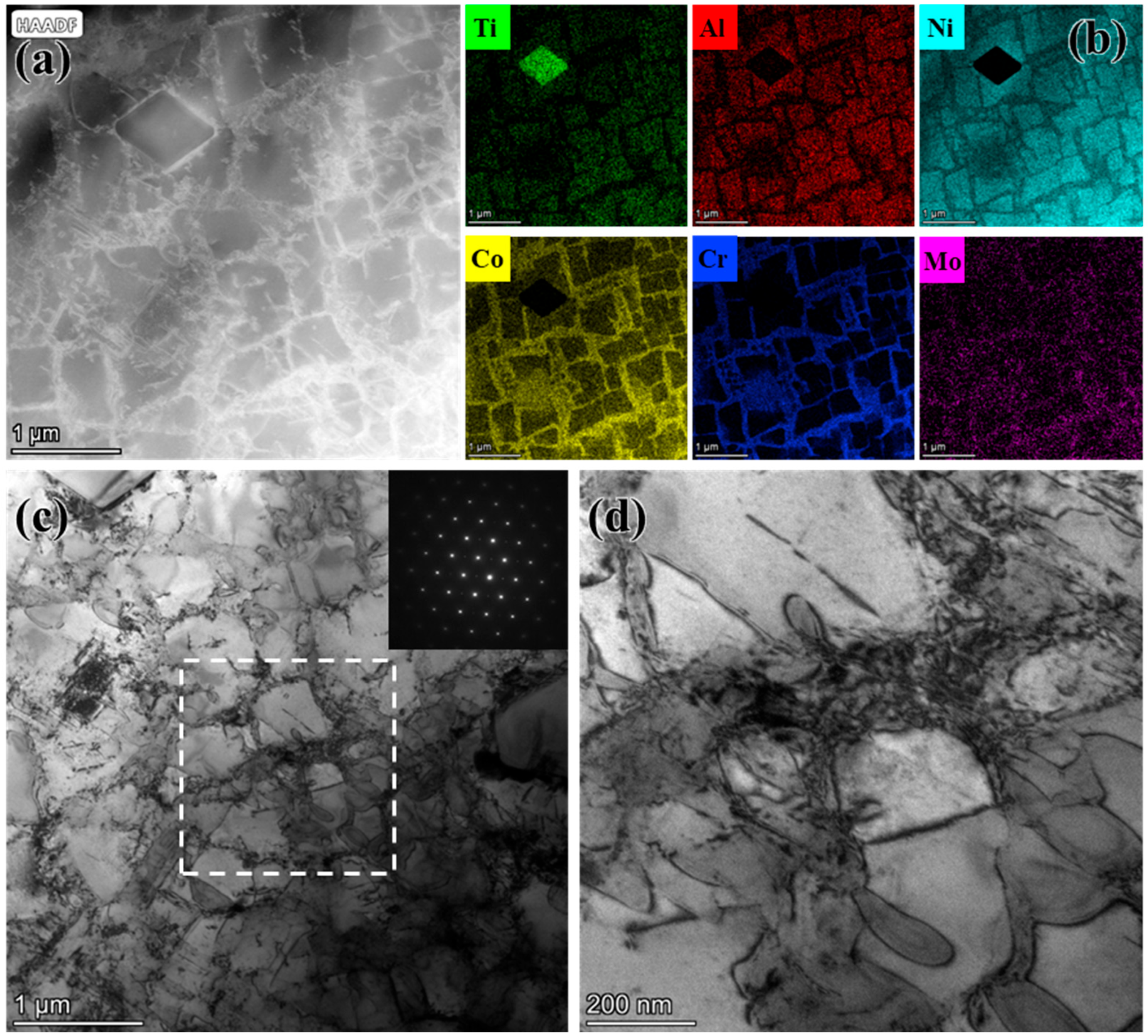
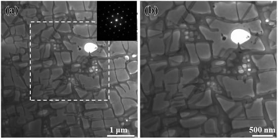
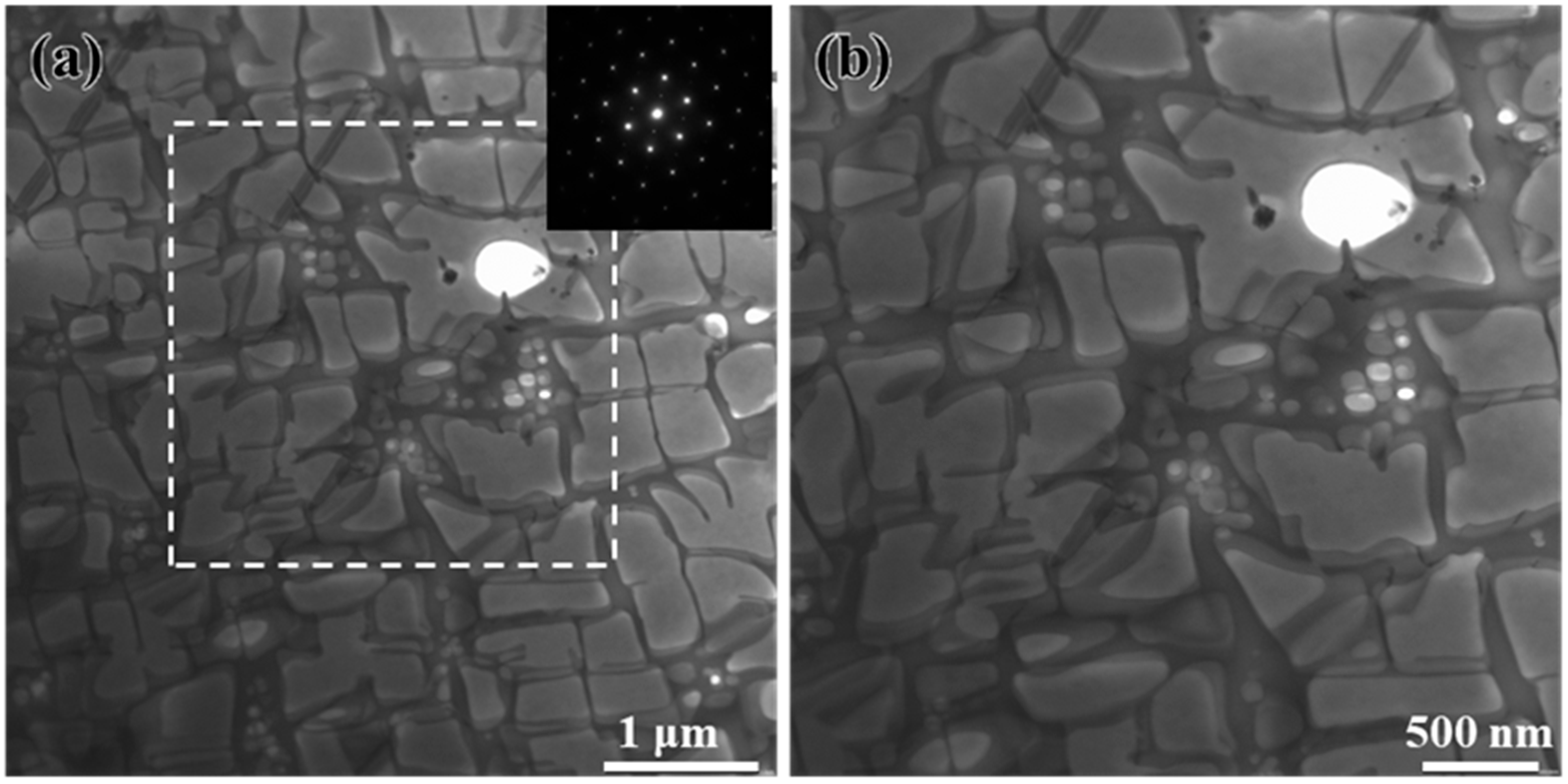
Figure 8 presents the deformation microstructure of sample 7 at the nominal 0 mm position characterized by STEM. Figure 8a shows a high-angle annular dark-field STEM (HAADF-STEM) image, and Figure 8b presents the corresponding EDS elemental maps. Large cuboidal second-phase γ′ particles were present in the matrix. The low-magnification bright-field STEM image in Figure 8c includes a selected-area electron diffraction (SAED) pattern acquired along the [110] zone axis. Numerous dislocations and pronounced local dislocation accumulations were observed at the nominal 0 mm position, showing that it underwent substantial plastic deformation. The higher-magnification image in Figure 8d, acquired from the dashed area in Figure 8c, reveals dislocation tangling and pronounced dislocation piling-ups at γ/γ′ interfaces. The dislocations were concentrated primarily in the γ matrix, with pronounced accumulation at γ/γ′ interfaces.
Figure 8.
STEM characterization of the deformation microstructure of sample 7 at the nominal 0 mm position: (a) HAADF-STEM image; (b) corresponding EDS elemental maps; (c) low-magnification BF-STEM image and corresponding SAED pattern; (d) high-magnification BF-STEM image of the dashed region in (c).
Figure 9 shows the deformation microstructure of sample 7 at 5 mm from the hole wall, observed along the [110] zone axis. In contrast to the microstructure at the nominal 0 mm position, which contained numerous dislocations, dislocation tangling, and pronounced dislocation piling-ups at γ/γ′ interfaces, the microstructure at the 5 mm position exhibited much weaker dislocation contrast, indicating a substantially lower degree of plastic deformation.
Figure 9.
STEM characterization of sample 7 at 5 mm from the hole wall: (a) low-magnification STEM image and corresponding SAED pattern acquired along the [110] zone axis; (b) enlarged image of the dashed region in (a).
4. Discussion
For sample 7, microhardness was highest near the hole wall and gradually decreased toward the base-material level with increasing radial distance. This gradient confirms that cold-expansion-induced strengthening was concentrated near the hole. The mean grain size changed only from 27.4 ± 22.5 μm before expansion to 23.1 ± 19.7 μm near the wall after expansion, with no clear evidence of grain refinement. Grain refinement was therefore not the primary strengthening mechanism.
EBSD revealed pronounced intragranular structural evolution. The mean KAM value was 0.69° at the nominal 0 mm position, compared with 0.30° at 1 mm and 0.14° at 5 mm, demonstrating that local misorientation and deformation-substructure development were concentrated near the hole wall.
Williamson–Hall analysis provided quantitative support for dislocation accumulation. The microstrain was 0.157% at the nominal 0 mm position and 0.124% at 5 mm, with corresponding dislocation densities of 1.53 × 10¹⁴ and 9.53 × 10¹³ m−2. The nominal 0 mm value was approximately 1.6 times the 5 mm reference value.
TEM observations were consistent with the EBSD and XRD results. Numerous dislocations, dislocation tangling, and piling-ups were present near the hole wall, whereas the dislocation contrast and accumulation were markedly reduced at 5 mm. According to the Taylor dislocation-strengthening relationship, the stress increment caused by dislocations can be expressed as [25]
where α is the dislocation-interaction coefficient, M is the Taylor factor, G is the shear modulus, b is the Burgers vector, and ρ is the dislocation density. Using the approximate proportionality between microhardness and stress, the microhardness increment due to dislocation strengthening can be written as [26]
where k is a material-dependent constant and ΔHv is the microhardness increment. Equations (5) and (6) imply an approximately linear relationship between the microhardness increment and the square root of dislocation density. Under the proportionality in Equation (6), the 1.6-fold increase in dislocation density corresponds to an estimated 27% increase in the dislocation-strengthening contribution to microhardness. Within the present experimental range, dislocation multiplication, dislocation–dislocation interactions, and interactions between dislocations and γ′ precipitates are therefore the principal microstructural causes of near-hole work hardening and microhardness elevation.
ΔHv = kΔσdis
Range analysis showed that interference had the largest effect on the microhardness measured at the location closest to the hole wall, with R = 29.7 HV. The mean microhardness values at interference levels of 0.12, 0.24, and 0.36 mm were 498.7, 490.7, and 520.3 HV, respectively. Finite-element studies have shown that increasing expansion within a suitable range increases plastic strain near the hole wall [27]. More intense plastic deformation promotes dislocation multiplication, interaction, and local storage, thereby increasing resistance to dislocation motion. The high microhardness obtained at 0.36 mm interference can thus be attributed mainly to stronger plastic deformation and the resulting dislocation accumulation, supporting interference as the dominant factor. However, increasing interference from 0.12 to 0.24 mm slightly decreased, rather than increased, the mean microhardness. The relationship is therefore not simply linear. At relatively low interference, the incremental plastic strain may be insufficient to produce a clearly resolvable microhardness difference, while lead angle, lubrication condition, mandrel speed, and possible factor interactions also contribute to the measured microhardness.
Macroscopic compressive residual stress generated by cold expansion is generally attributed to heterogeneous deformation between the plastically expanded near-hole region and the surrounding elastic region, together with their mismatched elastic–plastic recovery during unloading. During mandrel passage, material adjacent to the hole wall undergoes irreversible plastic expansion, while remote material remains elastic. During unloading, incompatible recovery between the plastically expanded near-hole region and the surrounding elastic material generates a self-equilibrated residual-stress field, leaving compressive residual stress near the hole wall [9,17].
All cold-expanded specimens exhibited compressive residual stress near the hole wall and decreased with increasing radial distance. This trend paralleled the changes in microhardness and KAM, confirming that the microstructural and mechanical effects were strongest near the hole wall and decayed toward the remote region. Interference had the largest effect on the compressive residual stress, with R = 131.6 MPa. At interference levels of 0.12, 0.24, and 0.36 mm, the mean compressive residual stress was −465.2 MPa, −508.7 MPa, and −596.8 MPa, respectively. This trend agrees with Liu et al. [18], who found that the peak compressive residual stress increased with expansion level. Greater interference increases the radial expansion and produces greater plastic strain near the hole wall [27]. Because the residual-stress field arises from incompatible recovery between the surrounding elastic material and the permanently expanded near-hole region [28], the larger plastic strain at higher interference plausibly increases this mismatch and thus the compressive residual stress. The gradient-hardened layer and compressive residual stress field observed here are expected to improve fatigue performance by delaying fatigue-crack initiation and propagation [3,4]. However, verification of this benefit requires direct fatigue testing, which was beyond the scope of the present study.
Several aspects require further investigation. First, more experiments need to be performed to conduct F and p-value analysis and examine interactions between the different factors. Second, single-factor experiments will be adopted to elaborate the influence of individual variables. Third, direct mandrel hole expansion may induce asymmetric deformation on both sides of specimens; hence, the microhardness and residual stress distributions on both sides need to be further investigated. In addition, fatigue tests are required to explore the effect of the hole cold-expansion process on the fatigue performance of specimens.
5. Conclusions
An L9(34) orthogonal experiment was performed to evaluate the effects of cold expansion parameters. Based on the mechanical testing and microstructural characterization results, the following conclusions can be drawn.
- (1)
- Cold expansion produced a pronounced gradient-hardened layer and a compressive residual stress field near the hole wall in FGH4097 superalloy. Among the nine tested combinations, the highest microhardness of 538 HV and the largest compressive residual stress of −629.4 MPa at 0.5 mm from the hole wall were obtained (condition 7). Both the microhardness and compressive residual stress decreased with increasing radial distance. Orthogonal testing and range analysis identified interference as the dominant processing parameter for both responses; the importance of processing parameters was identified as I > A = L > V for microhardness and I >> L > A > V for residual stress.
- (2)
- Cold-expansion-induced plastic deformation was concentrated near the hole wall. The initial equiaxed grain structure was retained, and grain size remained basically unchanged, whereas local misorientation, microstrain, and dislocation density increased significantly. The mean KAM value and dislocation density at the nominal 0 mm position were significantly higher than those in the remote region. TEM further revealed dense dislocation tangling and piling-ups at γ/γ′ interfaces near the hole wall.
- (3)
- The increased near-hole microhardness arose from cold-expansion-induced dislocation multiplication, dislocation–dislocation interactions, and the impediment of dislocation motion by γ′ precipitates. Within the investigated range, the compressive residual stress increased with interference, plausibly because greater near-hole plastic deformation increased the mismatch between the plastically deformed zone and the surrounding material.
Author Contributions
Conceptualization, B.Z., L.Z., H.C. and G.W.; methodology, B.Z., S.L., Y.W. and W.Z.; validation, B.Z., W.Z., S.L. and Y.W.; formal analysis, W.Z., S.L. and Y.W.; investigation, B.Z., W.Z., S.L. and Y.W.; resources, L.Z., H.C., J.L. and G.W.; data curation, W.Z., S.L. and Y.W.; writing and original draft preparation, W.Z. and Y.W.; writing—review and editing, L.Z., H.C., J.L. and G.W.; visualization, B.Z., W.Z., S.L. and Y.W.; supervision, L.Z., H.C., J.L. and G.W.; project administration, B.Z., J.L. and G.W.; funding acquisition, L.Z. and J.L. All authors have read and agreed to the published version of the manuscript.
Funding
This work was supported by the National Natural Science Foundation of China (Project No. T2421001), the State Key Laboratory of Mechanical Transmissions for Advanced Equipment (Project No. SKLMT-ZZKT-2025Z07), the Natural Science Foundation of Chongqing (Project No. CSTB2023NSCQ-LZX0102), and the National Natural Science Foundation of China (Project No. U23A6016).
Data Availability Statement
The original contributions presented in this study are included in the article. Further inquiries can be directed to the corresponding authors.
Conflicts of Interest
The authors declare no conflicts of interest.
References
- Yu, C.; Wang, Q.; Chen, M.; Wang, F. Microstructures and Oxidation Behavior of PM Ni-Based Superalloy FGH97 with in-Situ Carbide Precipitates. Corros. Sci. 2023, 220, 111295. [Google Scholar] [CrossRef] [Scilit]
- Liu, J.; Xu, H.; Zhai, H.; Yue, Z. Effect of Detail Design on Fatigue Performance of Fastener Hole. Mater. Des. 2010, 31, 976–980. [Google Scholar] [CrossRef] [Scilit]
- Wang, Y.; Zhu, Y.; Hou, S.; Sun, H.; Zhou, Y. Investigation on Fatigue Performance of Cold Expansion Holes of 6061-T6 Aluminum Alloy. Int. J. Fatigue 2017, 95, 216–228. [Google Scholar] [CrossRef] [Scilit]
- Yao, S.; Lei, X.; Wang, R.; He, C.; Zhang, X.; Tu, S. A Novel Cold Expansion Process for Improving the Surface Integrity and Fatigue Life of Small-Deep Holes in Inconel 718 superalloys. Int. J. Fatigue 2022, 154, 106544. [Google Scholar] [CrossRef] [Scilit]
- Yang, K.; Chen, X.; Lv, X.; Ding, F.; Dang, B.; Li, F.; Wei, D.; Zhang, P. Effect of Split-Sleeve Cold Hole Expansion on the Fatigue Performance of an Additive Manufactured TC18 alloy. J. Mater. Res. 2023, 38, 841–852. [Google Scholar] [CrossRef] [Scilit]
- Wang, J.; Lei, X.; Zeng, F.; Li, W.; He, C.; Cheng, L.; Zhang, X. Design of a Novel Cold Expansion Tool for Deep Small Holes Based on FEM Simulations and Experimental Study. Int. J. Adv. Manuf. Technol. 2024, 130, 4933–4949. [Google Scholar] [CrossRef] [Scilit]
- Che, H.; Zhang, Z.; Wang, Y.; Li, S.; Zhang, L. Surface Strengthening of IF Steel by High-Velocity Cold Spray Shot Peening. J. Therm. Spray. Technol. 2026, 35, 2054–2065. [Google Scholar] [CrossRef] [Scilit]
- Fu, Y.; Ge, E.; Su, H.; Xu, J.; Li, R. Cold Expansion Technology of Connection Holes in Aircraft Structures: A Review and Prospect. Chin. J. Aeronaut. 2015, 28, 961–973. [Google Scholar] [CrossRef] [Scilit]
- Gopalakrishna, H.D.; Narasimha Murthy, H.N.; Krishna, M.; Vinod, M.S.; Suresh, A.V. Cold Expansion of Holes and Resulting Fatigue Life Enhancement and Residual Stresses in Al 2024 T3 alloy–An Experimental Study. Eng. Fail. Anal. 2010, 17, 361–368. [Google Scholar] [CrossRef] [Scilit]
- Su, R.; Li, J.; Liu, W.; Xu, C.; Gao, L.; Liang, X.; Wu, D.; Huang, X.; Dong, H.; Ma, H. Investigation on Fatigue Failure of Split-Sleeve Cold Expansion Holes of 7075-T651 Aluminum Alloy. Mater. Today Commun. 2023, 35, 106290. [Google Scholar] [CrossRef] [Scilit]
- Curto-Cárdenas, D.; Calaf-Chica, J.; Bravo Díez, P.M.; Preciado Calzada, M.; Garcia-Tarrago, M.J. Cold Expansion Process with Multiple Balls—Numerical Simulation and Comparison with Single Ball and Tapered Mandrels. Materials 2020, 13, 5536. [Google Scholar] [CrossRef] [Scilit] [PubMed]
- Chakherlou, T.N.; Vogwell, J. The Effect of Cold Expansion on Improving the Fatigue Life of Fastener Holes. Eng. Fail. Anal. 2003, 10, 13–24. [Google Scholar] [CrossRef] [Scilit]
- Kokaly, M.T.; Ransom, J.S.; Restis, J.H.; Reid, L. Predicting Fatigue Crack Growth in the Residual Stress Field of a Cold Worked Hole. J. ASTM Int. 2005, 2, 1–13. [Google Scholar] [CrossRef] [Scilit]
- Amrouche, A.; Mesmacque, G.; Garcia, S.; Talha, A. Cold Expansion Effect on the Initiation and the Propagation of the Fatigue Crack. Int. J. Fatigue 2003, 25, 949–954. [Google Scholar] [CrossRef] [Scilit]
- Webster, G.A.; Ezeilo, A.N. Residual Stress Distributions and Their Influence on Fatigue Lifetimes. Int. J. Fatigue 2001, 23, 375–383. [Google Scholar] [CrossRef] [Scilit]
- Wan, N.; Zhao, B.; Ding, W.; He, Q. Research Status and Tendency on Cold Expansion Anti-Fatigue Manufacturing Technology for Aircraft Structural Fastening Holes. J. Manuf. Process. 2025, 141, 319–335. [Google Scholar] [CrossRef] [Scilit]
- Ribeiro, R.L.; Hill, M.R. Residual Stress from Cold Expansion of Fastener Holes: Measurement, Eigenstrain, and Process Finite Element Modeling. J. Eng. Mater. Technol. 2017, 139, 041012. [Google Scholar] [CrossRef] [Scilit]
- Liu, Y.; Shao, X.; Liu, J.; Yue, Z. Finite Element Method and Experimental Investigation on the Residual Stress Fields and Fatigue Performance of Cold Expansion Hole. Mater. Des. 2010, 31, 1208–1215. [Google Scholar] [CrossRef] [Scilit]
- Özdemir, A.T.; Hermann, R. Effect of Expansion Technique and Plate Thickness on Near-Hole Residual Stresses and Fatigue Life of Cold Expanded Holes. J. Mater. Sci. 1999, 34, 1243–1252. [Google Scholar] [CrossRef] [Scilit]
- Mostefa, B.; Aid, A.; Benhamena, A.; Mohamed, B. Effect of Hardening Induced by Cold Expansion on Damage Fatigue Accumulation and Life Assessment of Aluminum Alloy 6082 T6. Mater. Res. 2012, 15, 981–985. [Google Scholar] [CrossRef] [Scilit]
- Dey, M.K.; Kim, D.; Tan, H. Finite Element Parametric Study of the Split Sleeve Cold Expansion on Residual Stresses and Pulling Force. Proc. Inst. Mech. Eng. Part C J. Mech. Eng. Sci. 2022, 236, 2447–2461. [Google Scholar] [CrossRef] [Scilit]
- ASTM E837-25; Standard Test Method for Determining Residual Stresses by the Hole-Drilling Strain-Gage Method. ASTM International: West Conshohocken, PA, USA, 2025. [CrossRef] [Scilit]
- Williamson, G.K.; Hall, W.H. X-Ray Line Broadening from Filed Aluminium and Wolfram. Acta Metall. 1953, 1, 22–31. [Google Scholar] [CrossRef] [Scilit]
- Zhong, L.; Fan, X.; Wang, X.; Liu, Y.; Cui, J.; Hou, X.; Shi, Y.; Du, H.; Wei, Y.; Wang, J.; et al. Precisely Regulating the Size and Morphology of γ′ Strengthened a Novel Nickel-Based Superalloy via Varied Cooling Rates. J. Mater. Res. Technol. 2025, 36, 2403–2413. [Google Scholar] [CrossRef] [Scilit]
- Wang, Y.; Xu, G.; Gong, S.; Li, S.; Deng, J.; Wang, T.; Liu, Z.; Guo, W. Research on the Influence of Different Aging Temperatures on the Microstructure and Properties of GH2787 Alloy. Crystals 2026, 16, 81. [Google Scholar] [CrossRef] [Scilit]
- Zhang, P.; Li, S.; Zhang, Z. General Relationship Between Strength and Hardness. Mater. Sci. Eng. A 2011, 529, 62–73. [Google Scholar] [CrossRef] [Scilit]
- Hu, Q.; Zou, G.; Zhuang, Z.; Wang, J.; Xue, Q. An Integrated Experimental and Simulation Study on Residual Stress and Fatigue Life of TC4 Alloy Subjected to Cold Expansion and Reaming. Fatigue Fract. Eng. Mater. Struct. 2026, 49, 1680–1697. [Google Scholar] [CrossRef] [Scilit]
- Houghton, S.J.; Campbell, S.K. Identifying the Residual Stress Field Developed by Hole Cold Expansion Using Finite Element Analysis. Fatigue Fract. Eng. Mater. Struct. 2012, 35, 74–83. [Google Scholar] [CrossRef] [Scilit]

Disclaimer/Publisher’s Note: The statements, opinions and data contained in all publications are solely those of the individual author(s) and contributor(s) and not of MDPI and/or the editor(s). MDPI and/or the editor(s) disclaim responsibility for any injury to people or property resulting from any ideas, methods, instructions or products referred to in the content. |
© 2026 by the authors. Licensee MDPI, Basel, Switzerland. This article is an open access article distributed under the terms and conditions of the Creative Commons Attribution (CC BY) license.