


Abstract
Under-race lubrication is an effective oil supply method for high-speed angular contact ball bearings, but the relationship between internal oil–air two-phase flow distribution and end oil return behavior remains insufficiently understood. In this study, a Volume of Fluid (VOF)-based oil–air two-phase flow model was developed for an under-race lubricated angular contact ball bearing and validated experimentally. The effects of oil flow rate, rotational speed, inlet-hole axial position, diameter, and number were investigated. The maximum relative error between the numerical and experimental oil return ratios was 3.17%. At 3000 rpm, increasing the oil flow rate from 65 to 140 L/h increased the average oil volume fraction on the rolling element surfaces from approximately 0.037 to 0.089. In contrast, increasing rotational speed reduced oil retention on bearing component surfaces and the oil return ratio at the large-clearance end. At 140 L/h, the oil return ratio decreased from approximately 97% at 3000 rpm to 86.5% at 6000 rpm. Shifting the inlet holes toward the small-clearance end enhanced cage wetting but reduced oil retention on the rolling elements and large-clearance-end oil return. Within the investigated range, a mid-plane inlet position, smaller inlet-hole diameter, and larger number of inlet holes were more favorable for oil delivery to the rolling elements while maintaining a relatively high oil return ratio.
1. Introduction
Angular contact ball bearings are widely used in aero-engines, high-speed spindles, and precision transmission systems because of their high-speed capability and combined radial-axial load-carrying capacity. Under high-speed conditions, the lubrication state directly affects friction, temperature rise, wear, and service reliability. Grujičić et al. showed that shaft speed, external load, temperature, lubricant properties, and bearing geometry strongly influence the lubrication regime of ball bearings [1]. Sun et al. further demonstrated that oil film thickness increases with speed and decreases with load, indicating the sensitivity of bearing lubrication to operating conditions [2]. In high-speed bearing systems, thermal behavior is also closely related to oil supply. Jiang and Mao experimentally confirmed that oil supply parameters, preload, viscosity, nozzle structure, and speed affect bearing temperature rise [3]. Zheng et al. proposed a thermal model for angular contact ball bearings based on oil–air two-phase flow, emphasizing the importance of internal oil–air behavior in temperature prediction [4].
Lubricant inside a rolling bearing is not uniformly distributed, but migrates among raceways, rolling elements, cage surfaces, and local gaps. Gao et al. found that gravity and surface tension jointly control oil redistribution and replenishment on the inner raceway after shutdown [5]. Liang et al. showed that cage structure and surface wettability significantly affect oil migration and the oil supply near the ball-raceway contact region [6]. Chen et al. revealed that much of the oil attached to bearing components does not directly participate in contact lubrication, which means that the supplied oil amount cannot fully represent the effective lubrication state [7]. Tohyama et al. visualized high-speed oil-lubricated ball bearings and observed reduced inlet oil supply and enlarged oil-depleted regions at high rotational speeds [8].
Computational fluid dynamics (CFD), especially the Volume of Fluid (VOF) method, has become an effective tool for studying oil–air two-phase flow in bearing cavities. Hu et al. established a VOF model for an oil-jet lubricated ball bearing and found highly non-uniform oil distribution inside the bearing [9]. Wu et al. combined VOF simulation with visualization and temperature measurement, showing that oil volume fraction and distribution uniformity are closely related to cooling performance [10]. Wu et al. also reported stratified oil–air flow inside ball bearings, where low-oil regions correspond to higher temperatures [11]. Yan et al. found that internal vortices and pressure differences in high-speed angular contact ball bearings may hinder lubricant entry into the contact region [12]. Liu et al. showed that speed, oil flow rate, viscosity, nozzle angle, and nozzle number all affect the internal lubricant distribution of oil-jet lubricated ball bearings [13]. Deng et al. coupled bearing dynamics with CFD and demonstrated that rolling element motion and load state influence vortex structures, oil distribution, and temperature fields [14].
Compared with oil-jet and oil–air lubrication, under-race lubrication supplies oil through holes in the inner ring or shaft, allowing lubricant to enter the bearing interior more directly. Bao et al. analyzed oil–air two-phase flow in an under-race lubricated ball bearing and found that lubricant mainly accumulates near the outer raceway under centrifugal action [15]. Bao et al. further showed that the oil distribution affects both the temperature field and convective heat transfer coefficient [16]. Yu et al. investigated oil distribution around ball-raceway local contact regions and found temporal and spatial periodicity related to the oil supply holes [17]. Lyu et al. reported that oil phase distribution in under-race lubrication is periodic along the circumferential direction, while increasing speed reduces the average oil volume fraction [18]. Gong et al. showed that local micro-clearance design affects lubricant access to key regions in high-speed under-race lubricated ball bearings [19]. Niu et al. analyzed under-race oil supply in high-speed split inner ring angular contact ball bearings and found that oil supply and temperature are strongly influenced by speed and flow conditions [20]. Hu and Lin further showed that oil hole number, oil hole diameter, viscosity, and density affect oil distribution in high-speed double-row ball bearings [21].
The oil supply structure also has an important influence on oil distribution characteristics. Adeniyi et al. demonstrated that discrete oil supply holes and continuous slot supply produce different oil distributions, indicating the necessity of realistic inlet modeling [22]. Liu et al. showed that nozzle angle and diameter significantly affect oil penetration into transonic bearing cavities [23]. Hu et al. proposed a cycloidal nozzle structure that improves lubricant utilization and reduces oil consumption [24]. Wei et al. designed a functional cage to weaken inlet vortices and promote lubricant entry into high-speed bearings [25]. Qian et al. showed that diversion holes in the cage can increase the oil volume fraction in critical lubrication regions [26]. Zi et al. developed a guiding-structured nozzle to improve oil delivery and reduce spray divergence under oil–air lubrication [27].
Experimental visualization has further improved the understanding of bearing lubrication mechanisms. Wen et al. measured lubricant distribution in a transparent angular contact ball bearing and found that nozzle angle, speed, and cage groove structure jointly affect oil distribution uniformity [28]. Arya et al. visualized oil starvation in ball bearing cages and showed that cage pocket geometry, viscosity, speed, and immersion depth influence oil depletion [29]. Jin et al. demonstrated that cage grooves can guide lubricant migration and improve inlet oil supply [30].
Although existing studies have clarified oil distribution, local oil starvation, temperature rise, and the effects of oil supply structures, the oil discharge behavior after lubricant enters the bearing cavity has received comparatively less attention. In under-race lubrication, the supplied oil is redistributed among the rolling elements, cage, raceways, and internal clearances before being discharged through the bearing ends. For angular contact ball bearings, the different axial clearances at the two ends may result in asymmetric oil discharge. However, the relationship between internal oil–air two-phase flow distribution, surface oil retention on bearing components, and end oil return behavior remains insufficiently understood.
In this study, a VOF-based oil–air two-phase flow model of an under-race lubricated angular contact ball bearing is established and validated experimentally. The effects of oil flow rate, rotational speed, axial position of the oil inlet holes, inlet-hole diameter, and inlet-hole number on the internal oil–air two-phase flow distribution are investigated, with particular attention to the average oil volume fraction on the rolling element and cage surfaces. The oil return ratio at the large-clearance end is defined to characterize the end oil discharge behavior. Velocity and streamline distributions are further analyzed to clarify the mechanisms governing lubricant redistribution and end oil return under different operating and inlet-hole configurations.
2. Numerical Simulation Modeling
2.1. VOF-Based Oil–Air Two-Phase Flow Model
In this study, the oil–air two-phase flow in the bearing cavity was simulated using the Volume of Fluid (VOF) method. The VOF method is suitable for capturing the spatial distribution of lubricant in the bearing cavity by solving the transport equation of the phase volume fraction. In the oil–air system, the sum of the volume fractions of lubricating oil and air satisfies:
where and represent the volume fractions of lubricating oil and air, respectively.
The transport equation for the oil volume fraction is expressed as:
where is the shared velocity vector of the oil–air mixture. Since no phase change or mass transfer between oil and air is considered, the corresponding mass source term is set to zero.
The momentum equation for the oil–air mixture is written as:
where is the pressure, is the shared velocity vector of the oil–air mixture, is the gravitational acceleration, represents the volumetric surface-tension force at the oil–air interface, is the mixture density, and is the mixture dynamic viscosity. The mixture density and viscosity are calculated according to the volume-fraction-weighted average:
where and are the densities of lubricating oil and air, respectively, and and are their dynamic viscosities. In the present model, the oil and air phases are assumed to be immiscible and incompressible.
2.2. Geometric Model and Computational Domain
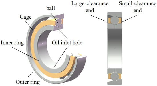
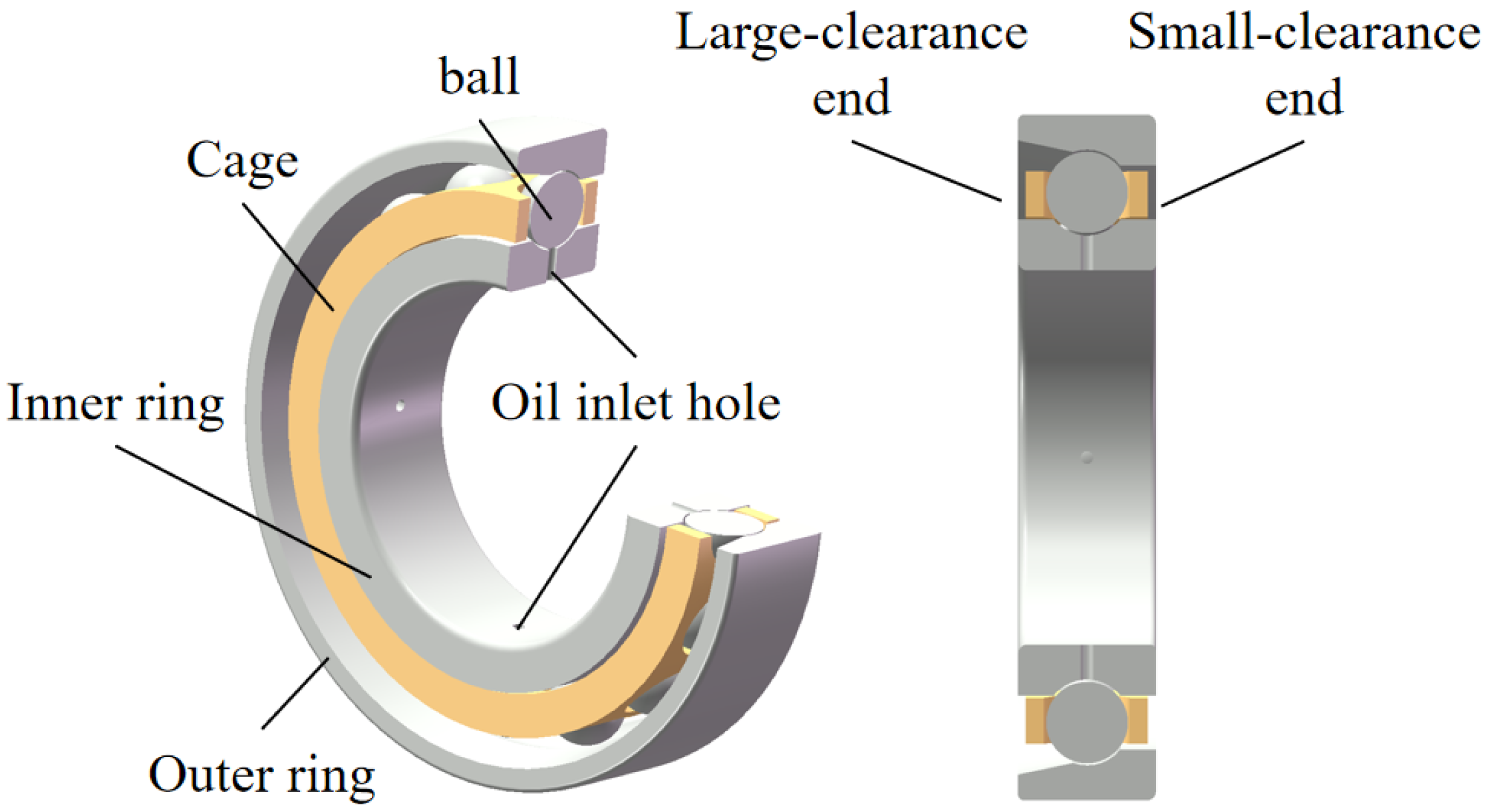
The investigated bearing is an SKF 7212 ACCBM angular contact ball bearing. Its main geometrical parameters are listed in Table 1. The bearing has an inner diameter of 60 mm, an outer diameter of 110 mm, a width of 22 mm, and 15 rolling elements. A simplified geometric model of the bearing was established for the numerical simulation, as shown in Figure 1. The model mainly consists of the inner ring, outer ring, rolling elements, cage, and oil inlet holes.
Table 1.
Geometrical parameters of the angular contact ball bearing.
Figure 1.
Simplified geometric model of the angular contact ball bearing.
In the under-race lubrication configuration, lubricant is supplied through oil inlet holes arranged on the inner ring. Four oil inlet holes with a diameter of 2 mm are located at the axial middle position of the bearing. The lubricant enters the bearing cavity through these inlet holes and is subsequently transported and redistributed by the rotating components. Due to the structural characteristics of the angular contact ball bearing, the two axial ends have different clearances. Therefore, the two sides are defined as the large-clearance end and the small-clearance end, respectively. The oil discharged from these two ends is used to evaluate the oil return characteristics of the bearing.
To ensure the connectivity of the fluid domain and avoid extremely small computational gaps between the rolling elements and raceways, the diameter of each rolling element was reduced to 95% of its original value. The selection of this scaling factor follows the study of Dai et al. [31], who investigated a 7212 angular contact ball bearing with the same nominal dimensions and rolling-element configuration and systematically compared rolling-element diameter scaling factors of 92%, 95%, and 98%. Their results indicated that a 95% scaling factor provides a reasonable compromise between global oil-transport prediction and computational cost. Therefore, the same scaling factor was adopted in the present model. It should be noted that this simplification may affect detailed bypass flow and local lubricant transport in the immediate vicinity of the ball–raceway gaps; thus, the present results are mainly interpreted in terms of macroscopic oil–air two-phase flow distribution and end oil return characteristics.
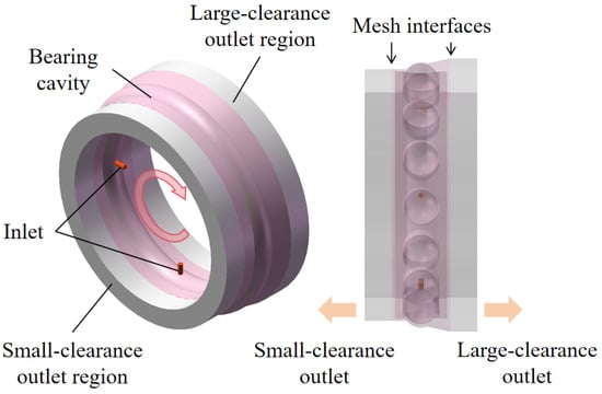
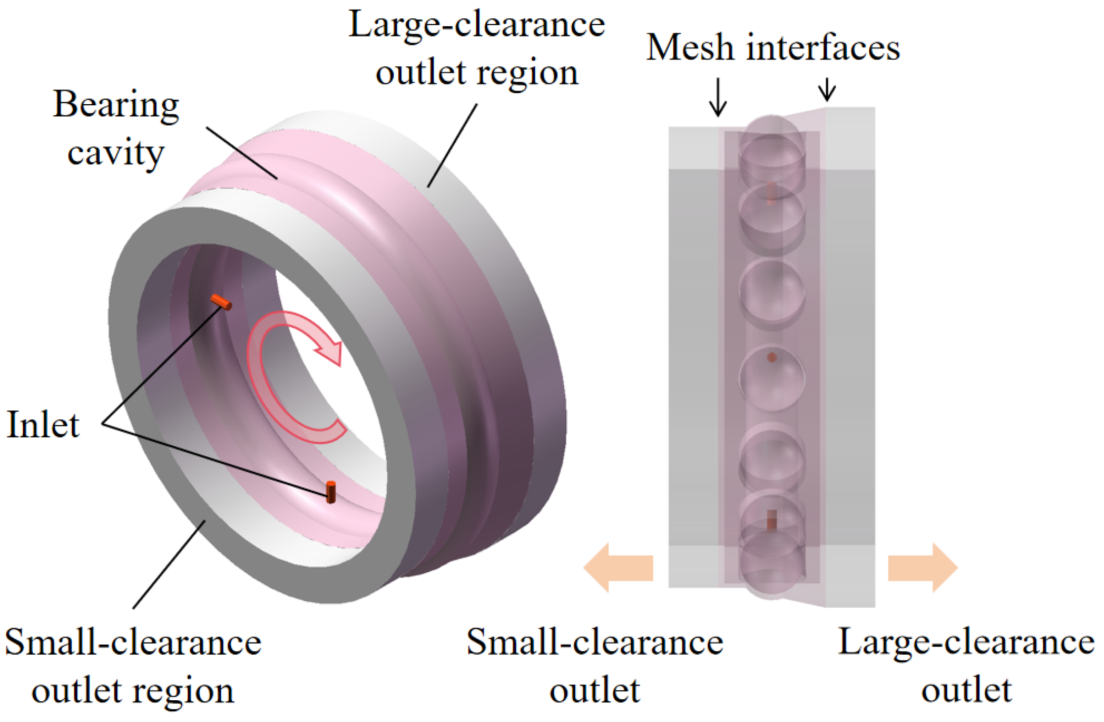
The computational domain for the oil–air flow simulation is shown in Figure 2. The domain mainly consists of the bearing cavity, oil inlet holes, and outlet regions at the two axial ends of the bearing. Lubricant enters the bearing cavity through the oil inlet holes on the inner ring and is transported by the rotating components. The oil–air mixture is finally discharged through the large-clearance outlet and the small-clearance outlet, and the corresponding outlet oil flow rates are used to evaluate the oil return characteristics. To describe the relative motion between the rolling elements and the surrounding flow field, the sliding mesh method was applied to the fluid domains associated with the rotating components. Mesh interfaces were used between the rotating and stationary domains to transfer flow information between different computational zones.
Figure 2.
Computational domain of the angular contact ball bearing under-race lubrication model. The red curved arrow indicates the rotational direction of the inner ring, and the orange arrows indicate the outlet flow directions.
2.3. Mesh Generation
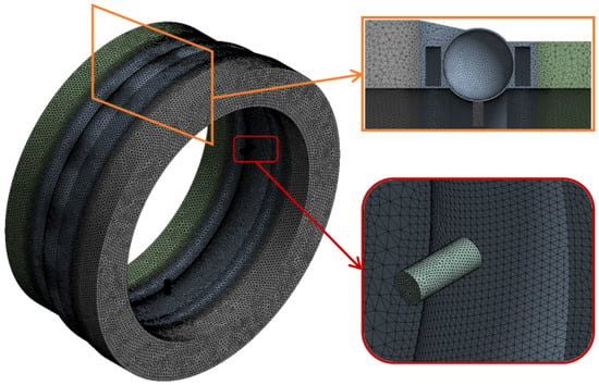
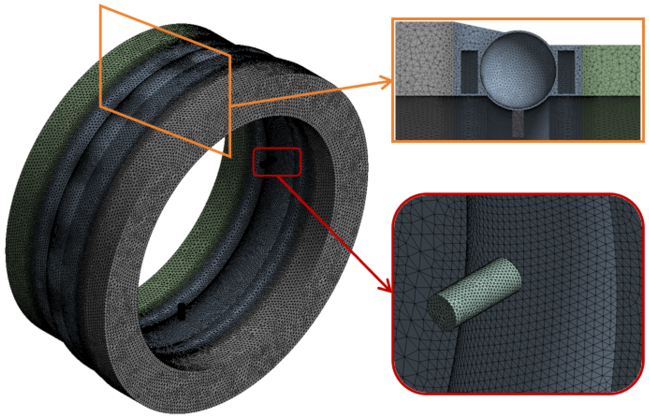
The mesh model of the computational domain is shown in Figure 3. All computational domains were discretized using tetrahedral meshes. Considering the complex flow characteristics in the bearing cavity, local mesh refinement was applied to the oil inlet holes, mesh interfaces between rotating and stationary domains, and rolling-element surfaces. The refinement near the oil inlet holes was used to accurately capture the injected oil distribution, while the refinement on the rolling-element surfaces was adopted to better resolve the near-wall lubricant transport. In addition, finer meshes were generated near the mesh interfaces to improve the exchange of flow information between the rotating and stationary regions.
Figure 3.
Mesh model of the computational domain. The orange and red boxes indicate enlarged views of the locally refined rolling-element/mesh-interface region and oil-inlet-hole region, respectively.
A mesh independence study was conducted using three systematically refined meshes containing 638,343, 1,127,773, and 2,326,293 cells. The corresponding oil return ratios at the large-clearance end were 98.56%, 97.17%, and 96.68%, respectively. When the mesh was refined from 1,127,773 to 2,326,293 cells, the predicted oil return ratio changed by only 0.50%, indicating that further mesh refinement had a limited influence on the numerical results. Therefore, the mesh containing 1,127,773 cells was selected for subsequent simulations considering both computational accuracy and efficiency.
2.4. Boundary Conditions and Numerical Settings
The oil inlet holes were specified as velocity inlets, while the outlets at the large-clearance and small-clearance ends were defined as pressure outlets. The lubricant used in the simulation was RIPP 555 aviation lubricating oil, with a density of 955 kg/m3 and a kinematic viscosity of 26.46 mm2/s. Air was assigned a constant density of 1.225 kg/m3 and a dynamic viscosity of 1.7894 × 10⁻⁵ Pa·s. The CFD model was formulated under an isothermal assumption, and the thermophysical properties of the oil and air were treated as constants. The model focuses on the macroscopic oil–air two-phase flow distribution and end oil return behavior rather than thermal effects, friction, or lubricant-film characteristics. Therefore, temperature-dependent variations in lubricant viscosity were not considered. The operating pressure was set to 101,325 Pa, and gravity was considered with an acceleration of 9.81 m/s2 in the negative y-direction.
Surface tension and wall adhesion were enabled in the VOF model to account for the interfacial interaction between the oil and air phases and the adhesion of lubricant to the solid surfaces. The realizable k–ε model was used to describe turbulence, together with standard wall functions for near-wall treatment.
The sliding mesh method was applied to the fluid domains associated with the rotating bearing components to describe their transient motion, whereas the outlet regions were treated as stationary domains. Mesh interfaces were used to exchange flow information between the rotating and stationary computational zones. The pressure–velocity coupling was solved using the SIMPLE algorithm. The Least Squares Cell Based method was used for gradient reconstruction, while PRESTO! was adopted for pressure discretization. The momentum equation was discretized using the Second Order Upwind scheme, and the Compressive scheme was used for the volume-fraction equation. The turbulent kinetic energy and turbulent dissipation rate were discretized using the First Order Upwind scheme. A First Order Implicit formulation was employed for transient calculations.
During the transient calculation, the time step was set to 1 × 10⁻⁴ s, and the maximum number of iterations per time step was 20. The convergence criterion for the continuity, velocity, turbulent kinetic energy, turbulent dissipation rate, and oil-volume-fraction residuals was set to 0.001. The initial computational domain was filled with air, corresponding to an air volume fraction of 1 and an oil volume fraction of 0.
The outer ring was fixed, while the inner ring rotated at the prescribed rotational speed. The rolling elements and cage moved circumferentially around the bearing axis, and their orbital rotational speed was determined from the inner-ring speed according to Equation (6). Following the kinematic treatment adopted by Dai et al. [31], the self-spin of the rolling elements was neglected to reduce computational complexity. No external load or preload was applied in the numerical model, and all bearing components were treated as rigid bodies without contact deformation.
The orbital rotational speed of the rolling elements and cage was determined from the inner-ring speed according to Equation (6):
where denotes the rotational speed of the inner ring, is the cage speed, and is the ball diameter, d is the pitch diameter of the bearing, and is the bearing contact angle.
2.5. Definition of Oil Return Ratio
To quantitatively characterize the oil discharge behavior of the angular contact ball bearing with under-race lubrication, the oil return ratios at the large-clearance and small-clearance ends are defined as the ratios of the corresponding outlet oil flow rates to the total inlet oil flow rate, respectively. The oil return ratio at the large-clearance end is expressed as:
where is the oil return ratio at the large-clearance end, is the outlet oil flow rate at the large-clearance end, and is the total inlet oil flow rate. Similarly, the oil return ratio at the small-clearance end, , is calculated using the outlet oil flow rate at the small-clearance end. The time required for the flow field to reach a dynamic steady state was approximately 0.15 s, 0.10 s, 0.10 s, and 0.05 s at rotational speeds of 3000, 4000, 5000, and 6000 rpm, respectively. After reaching the statistically stationary state, the outlet flow rates were averaged over the subsequent calculation period to obtain the oil return ratio. When oil leakage and transient oil accumulation in the bearing cavity are neglected, the sum of the oil return ratios at the two ends satisfies:
3. Validation of Numerical Model
3.1. Under-Race Lubrication Test Rig for the Angular Contact Ball Bearing
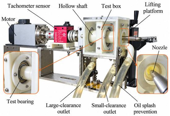
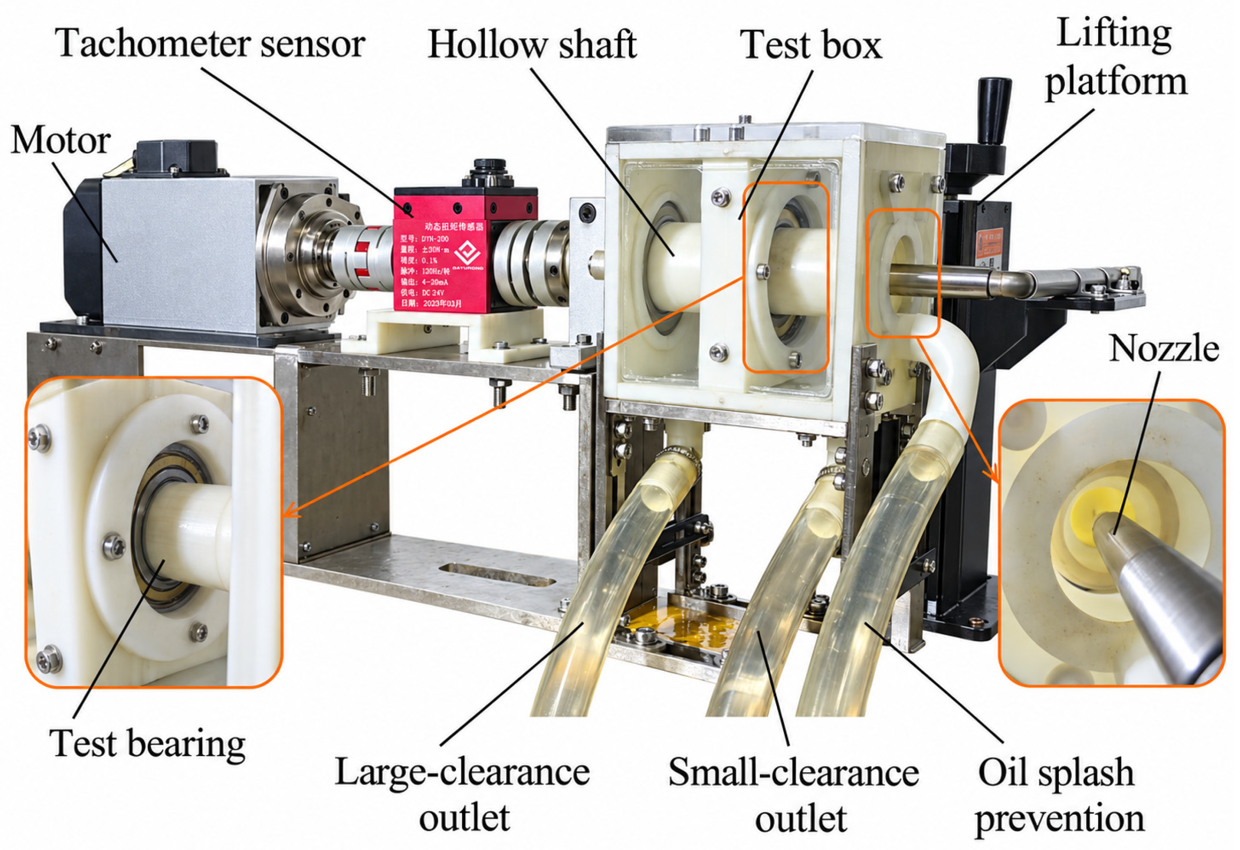
To validate the numerical model, an under-race lubrication test rig for the angular contact ball bearing was constructed, as shown in Figure 4. The test system mainly consists of an electric motor, coupling, tachometer sensor, hollow shaft, test box, nozzle, lifting platform, oil collection devices, electronic scale, and hydraulic pump station. The electric motor provides the driving torque for the test bearing. The rotational speed was measured using a tachometer sensor with an accuracy of ±0.1%. The collected lubricant mass was measured using an electronic scale with an accuracy of ±0.5 g, and the oil flow rate was controlled using a flow meter with an accuracy of ±1%. The lifting platform is used to adjust the nozzle position, ensuring accurate alignment between the nozzle and the oil injection location. The nozzle diameter is 1 mm. The hydraulic pump station, equipped with a gear pump, supplies RIPP 555 aviation lubricating oil to the test system.
Figure 4.
Photograph of the under-race lubrication test rig.
The test box was mainly fabricated using 3D printing technology, and transparent acrylic plates were installed on the front and rear sides to facilitate observation of the bearing operating state. The test bearing was mounted on a hollow shaft at the center of the chamber. The chamber was divided into two separate cavities to collect the lubricant discharged from the large-clearance and small-clearance ends, respectively. The lubricant collected in each cavity flowed out through the corresponding bottom outlet and was then collected in a beaker. Oil passages were drilled in the hollow shaft, allowing the lubricant to flow through the shaft and enter the bearing through the oil inlet holes on the inner ring.
During the experiment, the lubricant was injected through the nozzle into the hollow shaft cavity. Under centrifugal action, the lubricant entered the oil inlet holes on the inner ring and then flowed into the bearing cavity. Subsequently, the lubricant was discharged from the large-clearance and small-clearance ends and finally collected through the bottom outlets of the test box via transparent hoses.
Due to the limitations of the experimental conditions, only one representative oil flow rate, i.e., 105 L/h, was selected for model validation. In addition, the surface temperature of the bearing components was not measured in the present experiment. Therefore, the experimental validation mainly focused on the outlet oil return behavior of the bearing. During the test, the oil flow rate was kept constant at 105 L/h, and the rotational speed was varied from 3000 rpm to 6000 rpm in increments of 1000 rpm. For each operating condition, the bearing was first accelerated to the target rotational speed. After lubricant injection was initiated, the system was allowed to run for a short period until stable oil discharge was observed, and then the oil collection measurement was performed.
Before each measurement, an empty beaker was placed on the electronic scale, and the scale was tared so that only the collected lubricant mass was recorded. Two beakers were then placed simultaneously under the outlets of the transparent hoses corresponding to the large-clearance and small-clearance ends. After 10 s of oil collection, the lubricant mass in each beaker was measured and recorded. The collected lubricant was then removed, and the measurement was repeated three times under the same operating conditions.
The oil return ratio at each end was defined as the ratio of the lubricant amount collected at that end to the inlet lubricant amount during the same collection period. In the experiment, because the oil collection was performed after the discharge flow reached a stable state and the leakage was minimized, the total lubricant mass collected from the two ends was used to approximate the inlet lubricant mass during the collection period. Therefore, the oil return ratio at the large-clearance end was calculated using the mass ratio between the lubricant collected at the large-clearance end and the total lubricant collected from both ends. Since the collection time was identical for both outlets, the mass ratio was equivalent to the outlet flow-rate ratio. The final oil return ratio was obtained by averaging the results of three repeated measurements.
3.2. Comparison Between Experimental and Numerical Results
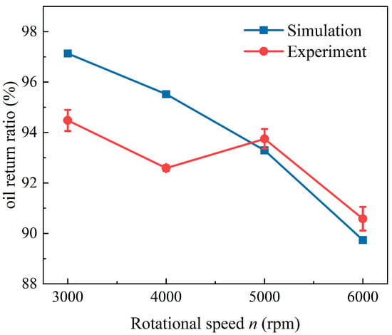
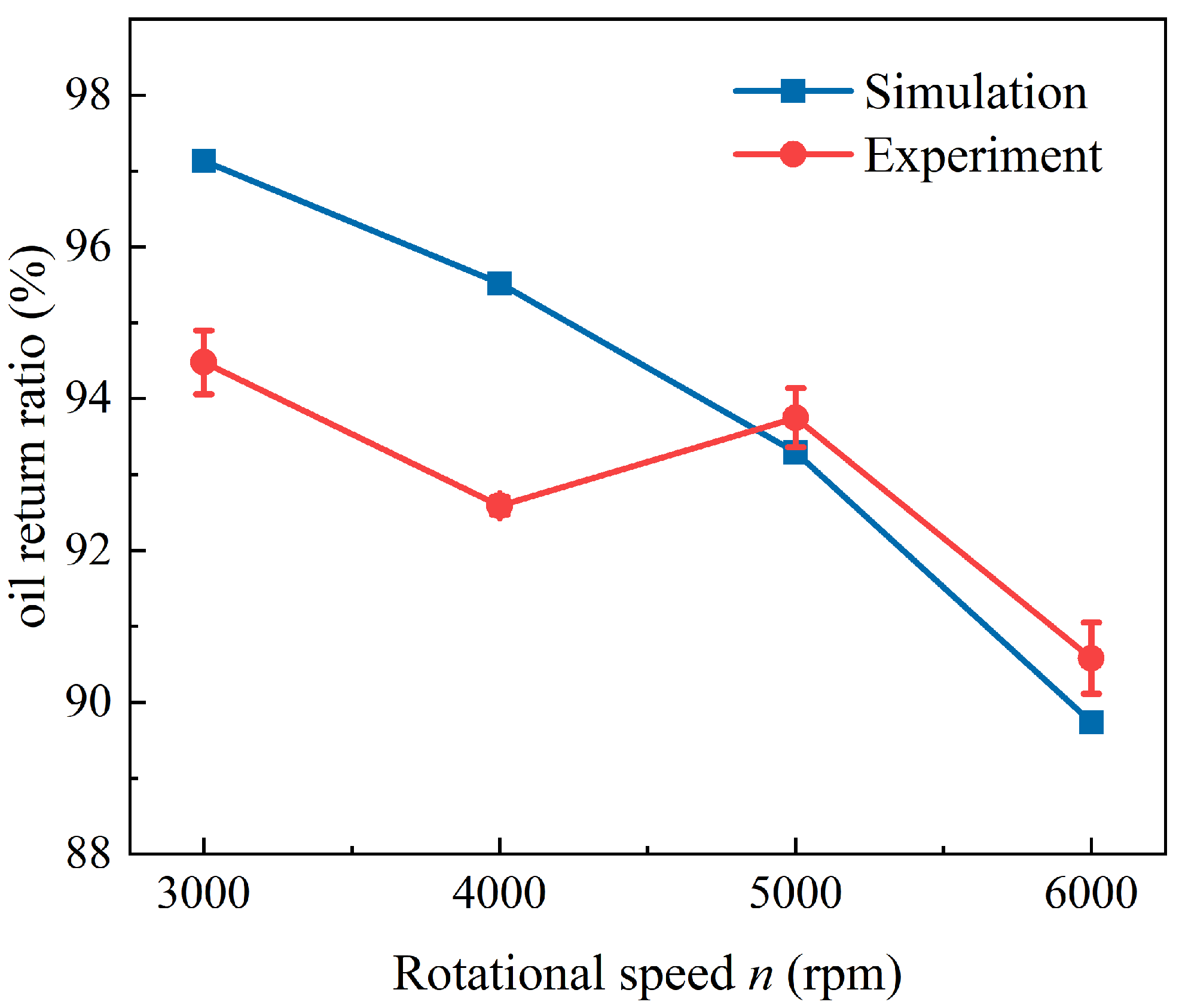
Figure 5 compares the numerical and experimental oil return ratios at the large-clearance end under different rotational speeds at Q = 105 L/h. The error bars in the experimental results represent the standard deviation obtained from three repeated measurements. Both results show an overall decreasing tendency with increasing rotational speed. The oil return ratio decreases from 97.13% to 89.74% in the simulation and from 94.48% to 90.58% in the experiment as the rotational speed increases from 3000 rpm to 6000 rpm. Although the experimental value at 5000 rpm is slightly higher than that at 4000 rpm, the overall trend and magnitude agree well with the numerical prediction.
Figure 5.
Comparison between numerical and experimental oil return ratios at the large-clearance end under different rotational speeds at Q = 105 L/h.
The numerical results show good agreement with the experimental measurements. The relative error was calculated based on the experimental value. The relative errors between the simulation and experiment are 2.80%, 3.17%, 0.49%, and 0.93% at 3000, 4000, 5000, and 6000 rpm, respectively. The maximum relative error is 3.17%, indicating that the numerical model can reasonably predict the oil return behavior at the bearing ends. Although the CFD model adopts an isothermal assumption with constant fluid properties, the maximum relative error remains within 3.17% over the investigated rotational-speed range of 3000–6000 rpm, indicating that this treatment provides an acceptable prediction of the end oil return behavior under the operating conditions considered in this study.
The discrepancies between the numerical and experimental results may be attributed to experimental uncertainties and simplifications in the numerical model. In the experiment, the oil collection process can be affected by oil adhesion on the chamber wall, oil splashing, residual oil in the transparent hoses, and small fluctuations in the oil supply system. In addition, the numerical model inevitably simplifies some geometric details and boundary conditions of the actual test rig. Despite these factors, the good agreement between the numerical and experimental results confirms that the numerical model is capable of capturing the main oil transport and discharge characteristics of the under-race lubrication system.
4. Results and Discussion
Since the present simulations were performed using a transient VOF-based model, the CFD results presented in this section were processed differently according to the type of data. The oil volume fraction contours represent instantaneous results extracted at 0.4 s after the flow field reached a dynamically stable state. The quantitative results, including the oil return ratio and surface-averaged oil volume fraction, were obtained from time-averaged values during the statistically stationary period.
The experimental validation presented in Section 3.2 was conducted for the oil return ratio under representative operating conditions. Due to the difficulty of measuring the internal oil–air two-phase flow distribution inside a high-speed bearing, the effects of operating parameters and inlet-hole configurations discussed in this section were investigated based on the validated numerical model.
4.1. Analysis of Oil–Air Two-Phase Flow Distribution
4.1.1. Effects of Oil Flow Rate and Rotational Speed on Oil Distribution
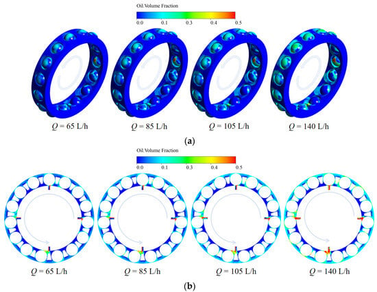
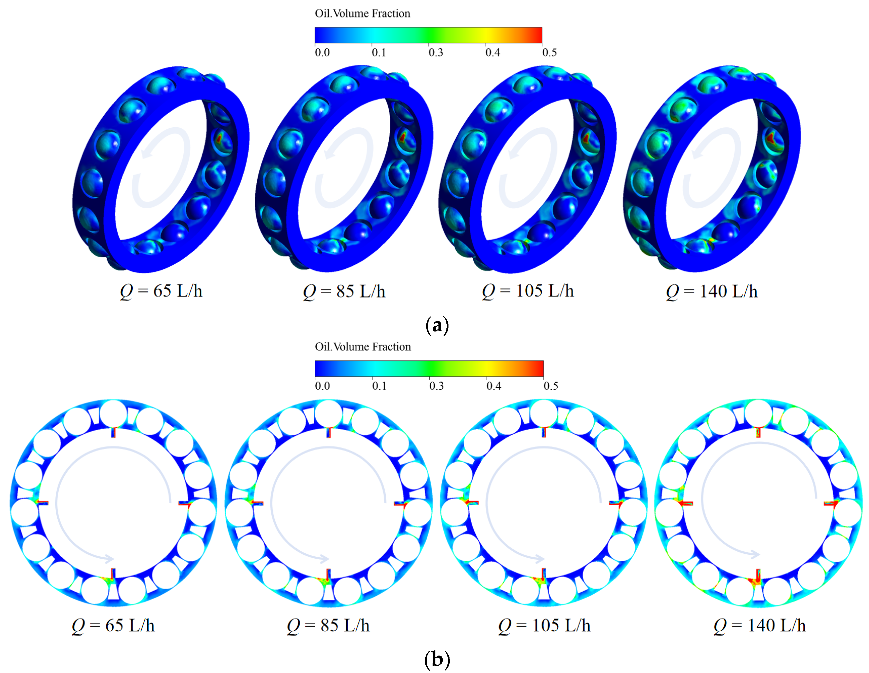
The influence of oil flow rate on the lubricant distribution is first examined at a fixed rotational speed of 3000 rpm, as shown in Figure 6. In Figure 6a, the oil volume fraction on the rolling element surfaces remains relatively low over most surface regions, while local oil-rich zones appear near the rolling element-raceway contact regions and on the downstream side of the rolling elements. As the oil flow rate increases from 65 L/h to 140 L/h, the amount of oil attached to the rolling element surfaces increases slightly. However, the expansion of high-oil-fraction regions is limited, especially when the oil flow rate exceeds 105 L/h. This indicates that increasing the inlet oil flow rate does not lead to a proportional increase in the oil retained on the rolling element surfaces.
Figure 6.
Oil distribution under different oil flow rates at n = 3000 rpm: (a) on rolling element surfaces; (b) in the bearing cavity.
The oil distribution in the bearing cavity exhibits a more noticeable response to the change in oil flow rate, as shown in Figure 6b. At 65 L/h, the oil phase is mainly concentrated near the inlet regions, and only a small amount of lubricant spreads along the circumferential direction. With increasing oil flow rate, the oil-rich regions near the inlets become more pronounced, and the circumferential oil distribution is enhanced to some extent. Nevertheless, even at 140 L/h, most of the bearing cavity is still characterized by a low oil volume fraction, and no large-scale oil accumulation is observed. This suggests that the injected oil is rapidly transported and redistributed by the rotating components, while excessive oil is removed from the local lubrication region. Therefore, increasing the oil flow rate improves the local oil supply level, but its contribution to the overall oil coverage on rolling element surfaces gradually weakens at high flow rates.
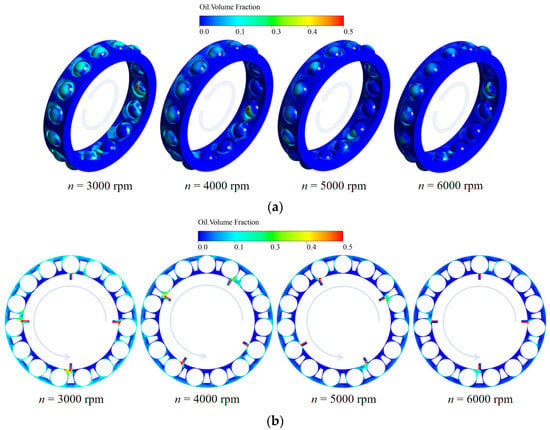
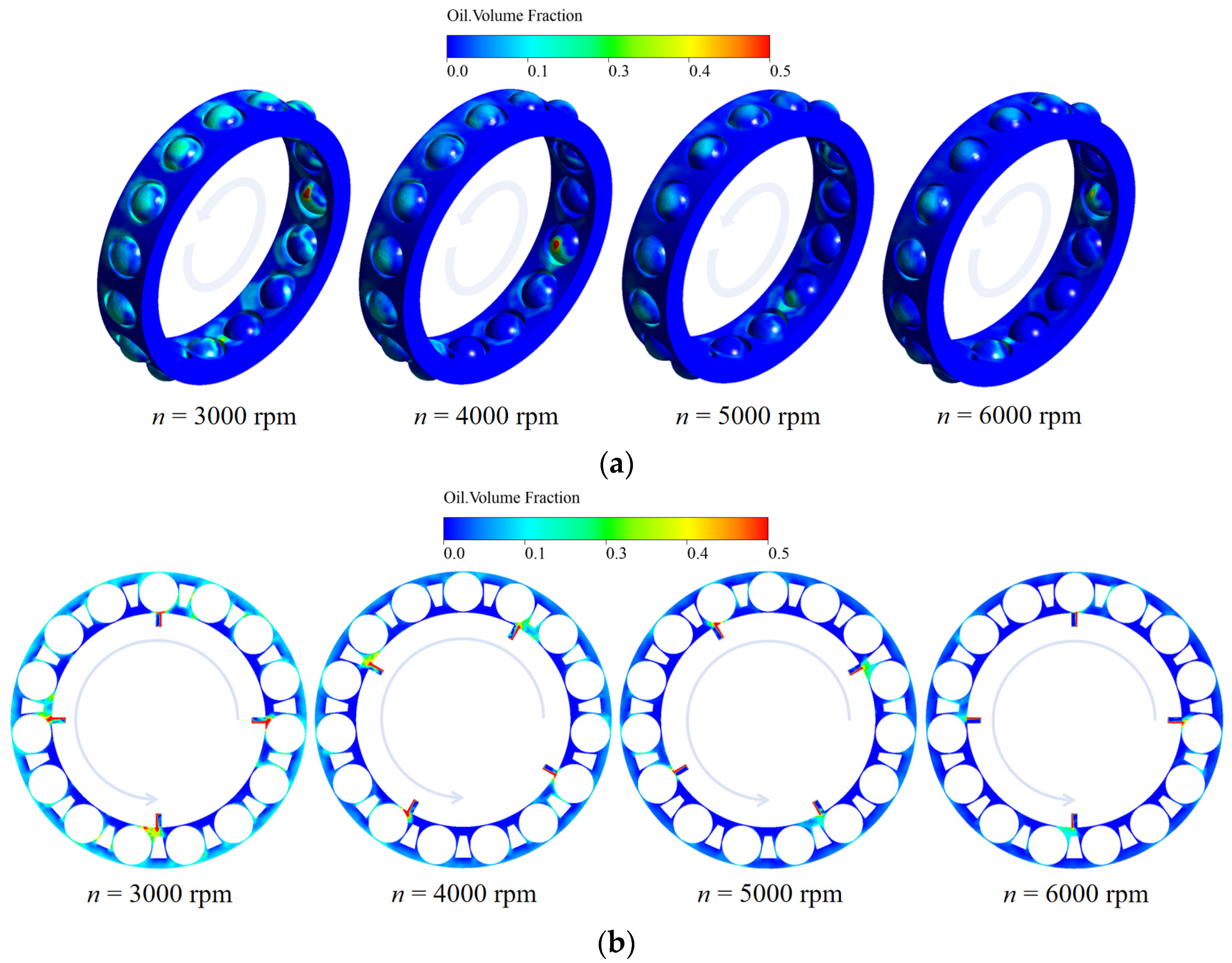
Compared with the effect of oil flow rate, rotational speed produces a larger variation in oil retention within the investigated range, as shown in Figure 7. When the oil flow rate is fixed at 105 L/h, increasing the rotational speed from 3000 rpm to 6000 rpm results in a clear reduction in oil volume fraction on the rolling element surfaces. At 3000 rpm, the lubricant is distributed over a relatively wide area, and several local oil-rich regions can be observed near the contact regions. As the speed increases to 4000 rpm and 5000 rpm, these oil-rich regions become smaller and less continuous. At 6000 rpm, most rolling element surfaces are covered by low oil volume fraction regions, indicating that the oil retention ability of the rolling elements is significantly weakened.
Figure 7.
Oil distribution under different rotational speeds at Q = 105 L/h: (a) on rolling element surfaces; (b) in the bearing cavity.
A similar tendency can be observed in the bearing cavity. At 3000 rpm, the oil phase spreads along part of the circumferential direction and forms local oil-rich regions near the inlet and between adjacent rolling elements. With increasing rotational speed, the circumferential oil distribution becomes more discontinuous, and the oil phase is mainly restricted to the inlet regions and limited local areas. This behavior is mainly attributed to the enhanced centrifugal effect and shear-driven airflow at high rotational speeds, which promote oil migration away from the rolling element surfaces and accelerate lubricant redistribution inside the bearing cavity. As a result, the amount of oil retained near the rolling elements decreases markedly under high-speed conditions.
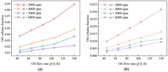
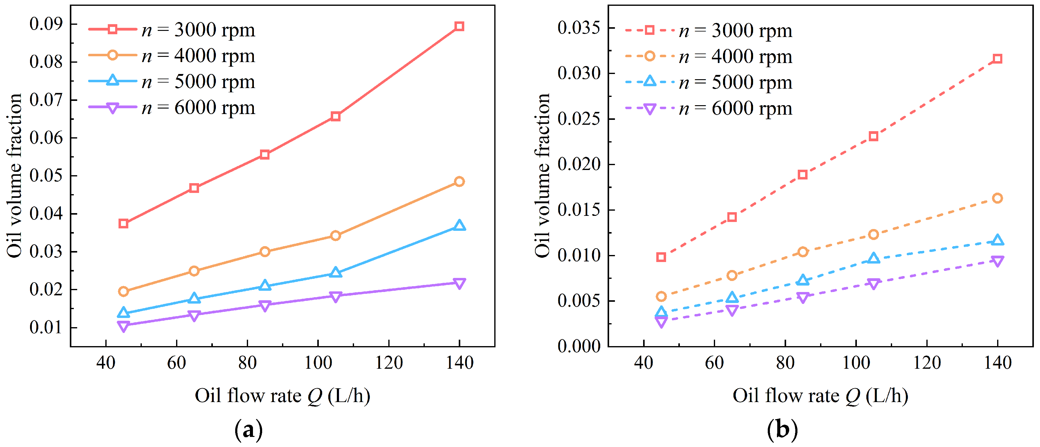
The contour results in Figure 6 and Figure 7 are further quantified by the average oil volume fraction on the rolling element and cage surfaces, as shown in Figure 8. The rolling element surfaces retain considerably more lubricant than the cage surface under all operating conditions. For the rolling elements, the average oil volume fraction increases continuously with oil flow rate, confirming that a higher inlet flow rate enhances the oil supply to the rolling elements. For example, at 3000 rpm, the oil volume fraction increases from approximately 0.037 at 65 L/h to about 0.089 at 140 L/h. However, the growth rate becomes smaller at higher rotational speeds, indicating that the oil supply improvement caused by increasing flow rate is partly suppressed by high-speed-induced oil removal.
Figure 8.
Average oil volume fraction on bearing component surfaces under different operating conditions: (a) rolling element surfaces; (b) cage surface.
The cage surface shows the same general trend but with a much lower oil volume fraction. Its oil volume fraction increases with oil flow rate and decreases with rotational speed, but the magnitude is much smaller than that on the rolling element surfaces. This difference indicates that the rolling elements are directly involved in oil entrainment and transport near the raceway contact regions, whereas the cage surface is mainly wetted by secondary oil flow, splash, and local redistribution in the bearing cavity. Therefore, the cage surface is more sensitive to the oil redistribution process and less capable of retaining lubricant, especially under high-speed operating conditions. These quantitative results indicate that the surface oil retention on the bearing components is governed by the competition between lubricant supply and high-speed-induced oil removal. Increasing the oil flow rate increases the amount of oil retained on the rolling element and cage surfaces, whereas increasing rotational speed promotes oil redistribution and reduces the corresponding average oil volume fraction.
4.1.2. Effects of Axial Position of Oil Inlet Holes on Oil Distribution
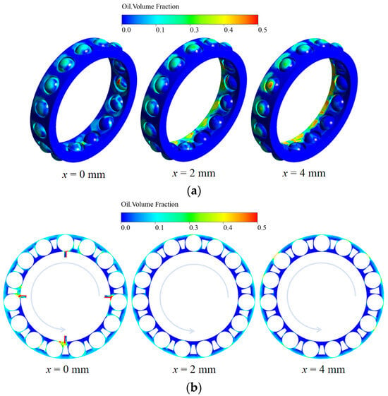
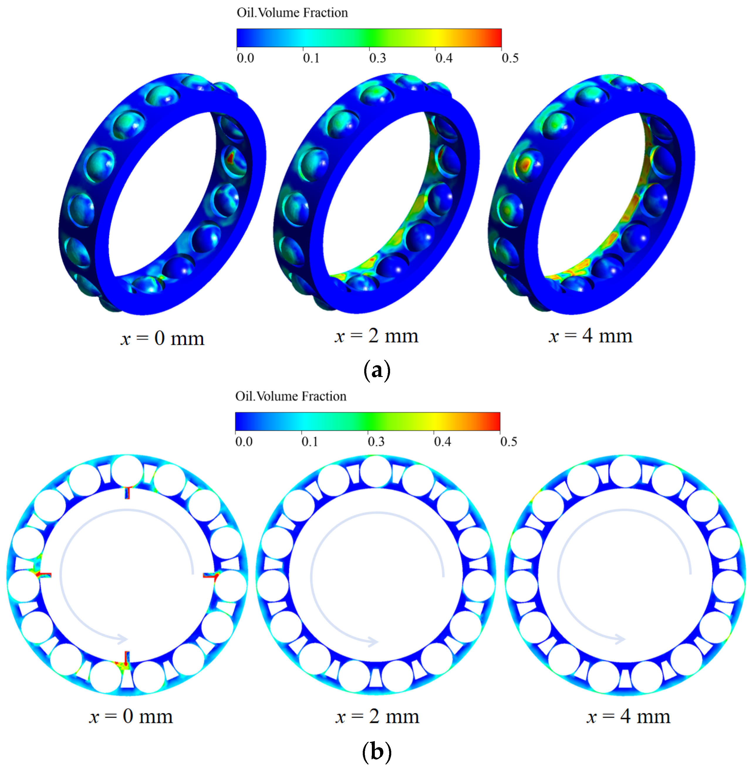
The axial position of the oil inlet holes changes the initial injection location of lubricant and therefore affects its subsequent distribution inside the bearing cavity. Figure 9 shows the oil distribution under different axial positions of the oil inlet holes at n = 3000 rpm and Q = 105 L/h. Here, x denotes the axial offset distance of the oil inlet holes from the bearing mid-plane toward the small-clearance end.
Figure 9.
Oil distribution under different axial positions of the oil inlet holes at n = 3000 rpm and Q = 105 L/h: (a) on rolling element surfaces; (b) in the bearing cavity.
When x = 0 mm, the inlet holes are located near the bearing mid-plane, and the lubricant is distributed relatively uniformly around the rolling elements. Local oil-rich regions mainly appear near the rolling element-raceway contact regions and on the downstream side of the rolling elements. When the inlet holes are shifted toward the small-clearance end, the oil phase becomes more locally concentrated. In particular, at x = 4 mm, a more evident oil-rich region appears near the lower part of the bearing, suggesting that the offset inlet position promotes local oil enrichment in the region directly affected by the injected oil.
The bearing cavity distribution in Figure 9b shows that the influence of inlet-hole position on the overall cavity oil distribution is relatively limited. For the three inlet positions, the oil phase is mainly located near the inlet regions and along limited circumferential regions, while most of the bearing cavity remains at a low oil volume fraction. As the inlet holes move toward the small-clearance end, the local oil-rich region near the inlet becomes slightly more concentrated, but no large-scale oil accumulation is formed. This indicates that the axial offset of the inlet holes mainly affects local oil enrichment rather than significantly increasing the overall oil content in the bearing cavity.
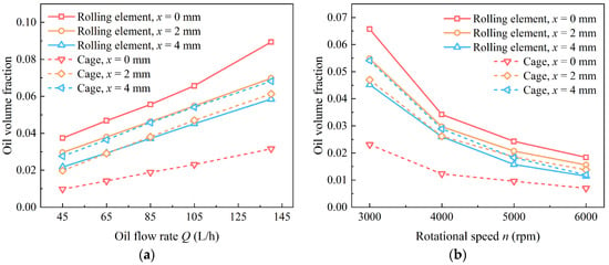
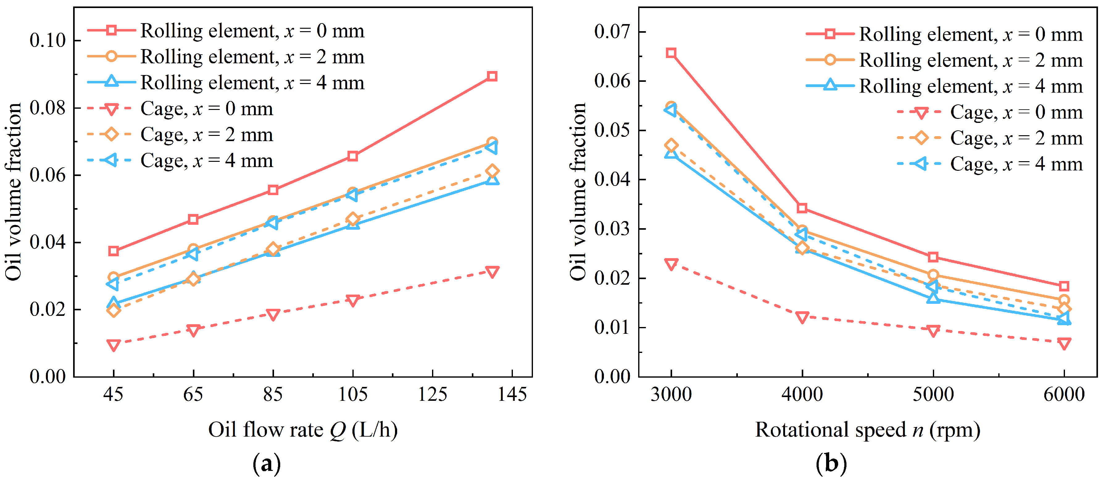
The averaged results in Figure 10 reveal a more detailed component-dependent effect of inlet-hole offset. Although Figure 9 shows local oil enrichment when the inlet holes are shifted toward the small-clearance end, Figure 10a indicates that the average oil volume fraction on the rolling element surfaces is highest at x = 0 mm over the entire flow-rate range. When x increases to 2 mm and 4 mm, the average oil volume fraction on the rolling element surfaces decreases. Therefore, the local oil-rich region caused by inlet offset does not necessarily improve the overall oil supply on the rolling elements.
Figure 10.
Effect of axial position of oil inlet holes on the average oil volume fraction on rolling element and cage surfaces: (a) variation with oil flow rate at n = 3000 rpm; (b) variation with rotational speed at Q = 105 L/h.
In contrast, the cage surface exhibits a different response. The oil volume fraction on the cage surface generally increases when the inlet holes are shifted toward the small-clearance end, especially under low-speed or high-flow-rate conditions. This suggests that the offset inlet position promotes oil attachment and retention on the cage surface. When the lubricant enters closer to the small-clearance end, the restricted axial clearance strengthens the interaction between the injected oil, cage, and surrounding flow field. Consequently, more lubricant is intercepted by or attached to the cage surface, while the oil supplied to the rolling element surfaces becomes less uniformly distributed.
The speed-dependent results in Figure 10b further show that the oil volume fraction on both rolling element and cage surfaces decreases with increasing rotational speed for all inlet positions. The rolling element surfaces still maintain the highest oil volume fraction at x = 0 mm, whereas the cage surface tends to retain more oil when the inlet holes are offset toward the small-clearance end. These results indicate that the axial inlet position changes the redistribution of lubricant between different bearing components. For the present bearing configuration, placing the inlet holes near the bearing mid-plane results in a higher average oil volume fraction on the rolling element surfaces, whereas shifting the inlet holes toward the small-clearance end promotes oil retention on the cage surface.
4.1.3. Effects of Oil Inlet Hole Diameter on Oil Distribution
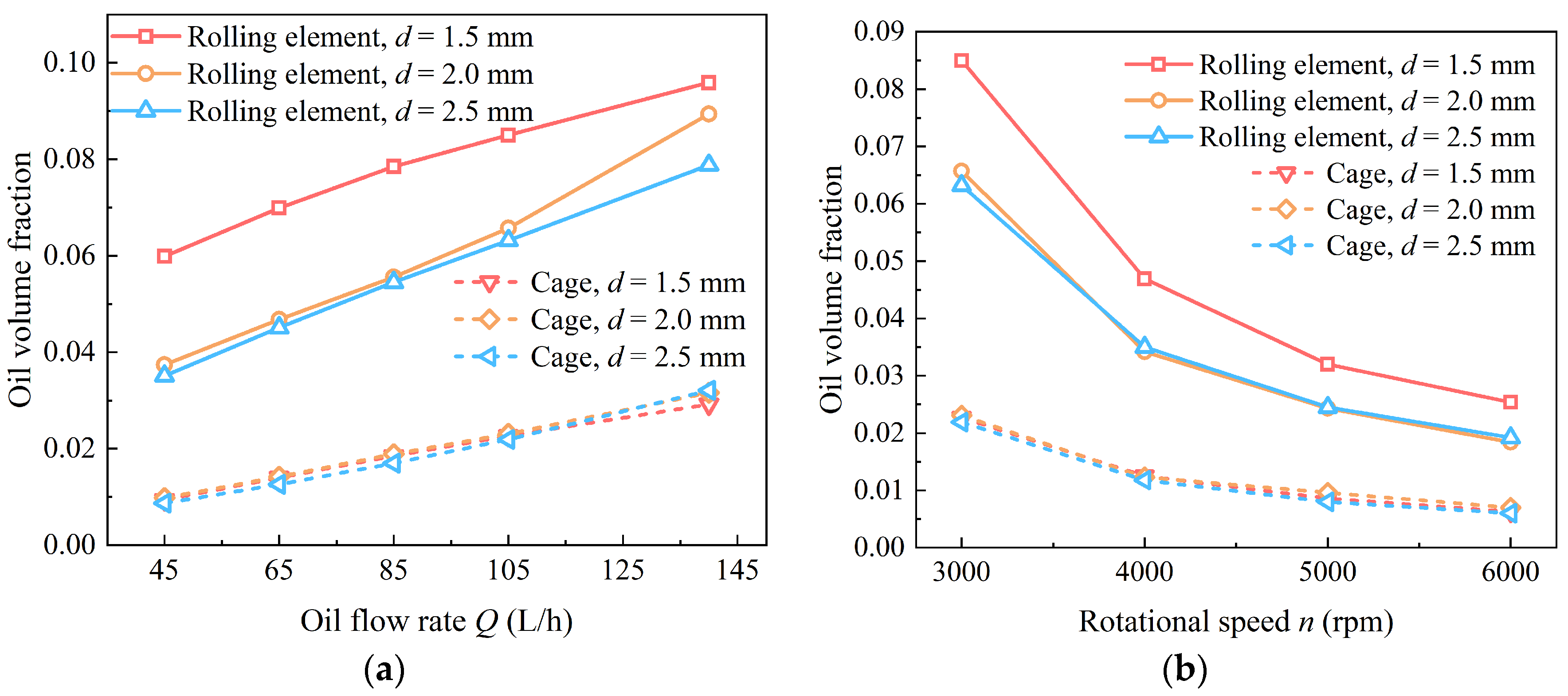
The effect of oil inlet hole diameter on the average oil volume fraction is shown in Figure 11. Unlike the axial inlet position, which mainly changes the axial injection location, the inlet hole diameter directly affects the injection velocity and jet penetration under the same inlet flow rate.
Figure 11.
Effect of oil inlet hole diameter on the average oil volume fraction on rolling element and cage surfaces: (a) variation with oil flow rate at n = 3000 rpm; (b) variation with rotational speed at Q = 105 L/h.
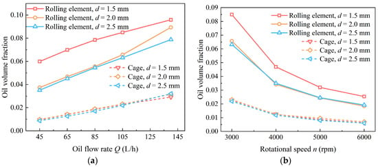
As shown in Figure 11a, the oil volume fraction on both rolling element and cage surfaces increases with oil flow rate for all inlet hole diameters. Within the investigated diameter range, the rolling element surfaces obtain the highest oil volume fraction when d = 1.5 mm. As the inlet hole diameter increases to 2.0 mm and 2.5 mm, the oil volume fraction on the rolling element surfaces decreases. This can be explained by the variation in injection characteristics. Under the same flow rate, a smaller inlet hole produces a higher injection velocity, which enhances the penetration ability of the oil jet and promotes direct interaction between the supplied oil and the rolling elements. In contrast, a larger inlet hole reduces the injection velocity, making the supplied oil more likely to disperse in the bearing cavity before effectively reaching the rolling element surfaces.
The cage surface is less sensitive to the inlet hole diameter. Its oil volume fraction is much lower than that on the rolling element surfaces, and the difference among different hole diameters remains relatively small. This indicates that oil attachment on the cage surface is mainly governed by splash, secondary flow, and local redistribution in the bearing cavity rather than by the inlet jet penetration alone.
The rotational-speed results in Figure 11b show that increasing speed significantly reduces oil retention on both rolling element and cage surfaces. Nevertheless, the rolling element surfaces still show the highest oil volume fraction at d = 1.5 mm over the investigated speed range. This confirms that a smaller inlet hole diameter can maintain stronger jet penetration and more effective oil delivery to the rolling elements even under high-speed conditions. Within the investigated diameter range, reducing the inlet-hole diameter increases the average oil volume fraction on the rolling element surfaces, whereas its influence on oil retention on the cage surface is relatively limited.
4.1.4. Effects of Number of Oil Inlet Holes on Oil Distribution
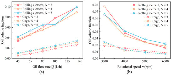
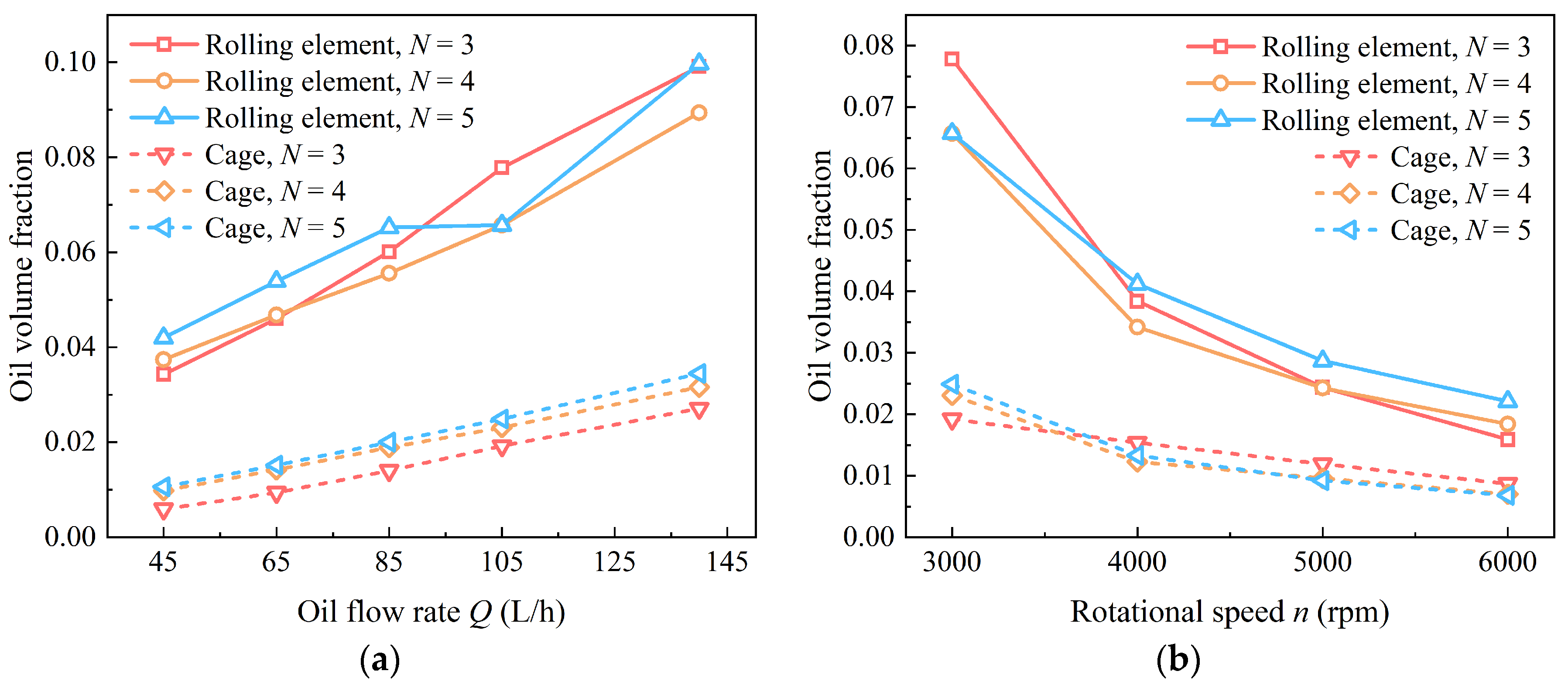
Figure 12 shows the effect of the number of oil inlet holes on the average oil volume fraction on rolling element and cage surfaces. When the total oil flow rate is maintained constant, increasing the number of inlet holes reduces the average flow rate and injection velocity through each individual hole, while improving the circumferential distribution of lubricant supply around the inner ring.
Figure 12.
Effect of the number of oil inlet holes on the average oil volume fraction on rolling element and cage surfaces: (a) variation with oil flow rate at n = 3000 rpm; (b) variation with rotational speed at Q = 105 L/h.
As shown in Figure 12a, increasing the oil flow rate improves the oil volume fraction on both rolling element and cage surfaces for all inlet-hole numbers. For the rolling element surfaces, increasing the number of inlet holes generally enhances the average oil volume fraction, particularly at low and moderate flow rates. This indicates that multiple inlet holes improve the circumferential uniformity of oil supply and allow more lubricant to reach the rolling elements. At higher flow rates, however, the difference among different inlet-hole numbers becomes less regular, suggesting that the interaction among multiple oil streams, rotating components, and internal airflow becomes more complex when the oil supply level is high.
The cage surface shows a similar increasing trend with oil flow rate, but its oil volume fraction remains much lower than that on the rolling element surfaces. A larger number of inlet holes generally promotes oil attachment on the cage surface by increasing the spatial coverage of supplied oil and enhancing oil impingement, splash, and redistribution around the cage pockets. This effect becomes more visible when the oil flow rate is relatively high.
The results in Figure 12b show that oil retention decreases with increasing rotational speed. As the rotational speed increases from 3000 rpm to 6000 rpm, the oil volume fraction on both rolling element and cage surfaces decreases rapidly. For the rolling elements, N = 5 maintains a relatively higher oil volume fraction at most rotational speeds, indicating that increasing the number of inlet holes can partly compensate for the reduction in oil retention caused by high-speed operation. For the cage surface, however, the differences among different inlet-hole numbers become smaller at high rotational speeds, implying that strong airflow and centrifugal transport dominate the cage surface oil distribution under high-speed conditions.
Taken together, the inlet-hole diameter and number affect the internal oil distribution through different mechanisms. A smaller inlet-hole diameter increases the jet velocity and enhances lubricant penetration toward the rolling elements, whereas increasing the number of inlet holes changes the circumferential distribution of the supplied oil. Under high-speed conditions, however, the effects of these inlet parameters on surface oil retention become less pronounced because centrifugal transport and shear-driven airflow increasingly govern lubricant redistribution.
4.2. Oil Return Characteristics Analysis
4.2.1. Effects of Oil Flow Rate and Rotational Speed
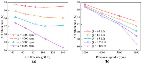
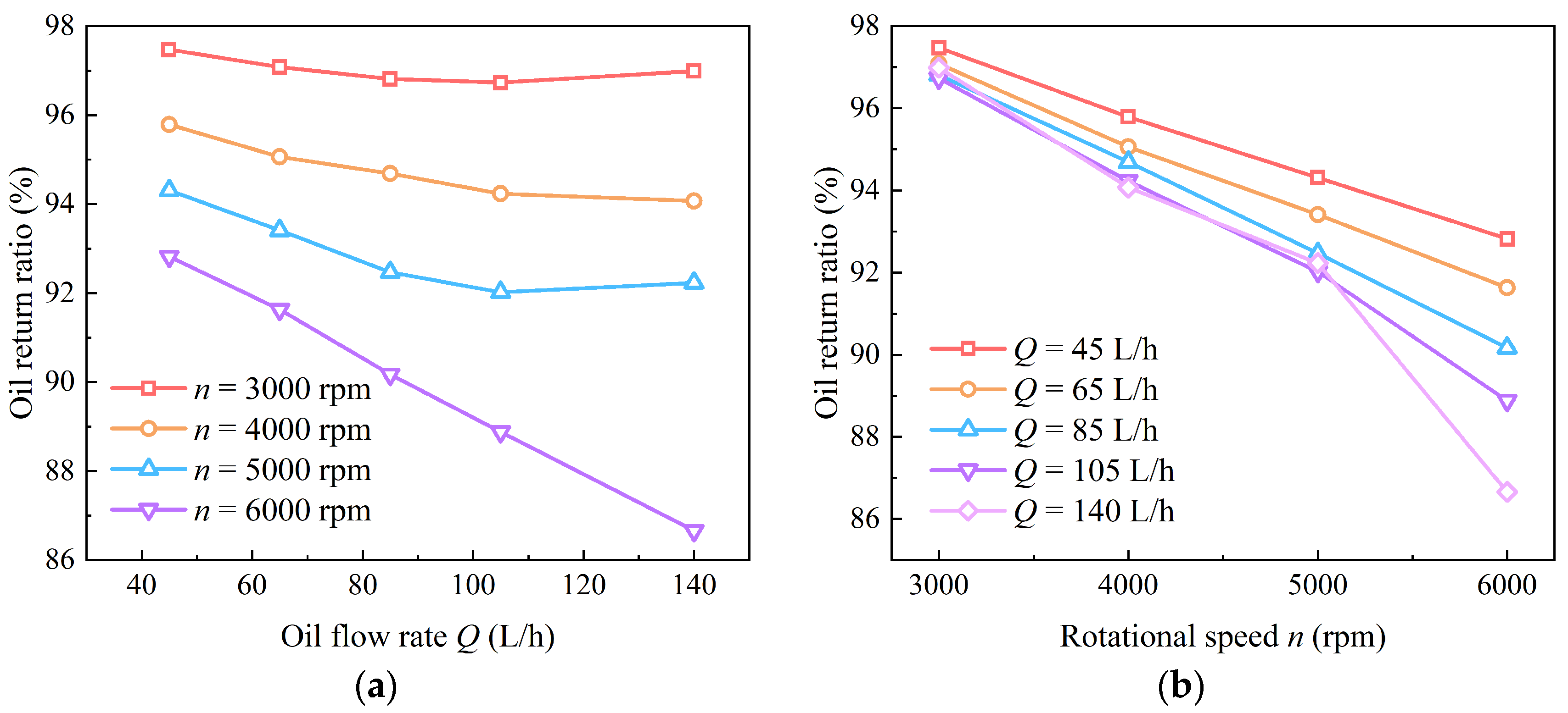
Figure 13 presents the oil return ratio at the large-clearance end under different oil flow rates and rotational speeds. The oil return ratio is defined as the ratio of the outlet oil flow rate at the large-clearance end to the inlet oil flow rate. Therefore, it characterizes the fraction of the supplied oil discharged through the large-clearance end rather than the absolute outlet flow rate.
Figure 13.
Oil return ratio at the large-clearance end under different operating conditions: (a) variation with oil flow rate; (b) variation with rotational speed.
As shown in Figure 13a, the oil return ratio at the large-clearance end remains at a relatively high level under all operating conditions, indicating that the large-clearance end is the dominant discharge side in the present bearing configuration. At a given rotational speed, the oil return ratio generally decreases with increasing oil flow rate. At 3000 rpm, the oil return ratio remains above 96% and changes only slightly as the oil flow rate increases. However, at higher rotational speeds, especially at 6000 rpm, the decrease becomes more pronounced. This indicates that increasing the inlet oil flow rate does not lead to a proportional increase in the fraction of oil discharged from the large-clearance end.
The influence of rotational speed is more evident in Figure 13b. At a fixed oil flow rate, the oil return ratio decreases as the rotational speed increases from 3000 rpm to 6000 rpm, and the decrease becomes larger at higher oil flow rates. When Q = 45 L/h, the oil return ratio decreases from approximately 97.5% at 3000 rpm to about 93% at 6000 rpm. In contrast, when Q = 140 L/h, it decreases from approximately 97% to about 86.5% over the same speed range. This suggests that high rotational speed weakens the relative discharge proportion through the large-clearance end, particularly under high-flow-rate conditions.
This behavior is closely related to oil redistribution inside the bearing cavity. As discussed in the oil–air two-phase flow distribution analysis, increasing rotational speed enhances centrifugal transport and shear-driven airflow, which accelerates circumferential redistribution of the lubricant and reduces oil retention on the rolling element and cage surfaces. Meanwhile, the intensified internal airflow and oil–air interaction may promote part of the lubricant to migrate toward other regions of the bearing cavity or toward the small-clearance end. When the inlet flow rate is high, the larger amount of injected oil further strengthens local oil–air mixing and flow disturbance, making the outlet flow distribution more sensitive to rotational speed.
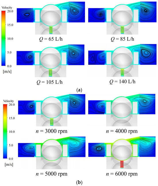
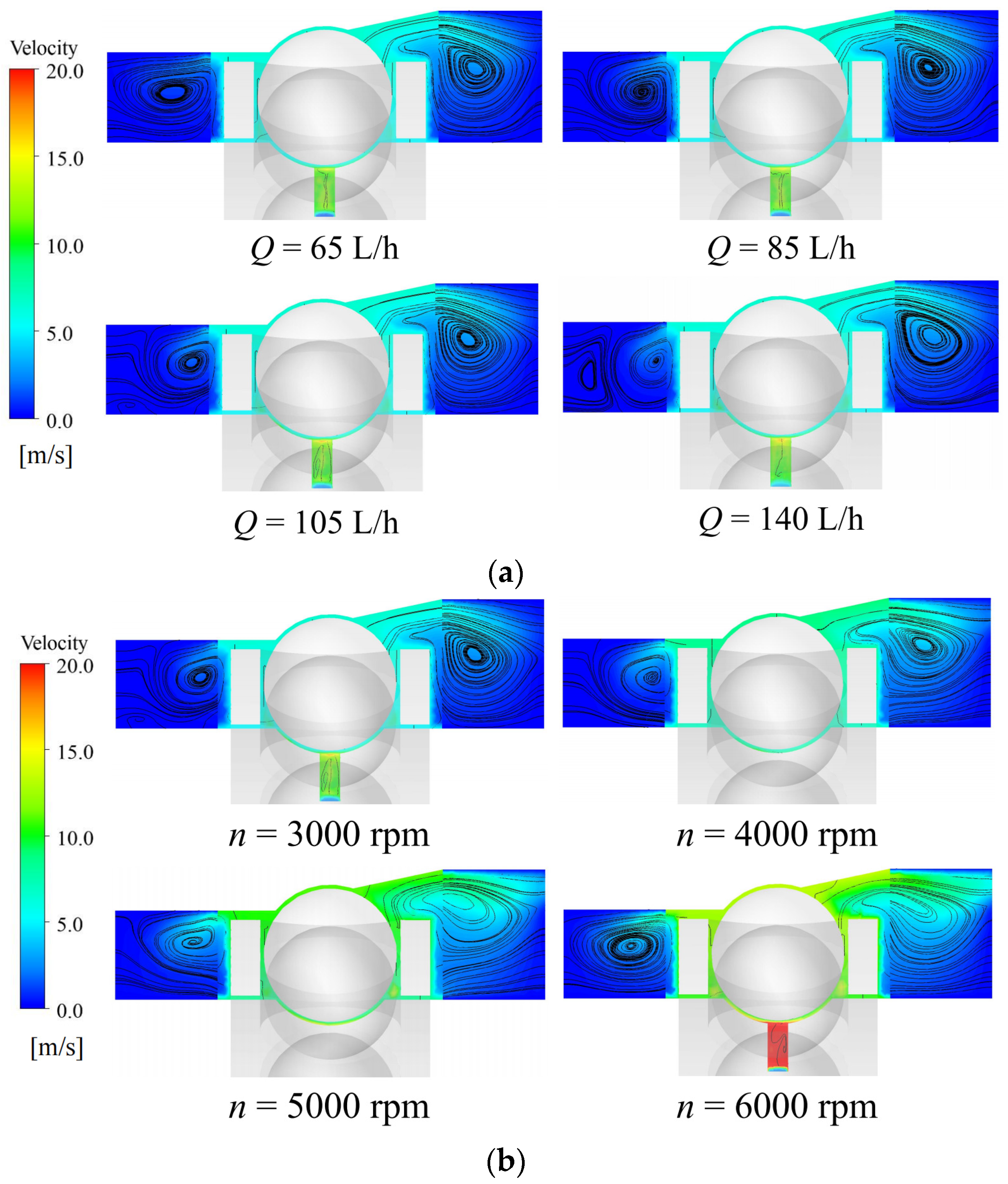
The corresponding velocity and streamline distributions in Figure 14 provide a flow-field explanation for the variation in Figure 13. Under different oil flow rates, vortices are formed on both sides of the rolling element, indicating that the oil–air mixture undergoes local circulation and redistribution rather than flowing directly toward the outlet regions. With increasing oil flow rate, the inlet jet becomes stronger, the local high-velocity region near the inlet expands, and the streamlines near the rolling element and outlet regions become more disturbed. These changes enhance local oil–air mixing and cause part of the lubricant to be involved in internal recirculation, thereby reducing the fraction discharged from the large-clearance end.
Figure 14.
Velocity and streamline distributions in the bearing cavity under different operating conditions: (a) effect of oil flow rate; (b) effect of rotational speed.
As shown in Figure 14b, increasing the rotational speed from 3000 rpm to 6000 rpm markedly increases the velocity level around the rolling element and in the inlet region. The high-velocity region becomes more pronounced, and the vortices on both sides of the rolling element are strengthened. At high rotational speeds, stronger shear-driven airflow and centrifugal transport intensify circumferential redistribution of the oil–air mixture. Consequently, the oil flow path becomes more complex, and the preferential discharge path toward the large-clearance outlet is disturbed. Therefore, the decrease in the large-clearance-end oil return ratio can be attributed to the intensified internal circulation and oil–air redistribution in the bearing cavity.
4.2.2. Effects of Axial Position of Oil Inlet Holes
The axial position of the oil inlet holes directly changes the initial injection location and the subsequent axial transport path of the lubricant. Figure 15 shows the effect of inlet-hole axial position on the oil return ratio at the large-clearance end. Here, x denotes the axial offset distance of the oil inlet holes from the bearing mid-plane toward the small-clearance end.
Figure 15.
Effect of axial position of oil inlet holes on the oil return ratio at the large-clearance end: (a) variation with oil flow rate at n = 3000 rpm; (b) variation with rotational speed at Q = 105 L/h.
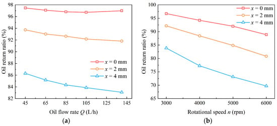
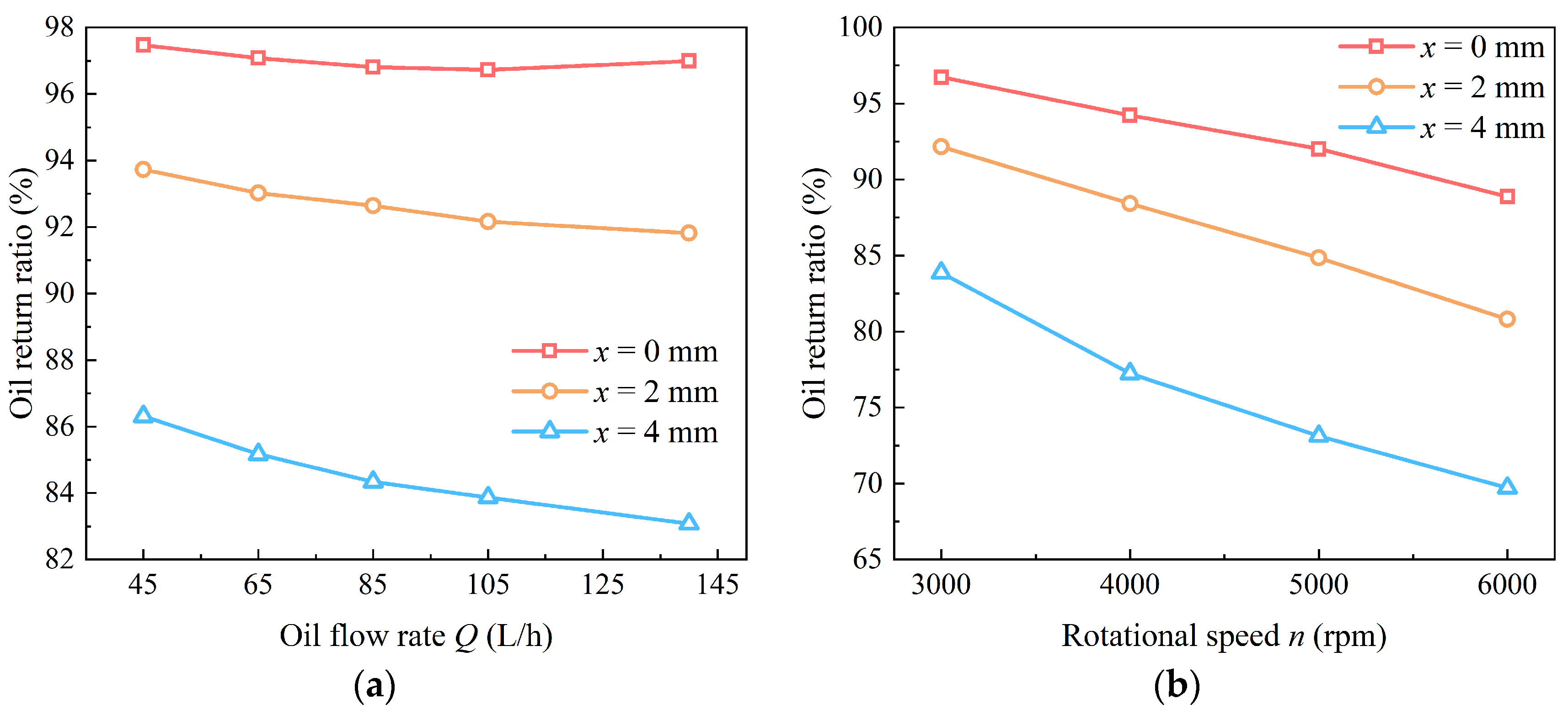
As shown in Figure 15a, shifting the inlet holes toward the small-clearance end significantly reduces the oil return ratio at the large-clearance end. When x = 0 mm, the oil return ratio remains approximately 97% over the whole flow-rate range, indicating that most of the supplied oil is discharged from the large-clearance end. When x increases to 2 mm, the oil return ratio decreases to approximately 92–94%. A further increase to x = 4 mm results in a more significant reduction, with the oil return ratio decreasing to about 83–86%. This indicates that the axial position of the inlet holes strongly affects the outlet flow allocation between the two bearing ends.
Compared with the inlet-hole axial position, the influence of oil flow rate is relatively weak. At a fixed inlet position, the oil return ratio only decreases slightly with increasing oil flow rate. This suggests that the inlet-hole position mainly determines the axial discharge path of the injected lubricant, whereas increasing the oil flow rate mainly changes the local supply intensity and oil–air mixing inside the bearing cavity.
The speed-dependent results in Figure 15b further show that the oil return ratio decreases with increasing rotational speed for all inlet positions. This decrease is particularly significant when the inlet holes are offset toward the small-clearance end. At x = 0 mm, the oil return ratio decreases from about 97% at 3000 rpm to approximately 89% at 6000 rpm. In comparison, at x = 4 mm, it decreases from about 84% to nearly 70% over the same speed range. This indicates that high-speed rotation amplifies the influence of inlet-hole offset on the oil return behavior.
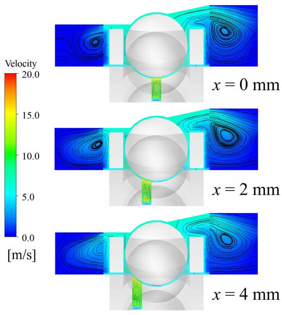
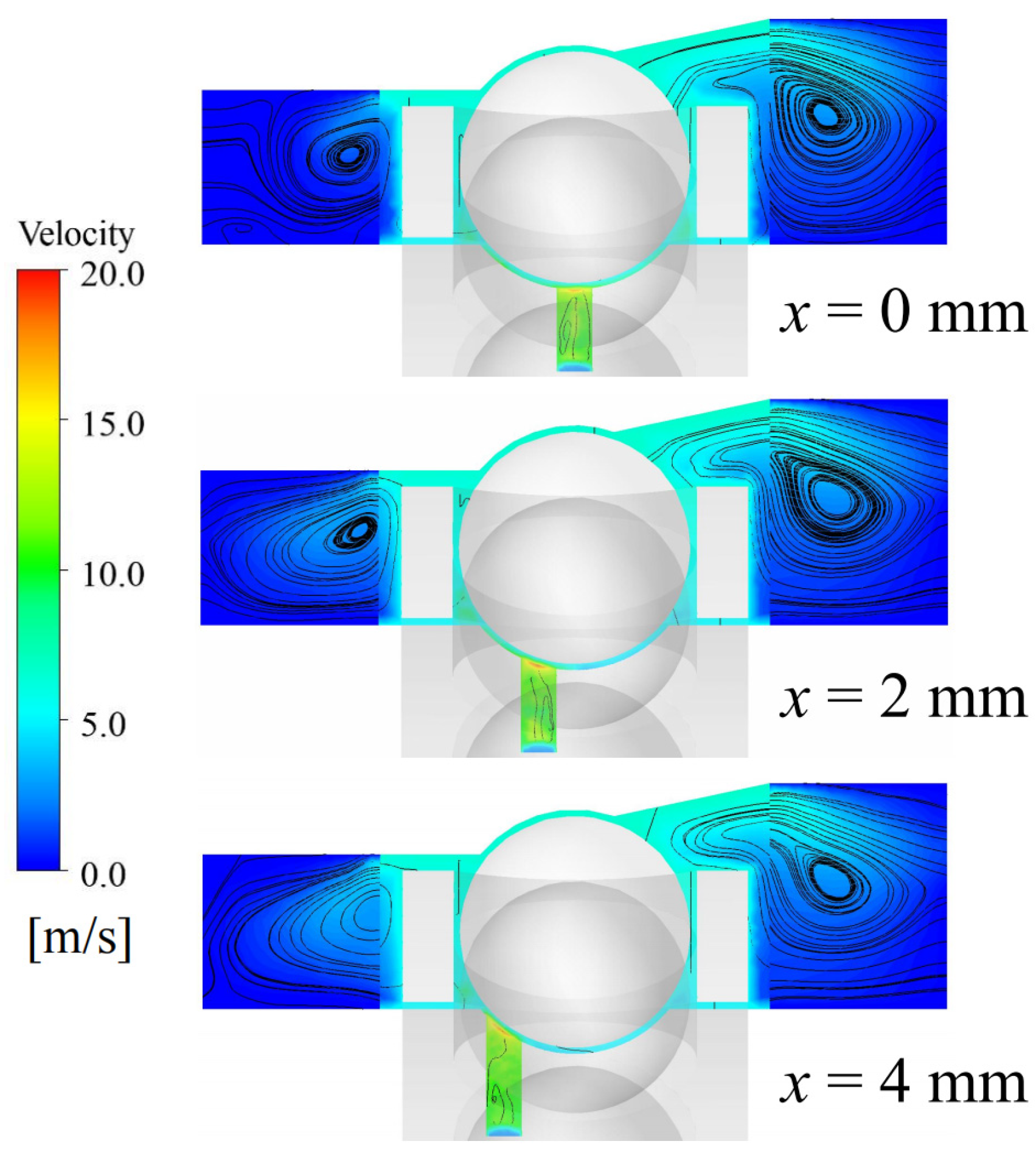
The flow-field results in Figure 16 explain this behavior. When x = 0 mm, the lubricant enters the bearing cavity near the mid-plane, and the streamline distribution on both sides of the rolling element remains relatively stable. Although local vortices exist near both end regions, the flow field still allows a large fraction of the oil to be transported toward the large-clearance end, which can be attributed to the less restricted axial discharge path on that side. When the inlet holes are shifted toward the small-clearance end, the inlet jet and the high-velocity region move closer to the small-clearance side, and the streamline distribution around the rolling element becomes more asymmetric. Part of the oil is then more likely to be entrained into the local vortex or directed toward the small-clearance outlet region, reducing the fraction discharged from the large-clearance end.
Figure 16.
Effect of axial position of oil inlet holes on velocity and streamline distributions in the bearing cavity at n = 3000 rpm and Q = 105 L/h.
At x = 4 mm, the inlet jet is closest to the small-clearance end, and the local disturbance near the inlet and rolling element becomes more evident. The axial transport path toward the large-clearance end is weakened, while the oil–air mixture is more easily redistributed within the cavity or directed toward the small-clearance end. This explains the significant decrease in the oil return ratio at the large-clearance end. Combined with the lubrication results in Figure 10, the offset inlet position can enhance local cage wetting, but it is unfavorable for maintaining a high oil return ratio at the large-clearance end. Therefore, from the viewpoint of large-clearance-end oil return, arranging the inlet holes near the bearing mid-plane is more favorable.
4.2.3. Effects of Oil Inlet Hole Diameter
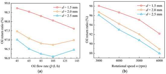
Figure 17 shows the effect of oil inlet hole diameter on the oil return ratio at the large-clearance end. The inlet hole diameter affects the injection velocity and jet penetration, thereby influencing the subsequent oil transport and discharge behavior.
Figure 17.
Effect of oil inlet hole diameter on the oil return ratio at the large-clearance end: (a) variation with oil flow rate at n = 3000 rpm; (b) variation with rotational speed at Q = 105 L/h.
As shown in Figure 17a, the oil return ratio remains relatively high for all inlet hole diameters, but a clear difference can still be observed. Within the investigated diameter range, d = 1.5 mm gives the highest oil return ratio, followed by d = 2.0 mm and d = 2.5 mm. With increasing oil flow rate, the oil return ratio generally decreases slightly. For d = 1.5 mm, the oil return ratio decreases from about 98.7% at 45 L/h to about 97.6% at 140 L/h. For larger inlet hole diameters, the oil return ratio is lower and follows a similar decreasing tendency.
This trend can be explained by the injection characteristics of the supplied oil. Under the same inlet flow rate, a smaller inlet hole diameter produces a higher injection velocity, which enhances jet penetration and promotes more directional oil transport inside the bearing cavity. This helps the lubricant enter the main flow path and be discharged through the large-clearance end. In contrast, a larger inlet hole diameter reduces the injection velocity and weakens the jet penetration ability. The supplied oil is more likely to disperse in the bearing cavity, participate in local circulation, or be redistributed toward other regions, thereby reducing the fraction discharged from the large-clearance end.
Figure 17b shows that increasing rotational speed decreases the oil return ratio for all inlet hole diameters. At Q = 105 L/h, the oil return ratio at d = 1.5 mm decreases from about 98% at 3000 rpm to approximately 92% at 6000 rpm. For d = 2.5 mm, it decreases from about 96% to about 88% over the same speed range. This indicates that high-speed rotation weakens the relative discharge through the large-clearance end, and the effect becomes more evident when the inlet hole diameter is larger. A smaller inlet hole diameter can partly mitigate this effect by maintaining stronger jet penetration and a more concentrated oil supply direction.
Within the investigated diameter range, reducing the inlet hole diameter is beneficial for both rolling-element lubrication and large-clearance-end oil return. As shown in the lubrication performance analysis, a smaller inlet hole diameter improves the oil volume fraction on the rolling element surfaces. The present results further indicate that it also helps maintain a higher oil return ratio at the large-clearance end. Therefore, the inlet hole diameter should be selected to ensure sufficient jet penetration, effective rolling-element lubrication, and favorable oil discharge through the large-clearance end.
4.2.4. Effects of Number of Oil Inlet Holes
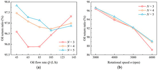
Figure 18 shows the effect of the number of oil inlet holes on the oil return ratio at the large-clearance end. Compared with the axial position and diameter of the inlet holes, the number of inlet holes has a relatively limited influence on the oil return ratio, but it still affects the stability and circumferential uniformity of oil discharge.
Figure 18.
Effect of the number of oil inlet holes on the oil return ratio at the large-clearance end: (a) variation with oil flow rate at n = 3000 rpm; (b) variation with rotational speed at Q = 105 L/h.
As shown in Figure 18a, the oil return ratio remains at a high level for all inlet-hole numbers, ranging approximately from 96% to 98%. In most cases, N = 5 gives a slightly higher oil return ratio than N = 3 and N = 4, indicating that more inlet holes can improve the circumferential uniformity of oil supply and facilitate a more stable discharge through the large-clearance end. However, the variation with oil flow rate is not strictly monotonic, especially when N = 3. In this case, the oil return ratio first decreases and then increases with increasing oil flow rate, suggesting that when the number of inlet holes is small, the injected oil is more locally concentrated and the discharge behavior becomes more sensitive to the interaction among the oil jet, rotating components, and internal vortex structures.
For N = 4 and N = 5, the oil return ratio varies more smoothly with oil flow rate. This indicates that increasing the number of inlet holes can reduce local injection concentration and improve the stability of oil discharge. However, the improvement remains limited because the outlet distribution is also controlled by the rotating flow field and axial clearance difference.
The rotational-speed effect in Figure 18b is more pronounced than the effect of inlet-hole number. At Q = 105 L/h, the oil return ratios for different inlet-hole numbers are close at 3000 rpm and are all higher than 96%. When the rotational speed increases to 6000 rpm, the oil return ratio decreases to about 87–89%. Although N = 5 still maintains a slightly higher oil return ratio than the other cases at most speeds, its advantage becomes limited under high-speed conditions because the internal flow field is mainly governed by strong shear-driven airflow and centrifugal transport.
Increasing the number of inlet holes is generally beneficial for improving circumferential oil supply uniformity and maintaining a relatively high oil return ratio at the large-clearance end. However, its influence on oil return performance is weaker than that of inlet-hole axial position and rotational speed. Therefore, the number of inlet holes should be optimized together with other inlet parameters rather than considered independently.
4.3. Relationship Between Oil–Air Two-Phase Flow Distribution and Oil Return Characteristics
The oil return behavior at the bearing ends is closely related to the redistribution of lubricant after it enters the bearing cavity. The supplied oil can be temporarily retained on the rolling element and cage surfaces, participate in recirculating flow inside the cavity, or be transported toward the two axial outlets. Therefore, the average oil volume fraction on the bearing component surfaces and the oil return ratio at the large-clearance end represent two different outcomes of the same internal oil redistribution process. The former reflects local surface oil retention, whereas the latter characterizes the relative proportion of the supplied oil discharged through the large-clearance end. Consequently, a higher surface oil volume fraction does not necessarily correspond to a higher oil return ratio.
This relationship is clearly reflected in the effects of oil flow rate and rotational speed. Increasing the oil flow rate increases the average oil volume fraction on the rolling element and cage surfaces, indicating greater surface oil retention. However, the oil return ratio at the large-clearance end decreases slightly. This suggests that the additional supplied oil is partly retained or redistributed within the bearing cavity and toward the small-clearance end rather than being proportionally discharged through the large-clearance outlet. In contrast, increasing rotational speed decreases both the surface oil volume fraction and the large-clearance-end oil return ratio. Stronger centrifugal transport and shear-driven airflow remove lubricant from the component surfaces while simultaneously intensifying circumferential and axial redistribution, thereby reducing the fraction of oil following the preferential discharge path toward the large-clearance end.
The effect of inlet-hole axial position provides further evidence of this redistribution mechanism. When the inlet holes are shifted toward the small-clearance end, the average oil volume fraction on the rolling element surfaces decreases, while that on the cage surface increases. At the same time, the oil return ratio at the large-clearance end decreases markedly. This indicates that the inlet offset redirects lubricant toward the cage and small-clearance-side region, changing both the local surface oil distribution and the axial outlet allocation. In contrast, a smaller inlet-hole diameter produces stronger jet penetration and more directional lubricant transport, resulting in both a higher oil volume fraction on the rolling element surfaces and a relatively higher oil return ratio at the large-clearance end.
These results demonstrate that the relationship between internal oil distribution and end oil return is pathway-dependent rather than simply proportional. Surface oil retention and large-clearance-end oil return are controlled by how the supplied lubricant is redistributed among component surfaces, internal recirculation regions, and the two axial outlets. Therefore, changes in operating conditions or inlet-hole configuration may produce either the same or opposite trends in surface oil volume fraction and oil return ratio, depending on how the internal lubricant transport path is altered.
5. Conclusions
In this study, an oil–air two-phase flow model of an angular contact ball bearing with under-race lubrication was established using the VOF method. An under-race lubrication test rig was constructed to validate the numerical model. The effects of oil flow rate, rotational speed, axial position of oil inlet holes, inlet hole diameter, and number of inlet holes on lubrication performance and oil return characteristics were investigated. The main conclusions are as follows:
- (1)
- The numerical results agree well with the experimental measurements. Under the oil flow rate of 105 L/h, both the simulated and experimental oil return ratios at the large-clearance end decrease with increasing rotational speed. The maximum relative error between simulation and experiment is 3.17%, indicating that the numerical model can reasonably predict the oil flow allocation behavior of the bearing.
- (2)
- Increasing the oil flow rate improves the oil supply level inside the bearing and increases the oil volume fraction on the rolling element and cage surfaces. However, this improvement becomes less pronounced at high flow rates. In contrast, increasing the rotational speed significantly reduces the oil volume fraction on both surfaces because the enhanced centrifugal transport and shear-driven airflow accelerate oil removal and redistribution inside the bearing cavity. The rolling element surfaces retain more lubricant than the cage surface, while the cage surface is more sensitive to secondary oil flow, splash, and local redistribution.
- (3)
- The oil inlet structure has a significant influence on lubricant distribution. Shifting the inlet holes toward the small-clearance end promotes local oil enrichment and cage wetting, but it decreases the average oil volume fraction on the rolling element surfaces. Within the investigated range, a smaller inlet hole diameter improves the oil supply to the rolling elements by increasing jet penetration, while increasing the number of inlet holes enhances the circumferential uniformity of oil supply. The inlet hole diameter mainly affects jet penetration, whereas the number of inlet holes mainly affects circumferential oil distribution.
- (4)
- The large-clearance end is the dominant oil discharge side in the present bearing configuration, but the oil return ratio at this end decreases with increasing oil flow rate and rotational speed. The reduction is caused by intensified oil–air mixing, vortex motion, and internal redistribution, which disturb the preferential discharge path toward the large-clearance outlet. The axial position of the inlet holes affects the outlet flow allocation: shifting the inlet holes toward the small-clearance end markedly reduces the oil return ratio at the large-clearance end. Within the investigated range, arranging the inlet holes near the bearing mid-plane, using a smaller inlet hole diameter, and increasing the number of inlet holes are more favorable for balancing rolling-element lubrication and large-clearance-end oil return.
Author Contributions
Conceptualization, C.Y. and Y.D.; methodology, J.Z., R.T. and J.L.; software, J.Z., R.T. and J.L.; validation, J.Z., R.T. and C.Y.; formal analysis, J.L.; investigation, J.Z., R.T. and C.Y.; resources, C.Y. and Y.D.; data curation, J.Z., R.T. and J.L.; writing—original draft preparation, J.Z. and R.T.; writing—review and editing, C.Y. and Y.D.; visualization, J.L. and Y.D.; supervision, C.Y. and Y.D.; project administration, Y.D.; funding acquisition, Y.D. All authors have read and agreed to the published version of the manuscript.
Funding
This work was supported by the National Natural Science Foundation of China (Grant Nos. 52305081 and 52475078), the Hunan Provincial Natural Science Foundation of China (Grant No. 2026JJ60427), the Science and Technology Innovation Program of Hunan Province (Grant No. 2024RC1001), and the Stable Support Project (Grant Nos. XX01073 and CXPT-2022-015).
Data Availability Statement
The original contributions presented in the study are included in the article; further inquiries can be directed to the corresponding author.
Acknowledgments
We are grateful to the High Performance Computing Center of Central South University for assistance with the computations.
Conflicts of Interest
Authors Jianfeng Zhong and Juan Liu were employed by the company Hunan Aviation Powerplant Research Institute, Aero Engine Corporation of China. The remaining authors declare that the research was conducted in the absence of any commercial or financial relationships that could be construed as a potential conflict of interest.
References
- Grujičić, R.; Tica, M.; Stojanović, B.; Ivanović, L.; Mitrović, R.; Tomović, R. Analysis of impact of shaft speed and external load on the radial ball bearing lubrication regimes. FME Trans. 2022, 50, 109–120. [Google Scholar] [CrossRef] [Scilit]
- Sun, J.; Wu, Y.; Yang, J.; Yao, J.; Xia, Z.; Ma, T.; Luo, J. Friction properties and distribution rule of lubricant film of full ceramic ball bearing under different service condition. J. Ceram.-Silik. 2022, 66, 54–65. [Google Scholar] [CrossRef] [Scilit]
- Jiang, S.; Mao, H. Investigation of the high speed rolling bearing temperature rise with oil-air lubrication. J. Tribol. 2011, 133, 021101. [Google Scholar] [CrossRef] [Scilit]
- Zheng, D.X.; Zheng, D. An efficient thermal model for high-speed angular contact ball bearings based on oil-air two-phase flow and gray-box model. Ind. Lubr. Tribol. 2023, 75, 1199–1207. [Google Scholar] [CrossRef] [Scilit]
- Gao, M.; Liang, H.; Wang, W.; Chen, H. Oil redistribution and replenishment on stationary bearing inner raceway. Tribol. Int. 2022, 165, 107315. [Google Scholar] [CrossRef] [Scilit]
- Liang, H.; Zhang, Y.; Wang, W. Influence of the cage on the migration and distribution of lubricating oil inside a ball bearing. Friction 2022, 10, 1035–1045. [Google Scholar] [CrossRef] [Scilit]
- Chen, H.; Wang, W.; Liang, H.; Ge, X. Observation of the oil flow in a ball bearing with a novel experiment method and simulation. Tribol. Int. 2022, 174, 107731. [Google Scholar] [CrossRef] [Scilit]
- Tohyama, M.; Ohmiya, Y.; Hirose, M.; Matsuyama, H.; Toda, T.; Hasegawa, K.; Onizuka, T.; Sato, H.; Yokoi, M.; Sato, N. Visualization of oil-lubrication ball bearings at high rotational speeds. Front. Mech. Eng. 2024, 10, 1416656. [Google Scholar] [CrossRef] [Scilit]
- Hu, J.; Wu, W.; Wu, M.; Yuan, S. Numerical investigation of the air-oil two-phase flow inside an oil-jet lubricated ball bearing. Int. J. Heat Mass Transf. 2014, 68, 85–93. [Google Scholar] [CrossRef] [Scilit]
- Wu, W.; Hu, C.; Hu, J.; Yuan, S. Jet cooling for rolling bearings: Flow visualization and temperature distribution. Appl. Therm. Eng. 2016, 105, 217–224. [Google Scholar] [CrossRef] [Scilit]
- Wu, W.; Hu, J.; Yuan, S.; Hu, C. Numerical and experimental investigation of the stratified air-oil flow inside ball bearings. Int. J. Heat Mass Transf. 2016, 103, 619–626. [Google Scholar] [CrossRef] [Scilit]
- Yan, K.; Zhang, J.; Hong, J.; Wang, Y.; Zhu, Y. Structural optimization of lubrication device for high speed angular contact ball bearing based on internal fluid flow analysis. Int. J. Heat Mass Transf. 2016, 95, 540–550. [Google Scholar] [CrossRef] [Scilit]
- Liu, J.; Ni, H.; Xu, Z.; Pan, G. A simulation analysis for lubricating characteristics of an oil-jet lubricated ball bearing. Simul. Model. Pract. Theory 2021, 113, 102371. [Google Scholar] [CrossRef] [Scilit]
- Deng, S.; Zhao, G.; Qian, D.; Jiang, S.; Hua, L. Investigation of oil-air flow and temperature for high-speed ball bearings by combining nonlinear dynamic and computational fluid dynamics models. J. Tribol. 2022, 144, 071204. [Google Scholar] [CrossRef] [Scilit]
- Bao, H.; Hou, X.; Lu, F. Analysis of oil-air two-phase flow characteristics inside a ball bearing with under-race lubrication. Processes 2020, 8, 1223. [Google Scholar] [CrossRef] [Scilit]
- Bao, H.; Hou, X.; Tang, X.; Lu, F. Analysis of temperature field and convection heat transfer of oil-air two-phase flow for ball bearing with under-race lubrication. Ind. Lubr. Tribol. 2021, 73, 817–821. [Google Scholar] [CrossRef] [Scilit]
- Yu, Q.; Gao, W.; Gong, P.; Li, Y.; Li, C. Oil distribution around ball-raceway local contact region in under-race lubrication of ball bearing. Dynamics 2024, 4, 731–746. [Google Scholar] [CrossRef] [Scilit]
- Lyu, Y.; Li, Y.; Li, C.; Jiang, L.; Liu, Z. Oil-air distribution prediction inside ball bearing with under-race lubrication based on numerical simulation. Appl. Sci. 2024, 14, 3770. [Google Scholar] [CrossRef] [Scilit]
- Gong, P.; Liu, Z.; Yu, Q.; Chen, F. Research on internal two-phase flow in the local micro-clearance design of a high-speed ball bearing with under-race lubrication. Lubr. Sci. 2024, 36, 216–230. [Google Scholar] [CrossRef] [Scilit]
- Niu, R.; Wang, G.; Zhang, Y.; Zhang, K.; Lin, B. Analysis of under-race lubrication oil supply effects on high-speed split inner ring angular contact ball bearings based on fluid-thermal-structural coupling. Prog. Eng. Sci. 2026, 3, 100246. [Google Scholar] [CrossRef] [Scilit]
- Hu, X.; Lin, J. Study on flow field characteristics of high-speed double-row ball bearings with under-race lubrication. Aerospace 2025, 12, 861. [Google Scholar] [CrossRef] [Scilit]
- Adeniyi, A.A.; Morvan, H.; Simmons, K. A computational fluid dynamics simulation of oil-air flow between the cage and inner race of an aero-engine bearing. J. Eng. Gas. Turbines Power 2017, 139, 012506. [Google Scholar] [CrossRef] [Scilit]
- Liu, H.; Li, Y.; Liu, G. Numerical investigation of oil spray lubrication for transonic bearings. J. Braz. Soc. Mech. Sci. Eng. 2018, 40, 401. [Google Scholar] [CrossRef] [Scilit]
- Hu, J.; Xun, B.; Zhang, X.M.; Zhang, Q.Y.; Li, G.W. Design and research of new-type nozzle structure based on oil-air lubrication. Meccanica 2024, 59, 1–18. [Google Scholar] [CrossRef] [Scilit]
- Wei, C.; Wu, W.; Hou, X.; Nelias, D.; Yuan, S. Research on mechanism of enhancing lubrication flow field regulation of high-speed bearing functional cage. Tribol. Int. 2023, 188, 108780. [Google Scholar] [CrossRef] [Scilit]
- Qian, S.; Wang, B.; Du, X.; Chen, X. Lubrication enhancement of high-speed angular contact ball bearings by adding diversion hole in cage. J. Braz. Soc. Mech. Sci. Eng. 2025, 47, 164. [Google Scholar] [CrossRef] [Scilit]
- Zi, X.; Chen, K.; Bai, Q.; Li, X.; Jin, X.; Wang, X.; Guo, F. The enhancement of oil delivery and bearing performance via a guiding-structured nozzle under oil-air lubrication. Lubricants 2024, 12, 60. [Google Scholar] [CrossRef] [Scilit]
- Wen, B.; Li, Y.; Wang, M.; Yang, Y. Measurement for lubricant distribution in an angular contact ball bearing and its influence investigation. Lubricants 2023, 11, 63. [Google Scholar] [CrossRef] [Scilit]
- Arya, U.; Sadeghi, F.; Aamer, S.; Meinel, A.; Grillenberger, H. In situ visualization and analysis of oil starvation in ball bearing cages. Tribol. Trans. 2023, 66, 965–978. [Google Scholar] [CrossRef] [Scilit]
- Jin, X.; Li, X.; Liu, Y.; Gao, J.; Bai, L. Experimental study of lubricant distribution and lubrication enhancement induced by ball bearing cage. J. Tribol. 2024, 146, 074103. [Google Scholar] [CrossRef] [Scilit]
- Dai, Y.; Tang, R.; Yu, C.; Yang, C.; Yang, D.; Zhu, X. Air–oil two-phase flow and oil penetration characteristics of angular contact ball bearing under oil jet lubrication: Numerical and experimental investigations. Phys. Fluids 2025, 37, 047133. [Google Scholar] [CrossRef] [Scilit]

Disclaimer/Publisher’s Note: The statements, opinions and data contained in all publications are solely those of the individual author(s) and contributor(s) and not of MDPI and/or the editor(s). MDPI and/or the editor(s) disclaim responsibility for any injury to people or property resulting from any ideas, methods, instructions or products referred to in the content. |
© 2026 by the authors. Licensee MDPI, Basel, Switzerland. This article is an open access article distributed under the terms and conditions of the Creative Commons Attribution (CC BY) license.