


Abstract
To mitigate the deterioration of the tribological performance of end-face friction pairs under low-speed conditions, this study investigated a water-lubricated CF/PEEK–316L stainless steel end-face friction pair. Surface micro-textures with different depth-to-diameter ratios and texture area ratios were fabricated on the 316L stainless steel surface to evaluate the effects of texture parameters and sliding speed on tribological performance. The results showed that appropriately designed micro-textures effectively reduced the coefficient of friction and improved the wear characteristics of the friction pair. Among the tested conditions, the CF/PEEK–316L stainless-steel tribo-pair with a 316L counterface textured at ε = 0.05 and s = 10% exhibited the lowest average friction coefficient. At 200 rpm, this textured tribo-pair exhibited an average friction coefficient approximately 34.8% lower than that of the untextured tribo-pair. Furthermore, laser micro-textures suppressed interfacial material transfer and mitigated adhesive wear and three-body abrasive wear by capturing wear debris. Gear-pump prototype tests further showed that the textured surface improved flow-delivery and volumetric-efficiency performance, while promoting more uniform end-face wear morphology, indicating its potential application in practical gear-pump components. The findings provide guidance for surface-texture design and tribological-performance optimization of polymer/metal end-face friction pairs.
1. Introduction
End-face friction pairs are widely applied in hydraulic components, pumps, and sealing systems, and their tribological behavior directly affects the operating efficiency, stability, and service life of mechanical systems [1,2]. Under transient operating conditions, such as start–stop processes, low-speed regulation, and load fluctuations, end-face friction pairs are susceptible to lubrication degradation and local contact, leading to increased friction and surface damage [3]. As a typical application of end-face friction pairs, gear pumps are highly affected by the friction and wear behavior at the interface between the pump body and gear end faces, which plays a critical role in determining volumetric efficiency and operational reliability [4]. Therefore, reducing interfacial friction and mitigating surface damage are essential for improving the performance of gear pumps.
Engineering polymers, particularly polyetheretherketone (PEEK) and its composites, have attracted increasing attention for gear pumps and other engineering applications because of their low density, low vibration and noise, favorable tribological and self-lubricating properties, excellent chemical resistance, and high specific strength [5,6,7]. For example, miniature gear pairs made of PEEK were fabricated and applied in gear pumps [8]. In practical engineering applications, PEEK and its composites are often paired with metallic materials, such as stainless steel, to achieve a balance between load-bearing capacity and interfacial tribological performance [9]. However, during long-term sliding contact, adhesive wear, material transfer, and abrasive wear may still occur between PEEK composites and metallic counterfaces, thereby compromising tribological performance and causing surface damage [9,10].
Currently, the tribological performance of end-face friction pairs can be improved through material modification, surface coatings, lubrication regulation, and surface micro-texturing [11,12]. Among these approaches, surface micro-texturing has attracted considerable attention because of its ability to improve the tribological performance of mechanical components under different lubrication conditions while offering high efficiency, cost-effectiveness, and environmental friendliness [13]. Among the available fabrication techniques, laser processing is the most widely used owing to its high precision, high processing efficiency, and relatively low cost [14,15]. The tribological performance of micro-textured surfaces depends on texture dimensions, shape, arrangement, and operating conditions. Properly designed textures can regulate interfacial contact, retain lubricant, and trap wear debris [16,17,18]. Although their relative effects vary with the material pair and operating conditions, the depth-to-diameter ratio and texture area ratio are commonly selected as key design variables [19]. Yan et al. [20] varied dimple diameters of 50–300 μm, depths of 5–20 μm, and area ratios of 5–20%; under their test conditions, diameters of 100–200 μm and depths of 5–10 μm gave favorable friction reduction, with the area ratio being the most influential parameter. Schneider et al. [21] reported the lowest friction at a depth-to-diameter ratio of 0.10 and an area ratio of 10% under mixed lubrication. Mo et al. [22] summarized five circular-dimple studies with area ratios of 5–13% and depth-to-diameter ratios mostly between 0.067 and 0.10. Niu et al. [23,24] investigated circular dimples under starved lubrication and reported favorable performance at a diameter of 100 μm, a depth of 10 μm, and an area ratio of 10%; their tested area-ratio range included 5–20%. Xue et al. [25] examined texture area ratios of 5–20% and reported favorable performance for a 15% elliptical texture with an aspect ratio of 0.1. These studies support the present parameter ranges as representative values, while the optimum texture dimensions remain dependent on the material pair and operating conditions.
Previous studies on PEEK-based materials sliding against stainless steel have primarily focused on material reinforcement, friction and wear behavior under lubricated conditions, and interfacial damage mechanisms. Carbon-fiber reinforcement has been shown to improve the load-bearing capacity and wear resistance of PEEK composites, whereas lubrication conditions, sliding speed, and applied load can affect transfer-film formation and wear evolution [26,27,28,29]. In recent years, surface texturing has been increasingly applied to metallic counterfaces to improve the tribological performance of CF/PEEK friction pairs. Its effectiveness is governed by texture geometry, dimensions, arrangement, material pair, and operating conditions. Under aqueous lubrication, suitably designed textures can regulate interfacial contact, retain lubricant, and trap wear debris, thereby mitigating abrasive interactions [30,31,32,33,34]. However, most previous studies have focused on texture shape and bioinspired structural design. The combined effects of key geometric parameters, such as depth-to-diameter ratio and texture area ratio, the wear evolution mechanisms under low-speed end-face sliding, and the performance of textured surfaces in actual gear pumps remain insufficiently understood.
To address these gaps, this study investigated a water-lubricated CF/PEEK–316L stainless-steel end-face tribo-pair. Micro-dimples with different depth-to-diameter ratios and texture area ratios were fabricated on the 316L stainless-steel surface to examine the effects of texture parameters and rotational speed on friction behavior and end-face wear characteristics. Three-dimensional surface characterization, SEM, and EDS were used to analyze the associated wear and material-transfer mechanisms. Comparative gear-pump prototype tests were further conducted to assess the effects of the textured pump-body surface on output flow rate, volumetric efficiency, and end-face wear characteristics.
2. Materials and Methods
2.1. Materials and Specimen Preparation
To represent the intended gear-pump material contact, 316L stainless steel and CF/PEEK were selected as the lower and upper specimens to simulate the pump body and gear, respectively [35]. The mechanical properties and chemical composition of 316L stainless steel are listed in Table 1 and Table 2, respectively. The CF/PEEK material used in this study was VICTREX™ PEEK 450CA30 produced by Victrex plc, UK, containing 30 wt.% carbon fiber. The initial surface roughness of the specimen was approximately Ra 1.2 μm, and its main properties are listed in Table 3. Because gear pumps can be used to convey low-viscosity fluids and water can serve as the working medium in certain applications [36,37], purified water was selected as the lubricating medium. This study focuses on the fundamental tribological behavior of the CF/PEEK–316L stainless-steel tribo-pair under low-viscosity water-lubricated conditions.
Table 1.
Mechanical properties of 316L stainless steel.
Table 2.
Chemical composition of 316L stainless steel.
Table 3.
Properties of CF/PEEK.
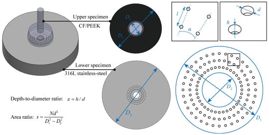
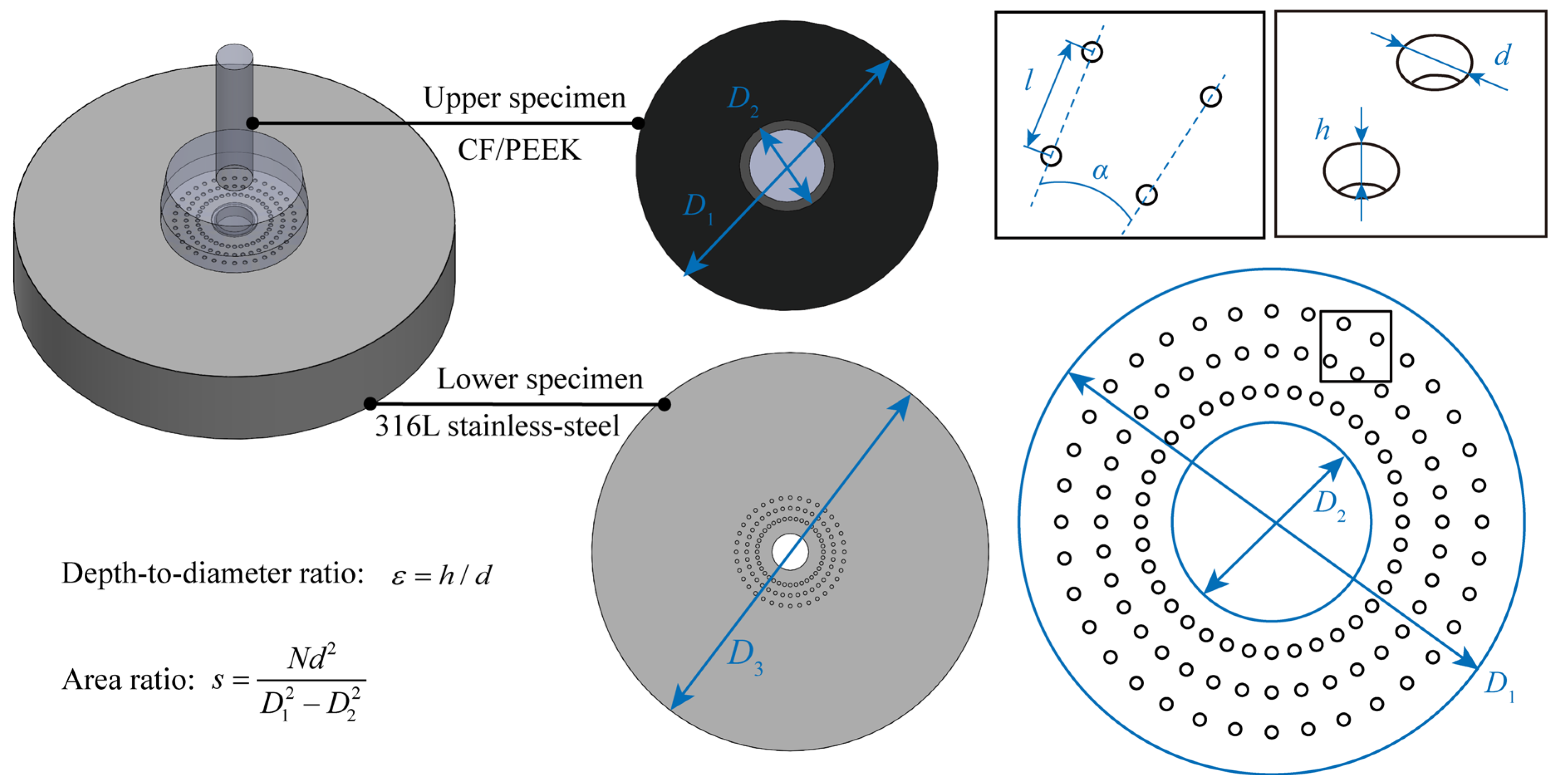
Regularly arranged circular textures were adopted to minimize the additional effects associated with texture shape and directional orientation. The texture diameter was fixed at 100 μm to isolate the effects of dimple depth and texture area ratio. The selected depth-to-diameter ratios were 0.05, 0.10, and 0.15, and the texture area ratios were 5%, 10%, and 20%. These values encompass representative parameter ranges reported in previous studies [20,21,22,23,24,25] and were selected for this preliminary parametric investigation; they should not be regarded as optimum values for the present water-lubricated tribo-pair. Figure 1 presents the 3D model of the tribo-pair, the geometric parameters of the surface textures, and the equations used to calculate the texture depth-to-diameter ratio and area ratio. Here, l denotes the radial spacing between the textures; α denotes the angular spacing between adjacent textures; h and d denote the depth and diameter of the micro-dimples, respectively; N denotes the number of micro-dimples; where D1 and D2 denote the outer and inner diameters of the CF/PEEK specimen, respectively, with D1 = 12.7 mm and D2 = 5 mm. The detailed texture parameters are listed in Table 4.
Figure 1.
3D model of the tribo-pair, geometric parameters of the surface textures.
Table 4.
Surface texture parameters.
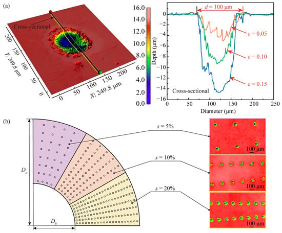
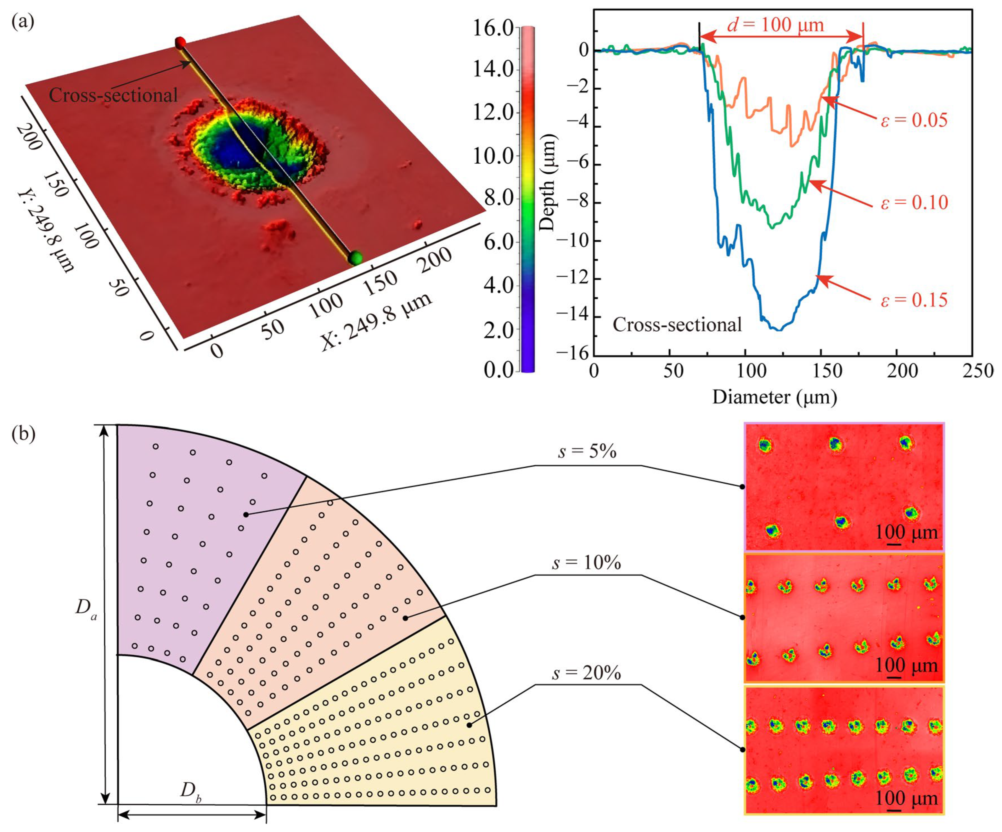
An EM50DS laser marking system (Han’s Laser, Shenzhen, China) was used to fabricate surface micro-textures on the lower specimens, and its main technical specifications are listed in Table 5. Surface micro-textures with different depth-to-diameter ratios were produced by adjusting the scanning speed, laser power, pulse repetition frequency, and number of processing passes, as detailed in Table 6. After laser texturing, the surfaces of the lower specimens were deburred using abrasive paper, and the surface roughness was controlled to Ra ≤ 0.05 μm. The fabricated textures were characterized using a 3D optical profilometer (SuperView W1-Plus, CHOTEST, Shenzhen, China). The 3D morphologies of the micro-textured surfaces with different depth-to-diameter ratios and texture area ratios are shown in Figure 2a,b, respectively.
Table 5.
Main technical specifications of the laser marking system.
Table 6.
Laser processing parameters for the surface micro-textures.
Figure 2.
3D morphologies of the surface micro-textures with different parameters: (a) depth-to-diameter ratios; (b) texture area ratios.
2.2. Friction and Wear Test
Prior to the friction and wear tests, the lower 316L stainless steel specimens were ground, polished, and then laser-textured. After laser processing, the specimen surfaces were deburred using abrasive paper, immersed in 75 vol.% ethanol, ultrasonically cleaned for 20 min, and subsequently dried at room temperature. Before testing, the texture morphology of the lower specimens was examined using an optical microscope. After testing, the worn surfaces were characterized using optical microscopy and scanning electron microscopy (SEM; Apreo 2 S, Thermo Fisher Scientific, Hillsboro, OR, USA), while the elemental composition of the worn regions was analyzed using energy-dispersive X-ray spectroscopy (EDS; Ultim Max 65, Oxford Instruments Nanotechnology Tools Ltd., Abingdon, UK).
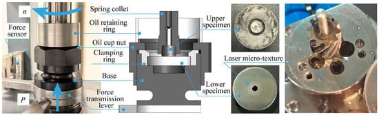
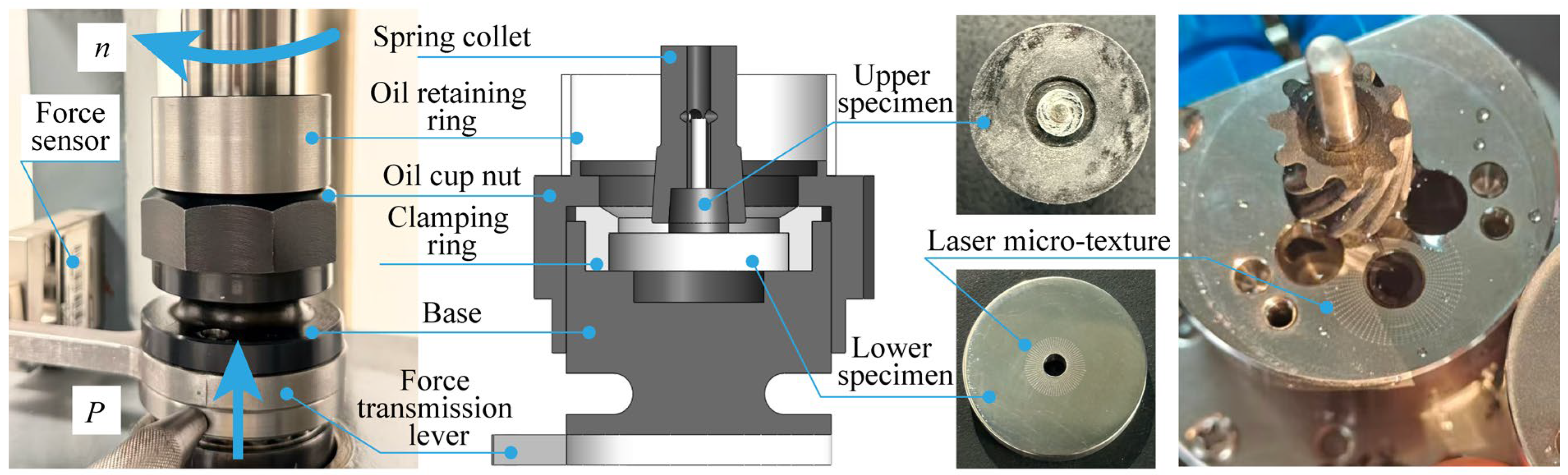
The friction and wear tests were conducted using an MS-10G friction and wear tester (Chenda, Jinan, China), as shown in Figure 3. Before each test, the normal load, test duration, and spindle rotational speed were set according to the experimental scheme. The upper CF/PEEK specimen was secured to the rotating spindle using a conical spring collet and rotated at the prescribed speed, whereas the lower 316L stainless steel disc specimen was fixed to the specimen stage using a clamping ring and remained stationary. During testing, an upward normal load was applied to the lower specimen. The friction torque was continuously measured using the torque sensor integrated into the friction and wear tester and converted into the coefficient of friction by the system software (Version 2018.11.19) supplied with the tester. The complete friction coefficient data were recorded throughout each test, and the average value was calculated automatically after the test. Figure 3 also presents a partial view of the gear-pump prototype, in which the textured region on the pump-body end face is indicated.
Figure 3.
Schematic diagram of the friction and wear testing apparatus and partial view of the gear-pump prototype showing the textured region.
During transient processes, such as start-up, speed regulation, and load fluctuations, gear-pump end-face contacts may experience unfavorable lubrication conditions and increased local contact. The present friction and wear tests were not intended to fully reproduce the complex operating conditions of an actual gear pump, including its contact-pressure distribution and lubricant-circulation environment. Instead, the test conditions were selected to ensure stable operation of the apparatus and to provide a controlled evaluation of the effects of surface micro-textures on the CF/PEEK–316L stainless-steel tribo-pair. The detailed test parameters are listed in Table 7.
Table 7.
Parameters of the friction and wear tests.
A 3D optical profilometer was used to characterize the local surface morphologies, cross-sectional profiles, and surface roughness of the 316L stainless-steel and CF/PEEK specimens before and after the friction and wear tests. These measurements were used to qualitatively assess wear-related surface changes. Because complete pre- and post-test measurements of the entire wear region were difficult to obtain, the available 3D data were insufficient for reliable wear-volume determination; consequently, wear volume and wear rate were not calculated. The worn surfaces were further characterized by SEM and EDS to investigate the wear mechanisms. To assess the engineering applicability of surface micro-texturing, comparative tests were conducted using textured and untextured miniature double-circular-arc line gear pumps under the same operating conditions. The gear geometry, structural design, and axial end-face and radial clearances were consistent with those reported in Ref. [35]. The pump body was made of 316L stainless steel and the gears of PEEK. The theoretical displacement was approximately 0.624 mL/rev. Circular micro-dimples with a diameter of 100 μm, ε = 0.05, and s = 10% were fabricated on the pump-body end face in relative sliding contact with the gear end face. Purified water at room temperature was used as the working fluid, with the pump inlet supplied from an open reservoir at approximately atmospheric pressure. During the rotational-speed tests, the pump outlet was maintained under a near-no-load condition. During the pressure tests, the rotational speed was fixed at 1300 rpm, while the outlet back pressure was increased from 0.05 to 0.35 MPa in increments of 0.05 MPa. After testing, a 3D optical microscope was used to characterize the local surface morphology and cross-sectional profile of the pump-body end face to evaluate wear-related surface changes.
3. Results and Discussion
3.1. Effects of Surface Texture Parameters and Rotational Speed on the Friction Coefficient
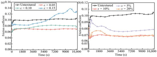
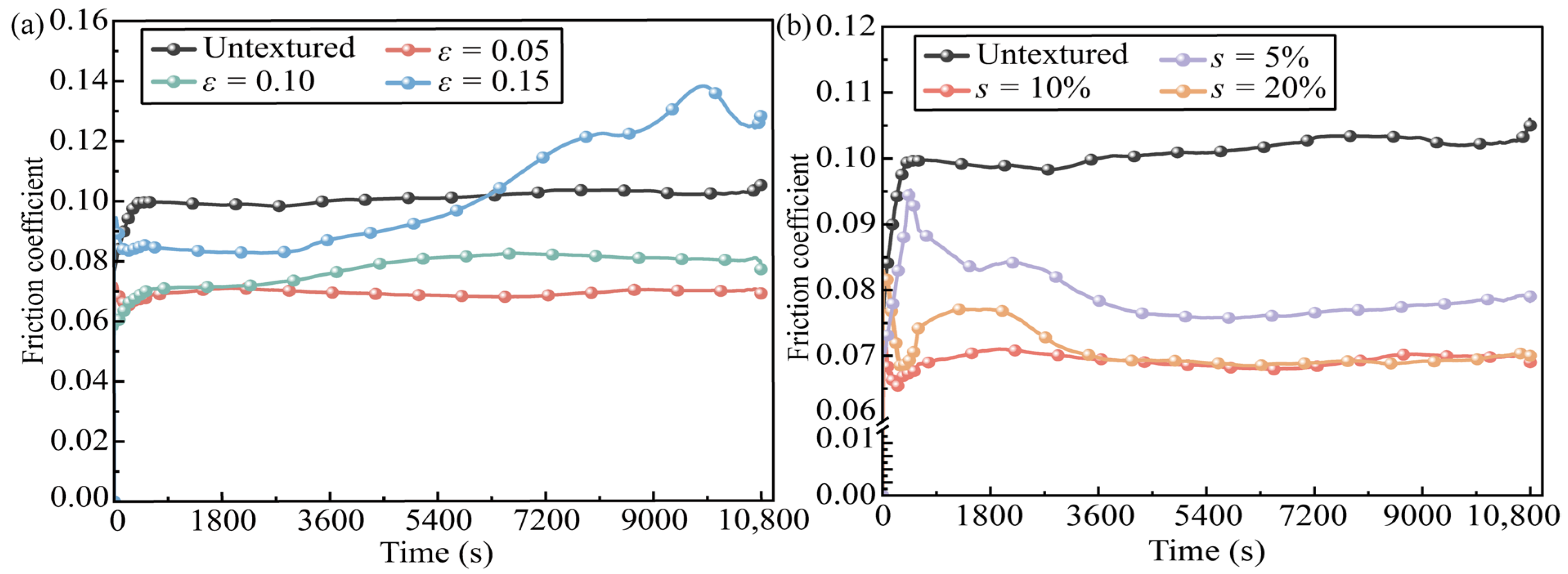
To investigate the effect of texture geometric parameters on the tribological performance of the friction pair, friction and wear tests were conducted under a normal load of 100 N and a rotational speed of 200 rpm. The effects of texture depth-to-diameter ratio (0.05, 0.10, and 0.15, with a fixed texture area ratio of 10%) and texture area ratio (5%, 10%, and 20%, with a fixed depth-to-diameter ratio of 0.05) on the friction behavior were evaluated, as shown in Figure 4a,b, respectively. As shown in Figure 4a, the friction coefficient of the untextured surface remained within the range of 0.098–0.105 and exhibited a slight increasing trend with sliding time. After micro-texturing, the coefficient of friction decreased relative to that of the untextured surface. Among the tested depth-to-diameter ratios, the representative curve for ε = 0.05 exhibited the lowest friction coefficient. As the depth-to-diameter ratio increased, coefficient of friction increased gradually, and its fluctuations became more pronounced. As shown in Figure 4b, the friction coefficient initially decreased and then increased with increasing texture area ratio. All textured surfaces exhibited lower friction coefficient values than the untextured surface. When the texture area ratio was s = 10%, the lowest friction coefficient and the smallest fluctuation were obtained. These results show that suitable combinations of the depth-to-diameter ratio and texture area ratio can reduce friction relative to the untextured surface. The present texture dimensions were selected from representative ranges reported in previous texture-parameter studies [20,21,22,23,24,25], and all textured surfaces exhibited lower friction coefficients than the untextured surface under the present test conditions.
Figure 4.
Effects of texture parameters on the friction coefficient: (a) depth-to-diameter ratio; (b) texture area ratio.
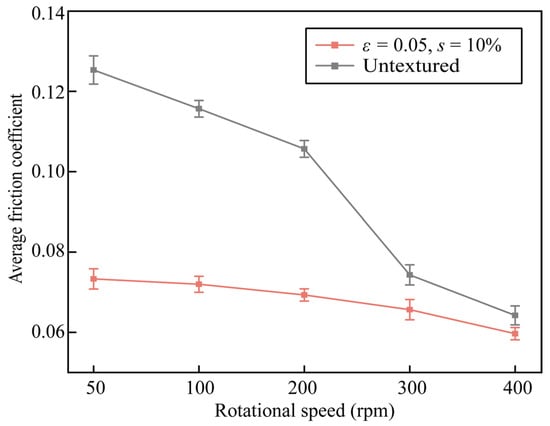
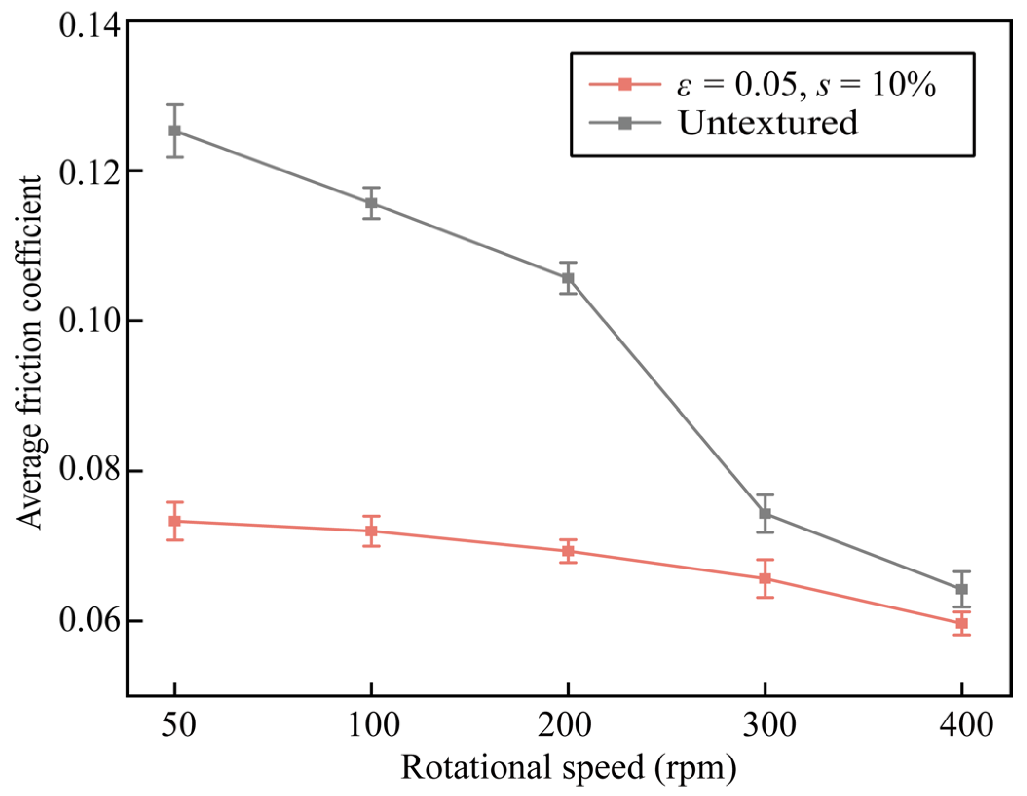
To investigate the effect of rotational speed on the coefficient of friction, comparative tests were conducted on an untextured surface and a micro-textured surface with ε = 0.05 and s = 10%, under a normal load of 100 N. The rotational speed ranged from 50 to 400 rpm, and the results are shown in Figure 5. The results are presented as average values ± standard deviations from three repeated tests. As the rotational speed increased, the average coefficients of friction of both the textured and untextured surfaces decreased. The average coefficient of friction of the untextured surface decreased from approximately 0.12 to 0.068. In comparison, the micro-textured surface exhibited a lower coefficient of friction throughout the entire speed range, with a more pronounced friction-reduction effect at lower rotational speeds. At 200 rpm, the average friction coefficient of the surface with ε = 0.05 and s = 10% was approximately 34.8% lower than that of the untextured surface. Within the present rotational-speed range, the observed decrease in friction coefficient is consistent with the initial decreasing trend reported for textured CF/PEEK–316L tribo-pairs under seawater lubrication [33]. However, because lubricant-film thickness and interfacial temperature were not measured, the underlying lubrication and thermal mechanisms cannot be determined directly from the present data.
Figure 5.
Average coefficient of friction at different rotational speeds.
3.2. Macroscopic Wear Morphology
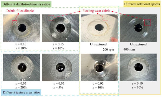
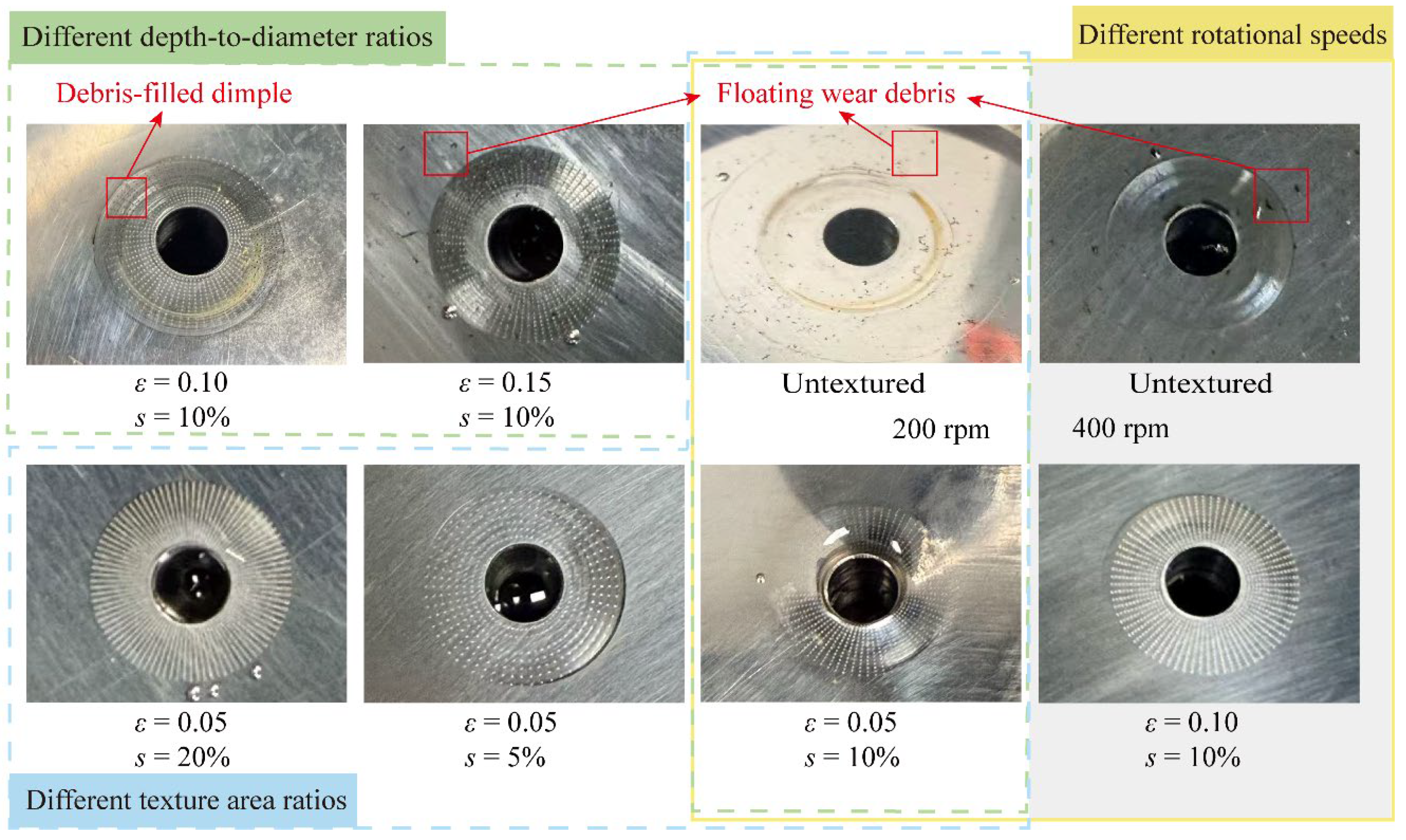
To investigate the effect of texture parameters on the wear behavior of the friction pair, the worn surfaces of the lower 316L stainless steel specimens after the friction and wear tests were examined. Figure 6 shows the macroscopic wear morphologies of the lower specimen surfaces after testing. The untextured surface exhibited obvious wear debris accumulation, with an annular debris accumulation region formed around the edge of the contact area. This indicates that the generated wear debris could not be effectively removed from the contact interface and may subsequently participate in the friction process, leading to aggravated surface damage. In contrast, the accumulation of wear debris was significantly reduced on the textured surfaces. For the surface with ε = 0.05, no obvious debris accumulation was observed, and only slight wear traces appeared. With further increases in the depth-to-diameter ratio, some micro-dimples were gradually filled with wear debris, accompanied by more apparent wear marks. In addition, at each tested rotational speed, the textured surfaces exhibited less pronounced wear-related surface damage than the corresponding untextured surfaces tested at the same speed, suggesting that the micro-textures may alleviate surface damage by retaining wear debris and modifying local contact conditions.
Figure 6.
Macroscopic wear morphologies of the 316L stainless-steel surfaces after friction and wear.
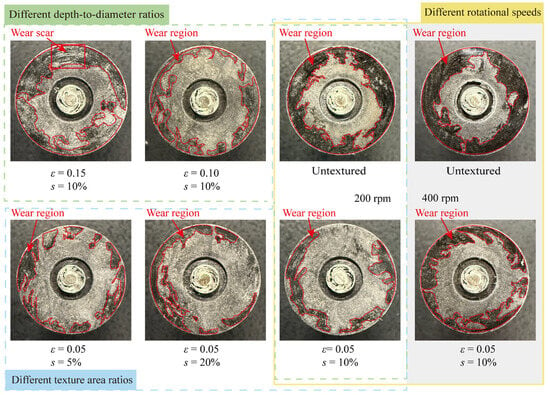
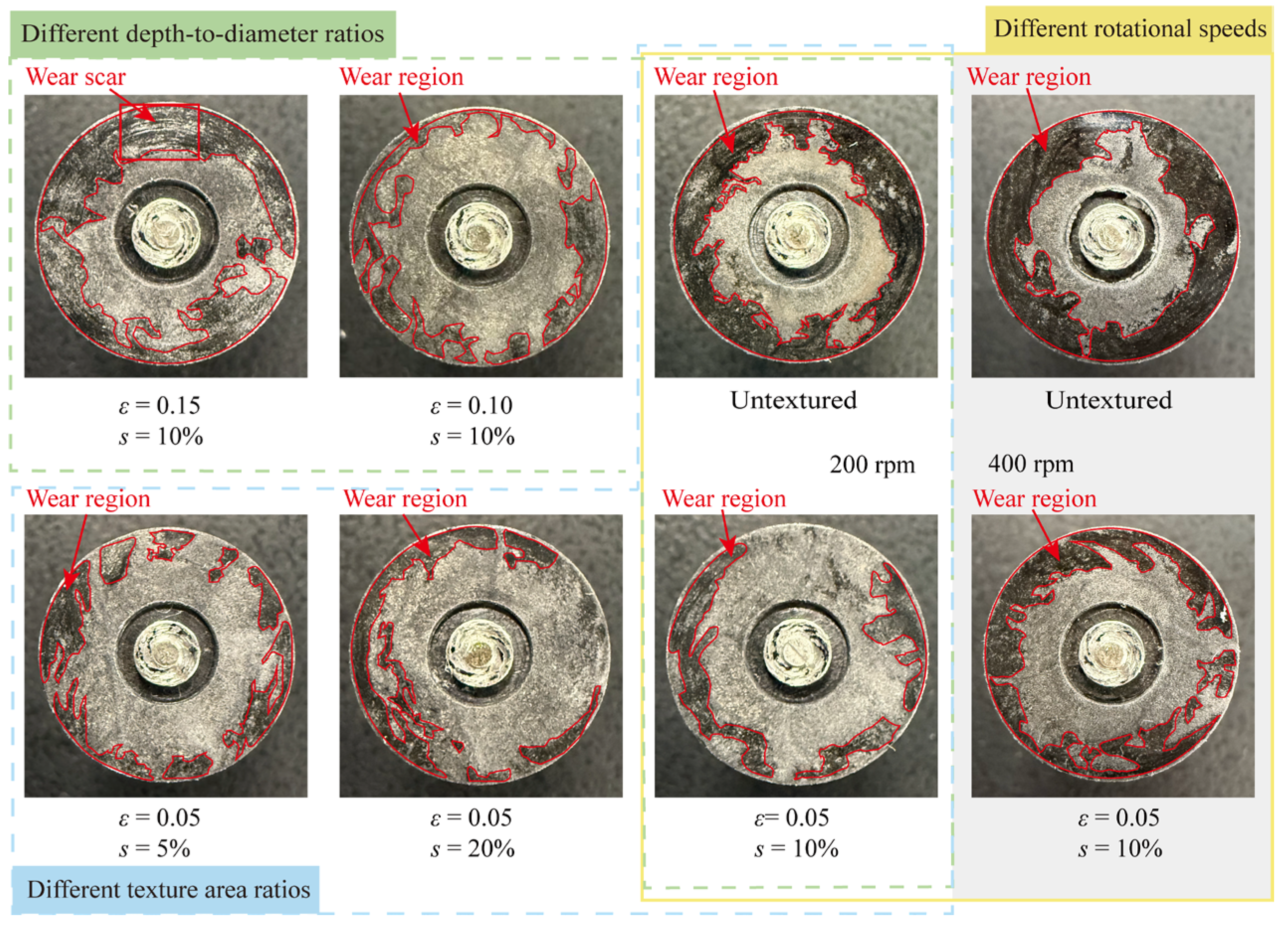
Figure 7 shows the worn surface morphologies of the upper CF/PEEK specimens after the friction and wear tests. The worn regions of the upper specimens were mainly distributed near the outer edge of the friction contact zone, forming distinct annular wear bands. The areas enclosed by the red curves represent the regions where material removal and surface flattening occurred during sliding. Under untextured conditions, the upper CF/PEEK specimens exhibited visibly larger worn regions with clear boundaries, indicating more pronounced surface flattening and material removal. For the CF/PEEK specimens paired with micro-textured 316L stainless-steel surfaces, the apparent worn regions were generally smaller and more uniformly distributed. The wear morphologies of the upper specimens varied with different texture parameters. At s = 10%, an increase in ε was associated with more surface scratches and more pronounced localized surface damage. At ε = 0.05, the apparent worn region increased with increasing s, particularly at s = 20%. At each tested rotational speed, the upper specimens paired with micro-textured 316L stainless-steel surfaces generally exhibited less extensive worn regions than the corresponding specimens paired with the untextured surface tested at the same speed, suggesting that micro-textures may mitigate wear-related surface damage at the macroscopic scale.
Figure 7.
Macroscopic wear morphologies of the CF/PEEK specimens after friction and wear.
3.3. Three-Dimensional Surface Morphology and Wear Evolution
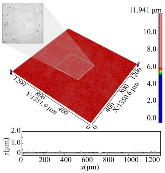
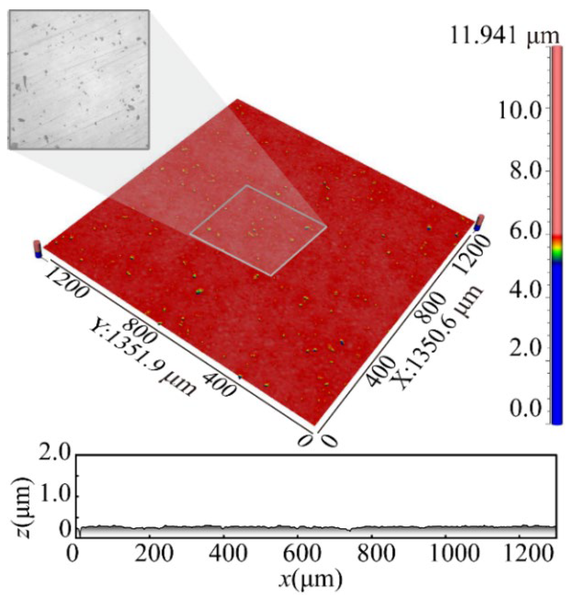
To further investigate wear-related surface changes under different texture parameters, 3D surface morphology measurements and cross-sectional profile analyses were performed on the upper CF/PEEK and lower 316L stainless-steel specimens before and after the friction and wear tests. Figure 8 presents the initial 3D surface morphology and cross-sectional profile of the unworn lower specimen. The initial surface was relatively flat, with only a small number of randomly distributed microscopic pits. The surface height variation was limited, and the cross-sectional profile exhibited only minor fluctuations.
Figure 8.
3D surface morphology and cross-sectional profile of the unworn 316L stainless steel surface.
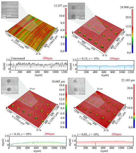
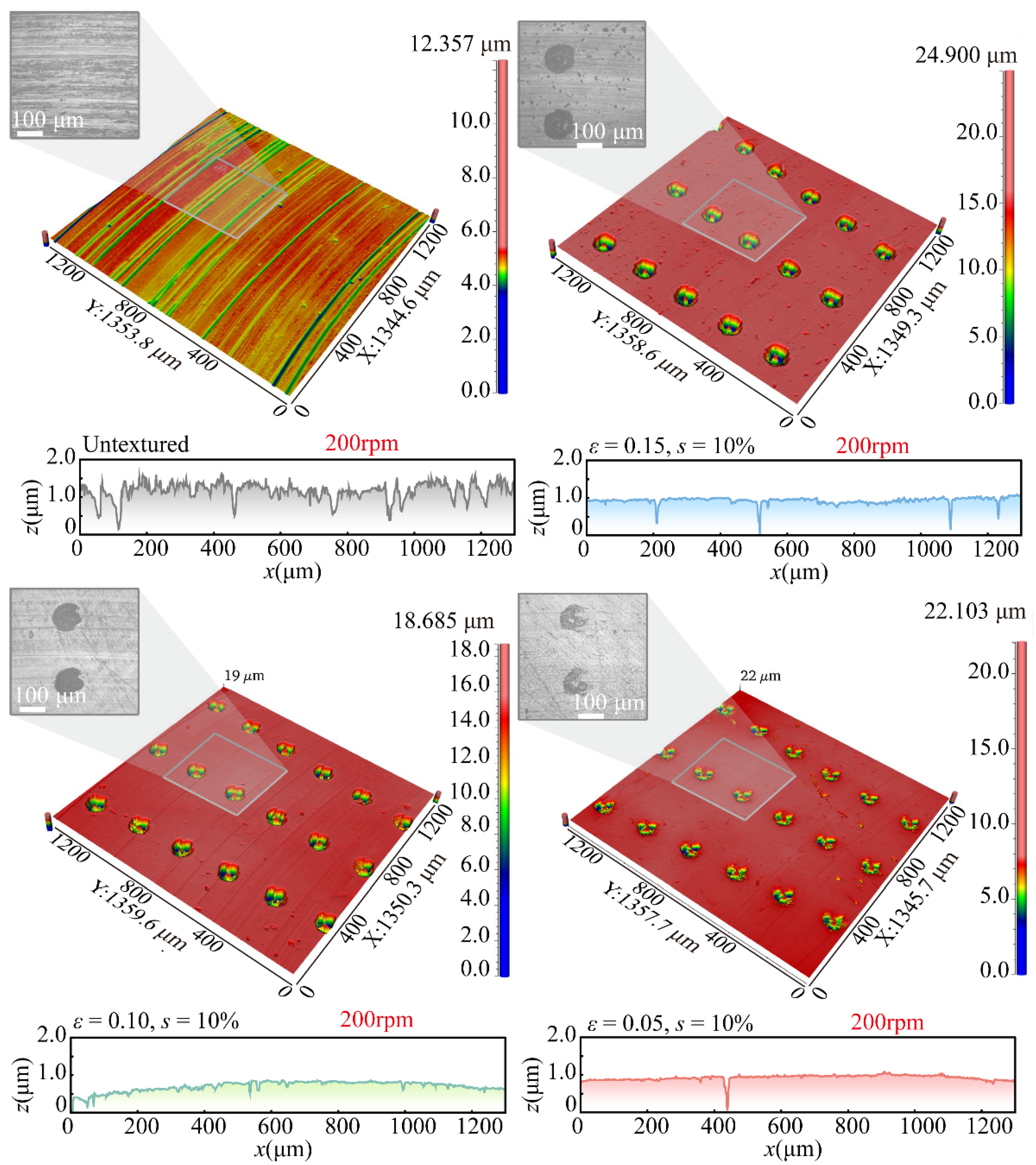
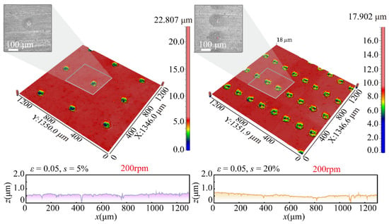
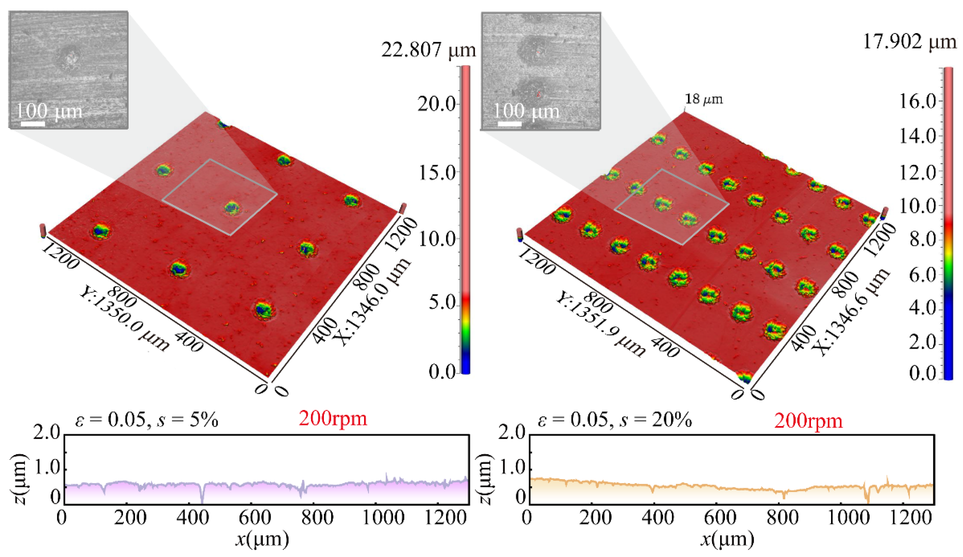
Figure 9 and Figure 10 present the 3D surface morphologies and cross-sectional profiles of the lower specimens at 200 rpm under different texture parameters (ε and s). As shown in Figure 9, the untextured surface exhibited pronounced grooves along the sliding direction after the friction and wear test, accompanied by substantial cross-sectional profile fluctuations, consistent with abrasive-wear features. After surface micro-texturing, the scratches on the platform regions were less pronounced. The textured surfaces with ε = 0.05 and 0.10 exhibited more uniform morphologies, relatively well-preserved dimple boundaries, fewer wear marks, and reduced profile fluctuations. However, at ε = 0.15, local protrusions appeared around the texture edges, indicating greater local height variation under this condition.
Figure 9.
3D surface morphologies and cross-sectional profiles of the lower specimens with different texture depth-to-diameter ratios.
Figure 10.
3D surface morphologies and cross-sectional profiles of the lower specimens with different texture area ratios.
As shown in Figure 10, at s = 5%, the limited number of textures provided insufficient lubricant storage and wear debris accommodation, resulting in noticeable local height variations. When s increased to 20%, although more textures were introduced, the reduced effective load-bearing area increased local contact pressure, causing larger deviations in the cross-sectional profile.
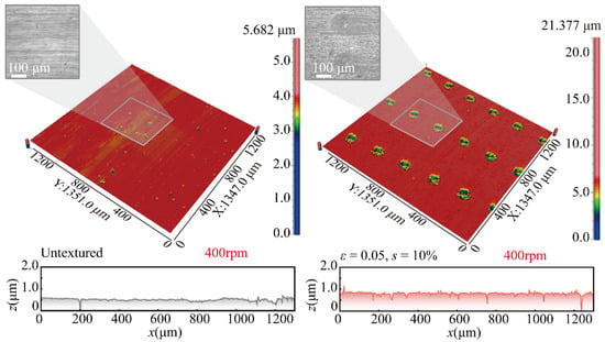
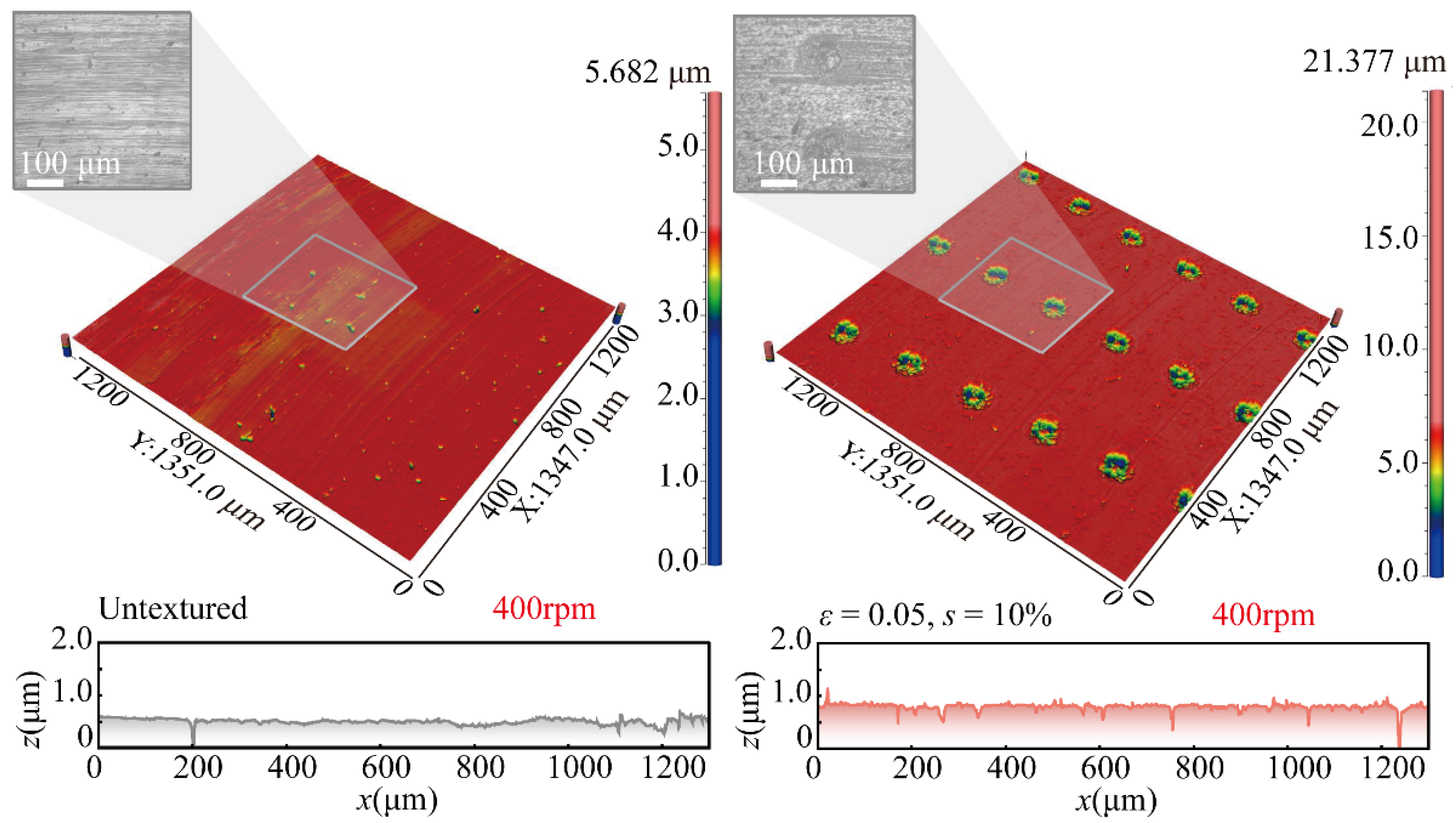
Figure 11 presents the 3D surface morphologies and cross-sectional profiles of the untextured and textured lower specimens tested at 400 rpm. At this rotational speed, both surfaces exhibited relatively uniform morphologies and cross-sectional profiles.
Figure 11.
3D surface morphologies and cross-sectional profiles of the lower specimens at 400 rpm.
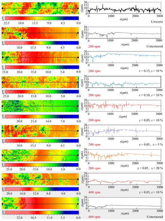
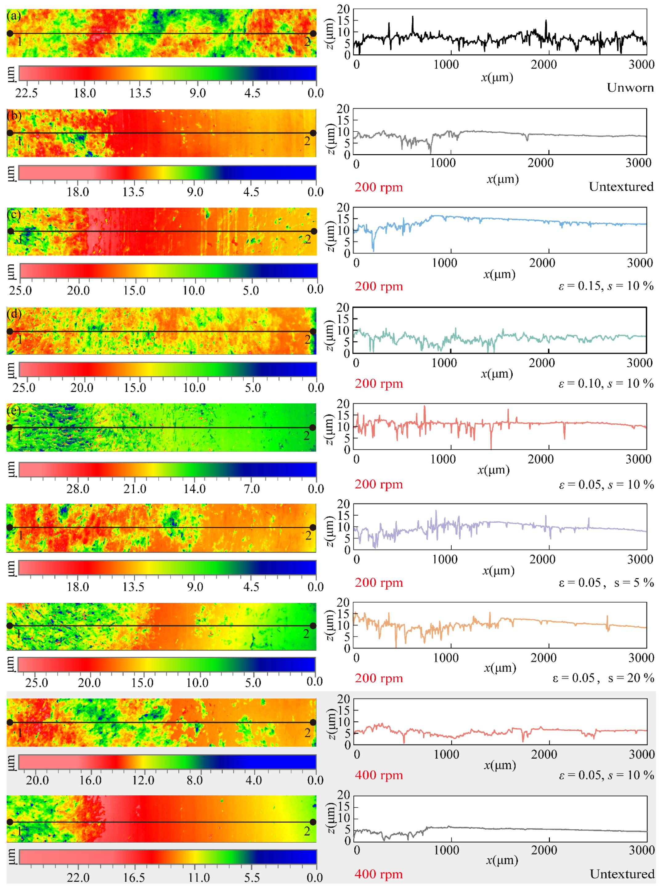
Figure 12 compares the 3D surface morphologies and cross-sectional profiles of the upper CF/PEEK specimens under different rotational speeds and texture parameters. The unworn CF/PEEK surface exhibited relatively high initial roughness, characterized by randomly distributed microscopic peaks and valleys with continuous small-scale profile fluctuations. At 200 rpm under untextured conditions, a large flattened region appeared on the right side of the worn CF/PEEK surface, and the corresponding cross-sectional profile became nearly flat, indicating that the surface asperities were gradually flattened or removed during sliding.
Figure 12.
3D surface morphologies and cross-sectional profiles of the upper specimens under different rotational speeds and texture parameters.
After surface micro-texturing of the 316L stainless steel specimens, the overall degree of surface flattening of the CF/PEEK specimens was reduced. With s fixed at 10%, the CF/PEEK specimens paired with textured discs having ε = 0.05 and 0.10 exhibited smaller flattened regions while maintaining certain microscopic surface features, indicating a milder and more uniform material removal process. When ε increased to 0.15, pronounced surface flattening, scratches, and localized material loss were observed, suggesting that an excessively large ε may aggravate abrasive wear and localized surface damage. With ε fixed at 0.05, the flattened region of the CF/PEEK surface first decreased and then increased with increasing s. At a low s, the beneficial effect of surface texturing was limited, whereas an excessive s reduced the effective load-bearing area, thereby increasing the local contact pressure and promoting surface flattening. At 400 rpm, the CF/PEEK specimen paired with the untextured surface still exhibited a large, continuous flattened region, whereas the specimen paired with the textured surface showed a smaller flattened area, indicating that surface texturing remained effective in mitigating wear of the CF/PEEK surface at higher rotational speeds.
3.4. Surface Roughness Analysis
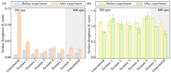
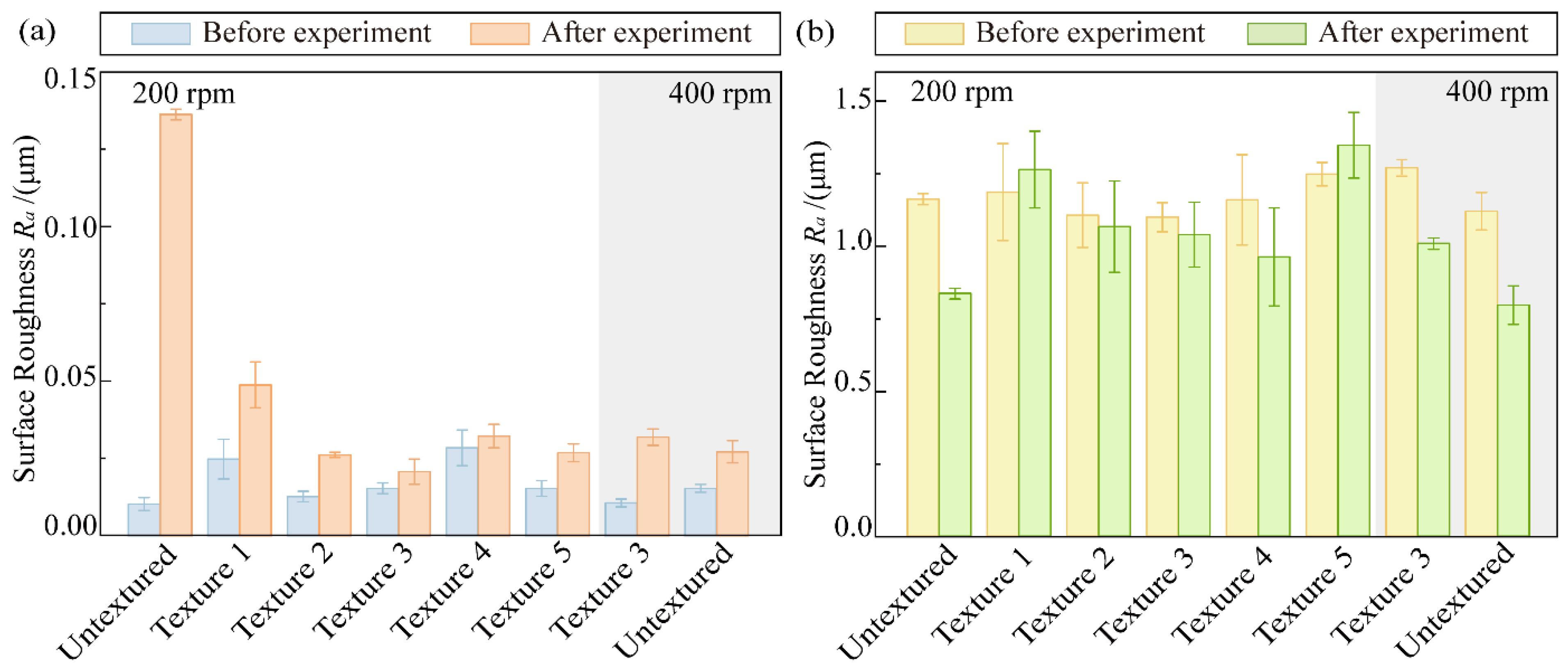
To quantitatively characterize the changes in surface morphology before and after the friction tests, the surface roughness parameter Ra of the specimens was measured and analyzed. Figure 13 presents the surface roughness Ra of the lower 316L stainless steel and upper CF/PEEK specimens before and after the friction tests under different rotational speeds and texture parameters. As shown in Figure 13a, the initial Ra values of the lower specimens ranged from approximately 0.008 to 0.025 μm. After the friction tests, the untextured specimens exhibited the most pronounced increase in surface roughness. At 200 rpm, the Ra of the untextured specimen increased from approximately 0.008 μm to 0.14 μm. In contrast, the textured specimens exhibited substantially lower post-test roughness. Under the conditions of ε = 0.05, s = 10% and ε = 0.10, s = 10%, the post-test Ra values were only approximately 0.02–0.03 μm, indicating that surface texturing effectively suppressed the roughening of the 316L stainless steel surface and mitigated wear-induced surface damage. At 400 rpm, the difference in surface roughness between the textured and untextured specimens decreased.
Figure 13.
Surface roughness of the specimens before and after the friction tests: (a) 316L stainless steel; (b) CF/PEEK.
As shown in Figure 13b, the initial Ra of the upper specimens was approximately 1.2 μm. After the friction tests, the surface roughness generally decreased. At 200 rpm, the Ra values of the upper specimens paired with the untextured surfaces decreased from approximately 1.15 μm to 0.75 μm, indicating pronounced surface flattening. In contrast, the upper specimens paired with the textured surfaces exhibited smaller changes in surface roughness. The smallest changes in Ra were observed at ε = 0.10, s = 10% and ε = 0.05, s = 10%, suggesting that appropriate combinations of texture parameters can mitigate surface flattening. When ε was relatively large (ε = 0.15), or s was relatively high (s = 20%), the post-test Ra increased slightly, suggesting localized nonuniform wear and increased surface height variations. At 400 rpm, the upper specimen paired with the untextured surface showed a more pronounced reduction in Ra than the specimen paired with the textured surface, indicating more extensive surface flattening.
The two materials exhibited distinct roughness-change characteristics after the friction tests. The increased roughness of 316L stainless steel was associated with groove formation and localized surface damage, whereas the decreased roughness of CF/PEEK was associated with the flattening or removal of surface asperities. Compared with the untextured condition, the textured conditions were generally associated with less pronounced roughening of the 316L stainless-steel surface and less extensive flattening of the CF/PEEK surface, resulting in more uniform surface morphologies.
3.5. Wear Mechanism Analysis
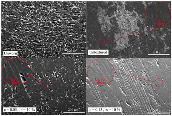
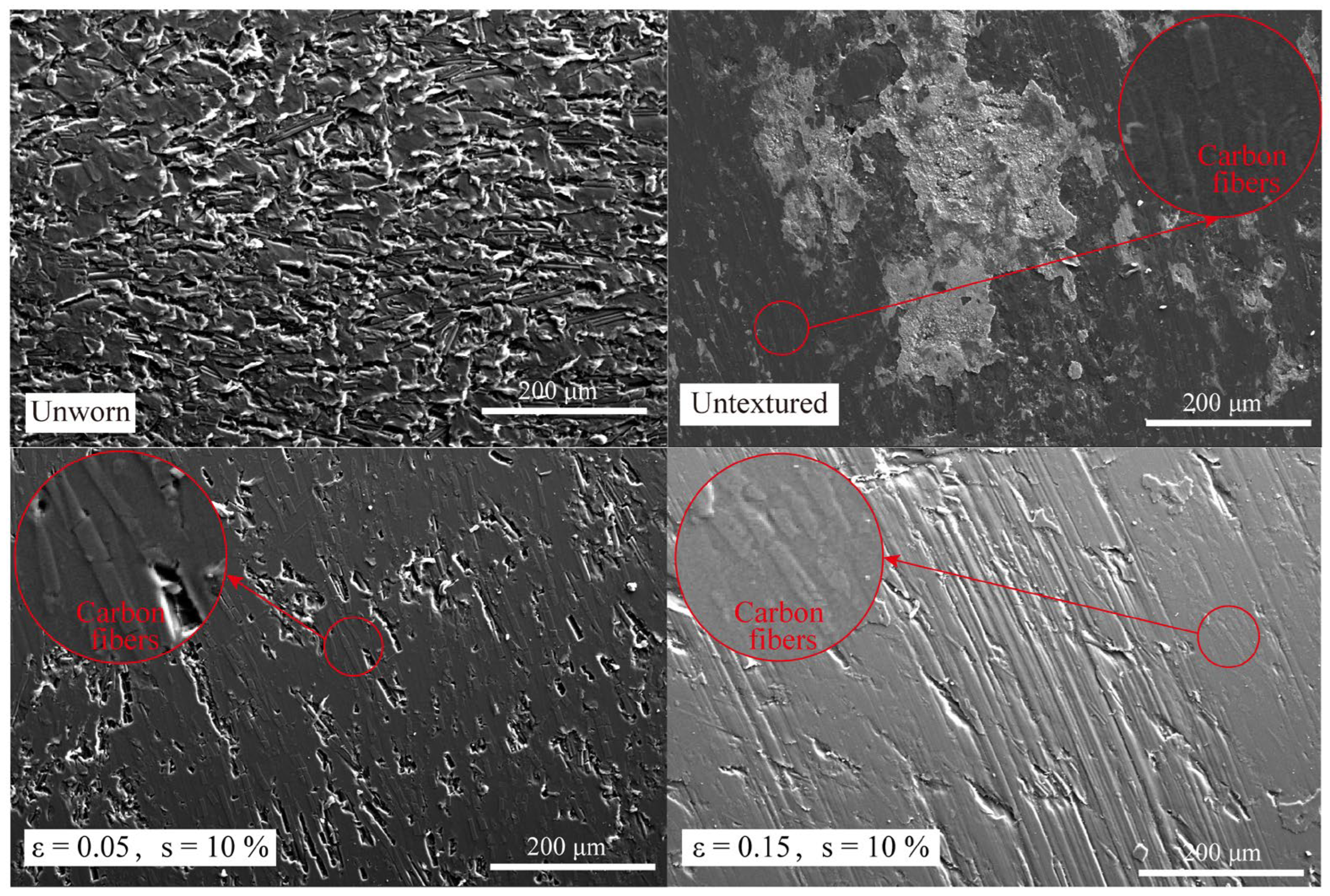
To investigate the wear-related surface features and material-transfer behavior of the tribo-pair, the worn CF/PEEK and 316L stainless-steel surfaces were characterized using SEM and EDS. As shown in Figure 14, the unworn CF/PEEK surface exhibited irregular machining marks and a relatively rough morphology without a distinct orientation. Under untextured conditions, adhesion-like features, ploughing grooves, and scratches aligned with the sliding direction were observed on the worn surface, consistent with the combined action of adhesive and abrasive wear.
Figure 14.
SEM morphologies of the CF/PEEK specimen surfaces after friction and wear.
In the 316L stainless steel–CF/PEEK tribo-pair, preferential wear of the relatively soft PEEK matrix may expose the embedded carbon fibers at the worn surface. Contact between the exposed carbon fibers and the metallic counterface may contribute to counterface wear and the generation of wear debris, which could subsequently participate in abrasive wear [38]. At ε = 0.05 and s = 10%, part of the original machining marks remained visible on the worn CF/PEEK surface. As shown in the enlarged region of Figure 14, a greater number of carbon fibers were exposed at the surface, while they remained embedded in the surrounding PEEK matrix. In addition, no pronounced deep ploughing grooves, localized material loss, or adhesion-like features were observed, indicating relatively mild surface damage under this condition. In contrast, at ε = 0.15 and s = 10%, the CF/PEEK surface exhibited more pronounced flattening, scratches along the sliding direction, and localized material loss, indicating greater local surface damage and more evident abrasive-wear features. Fewer clearly identifiable carbon fibers were observed under this condition and on the untextured surface. This may be associated with more severe surface damage, during which exposed fibers could become covered by smeared matrix material, locally damaged, or detached. Detached carbon-fiber debris may subsequently enter the contact interface and contribute to three-body abrasive wear [39]. However, wear at ε = 0.15 and s = 10% remained less severe than under the untextured condition, possibly because the micro-dimples retained part of the wear debris and reduced its repeated entrainment in the contact interface.
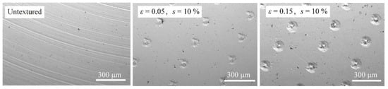
As shown in Figure 15, numerous continuous and relatively deep scratches aligned with the sliding direction were observed on the untextured surface, accompanied by scattered dark particles. At ε = 0.05 and s = 10%, both the number and depth of the scratches decreased markedly, indicating reduced surface wear, while a small number of dark particles accumulated within the texture dimples. At ε = 0.15 and s = 10%, the worn surface remained relatively smooth; however, scratches aligned with the sliding direction appeared near the dimple edges, while dark particles were also observed within the dimples. These observations suggest that suitably designed textures may mitigate surface wear by retaining part of the wear debris within the dimples and reducing its repeated participation in the sliding contact.
Figure 15.
SEM morphologies of the 316L stainless steel specimen surfaces after friction and wear.
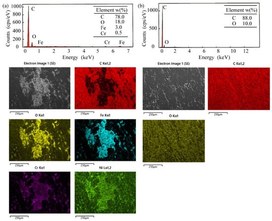
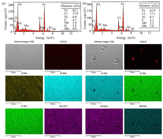
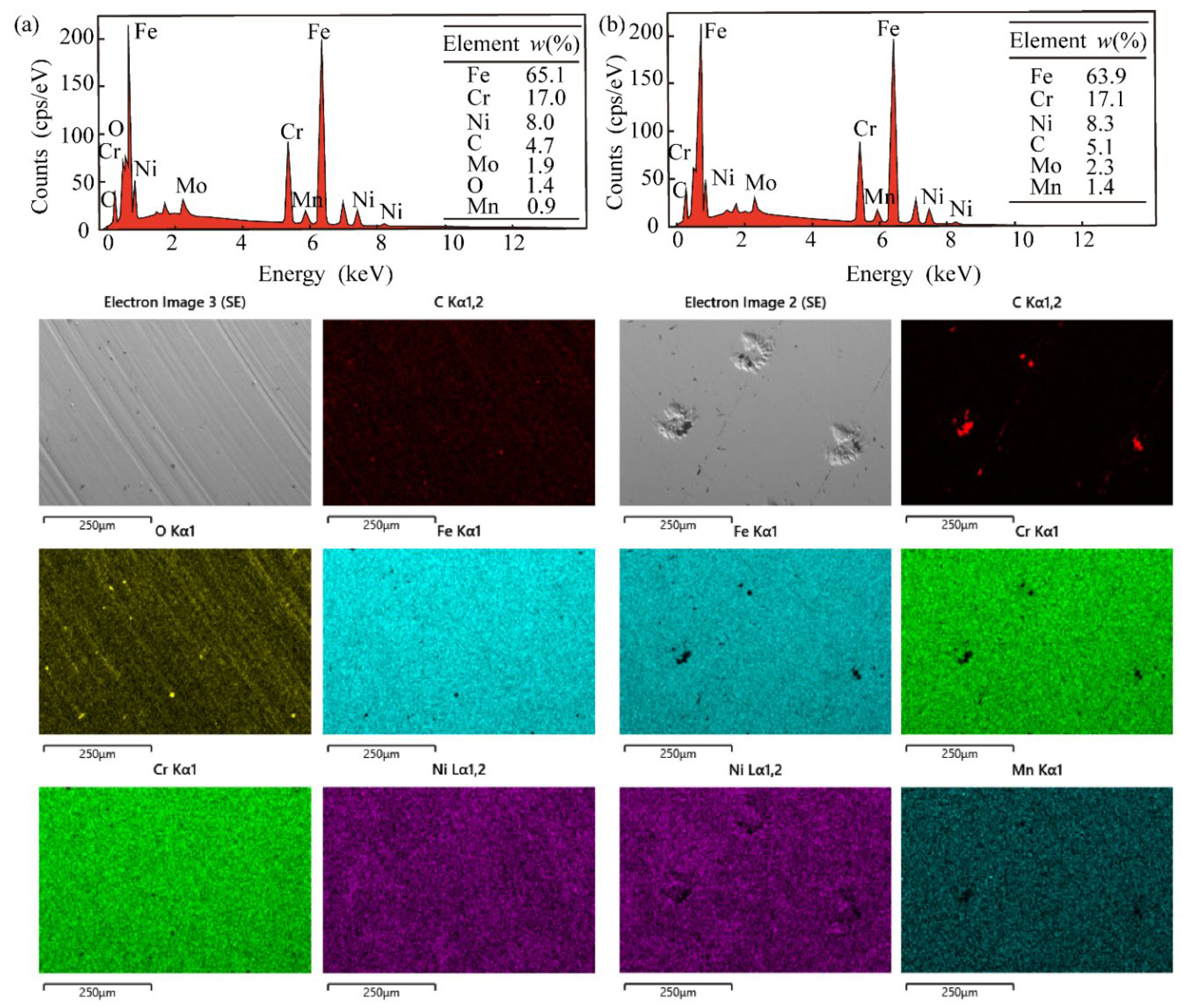
To identify the origin of the adhered material on the CF/PEEK surface and the composition of the black particles trapped in the textured dimples of the 316L stainless steel surface, EDS spectra and elemental maps were obtained for the worn surfaces under the untextured and textured condition of ε = 0.05 and s = 10%. As shown in Figure 16a, distinct Fe and Cr signals were detected on the worn CF/PEEK surface paired with the untextured 316L stainless-steel surface, accompanied by O enrichment. This indicates that the adherent material originated primarily from material transfer from the 316L stainless-steel counterface, whereas the detected O signal may originate from surface oxides, adsorbed water, or other oxygen-containing species. As shown in Figure 16b, for the CF/PEEK specimen paired with the 316L stainless-steel surface textured at ε = 0.05 and s = 10%, the worn CF/PEEK surface was composed predominantly of C with a small amount of O, while no pronounced Fe or Cr signals were detected. This suggests that material transfer from the 316L stainless-steel counterface to the CF/PEEK surface was reduced under this texture condition.
Figure 16.
EDS spectra and elemental maps of the worn CF/PEEK surfaces paired with (a) untextured and (b) textured 316L stainless-steel surfaces.
As shown in Figure 17a, the black particles on the worn 316L stainless steel surface under untextured conditions were composed mainly of C and O, suggesting that they likely originated from CF/PEEK wear debris or transferred material. As shown in Figure 17b, under textured condition of ε = 0.05 and s = 10%, the black particles trapped within the dimples were mainly composed of C and O. This result suggests that the textured dimples can effectively capture CF/PEEK-derived wear debris, thereby reducing the amount of debris entering the contact interface and its potential contribution to three-body abrasive wear.
Figure 17.
EDS spectra and elemental maps of the worn 316L stainless steel surfaces under (a) untextured; (b) textured.
The combined SEM and EDS results indicate that micro-texturing of the 316L stainless steel surface can improve the wear performance of the CF/PEEK–316L tribo-pair. Under untextured conditions, the continuous contact interface experienced relatively strong interfacial shear, promoting bidirectional material transfer and possible oxidation of the transferred material. Meanwhile, wear debris tended to remain within the contact interface and repeatedly participate in sliding, thereby aggravating abrasive wear. Under micro-textured conditions, the continuous contact path was locally interrupted, suppressing interfacial adhesion and surface plastic deformation. In addition, the textured dimples captured and retained wear debris, reducing its re-entry into the contact interface and repeated entrainment during sliding, thereby mitigating abrasive wear.
3.6. Comparative Wear Analysis of Textured Prototypes
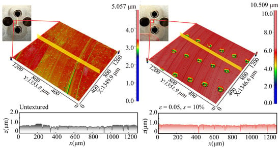
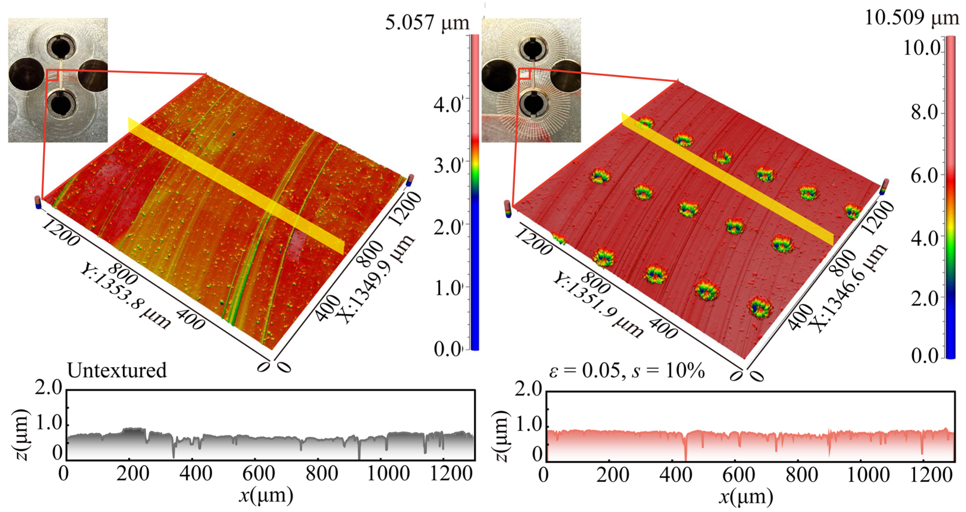
To verify the applicability of the above friction and wear test results to an actual prototype, the wear conditions of the pump-body end faces of the textured and untextured prototypes were comparatively analyzed. Figure 18 presents the local 3D morphologies and cross-sectional profiles of the worn pump-body end faces. The untextured surface exhibited relatively deep, band-like wear tracks and pronounced fluctuations in the corresponding cross-sectional profile. In contrast, the textured pump-body end face exhibited a more uniform overall morphology. Outside the textured regions, the platform areas were relatively smooth, and the cross-sectional profile exhibited smaller fluctuations, suggesting that surface texturing promoted more uniform end-face wear.
Figure 18.
Local 3D surface morphologies and cross-sectional height profiles of the worn pump-body end faces.
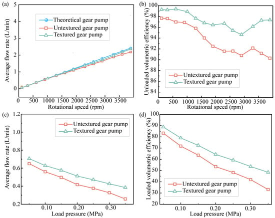
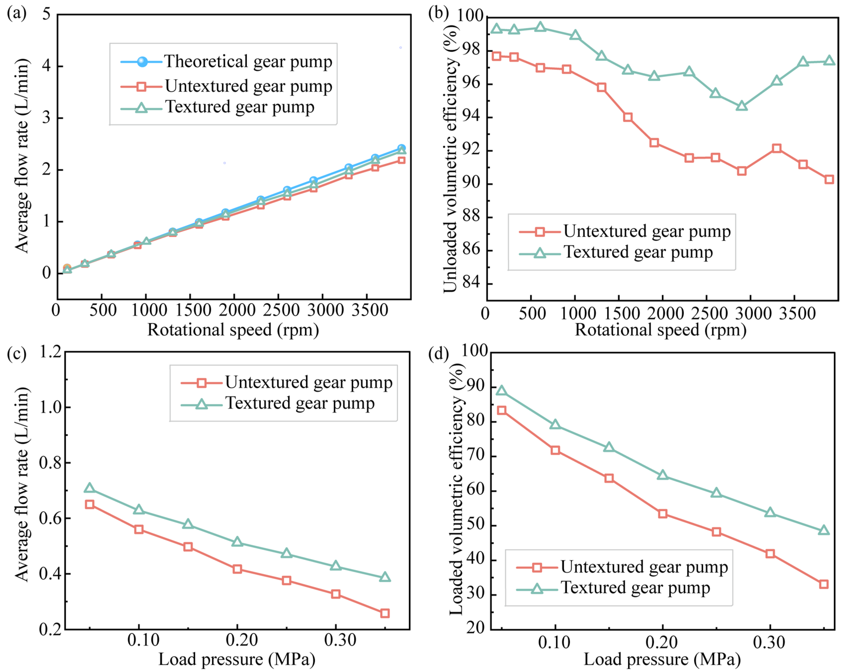
Figure 19 compares the hydraulic performance of the textured and untextured gear-pump prototypes [35]. As shown in Figure 19a, the average measured flow rates of both prototypes increased approximately linearly with rotational speed. The difference between the average measured and theoretical flow rates also increased as the rotational speed increased. As shown in Figure 19b, the volumetric efficiency exhibited an overall decreasing trend, with some fluctuations, as the rotational speed increased. This trend may be related to the characteristics of the present miniature pump using low-viscosity purified water. For such a pump, increasing rotational speed may intensify suction and chamber-filling limitations, while clearance-related losses may remain significant, thereby contributing to the observed reduction in volumetric efficiency [36,40]. Nevertheless, the textured gear pump exhibited higher volumetric efficiency than the untextured gear pump at every tested rotational speed. Under loaded conditions, the textured gear pump exhibited a higher average flow rate than the untextured gear pump at each tested outlet pressure, as shown in Figure 19c. Figure 19d further shows that the volumetric efficiency of the textured gear pump was consistently higher than that of the untextured gear pump under the tested loading conditions.
Figure 19.
Hydraulic performance of untextured and textured gear pumps: (a) flow rate versus rotational speed; (b) volumetric efficiency versus rotational speed; (c) flow rate versus outlet pressure; and (d) volumetric efficiency versus outlet pressure.
The higher volumetric efficiency of the textured pump may be associated with reduced end-face wear, which could help limit wear-induced changes in the effective end-face clearance during operation. Previous studies on other pump friction pairs have similarly reported that appropriately designed surface textures can improve lubrication performance, reduce wear, and decrease leakage [41,42]. These prototype results indicate that texturing the pump-body end face was associated with improved flow-delivery and volumetric-efficiency performance.
4. Conclusions
This study investigated the effects of surface micro-texturing on the friction and wear performance of a water-lubricated CF/PEEK–316L stainless steel tribo-pair. The engineering applicability of surface micro-texturing was further evaluated through gear-pump prototype tests. The main conclusions are as follows:
- (1)
- Properly designed surface micro-textures can significantly reduce the coefficient of friction. Within the tested parameter range, the lowest average friction coefficient was obtained at a depth-to-diameter ratio of 0.05 and a texture area ratio of 10%. At 200 rpm, its average friction coefficient was approximately 34.8% lower than that of the untextured surface. The friction-reduction advantage of surface texturing was more pronounced at low rotational speeds.
- (2)
- Macroscopic and microscopic morphological analyses showed that appropriate surface micro-texturing improved the surface wear characteristics of the tribo-pair. After texturing, wear-debris accumulation and continuous grooves on the 316L stainless steel surface were reduced, while plastic deformation and material accumulation on the CF/PEEK surface were alleviated. The wear distribution across both material surfaces also became more uniform.
- (3)
- The two materials exhibited distinct surface roughness evolution trends. After the friction tests, the surface roughness of 316L stainless steel increased, whereas that of CF/PEEK decreased owing to the flattening or removal of surface asperities. Appropriate texture parameters suppressed excessive roughening of the 316L stainless steel surface and excessive flattening of the CF/PEEK surface.
- (4)
- SEM and EDS analyses revealed pronounced bidirectional material transfer at the friction interface under untextured conditions, possibly accompanied by oxidation of the transferred metallic component. Surface micro-texturing suppressed material transfer from the 316L stainless steel surface to the CF/PEEK surface and captured wear debris within the dimples, thereby mitigating adhesive wear and three-body abrasive wear. The prototype tests further showed that the textured gear pump exhibited higher average flow rates and volumetric efficiency, together with more uniform wear morphology of the pump-body end face, supporting the engineering application potential of surface micro-texturing.
The present study is limited by the lack of quantitative wear-rate measurements, lubricant-film-thickness estimation, and direct interfacial-temperature measurement. Therefore, the proposed mechanisms are interpreted from friction, surface morphology, roughness, SEM, and EDS observations. Future work should include complete wear-volume measurements at identical sliding distances and direct thermal and lubrication-state characterization to further quantify the role of surface micro-textures.
Author Contributions
Conceptualization, X.X. and Y.C.; methodology, X.X. and Y.Y.; software, Y.Y. and W.H.; validation, Y.Y. and W.H.; formal analysis, X.X., Y.Y. and W.H.; investigation, W.H. and Y.Y.; resources, X.X. and Y.C.; data curation, Y.Y.; writing—original draft preparation, W.H.; writing—review and editing, X.X.; visualization, Y.Y. and W.H.; supervision, Y.C.; project administration, X.X.; funding acquisition, X.X. and Y.C. All authors have read and agreed to the published version of the manuscript.
Funding
This research was funded by the program for the National Natural Science Foundation of China (Nos. 52405056 and 52275073), the scientific research start-up funds of Guangdong Ocean University (Nos. 360302022203 and 360302022302), the open fund of Guangdong Provincial Key Laboratory of Precision Gear Flexible Manufacturing Equipment Technology Enterprises (No. 2021B1212050012-08), and the Zhanjiang Science and Technology Plan Project (No. 2024B01042).
Data Availability Statement
All relevant data are included in this manuscript.
Acknowledgments
The authors would like to thank the editor and reviewers for their helpful comments and suggestions to improve the manuscript.
Conflicts of Interest
Authors Yangzhi Chen and Xiaoping Xiao were employed by the company Postdoctoral Program, Zhongshan MLTOR Numerical Control Technology Co., Ltd. The remaining authors declare that the research was conducted in the absence of any commercial or financial relationships that could be construed as potential conflicts of interest.
References
- Ayadi, K.; Brunetière, N.; Tournerie, B.; Maoui, A. Experimental and Numerical Study of the Lubrication Regimes of a Liquid Mechanical Seal. Tribol. Int. 2015, 92, 96–108. [Google Scholar] [CrossRef] [Scilit]
- Wang, H.; Lin, N.; Yuan, S.; Liu, Z.; Yu, Y.; Zeng, Q.; Fan, J.; Li, D.; Wu, Y. Structural Improvement, Material Selection and Surface Treatment for Improved Tribological Performance of Friction Pairs in Axial Piston Pumps: A Review. Tribol. Int. 2024, 198, 109838. [Google Scholar] [CrossRef] [Scilit]
- Li, Y.; Hao, M.; Brunetière, N.; Li, Q.; Wang, J.; Ren, B. Transient Thermo-Elasto-Hydrodynamic Study of Herringbone-Grooved Mechanical Face Seal during Start-up Stage. Int. J. Therm. Sci. 2026, 220, 110355. [Google Scholar] [CrossRef] [Scilit]
- Thiagarajan, D.; Vacca, A.; Watkins, S. On the Lubrication Performance of External Gear Pumps for Aerospace Fuel Delivery Applications. Mech. Syst. Signal Process. 2019, 129, 659–676. [Google Scholar] [CrossRef] [Scilit]
- Kurtz, S.M.; Devine, J.N. PEEK Biomaterials in Trauma, Orthopedic, and Spinal Implants. Biomaterials 2007, 28, 4845–4869. [Google Scholar] [CrossRef] [Scilit] [PubMed]
- Xie, G.Y.; Sui, G.X.; Yang, R. Effects of Potassium Titanate Whiskers and Carbon Fibers on the Wear Behavior of Polyetheretherketone Composite under Water Lubricated Condition. Compos. Sci. Technol. 2011, 71, 828–835. [Google Scholar] [CrossRef] [Scilit]
- Stryczek, J.; Banaś, M.; Krawczyk, J.; Marciniak, L.; Stryczek, P. The Fluid Power Elements and Systems Made of Plastics. Procedia Eng. 2017, 176, 600–609. [Google Scholar] [CrossRef] [Scilit]
- Rodionov, L.; Stryczek, J.; Rekadze, P.; Stryczek, P.; Gafurov, S.; Prokofiev, A.; Shakhmatov, E. Challenges in Design Process of Gear Micropump from Plastics. Arch. Civ. Mech. Eng. 2021, 21, 34. [Google Scholar] [CrossRef] [Scilit]
- Wang, Z.; Gao, D. Friction and Wear Properties of Stainless Steel Sliding against Polyetheretherketone and Carbon-Fiber-Reinforced Polyetheretherketone under Natural Seawater Lubrication. Mater. Des. 2014, 53, 881–887. [Google Scholar] [CrossRef] [Scilit]
- Guan, Z.; Wu, D.; Cheng, Q.; Wang, Z.; Tang, M.; Liu, Y. Friction and Wear Characteristics of CF/PEEK against 431 Stainless Steel under High Hydrostatic Pressure Water Lubrication. Mater. Des. 2020, 196, 109057. [Google Scholar] [CrossRef] [Scilit]
- Huang, Q.; Shi, X.; Xue, Y.; Zhang, K.; Wu, C. Recent Progress on Surface Texturing and Solid Lubricants in Tribology: Designs, Properties, and Mechanisms. Mater. Today Commun. 2023, 35, 105854. [Google Scholar] [CrossRef] [Scilit]
- Etsion, I. State of the Art in Laser Surface Texturing. In Proceedings of the Advanced Tribology—Proceedings of CIST2008 & ITS-IFToMM2008; Luo, J., Meng, Y., Shao, T., Zhao, Q., Eds.; Springer: Berlin/Heidelberg, Germany, 2010; pp. 761–762. [Google Scholar]
- Gachot, C.; Rosenkranz, A.; Hsu, S.M.; Costa, H.L. A Critical Assessment of Surface Texturing for Friction and Wear Improvement. Wear 2017, 372–373, 21–41. [Google Scholar] [CrossRef] [Scilit]
- Mao, B.; Siddaiah, A.; Liao, Y.; Menezes, P.L. Laser Surface Texturing and Related Techniques for Enhancing Tribological Performance of Engineering Materials: A Review. J. Manuf. Process. 2020, 53, 153–173. [Google Scholar] [CrossRef] [Scilit]
- Xiao, X.; He, S.; Shao, Y.; Chen, Y. Investigation on Laser Micro Ablation of Miniature Gears—Semi-Analytical Topography Modeling and Machining Accuracy Evaluation. J. Manuf. Process. 2026, 173, 1131–1142. [Google Scholar] [CrossRef] [Scilit]
- Wang, X.; Kato, K.; Adachi, K. The Lubrication Effect of Micro-Pits on Parallel Sliding Faces of SiC in Water. Tribol. Trans. 2002, 45, 294–301. [Google Scholar] [CrossRef] [Scilit]
- Tang, W.; Zhou, Y.; Zhu, H.; Yang, H. The Effect of Surface Texturing on Reducing the Friction and Wear of Steel under Lubricated Sliding Contact. Appl. Surf. Sci. 2013, 273, 199–204. [Google Scholar] [CrossRef] [Scilit]
- Vishnoi, M.; Kumar, P.; Murtaza, Q. Surface Texturing Techniques to Enhance Tribological Performance: A Review. Surf. Interfaces 2021, 27, 101463. [Google Scholar] [CrossRef] [Scilit]
- Gropper, D.; Wang, L.; Harvey, T.J. Hydrodynamic Lubrication of Textured Surfaces: A Review of Modeling Techniques and Key Findings. Tribol. Int. 2016, 94, 509–529. [Google Scholar] [CrossRef] [Scilit]
- Yan, D.; Qu, N.; Li, H.; Wang, X. Significance of Dimple Parameters on the Friction of Sliding Surfaces Investigated by Orthogonal Experiments. Tribol. Trans. 2010, 53, 703–712. [Google Scholar] [CrossRef] [Scilit]
- Schneider, J.; Braun, D.; Greiner, C. Laser Textured Surfaces for Mixed Lubrication: Influence of Aspect Ratio, Textured Area and Dimple Arrangement. Lubricants 2017, 5, 32. [Google Scholar] [CrossRef] [Scilit]
- Mo, F.; Shen, C.; Zhou, J.; Khonsari, M.M. Statistical Analysis of Surface Texture Performance With Provisions With Uncertainty in Texture Dimensions. IEEE Access 2017, 5, 5388–5398. [Google Scholar] [CrossRef] [Scilit]
- Niu, Y.; Pang, X.; Yue, S.; Shangguan, B.; Zhang, Y. The Friction and Wear Behavior of Laser Textured Surfaces in Non-Conformal Contact under Starved Lubrication. Wear 2021, 476, 203723. [Google Scholar] [CrossRef] [Scilit]
- Niu, Y.; Pang, X.; Song, C.; Shangguan, B.; Zhang, Y.; Wang, S. Tailoring Tribological Properties of Ti-Zr Alloys via Process Design of Laser Surface Texturing and Thermal Oxidation. Surf. Interfaces 2023, 37, 102743. [Google Scholar] [CrossRef] [Scilit]
- Xue, J.; Cai, Y.; Aslam, J.; Liang, X.; Li, X.; Tang, Y.; Liu, Z. Laser Surface Texture for Enhancement of Tribological Performance of AISI 5115 Steel Engine Valve Train Components. Opt. Laser Technol. 2025, 192, 113456. [Google Scholar] [CrossRef] [Scilit]
- Jia, J.; Chen, J.; Zhou, H.; Hu, L.; Chen, L. Comparative Investigation on the Wear and Transfer Behaviors of Carbon Fiber Reinforced Polymer Composites under Dry Sliding and Water Lubrication. Compos. Sci. Technol. 2005, 65, 1139–1147. [Google Scholar] [CrossRef] [Scilit]
- Sumer, M.; Unal, H.; Mimaroglu, A. Evaluation of Tribological Behaviour of PEEK and Glass Fibre Reinforced PEEK Composite under Dry Sliding and Water Lubricated Conditions. Wear 2008, 265, 1061–1065. [Google Scholar] [CrossRef] [Scilit]
- Wang, Z.; Gao, D. Comparative Investigation on the Tribological Behavior of Reinforced Plastic Composite under Natural Seawater Lubrication. Mater. Des. 2013, 51, 983–988. [Google Scholar] [CrossRef] [Scilit]
- Dong, W.; Nie, S.; Zhang, A. Tribological Behavior of PEEK Filled with CF/PTFE/Graphite Sliding against Stainless Steel Surface under Water Lubrication. Proc. Inst. Mech. Eng. Part J J. Eng. Tribol. 2013, 227, 1129–1137. [Google Scholar] [CrossRef] [Scilit]
- Wang, M.; Zhang, C.; Wang, X. The Wear Behavior of Textured Steel Sliding against Polymers. Materials 2017, 10, 330. [Google Scholar] [CrossRef] [Scilit] [PubMed]
- Wang, Z.; He, H.; Wu, S.; Xiang, J.; Ni, J. Effect of Surface Topography and Wettability on Friction Properties of CFRPEEK. Tribol. Int. 2022, 171, 107573. [Google Scholar] [CrossRef] [Scilit]
- Liang, Y.; Gao, D.; Chen, B.; Zhao, J. Friction and Wear Study on Friction Pairs with a Biomimetic Non-Smooth Surface of 316L Relative to CF/PEEK under a Seawater Lubricated Condition. Chin. J. Mech. Eng. 2019, 32, 66. [Google Scholar] [CrossRef] [Scilit]
- Liang, Y.; Gao, D.; Zhao, J. Tribological Properties of Friction Pair between 316L Stainless Steel and CF/PEEK with Nonsmooth Surface under Seawater Lubrication. Tribol. Trans. 2020, 63, 658–671. [Google Scholar] [CrossRef] [Scilit]
- Liang, Y.; Wang, H.; Zhang, Z.; Xing, H.; Liang, X.; Li, Y.; Chen, N.; Zhang, F.; Wang, W.; Gao, D. Optimization of Bionic Surface Texture for Enhanced Tribological Performance in Seawater Axial Piston Pump Slipper Pairs via Numerical Simulation, Experiment, and Intelligent Algorithms. Wear 2026, 591, 206585. [Google Scholar] [CrossRef] [Scilit]
- Chen, Y.; Yang, Y.; He, W.; Zheng, M.; Xiao, X. Design and Manufacturing of a Miniature Double-Circular-Arc Line Gear Pump. Micromachines 2026, 17, 222. [Google Scholar] [CrossRef] [Scilit] [PubMed]
- Du, R.; Chen, Y.; Zhou, H. Numerical Analysis of the Lubricating Gap between the Gear Shaft and the Journal Bearing in Water Hydraulic Internal Gear Pumps. Proc. Inst. Mech. Eng. Part C J. Mech. Eng. Sci. 2018, 232, 2297–2314. [Google Scholar] [CrossRef] [Scilit]
- Yang, Y.; Zhang, M.; Yankey, R.P.; Wong, P.K. Research on Seawater Hydraulic Internal Ball Gear Pump. Proc. Inst. Mech. Eng. Part C J. Mech. Eng. Sci. 2022, 236, 6967–6982. [Google Scholar] [CrossRef] [Scilit]
- Li, D.; Liu, Y.; Deng, Y.; Fang, M.; Wu, D. The Effect of Different Temperatures on Friction and Wear Properties of CFRPEEK against AISI 431 Steel under Water Lubrication. Tribol. Trans. 2018, 61, 357–366. [Google Scholar] [CrossRef] [Scilit]
- Jin, Z.; Zhang, X.; Hou, Z.; Yao, Z.; Shen, H. Tribological Properties of Carbon Fiber-Reinforced PEEK against 304 Stainless Steel with Reticulate Surface Texture. Materials 2022, 15, 8789. [Google Scholar] [CrossRef] [Scilit] [PubMed]
- Zhang, S.; Li, Y.; Shi, W.; Li, W.; Qin, J. Experimental Study on High-Altitude Characteristics of Aviation Lubricating Oil Gear Pump. Flow Meas. Instrum. 2026, 107, 103120. [Google Scholar] [CrossRef] [Scilit]
- Jia, H.; Zhou, Z.; Yin, B.; Zhou, H.; Xu, B. Effect of Compound Texture on Lubrication and Sealing Performance of Plunger Pump. Lubr. Sci. 2021, 33, 43–59. [Google Scholar] [CrossRef] [Scilit]
- Zhang, H.; Lu, Y.; Long, J.; Liu, Z.; Tu, F. Optimization of Micro-Texture in Thermo Plastic Elasto-Hydrodynamic Lubrication for Improving the Start-up Behavior of the Piston/Cylinder Pair in Axial Piston Pump. Flow Meas. Instrum. 2025, 106, 102976. [Google Scholar] [CrossRef] [Scilit]

Disclaimer/Publisher’s Note: The statements, opinions and data contained in all publications are solely those of the individual author(s) and contributor(s) and not of MDPI and/or the editor(s). MDPI and/or the editor(s) disclaim responsibility for any injury to people or property resulting from any ideas, methods, instructions or products referred to in the content. |
© 2026 by the authors. Licensee MDPI, Basel, Switzerland. This article is an open access article distributed under the terms and conditions of the Creative Commons Attribution (CC BY) license.