


Abstract
In this study, an elastoplastic finite element (FE) contact model was developed to evaluate the plastic deformation of a surface induction-hardened tapered roller bearing used in wind turbines, incorporating depth-dependent material properties and heat treatment-induced residual stress distribution. The validity of this model was confirmed by comparing the calculated plastic deformation with measured profiles from static compression experiments. The results show that the residual stresses generated by induction hardening have a significant influence on the elastoplastic behavior of bearings. Based on this model, a parametric analysis was performed to investigate the effects of surface hardening depth (SHD), contact pressure, and residual stress on surface plastic deformation. Empirical formulas were developed to predict surface plastic deformation and evaluate material yielding for surface-hardened tapered roller bearings, thereby preventing excessive deformation during service. This allows for the rapid estimation of the maximum plastic deformation for different hardening depths and provides an efficient approach for assessing the yielding risk.
1. Introduction
The main bearing is a key component that ensures the safe and stable operation of a wind turbine. Tapered roller bearings (TRBs) are widely used because they can effectively withstand combined radial and axial loads [1,2]. These bearings are often exposed to severe service conditions in real application, including low rotational speeds, heavy loads, and cyclic impact loads [3]. To enhance the service reliability of wind turbine bearings, various strategies are adopted, including surface coatings, advanced lubrication technologies, and high-performance lubricant additives.
As the rated power of wind turbines continues to increase, the size of main bearings has also grown accordingly. For these large bearings, through hardening is often impractical because of material and process limitations [4,5]. Consequently, surface induction hardening has been widely applied in engineering practice, as it improves both the resistance to plastic deformation and the wear resistance of the bearing raceway [6,7]. After surface induction hardening, the mechanical properties of the near-surface material (e.g., hardness, yield strength, and constitutive response) vary significantly with depth [8]. Based on the hardness distribution, the material can generally be divided into three regions, i.e., the hardened layer, the transition layer, and the core material. Previous investigations [9,10,11,12] have confirmed that the initiation of yielding in surface-hardened components is strongly dependent on surface hardening depth (SHD). When the SHD is relatively small, plastic deformation is more likely to occur near the interface of the transition layer and the core material. With an increase in SHD, the initiation of yielding location shifts to the hardened layer, typically near the region of the maximum von Mises stress. Therefore, designing an appropriate SHD that satisfies service requirements is of practical importance.
Many studies have been carried out to assess the plastic deformation response of surface induction-hardened bearings. Glodež et al. [13] employed finite element (FE) analysis to investigate the contact behavior of large slewing ball bearings with surface induction hardening. Their findings showed that under comparable conditions, the resistance to plastic deformation of surface-hardened ball bearings is generally lower than that of through-hardened ones. They also found that in loading conditions with relatively small axial forces combined with large overturning moments, bearing clearance can significantly reduce the resistance to deformation. Göncz et al. [14,15] and He et al. [16] further studied the effects of roller profile and roller tilt angle on the contact behavior and deformation of large three-row cylindrical roller slewing bearings subjected to surface induction hardening. Their results showed that the resistance to plastic deformation increases with increasing SHD. When the SHD exceeds a specific critical depth, the deformation resistance approaches that of through-hardened bearings [15]. In addition, optimized roller profiling was found to further improve the contact performance, while the roller tilt angle was identified as an important parameter influencing bearing the load-carrying capacity [15,16]. Based on FE simulations, Li et al. [17] established a predictive formula for the surface plastic deformation of surface induction-hardened cylindrical roller slewing bearings via linear regression analysis. Considering the material yield criteria, Lai et al. [18,19] developed analytical models to predict the plastic deformation of surface induction-hardened bearings under line, point, and elliptical contact conditions. However, residual stress is not considered in most existing analyses of the plastic deformation of large surface-hardened bearings, which may cause inconsistencies between theoretical predictions and actual operating conditions.
Surface induction hardening not only alters the mechanical properties of the near-surface material but also the residual stress state within the component. Typically, compressive residual stresses are generated in the hardened layer, while tensile residual stresses form in the transition layer and the core material [20,21,22,23,24]. Numerous studies have shown that residual stress significantly affects the deformation behavior and crack evolution of bearings. Compressive residual stresses can inhibit crack initiation and retard crack propagation, thus enhancing resistance to plastic deformation and delaying damage accumulation [25,26,27,28,29,30,31]. In contrast, tensile residual stresses usually promote deformation and accelerate damage evolution [32,33,34]. Torkamani et al. [35] found that compared with conventionally quenched bearings, surface induction-hardened bearings generate residual stress, thereby improving the bearing’s resistance to micro-pitting and surface wear resistance. Studies by Areitioaurtena et al. [36] revealed that the residual stress induced by surface induction hardening can increase the rolling contact fatigue life of bearings by a factor of 1.56. Londhe et al. [37] reported that surface induction hardening can significantly reduce the fatigue crack growth rate of bearings, thereby enhancing their fracture toughness. Dechant et al. [38] emphasized that under high-load rolling–sliding contact conditions, the contact response and damage evolution of components are determined by the combined effects of subsurface microstructure and residual stress. Overall, the performance enhancement achieved through surface induction hardening results from the combined effects of improved surface mechanical properties and the induced residual stresses.
Previous studies on residual stress have mainly focused on its influence on the deformation behavior of small-scale bearings with shallow induction-hardened layers. To understand the role of residual stress on the elastoplastic contact behavior of large surface induction-hardened TRBs for wind turbines, this study carries out both numerical simulation and experimental investigation. First, an elastoplastic FE model for the contact problem of surface induction-hardened large-size TRBs is developed, in which the residual stress field is modeled. Second, the influences of residual stress, SHD, and the constitutive behavior of the hardened layer and core material on the elastoplastic contact problem are analyzed. Third, empirical formulas for the prediction of surface plastic deformation and material yield in surface induction-hardened bearings are proposed based on the numerical simulation results.
2. FE Model of Elastoplastic Contact Problem for Inhomogeneous Materials
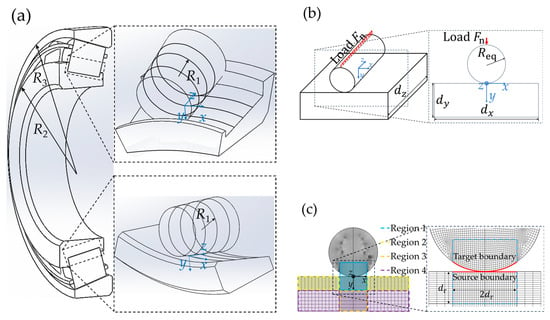
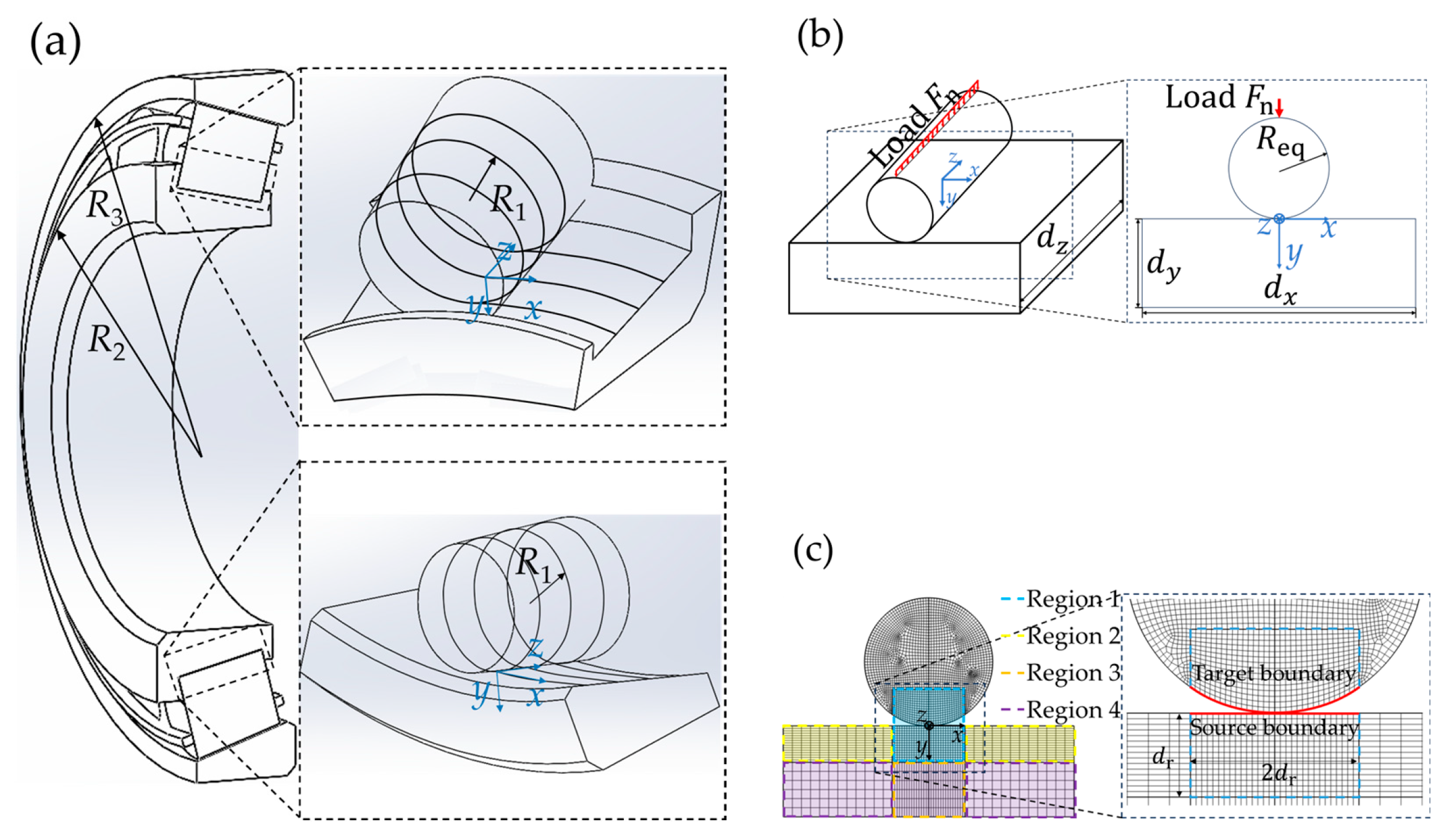
The geometry of the large TRB investigated in this study is shown in Figure 1a. The outer and inner ring diameters are 3.25 m and 2.65 m, respectively. It could be applicable as either the front main bearing of an 18 MW wind turbine or the rear main bearing of a 20 MW wind turbine. The raceways of the inner and outer rings are surface induction-hardened, while the rollers are through-hardened. The contact between the roller generatrix and the raceways of the inner and outer rings is simplified to a line contact problem, which can be equivalently modeled as a roller–plane contact configuration, as shown in Figure 1b. From another perspective, the ellipticity ratio of the roller–raceway contact usually exceeds 35, the contact can be reasonably simplified to a plane strain problem. Accordingly, an elastoplastic FE model is established under plane strain conditions, as shown in the enlarged view of Figure 1b. In this model, denotes the equivalent contact radius between the roller and the bearing raceway. The equivalent contact radii for the roller–inner ring and roller–outer ring contacts are determined using Equations (1) and (2), respectively [39]:
where is the roller radius, is the inner ring raceway radius, and is the outer ring raceway radius.
Figure 1.
Schematic diagram of the FE model: (a) schematic diagram of the tapered roller bearing; (b) schematic diagram of the plane strain problem; (c) mesh used in the FE model.
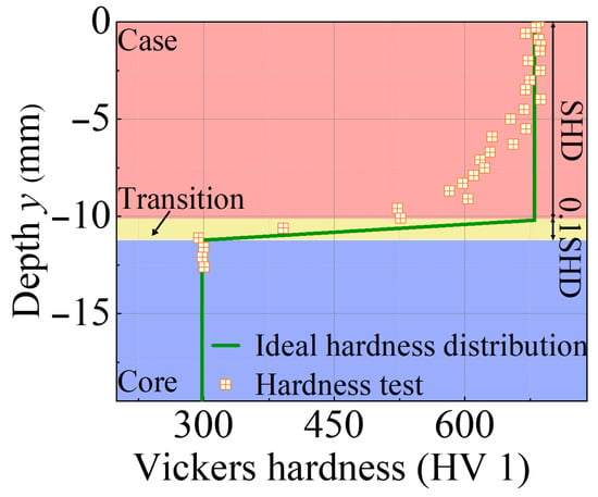
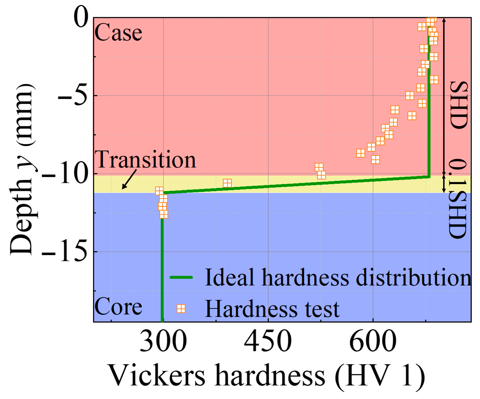
Figure 2 shows a depth-dependent hardness profile of the bearing material after surface induction hardening in lab. In this study, the SHD is defined as the distance from the top surface of bearing raceway to the position where the Vickers hardness reaches a specified threshold value (HV1) as given in Table 1. The thickness of the transition layer varies with SHD and is approximately 0.1 times the SHD value according to Refs. [18,19].
Figure 2.
Hardness distribution along depth direction for a case upon surface induction hardening.
Table 1.
Material parameters used in the FE model.
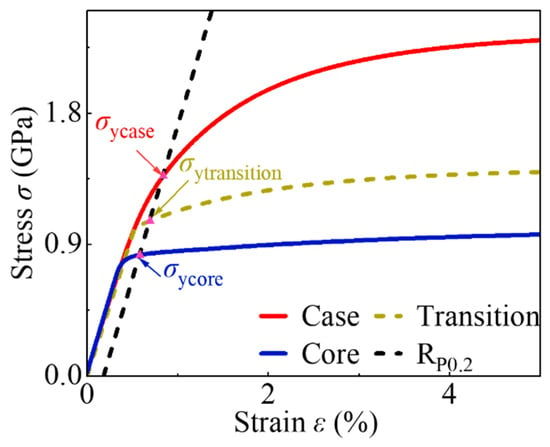
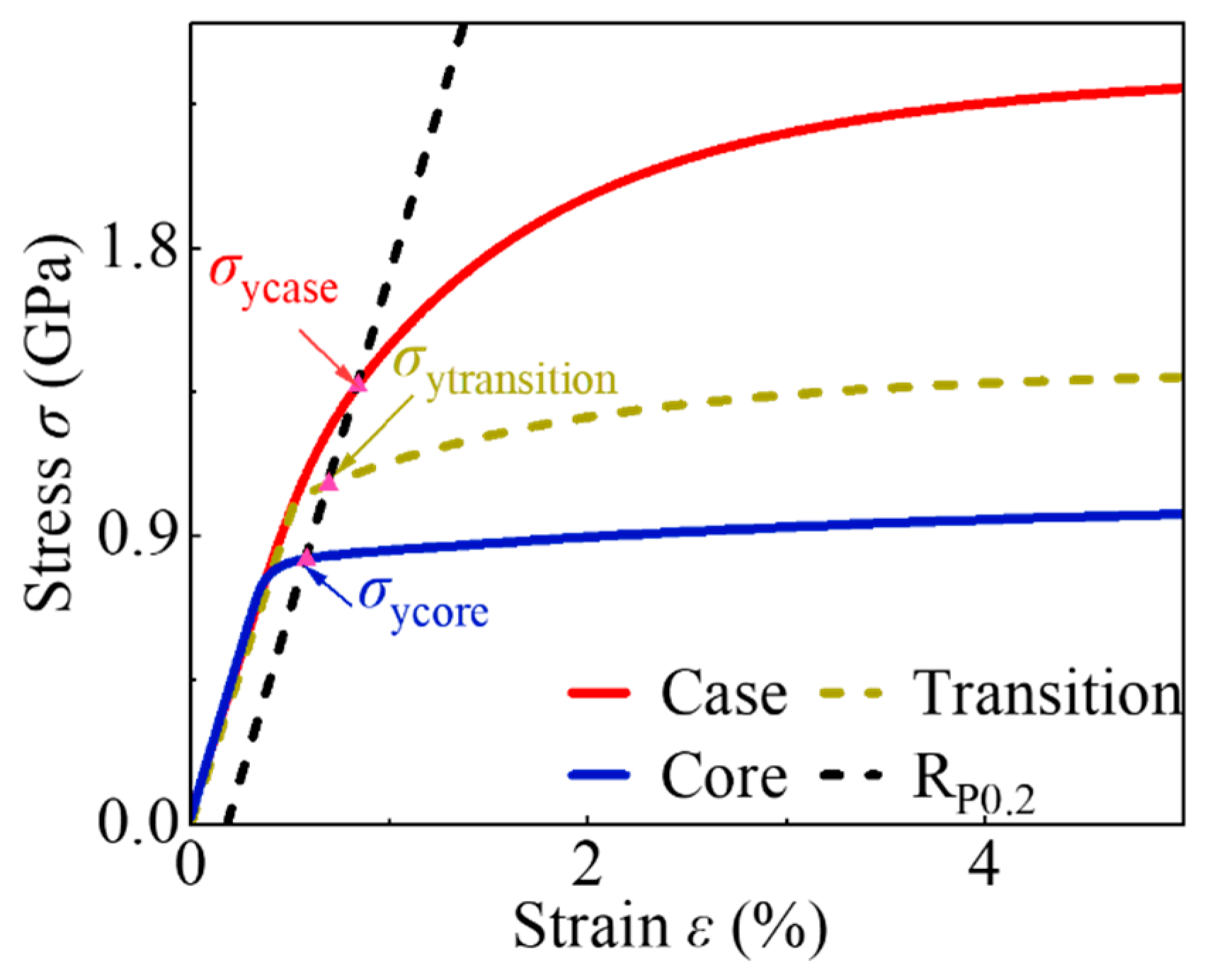
The gradient hardness induced by surface induction hardening leads to depth-dependent constitutive behavior, including variations in the stress–strain response and the yield strength. In this study, the stress–strain curves of the hardened layer material (hardness , yield strength ) and the core material (hardness , yield strength ) are obtained from uniaxial tensile tests, as shown in Figure 3. These tensile data are used to calibrate the constitutive model together with the von Mises equivalent stress yield criterion adopted in the FE analysis. Based on the hardness profile in Figure 2, the stress–strain relation of the transition layer is then determined via the interpolation method proposed in Equation (3) following Ref. [19]. Since the hardness and yield strength of the rollers are higher than those of the raceways, the plastic deformation of rollers during contact could be treated as negligible [13,14,15,16,17,18,19]. In addition, the authors have investigated the effect of elastoplastic modeling of rollers, and it was found that its contribution to the final plastic deformation of the raceway is negligible. Accordingly, the rollers are modeled as linear elastic materials in the analysis to ensure computational efficiency while maintaining sufficient accuracy.
Figure 3.
Stress–strain diagrams of the hardened layer, transition layer, and core material.
In this study, the Voce isotropic hardening model [40] is adopted to characterize the plastic deformation behavior of the bearing material. Its corresponding constitutive relation is expressed as follows:
where denotes the initial yield stress obtained from the tensile tests, the saturation flow stress, and the saturation exponent. These two parameters are determined by fitting the stress–strain curves shown in Figure 3. In the present framework, the tensile yield stress serves as the input parameter for the isotropic hardening law and is evaluated together with the von Mises criterion under the multiaxial contact stress state. The material parameters adopted in the FE model are listed in Table 1.
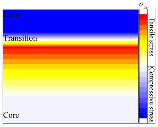
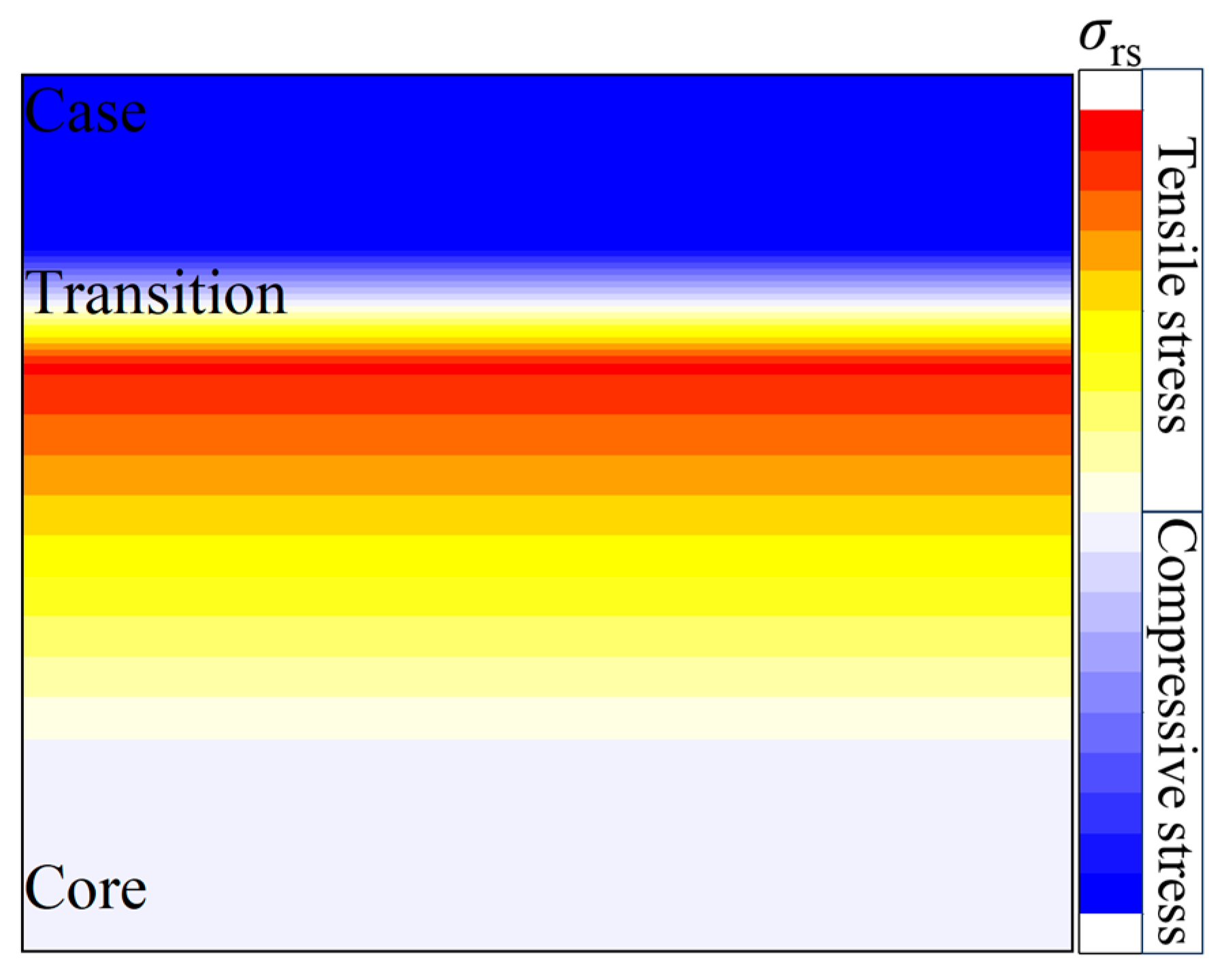
The residual stress distribution of the bearing raceway after surface induction hardening process is determined via numerical simulation. A comparable residual stress distribution is observed in the XRD measurements of induction-hardened specimens presented in Ref. [41]. As shown in Figure 4, compressive residual stresses are generated in the hardened layer, while tensile residual stresses form in the transition layer and the core material. In this study, the residual stress profile is incorporated into the FE model as an initial stress field in both the x and z directions.
Figure 4.
Example of a diagram of residual stress distribution along depth.
3. Static Compression Test
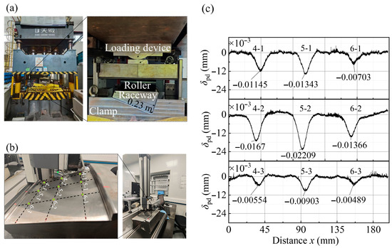
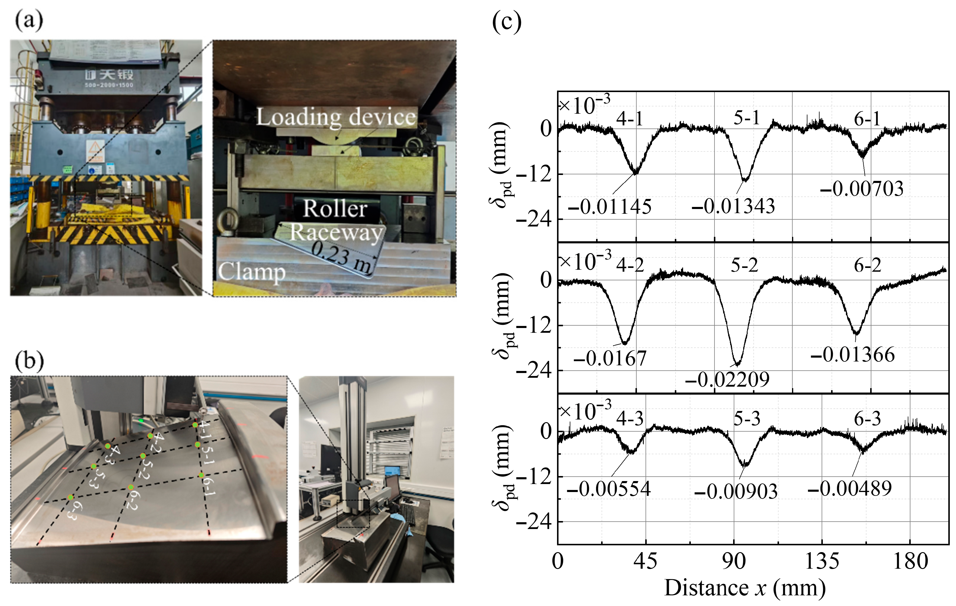
To validate the established elastoplastic FE model, static compression tests were conducted on the bearing ring samples, and the experimental setup and procedures are detailed in this section. The inner and outer rings of the large TRB (customized for this study only) were cut into several segments. Static compression tests were conducted on a 500-ton hydraulic testing machine (Tianduan 500T, GENECTEC TIANDUAN, Tianjin, China) to measure the surface plastic deformation under various loads. A partial enlarged view of the experimental setup, including the testing machine, fixtures, and loading device, is shown in Figure 5a.
Figure 5.
Static compression test and profile measurement of the plastic deformation: (a) photo of Tianduan 500T hydraulic testing machine; (b) photo of probe-type surface profilometer and measurement positions; (c) examples of measured surface profile.
Static loading tests were conducted at three locations (left, middle, and right) on each inner or outer ring segment. At each test location, the load was applied steadily, held for 10 s, and then unloaded at a constant rate, i.e., a complete loading–unloading cycle. After the tests, a stylus surface profilometer was used to measure the raceway profile at the upper, middle, and lower regions of the samples. The contact position between the roller and the inner ring, along with the profile measurement positions, is schematically shown in Figure 5b. The measured profiles are shown in Figure 5c. The results indicate that the middle positions of the samples (4-2, 5-2, and 6-2) experienced the highest contact pressures and had the largest surface plastic deformation. These positions thus represent the most critical regions for plastic deformation analysis for the FE model. The geometric parameters of the outer and inner rings used for subsequent model validation are listed in Table 2 and Table 3, respectively.
Table 2.
Geometric parameters of the outer ring.
Table 3.
Geometric parameters of the inner ring.
4. Boundary Conditions and Validation of the FE Model
4.1. Effect of Left and Right Boundary Conditions on Plastic Deformation
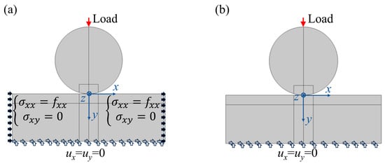
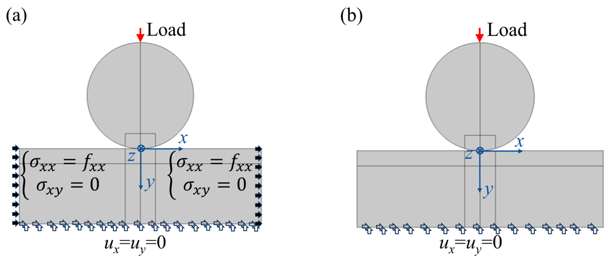
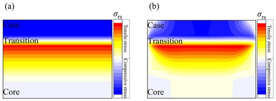
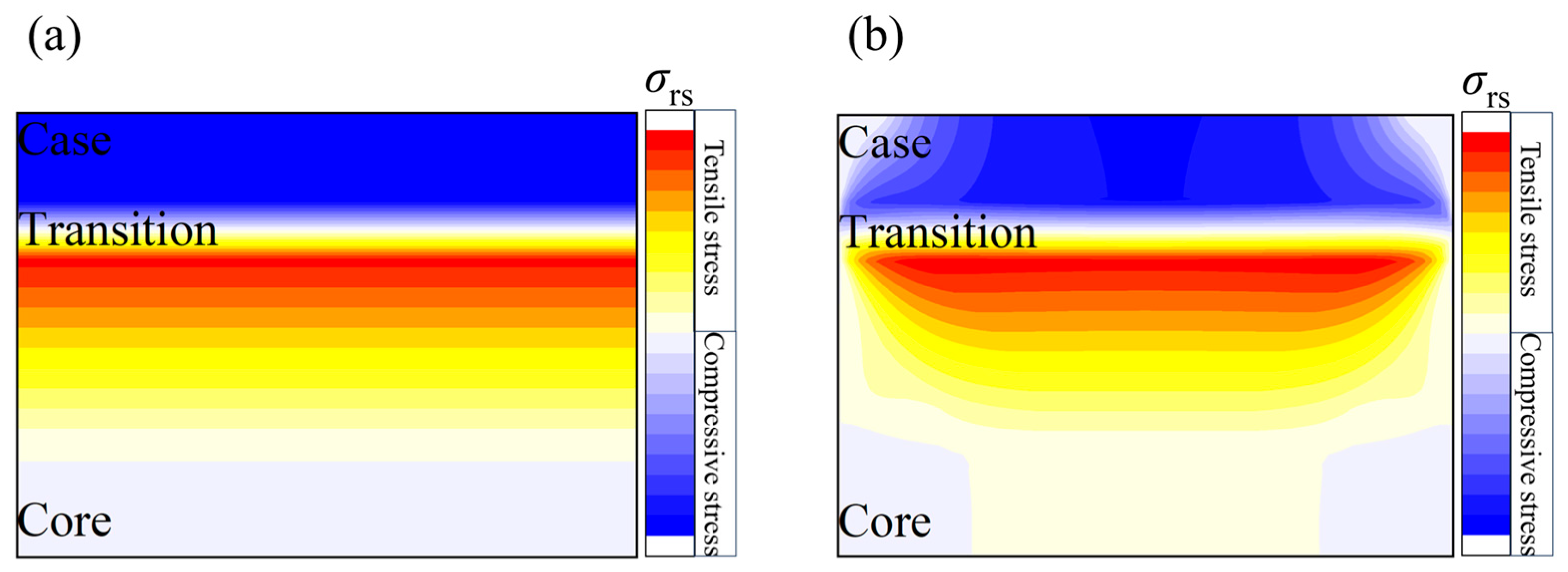
After surface induction hardening, the residual stresses in the inner and outer rings are approximately uniform along the circumferential direction. However, when the rings are segmented, the circumferential constraints at the left and right boundaries are eliminated. Consequently, the residual stresses near these free edges are partially released and undergo local redistribution. To investigate the effect of this redistribution on the elastoplastic contact, two types of boundary conditions were considered. Under boundary condition 1 (Figure 6a), the bottom edge was fully constrained (Dirichlet boundary condition, displacement constraint), while the left and right boundaries were subjected to stress boundary conditions consistent with the prescribed residual stresses (Neumann boundary condition, stress constraint). The corresponding residual stress field is shown in Figure 7a. This configuration may represent the actual service condition of the unsegmented bearing, where circumferential residual stress continuity is preserved. Under boundary condition 2 (Figure 6b), the bottom edge was also fully fixed, while the left and right boundaries were left unconstrained, allowing residual stresses to relax freely at these edges. The corresponding residual stress distribution is shown in Figure 7b. This case reflects the experimental condition of the segmented samples used in the compression tests.
Figure 6.
Schematic of the two types of boundary conditions: (a) boundary condition 1 for uniform residual stress distribution; (b) boundary condition 2 for non-uniform residual stress distribution.
Figure 7.
Schematic contour plots of residual stress distribution corresponding to two types of boundary conditions: (a) boundary condition 1; (b) boundary condition 2.
To evaluate the effect of the two boundary conditions on the elastoplastic deformation, three inner-ring test cases listed in Table 3 were selected for the FE analysis. The corresponding computational parameters are listed in Table 4.
Table 4.
Calculation parameters for verifying the influence of left and right boundary conditions.
Table 5 compares the simulated surface plastic deformation under the two boundary conditions with the corresponding experimental results. Under boundary condition 1, the minimum relative error between the numerical and experimental results exceeds 6%. In contrast, under boundary condition 2, the maximum relative error is within 5%. These results indicate that the residual stress boundary affects the predicted surface plastic deformation. Since boundary condition 2 more closely reflects the actual configuration of the segments used in the experiments, it achieves better agreement with the measured data.
Table 5.
Effect of boundary conditions on the maximum surface plastic deformation.
Furthermore, the effect of boundary conditions is dependent on the contact location. At the middle position (IR-5-3–5-2 in Table 5), which is relatively far from the left and right edges, the residual stress fields obtained under the two types of boundary conditions are similar. Consequently, the difference in the predicted plastic deformation between the two cases (see the last column of Table 5) is relatively small. In contrast, at the left and right positions, partial relief of residual stress near the free boundaries leads to a redistribution of the stress field, resulting in larger discrepancies in the predicted plastic deformation. Based on the above analysis, boundary condition 2 was used to validate the numerical model with the experimental results. Boundary condition 1 was adopted for the subsequent parametric analysis and empirical formula fitting, as it would represent the actual service condition of the intact bearing.
4.2. Validation of the FE Model
The material properties of the inner and outer ring raceways used in the FE models have been given listed in Table 1. The geometric parameters are provided in Table 2 and Table 3, and the computational parameters used in the simulations are listed in Table 6 and Table 7.
Table 6.
Calculation parameters of the outer ring case.
Table 7.
Calculation parameters of the inner ring case.
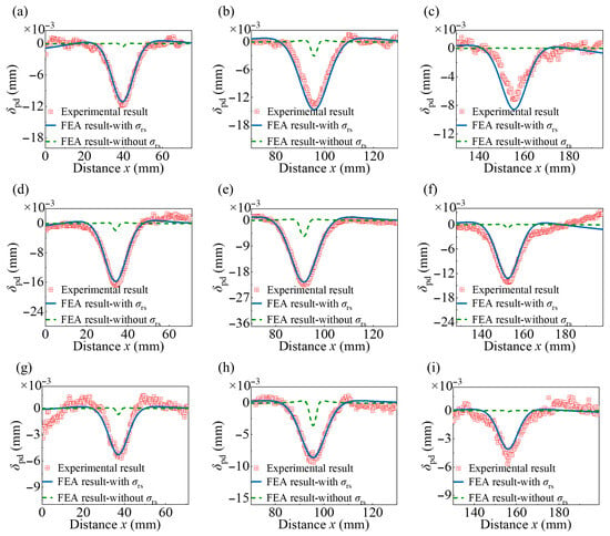
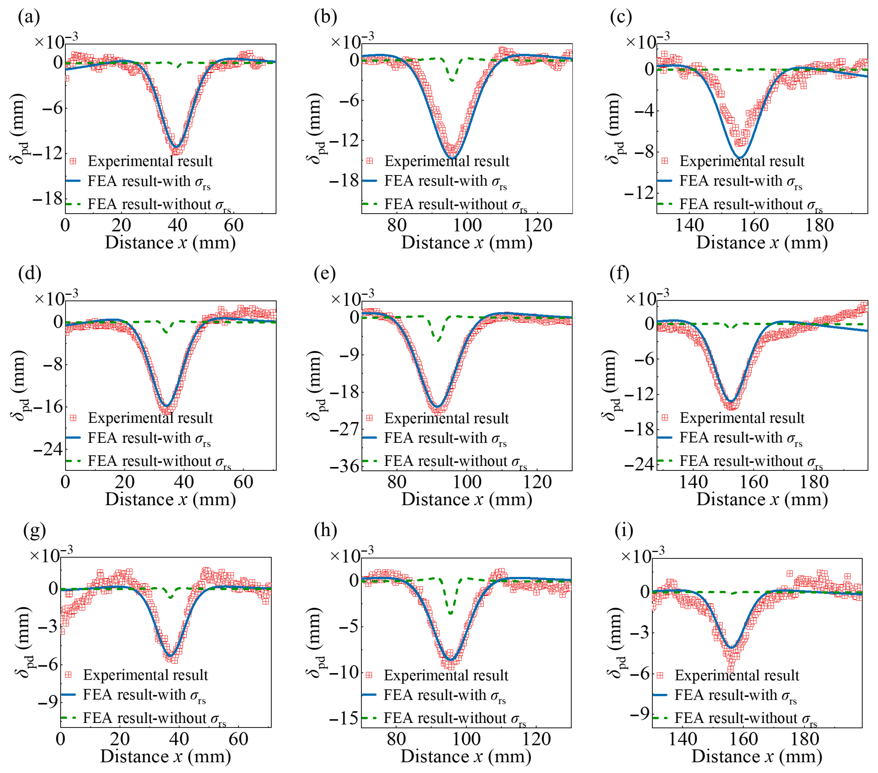
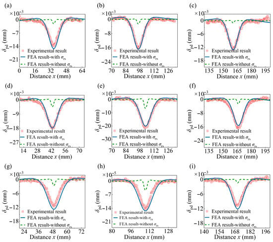
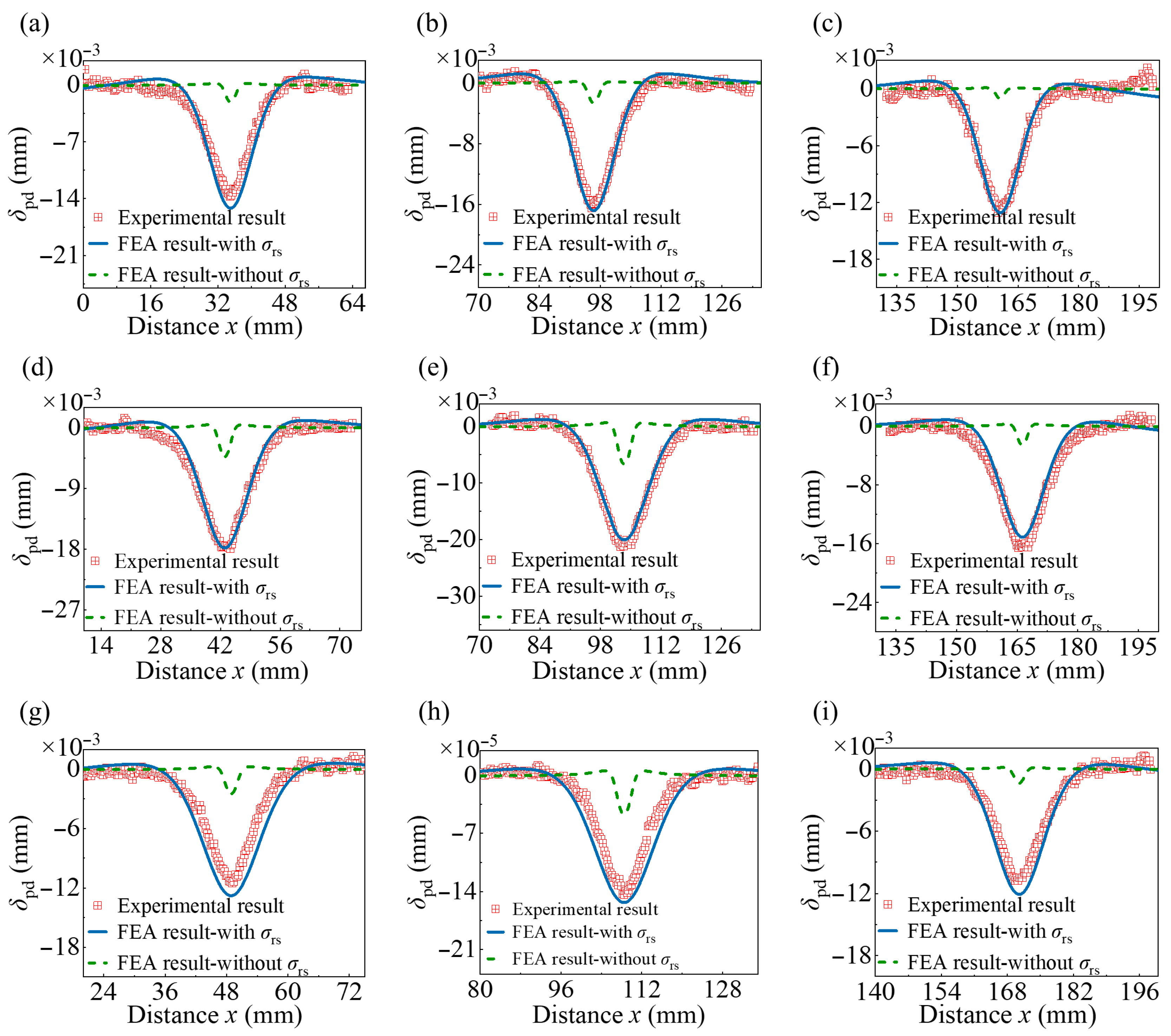
Figure 8 and Figure 9 compare the FE simulation results with the experimental results for the outer and inner rings, respectively. When the residual stress field is incorporated into the model, the numerical simulations results are in good agreement with the experimental measurements, with a maximum error of less than 15%. In contrast, when residual stress is neglected, the predicted values deviate significantly from the experimental results, with a minimum error of more than 50%. The good agreement achieved when residual stress is considered validates the reliability of the proposed FE model. More importantly, it confirms the role of residual stress in determining the elastoplastic contact response of large surface induction-hardened bearings. These findings indicate that residual stress should be considered in the elastoplastic contact analysis of surface induction hardened bearings to improve simulation accuracy.
Figure 8.
Comparison between FE results and experimental results of the outer ring: (a) OR-4-2–4-1; (b) OR-4-2–5-1; (c) OR-4-2–6-1; (d) OR-4-2–4-2; (e) OR-4-2–5-2; (f) OR-4-2–6-2; (g) OR-4-2–4-3; (h) OR-4-2–5-3; (i) OR-4-2–6-3.
Figure 9.
Comparison between FE results and experimental results of the inner ring: (a) IR-5-3–4-1; (b) IR-5-3–5-1; (c) IR-5-3–6-1; (d) IR-5-3–4-2; (e) IR-5-3–5-2; (f) IR-5-3–6-2; (g) IR-5-3–4-3; (h) IR-5-3–5-3; (i) IR-5-3–6-3.
5. Plastic Deformation and Empirical Formula Considering Residual Stress
5.1. Influence of Surface Hardened Depth and Contact Pressure on Elastoplastic Deformation
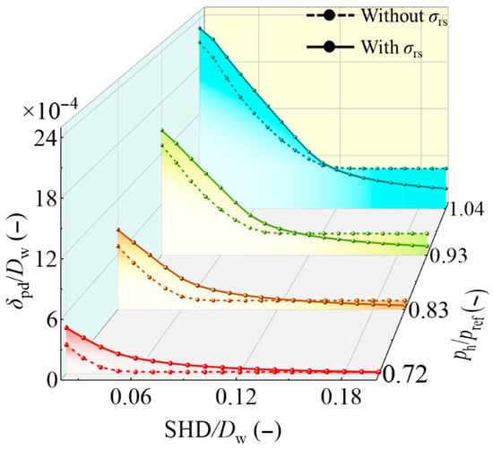
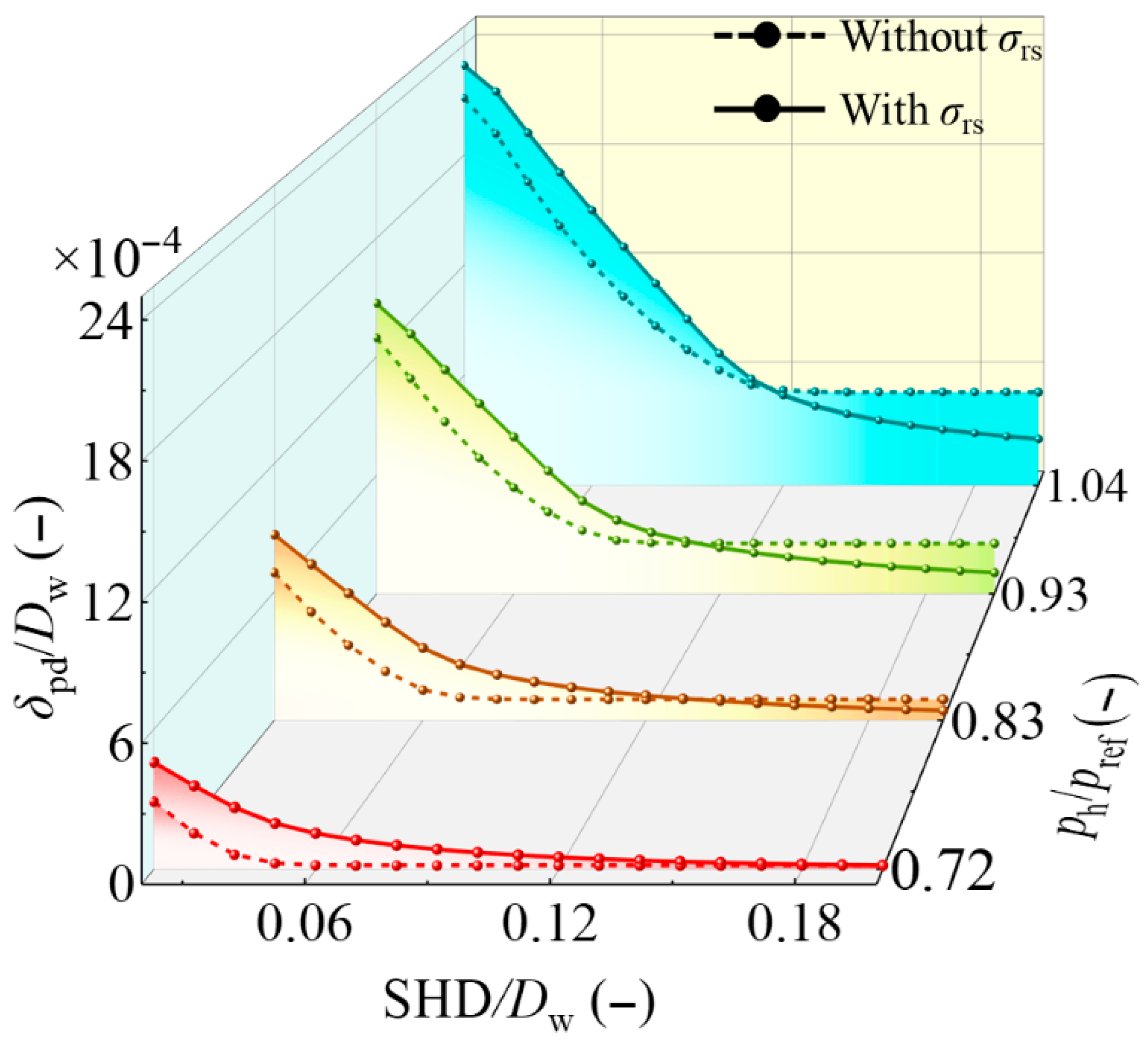
Figure 10 shows the variation in surface plastic deformation with and SHD. In this figure, denotes the equivalent roller diameter, and is the reference contact pressure used for normalization, set to 4 GPa [17]. The results indicate that regardless of whether residual stress is incorporated, surface plastic deformation decreases as the ratio increases. However, the evolution trends differ significantly between the two cases. When residual stress is neglected, the variation in surface plastic deformation with exhibits a clear two-stage characteristic. In the first stage, the deformation decreases rapidly with an increase in . Beyond a specific critical value, a second stage is reached where a further increase in causes almost no change in surface plastic deformation. Furthermore, this critical value increases with the increase of . This behavior is consistent with previous findings [13,14,15,16,17,18,19], which indicate that once SHD is sufficiently large, the plastic deformation of bearings approaches that of through-hardened bearings. In contrast, when residual stress is considered, surface plastic deformation decreases monotonically with increasing , and no obvious plateau is observed. It is also worth noting that the surface plastic deformation curves obtained with and without considering residual stress intersect with each other. At relatively small values of , the predicted plastic deformation is smaller when residual stress is neglected. However, as increases, the deformation predicted with residual stress considered becomes smaller than or comparable to that obtained without residual stress.
Figure 10.
Variation in surface plastic deformation with under different conditions with and without considering residual stress.
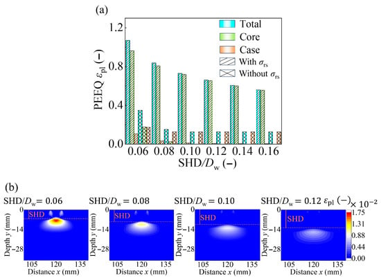
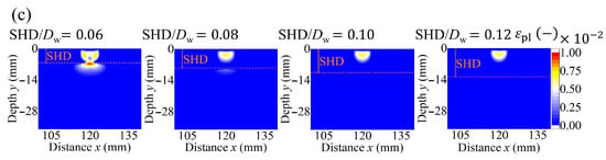
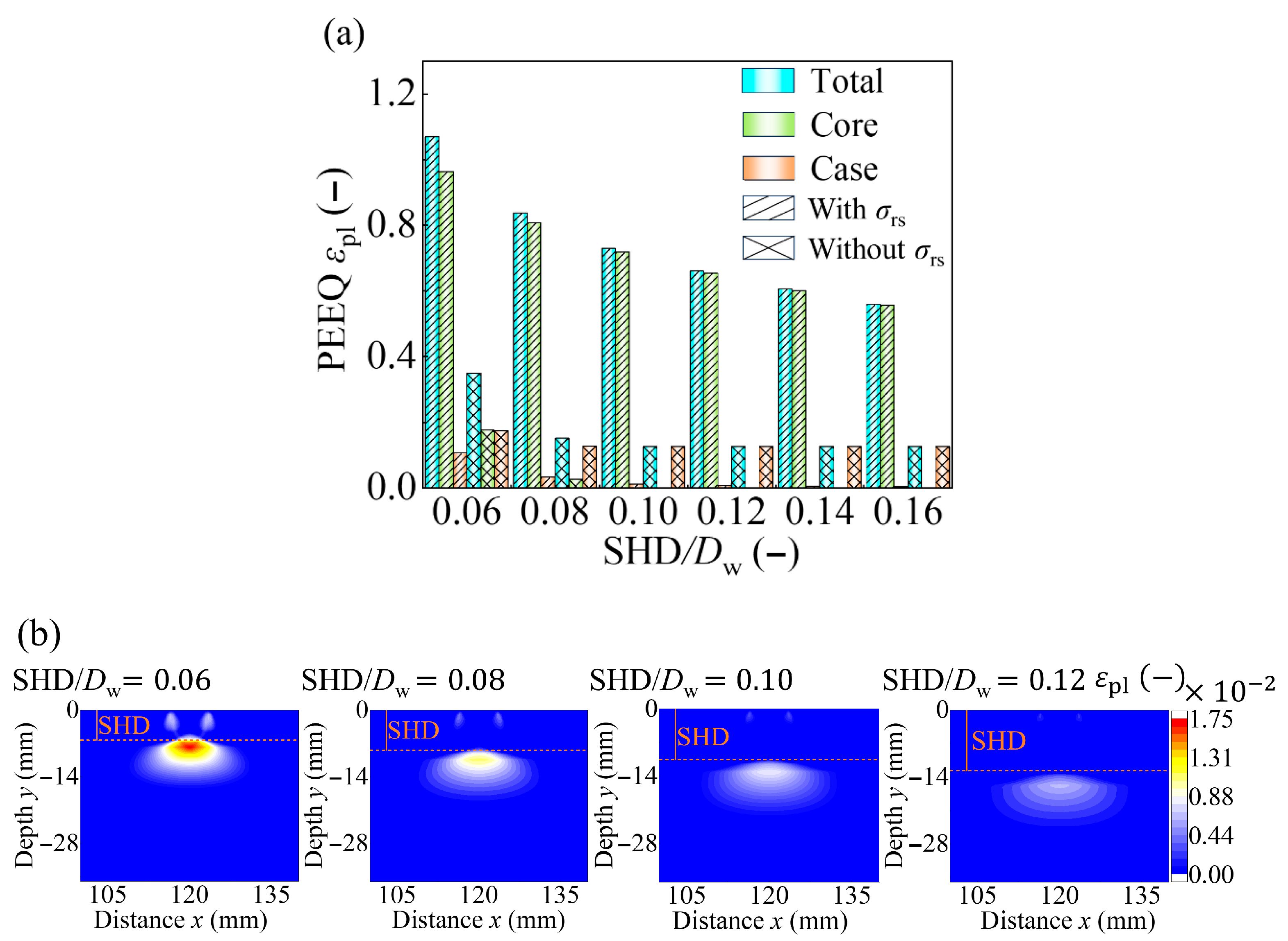
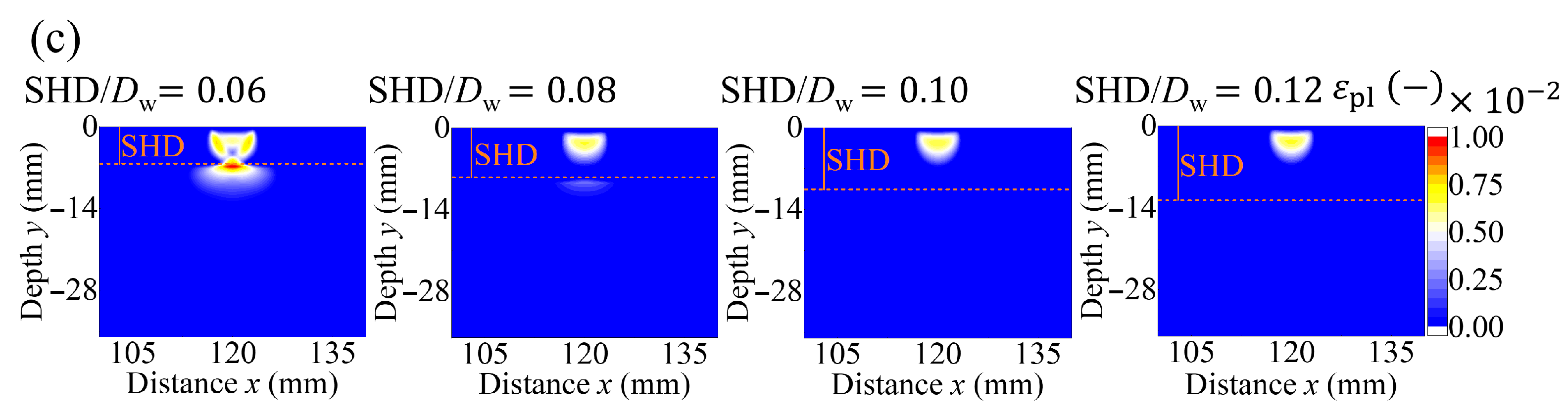
Figure 11 shows the variation in the equivalent plastic strain (PEEQ) in the raceway as a function of at . When residual stress is considered, the total PEEQ decreases gradually with increasing , as shown in Figure 11a. In this case, the plastic deformation is primarily concentrated in the core material region, as illustrated in Figure 11b. In contrast, when residual stress is neglected, the total PEEQ approaches an almost constant value once reaches approximately 0.10 (Figure 11a). At this stage, the plastic strain is fully confined to the hardened layer, as depicted in Figure 11c.
Figure 11.
Variation in equivalent plastic strain with at with and without considering residual stress: (a) Histogram of total equivalent plastic strain versus ; (b) Contour plot of equivalent plastic strain versus with residual stress; (c) Contour plot of equivalent plastic strain versus without residual stress.
5.2. Empirical Formula for Surface Plastic Deformation of Large Surface Induction-Hardened Roller Bearings
Current empirical equations for calculating surface plastic deformation of surface induction-hardened roller bearings have certain limitations. The formula proposed by Li et al. [17] did not include a yield criterion and thus predicts non-zero plastic deformation even under low loads where no yielding should occur. Lai et al. [18] predicted surface plastic deformation by linearly superposing the plastic contributions from the hardened layer and the core material, with the respective contributions assigned based on yield conditions. However, their yield criterion assumes a constant maximum von Mises stress factor (0.56 for line contact), which becomes questionable once plasticity initiates and the stress field is redistributed. Furthermore, the FE models used in these studies did not consider residual stresses. As shown in this study, the residual stress plays a non-negligible role on surface plastic deformation. Accordingly, based on an extensive series of elastoplastic contact simulations that incorporate residual stress, this study gives a formula for surface plastic deformation that is specifically applicable to large-size surface induction-hardened roller bearings.
The contact pressure at the midpoint of the roller generatrix (corresponding to OR-4-2–5-2 in Table 2 and IR-5-3–5-2 in Table 3) is the highest among the measured positions and thus represents the most critical position for potential failure. Accordingly, the geometric parameters used in subsequent numerical simulations were selected to match those of OR-4-2–5-2 and IR-5-3–5-2. Furthermore, to better simulate the actual service condition of the intact bearing, boundary condition 1 (Figure 6a), which maintains circumferential continuity, was used in the subsequent analyses.
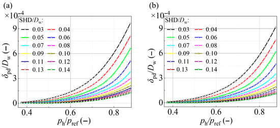
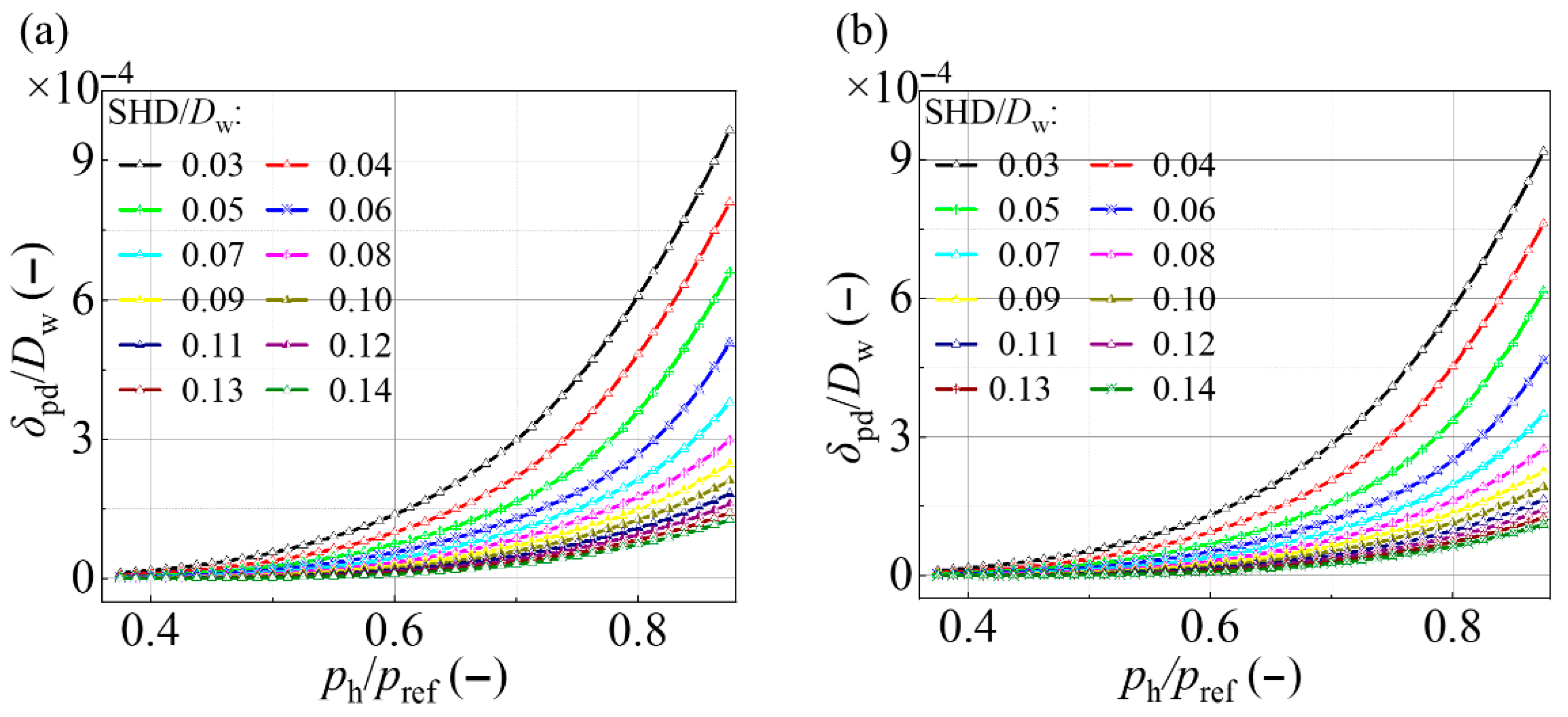
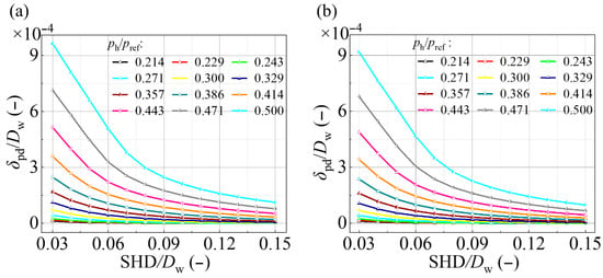
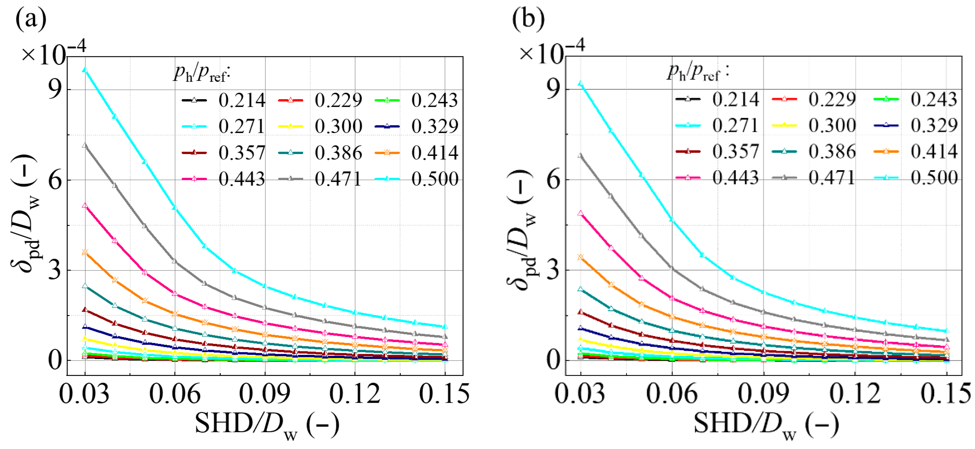
Figure 12 and Figure 13 show the dependence of surface plastic deformation on and , respectively. The results show that surface plastic deformation increases nonlinearly with increasing , while it decreases nonlinearly as increases. Based on these trends, the surface plastic deformation is expressed as an exponential function with the natural constant as the base, with and as the primary governing variables:
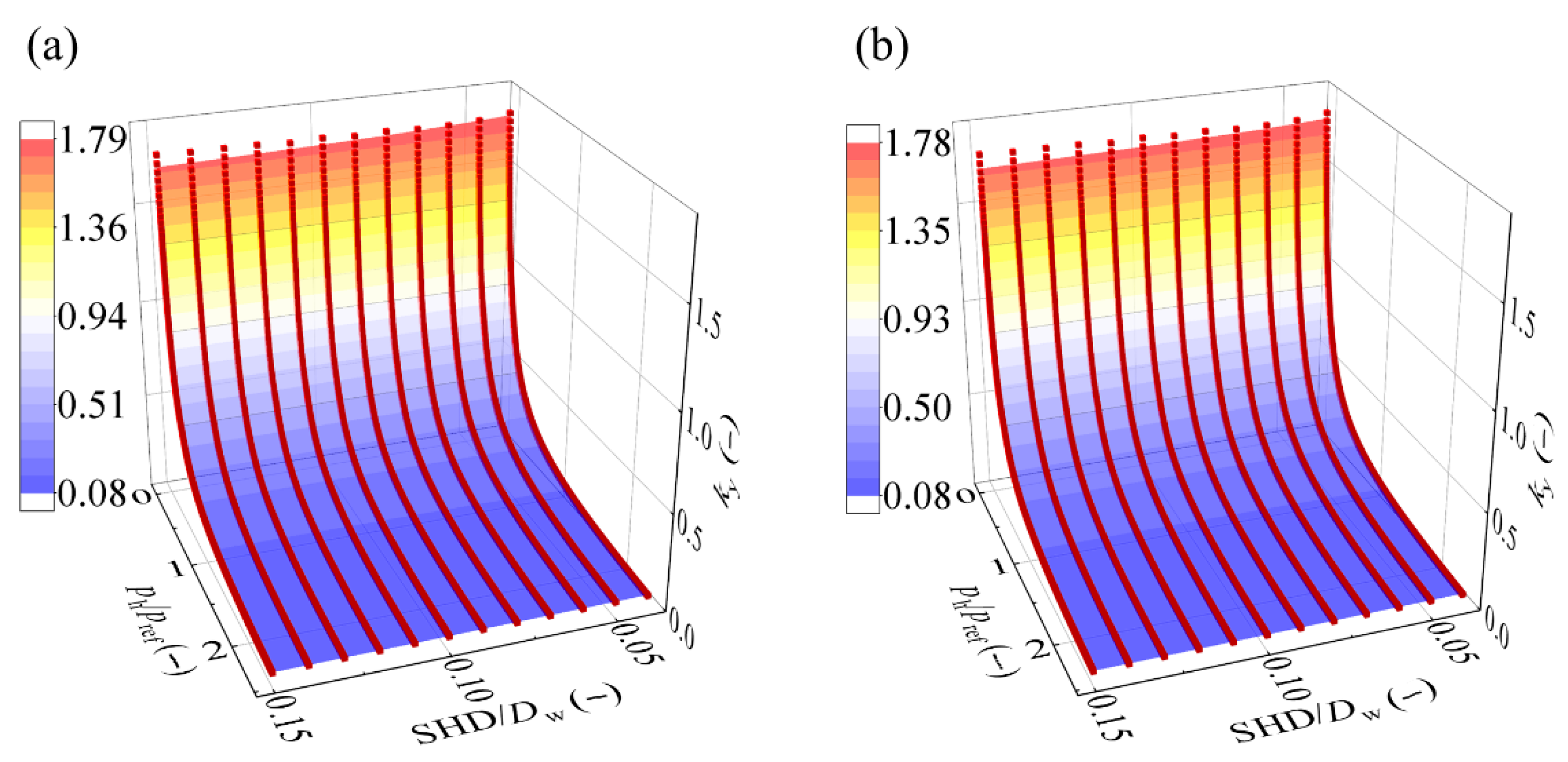
where , , , and are fitting parameters determined from the surface plastic deformation data obtained via FE simulations. The proposed formulation further incorporates a yield criterion, where ⟨ ⟩ denotes the Macaulay bracket. The term represents the dimensionless von Mises stress calculated at the position of maximum residual tensile stress in the core material. Its mathematical expression is expressed as follows:
where , , , and are constants determined by fitting the von Mises stress values obtained from FE simulations.
Figure 12.
Variation in surface plastic deformation with under different : (a) outer ring; (b) inner ring.
Figure 13.
Variation in surface plastic deformation with under different : (a) outer ring; (b) inner ring.
For Equation (6), regression analysis was conducted with FE sampling at intervals of and to ensure sufficient fitting accuracy. The coefficient of determination for both the inner and outer rings is up to 0.9994, indicating an excellent correlation between the fitted expression and the numerical data. A comparison of the fitted results with the FE predictions is shown in Figure 14. The gradient-colored surface corresponds to the values calculated via the fitted formula, while the red scatter points represent the FE results. The close overlap between the two validates the high accuracy of the proposed expression.
Figure 14.
Comparison of dimensionless von Mises stress between FE results and formula fitting results: (a) outer ring; (b) inner ring.
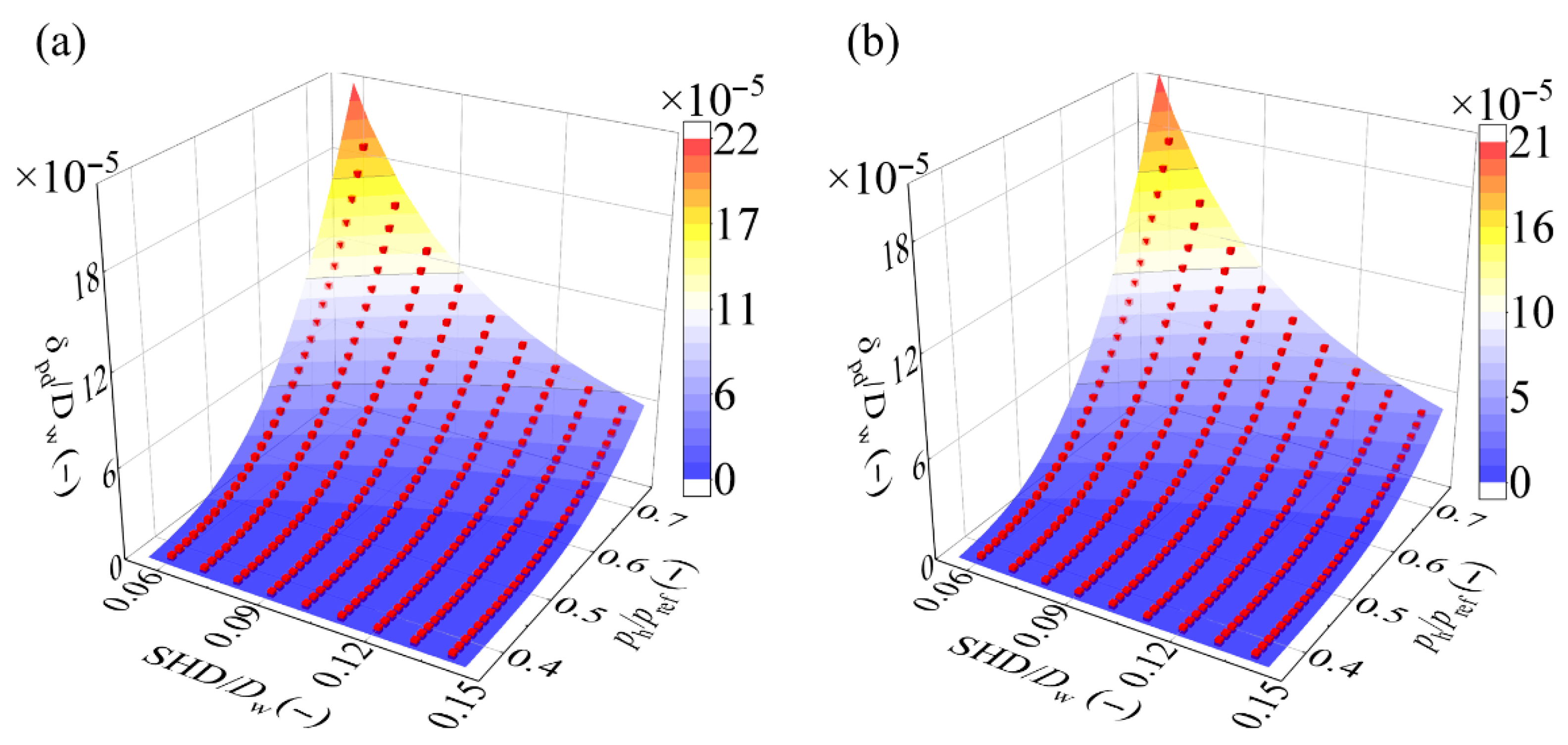
For the regression analysis of the surface plastic deformation expression in Equation (5), FE sampling was performed at increments of and . The coefficient of determination for both the inner and outer rings reached 0.9995, indicating a high fitting accuracy. As illustrated in Figure 15, the FE results are in close agreement with the fitted surface, which further validates the accuracy of the proposed formulas.
Figure 15.
Comparison of surface plastic deformation between FE results and formula fitting results: (a) outer ring; (b) inner ring.
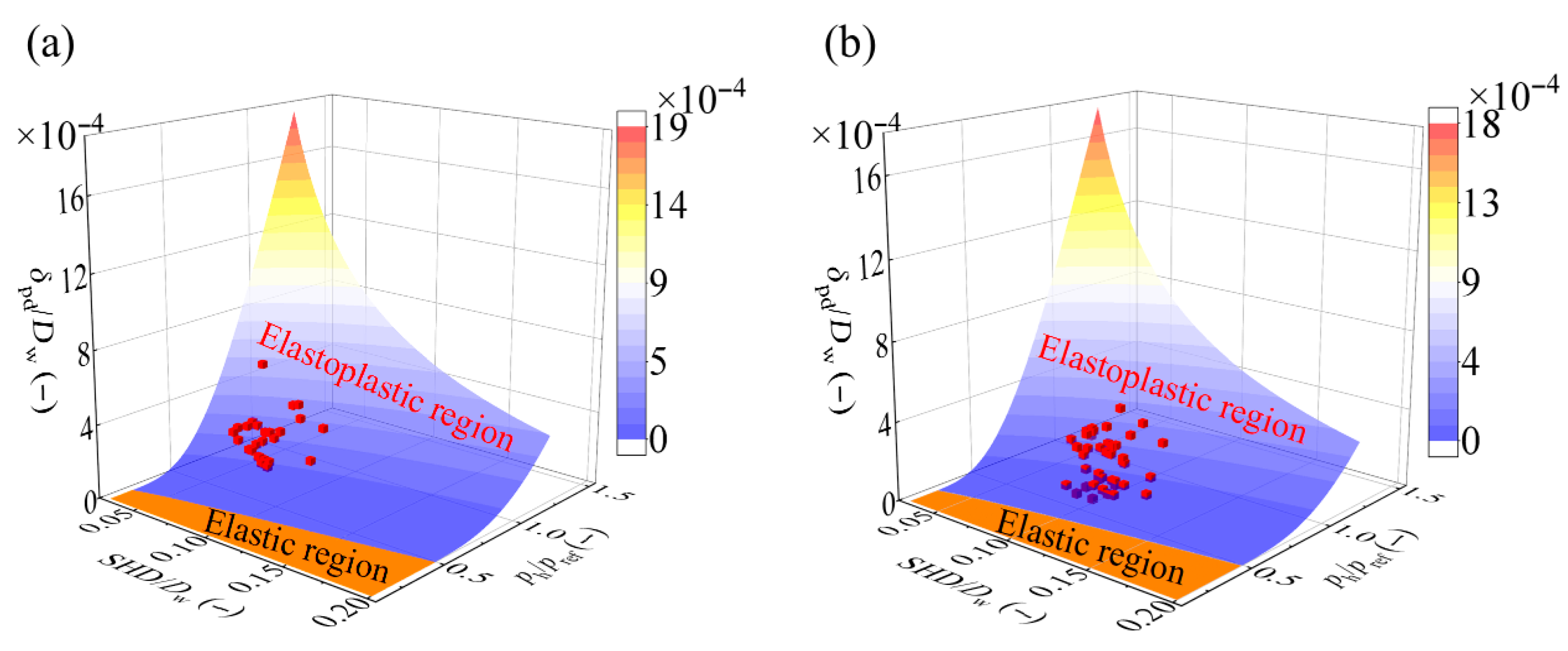
Figure 16 shows a comparison of the surface plastic deformation predicted by the proposed formula with the results obtained from the static compression tests. In this figure, the gradient-colored surface represents the calculated values, while the red dots correspond to the experimental measurements. The orange region indicates purely elastic behavior, while the remaining gradient-colored area corresponds to the elastoplastic regime. In this regime, material yielding initiates, and the surface plastic deformation varies nonlinearly with both contact pressure and SHD. The comparison shows that the deviation between the predicted values from the formula and the experimental measurements is less than 10% in most cases, with only a small number of data points showing deviations close to 15%. Considering the effect of boundary conditions on surface plastic deformation discussed in Section 4.1, the discrepancy in practical engineering applications is expected to be further reduced. Overall, these results prove the validity and predictive capability of the proposed formulation.
Figure 16.
Comparison of surface plastic deformation between formula calculation results and static pressure test results: (a) outer ring; (b) inner ring.
6. Conclusions and Outlook
This study investigates the elastoplastic contact behavior of large-size surface induction-hardened tapered roller main bearings for wind turbines, with a particular focus on the role of residual stress. By comparing the FE simulations with experimental measurements, the crucial role of residual stress on the elastoplastic contact response was evaluated. Based on parametric FE analyses, predictive formulas for surface plastic deformation and material yielding that explicitly incorporates residual stress were given. The main conclusions are summarized as follows:
- (1)
- Elastoplastic contact simulations considering residual stress show significantly improved agreement with the static compression experimental results. This confirms that residual stress should be considered in the elastoplastic contact analysis of large surface induction-hardened roller bearings to enhance simulation accuracy.
- (2)
- Residual stress modifies the initial stress state inside the surface induction-hardened bearing, leading to distinct evolution patterns of surface plastic deformation with respect to contact pressure and SHD, depending on whether residual stress is considered. Consequently, the predicted stress field and plastic deformation behavior of the bearing is affected by the inclusion or omission of residual stress.
- (3)
- Empirical formulas were proposed for both surface plastic deformation and material yielding in surface induction-hardened bearings. The former enables a rapid estimation of the maximum surface plastic deformation, while the latter provides a practical criterion for assessing the onset of material yielding.
The experiments, numerical simulations, and derived formulations in this study are all based on a single roller–raceway contact pair. In future research, the proposed empirical formula could be combined with the global load distribution analysis of the bearing system, considering the interaction between multiple rollers and raceways, thereby extending its application to the assessment of the plastic deformation of every contact position in the entire bearing. Furthermore, both the experimental and numerical investigations in this study were conducted under a single loading–unloading cycle. Subsequent studies will carry out cyclic loading–unloading tests and numerical simulations to further clarify the influence of material strengthening on the evolution of plastic deformation. The effect of different surface induction hardening process parameters (e.g., heating temperature, cooling rate) on residual stress distribution and the plastic deformation behavior will also be investigated to provide a more comprehensive theoretical basis for surface induction hardening process optimization.
Author Contributions
Conceptualization, H.L. and Y.Z.; methodology, Y.Z. and H.L.; software, X.G.; validation, H.L. and Y.Z.; formal analysis, H.L.; investigation, X.G., Y.Z., and W.L.; data curation, X.G.; visualization, X.G.; supervision, F.G., W.L., and H.L.; project administration, X.W. and W.L.; writing—original draft preparation, X.G.; writing—review and editing, all authors. All authors have read and agreed to the published version of the manuscript.
Funding
This research was funded by Chief Scientist Program of Gansu Province (23ZDKA012), Key R&D Program of Shandong Province (2022CXGC020309, 2023CXPT060, 024KJHZ017), Joint Research Fund of Disciplines of LICP-CAS (LHJJ-20240102), and the China Postdoctoral Science Foundation (2025M771396).
Data Availability Statement
The research data will be made available on request.
Conflicts of Interest
The authors declare no conflicts of interest.
Abbreviations
The following abbreviations are used in this manuscript:
| SHD | Surface Hardened Depth |
| FE | Finite Element |
| TRB | Tapered Roller Bearing |
References
- Lee, R.M.; Chen, J.C.; Liu, J.H. Advanced analysis of main bearing failure modes and design optimization in MW-sized wind turbines: A multi-physics coupling theoretical framework. Eng. Fail. Anal. 2025, 181, 109945. [Google Scholar] [CrossRef] [Scilit]
- Peng, H.; Zhang, H.; Shangguan, L.J.; Fan, Y.S. Review of Tribological Failure Analysis and Lubrication Technology Research of Wind Power Bearings. Polymers 2022, 14, 3041. [Google Scholar] [CrossRef] [Scilit] [PubMed]
- Zheng, J.Y.; Ji, J.C.; Yin, S.; Tong, V.C. Internal loads and contact pressure distributions on the main shaft bearing in a modern gearless wind turbine. Tribol. Int. 2020, 141, 105960. [Google Scholar] [CrossRef] [Scilit]
- Cheng, L.J.; Li, W.H.; Li, X.H.; Zhang, M. Advances in surface finishing technology for wind turbine gears: A comprehensive review. Precis. Eng. 2025, 96, 277–303. [Google Scholar] [CrossRef] [Scilit]
- Gretzki, T.; Rodman, D.; Wolf, L.; Dalinger, A.; Krause, C.; Hassel, T.; Bach, F.-W. Economic surface hardening by spray cooling. HTM-J. Heat Treat. Mater. 2013, 66, 290–296. [Google Scholar] [CrossRef] [Scilit]
- Krbata, M.; Eckert, M.; Majerik, J.; Barenri, I. Wear Behaviour of High Strength Tool Steel 90MnCrV8 in Contact with Si3N4. Metals 2020, 10, 756. [Google Scholar] [CrossRef] [Scilit]
- Kohutiar, M.; Krbata, M.; Escherova, J.; Eckert, M.; Mikus, P.; Jus, M.; Polášek, M.; Janík, R.; Dubec, A. The Influence of the Geometry of Movement during the Friction Process on the Change in the Tribological Properties of 30CrNiMo8 Steel in Contact with a G40 Steel Ball. Materials 2024, 17, 127. [Google Scholar] [CrossRef] [Scilit]
- Liu, H.M.; Tang, J.Y.; Liu, C.W.; Liu, Y.S. Understanding the distinction between quenching and carburizing quenching stress field: Evolution mechanism of quenching stress field influenced by carbon content in low-carbon alloy steel. Surf. Coat. Technol. 2024, 489, 131112. [Google Scholar] [CrossRef] [Scilit]
- Harris, T.; Rumbarger, J.H.; Butterfield, C.P. Wind Turbine Design Guideline DG03: Yaw and Pitch Rolling Bearing Life; National Renewable Energy Laboratory: Golden, CO, USA, 2009.
- Pallini, R.A.; Sague, J.E. Computing core-yield limits for case-hardened rolling bearings. ASLE Trans. 1985, 28, 91–96. [Google Scholar] [CrossRef] [Scilit]
- Wang, W.J.; Guo, J.; Liu, Q.Y.; Zhu, M.H. Effect of laser quenching on wear and damage of heavy-haul wheel/rail materials. Proc. Inst. Mech. Eng. J J. Eng. Tribol. 2014, 228, 114–122. [Google Scholar] [CrossRef] [Scilit]
- Li, D.L.; Zhang, M.Q.; Xie, L.C.; Wang, Z.J. Contact yield initiation and its influence on rolling contact fatigue of case-hardened steels. J. Tribol. 2020, 142, 121501. [Google Scholar] [CrossRef] [Scilit]
- Glodež, S.; Potočnik, R.; Flašker, J. Computational model for calculation of static capacity and lifetime of large slewing bearing’s raceway. Mech. Mach. Theory 2012, 47, 16–30. [Google Scholar] [CrossRef] [Scilit]
- Göncz, P.; Potočnik, R.; Glodež, S. Computational model for determination of static load-carrying capacity of three-row roller slewing bearings with arbitrary clearances and predefined raceway deformations. Int. J. Mech. Sci. 2013, 73, 82–92. [Google Scholar] [CrossRef] [Scilit]
- Göncz, P.; Ulbin, M.; Glodež, S. Computational assessment of the allowable static contact loading of a roller-slewing bearing׳s case-hardened raceway. Int. J. Mech. Sci. 2015, 94, 174–184. [Google Scholar] [CrossRef] [Scilit]
- He, P.Y.; Liu, R.; Hong, R.J.; Wang, H. Hardened raceway calculation analysis of a three-row roller slewing bearing. Int. J. Mech. Sci. 2018, 137, 133–144. [Google Scholar] [CrossRef] [Scilit]
- Li, Y.F.; Jia, L. Determination of permissible contact stress of case hardened raceway of roller slewing bearing. Sci. Prog. 2020, 103, 0036850420980609. [Google Scholar] [CrossRef] [Scilit]
- Lai, J.B.; Ovize, P.; Kuijpers, H.; Bacchettto, A. Case depth and static capacity of surface induction-hardened rings. J. ASTM Int. 2009, 6, 1–16. [Google Scholar] [CrossRef] [Scilit]
- Lai, J.B.; Volkmuth, M.; Tanke, J.H. Material Behavior of Case Carburized Bearings Subjected to Standing Contact Loading Conditions. J. ASTM Int. 2024, STP1649-EB, 360–378. [Google Scholar]
- Holmberg, J.; Steuwer, A.; Stormvinter, A.; Kristoffersen, H. Residual stress state in an induction hardened steel bar determined by synchrotron-and neutron diffraction compared to results from lab-XRD. Mater. Sci. Eng. A 2016, 667, 199–207. [Google Scholar] [CrossRef] [Scilit]
- Areitioaurtena, M.; Segurajauregi, U.; Fisk, M.; Cabello, M.J. Numerical and experimental investigation of residual stresses during the induction hardening of 42CrMo4 steel. Eur. J. Mech. A Solids 2022, 96, 104766. [Google Scholar]
- Jászfi, V.; Prevedel, P.; Raninger, P.; Todt, J. Residual stress distribution of a locally and inductively quenched and tempered 50CrMo4 steel analysed by synchrotron transmission techniques. Mater. Des. 2022, 221, 110936. [Google Scholar] [CrossRef] [Scilit]
- Areitioaurtena, M.; Segurajauregi, U.; Fisk, M.; Cabello, M. Numerical and experimental investigation on the residual stresses generated by scanning induction hardening. Procedia CIRP 2022, 108, 827–832. [Google Scholar] [CrossRef] [Scilit]
- Anand, P.; Biswas, J.; Singh, S.S.; Samuel, G.L.; Ramkumar, P.; Edachery, V. Femto-second laser ablated surface-textures in AISI 440C martensitic stainless steel for precision bearings: Hardness, residual stress, lubricant wettability, friction and wear assessment. Opt. Laser Technol. 2025, 183, 112359. [Google Scholar] [CrossRef] [Scilit]
- Lu, S.Q.; Chiu, L.H. Effect of different microstructures on surface residual stress of induction-hardened bearing steel. Metals 2024, 14, 201. [Google Scholar] [CrossRef] [Scilit]
- Lu, S.Q.; Chiu, L.H.; Chang, P.J.; Lin, C.K. Effects of prior heat treatment and induction hardening on the properties of JIS SUJ3 bearing steel. Materials 2025, 18, 1797. [Google Scholar] [CrossRef] [Scilit] [PubMed]
- Lu, S.Q.; Chiu, L.H.; Cheng, H.H. Effects of prior microstructure on the properties of induction-hardened JIS SCM440 steel. Materials 2025, 18, 1045. [Google Scholar] [CrossRef] [Scilit] [PubMed]
- Goñi, A.; Segurajauregi, U.; Areitioaurtena, M.; Esnaola, J.A.; Cabello, M.J. Influence of material composition and quenching severity on numerical prediction of residual stresses and hardness in induction-hardened cylinders. Processes 2024, 12, 2783. [Google Scholar] [CrossRef] [Scilit]
- Aoki, T.; Hayama, M.; Kikuchi, S.; Komotori, J. Peening methods for AISI 4140 steel to induce stable compressive residual stress against cyclic axial loading. Int. J. Fatigue 2025, 201, 109200. [Google Scholar] [CrossRef] [Scilit]
- Zhao, W.D.; Liu, D.X.; Shi, H.L.; Hao, Z.Q.; Zhao, J.W. The effect of surface gradient nanostructure and compressive residual stress on fretting fatigue of A100 ultra-high strength steel by ultrasonic surface rolling process. Int. J. Fatigue 2025, 193, 108775. [Google Scholar] [CrossRef] [Scilit]
- Dechant, S.; Poll, G.; Rüth, L.; Foko, F.F. Einfluss hoher lasten auf das ermüdungslebensdauerverhalten von wälzlagern. VDI-Fachtag. Gestalt.-Berechn.-Einsatz 2023, 2415, 279–300. [Google Scholar]
- Habschied, M.; Graaff, B.D.; Klumpp, A.; Schulze, V. Fertigung und eigenspannungen. HTM J. Heat Treat. Mater. 2015, 70, 111–121. [Google Scholar] [CrossRef] [Scilit]
- Dobberke, D.; Leitner, M.; Wiebesiek, J.; Fröschl, J. Layer approach to model fatigue strength of surface-hardened components. Metals 2024, 14, 754. [Google Scholar] [CrossRef] [Scilit]
- Neslušan, M.; Čížek, J.; Kolařík, K.; Minárik, P.; Čilliková, M.; Oksana Melikhova, O. Monitoring of grinding burn via barkhausen noise emission in case-hardened steel in large-bearing production. J. Mater. Process. Technol. 2017, 240, 104–117. [Google Scholar] [CrossRef] [Scilit]
- Torkamani, H.; Vrček, A.; Larsson, R.; Antti, M.L. Micro-pitting and wear damage characterization of through hardened 100Cr6 and surface induction hardened C56E2 bearing steels. Wear 2022, 492–493, 204218. [Google Scholar] [CrossRef] [Scilit]
- Areitioaurtena, M.; Segurajauregi, U.; Fisk, M.; Cabello, M.J.; Ukar, E. Influence of induction hardening residual stresses on rolling contact fatigue lifetime. Int. J. Fatigue 2022, 159, 106781. [Google Scholar] [CrossRef] [Scilit]
- Londhe, N.; Hyde, S. Influence of different heat treatments on fracture behavior of rolling element bearing steels. Theor. Appl. Fract. Mech. 2024, 131, 104371. [Google Scholar] [CrossRef] [Scilit]
- Dechant, S.; Nordmeyer, H.; Pape, F.; Breidenstein, B. Residual stress engineering for highly loaded rolling-sliding contacts: Finding the sweet spot for maximum durability by hard turning and deep rolling. J. Mater. Process. Technol. 2025, 344, 119027. [Google Scholar] [CrossRef] [Scilit]
- Johnson, K.L. Contact Mechanics; Cambridge University Press: Cambridge, UK, 1987. [Google Scholar]
- Kleemola, H.J.; Nieminen, M.A. On the strain-hardening parameters of metals. Metall. Trans. 1974, 5, 1863–1866. [Google Scholar] [CrossRef] [Scilit]
- Kristoffersen, H.; Vomacka, P. Influence of process parameters for induction hardening on residual stresses. Mater. Des. 2001, 22, 637–644. [Google Scholar] [CrossRef] [Scilit]

Disclaimer/Publisher’s Note: The statements, opinions and data contained in all publications are solely those of the individual author(s) and contributor(s) and not of MDPI and/or the editor(s). MDPI and/or the editor(s) disclaim responsibility for any injury to people or property resulting from any ideas, methods, instructions or products referred to in the content. |
© 2026 by the authors. Licensee MDPI, Basel, Switzerland. This article is an open access article distributed under the terms and conditions of the Creative Commons Attribution (CC BY) license.