


Abstract
The oil collection performance of a planetary oil scoop is important for the lubrication of planetary bearings. This study investigates the effects of operating and structural parameters on oil collection performance and performs multi-objective optimization. A three-dimensional oil–air two-phase flow model was established using the VOF method. The effects of oil inlet flow rate, rotational speed, oil dam height, oil feed hole diameter, oil injection distance, and number of oil feed holes were investigated. An experimental test rig was developed to validate the numerical model. A Kriging surrogate model, Sobol sensitivity analysis, and NSGA-II were then used for multi-objective optimization. The results show that increasing rotational speed, oil dam height, and oil feed hole diameter improve oil collection efficiency, while increasing oil inlet flow rate reduces it. A critical change occurs at an oil injection distance of approximately 25 mm. The maximum deviation between experimental and numerical results is 13.84%. Sensitivity analysis identifies oil feed hole diameter as the main influencing factor. The optimization results show a trade-off between oil collection efficiency and collected oil flow rate, providing a reference for planetary oil scoop design.
1. Introduction
Reliable oil supply is a key issue in high-speed rotating systems. The lubricant in aero-engine bearings not only reduces friction and wear but also removes heat generated by high-speed rolling and sliding motion [1]. Insufficient oil supply can cause overheating and premature bearing failure, while excessive oil supply increases churning loss and pumping power [2]. Therefore, delivering the correct amount of clean oil to the bearing is a central design problem for transmission systems. As engine designs become smaller and faster, direct jet lubrication becomes less suitable [3]. Under-race lubrication offers a compact solution by delivering oil through the bearing race instead of directly spraying the bearing. In this arrangement, an oil scoop rotates with the shaft, captures the oil jet, and guides the captured oil into the bearing through feed holes [4]. Similar oil delivery and cooling problems also appear in hollow-shaft and oil-spray cooling systems of high-speed electric machines [5,6,7,8,9,10,11].
Oil scoops are generally divided into radial and axial types. Radial oil scoops have been studied most extensively. Paleo Cageao et al. experimentally assessed oil scoop capture efficiency in high-speed rotors [12]. Lee et al. investigated factors affecting the behaviour and efficiency of a targeted jet delivering oil to a bearing lubrication system [13]. Korsukova and Morvan used CFD to analyze oil behavior in a scoop and identify factors affecting scoop capture efficiency [14]. Kruisbrink et al. showed that jet splashing can increase scoop capture efficiency under certain conditions [15]. Lyu et al. simulated oil scoop capture efficiency and analyzed the main flow features [16]. Qin et al. designed a curved blade oil scoop and showed that it can improve oil capture efficiency [17]. Zhang et al. analyzed oil capture characteristics and global sensitivity of radial oil scoops with different blade radius differences [18]. Hou et al. optimized oil supply parameters and examined their influence on radial scoop capture characteristics [19]. Jiang et al. studied dual-orifice jet nozzles and optimized their effect on oil capture performance in a radial scoop under-race lubrication system [20]. Jiang et al. experimentally and numerically assessed the impact of a double-orifice oil jet nozzle on radial scoop capture performance [21]. Jiang et al. analyzed internal flow and discharge coefficient characteristics of oil jet nozzles [22]. Despite these efforts, radial oil scoops have some limitations. Their capture performance is sensitive to jet angle, velocity ratio, and splashing behavior [12,14,15]. The radial configuration also needs sufficient space around the shaft for the nozzle and scoop, and its oil path is not always suitable for a compact hollow-shaft structure. When the scoop must be installed at the end of a rotating hollow shaft and supply oil to a planet gear bearing, these limitations become more obvious. Axial oil scoops are therefore a more natural choice for this configuration.
Axial oil scoops have been studied less than radial oil scoops. Lucas proposed a concentric axial oil scoop that can be installed around a rotating shaft [23]. McDonagh proposed a liquid-capturing shaft for collecting oil inside a gas turbine shaft [24]. Qin et al. experimentally studied under-race lubrication of a bearing for a turboshaft aero-engine and reported an oil capture efficiency above 90% [25]. Jiang et al. also studied an axial oil scoop in an aero-engine and analyzed the effects of injection distance [1], rotational speed, oil supply pressure difference, and jet angle on oil capture performance. They proposed a corrected formula for estimating the flow capacity of the feed hole. By contrast, axial oil scoops are especially well-suited for applications including planetary bearing systems. However, few studies focus on an axial oil scoop mounted in the rotating hollow shaft of a planet gear bearing.
For the lubrication of a planet gear bearing in a planetary gear train, the axial oil scoop is mounted on the rotating hollow shaft. The oil jet is sprayed into the scoop, and centrifugal force drives the oil into the bearing through feed holes. The oil–air flow and oil capture performance in this configuration have not been fully clarified. Therefore, this paper studies an axial oil scoop for a planet gear bearing in a planetary gear train. The aims are to reveal the two-phase flow mechanism inside the scoop and to evaluate the oil capture efficiency and captured oil mass flow rate under different operating conditions. The findings are expected to support the design of axial under-race lubrication systems for planetary gear trains.
2. Numerical Modeling
2.1. Problem Definition and Computation Domain
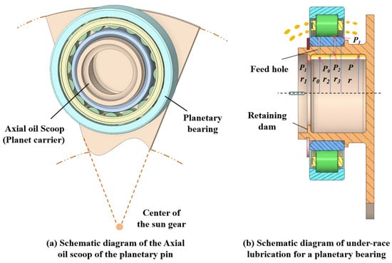
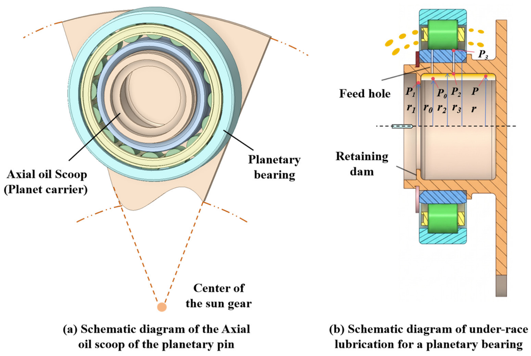
To investigate the oil collection process and collection efficiency of the planetary oil scoop in an aviation planetary gear system, a three-dimensional fluid computational model including the oil scoop, nozzle, and oil supply passage was established. The investigated structure is a typical internal oil supply configuration of a planetary shaft, and its working principle is illustrated in Figure 1. Lubricating oil enters the interior of the planetary oil scoop through the nozzle. During the high-speed rotation of the planetary carrier, the oil moves radially outward under the action of centrifugal force and enters the bearing lubrication chamber through the feed holes distributed on the wall of the oil scoop. Therefore, this process involves complex flow phenomena, including rotation-induced flow, free-surface evolution, and small-scale orifice jet flow.
Figure 1.
Schematic of the planetary oil scoop.
To reduce the computational cost while accurately capturing the key flow characteristics, the computational model was reasonably simplified based on the actual structure. Since this study mainly focuses on the oil collection capability of the oil scoop and the oil capture process at the feed holes, structural details with limited influence on the flow field were neglected, including fasteners, sealing structures, and complex geometric features in non-working regions. Meanwhile, key structures that significantly affect the oil motion, such as the chamfered features inside the oil scoop, were retained.
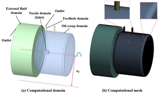
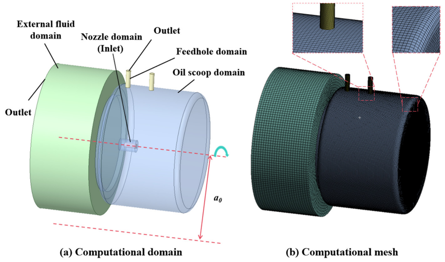
Based on these considerations, the final computational domain consisted of four main regions, as shown in Figure 2a: the nozzle domain, feed hole domain, internal flow domain of the oil scoop, and external flow domain.
Figure 2.
Schematic of the numerical simulation model and mesh.
2.2. Meshes, Cell Zone and Boundary Conditions
The model was meshed using structured hexahedral elements to ensure good mesh quality throughout the computational domain. Local mesh refinement was then applied to critical regions of the oil flow, particularly around the feed holes and the oil scoop wall, to improve the resolution of the oil flow and the oil capture process at the feed holes. After mesh independence verification, as presented in Table 1, the final mesh was selected by balancing computational accuracy and cost, resulting in 1,215,740 elements and 1,262,659 nodes.
Table 1.
The influence of grid quality differences on oil collection efficiency.
For the boundary conditions, the inlet of the nozzle was defined as a velocity inlet, with lubricating oil specified as the inlet fluid to simulate the actual process in which the oil enters the oil scoop through the nozzle. The feed holes on the oil scoop wall and the outlet of the external flow region were both defined as pressure outlets and directly connected to the ambient environment. This configuration was used to simulate the process in which oil enters the bearing lubrication chamber through the oil scoop and excess oil is discharged from the computational domain.
To simulate the rotational motion of the oil scoop as it revolves around the center of the sun gear with the planetary carrier during actual operation, the Multiple Reference Frame (MRF) method was employed to account for the rotational motion of the fluid domain. The oil scoop and the nozzle are rigidly connected to the planetary carrier and therefore rotate together with the carrier. In contrast, the inner ring of the planetary bearing remains stationary relative to the carrier. Consequently, the oil scoop, nozzle, and feed-hole regions do not undergo self-rotation about their own axes. Instead, the entire model rotates counterclockwise about the revolution axis located at the center of the sun gear, with the center of the planetary assembly located 150 mm from this axis.
2.3. Two-Phase Turbulent Flow Model
To capture the oil–air two-phase flow inside the planetary oil scoop, the volume of fluid (VOF) model is employed in combination with the RNG k-ε turbulence model. The VOF model is used to describe the distribution of oil and air and track the evolution of the oil–air interface during the oil collection process. The volume fraction of each phase is determined within each computational cell, where a volume fraction of 1 represents a cell fully occupied by the corresponding phase, while a value of 0 indicates that the phase is absent.
where ρoil represents the density of the oil phase, noa and nao are the mass transfer rates between the two phases within each computational cell, is the net generation or consumption rate of the phase per unit time within a computational cell.
φoil + φair = 1
The oil flow inside the planetary oil scoop is affected by the rotational motion and the complex internal flow structure, which can result in turbulent flow and local flow fluctuations. Therefore, the RNG k-ε model is employed to describe the turbulent characteristics of the flow. The model solves the transport equations for turbulent kinetic energy k and its dissipation rate ε, providing a suitable description of the turbulent flow during the oil collection process.
where νi represents the average velocity during a unit time step, Gν denotes the generation rate of turbulent kinetic energy, μm and μn represent the dynamic viscosity and turbulent viscosity, C1ε and C2ε are model constants.
2.4. Numerical Method
The numerical analysis of the oil collection process inside the planetary oil scoop was performed using Fluent 2022 R1. A transient simulation was conducted based on the implicit VOF method with adaptive time stepping. The governing equations were discretized using the finite volume method. The central difference scheme was applied to the diffusion and pressure terms in the momentum equations, while the second-order upwind scheme was used for the convection terms. The PRESTO! scheme was adopted for pressure interpolation, and the SIMPLE algorithm was used for pressure–velocity coupling.
At the beginning of the simulation, the computational domain was filled with air, and lubricating oil was introduced through the nozzle inlet at a constant velocity. The density of the lubricating oil was set to 920 kg/m3, while that of air was 1.225 kg/m3. The dynamic viscosity of the lubricating oil and air were set to 0.0074 kg/(m·s) and 1.7894 × 10⁻⁵ kg/(m·s), respectively.
The oil collection process does not involve the main heat exchange process. Therefore, temperature effects on the lubricating oil properties are neglected, and the oil properties are assumed constant. The simulation is considered sufficiently converged when the flow rates through all feed holes become stable and the difference between the inlet and outlet oil mass is less than 1%.
3. Simulation Results
This section presents a numerical investigation of the two-phase flow model established for the oil scoop, with particular emphasis on the oil flow and collection process inside the oil scoop. The oil collection efficiency η is considered the primary performance indicator and is calculated as follows:
where Qjet represents the total amount of lubricating oil injected into the oil scoop through the nozzle, and Qcol represents the amount of lubricating oil effectively captured by the oil scoop and ultimately delivered to the bearing lubrication chamber through the feed holes. The oil collection efficiency η represents the proportion of the injected lubricating oil that is effectively collected and delivered to the bearing lubrication chamber. Therefore, it can be used to evaluate the oil collection performance of the oil scoop.
During the rotation of the oil scoop, part of the oil entering the oil scoop is affected by the rotational motion and flows out through the open end of the oil scoop without entering the bearing lubrication chamber through the feed holes, resulting in oil loss. Therefore, improving the oil capture capability of the oil scoop and reducing the amount of oil discharged through the open end are key to improving the oil collection efficiency. Based on this, the effects of different factors on the oil motion and collection efficiency inside the oil scoop are further investigated in this section, and their effects on the oil collection performance are discussed.
3.1. Oil Inlet Flow Rate
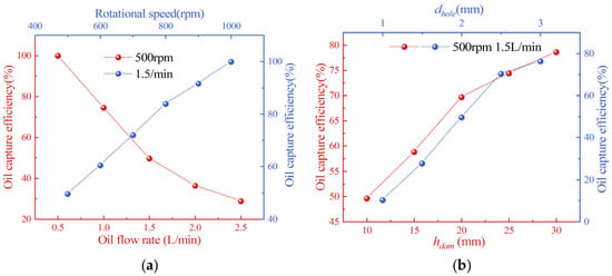
To investigate the effects of different oil flow rates on the oil collection efficiency, numerical simulations were conducted at a rotational speed of 500 rpm, an oil dam height of 10 mm, an oil feed hole diameter of 2 mm, and a jet distance of 25 mm. Figure 3a shows the variation in oil collection efficiency under different oil flow rates. It can be observed that the oil collection efficiency gradually decreases with an increasing oil flow rate. Notably, increasing the oil flow rate does not significantly increase the amount of lubricating oil effectively captured by the oil scoop, which remains at a relatively similar level. In contrast, the amount of oil discharged through the open end of the oil scoop gradually increases.
Figure 3.
Variation in oil collection efficiency under different influencing factors: (a) Effect of operating conditions on oil collection efficiency. (b) Effect of geometric dimensions on oil collection efficiency.
For the feed holes, the flow rate is mainly determined by the pressure difference across the feed holes and can be calculated as follows:
where ΔP denotes the pressure difference across the two ends of the feed hole. Assuming that the oil level inside the oil scoop has reached a steady state, the pressure P at a given location can be decomposed into the following components [1]:
where Pair, Phyd, and Pcen denote the air pressure, hydrostatic pressure, and centrifugal pressure components inside the oil scoop, respectively, and p′ denotes the pressure inside the bearing chamber.
As shown in Figure 2b, ΔP is defined as the pressure difference between the end of the feed hole and the free surface of the oil. It can be calculated as follows:
When the free-surface radius r0 reaches its maximum value (r0 = r1), the pressure difference reaches its maximum value.
Increasing the oil flow rate does not change ΔP across the feed holes. When the rotational speed and oil dam height remain unchanged, the amount of lubricating oil collected through the feed holes remains nearly constant. Therefore, once the pressure difference reaches its maximum value, a further increase in the oil flow rate only increases the amount of oil lost through the open end of the oil scoop, resulting in a decrease in oil collection efficiency.
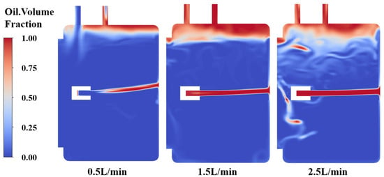
It should be noted that the case with an oil flow rate of 0.5 L/min exhibits a different variation trend (Figure 4). At this relatively low oil flow rate, the liquid level inside the oil scoop has not yet reached the maximum height limited by the oil dam. Therefore, the liquid level varies with the oil flow rate, which in turn affects the pressure difference across the feed holes and the lubricating oil flow rate through the feed holes. Consequently, the effective oil collection rate under this condition differs from that under the higher oil flow rate conditions.
Figure 4.
Two-phase flow distribution in the oil scoop under different Qjet.
3.2. Rotational Speed
At an oil flow rate of 1.5 L/min, the effect of rotational speed on the oil collection efficiency was further investigated, and the numerical results are presented in Figure 3a. As shown, the oil collection efficiency gradually increases with an increasing rotational speed, indicating that a higher rotational speed is beneficial for the effective capture of lubricating oil by the oil scoop.
An increase in rotational speed increases the centrifugal pressure component, thereby increasing ΔP across the feed holes. The increased pressure difference enhances the lubricating oil flow rate captured through the feed holes, resulting in an increase in oil collection efficiency.
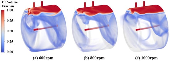
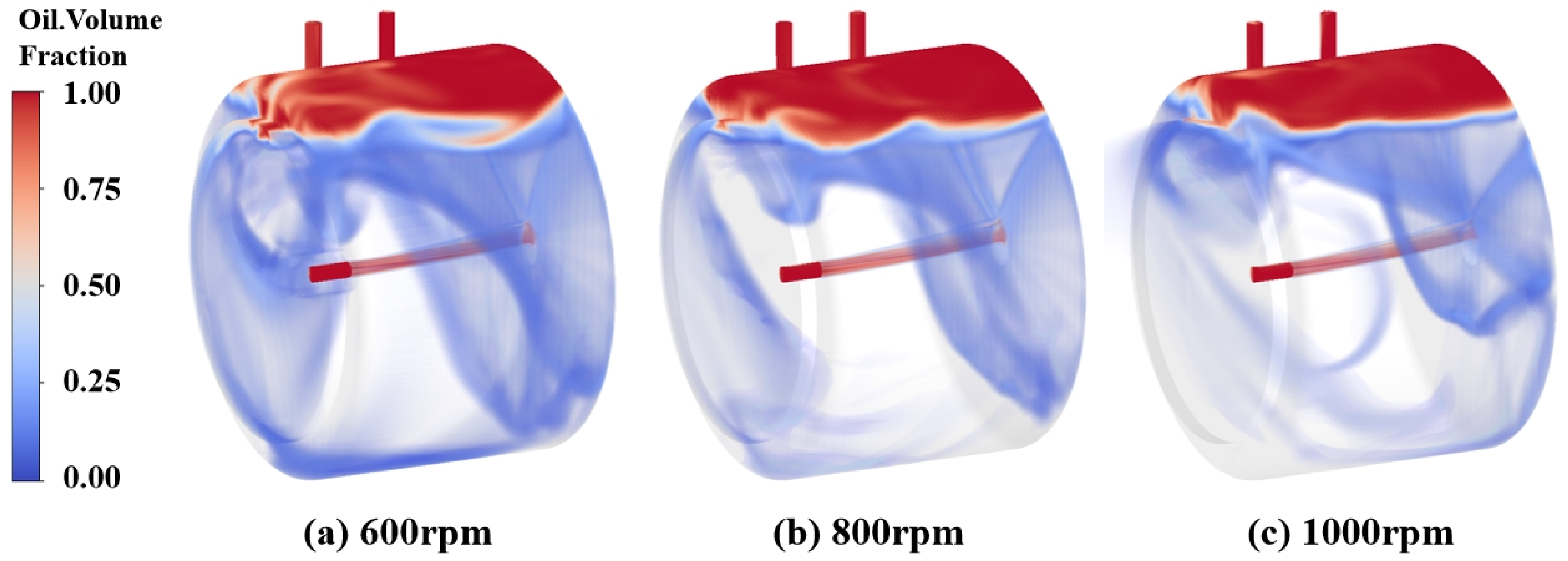
Figure 5 shows the oil distribution inside the oil scoop at different rotational speeds. It can be observed that, as the rotational speed increases, more oil accumulates toward the feed hole side of the oil scoop, forming a relatively stable liquid surface near the feed holes. As the oil accumulation in this region increases, the pressure at the feed holes correspondingly increases, promoting more lubricating oil to enter the bearing lubrication chamber through the feed holes. Therefore, the variation in oil distribution shown in Figure 5 provides a clear explanation of the effect of rotational speed on oil collection efficiency.
Figure 5.
Two-phase flow distribution in the oil scoop under different rotational speeds.
3.3. Height of the Oil Dam
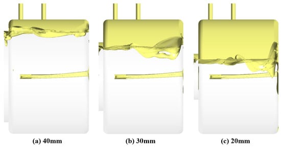
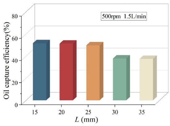
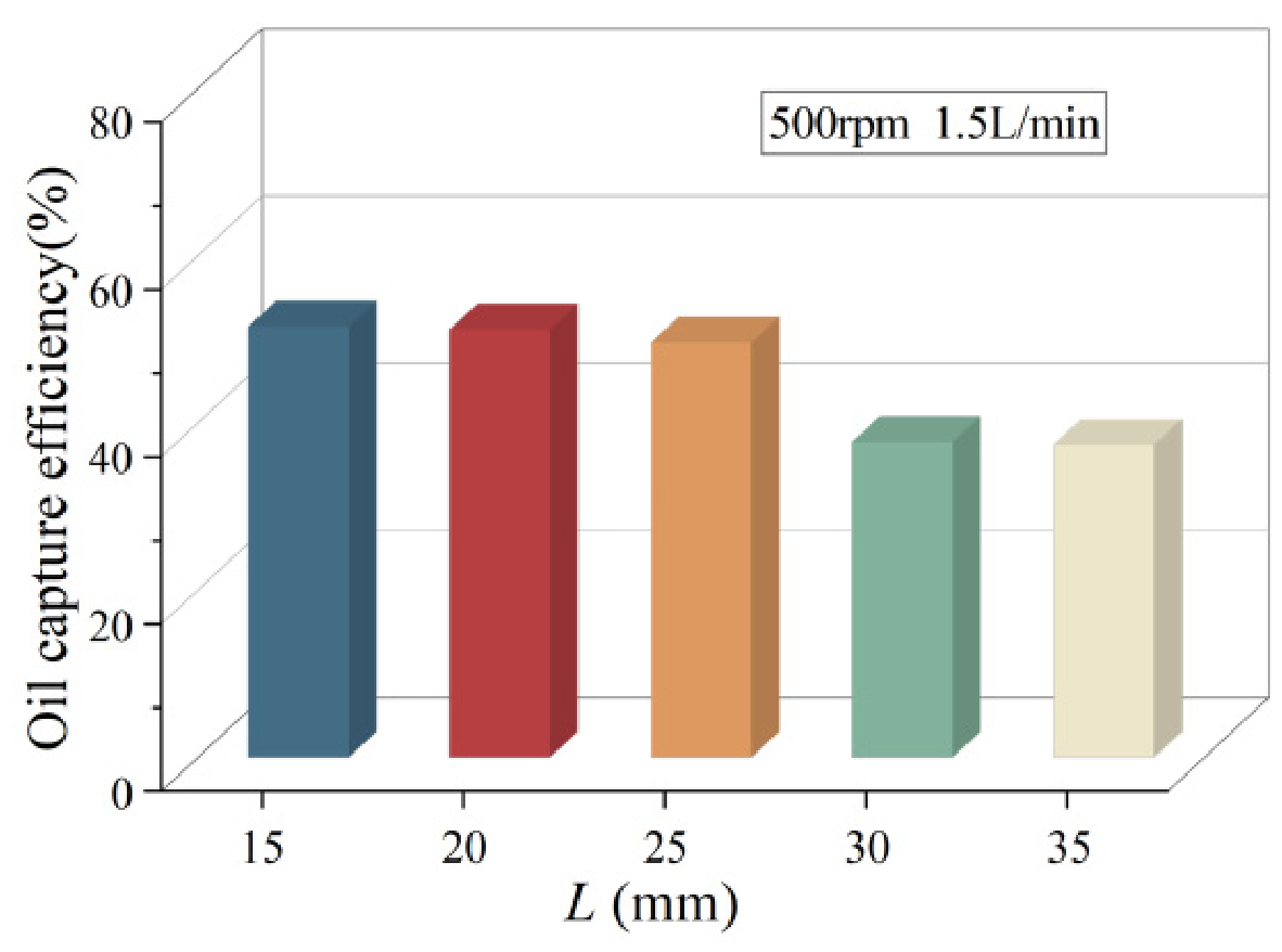
At an oil flow rate of 1.5 L/min and a rotational speed of 500 rpm, the effect of different oil dam heights on the oil collection efficiency was further investigated. The numerical results are presented in Figure 3b. As shown, the oil collection efficiency gradually increases with an increasing oil dam height, indicating that a higher oil dam enhances the oil collection capability of the oil scoop.
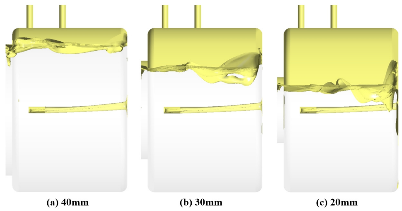
Figure 6 shows the oil distribution inside the oil scoop at different oil dam heights. It can be observed that, as the oil dam height increases, more oil accumulates inside the oil scoop, resulting in an increase in the stable liquid level. Since the feed holes are located on the wall of the oil scoop, the increase in liquid level raises the oil pressure at the feed holes, thereby increasing ΔP across the feed holes. According to the orifice flow relationship discussed above, the increased pressure difference promotes a greater amount of lubricating oil to enter the bearing lubrication chamber through the feed holes. This increases the collected oil flow rate and ultimately improves the oil collection efficiency.
Figure 6.
Liquid level distribution in the oil scoop under different oil dam heights.
Therefore, the oil dam enhances the oil collection performance of the oil scoop by restricting oil discharge through the open end and increasing the stable liquid level inside the oil scoop, thereby strengthening the driving pressure for oil flow through the feed holes.
3.4. Diameter of the Feed Hole
At an oil flow rate of 1.5 L/min and a rotational speed of 500 rpm, the effect of different feed hole diameters on the oil collection efficiency was further investigated. The numerical results are presented in Figure 3b. As shown, the oil collection efficiency gradually increases with an increasing feed hole diameter, indicating that a larger feed hole size is beneficial for improving the effective oil collection capability of the oil scoop.
According to the orifice flow relationship discussed above, the lubricating oil flow rate through the feed holes depends not only on the pressure difference across the feed holes but also on their cross-sectional area. When the pressure difference and other conditions remain essentially unchanged, increasing the feed hole diameter increases its cross-sectional area, thereby increasing the lubricating oil flow rate through the feed hole. Therefore, as the feed hole diameter increases, more lubricating oil can enter the bearing lubrication chamber through the feed holes. The amount of oil effectively captured by the oil scoop consequently increases, resulting in a higher oil collection efficiency.
3.5. Oil Injection Distance
At an oil flow rate of 1.5 L/min and a rotational speed of 500 rpm, the effect of different jet distances on the oil collection efficiency was further investigated. The numerical results are presented in Figure 7. As shown, no clear linear relationship is observed between the oil collection efficiency and the jet distance. Instead, the oil collection efficiency exhibits a relatively distinct stepwise variation around a certain jet distance. When the jet distance exceeds 25 mm, the oil collection efficiency remains approximately 45%, whereas when the jet distance is less than 25 mm, the oil collection efficiency decreases to approximately 25%.
Figure 7.
Effect of jet distance on oil collection efficiency.
The results show that the jet distance exhibits a threshold effect on oil collection performance. As the jet distance increases, the oil jet undergoes greater diffusion and velocity attenuation before reaching the oil scoop, causing more lubricating oil to deviate from the effective collection region. Therefore, a shorter jet distance results in a higher collected oil flow rate. When the jet distance exceeds the threshold, the effect of further increasing the distance becomes relatively limited.
The threshold distance is affected by the jet flow rate, nozzle diameter, and rotational speed. Changes in flow rate and nozzle diameter alter the jet velocity and spreading characteristics, while rotational speed changes the relative motion between the oil jet and the rotating oil scoop. These factors therefore jointly influence the critical distance for effective oil collection.
3.6. Number of Oil Feed Holes
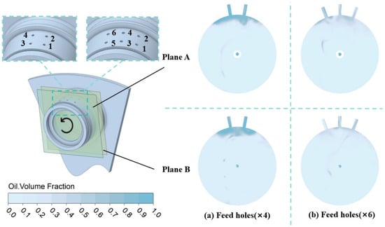
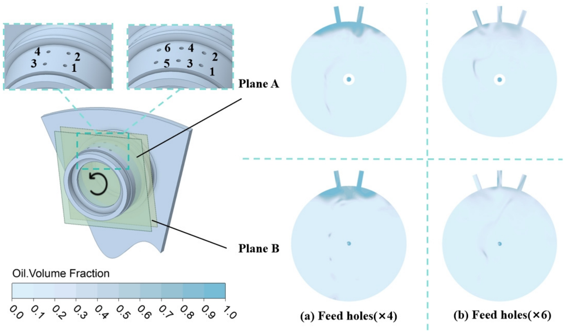
At an oil flow rate of 1.5 L/min and a rotational speed of 500 rpm, the effect of different numbers of feed holes on the oil collection efficiency was further investigated. Numerical simulations were conducted for configurations with 2, 4, and 6 feed holes, and the oil distribution inside the oil scoop is shown in Figure 8. As shown, the liquid level inside the oil scoop gradually decreases with an increasing number of feed holes, indicating that the number of feed holes affects the oil accumulation state inside the oil scoop.
Figure 8.
Two-phase flow distribution under different numbers of oil feed holes.
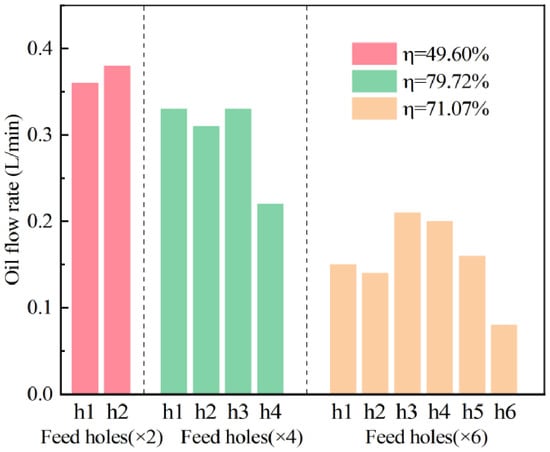
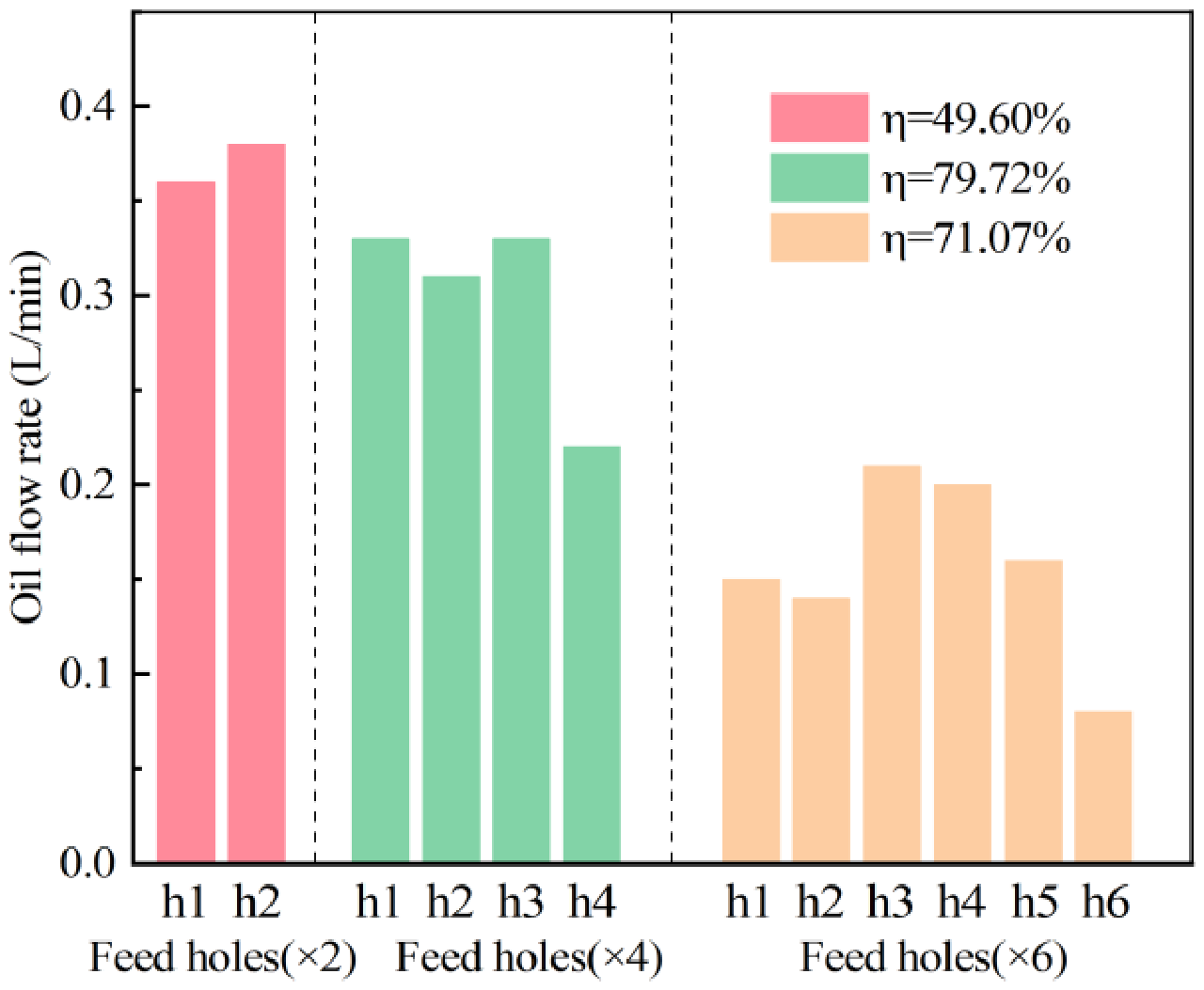
Figure 9 presents the collected oil flow rate and oil collection efficiency for different numbers of feed holes. It can be observed that increasing the number of feed holes does not necessarily improve the oil collection performance. Within the range investigated in this study, the configuration with four feed holes provides relatively favorable oil collection efficiency and collected oil flow rate. Although increasing the number of feed holes increases the total flow area of the feed holes, resulting in an increasing trend in the collected oil flow rate, a larger number of feed holes also accelerates oil discharge from the oil scoop. This reduces the stable liquid level inside the oil scoop and consequently decreases the pressure difference across the feed holes. Therefore, increasing the number of feed holes has both beneficial and adverse effects on the oil collection performance, resulting in a non-monotonic variation in oil collection efficiency.
Figure 9.
Effect of the number of feed holes on Qcol and oil collection efficiency.
Further analysis of the oil capture characteristics of individual feed holes shows that their circumferential positions within the oil scoop also affect their capture capability. In general, feed holes located closer to the radially outer region of the oil scoop and closer to the oil dam exhibit stronger oil capture capability. These regions typically have a higher oil level, resulting in a larger pressure difference across the feed holes and promoting more lubricating oil to enter the bearing lubrication chamber. Therefore, both the number and arrangement of the feed holes affect the oil distribution and pressure field inside the oil scoop, and the relationship between the total flow area of the feed holes and the liquid level should be considered comprehensively.
4. Experimental Setup
This section aims to establish an experimental test rig for investigating the oil collection efficiency of the planetary oil scoop and to experimentally validate the numerical model and simulation results presented above. A physical test system corresponding to the numerical model was developed to reproduce the oil supply and rotational conditions of the planetary oil scoop during actual operation. The amount of lubricating oil effectively captured by the oil scoop was measured under different operating conditions. The experimental results were then compared with the numerical simulation results to verify the accuracy and reliability of the developed two-phase flow model, providing a basis for subsequent optimization of the oil scoop parameters based on the numerical model.
4.1. Experimental Test Rig
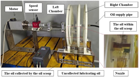
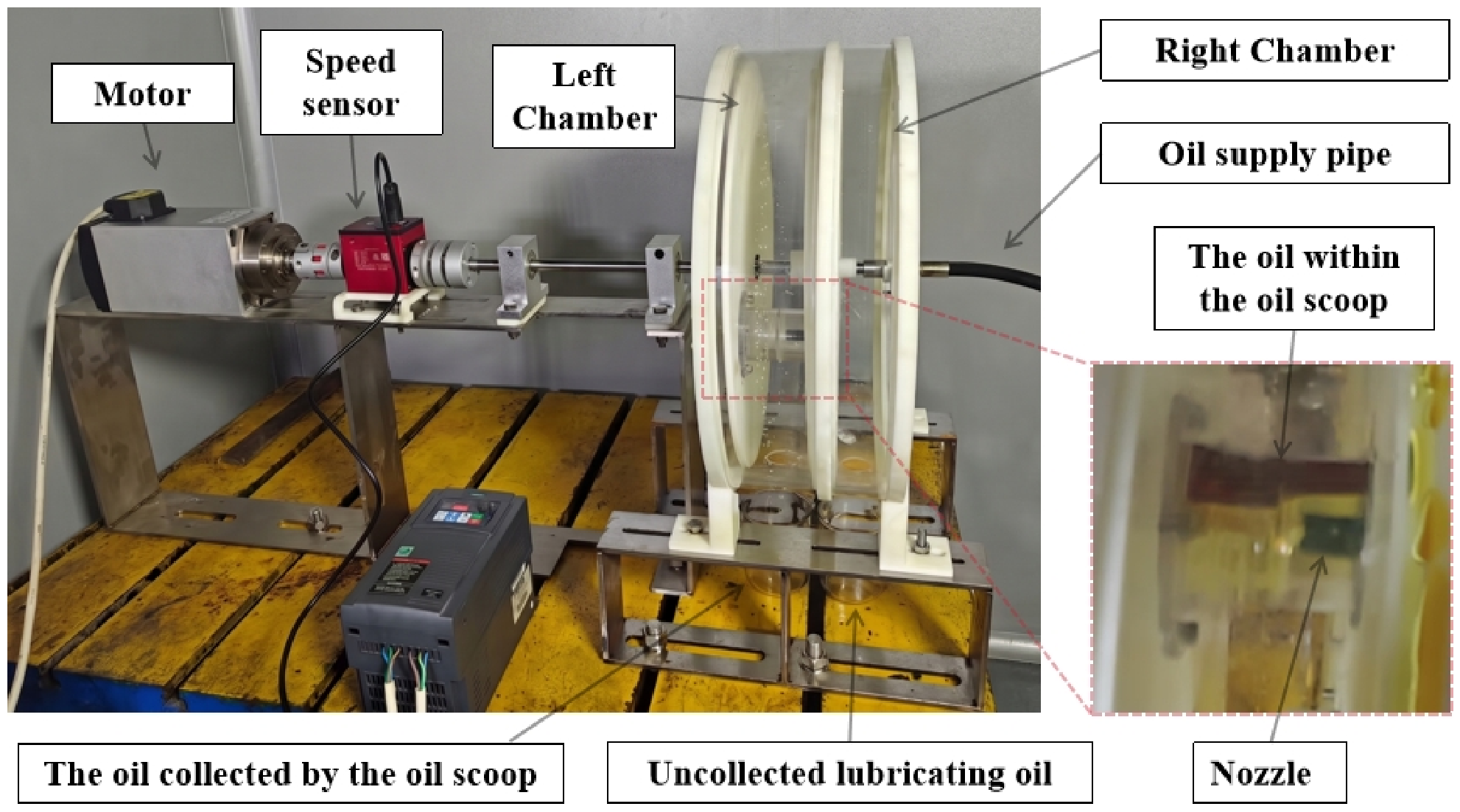
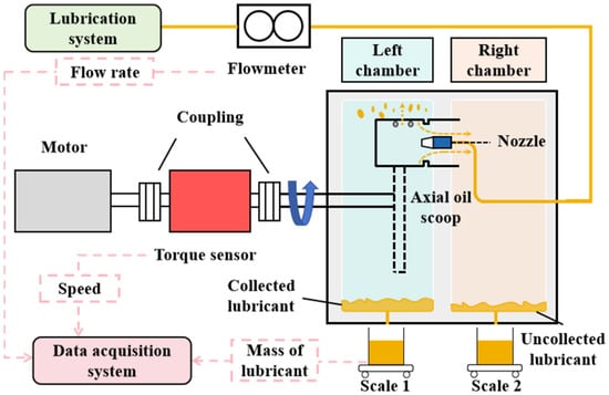
Figure 10 shows a schematic of the experimental test rig for investigating the oil collection efficiency of the planetary oil scoop. A rotating disk was used to simulate the rotational motion of the oil scoop around the center of the sun gear. The planetary oil scoop was mounted on the rotating disk, and different rotational conditions were achieved by controlling the rotational speed of the disk. The distance between the center of the oil scoop and the rotation center was 150 mm, the oil dam height was 10 mm, and the distance between the nozzle outlet and the wall of the oil scoop was 25 mm.
Figure 10.
Experimental test rig for the planetary oil scoop.
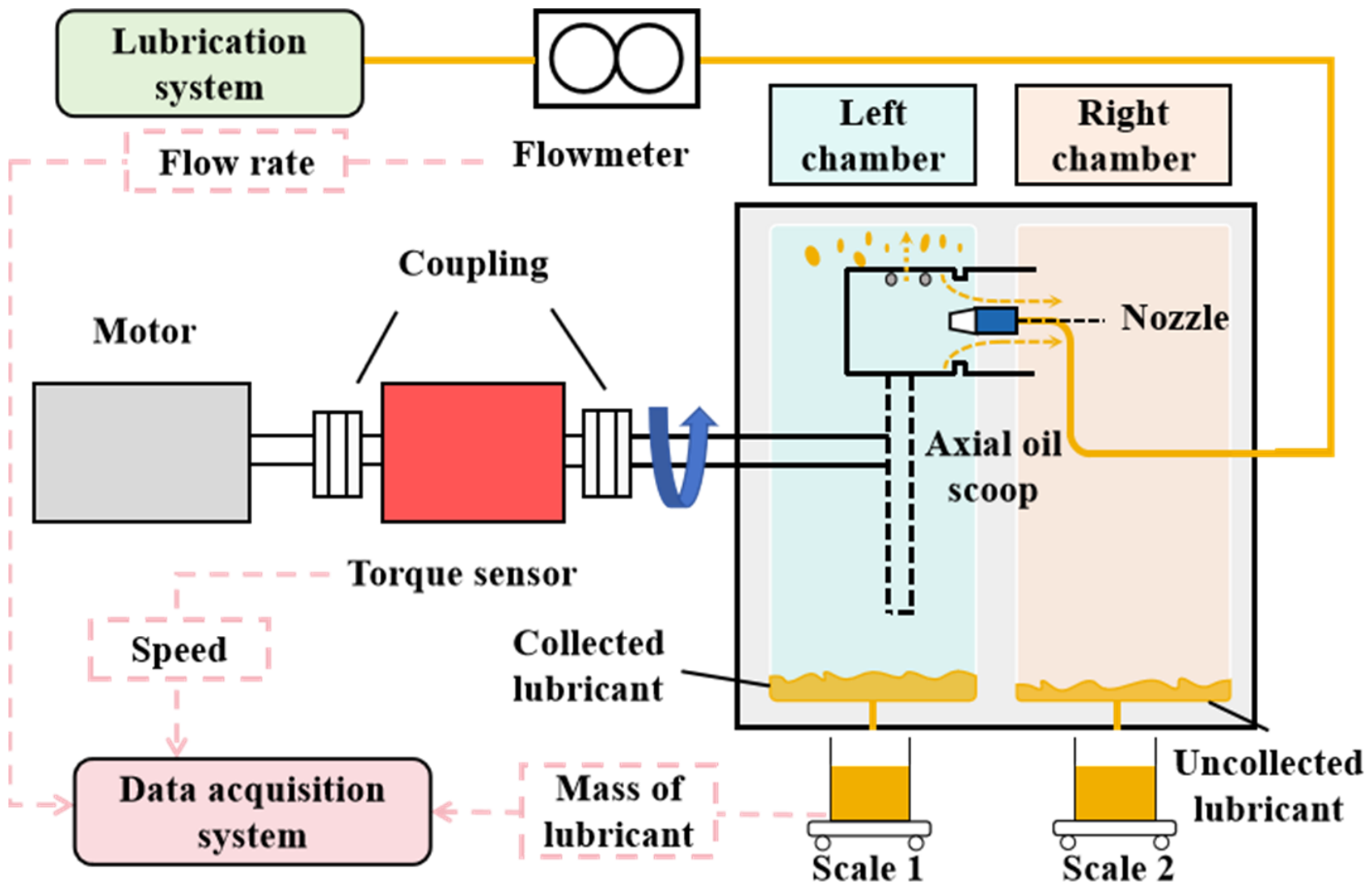
The experimental principle is illustrated in Figure 11. During the experiment, the rotating disk was driven by a motor, and the rotational speed was monitored in real time using a speed sensor with an accuracy of ±0.2% F.S. After the rotating disk reached the preset rotational speed and remained stable, the oil supply system was activated to supply lubricating oil into the oil scoop, while the oil flow rate was recorded using a flow meter with a measurement range of 0.1–20 L/min and an accuracy of ±0.5%.
Figure 11.
Schematic of the experimental setup for the planetary oil scoop.
To separately measure the amount of lubricating oil effectively captured by the oil scoop and the amount discharged through the open end, the test chamber [26,27,28,29] was divided into two independent compartments. The left chamber collected the lubricating oil discharged through the feed holes of the oil scoop, corresponding to the amount of oil effectively captured and discharged by the oil scoop. The right chamber collected the lubricating oil discharged through the open end of the oil scoop, corresponding to the oil that was not effectively captured by the oil scoop.
4.2. Experimental Test Method
In the experimental setup, the oil collected in the left and right chambers was weighed using an electronic balance. The measured oil masses in the two chambers correspond to mcol and mun−col, respectively. The total mass of lubricating oil supplied to the experimental system, mjet, was determined from the measured volumetric flow rate using the flow meter. The oil collection efficiency was calculated as:
At the beginning of each test, the motor was first started, and the rotational speed was monitored until it reached and remained stable at the target operating condition. A predetermined amount of lubricating oil was then supplied to the oil scoop at the preset flow rate. After the lubrication system operated for 10 s, the oil supply was stopped while the motor continued to drive the oil scoop. Due to residual oil on the chamber walls and other parts of the test system, the test was considered complete when the difference between the total mass of oil collected from the two chambers and the supplied oil mass was within 2%. The masses mcol and mun−col were then recorded, and the oil collection efficiency under the corresponding operating condition was calculated.
After each test, the lubricating oil in the collection chambers was drained, and the electronic balance was allowed to return to zero before the next test was started. The oil return process was performed after the measurements to eliminate the influence of fluctuations such as back pressure from the oil return pump on the experimental results. Each operating condition was tested 3–5 times, and the mean value and standard deviation were calculated to reduce the influence of random variations.
4.3. Validation of Numerical Results
The comparison between the experimental and numerical results is presented in Table 2. It can be observed that the experimental results show good agreement with the numerical simulation results in terms of both the qualitative variation trends and quantitative values of the oil collection efficiency. The maximum deviation between the experimental and numerical results is 13.84%, indicating that the developed numerical model can accurately predict the oil collection performance of the oil scoop under different operating conditions.
Table 2.
Comparison of experimental and numerical simulation results.
It should be noted that some uncertainties remain during the experiments. For example, part of the lubricating oil may adhere to the inner wall of the test chamber and other structural surfaces and cannot be completely collected, which may affect the measured oil amount. Therefore, some deviation between the experimental and numerical results is unavoidable. Nevertheless, the experimental results show good overall agreement with the numerical results, providing reasonable validation of the effectiveness of the developed two-phase flow numerical model. This provides a reliable basis for subsequent analysis of the effects of oil scoop parameters and multi-objective optimization based on the numerical model.
5. Multi-Objective Optimization
The preceding simulation results indicate that several factors, including oil flow rate, rotational speed, oil dam height, feed hole diameter, jet distance, and number of feed holes, have different effects on the oil collection performance of the oil scoop. Meanwhile, a higher oil collection efficiency does not necessarily indicate that more lubricating oil can be supplied to the bearing. For example, under a relatively low oil flow rate, the oil scoop may exhibit a higher oil collection efficiency, while the actual amount of oil entering the bearing lubrication chamber remains limited. Therefore, using oil collection efficiency alone as the evaluation criterion cannot fully reflect the oil supply performance of the oil scoop.
Based on the numerical model established above, this section performs multi-objective optimization of the structural and operating parameters of the planetary oil scoop by considering both oil collection efficiency and actual oil supply capability [30]. The optimal configuration parameters of the oil scoop are then determined to further improve its oil collection and oil supply performance.
5.1. Multi-Objective Optimization Process
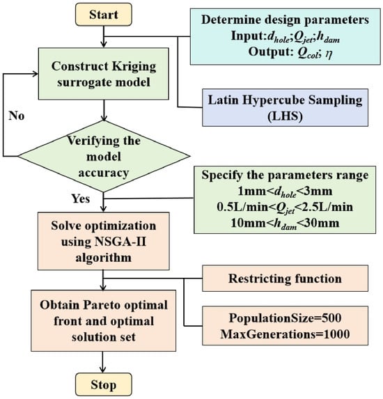
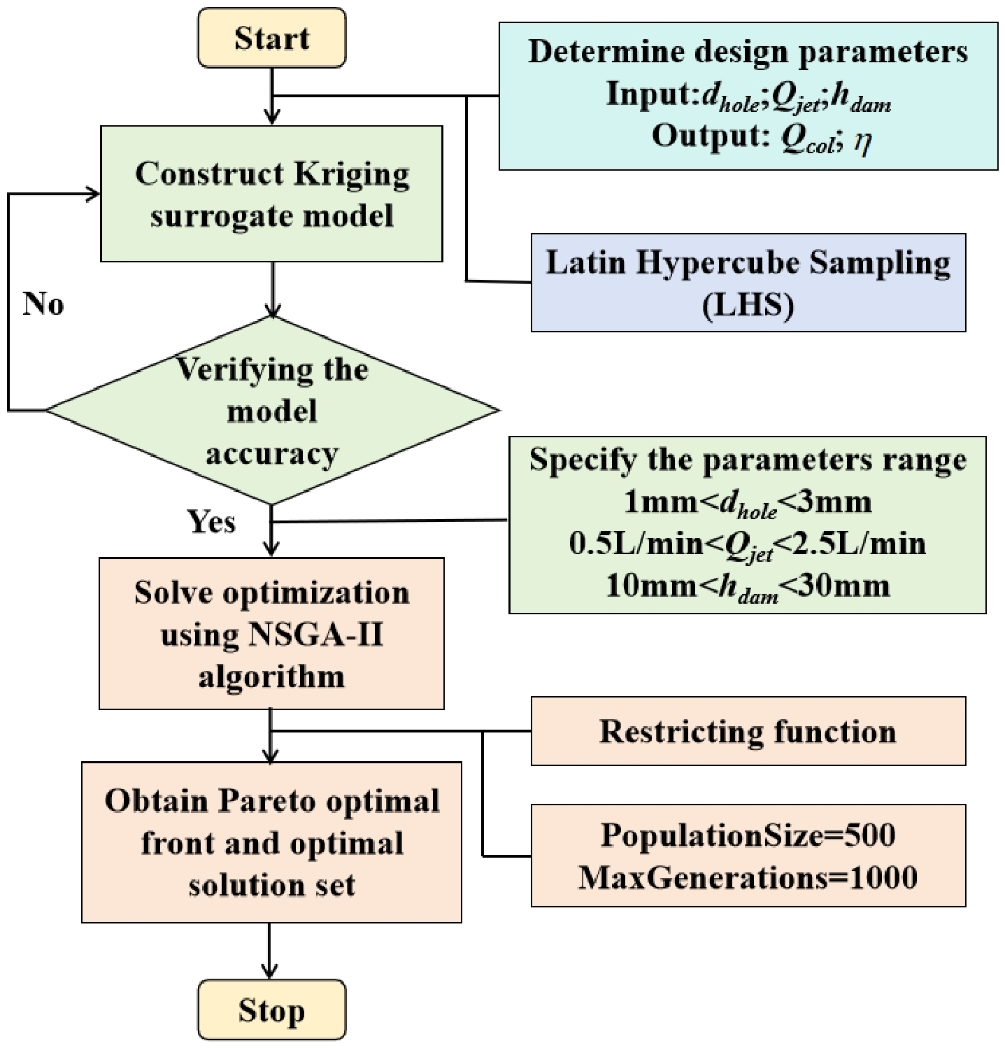
The multi-objective optimization process for the planetary oil scoop is illustrated in Figure 12. First, the optimization objectives and input variables need to be determined. In this study, oil collection efficiency and collected oil flow rate were selected as the two optimization objectives. In the preceding simulation analysis, six variables were considered, including oil flow rate, rotational speed, oil dam height, feed hole diameter, jet distance, and number of feed holes. Since the effect of the number of feed holes on the oil collection performance differs in scale from those of the other variables, the number of feed holes was fixed at two and was not considered as an optimization variable. For the jet distance, a strong nonlinear relationship with the oil collection efficiency was observed, and the preceding results indicated a distinct critical variation near 25 mm. Therefore, the jet distance was fixed at 25 mm and was also excluded from the optimization variables. In addition, the rotational speed is a non-design parameter determined by the actual operating condition. Therefore, the rotational speed was treated as a constraint in the optimization process, and the optimal oil scoop parameters under a specific operating condition were obtained by setting the target rotational speed. Based on these considerations, the oil flow rate, feed hole diameter, and oil dam height were finally selected as the input variables, while the oil collection efficiency and collected oil flow rate were selected as the optimization objectives.
Figure 12.
Multi-objective optimization procedure for the planetary oil scoop.
After determining the optimization variables, the Latin Hypercube Sampling (LHS) method [31] was used to determine the sample points for the initial dataset. CFD simulations were then performed for each sample point to obtain the corresponding oil collection efficiency and collected oil flow rate. A Kriging [32] surrogate model was established using the obtained input variables and output results, and its prediction accuracy was evaluated using validation samples. Only after the surrogate model achieved sufficient prediction accuracy was it used to replace the CFD model in the subsequent optimization process, thereby reducing the computational cost associated with many repeated CFD simulations.
After the surrogate model was validated to meet the required accuracy, the ranges of the optimization variables were further determined. The Non-dominated Sorting Genetic Algorithm II (NSGA-II) was then employed to solve the multi-objective optimization problem [33,34]. The population size was set to 500, and the maximum number of iterations was set to 1000. The non-dominated solutions corresponding to different combinations of input parameters were obtained through the NSGA-II search, forming the Pareto front. Under the target rotational speed, the optimal configuration of the oil scoop was further determined based on the Pareto front, providing the corresponding optimal oil collection efficiency, collected oil flow rate, and input parameters, including oil flow rate, feed hole diameter, and oil dam height.
5.2. Surrogate Model Prediction Accuracy
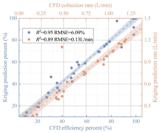
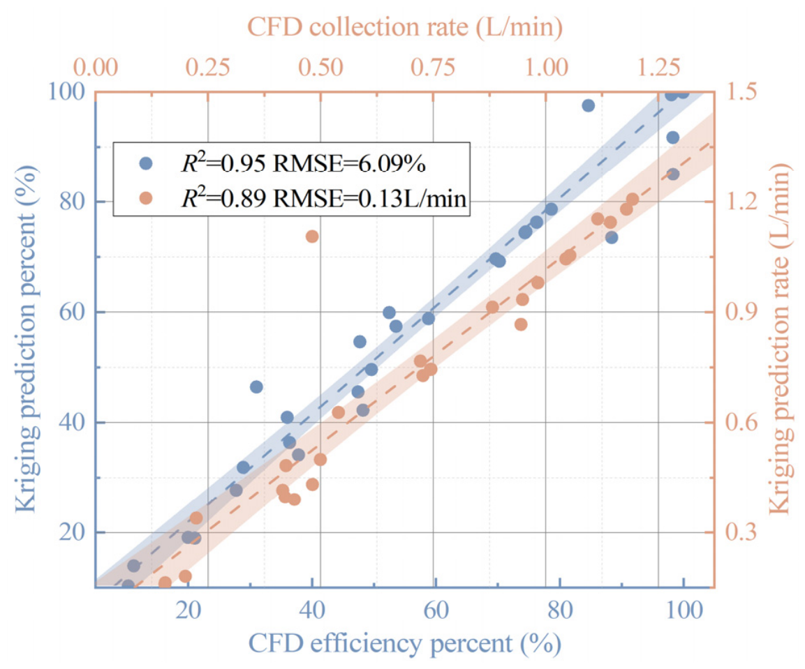
After establishing the Kriging surrogate model, its prediction accuracy was validated, as shown in Figure 13. The results show that the surrogate model provides good prediction performance for both the oil collection efficiency and collected oil flow rate. For the oil collection efficiency, the coefficient of determination (R2) is 0.95, with a Root Mean Square Error (RMSE) of 6.09%. For the collected oil flow rate, R2 is 0.89, and the RMSE is 0.13 L/min. These results indicate that the Kriging surrogate model can effectively describe the relationship between the input variables and the optimization objectives.
Figure 13.
Prediction accuracy of the Kriging surrogate model.
5.3. Global Sensitivity Analysis
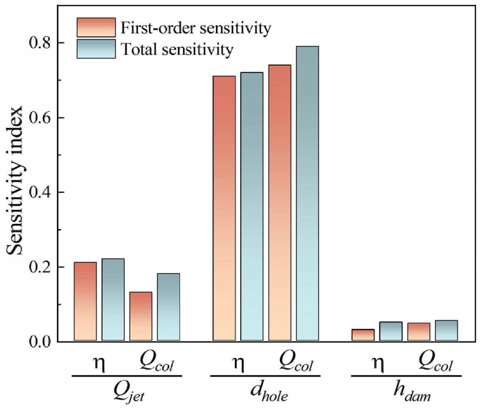
Based on the high prediction accuracy of the Kriging surrogate model, the Sobol method was further employed to analyze the sensitivity between the input variables and optimization objectives, thereby identifying the influence of different input variables on the oil collection efficiency and collected oil flow rate. The first-order and total sensitivity analysis results are shown in Figure 14.
Figure 14.
First-order and total sensitivity analysis.
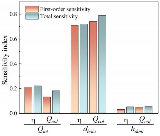
For both oil collection efficiency and collected oil flow rate, the sensitivity of the input variables follows the same order of dhole > Qjet > hdam. Thus, the oil feed hole diameter is the dominant factor affecting both optimization objectives, followed by the oil inlet flow rate and oil dam height.
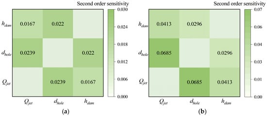
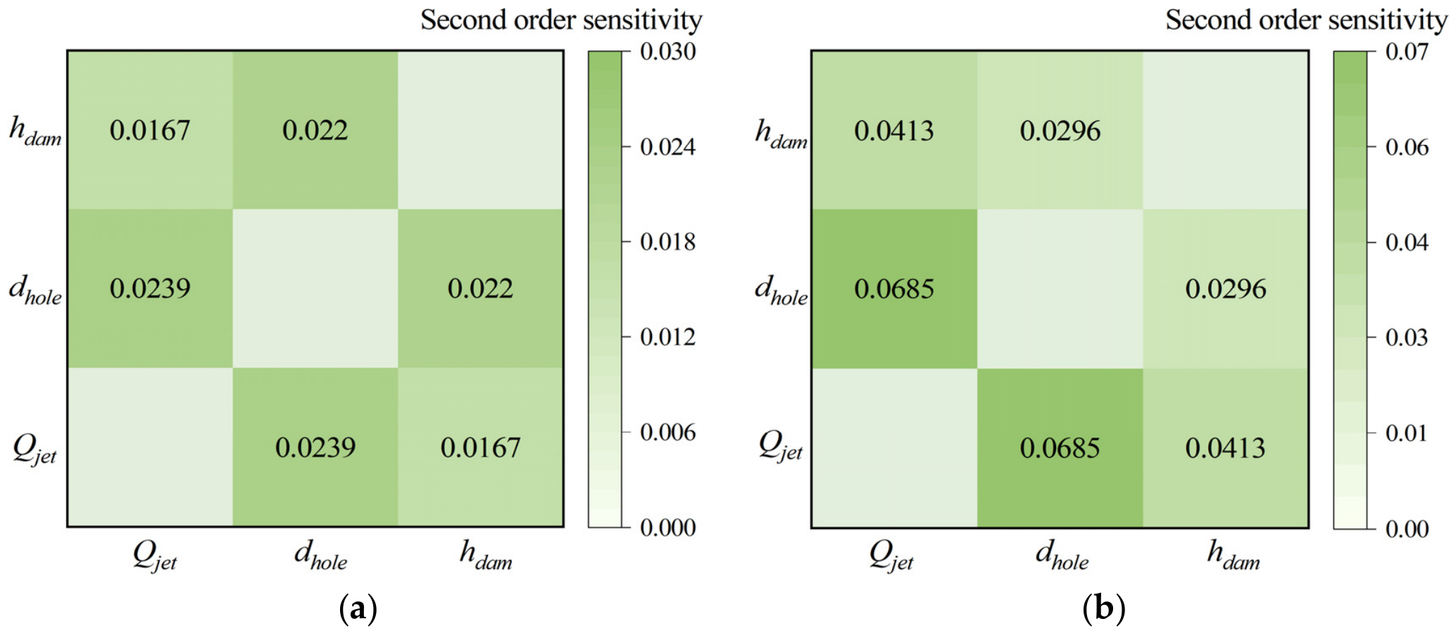
Figure 15 presents the second-order sensitivity analysis results of the input variables, further illustrating the interaction effects between different variable combinations. For both the oil collection efficiency and collected oil flow rate, the combination of oil inlet flow rate and oil feed hole diameter exhibits the highest second-order sensitivity, indicating that their interaction has the most significant influence on both optimization objectives. In comparison, the interactions involving oil dam height show relatively lower sensitivities, suggesting that the coupled effect of oil inlet flow rate and oil feed hole diameter plays a dominant role in determining the optimization results.
Figure 15.
Second-order sensitivity analysis: (a) Efficiency. (b) Collected rate.
Overall, the first-order, total, and second-order sensitivity analysis results show that the oil feed hole diameter has not only a high individual influence but also certain interactions with the other input variables. Therefore, its combined effects with the other design parameters should be considered in the subsequent multi-objective optimization process.
5.4. Multi-Objective Optimization Results
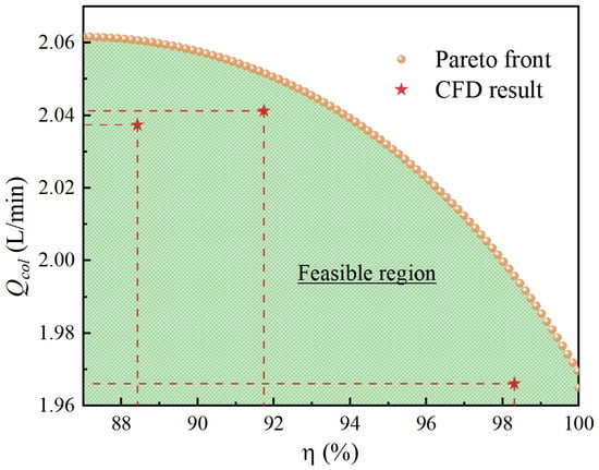
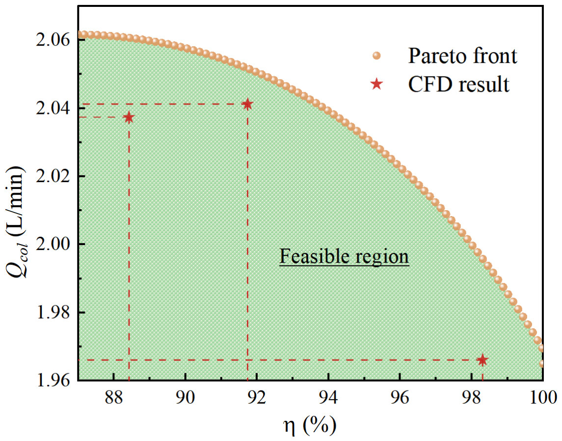
At a rotational speed of 500 rpm, multi-objective optimization of the planetary oil scoop was performed using the NSGA-II method, and the optimization results are shown in Figure 16. It can be seen that the oil collection efficiency and collected oil flow rate exhibit an obvious inverse relationship. As the collected oil flow rate increases, the oil collection efficiency gradually decreases, indicating a trade-off between the two optimization objectives.
Figure 16.
The Pareto frontier calculation results of multi-objective optimization.
The Pareto front provides different optimization solutions that can be selected according to the actual requirements, yielding the corresponding oil collection efficiency and collected oil flow rate. Some representative Pareto-optimal solutions and their corresponding input parameters are presented in Table 3.
Table 3.
Some Pareto frontier solutions and their corresponding input conditions.
6. Conclusions
This study investigated the oil collection performance of a planetary oil scoop through numerical simulation, experimental validation, and multi-objective optimization. The main conclusions are as follows:
1. A three-dimensional two-phase flow model of the planetary oil scoop was established and experimentally validated. The results show that the oil inlet flow rate, rotational speed, oil dam height, oil feed hole diameter, oil injection distance, and number of oil feed holes all affect the oil collection efficiency.
2. Increasing the rotational speed, oil dam height, and oil feed hole diameter improves the oil collection efficiency, while increasing the oil inlet flow rate reduces it. A clear critical change in oil collection efficiency occurs at an oil injection distance of approximately 25 mm. Within the investigated range, four oil feed holes provide relatively good collection performance. These results indicate that oil collection is jointly governed by oil accumulation, centrifugal force, and oil discharge through the feed holes.
3. Experimental validation shows good agreement between the numerical and experimental results, with a maximum deviation of 13.84%, confirming the validity of the established two-phase flow model.
4. The Kriging surrogate model, Sobol method, and NSGA-II were employed for multi-objective optimization. The results show that the oil feed hole diameter is the main factor affecting the optimization objectives, and there is a clear trade-off between oil collection efficiency and collected oil flow rate. The scientific novelty of this study lies in linking the effects of operating and geometric parameters with the oil accumulation and collection mechanisms, while providing a systematic optimization framework and Pareto-optimal solutions for planetary oil scoop design.
Author Contributions
Conceptualization, X.C.; methodology, Y.C.; software, J.C.; validation, J.C.; formal analysis, L.P.; investigation, J.Z.; resources, J.Z.; data curation, J.C.; writing—original draft preparation, J.C. and L.P.; writing—review and editing, X.C.; visualization, Y.D.; supervision, X.C.; project administration, X.C.; funding acquisition, Y.D. All authors have read and agreed to the published version of the manuscript.
Funding
This work was supported by the National Natural Science Foundation of China (Grant Nos. 52475078), the Hunan Provincial Natural Science Foundation of China (Grant No. 2026JJ60427), the Science and Technology Innovation Program of Hunan Province (Grant No. 2024RC1001), and the Stable Support Project (Grant Nos. XX01073 and CXPT-2022-015).
Data Availability Statement
The original contributions presented in this study are included in the article. Further inquiries can be directed to the corresponding authors.
Acknowledgments
We are grateful to the High Performance Computing Center of Central South University for assistance with the computations.
Conflicts of Interest
Authors Xingming Chen, Yun Cheng, and Jianfeng Zhong were employed by the company Hunan Aviation Powerplant Research Institute, Aero Engine Corporation of China. The remaining authors declare that the research was conducted in the absence of any commercial or financial relationships that could be construed as a potential conflict of interest.
Abbreviations
The following abbreviations are used in this manuscript:
| CFD | Computational Fluid Dynamics |
| VOF | Volume of Fluid |
| MRF | Multiple Reference Frame |
| LHS | Latin Hypercube Sampling |
| NSGA-II | Non-dominated Sorting Genetic Algorithm II |
| RMSE | Root Mean Square Error |
References
- Jiang, L.; Lyu, Y.; Liu, Z. Investigation on two-phase flow characteristics and oil capture performance of axial oil scoop in aero-engine. Case Stud. Therm. Eng. 2023, 49, 103259. [Google Scholar] [CrossRef] [Scilit]
- Gloeckner, P.; Dullenkopf, K.; Flouros, M. Direct outer ring cooling of a high speed jet engine mainshaft ball bearing: Experimental investigation results. ASME J. Eng. Gas Turbines Power 2011, 133, 062503. [Google Scholar] [CrossRef] [Scilit]
- Krug, M.B.; Peduto, D.; Kurz, W.; Bauer, H.-J. Experimental investigation into the efficiency of an aero-engine oil jet supply system. ASME J. Eng. Gas Turbines Power 2015, 137, 011505. [Google Scholar] [CrossRef] [Scilit]
- Zhu, D.; Chen, G.; Li, Y.; Zhang, C.; Wang, L. A 3D CFD simulation of oil spray-collection and delivery process in an aeroengine inter-shaft bearing. Chin. J. Aeronaut. 2022, 35, 366–378. [Google Scholar] [CrossRef] [Scilit]
- Wang, R.; Fan, X.; Li, D.; Qu, R.; Liu, Z. Comparison of heat transfer characteristics of the hollow-shaft oil cooling system for high-speed permanent magnet synchronous machines. IEEE Trans. Ind. Appl. 2022, 58, 6081–6090. [Google Scholar] [CrossRef] [Scilit]
- Widmer, J.D.; Steven, A.; Chong, Y.C.; Kimiabeigi, M.; Gai, Y.; Goss, J.; Popescu, M. Numerical and experimental calculation of CHTC in an oil-based shaft cooling system for a high-speed high-power PMSM. IEEE Trans. Ind. Electron. 2020, 67, 4371–4380. [Google Scholar] [CrossRef] [Scilit]
- Yang, C.; Chen, W.; Shao, B. Optimization of rotational oil-spray-cooling structure and temperature field analysis of PMSM in vehicle. Therm. Sci. 2025, 29, 187–198. [Google Scholar] [CrossRef] [Scilit]
- Zhu, G.; Li, L.; Mei, Y.; Liu, T.; Xue, M. Design and analysis of a self-circulated oil cooling system enclosed in hollow shafts for axial-flux PMSMs. IEEE Trans. Veh. Technol. 2022, 71, 4879–4888. [Google Scholar] [CrossRef] [Scilit]
- Wang, H.; Liu, X.; Kang, M.; Guo, L.; Li, X. Oil injection cooling design for the IPMSM applied in electric vehicles. IEEE Trans. Transp. Electrif. 2022, 8, 3427–3440. [Google Scholar] [CrossRef] [Scilit]
- Boscaglia, L.; Natesan, H.S.; Sharma, S.N.; Liu, Y. Design and verification of an electrically excited synchronous machine rotor with direct oil cooling for truck applications. IEEE Trans. Transp. Electrif. 2025, 11, 236–245. [Google Scholar] [CrossRef] [Scilit]
- Wan, S.; Morrison, D.; Bryden, I.G. The flow of Newtonian and inelastic non-Newtonian fluids in eccentric annuli with inner-cylinder rotation. Theor. Comput. Fluid Dyn. 2000, 13, 349–359. [Google Scholar] [CrossRef] [Scilit]
- Cageao, P.P.; Simmons, K.; Prabhakar, A.; Chandra, B. Assessment of the oil scoop capture efficiency in high speed rotors. ASME J. Eng. Gas Turbines Power 2019, 141, 012401. [Google Scholar] [CrossRef] [Scilit]
- Lee, C.W.; Johnson, G.R.; Palma, P.C.; Simmons, K.; Pickering, S.J. Factors affecting the behaviour and efficiency of a targeted jet delivering oil to a bearing lubrication system. In Proceedings of the ASME Turbo Expo, Vienna, Austria, 14–17 June 2004. Paper GT2004-53606. [Google Scholar]
- Korsukova, E.; Morvan, H. Computational fluid dynamics study of oil behavior in a scoop, and factors affecting scoop capture efficiency. ASME J. Eng. Gas Turbines Power 2020, 142, 051008. [Google Scholar] [CrossRef] [Scilit]
- Kruisbrink, A.; Cageao, P.P.; Morvan, H.P.; Simmons, K. Operating under jet splashing conditions can increase the capture efficiency of scoops. Int. J. Heat Fluid Flow 2019, 76, 296–308. [Google Scholar] [CrossRef] [Scilit]
- Lyu, Y.; Jiang, L.; Liu, Z.; Hu, J. Simulation and analysis of oil scoop capture efficiency. In Proceedings of the ASME Turbo Expo, Oslo, Norway, 11–15 June 2018. Paper V001T01A022. [Google Scholar]
- Qin, J.; Guo, H.; Jiang, H.; Wang, F.; Lyu, Y. Novel design and simulation of curved blade oil scoop with high oil capture efficiency. Chin. J. Aeronaut. 2021, 34, 94–103. [Google Scholar] [CrossRef] [Scilit]
- Zhang, C.; Jiang, L.; Lyu, Y.; Gao, W.; Liu, Y.; Liu, Z. Analysis of oil capture characteristics and global sensitivity of radial oil scoops with different blade radius differences for high-speed bearings. Simul. Model. Pract. Theory 2025, 139, 103057. [Google Scholar] [CrossRef] [Scilit]
- Hou, Y.; Jiang, L.; Lyu, Y.; Gao, W.; Liu, Y.; Liu, Z. Optimization and influence of oil supply parameters on oil capture characteristics of radial oil scoop for high-speed bearings. Tribol. Int. 2024, 199, 110028. [Google Scholar] [CrossRef] [Scilit]
- Jiang, L.; Liu, Z.; Huang, W.; Lyu, Y.; Li, Y.; Gao, W.; Liu, Y. Influence and optimization of dual-orifice jet nozzles on oil capture performance of under-race lubrication with a radial oil scoop for high-speed bearings in aero-engine. Phys. Fluids 2024, 36, 093325. [Google Scholar] [CrossRef] [Scilit]
- Jiang, L.; Lyu, Y.; Li, Y.; Liu, Y.; Hou, Y.; Liu, Z. Numerical and experimental investigations to assess the impact of an oil jet nozzle with double orifices on the oil capture performance of a radial oil scoop. Aerospace 2023, 10, 1015. [Google Scholar] [CrossRef] [Scilit]
- Jiang, L.; Liu, Z.; Lyu, Y. Internal flow and discharge coefficient characteristics of oil jet nozzles with different orifice angles under non-cavitating conditions. Aerosp. Sci. Technol. 2021, 110, 106473. [Google Scholar] [CrossRef] [Scilit]
- Lucas, J.L. Concentric Axial Oil Scoop. U.S. Patent 10047649, 14 August 2018. [Google Scholar]
- McDonagh, S.T. Liquid-Capturing Shaft. Patent, U.S. 10113429, 30 October 2018. [Google Scholar]
- Qin, J.; Zeng, G.; Guo, H.; Zhou, L.; Ma, R.L. Experimental research on under-race lubrication of bearing for a turboshaft aero-engine. Lubr. Eng. 2019, 44, 138–142. (In Chinese) [Google Scholar]
- Li, S.; Dong, C.; Yuan, C.; Bai, X. Dual nanoparticles effect on the frictional and vibrational dissipation behaviors of polymer-based water-lubricated bearing materials. J. Appl. Polym. Sci. 2024, 141, 1–17. [Google Scholar] [CrossRef] [Scilit]
- Dai, Y.; Tang, R.; Yu, C.; Yang, C.; Yang, D.; Zhu, X. Air-oil two-phase flow and oil penetration characteristics of angular contact ball bearing under oil jet lubrication: Numerical and experimental investigations. Phys. Fluids 2025, 37, 047133. [Google Scholar] [CrossRef] [Scilit]
- Dai, Y.; Tang, R.; Yu, C.; Yang, C.; Zhu, X. Study on penetration characteristics and heat dissipation performance of cylindrical roller bearings with jet lubrication. Case Stud. Therm. Eng. 2025, 75, 107185. [Google Scholar] [CrossRef] [Scilit]
- Tang, R.; Yang, C.; Yang, D.; Zhu, X.; Dai, Y. Experimental and simulation investigation on oil penetration behavior and heat dissipation performance in a side-jet lubricated dual-bearing system. Appl. Therm. Eng. 2026, 302, 131779. [Google Scholar] [CrossRef] [Scilit]
- Chen, J.; Wu, B.; Zhu, X.; Yang, C.; Zhang, Y.; Huang, X.; Dai, Y. Multi-objective optimization of air-oil two-phase flow for helicopter planetary gear bearings based on the Kriging surrogate model and NSGA-II algorithm. Eng. Appl. Comput. Fluid Mech. 2025, 19, 2559098. [Google Scholar] [CrossRef] [Scilit]
- McKay, M.D.; Beckman, R.J.; Conover, W.J. A comparison of three methods for selecting values of input variables in the analysis of output from a computer code. Technometrics 2000, 42, 55–61. [Google Scholar] [CrossRef]
- Krige, D.G. A statistical approach to some basic mine valuation problems on the Witwatersrand. J. Chem. Metall. Min. Soc. S. Afr. 1951, 52, 119–139. [Google Scholar]
- Yang, W.; Feng, H.; Chen, L.; Ge, Y. Constructal thermodynamic multi-objective-optimization for a dual-pressure solar ocean thermal-energy-conversion system with NGSA-II algorithm and three decision-making approaches. Case Stud. Therm. Eng. 2025, 75, 107091. [Google Scholar] [CrossRef] [Scilit]
- Cheng, Q.; Kan, H.; Ren, J.; Liu, Z.; Zhang, Y.; Cheng, C. Multi-objective optimization method for cross-workshop linkage production of partially flexible free-forging with forward single-machine scheduling. Comput. Ind. Eng. 2024, 196, 110508. [Google Scholar] [CrossRef] [Scilit]

Disclaimer/Publisher’s Note: The statements, opinions and data contained in all publications are solely those of the individual author(s) and contributor(s) and not of MDPI and/or the editor(s). MDPI and/or the editor(s) disclaim responsibility for any injury to people or property resulting from any ideas, methods, instructions or products referred to in the content. |
© 2026 by the authors. Licensee MDPI, Basel, Switzerland. This article is an open access article distributed under the terms and conditions of the Creative Commons Attribution (CC BY) license.