


Abstract
As a core component enabling multi-axis precision machining in CNC machine tools, the CNC rotary table’s precision state directly affects machining quality and production efficiency. Real-time and accurate prediction of its precision remaining useful life (PRUL) is of great significance for optimizing maintenance costs, ensuring production safety, and extending equipment service life. To this end, a digital twin framework for PRUL prediction of CNC rotary tables was first established, defining a five-dimensional digital twin model. Then, based on the Meta-action theory, an initial precision model of the CNC rotary table was constructed. Time-varying errors were quantitatively characterized using thermal error simulation and the wear model, and combined with the Wiener process model, theoretical PRUL prediction within the virtual mirror was realized. Finally, the virtual mirror data and physical entity data were fused to generate corrected model parameters, yielding a real-time PRUL prediction model for the CNC rotary table driven by digital twin data. The case study results demonstrate that the proposed method, which integrates the mechanistic model with real-time data, achieves an improvement of at least 16% in both prediction accuracy and stability compared to methods based solely on either virtual mirror data or monitoring data.
1. Introduction
High-end equipment manufacturing serves as a cornerstone of industrial modernization. As a critical functional component of high-end CNC machine tools, the computer numerical control (CNC) rotary table provides additional rotational degrees of freedom through indexing positioning and continuous rotary motion, making it a core actuating unit for multi-axis machining [1]. Its accuracy directly determines the geometric precision and surface quality of complex components such as turbine blades and aerospace structural parts. With the continuously increasing demands for machining quality and efficiency, the accuracy of CNC rotary tables has become one of the key bottlenecks constraining the production stability. Therefore, determining an appropriate maintenance schedule for CNC rotary tables is of great significance for ensuring the machining quality.
Precision remaining useful life (PRUL) refers to the remaining time before the output accuracy of the equipment reaches the precision failure threshold at a given moment. Accurate PRUL prediction can provide quantitative support for maintenance planning, maximizing component utilization and reducing operational costs while avoiding unexpected downtime. Therefore, for CNC rotary tables, accurate PRUL prediction facilitates the transition of maintenance strategies from reactive repair to proactive maintenance [2], thereby providing strong support for improving overall equipment effectiveness, reducing failure risk and maintenance costs.
However, during long-term operation, multiple coupled factors such as assembly error accumulation, component wear and thermal deformation interact with one another, causing the positioning accuracy of the rotary table to exhibit complex nonlinear degradation characteristics. The degradation process is characterized by time-variance, randomness and multi-stage behavior, and cross-coupling effects exist among different degradation mechanisms, making it difficult to accurately describe the degradation law of rotary table positioning accuracy. Furthermore, factors such as load fluctuations, temperature variations and changes in lubrication conditions under actual operating conditions further exacerbate the uncertainty of the degradation process. The above complexities pose significant challenges to the accurate prediction of the PRUL of CNC rotary tables.
Currently, PRUL prediction methods can be mainly categorized into three types: model-driven theoretical prediction, data-driven real-time prediction and hybrid-driven fusion prediction.
Model-driven approaches primarily rely on physical empirical models—such as the Paris crack propagation model [3], the Coffin–Manson fatigue failure model [4], the Corten–Dolan fatigue damage model [5] and the Archard wear model [6]—to establish theoretical performance degradation curves for electromechanical systems, thereby enabling PRUL prediction. Chang et al. [7] proposed a degradation modeling method for axial piston pumps that integrates operational data with a physics-of-failure model, achieving high-precision remaining useful life (RUL) prediction through feature fusion and Unscented Kalman Filter (UKF)-based parameter updating. Chen et al. [8] presented a spatio-temporal MLP model incorporating physical–informational neural networks for RUL prediction. A gated attention spatio-temporal MLP reduces model complexity, while a fused loss model of lifespan and physical information guides optimization toward physical consistency, improving accuracy under complex operating conditions. Ma et al. [9] proposed a simultaneous six-DOF error measurement method for rotary axes using a polyhedral prism, designed an error-sensitive unit with a prism and reflector, established a mathematical model covering geometric, manufacturing and sensor errors, and experimentally validated the compensation model.
Data-driven approaches, by contrast, analyze real-time collected data using stochastic process models [10], long short-term memory networks (LSTMs) [11], deep learning [12], etc., to fit the patterns of performance degradation and thus predict the PRUL. Liu et al. [13] proposed a self-data-driven remaining useful life (RUL) prediction method based on a hybrid state-space model incorporating time-varying operating conditions (TVOCs). The method features alternating parameter updates and adaptive model selection, enabling robust degradation tracking and anomaly detection under limited data scenarios. Yi et al. [14] proposed a data-driven RUL prediction method for power MOSFETs considering nonlinear dynamical behaviors. Phase space reconstruction is performed on degradation time series, and nonlinear indices are extracted to construct a novel health indicator, which is then fed into an LSTM network for prediction.
Hybrid-driven methods integrate physical models with data-driven prediction approaches for PRUL prediction of electromechanical systems, thereby combining the advantages of both prediction methods. Duan et al. [15] proposed a hybrid-driven RUL prediction method combining an asymmetric dual-channel autoencoder with a nonlinear Wiener process. The autoencoder extracts health indicators in an unsupervised manner, while the Wiener process yields RUL probability density functions with uncertainty quantification. Wang et al. [16] developed a physics-data hybrid-driven framework for online RUL prediction of rolling bearings. By establishing synergistic mappings among defect quantification, vibration features and performance degradation, the method deeply couples bearing failure dynamics with multi-scale deep synergistic networks under monotonicity-constrained physics-informed loss.
A digital twin is an advanced form of a hybrid-driven RUL prediction approach. By integrating virtual simulation techniques with real-time monitoring technologies [17], incorporating interface technologies and data storage technologies, it forms a physical–digital fusion system, thereby providing a research framework for the real-time dynamic prediction of the PRUL of CNC rotary tables. He et al. [18] proposed a bearing remaining useful life (RUL) prediction method that employs a two-stage updated digital twin combined with a dual-correlation dynamic graph convolutional network (DC-DGCN). In this method, a bidirectional long short-term memory (Bi-LSTM) network maps vibration signals to twin defect features, thereby improving prediction accuracy by capturing the correlations between the physical and digital spaces. Cui et al. [19] proposed a digital twin-driven graph domain adaptation method for bearing RUL prediction. A full-lifecycle dynamic twin model generates abundant twin data, and a multi-layered cross-domain gated graph convolutional network with graph Laplacian regularized maximum mean discrepancy achieves effective prediction under limited actual data. Lu et al. [20,21] proposed a hybrid prediction method based on digital twin and LSTM, fusing theoretical and actual values via particle swarm optimization, and applied it to rolling bearing RUL prediction (accuracy > 97.5%) and CNC spindle thermal error prediction (accuracy improved by about 11%).
In summary, existing remaining useful life (RUL) prediction methods each have their own strengths and limitations. Model-driven methods offer strong interpretability but fail to account for random factors affecting individual units under actual operating conditions, thus lacking personalization. Data-driven methods use real-time data to reflect the actual condition of individual units; however, their prediction accuracy heavily depends on the quality and quantity of collected data, and they cannot reveal the underlying causes of performance degradation. Hybrid-driven methods combine the interpretability of theoretical models with the dynamic prediction capability of real-time data. Among these, digital twin technology provides a more systematic research framework for RUL prediction. Nevertheless, although digital twin-driven RUL prediction methods have been widely applied across various fields, existing research remains relatively limited and insufficiently in-depth when specifically targeting CNC rotary tables, thereby restricting the applicability and accuracy of this method in rotary table precision degradation prediction.
In high-precision CNC machine tools, accuracy degradation is the dominant failure mode. Therefore, it is necessary to first establish a foundation for accuracy and degradation modeling of CNC machine tools, for which Meta-action theory is a commonly used approach. Yang et al. [22] developed a kinematic and error model for multi-axis machine tools based on Meta-action theory and screw theory, and conducted simulation and experimental validation on a five-axis machining center, providing a theoretical basis for accuracy analysis of CNC machine tools. Li et al. [23] took the Meta-action unit as the basic unit, combined multi-body system topology with screw theory-based error propagation, constructed an accuracy degradation model, and realized PRUL prediction, verifying the feasibility of applying Meta-action chain error propagation to remaining useful life prediction. Louhichi and Slamani [24] systematically reviewed the Meta-action unit framework, covering multi-source error modeling, key MAU identification, PRUL prediction, and digital twin compensation, and explicitly identified five current research gaps. Through analysis of the above studies, although existing research separately addresses digital twin modeling of thermal errors and wear degradation, a comprehensive model that integrates both within a unified digital twin framework is still lacking.
To address the above issues, this paper proposes a digital twin-driven PRUL prediction method for CNC rotary tables. This method aims to integrate the interpretability of mechanistic models with the personalization advantages of real-time data, thereby achieving accurate real-time PRUL prediction for individual CNC rotary tables. First, an overall research framework is established based on the five-dimensional digital twin model [25]. Second, starting from the analysis of precision degradation mechanisms, a theoretical model of the PRUL of CNC rotary tables is developed. Finally, a correction scheme is proposed to fuse theoretical data with real-time monitoring data to generate twin data, and a real-time PRUL prediction model for CNC rotary tables is constructed. The feasibility and effectiveness of the proposed method are verified through a case study.
2. Digital Twin Framework for Predicting Precision Remaining Useful Life of CNC Rotary Tables
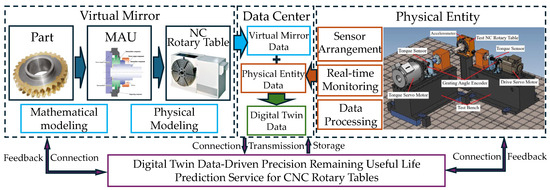
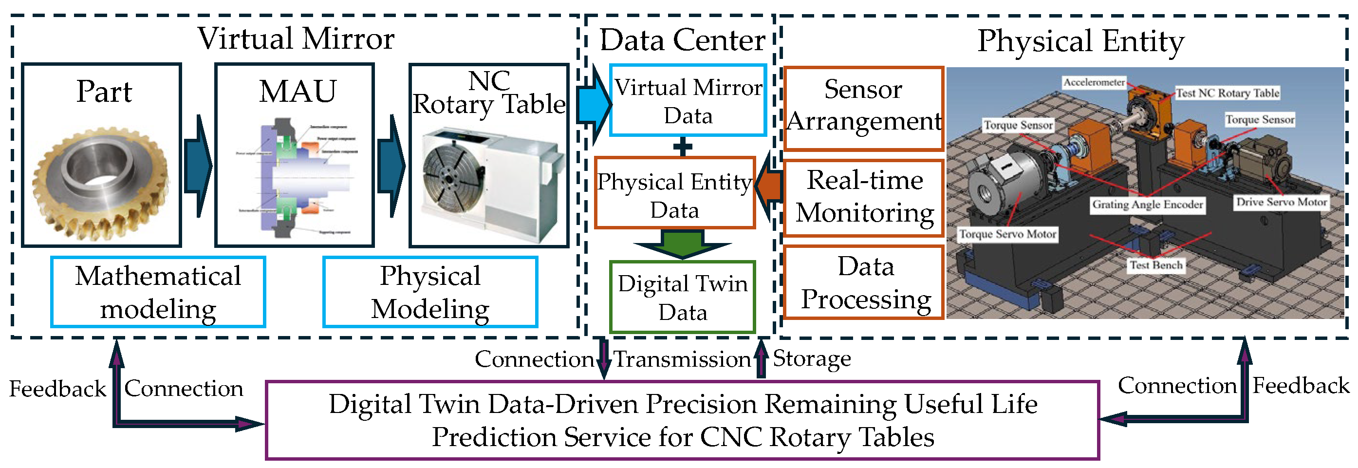
According to the five-dimensional digital twin model theory [25], the digital twin framework for precision remaining useful life (PRUL) prediction of CNC rotary tables mainly consists of five components—the virtual mirror, the physical entity, the data center, the connection system, and the service system—as illustrated in Figure 1. Among them, the physical entity refers to the actual CNC rotary table in operation along with its sensing and monitoring system, which is primarily responsible for real-time data acquisition of the rotary table’s precision indicators. To this end, a sensing scheme needs to be formulated to determine the sensor placement locations, signal acquisition system, and data processing methods. The virtual mirror, on the other hand, is a virtual model generated through physical modeling and mathematical modeling of the CNC rotary table. The data generated by the virtual mirror and the data acquired by the physical entity are both stored in the data center, where they are fused using appropriate methods to generate twin data, thereby providing support for subsequent services. The service system is responsible for outputting the prediction results of the digital twin framework, providing a basis for subsequent decision-making. The service executed in this paper is to utilize the twin data to achieve real-time and accurate prediction of the PRUL of the CNC rotary table. The connection system, using information transmission methods and interface protocols, enables data communication among the virtual mirror, physical entity, data center, and service system.
Figure 1.
Structure diagram of the digital twin framework for predicting precision remaining useful life of CNC rotary tables.
It should be particularly noted that the virtual mirror characterizes the theoretical precision degradation law of the CNC rotary table by means of numerical simulation techniques and physical mechanism models. A high-fidelity virtual mirror requires that the established model cover the main influencing factors and better reflect actual operating conditions. Therefore, when constructing the theoretical expression model for the PRUL of the CNC rotary table, the functional and kinematic essence of the rotary table must be considered. The Meta-action-based analysis method accounts for both component-level initial errors and unit-level motion errors, which is beneficial for improving the accuracy of the theoretical model. Meanwhile, empirical knowledge derived from historical data is also commonly employed in virtual mirror modeling [15].
3. Virtual Mirror Driven by Physical Models
In the virtual mirror, a theoretical expression model for the precision remaining useful life (PRUL) of the CNC rotary table needs to be established. According to the precision evolution mechanism of the CNC rotary table, the degradation of precision comprises two types of errors: first, the initial error resulting from the accumulation of manufacturing deviations in components; second, the time-varying error generated during the motion process.
3.1. Initial Precision Model Based on Error Propagation
During the manufacturing process of a CNC rotary table, machining errors of components arise due to factors such as the machining accuracy of machine tools, the skill level of operators, and uncertainties in the working environment. These errors gradually accumulate throughout the assembly process, forming the initial precision of the CNC rotary table. Therefore, it is necessary to formulate an error representation model and an error accumulation model. Prior to modeling, the following assumptions are made: all components involved in precision accumulation are considered rigid bodies; the contact surfaces during assembly are assumed to be rigid mating surfaces; and all errors are regarded as infinitesimal quantities relative to the geometric dimensions of the components. Accordingly, the specific modeling steps are as follows:
Step 1: Determination of error types. According to screw theory [22,26], the spatial pose of a component can be represented by coordinates along six degrees of freedom in a spatial coordinate system. Machining errors can be viewed as tiny offsets of the actual pose relative to the ideal pose. The mathematical expression is:
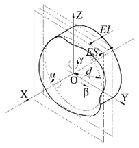
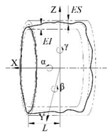
where υ = (Δx, Δy, Δz)T represents the infinitesimal translational displacements along the x, y and z directions, respectively, and θ = (Δα, Δβ, Δγ)T represents the infinitesimal rotational displacements about the α, β, and γ axes, respectively. According to the different degrees of freedom constrained by various errors of the CNC rotary table components, these errors can be classified into planar-type errors, cylindrical-type errors, and gear-type errors. The coordinate system construction and corresponding illustrations for different error types are given in Appendix B Table A3.
Planar-type errors result from the assembly of two planar surfaces, which constrains the degrees of freedom in the x, β, and γ directions. Consequently, the planar-type error can be expressed as TP:
Cylindrical-type errors result from the shaft–hole fit, which constrains the degrees of freedom in the y, z, β, and γ directions. Consequently, the cylindrical-type error can be expressed as TC:
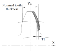
For CNC rotary tables, the gear-type errors that affect the output precision mainly include tooth thickness error and eccentricity error. Considering that both the tooth profile error and the tooth thickness error influence the tooth backlash, these two types of errors are collectively categorized as the tooth thickness error TT for computational convenience. It can be expressed as:
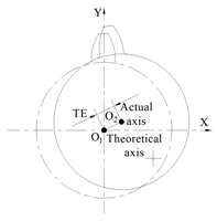
The eccentricity error TE of the gear typically constrains the translational degrees of freedom in the x and y directions. Therefore, it can be expressed as:
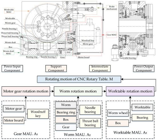
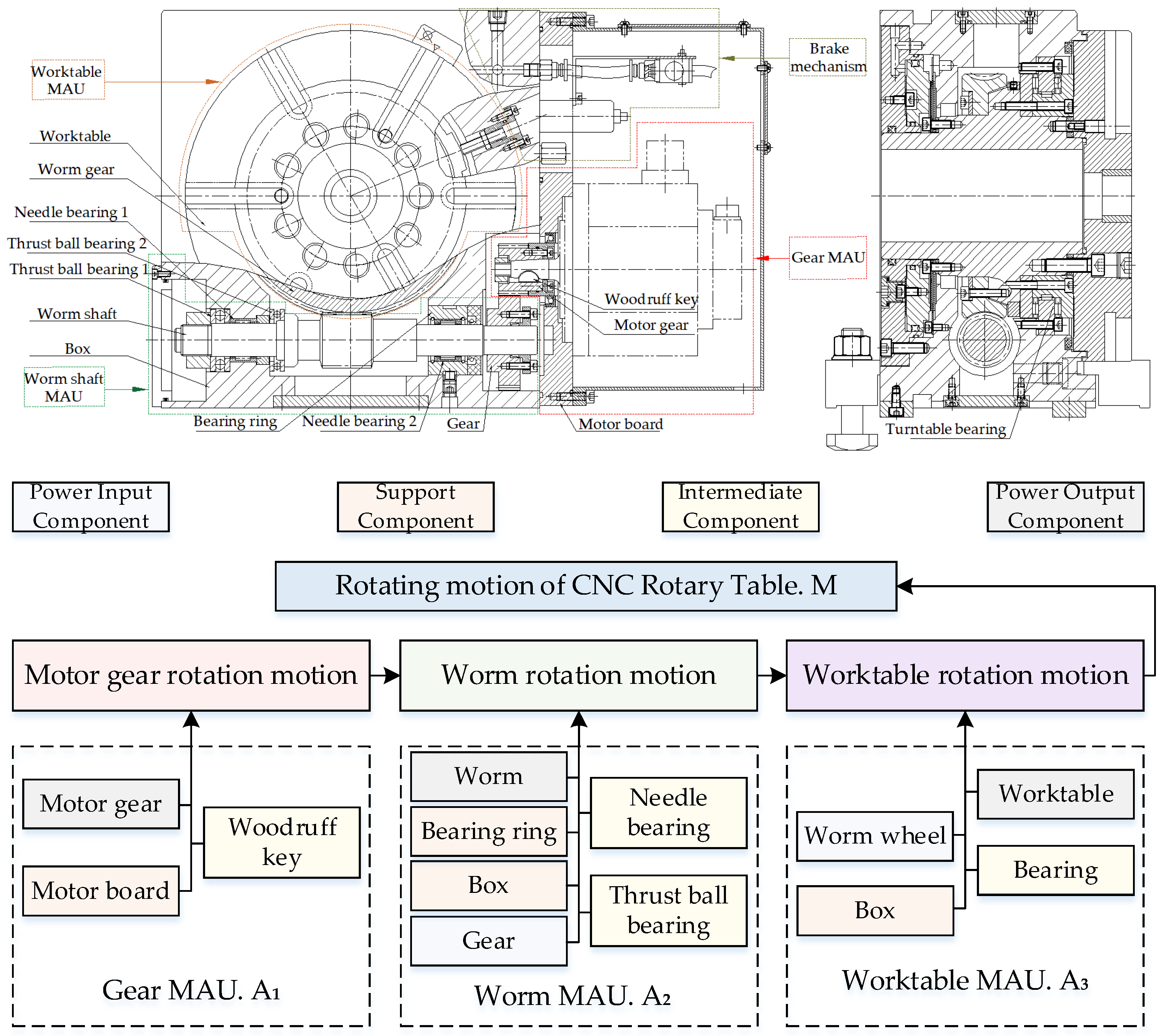
Step 2: Determine the error propagation path. The various geometric errors of components gradually accumulate along the assembly sequence, ultimately forming the output precision of the CNC rotary table. However, simply accumulating errors according to the assembly sequence alone would neglect the relative motion relationships of kinematic pairs. The Meta-action theory sorts the moving components in a mechanical system according to the motion transmission path, grouping other components rigidly connected to the moving component into one Meta-action unit, thereby achieving the separation of static and dynamic components in the mechanical system [22]. The structure and its structural decomposition results of the CNC rotary table are shown in Figure 2. It should be particularly noted that Figure 2 uses different colors to distinguish the five constituent components of a Meta-action unit. Since fasteners (e.g., screws) are standard and readily identifiable structures, they are not annotated in the figure to reduce the complexity of the structural decomposition diagram. In addition, the influence of the braking mechanism of the CNC rotary table on the output accuracy is negligible; therefore, it is also excluded from the structural decomposition. Within a Meta-action unit, attention is paid to the accumulation of geometric errors of each part according to the assembly sequence; between Meta-action units, attention is paid to the accumulation of errors according to the motion transmission sequence. This modeling approach better reflects the kinematic essence of mechanical systems [27].
Figure 2.
Structured decomposition of the CNC rotary table based on Meta-action theory.
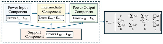
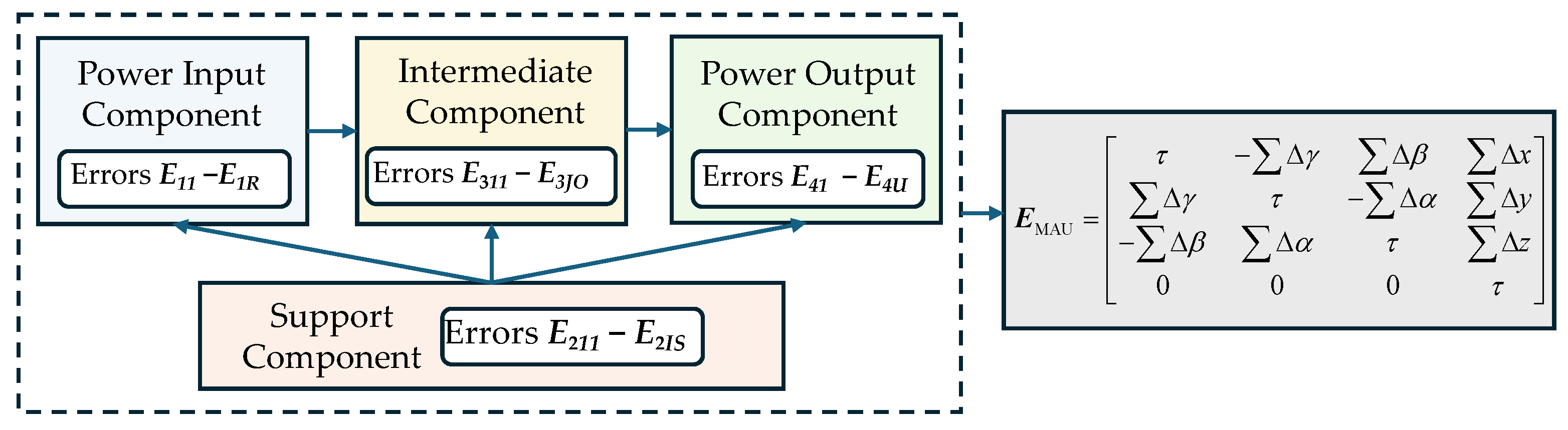
Step 3: Establishment of the initial precision model of the CNC rotary table. For precision modeling within a Meta-action unit, based on the characteristic that the Meta-action focuses on the moving component, the spatial pose state of the power output component is taken as the output precision of the Meta-action unit. Let the rth type of geometric error of the power input component within the Meta-action unit be denoted as E1r (r = 1, 2, …, R), the sth type of geometric errors of ith supporting components be denoted as E2is (i = 1, 2, …, I; s = 1, 2, …, S), the oth type of geometric errors of jth intermediate components be denoted as E3jo (j = 1, 2, …, J; o = 1, 2, …, O), and the uth type of geometric error of the power output component be denoted as E4u (u = 1, 2, …, U). Then, according to the error accumulation path within the Meta-action unit, as shown in Figure 3, the output precision EMAU of the Meta-action unit can be calculated as:
Figure 3.
Error accumulation path within the Meta-action unit.
For the specific CNC rotary table investigated in this paper, the tolerance ranges and distribution parameters of the errors considered in this study for each part are listed in Appendix C Table A4. Corresponding to Appendix C Table A4, the values of the error subscripts in each Meta-action unit are shown as Table 1. For rotary tables with different structures or when different types of errors are considered, the specific values of these subscripts should be determined on a case-by-case basis.
Table 1.
Values of error subscripts in each Meta-action unit.
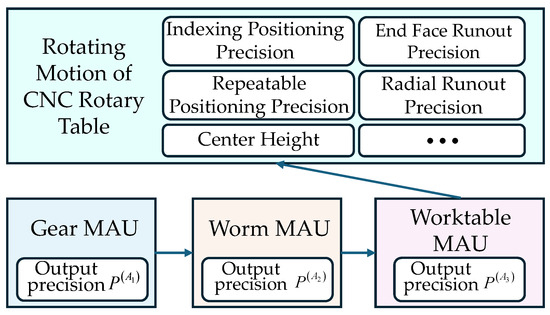
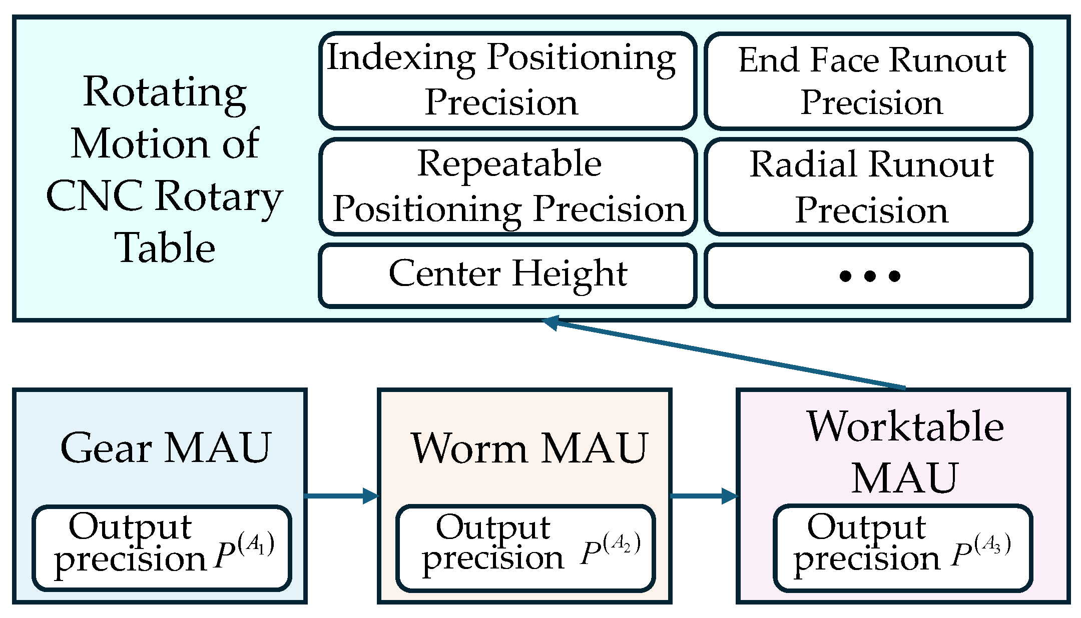
For precision modeling between Meta-action units, since the output precision of a CNC rotary table involves multiple indicators—such as indexing positioning accuracy, repeat positioning accuracy, and face runout—different precision indicators represent errors in different directions within the spatial coordinate system. As the smallest motion unit in a CNC rotary table, when analyzing a specific precision indicator of the rotary table, the error component of the Meta-action unit in the corresponding direction should be taken as the output precision of that Meta-action unit. The error accumulation process between Meta-action units is illustrated in Figure 4.
Figure 4.
Error accumulation process of the inter-Mate-Action Units.
The accuracy considered in this paper for the CNC rotary table is primarily the indexing positioning accuracy, and its main influencing factor is the backlash between the gear pair and the worm gear pair. As shown by the gear-type errors in Appendix B Table A3, the output errors of the Gear MAU and the Worm MAU are both their components along the x-direction. Since the worktable of the CNC rotary table is rigidly connected to the worm wheel, the indexing positioning error of the worktable mainly depends on the motion error of the worm wheel. Considering the coordinate system arrangements for both gear-type errors (worm wheel) and cylindrical-type errors (worktable), the y-axis of the worktable part coordinate system aligns with the x-axis of the worm wheel part coordinate system. Consequently, the output error of the Worktable MAU is its component along the y-direction. Accordingly, let the output precision of the Gear MAU in the x-direction be denoted as , the output precision of the Worm MAU in the x-direction be denoted as , and the output precision of the Worktable MAU in the y-direction be denoted as . Then, the initial assembly precision PR of the CNC rotary table can be expressed as:
The output error of a Meta-action unit is the error accumulation of its constituent parts along the output direction. According to Appendix B Table A3, the planar-type error has three components (Δβ, Δγ and Δx), the cylindrical-type error has four components (Δβ, Δγ, Δy and Δz), the tooth thickness error has one component (Δx) and the eccentricity error has two components (Δx and Δy). Since the contribution distributions of different error components to different error types are difficult to obtain, this paper assumes that the contribution degree of each error component is equal across all error types. Therefore, after taking the arithmetic mean of each type of error, the value of each error component can be obtained, and these values are identical. Based on this, according to the error types and component numbers for each part in each Meta-action unit listed in Appendix C Table A4, the distribution data of , , and can be calculated as follows:
where n is the component number for the corresponding error type, which can be found in Appendix C Table A4.
Therefore, the distribution of the initial assembly accuracy PR of the CNC rotary table can be calculated as follows:
3.2. Mathematical Expression Model for Time-Varying Errors
Due to the characteristics of substantial heat generation and susceptibility to wear inherent in worm gear drives, thermal error and wear error constitute the primary error sources affecting the precision life of CNC rotary tables. Therefore, it is necessary to perform theoretical modeling of these two types of errors from the perspective of numerical analysis.
3.2.1. Thermal Error Simulation
Thermal error generally requires solving via the finite element method to obtain the thermal deformation of components within a steady-state temperature field. Considering that frictional heat is typically concentrated on the contacting tooth surfaces where relative motion occurs, and has a relatively minor effect on other fixedly connected components within the Meta-action unit, for ease of solution, the thermal error primarily considers the thermal deformation of the worm wheel and the worm.
It should be noted that the thermal error simulation is subject to three assumptions: (1) the mechanical structure is treated as a continuous, isotropic medium; (2) upon reaching thermal equilibrium, the temperature field is steady and uniformly distributed; and (3) the thermal conductivity, specific heat capacity, linear expansion coefficient, and elastic modulus are all taken as constant values throughout the simulation.
The specific simulation steps are as follows:
Step 1: Denote the temperature field of the worm gear pair in the Cartesian coordinate system as T = T(x,y,z,t). Under steady-state conditions, after a period of heat exchange, the heat Q inside the worm gear pair and on its boundaries results in a stable temperature at each point of the components, i.e.,
Therefore, given the temperature field T = T(x,y,z,t), the three-dimensional steady-state heat conduction model can be expressed as:
where λx, λy, λz is the thermal conductivity coefficient of the material in each direction; ϕ is the internal heat source; ρ is the density of the material; c is the specific heat capacity.
Step 2: The internal heat source of the worm gear pair is primarily the heat generated by friction. Therefore, the formula for the instantaneous frictional heat flux per unit area on the contact surface of the worm gear pair, denoted as qm, is:
where f is the friction coefficient of the worm gear pair; p is the contact stress; vs is the relative sliding velocity.
qm = fpvs
Step 3: Determine the boundary conditions on each surface of the worm gear pair. The tooth meshing zone is subjected to both frictional heat flux and convective thermal boundary conditions, simultaneously satisfying the Neumann boundary condition and the third kind of boundary condition. The boundary conditions can be expressed as:
where is the temperature gradient; hm is the convective heat transfer coefficient of the tooth meshing zone; Tm is the medium temperature for convective heat transfer in the tooth meshing zone.
The tooth tip surface, tooth root surface, non-working areas of the meshing surface, and the end faces of the worm wheel are all subject solely to convective heat transfer boundary conditions, which satisfy the third kind of boundary condition. The boundary conditions can be expressed as:
where hs is the convective heat transfer coefficient of the non-working area; Ts is the medium temperature for convective heat transfer in the non-working area.
The bottom surface of the worm wheel is located far from the meshing zone and can therefore be assumed to be an adiabatic surface. The boundary condition is:
Step 4: According to the empirical formula, the heat partition coefficient β between the worm and the worm wheel is given by:
where λ1 and λ2 are the thermal conductivities of the worm wheel and worm materials, respectively; ρ1 and ρ2 are the densities of the worm wheel and worm materials, respectively; c1 and c2 are the specific heat capacities of the worm wheel and worm materials, respectively; υ1t and υ2t are the relative tangential velocities of the worm wheel and worm at the meshing point, respectively.
Step 5: Establish a finite element model of the worm gear pair, assign the material properties of the components, perform mesh generation, apply boundary conditions such as heat flux and convective heat transfer coefficients, and solve for the thermal strain results ehw and ehg of the worm wheel and the worm under the steady-state temperature field.
3.2.2. Wear Error Modeling
The wear errors in CNC rotary tables primarily stem from the wear of the worm wheel and the wear of the rotary table bearing. Since the worm wheel is typically made of copper alloy while the worm is usually made of alloy steel, this material combination leads to a significantly higher wear rate of the worm wheel, which is generally much greater than that of the worm and gears. The rotary table bearing, due to its substantial load-bearing requirements, exhibits a wear rate far exceeding that of other bearings. Therefore, this paper employs the Archard wear model to calculate the wear errors of the worm wheel and the bearing. By discretizing the wear process, the wear amount at each infinitesimal time step is obtained as:
where k is the wear coefficient of the material; p is the contact stress in the contact zone; vs is the relative motion velocity of the contact surface.
The infinitesimal time interval Δt for each contact can be calculated as:
where q is the half-width of the Hertz contact zone, which can be calculated according to the Hertz contact equations.
For the worm wheel, the relative motion velocity vws can be calculated as:
where d1 is the pitch diameter of the worm; n1 is the rotational speed of the worm; γ is the lead angle.
The contact stress between the worm and the worm wheel can be calculated as:
where, since the worm wheel rotary table typically operates under a stable load, the load factor K = 1; T2 is the torque of the worm wheel; m is the module of the worm; Z2 is the number of teeth of the worm wheel.
Let the rotational speed of the CNC rotary table be , the operating time be t, and the wear amount at each contact instant be Δhw. Then the total wear amount on the tooth surface of the worm wheel can be calculated as:
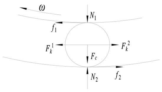
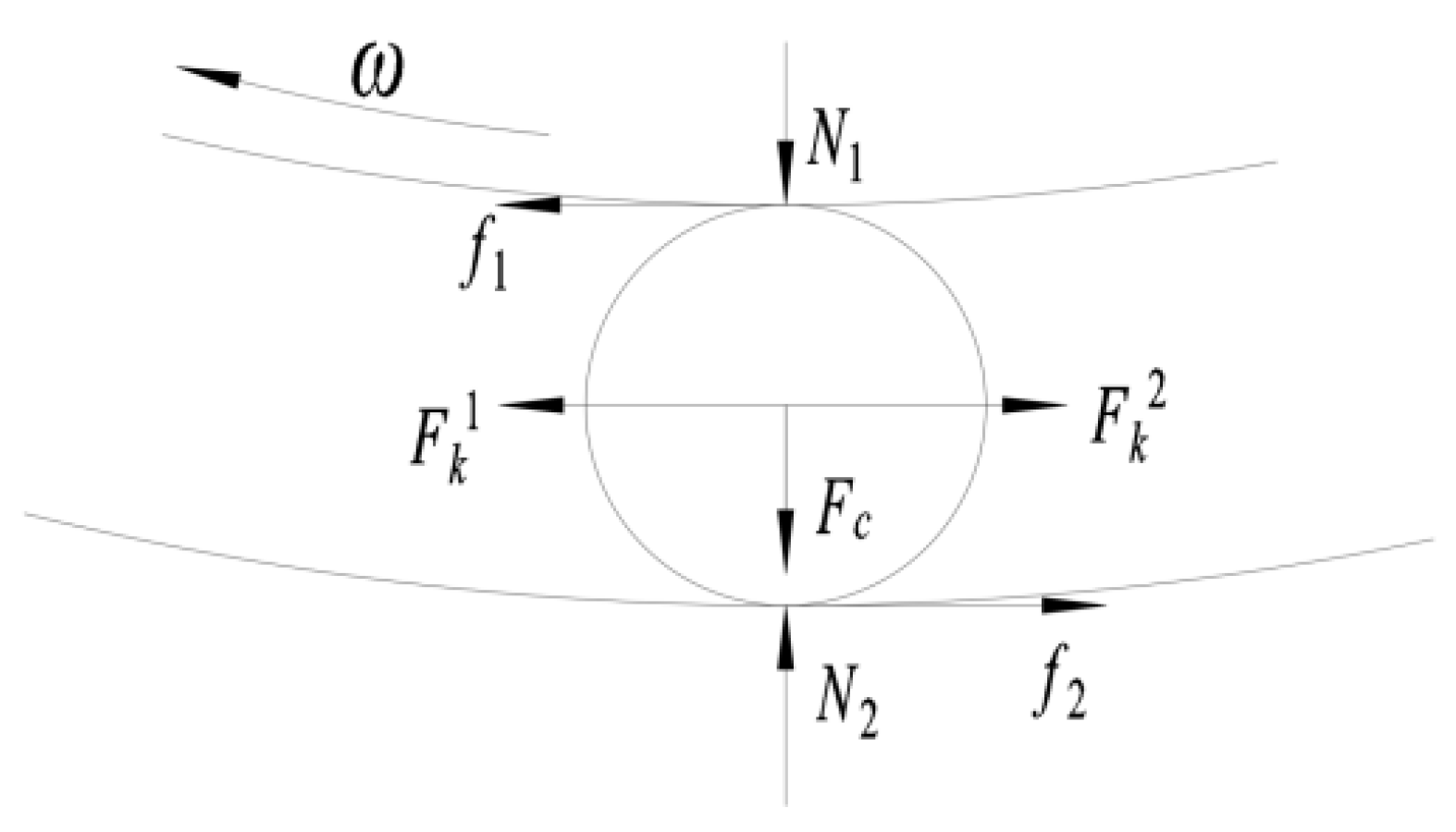
For the rotary table bearing, the main wear locations are the outer raceway, the inner raceway, and the rollers. The forces acting on the rollers are shown in Figure 5. Considering that the output rotational speed of the rotary table is relatively low, the centrifugal force FC can be neglected. The pressure N1 on the inner raceway and the supporting force N2 on the outer raceway are determined by the weight of the worktable and the load. f1 and f2 are the frictional forces, while and are the forces exerted by the cage on the rollers. Accordingly, the contact stress between the rollers and the raceways can be calculated as:
where qg is the half-width of the Hertz contact zone.
Figure 5.
Force Analysis of the Roller.
The rotational speed of the inner ring of the rotary table bearing is equal to the rotational speed of the rotary table. Let the contact circle diameter of the inner raceway be R1. Then the relative motion velocity vgs between the roller and the raceway can be calculated as:
The wear amount egw(t) of the rotary table bearing can be calculated as:
where R0 is the diameter of the roller, z is the number of rollers, and Δh1, Δh2 and Δh3 are the wear amounts per contact of the inner raceway, the roller, and the outer raceway, respectively, calculated by Equation (17).
3.3. Theoretical Model of Precision Remaining Useful Life
The accumulation of errors during the manufacturing process of a CNC rotary table forms its initial output precision, while time-varying errors such as component wear and aging during operation cause the degradation of the output precision. In addition, the CNC rotary table is also subject to various environmental factors under actual working conditions, leading to uncertainty in the output precision. This results in a phenomenon of fluctuated degradation in the actual output precision of the CNC rotary table. The Wiener process model is well suited for the quantitative characterization of such stochastic degradation processes [28]. Let X(t);t ≥ 0 denote the output precision. Then the Wiener process model can be expressed as:
where x0 is the initial output precision of the CNC rotary table, which can be solved using the models in Section 3.1 and Section 3.2; μ is the drift coefficient related to the degradation rate, which can be obtained from the wear amount calculation model in Section 3.2; σB is the diffusion coefficient associated with the degree of uncertainty; B(t) is the standard Brownian motion. Since the uncertainty of the operating process is difficult to quantify theoretically using a physical model, it can be fitted using historical data from similar products.
X(t) = x0 + μt + σBB(t)
Let the precision threshold of the CNC rotary table be denoted as ξ. Then the precision life of the CNC rotary table can be defined as the time when the output precision first reaches the precision threshold, expressed as:
T = inf{t:X(t) ≥ ξ|X(0) < ξ)}
And the time duration from any given time ti until the output precision first reaches the precision threshold is the precision remaining useful life of the CNC rotary table at time ti, denoted as:
TRUL = inf{t : X(t + ti) ≥ ξ|X(ti) < ξ)}
According to the properties of the Wiener process model, the precision remaining useful life TRUL follows an inverse Gaussian distribution. Let the output precision of the rotary table at any arbitrary time ti be . Therefore, the distribution function of the precision remaining useful life of the CNC rotary table at time ti can be expressed as:
The probability density function of the precision remaining useful life of the CNC rotary table at time ti can be expressed as:
4. Monitoring Data-Driven Physical Entity
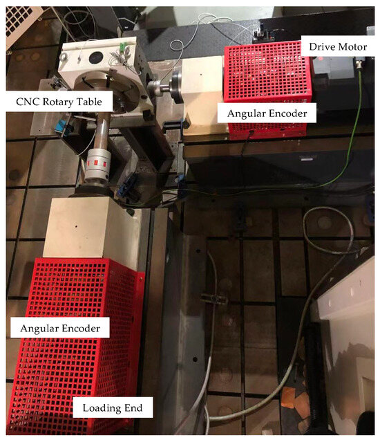
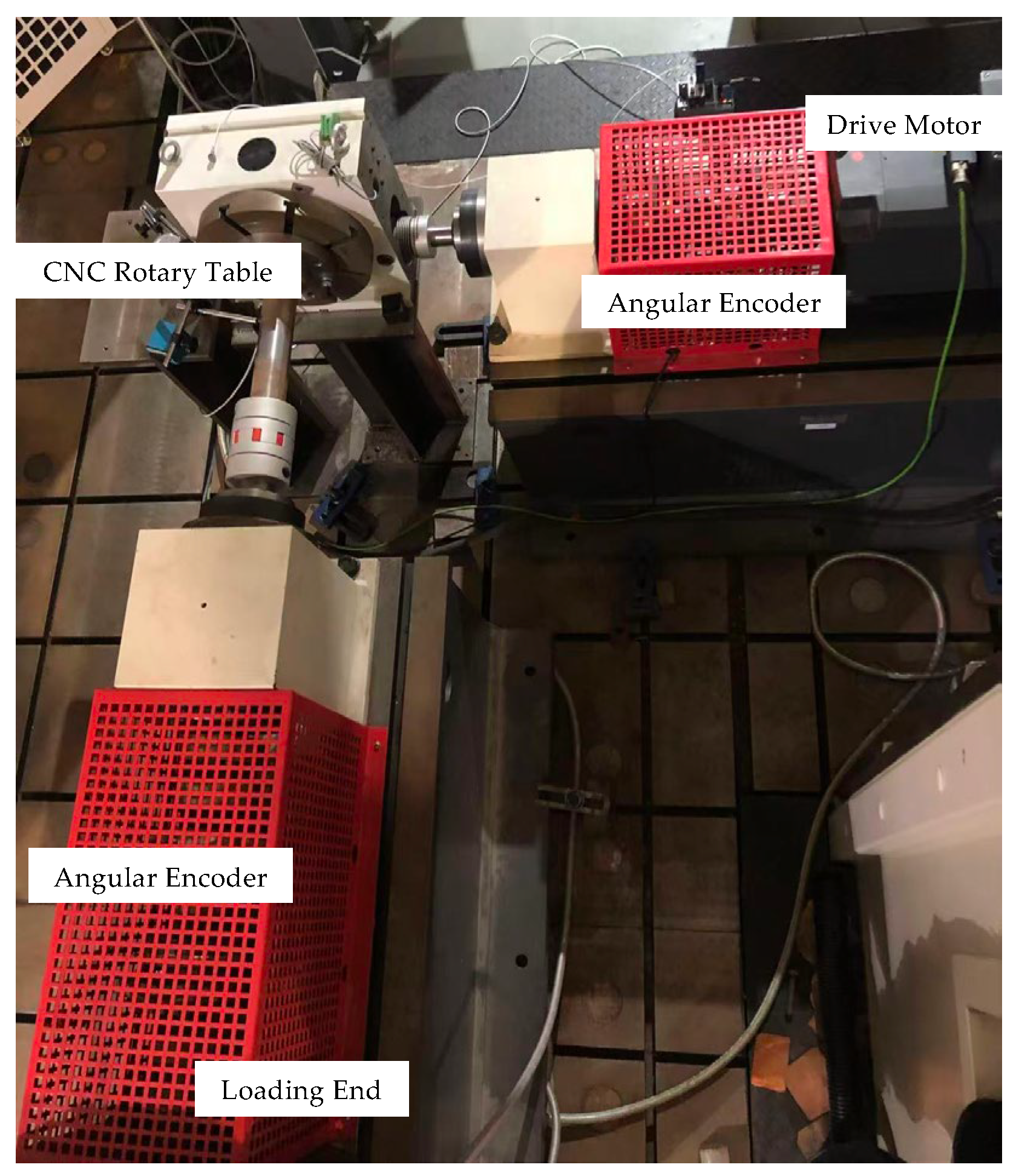
Real-time monitoring data are characteristic quantities that reflect the actual operating state of a CNC rotary table, acquired through sensor technology and signal acquisition techniques. They can truthfully represent the precision life status of the CNC rotary table. However, the accuracy of these data depends on the precision of the sensors and the interference from environmental noise. Therefore, when designing the monitoring scheme, several factors need to be considered: the sensor arrangement should not interfere with the normal operation of the rotary table; the number of interference points in the acquisition process should be minimized; the acquired precision indicators should directly or indirectly reflect the precision status of the CNC rotary table; and the sampling interval should not be excessively large so as to capture the fluctuations of the precision indicators. In this study, a precision life test bench for CNC rotary tables was employed to simulate the working state under actual load conditions and to acquire real-time precision monitoring data. As shown in Figure 6, the test bench consists of five components: the CNC rotary table body, the drive motor, the load motor, the sensing system, and the supporting base. The sensors used are two angular encoders installed at the driving end and the loading end, whose performance specifications are listed in Table 2. The difference between the readings of the two encoders constitutes the indexing positioning accuracy of the CNC rotary table. Test conditions were set according to typical working loads, output rotational speeds, and output torques, and the real-time monitoring data were recorded and stored.
Figure 6.
Precision life test bench of CNC rotary table.
Table 2.
Main performance index of grating angle encoder.
5. Digital Twin Data-Driven PRUL Prediction Service for CNC Rotary Tables
The theoretical simulation data obtained from the virtual mirror reflect the general pattern of precision life variation common to a class of CNC rotary tables, but they are unable to quantitatively express the random disturbances occurring during the operation of an individual rotary table. On the other hand, the quality of monitoring data acquired from the physical entity depends on the accuracy of the sensors and the duration of data acquisition, which may reduce the credibility of the prediction results. Therefore, the twin data generated by combining theoretical data with real-time data can integrate general laws with real-time characteristics, thereby not only reflecting the real-time stochastic state of the CNC rotary table but also enhancing the interpretability of the prediction results. According to the Wiener process model, three parameters need to be determined: the initial value, the drift coefficient, and the diffusion coefficient. Accordingly, the digital twin data-driven service for predicting the precision remaining useful life of CNC rotary tables primarily focuses on correcting these three parameters, thereby achieving both accuracy and real-time capability in the prediction results.
First, the initial precision value of the CNC rotary table calculated in the virtual mirror is taken as the sum of the mean value of the normal distribution and the steady-state thermal error. However, the initial precision varies from one rotary table to another. Moreover, considering that a certain period of time is required for the CNC rotary table to reach thermal equilibrium from startup, the precision data during this period primarily exhibit random fluctuations, and such random factors only appear in the early stage of operation. Therefore, to mitigate the influence of random factors in the initial stage, the minimum value of the output error after a period of operation in the real-time data is taken as the initial precision value x0d of the CNC rotary table, and the data prior to this minimum value are discarded when calculating the drift coefficient and the diffusion coefficient.
Second, let the real-time monitoring data acquired from the physical entity be denoted as (xi,ti), i = 1, 2, …n. The drift coefficient μp is then fitted using linear regression as:
where is the mean value of the precision data and is the mean value of the time data.
Let the drift coefficient calculated from the virtual simulation be denoted as μv. Then the corrected drift coefficient μd can be calculated as:
Thirdly, let the diffusion coefficient obtained by substituting the real-time monitoring data into the Wiener process model be denoted as σBp, and the diffusion coefficient obtained by substituting historical data from similar products into the model be denoted as σBv. Then the corrected diffusion coefficient σBd can be calculated as:
Finally, by substituting the three corrected parameters into Equation (29), the predicted values of the precision remaining useful life of the CNC rotary table at different time instants under the digital twin data-driven framework are obtained, thereby providing a basis for subsequent operation and maintenance decision-making.
6. Case Study
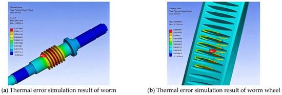
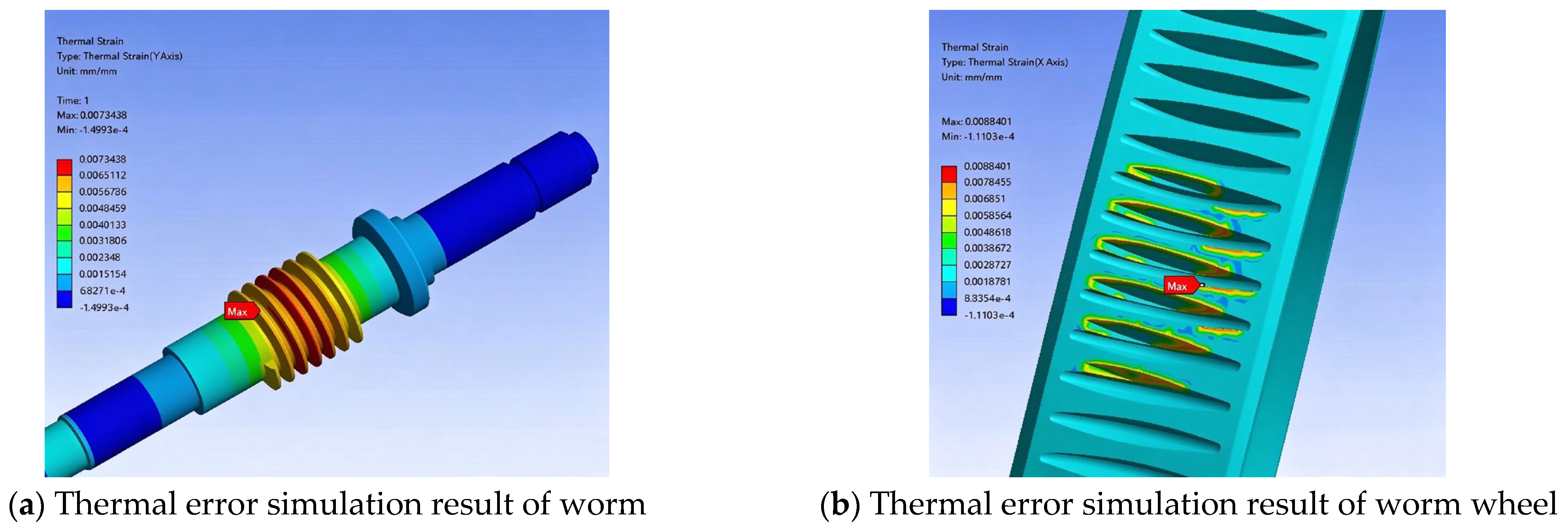
This paper presents a case study on the TK13 series CNC rotary table manufactured by a domestic machine tool accessory enterprise. The output precision indicator is the indexing positioning accuracy, and the precision threshold is set to ξ = 40 μm. Based on the error types and distributions in Appendix C Table A4 combined with Equations (1)–(9), the initial assembly precision of the CNC rotary table is calculated as PR∼N(4.5,32.01). Based on Section 3.2, the thermal error simulation is performed, and the results are shown in Figure 7.
Figure 7.
Thermal error simulation result of the worm gear pair.
The thermal deformation of the worm under the steady-state temperature field is 7.3438 μm, and that of the worm wheel is 8.8401 μm. Consequently, the theoretical initial precision value of the CNC rotary table obtained from the virtual mirror is:
x0v = 4.5 + 7.3438 + 8.8401 = 20.684 μm
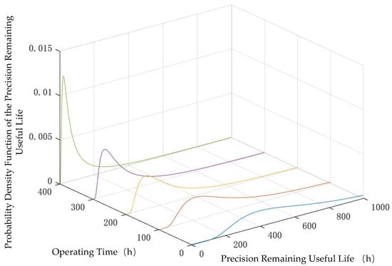
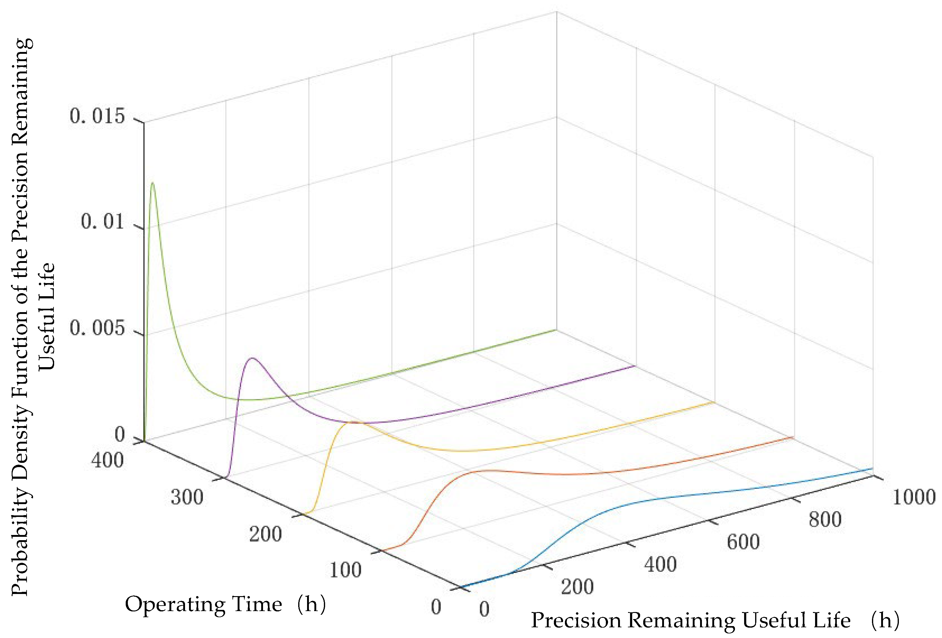
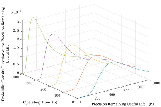
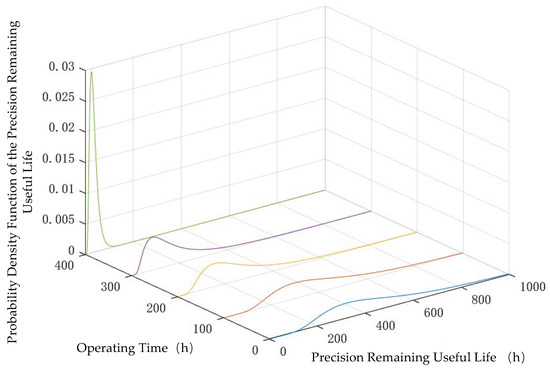
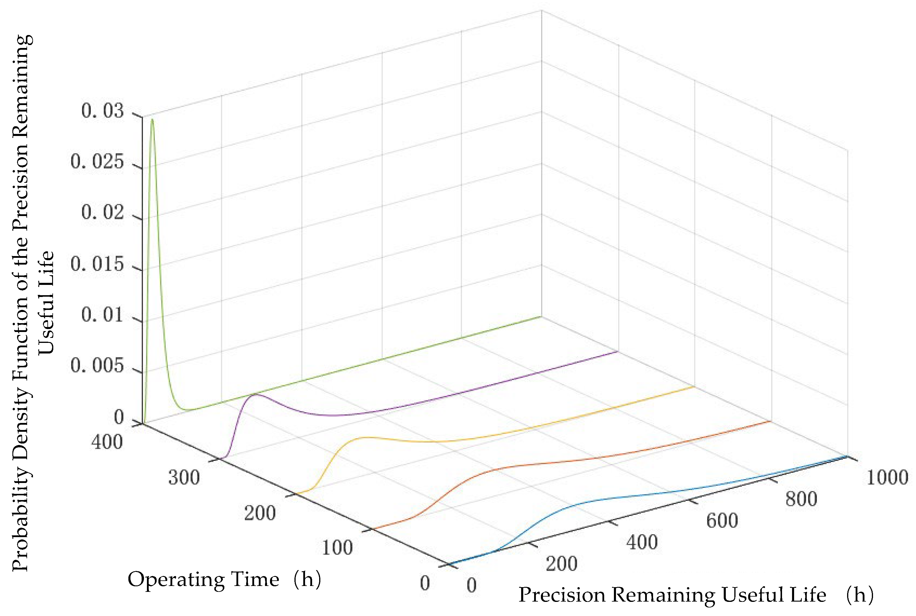
The worm gear pair uses extreme pressure gear oil for lubrication, with a lubricant pressure–viscosity coefficient of 1.6819 × 10⁻⁸ m2/N. The surface roughness of the worm is 1.6 μm, and that of the worm wheel is 0.4 μm. The friction coefficient of the worm gear pair is 0.145. Based on the Janakiraman regression formula from reference [29], the wear coefficient k is calculated to be 7.6939 × 10⁻⁶ μm2/N. By substituting the material parameters of the worm gear pair from Reference [30], the material parameters of the rotary table bearing from Reference [31], and the data from Appendix D Table A5, Table A6 and Table A7 into Equations (17)–(24), the theoretical drift coefficient μv = 0.033 μm/h derived from the virtual mirror can be calculated. The theoretical diffusion coefficient is obtained by substituting the historical data of similar products from Reference [32] into the Wiener process model. Subsequently, by substituting the three calculated parameters x0v, μv, and σBv into Equation (29), the probability density functions of the precision remaining useful life of the CNC rotary table at 0 h, 100 h, 200 h, 300 h, and 400 h under the virtual mirror data-driven framework are solved and obtained, as shown in Figure 8.
Figure 8.
Predicted results of precision remaining useful life of the CNC rotary table at different time instants under the virtual mirror data-driven framework.
Based on the CNC rotary table precision life test bench and the experimental scheme described in Section 4, experiments were carried out. Due to the slow precision degradation rate of the CNC rotary table, and considering the resolution of the angular encoders, the indexing positioning accuracy data were recorded at intervals of 15 h. Given that the output precision in the Wiener process model is a distance value, the angular data collected by the angular encoders were converted into arc length data. Thus, the monitoring data obtained over 450 h are listed in Table 3.
Table 3.
Real-time data from physical entity.
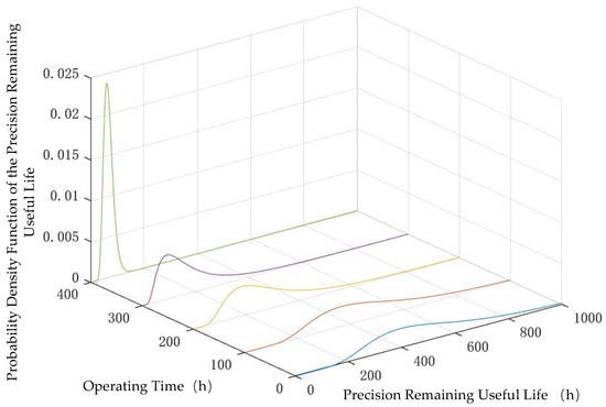
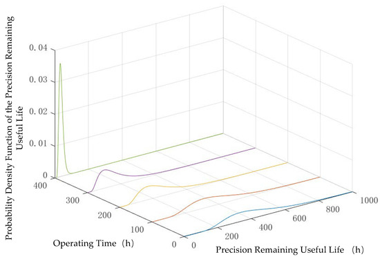
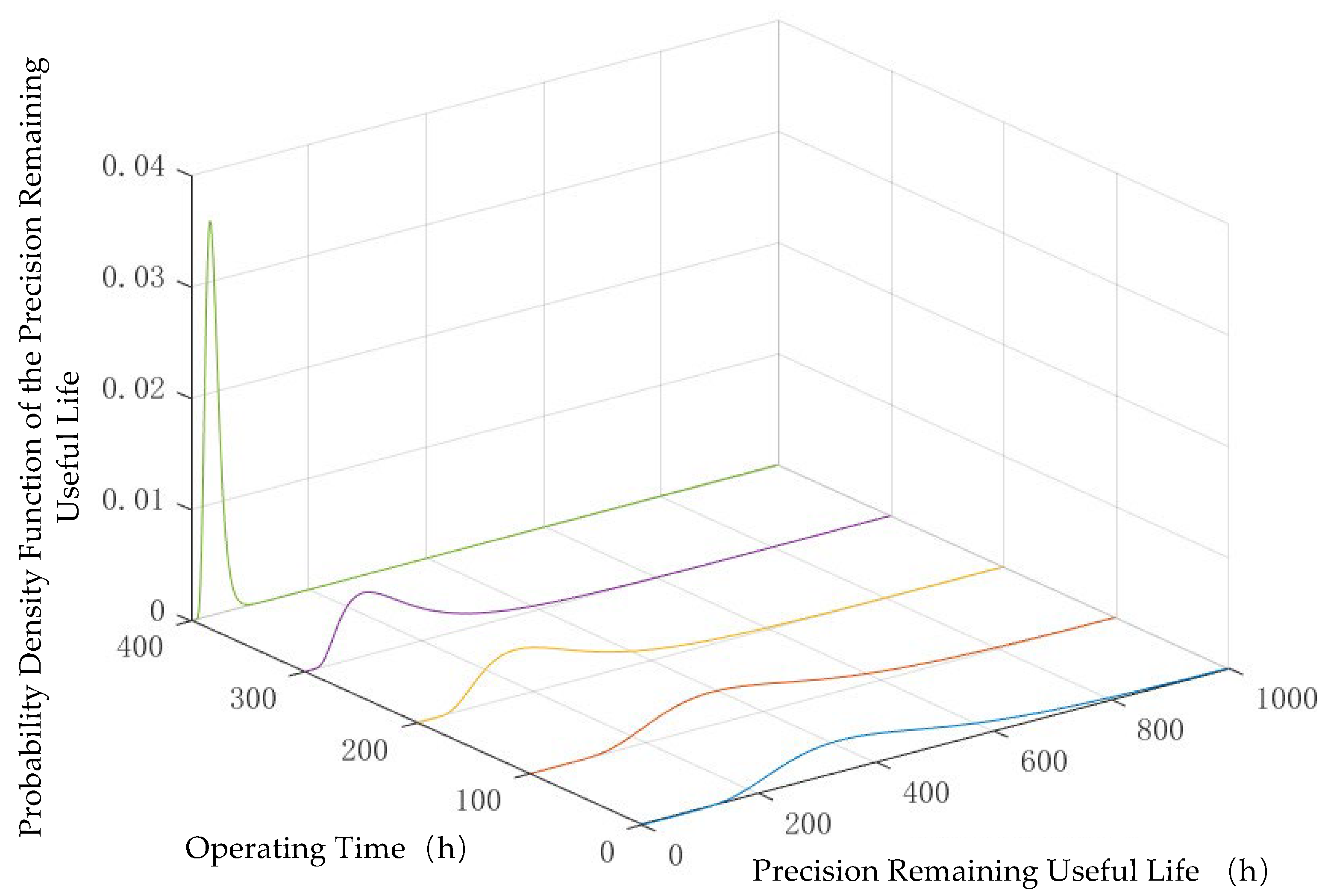
Monitoring data from 0 h to 180 h were selected for analysis. The actual initial precision value x0p = 26.703 μm of the CNC rotary table was determined. The real-time drift coefficient μp = 0.0198 μm/h was calculated according to Equation (30). By substituting the data into the Wiener process model, the real-time diffusion coefficient was obtained. Substituting these three parameters into Equation (29), the probability density functions of the precision remaining useful life of the CNC rotary table at 0 h, 100 h, 200 h, 300 h, and 400 h under the monitoring data-driven framework from 0 h to 180 h were solved and obtained, as shown in Figure 9.
Figure 9.
Predicted results of precision remaining useful life of the CNC rotary table at different time instants under the 0–180 h monitoring data-driven framework.
Subsequently, by combining the virtual simulation data with the monitoring data from 0 h to 180 h, the precision initial value x0d = 26.703 μm of the CNC rotary table under the twin data-driven framework is obtained. The corrected drift coefficient μd = 0.026391 μm/h is obtained according to Equation (31), and the corrected diffusion coefficient is obtained according to Equation (32). Substituting these three parameters into Equation (29), the probability density functions of the precision remaining useful life of the CNC rotary table at 0 h, 100 h, 200 h, 300 h, and 400 h under the twin data-driven framework from 0 h to 180 h are solved and obtained, as shown in Figure 10.
Figure 10.
Predicted results of precision remaining useful life of the CNC rotary table at different time instants under the 0–180 h twin data-driven framework.
The comparison of predicted precision remaining useful life of the CNC rotary table at 0 h, 100 h, 200 h, 300 h, and 400 h under different data-driven frameworks from 0 h to 180 h, obtained from Figure 8, Figure 9 and Figure 10, is summarized in Table 4. The comparison results indicate that, due to the small volume of monitoring data from 0 h to 180 h, the prediction based solely on monitoring data exhibits a relatively large deviation. For example, the monitoring data-driven prediction yields a precision remaining useful life of 302 h when the rotary table has operated for 200 h, which is far greater than the actual value of 235 h, and a precision remaining useful life of 152 h when the rotary table has operated for 400 h, which differs significantly from the actual value of 35 h. In contrast, the twin data can improve prediction accuracy to a certain extent. Moreover, compared with the prediction driven solely by virtual mirror data, the integration of real-time data enables the predicted results at most time points—such as 200 h and 300 h—to be closer to the true values.
Table 4.
Comparison of predicted PRUL values of the CNC rotary table at different time instants under various data-driven frameworks from 0 to 180 h.
Furthermore, monitoring data from 0 h to 360 h were selected for analysis. The actual initial precision value x0p = 26.703 μm of the CNC rotary table was determined. The real-time drift coefficient μp = 0.0300 μm/h was calculated according to Equation (30). By substituting the data into the Wiener process model, the real-time diffusion coefficient was obtained. Substituting these three parameters into Equation (29), the probability density functions of the precision remaining useful life of the CNC rotary table at 0 h, 100 h, 200 h, 300 h, and 400 h under the 0 h to 360 h monitoring data-driven framework were solved and obtained, as shown in Figure 11.
Figure 11.
Predicted results of precision remaining useful life of the CNC rotary table at different time instants under the 0–360 h monitoring data-driven framework.
Subsequently, by combining the virtual simulation data with the monitoring data from 0 h to 360 h, the initial precision value x0d = 26.703 μm of the CNC rotary table under the digital twin data-driven framework is obtained. The corrected drift coefficient μd = 0.031491 μm/h is obtained according to Equation (31), and the corrected diffusion coefficient is obtained according to Equation (32). Substituting these three parameters into Equation (29), the probability density functions of the precision remaining useful life of the CNC rotary table at 0 h, 100 h, 200 h, 300 h, and 400 h under the 0 h to 360 h digital twin data-driven framework are solved and obtained, as shown in Figure 12.
Figure 12.
Predicted results of precision remaining useful life of the CNC rotary table at different time instants under the 0–360 h twin data-driven framework.
The comparison of predicted precision remaining useful life values of the CNC rotary table at 0 h, 100 h, 200 h, 300 h, and 400 h under different data-driven frameworks from 0 h to 360 h, obtained from Figure 10 and Figure 11, is summarized in Table 5. According to the twin data-driven prediction, the precision remaining useful life is 32 h when the rotary table has operated for 400 h. Compared with the predicted value of 22 h from the virtual mirror data and the predicted value of 26 h from the monitoring data, the twin data-driven result is closer to the actual value of 35 h. This demonstrates that the precision remaining useful life prediction results driven by digital twin data are significantly superior to those driven solely by virtual mirror data or solely by monitoring data, thereby validating the effectiveness of the proposed method.
Table 5.
Comparison of predicted PRUL values of the CNC rotary table at different time instants under various data-driven frameworks from 0 to 360 h.
In summary, combining the prediction results shown in Table 4 and Table 5, the Mean Absolute Error (MAE) and Root Mean Square Error (RMSE) of the three prediction methods are calculated, as shown in Table 6.
Table 6.
Comparison of prediction errors across different methods.
Taking the prediction errors based on twin data as the benchmark, a comparison is made with the prediction errors based on virtual mirror and monitoring data, and the comparison results are shown in Table 7.
Table 7.
Error reduction ratios of the digital twin-driven method relative to other methods.
As shown in Table 7, the digital twin-driven prediction method exhibits lower MAE and RMSE values. In the 0–180 h stage, the MAE reductions relative to both virtual mirror and monitoring data exceed 47%, while the RMSE reductions surpass 53%. In the 0–360 h stage, both MAE and RMSE still achieve reductions of over 16%. These results demonstrate that the prediction accuracy and stability achieved by fusing twin data are significantly superior to those obtained using either virtual mirror data or monitoring data alone, effectively improving the remaining useful life prediction accuracy and validating the feasibility of the proposed method.
7. Conclusions
This paper addresses the problem of real-time precision remaining useful life (PRUL) prediction for CNC rotary tables. A five-dimensional digital twin framework was established. Based on the Meta-action unit theory, a theoretical PRUL prediction model incorporating both initial errors and time-varying errors was proposed. The data acquisition requirements for the physical entity were clarified, and correction rules for model parameters driven by digital twin data were formulated, thereby realizing a real-time PRUL prediction service for CNC rotary tables. Case study results demonstrate that the proposed method can provide an effective model foundation for predictive maintenance. The main conclusions are as follows:
(1) By modeling the initial precision and time-varying errors of the CNC rotary table, and solving the Wiener process model parameters using historical data from similar products, a theoretical PRUL prediction model for the CNC rotary table was obtained. This model is capable of predicting the PRUL in the absence of real-time monitoring data; however, the prediction results are insufficiently accurate.
(2) Under conditions where the amount of real-time monitoring data is limited, the prediction results driven solely by monitoring data exhibit considerable deviations. In contrast, the twin data generated by fusing theoretical model data with monitoring data can correct parameters within the model, thereby effectively improving prediction accuracy. As shown in Table 7, the prediction errors based on twin data are substantially lower than those of either virtual mirror data or monitoring data. Particularly in the 0–180 h stage, all error reduction rates approach or exceed 50%. In the 0–360 h stage, even as the amount of monitoring data increases, the twin data method still maintains error reductions of over 16%. These results indicate that twin data-driven prediction overcomes the limitations of relying on a single data source (either a physical model or monitoring data), while also enhancing the accuracy and stability of remaining useful life prediction, thereby validating the effectiveness of the proposed method.
(3) The digital twin-driven prediction method integrates real-time monitoring data, enabling accurate real-time predictions based on the output precision data of each individual CNC rotary table, thereby providing a basis for customized maintenance. In addition, considering that CNC rotary tables often involve multiple precision indicators, future research will analyze the coupling relationships among these indicators and establish a PRUL prediction model covering multiple indicators, so as to further enhance the applicability of the method.
(4) The effectiveness of this method has been validated on the CNC rotary table, and its core concept can be extended to other complex mechanical structures. By integrating simulation data with measured data and establishing a digital twin framework, it is expected to achieve accurate PRUL prediction for different mechanical structures, thereby enhancing the generality and engineering application value of the proposed method.
Furthermore, the present study has certain limitations. Due to the limited scale of currently available monitoring data for CNC rotary tables, a relatively conservative fusion strategy (e.g., arithmetic averaging) was adopted when integrating the physical model with real-time data, rather than employing more precise fusion approaches such as adaptive weighting. In future work, as monitoring data continue to accumulate, adaptive weighting-based fusion methods will be explored to further improve prediction accuracy. On the other hand, accurate thermal deformation analysis of gear meshing and worm gear pairs remains challenging. Constrained by computational complexity, the present study did not adopt a high-precision thermal deformation analysis method, which may affect the prediction accuracy of the PRUL of CNC rotary tables to some extent. Future research will explore PRUL prediction methods that balance computational efficiency with thermal deformation analysis accuracy.
Author Contributions
Z.M. and H.W. compiled the manuscript, F.X. was in charge of the whole trial, and an engineering example was studied by G.Z. All authors have read and agreed to the published version of the manuscript.
Funding
This work is supported by the Natural Science Foundation of Chongqing, China (Chongqing Municipal Science and Technology Bureau, CSTB2025NSCQ-GPX0329); Special Funding for Postdoctoral Research Projects in Chongqing (Chongqing Municipal Human Resources and Social Security Bureau, 2023CQBSHTB3153); The Science and Technology Research Program of Chongqing Municipal Education Commission (Grant No. KJQN202401326; KJQN202501331); Chongqing University of Arts and Sciences sponsors research projects (Chongqing University of Arts and Sciences, R2022ZZ02); Natural Science Foundation Project of Yongchuan District, Chongqing (Chongqing Yongchuan District Science and Technology Bureau, 2023yc-jckx20049); and Opening Project of Engineering Research Center of Chongqing Education Commission of China in Running and Maintenance of Robots, Engineering Research Center of Chongqing Education Commission of China in Running and Maintenance of Robots (YWZX20260004).
Data Availability Statement
The original contributions presented in this study are included in the article. Further inquiries can be directed to the corresponding author.
Acknowledgments
The authors sincerely thank everyone whose constructive comments and valuable suggestions have significantly improved the quality of this manuscript.
Conflicts of Interest
The authors declare no conflicts of interest.
Abbreviations
The following abbreviations are used in this manuscript:
| PRUL | Precision Remaining Useful Life |
| RUL | Remaining Useful Life |
| MAU | Meta-action Unit |
| MAE | Mean Absolute Error |
| RMSE | Root Mean Square Error |
Appendix A
Table A1.
Terminology in the paper.
Table A2.
Symbols in the paper.
Appendix B
Table A3.
The error forms of parts.
Appendix C
Table A4.
Distribution of geometric error parameters for each Meta-action unit.
Appendix D
Table A5.
The material parameters of the worm and worm wheel.
Table A6.
The parameters of bearings.
Table A7.
The structural parameters of the CNC rotary table.
References
- Ullah, A.; Chan, T.C.; Chang, S.L. An integrated dynamic modeling and stiffness compensation approach for precision roller rotary table machine. Int. J. Adv. Manuf. Technol. 2025, 139, 1723–1736. [Google Scholar] [CrossRef] [Scilit]
- Gultekin, E.; Aktas, M.S. Toward Proactive Maintenance: A Multi-Tiered Architecture for Industrial Equipment Health Monitoring and Remaining Useful Life Prediction. Int. J. Softw. Eng. Know. 2024, 34, 1831–1856. [Google Scholar] [CrossRef] [Scilit]
- Zhou, N.; Wei, H.F.; Jiang, H.Y.; Cheng, Y.; Yao, Y.M.; Huang, P.; Zhang, W.H. Fatigue crack propagation model and life prediction for pantographs on High-Speed trains under different service environments. Eng. Fail. Anal. 2023, 149, 107065. [Google Scholar] [CrossRef] [Scilit]
- Manouchehrynia, R.; Abdullah, S.; Singh, S.S.K.; Correia, J.A.F.O. Reliability-based fatigue life assessment using random road load condition and local damage criteria. Eng. Fail. Anal. 2023, 146, 107157. [Google Scholar] [CrossRef] [Scilit]
- Yuan, R.; Chen, R.T.; Li, H.Q.; Yang, W.K.; Li, X.X. Dynamic Reliability Evaluation and Life Prediction of Transmission System of Multi-Performance Degraded Wind Turbine. Cmes-Comp. Model. Eng. 2023, 135, 2331–2347. [Google Scholar] [CrossRef] [Scilit]
- Huang, M.Q.; Du, Z.Y.; Lu, R.B.; Wang, X.J.; Peng, C.H. A framework for state assessment and remaining useful life prediction of control rod drive mechanism roller. Nucl. Eng. Des. 2025, 445, 114460. [Google Scholar] [CrossRef] [Scilit]
- Chang, Y.; Tang, H.S.; Ren, Y.; Anil, K. Hybrid data and failure mechanism model-driven method for predicting the remaining useful life of axial piston pump. J. Braz. Soc. Mech. Sci. 2025, 47, 418. [Google Scholar] [CrossRef] [Scilit]
- Chen, Z.; Ran, Q.; Chen, N.P.; Zhang, Y.; Tang, J.; Sun, Y.B.; Liu, Z.; Hou, J.C. Spatio-temporal MLP model incorporating physical-informational neural networks for remaining useful life prediction. Mech. Syst. Signal Process. 2026, 244, 113815. [Google Scholar] [CrossRef] [Scilit]
- Ma, D.; Li, J.K.; Feng, Q.B.; He, Q.X.; Ding, Y.W.; Cui, J.Y. Simultaneous Measurement Method and Error Analysis of Six Degrees of Freedom Motion Errors of a Rotary Axis Based on Polyhedral Prism. Appl. Sci. 2021, 11, 3960. [Google Scholar] [CrossRef] [Scilit]
- Chen, J.J.; Yu, M.; Zhang, B.; Zhu, R.S. Remaining Useful Life Prediction for Hybrid Systems Under Intermittent Fault Using Doubly Stochastic Process Model. IEEE Trans. Autom. Sci. Eng. 2025, 22, 16616–16631. [Google Scholar] [CrossRef] [Scilit]
- Wang, Z.F.; Tao, J.L.; Hu, Y.M.; Zhang, J.Y.; Ma, L.H.; Xu, M. A multi-scale fuel cell degradation prediction method based on isometric convolution block and long short-term memory networks. Int. J. Hydrogen Energy 2024, 69, 675–686. [Google Scholar] [CrossRef] [Scilit]
- Gürsoy, M.I. Short and long-term prognostics of the remaining useful life of a proton exchange membrane fuel cell using deep learning and transformer model. Int. J. Hydrogen Energy 2025, 143, 1120–1132. [Google Scholar] [CrossRef] [Scilit]
- Liu, Z.M.; Lei, Z.H.; Wen, G.R.; Wang, E.X.; Su, Y.; Zhang, Z.F.; Chen, X.F. Self-data-driven remaining useful life prediction of rotating machinery under time-varying operating conditions based on a two-stage hybrid state-space model. Reliab. Eng. Syst. Saf. 2026, 268, 111981. [Google Scholar] [CrossRef] [Scilit]
- Yi, J.M.; Ma, C.B.; Wang, H. A Data-Driven Remaining Useful Life Prediction Method for Power MOSFETs Considering Nonlinear Dynamical Behaviors. IEEE Trans. Electron Devices 2025, 72, 1885–1892. [Google Scholar] [CrossRef] [Scilit]
- Duan, Y.H.; Liu, Z.; Li, H.H.; Zhang, C.; Zhang, N. A hybrid-driven remaining useful life prediction method combining asymmetric dual-channel autoencoder and nonlinear Wiener process. Appl. Intell. 2023, 53, 25490–25510. [Google Scholar] [CrossRef] [Scilit]
- Wang, Z.D.; Shi, H.T.; Wu, R.Y. A physics-data hybrid driven method for predicting the remaining useful life of rolling bearings. Meas. Sci. Technol. 2026, 37, 105104. [Google Scholar] [CrossRef] [Scilit]
- Tao, F.; Zhan, H.; Liu, A.; Nee, A.Y.C. Digital Twin in Industry: State-of-the-Art. IEEE Trans. Ind. Inform. 2019, 15, 2405–2415. [Google Scholar] [CrossRef] [Scilit]
- He, D.Q.; Zhao, J.Y.; Jin, Z.Z.; Huang, C.G.; Zhang, F.; Wu, J.X. Prediction of bearing remaining useful life based on a two-stage updated digital twin. Adv. Eng. Inform. 2025, 65, 103123. [Google Scholar] [CrossRef] [Scilit]
- Cui, L.; Xiao, Y.C.; Liu, D.D.; Han, H.G. Digital twin-driven graph domain adaptation neural network for remaining useful life prediction of rolling bearing. Reliab. Eng. Syst. Saf. 2024, 245, 109991. [Google Scholar] [CrossRef] [Scilit]
- Lu, Q.B.; Li, M. Digital Twin-Driven Remaining Useful Life Prediction for Rolling Element Bearing. Machines 2023, 11, 678. [Google Scholar] [CrossRef] [Scilit]
- Lu, Q.B.; Zhu, D.; Wang, M.; Li, M. Digital Twin-Driven Thermal Error Prediction for CNC Machine Tool Spindle. Lubricants 2023, 11, 219. [Google Scholar] [CrossRef] [Scilit]
- Yang, B.; Zhang, G.B.; Ran, Y.; Yu, H. Kinematic modeling and machining precision analysis of multi-axis CNC machine tools based on screw theory. Mech. Mach. Theory 2019, 140, 538–552. [Google Scholar] [CrossRef] [Scilit]
- Li, J.F.; Gu, M.H.; Li, Y.L.; Wen, S.T.; Zhang, G.B. Predictive analysis of the precision remaining useful life of CNC machine tools based on Meta-action unit. Proc. Inst. Mech. Eng. Part B-J. Eng. Manuf. 2025, 239, 185–197. [Google Scholar] [CrossRef] [Scilit]
- Louhichi, B.; Slamani, M. Meta-action Unit-Based Modeling of Accuracy Stability, Error Propagation and Intelligent Compensation in CNC Machine Tools: A Comprehensive Review Toward Industry 4.0 and 5.0. Machines 2026, 14, 874. [Google Scholar] [CrossRef] [Scilit]
- Tao, F.; Liu, W.R.; Zhang, M.; Hu, T.L.; Qi, Q.L.; Zhang, H.; Sui, F.Y.; Wang, T.; Xu, H.; Huang, Z.G.; et al. Five-dimension digital twin model and its ten applications. Comput. Integr. Manuf. Syst. 2019, 25, 1–18. [Google Scholar]
- Minguzzi, E. A geometrical introduction to screw theory. Eur. J. Phys. 2013, 34, 613–632. [Google Scholar] [CrossRef] [Scilit]
- Chen, Y.F. A reliability allocation method for mechanical products considering Meta-action performance factors and failure correlation. Qual. Reliab. Eng. Int. 2025, 41, 732–746. [Google Scholar] [CrossRef] [Scilit]
- Li, L.W.; Zhang, H.L.; Ren, X.M. A Modified Multi-innovation Algorithm to Turntable Servo System Identification. Circuits Syst. Signal Process. 2020, 39, 4339–4353. [Google Scholar] [CrossRef] [Scilit]
- Janakiraman, V.; Li, S.; Kahraman, A. An Investigation of the Impacts of Contact Parameters on Wear Coefficient. J. Tribol. 2014, 136, 69–74. [Google Scholar] [CrossRef] [Scilit]
- Zhang, X.G.; Chen, W.; Wang, H.W.; Zhang, W.; Mu, Z.Y.; Li, J.; Ding, Z.Z. Physics-driven precision reliability prediction modelling for the condition estimation of worm gear turntable. Precis. Eng. 2025, 94, 43–53. [Google Scholar] [CrossRef] [Scilit]
- Wang, H.W.; Xiang, J.W.; Zhao, X.F.; Li, Y.L. A kinematic precision reliability evaluation method for rotor-bearing systems considering multi-source wear degradations and random errors. Int. J. Adv. Manuf. Technol. 2023, 124, 4159–4173. [Google Scholar] [CrossRef] [Scilit]
- Wang, G.; Chen, J.; Hong, R.J.; Wang, H. Model for the positional accuracy degradation of NC rotary tables based on the hidden Markov model and optimized particle filtering. J. Vib. Shock 2018, 37, 7–13. [Google Scholar] [CrossRef]

Disclaimer/Publisher’s Note: The statements, opinions and data contained in all publications are solely those of the individual author(s) and contributor(s) and not of MDPI and/or the editor(s). MDPI and/or the editor(s) disclaim responsibility for any injury to people or property resulting from any ideas, methods, instructions or products referred to in the content. |
© 2026 by the authors. Licensee MDPI, Basel, Switzerland. This article is an open access article distributed under the terms and conditions of the Creative Commons Attribution (CC BY) license.